i ill11 ll111111 ill ill11 ill11 iiiii 11111 ill11 iiiii ...hydrogen from a gas phase into a liquid...
TRANSCRIPT
I Ill11 ll111111 Ill Ill11 Ill11 IIIII 11111 Ill11 IIIII 11111 IIIII 11111111111111 Ill1 US006735960B2
(12) United States Patent (io) Patent No.: US 6,735,960 B2 Mao et al. (45) Date of Patent: May 18,2004
(54) COMPOSITION AND METHOD FOR HYDROGEN STORAGE
Inventors: Wendy L. Mao, Washington, DC (US); Ho-Kwang Mao, Washington, DC (US)
(75)
(73) Assignee: Carnegie Institution of Washington, Washington, DC (US)
Subject to any disclaimer, the term of this patent is extended or adjusted under 35 U.S.C. 154(b) by 0 days.
( * ) Notice:
(21) Appl. No.: 10/279,034
(22) Filed: Oct. 24, 2002
(65) Prior Publication Data
US 200310089117 A1 May 15, 2003
Related U.S. Application Data (60) Provisional application No. 601330,749, filed on Oct. 30,
2001, and provisional application No. 601413,557, filed on Sep. 26, 2002.
(51) Int. Cl? ................................................. F17C 11/00 (52) U.S. C1. ........................................................ 62/46.1 (58) Field of Search ................................. 62145.1, 46.1,
62154.1
(56) References Cited
U.S. PATENT DOCUMENTS
4,339,252 A 711982 Bell et al. ...................... 62/35
4,386,950 A 611983 Bell et al. ...................... 62/10 5,434,330 A * 711995 Hnatow et al. ............. 5851864 6,245,955 B1 * 612001 Smith .......................... 585115
OTHER PUBLICATIONS
Willem L. Vos et al., “Novel H,-H,O Clathrates at High Pressures”, Physical Review Letters, vol. 71, No. 19, pp. 3150-3153, NOV. 8, 1993.
* cited by examiner
Primary Examine raen ry Bennett Assistant E x a m i n e r a a l i k N. Drake (74) Attorney, Agent, or F i r m a o r g a n , Lewis & Bockius LLP
(57) ABSTRACT
Amethod for hydrogen storage includes providing water and hydrogen gas to a containment volume, reducing the tem- perature of the water and hydrogen gas to form a hydrogen clathrate at a first cryogenic temperature and a first pressure and maintaining the hydrogen clathrate at second cryogenic temperature within a temperature range of up to 250 K to effect hydrogen storage. The low-pressure hydrogen hydrate includes H,O molecules, H, molecules and a unit cell including polyhedron cages of hydrogen-bonded frame- works of the H,O molecules built around the H, molecules.
26 Claims, 10 Drawing Sheets
https://ntrs.nasa.gov/search.jsp?R=20080005986 2020-05-14T20:33:42+00:00Z

U S . Patent May 18,2004 Sheet 1 of 10 US 6,735,960 B2
METHOD 100
I I PARTIALLY FILLING THE CONTAINMENT VOLUME WITH WATER
I I I S I 04a
PROVIDING PRESSURE CALIBRATION MATERIAL IN THE CONTAINMENT VOLUME
S I 04b
1 PROVIDING HYDROGEN GAS TO THE
CONTAINMENT VOLUME
PRESSURIZING THE CONTAINMENT VOLUME AND DECREASING THE TEMPERATURE
IN THE CONTAINMENT VOLUME TO FORM A HYDROGEN HYDRATE
SI08
1 QUENCHING
THE HYDROGEN HYDRATE SllOa
ISOBARICALLY TO A MODERATE CRYOGENIC TEMPERATURE
SllOb
ISOTHERMALLY TO A MODERATE OR AMBIENT PRESSURE
MA1 NTAl N I N G HYDROGEN HYDRATE AT MODERATE CRYOGENIC TEMPERATURE
AND/OR MODERATE TO AMBIENT PRESSURE TO EFFECT STORAGE OF HYDROGEN.
SI12 I
FIG. I A

U S . Patent May 18,2004 Sheet 2 of 10 US 6,735,960 B2
W H
(? I I
U S . Patent May 18,2004
I 1
Sheet 3 of 10 US 6,735,960 B2
METHOD j2J
PARTIALLY FILLING THE CONTAINMENT VOLUME WITH WATER
S124a
PROVIDING PRESSURE CALIBRATION MATERIAL IN THE CONTAINMENT VOLUME
S124b
. ADDING A SEED MATERIAL TO THE
CONTAINMENT VOLUME SI25
+ PROVIDING HYDROGEN GAS TO THE
CONTAINMENT VOLUME S I 26
DECREASING THE TEMPERATURE IN THE CONTAINMENT VOLUME TO FORM A
HYDROGEN CLATHRATE S I 28
I MAINTAINING HYDROGEN CLATHRATE AT
MODERATE CRYOGENIC TEMPERATURE TO EFFECT STORAGE OF HYDROGEN. 1 SI30
FIG. I C
U S . Patent May 18,2004 Sheet 4 of 10 US 6,735,960 B2
e ,202
,202
,202
,202
U S . Patent May 18,2004 Sheet 5 of 10 US 6,735,960 B2
W W IY LL
0 0 0 m m
U S . Patent May 18,2004
4-
I-
N 00
z-
6 n E 0
7
7
4- f f f
Sheet 6 of 10
7
0 d-
l+ co 0 d-
7
0 d-
i d- 0 w
US 6,735,960 B2
0
Y 0 0 m 6 n z 0 0 -d-
c;l I W W OL LL
0 0 cv d-
Al ISN3lNI 3Al lVl3k l
U S . Patent May 18,2004 Sheet 7 of 10 US 6,735,960 B2

U S . Patent May 18,2004 Sheet 8 of 10 US 6,735,960 B2
' *
. m T
I
E 0 0 0 0 r
E- L L I
Z 6 2 6 OL
- - c v c/)
- T
-0
AlISN31NI 3AI lV l3 t l
U S . Patent May 18,2004
Y x 0 * 10 * T 7
5 m' n a. x x 0 F
0 F
Y 03 r- 5 a. x 0 7
Sheet 9 of 10 US 6,735,960 B2
0 0
* 7 A1 IS N 31 N I 3A I l V l 3 tl
U S . Patent May 18,2004 Sheet 10 of 10 US 6,735,960 B2
-
I00 KPa, 140 k
I I I I I I I I -
0.05
4100 4120 4140 4160 4180
WAVENUMBER (cm-l)
FIG. 8
US 6,735,960 B2 1 2
COMPOSITION AND METHOD FOR HYDROGEN STORAGE
low temperature while at either a high or ambient pressure. In one set of gas hydrates, water molecules form hydrogen- bonded “cages” around “guest” gas molecules to form a
The present invention claims the benefit of a Provisional clathrate in which the cage structures are either SI, sII or SH Application No. 601330,749 filed on Oct. 30, 2001, and 5 type. In other gas hydrates, the “guest” gas molecules fill in Provisional Application No. 601413,557 filed on Sep. 26, the structural cavities of specific phases of ice, and are 2002, which are hereby incorporated by reference in their commonly called “filled ice”. TWO types of gas hydrates, entirety. denoted as C1 and C2, have been reported at high pressures
as discussed in Vos et al., “Novel H,-H,O Clathrates at i o High Pressures,” Physical Review Letters, 71, pp.
3150-3153, 1993, the disclosure of which is hereby incor- porated by reference herein in its entirety. Although the C1 and c 2 types of gas hydrates store significant amounts of hydrogen, such as approximately 23 g/L for C1 and approxi-
is mately 110 g/L for C2, the extremely high pressures, such as greater than 700 MPa for C1 and greater than 2250 MPa for C2, required to form and store the compounds makes them commercially unsuitable, as well as a safety risk.
One of the present inventors is a co-author of the VOS et 20 al. article, in which C1 and C2 are described as “novel
clathrates” because, for example, they do not have the classical SI, sII or sH clathrate cage structure. Although this article refers to C1 and C2 as “clathrates,” it has since been confirmed that C1 and C2 are not in fact classical “clath- rates” under at least some commonly-used definitions. Thus, to avoid any confusion, and for purposes of this application, the term “clathrate” as used herein shall be as defined below in the detailed description of the preferred embodiments.
The hydrogen storage mechanism remains a key chal- lenge for practical usage of hydrogen as a general fuel.
STATEMENT OF INTEREST This invention was made with Government support under
Grant No. EAR-8920239, awarded by the National Science Foundation, and Grant No. NAG5-6891, awarded by NASA. The Government has certain rights in this invention.
BACKGROUND OF THE INVENTION
1. Field of the Invention The present invention relates to hydrogen storage and,
more particularly, to a composition and method for hydrogen storage.
2. Description of Related Art Hydrogen has long been regarded as a promising source
of fuel, both as a replacement for conventional hydrocarbon fuels and as a fuel for alternative energy technologies, such as fuel cells. The lightest element, hydrogen has a very high energy-to-weight ratio, and can be combusted cleanly, with- out carbon monoxide or dioxide byproducts. Unfortunately, storing and transporting useable quantities of hydrogen present dificult problems that are significant barriers to the commercial use of hydrogen as a fuel.
Acommon technique for storing large quantities of hydro- gen is a liquefaction process by compressing and cooling hydrogen from a gas phase into a liquid phase, At ambient Accordingly, the present invention is directed to a com-
approximate~y 70 g/L of the hydrogen gas can be stored in 35 obviates on or more of the problems due to limitations and the liquid phase. However, the liquefaction process is very disadvantages Of the art. energy intensive. For example, the energy used to compress An object of the Present invention is to Provide a corn- hydrogen gas into a liquid may be as much as 40% of the position and method for hydrogen storage at or near-ambient energy that is within the gas itself. In other words, an 4o Pressure and at a moderate cryogenic temperature. additional amount of energy equivalent to about 40% of the Additional features and advantages of the invention will energy capable of being expended from the hydrogen gas is be set forth in the description which follows, and in part will needed to liquefy the hydrogen. Further, liquid hydrogen be apparent from the description, or may be learned by should be maintained at 20 K to prevent the liquefied practice of the invention. The objectives and other advan- hydrogen gas from boiling off and causing problems due to 45 tages of the invention will be realized and attained by the the increased gas pressure. Maintaining the liquid hydrogen structure particularly pointed out in the written description at 20 K requires specially designed insulated containers and and claims hereof as well as the appended drawings. very careful handling. An exemplary embodiment of a method for hydrogen
Another common technique for storing hydrogen is to storage in accordance with the present invention includes compress the gas into a suitable vessel. For example, a gas so providing water and hydrogen gas to a containment volume, tank pressurized to 35 MPa can store 15 g/L of hydrogen. reducing the temperature of the water and hydrogen gas to However, a pressurized-gas tank is heavy and cumbersome. form a hydrogen clathrate at a first cryogenic temperature In addition, the circumstances for the transport and use and a first pressure, and maintaining the hydrogen clathrate should be carefully controlled to address all of the safety at second cryogenic temperature within a temperature range issues for a highly-compressed volatile gas.
Other techniques for hydrogen storage involve chemically In another exemplary embodiment, a method for hydro- bonding hydrogen molecules to a host material. This type of gen storage includes providing a containment volume hav- hydrogen storage is being actively investigated, and various ing a specified volume, partially filling the containment materials have been shown to be suitable storage hosts for volume with water, providing hydrogen gas to the specified hydrogen. For example, metals and carbon nanotubes have 60 volume, cooling the containment to a first cryogenic tem- both been reported as suitable host materials. However, there perature in a cryogenic temperature range of up to 250 K to are still many remaining technical problems, such as the form a hydrogen hydrate and maintaining the hydrogen high temperatures required for releasing hydrogen from a hydrate within pressure range of 35 MPa to 0.01 MPa to metal hydride, to be overcome before the realization of effect hydrogen storage. commercial realization of hydrogen storage. In another exemplary embodiment, a method for hydro-
Gas hydrates are solid compounds with “guest” gas gen storage includes providing a containment volume hav- molecules trapped in H,O frameworks that are formed at ing a specified volume, partially filling the containment
SUMMARY OF THE INVENTION
pressure, hydrogen gas liquefies at 20 K (i,e,, -253 C), and position and method for hydrogen that substantially
55 of up to 250 K to effect hydrogen storage.
65
US 6,735,960 B2 3 4
volume with water, providing hydrogen gas to the contain- is formed that can store large amounts of hydrogen. For ment volume, pressurizing the containment volume to a first example, the hydrogen clathrate in exemplary embodiments pressure within a pressure range of 10@600 MPa, cooling of the invention can store approximately 50 g/L at moderate the containment volume to a first cryogenic temperature cryogenic temperatures of approximately 77 K-250 K and at within a moderate cryogenic temperature range of 77 K to s moderate to ambient pressures of 35 MPa to 10 kPa. FIG. 1 A 250 K to form a hydrogen hydrate, quenching the first is a high-level flow diagram of a hydrogen storage method pressure in the containment volume to a quenched pressure 100 for forming a hydrogen hydrate in accordance with within a pressure range of 35 MPa to 0.01 MPa and embodiments of the present invention, maintaining the hydrogen hydrate within the moderate cryo-
Method 100 can be performed in a well-known Mao-Bell genic temperature range to effect hydrogen storage. In another exemplary embodiment, a ~ow-pressure hydro- lo
Or in any Other apparatus, such as a gas tank. AMao-Bell is designed to produce very high pressures, such as hundreds of GPa, while allowing obser-
gen clathrate includes H,O molecules, H, molecules and a unit cell including polyhedron cages of hydrogen-bonded framework of the H,O mo~ecu~es built around the H, molecules.
description and the following detailed description are exem- plary and intended to provide further explanation of the invention as claimed.
BRIEF DESCRIPTION OF THE DRAWINGS
vation of the properties of a compound within the cell using appropriate analytical methods. Neither the extremely high
It is to be understood that both the foregoing general 15 pressures nor the analytical opportunities provided by the Mao-Bell cell are required for the present invention, but the use of a Mao-Bell cell can still be advantageous. For example, a user could perform method 100 in a Mao-Bell cell to verify the method parameters and the hydrogen
20 content of a resulting hydrogen hydrate before expanding The accompanying drawings, which are included to Pro- the method to a production scale using more conventional
vide further understanding of the invention and are incor- compression apparatuses, such as a gas tank with a corn- porated in and constitute a part of the specification, illustrate pressor capable of producing pressures up to 200 MPa, embodiments of the invention and together with the descrip- Suitable Mao-Bell cells are disclosed in u,s, Pat, Nos, tion serve to explain the principles of the invention. These 25 4,339,252 and 4,386,950, the disc~osures of which are
following detailed description of the embodiments of the general, a ~ ~ ~ - ~ ~ l l cell a structure including two present invention with reference to the following drawings. diamond anvils with a metal gasket therebetween to produce
lAis a high-1eve1 flow diagram Of a method accord- high pressures. The hydrogen hydrate is formed between the ing to the Present invention for Producing a hydrogen 30 two diamond anvils. The hydrogen hydrate of the present hydrate at a relatively high Pressure and low temperature. invention can exist at relatively low pressures. Thus, an
embodiment of the method 100 using a Mao-Bell cell can hydrate in accordance with the method of FIG. 1Ashown in include retracting springs, which are adapted to the Mae- relation to an ice phase diagram. Bell cell such that the springs oppose the load application of
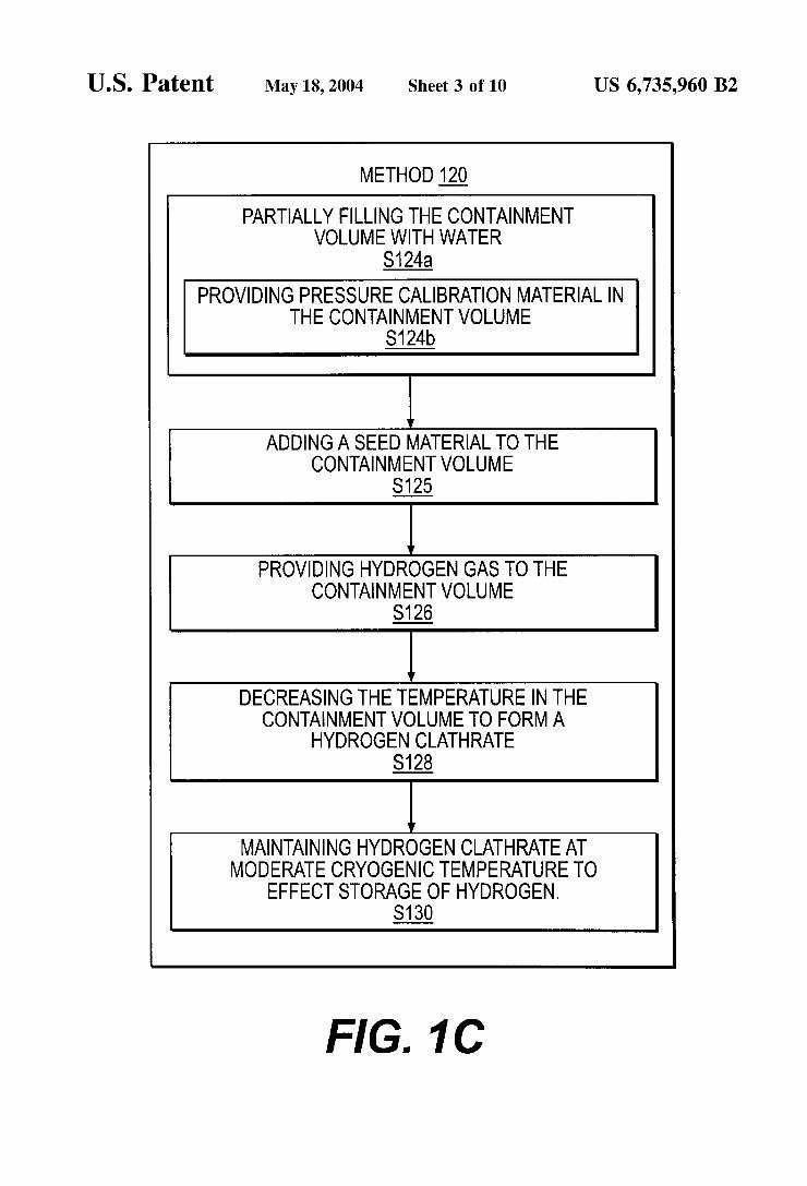
FIG. 1C is a high-level flow diagram of a method accord- 35 the diamond anvils. The retracting springs can assist in ing to the present invention for producing a hydrogen complete and smooth pressure reduction in withdrawing at hydrate at ambient pressure and low temperature using a least one of the diamond anvils from the metal gasket. seed material. Prior to beginning method 100, the user can pre-indent or
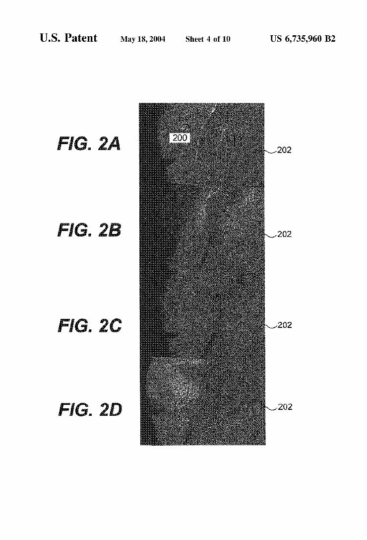
FIGS. 2A-2D are Photographs illustrating the fOrmation 4o drill the metal gasket used in the Mao-Bell cell. For of a hydrogen hydrate in accordance with exemplary example, a 0.25 mm thick metal gasket is drilled to have a embodiments of the present invention. center-hole of about 0.25 to 0.4 mm in diameter.
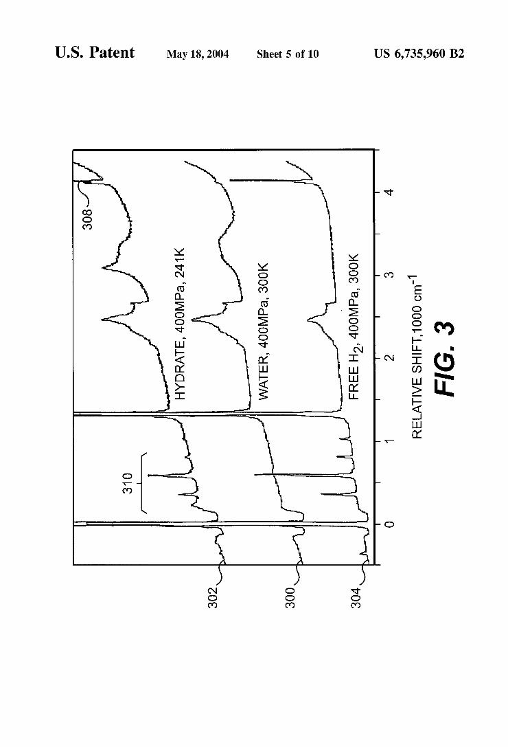
FIG. 3 is a set of comparative exemplary Raman spectra Subsequently, this drilled 0.25 mm thick metal gasket can be taken after formation of a hydrogen hydrate in accordance used between a pair of 0.7 mm diameter culets on the with the present invention. 45 respective diamond anvils used in the Mao-Bell cell. These
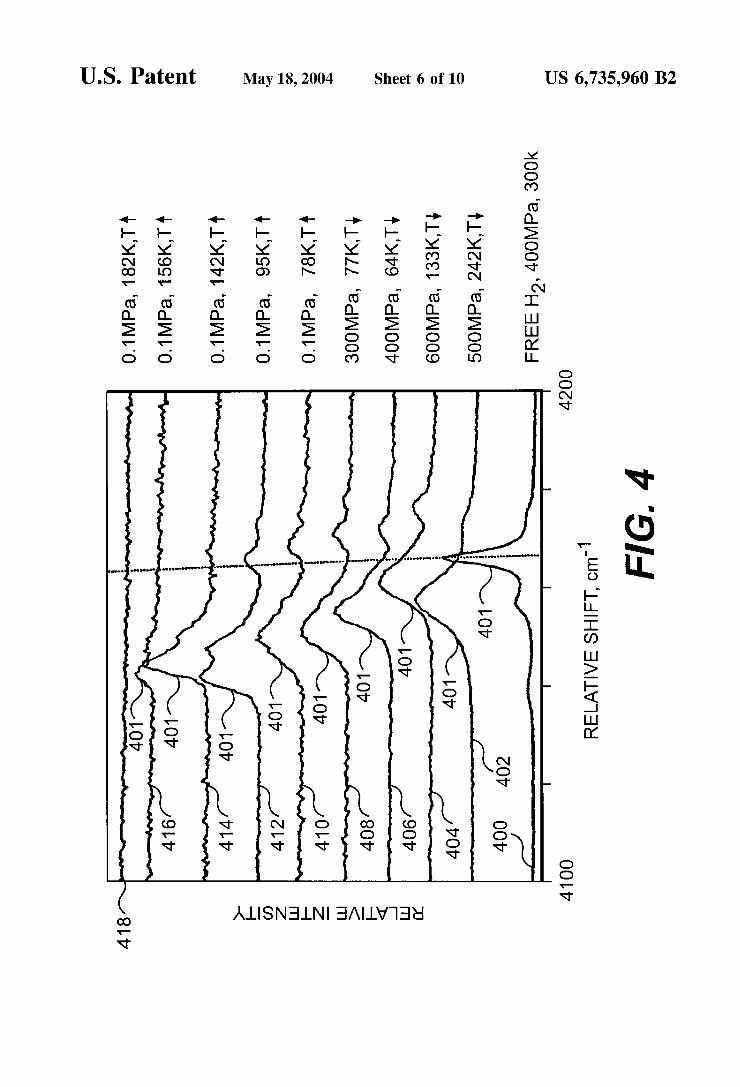
FIG. 4 is a set of enlarged detail views of exemplary dimensions can be scaled appropriately, depending on the Raman spectra of a hydrogen hydrate according to the volume of the hydrogen hydrate that is to be produced. The present invention. metal gasket does not necessarily have to be pre-indented or
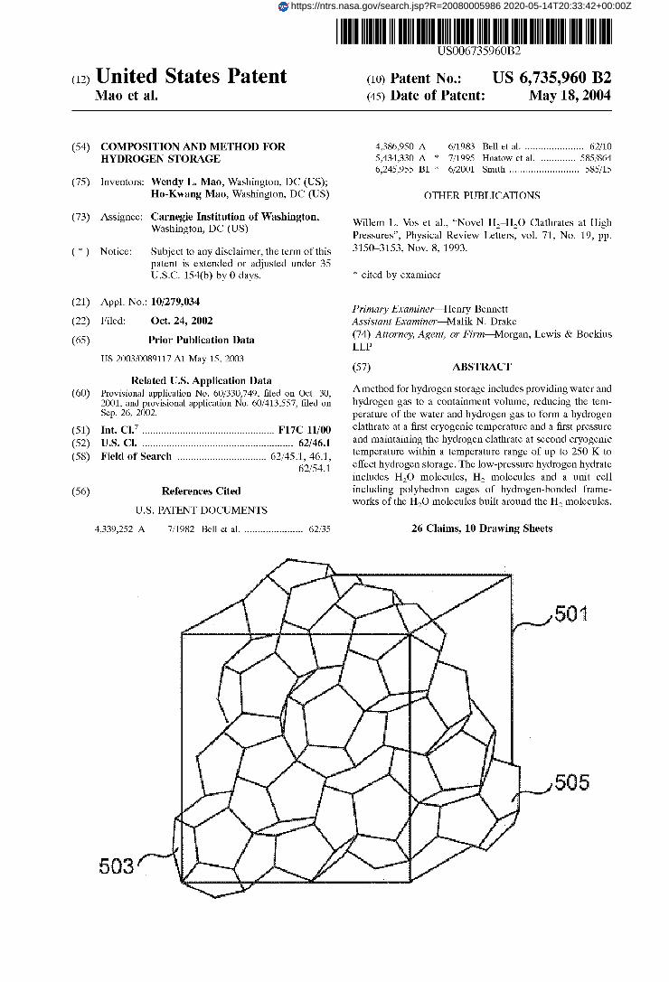
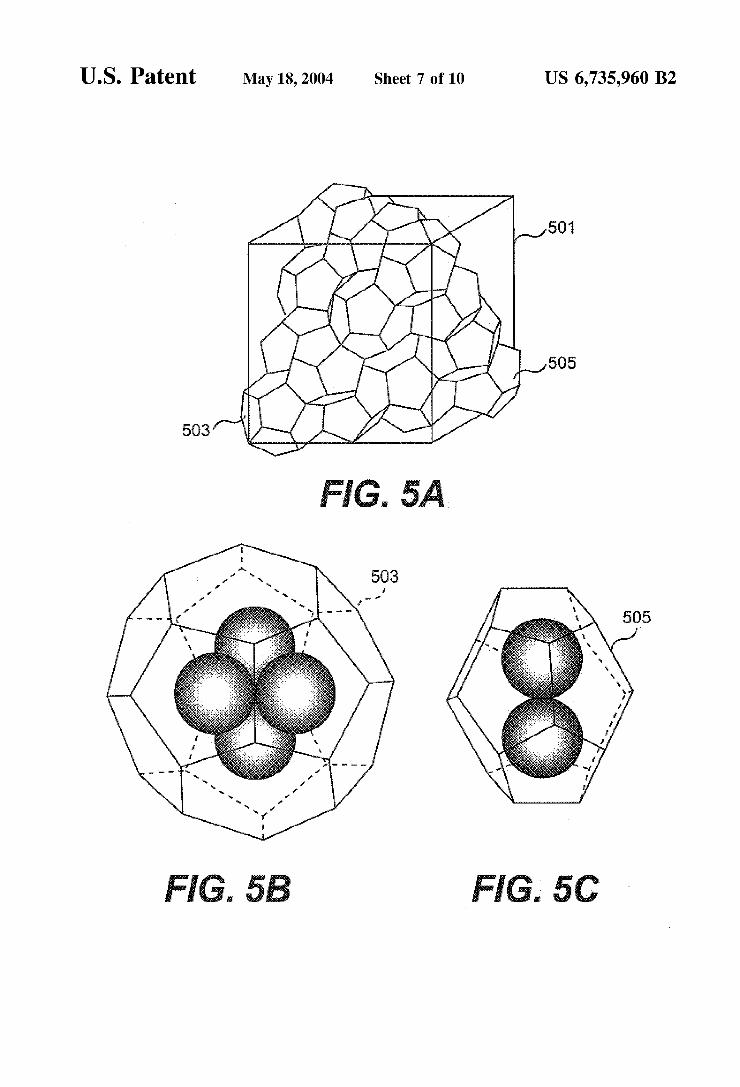
FIG. 5A is the sII crystal clathrate structure having of drilled. For example, the metal gasket can be Preformed Or 51264 cages and 5" cages. manufactured specifically for the task of forming a hydrogen
FIG, 513 is a tetrahedral cluster of four hydrogen mol- hydrate of a given size. Metals, such as T301 stainless steel ecules in the 51264 cage. and BeCu, are particularly suitable in metal gaskets for use
FIG, 5c is a cluster of two hydrogen mo~ecu~es oriented in the methods according to the present invention, although toward opposite pentagonal faces in the 51264 cage. other similar metals may be used in the gasket.
FIG. 6 depicts full-range Raman spectra showing the 55 As referred to in step S104a of FIG. 1A, a containment hydrogen molecular rotons So@), s0(1), and ~ ~ ( 2 ) at -355 volume is partially filled with water. For example, a standard cm-l, 390 cm-l, and 815 cm-l. gas tank can be filled with an amount of water in a range of
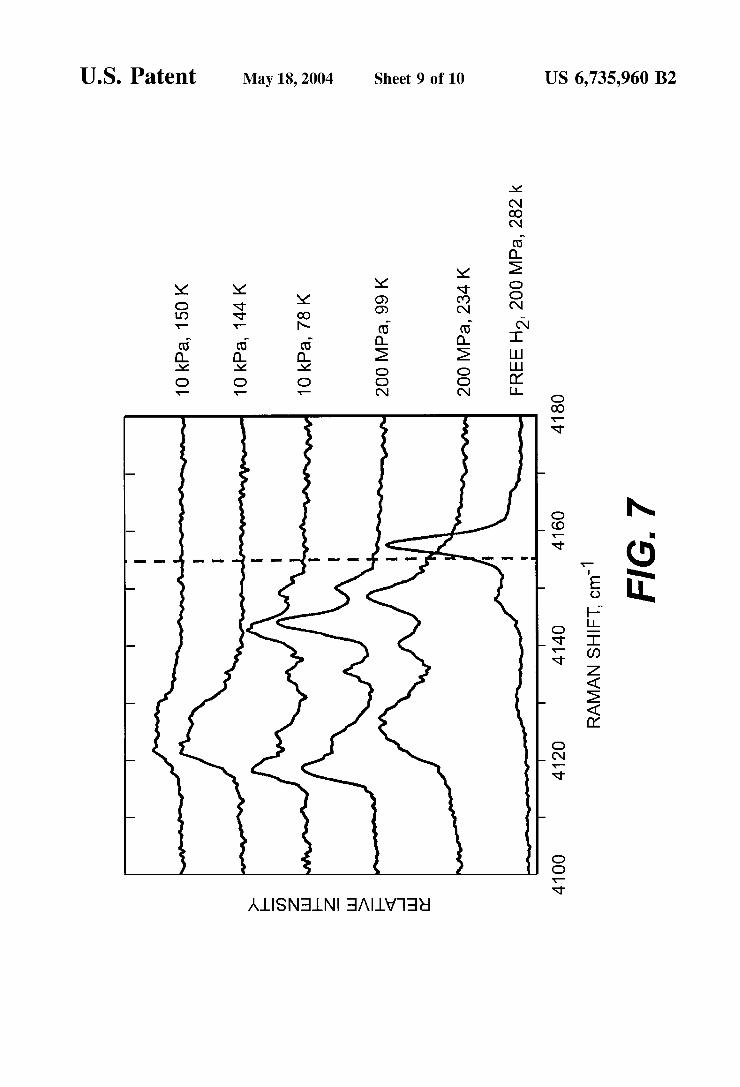
FIG. 7 depicts Raman spectra of the hydrogen hydrate 2@70% Of the Of the gas tank. The water can be according to the present invention in the region of the distilled water, de-ionized (DI) water, or any other type of
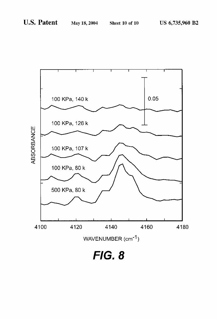
60 relatively pure water that does not have impurities which can molecular hydrogen vibrons. negatively affect subsequent processing or prevent forma- FIG. 8 depicts infrared spectra of the molecular hydrogen
in a hydrogen hydrate according to the present invention. Alternatively, as referred to in step S104b of FIG. l A , the
DETAILED DESCRIPTION OF THE step of partially filling the containment volume with water PREFERRED EMBODIMENTS 65 can include providing a pressure calibration material, such
In a hydrogen storage method according to the present as ruby grains, to the containment volume in addition to the invention, a hydrogen hydrate, such as a hydrogen clathrate, water. The pressure calibration material does not react with
and Other Objects Of the invention be apparent from the hereby incorporated by reference herein in their entireties, In
FIG. 1B illustrates a Process for forming a hydrogen
Of a hydrate'

US 6,735,960 B2 5 6
either the water or a hydrogen gas, which is subsequently In addition or in the alternative, the hydrogen hydrate can introduced into the containment volume. The inclusion of a be quenched isothermally to a moderate pressure or ambient pressure calibration material allows independent verification pressure, as referred to in SllOc of FIG. 1A. For example, of the pressure in the containment volume by external pressures from about 35 MPa to an ambient pressure of instrumental methods, such as fluorescence spectroscopy 5 about 0.01 MPa are moderate pressures. Although method through a window of a diamond anvil. The pressure Cali- 100 lists isobarically quenching the hydrogen hydrate to a bration material can also be used in more conventional moderate cryogenic temperature and then isothermally compression apparatus, such as a gas tank, if a window quenching the hydrogen hydrate to a moderate pressure, the exists such that spectroscopy or other analytical methods can hydrogen hydrate can first be isothermally quenched to a
moderate pressure and then isobarically quenched to a be performed. As referred to in step S106 of FIG. l A , a hydrogen gas is moderate cryogenic temperature.
provided to the containment volume in addition to the water. As referred to in step S112 of FIG. l A , the hydrogen If a Mao-Bell cell is used for the containment volume, the hydrate is maintained at the moderate cryogenic temperature Mao-Bell cell is positioned in a pressure vessel prior to and/or moderate to ambient pressure for as long as desired filling the containment volume within the Mao-Bell cell. In to effect storage of hydrogen. Because the hydrogen hydrate, both the case of the Mao-Bell cell and the standard gas tank, such as a hydrogen clathrate, is stable at moderate cryogenic the hydrogen gas is provided into the remaining volume of temperature and ambient pressure, the hydrogen hydrate can the containment volume at a pressure, for example, of 200 be utilized as a source of fuel, for example, in an automotive MPa. Although the method 100 is described with the water fuel cell. The stored hydrogen gas is released by warming being added first to the containment volume, an alternative the hydrogen hydrate to a temperature higher than about 140 is that the water can be added after the hydrogen gas is 20 K at which temperature the hydrogen hydrate will decom- provided. However, if the water is provided after the hydro- pose and release hydrogen. Alternatively, a controlled gen gas is provided to the containment volume, the water release can be effected by a process of gradual warming will have to be provided to the containment volume under a between 100 and 150 K that causes hydrogen gas to be higher pressure than the pressure under which the hydrogen released at a constant rate. For example, FIG. 1B illustrates gas was provided. 25 the hydrogen storage process, which uses an sII clathrate, in
After water and hydrogen gas are provided to the con- relation to an ice diagram. Of course, the hydrogen can be tainment volume, the pressure in the containment volume is stored UP to higher temperatures at higher Pressures. For increased and the temperature of the containment volume is example, a hydrogen hydrate in accordance with the Present decreased, as referred to in step SI08 of FIG. 1A to form a invention can store hydrogen UP to 25 K at a Pressure of 35 hydrogen hydrate such as a hydrogen clathrate in which 30 MPa. cages formed by the water molecules contain the hydrogen. As was noted above, method 100 may be Performed in In the case of a gas tank, the pressure can be increased by any ComPression apparatus that can compress gas and h - pumping an increased amount of hydrogen into the gas tank. uids to a Pressure of UP to 200 MPa. For example, the In the case of a Mao-Bell cell, the upper and lower anvils hydrogen hydrate can be formed in a standard metal tank, a together with the metal gasket are used to compress the 35 standard Pressure vessel Or any other type of tank that can be containment volume within the cell. In both cases, liquid used for gas storage, with ComPression Performed by either nitrogen can be used for cooling by either immersion into a gas Or liquid ComPressor. For example, suitable COmPres- liquid nitrogen or heat exchangers using a flow of liquid sion apparatus includes compressors such as the Remote nitrogen. As the pressure on the hydrogen gas and water Diaphragm ComPressor Head, a ComPressor capable of increases and the temperature decreases, the hydrogen clath- 40 Producing Pressures of 200 MPa 6% 30,006 Psi), which is rate is formed. Aclathrate, also known as a clathrate hydrate, sold by Newport Scientific, Inc. of Jessup, Md. and Pressure is a class of solids in which the guest molecules occupy, fully vessels like those sold by High Pressure Equipment Cbm- or partially, cages in the host structure made of hydrogen PanY of Erie, Pa. bonded water molecules. Examples of clathrates include the Method 100, as described above, involves the formation archetypal SI, sII, or sH clathrate crystal structures. 45 of a hydrogen hydrate at a relatively high pressure and low Typically, a clathrate includes at least two different cage temperature. However, it is possible to form and stabilize a structures. Depending on the pressure and temperature con- hydrogen hydrate at low temperatures, without the use of ditions during the formation process, some residual water high pressures, as shown in the method 120 in FIG. IC. As and/or hydrogen may be residual in the containment volume. referred to in step S124a of FIG. IC, a containment volume After the hydrogen hydrate has formed, instmmental tech- 50 is partially filled with water. Alternatively, as referred to in niques such as Raman spectroscopy, x-ray diffraction, and step S124b of FIG. IC, the step of partially filling the fluorescence spectroscopy may be used to verify the phases containment volume with water can include providing a present if the containment volume contains an appropriate pressure calibration material, such as ruby grains, to the window. The pressure and temperature can be held at containment volume in addition to the water. designated values, such as 10Ck600 MPa and 77 K, for a 5s Initially, the method 120 is similar to method 100. period of several hours to allow the hydrogen hydrate to However, method 120 is different in that seed material is stabilize, for example, as a hydrogen clathrate. added to the containment volume, as referred to in step S125
After any desired ‘‘hold” period is complete, the hydrogen of FIG. IC. In the alternative, the seed material can be added hydrate is quenched, as referred to in SllOa of FIG. 1A. For to the containment volume after the step of providing example, in the case where the hydrogen hydrate is a 60 hydrogen gas to the containment volume, as referred to in hydrogen clathrate, the hydrogen clathrate can be quenched step SI26 of FIG. IC, is performed. For example, a small isobarically to a moderate cryogenic temperature in the amount less than 5% by volume of a “seed” material could range of 77 K-250 K, as referred to in SllOb of FIG. 1A. be added to the hydrogen mix such that the hydrogen hydrate The term ‘‘moderate cryogenic temperature” is meant to will form at low temperature in a temperature range of 77 encompass any cryogenic temperature above 77 K that can 65 K-250 K and near-ambient pressure, such as 10-100 kPa. be maintained by the application of liquid nitrogen or other Seed materials can include any water-based clathrates, types of refrigerant liquids. such as a methane hydrate, ethane hydrate or a previously
10
US 6,735,960 B2 7
formed hydrogen hydrate that has a clathrate structure. The structure of the seed material should be substantially similar to a clathrate structure such that a clathrate will form when the temperature of the hydrogen mix is reduced. The seed material not only facilitates the formation of a hydrogen hydrate, such as a hydrogen clathrate, but also aids in stabilizing the hydrogen hydrate at moderate cryogenic temperatures.
After the seed material and hydrogen gas are provided, the temperature of the containment volume is decreased to form a hydrogen clathrate, as referred to in step S128 of FIG. 1C. The hydrogen clathrate is maintained at the moderate cryo- genic temperature and/or moderate to ambient pressure for as long as desired to effect storage of hydrogen, as referred to in step S130 of FIG. 1C. Because the hydrogen clathrate is formed and stabilized with the seed material, the hydrogen clathrate can be utilized as a source of fuel, for example, in an automotive fuel cell at ambient pressure and a moderate cryogenic temperature.
The method for storing hydrogen according to the present invention will be further described with reference to the following examples.
EXAMPLE I
A hydrogen clathrate was formed in a Mao-Bell cell. Portions of the discussion below refer to FIGS. 2A-2D, which are views through the window of a Mao-Bell cell illustrating the formation of the hydrogen clathrate. The field of view illustrated in FIGS. 2A-2D is approximately 0.4 mm in diameter.
AT301 stainless steel gasket having a thickness of 0.174 mm was prepared by drilling a 0.250 mm hole on center. The T301 stainless steel gasket was installed in the Mao-Bell cell in between the diamond anvils, and the resulting cell was 30% filled with distilled water. Several ruby grains were added for pressure calibration purposes. After adding the water and rubies to the cell, the cell was placed in a gas pressure vessel for filling the remainder of the cell with hydrogen gas at a pressure of 200 MPa.
The Mao-Bell cell was then pressurized to a pressure of 300 MPa and cooled isobarically from approximately ambi- ent temperature to 77 K. As shown in FIG. 2A, the pres- surized sample initially contained two portions: a liquid water portion 200 and a hydrogen gas portion 202. As shown in FIG. 2B, the water portion 200 first darkened as a result of beginning nucleation into a new phase at 249 K as a hydrogen clathrate within the water 200. Then, as the hydrogen clathrate 204 took over the water portion 200, the water portion 200 cleared, as shown in FIG. 2C. As shown in FIG. 2D, the volume of the portion increased 40%, which indicates the formation of hydrogen clathrate 204 that incor- porated hydrogen into the water. Ruby grains trapped in the hydrogen hydrate showed broadened fluorescence peaks, confirming a solid-phase clathrate. Note that the hydrogen gas portion 202, as shown in FIG. 2D, became smaller.
The presence of hydrogen clathrate was confirmed with a series of Raman spectra. FIG. 3 is a set of comparative exemplary Raman spectra taken after formation of the hydrogen clathrate. As is shown in water spectrum 300, the broad Raman peak of the liquid water at 3000-3600 cm-', indicated at 306, is sharpened in the hydrate spectrum 302 and shows four distinct peaks relative to those in the hydrogen gas spectrum 304. Intense hydrogen vibrons 308 and rotons 310 appeared in the Raman spectra of the hydrate 302. The hydrogen:water molar ratio in the hydrogen clath- rate was estimated to be about 1:2 from the intensities of the
8 hydrogen Raman peaks relative to those in the hydrogen bubble, which were consistent with a visual observation of 40% volume expansion of the hydrogen clathrate. In other words, approximately 50 giL of hydrogen can be stored and
s then later recovered from the hydrogen clathrate. The strong peak at approximately 1332 cm-I in all three spectra 300, 302, 304 is caused by the diamond anvils of the Mao-Bell cell.
The hydrogen clathrate was stabilized at a temperature of 10 77 K and 300 MPa. After the hydrogen clathrate was
stabilized, the pressure was released until atmospheric pres- sure of about 0.1 MPa was reached. A Raman spectra taken during the reduction in pressure indicated that the hydrogen vibrons and rotons in the hydrate portion remained, indicat-
15 ing successful storage of hydrogen. The hydrogen clathrate disintegrates and releases hydrogen at a temperature of 140 K and ambient pressure.
FIG. 4 is a set of enlarged detail views of exemplary Raman spectra of a hydrogen clathrate in accordance with
2o the present invention and a comparative Raman spectrum of hydrogen gas, illustrating the stability of the hydrogen clathrate at various temperatures and pressures. In particular, FIG. 4 illustrates a portion of the hydrogen clathrate between 4000 and 4100 cm-', showing the Q,(l) molecular hydrogen
25 vibron 401 in the spectrum of the hydrogen clathrate over a range of temperatures and pressures. Spectrum 400 illus- trates the Q,(l) vibron 401 of hydrogen gas at 400 MPa and 300 K. Spectra 402-418 illustrate that same Q,(l) vibron 401 in the spectrum of the hydrogen clathrate at particular
30 pressures and temperatures. Spectra 414 and 416 demon- strate that the hydrogen clathrate begins to decompose at about 140 K and is almost entirely decomposed at a tem- perature of 156 K. In general, the successive leftward shift of the Q,(l) vibron in spectra 402418 demonstrates the
35 stability of the hydrogen hydrate at ambient pressure and moderate cryogenic temperatures. More specifically, the Q,(l) vibron 401 of this hydrogen clathrate shifts to lower energy, as the temperature increases at ambient pressure.
40 EXAMPLE 2 Hydrogen clathrate was prepared in accordance with the
procedure of Example 2, except that the Mao-Bell cell was 50% filled with distilled water and 50% with the hydrogen gas. The volumes of water and hydrogen gas remaining after
45 hydrogen clathrate formation confirm the hydrogen:water molar ratio of about 1:2 within the hydrogen clathrate.
EXAMPLE 3 A hydrogen clathrate is prepared in a gas tank manufac-
50 tured by the High Pressure Equipment Company of Erie, Pa. as a Series R pressure vessel and compression is performed by a Remote Diaphragm Compressor Head from Newport Scientific, Inc. of Jessup, Md. The pressure vessel is 70% filled with water before hydrogen gas is compressed into the
55 pressure vessel to reach a pressure of 200 MPa. The pressure vessel is cooled isobarically from near ambient temperature to 200 K and then held for sufficient time to allow a hydrogen clathrate to form. The hydrogen clathrate is further cooled to 77 K and then the pressure is released isothermally
60 to ambient pressure. The hydrogen clathrate is retrieved from the pressure vessel while maintained at 77 K, and hydrogen gas is subsequently released from the hydrogen clathrate by warming to 140 K.
EXAMPLE 4 Apressure vessel, such as in Example 3, is 30% filled with
distilled water and hydrogen gas at ambient temperature and
65
US 6,735,960 B2 9 10
pressure. A 3% by volume methane hydrate is added to promote nucleation of the hydrogen clathrate. The vessel is immersed in a cryostat and cooled to 77 K. The pressure vessel is maintained at 77 K until the hydrogen clathrate is formed. The hydrogen clathrate is retrieved from the pres- s sure vessel while maintained at 77 K, and hydrogen gas is
ing from about 110 K to 140 K.
bonded frameworks of H,O molecules are built around guest 10 2 2 0 6.0252 6.0272 -0.0020 6.0472 6.0399 0.0072 molecules to form solid clathrate hydrates, thus trapping the ; ; i:;;:: i:;:;: 1::::;; i:;::: i:;:;: :::::; guest molecules at temperatures and pressures at which the 4 0 0 4.2604 4,2619 -0,0015 4,2699 4,2709 -0,0010 guest molecules would otherwise exist as free gases. Clas- 3 3 1 3.9068 3.9110 -0.0042 3.9165 3.9192 -0.0027 sical clathrates crystallize in three basic forms or cell units 3.4763 3.4798 -0.0035 3.4861 3.4872 -O.Oo10 designated as SI, sII, and sH that have about one cage, either 15 i i i:::;: i::;!: 1::::i: i::;;; i::;:: -::::i: large or small, for every six water molecules. With each cage 5 3 1 2,8771 2,8816 -0,004s 2,8844 2,8876 -0,0033
ent pressure were thought to be limited to guest/H,O molar 5 3 3 2.5927 2.5997 - ~ ~ 0 7 0 2.6043 2.6052 - ~ ~ 0 0 9 ratio of R-%, which is also known as Villard’s Rule.
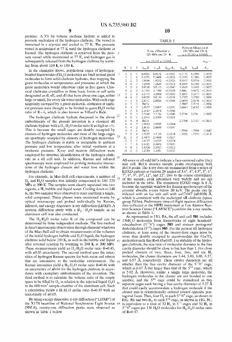
TABLE 1
Neutron diffraction at 180 MPa and 220 K a = 17.083 r 0.018A
X-ray diffraction at 220 MPa and 234 K
subsequently released from the hydrogen clathrate by warm- a = 17.047 r 0.0lOL de, -
h k 1 de& ddJ. dex,-dc,l de$ ddJ. d d In the examples above, polyhedron cages of hydrogen-
singularly occupied by a guest molecule, clathrates at ambi- 6 2 0 Be& 2.7007 2.7011 -0.0004
5 5 1 2.3913 2.3871 0.0042 5 5 3 2.2146 2.2194 -0.0048 2.2236 2.2241 -0.0005
embodiments of the present invention is a classical sII 6 4 4 Be& 2.0704 2.0717 -0.0013
This is because the small cages are doubly occupied by 9 3 1 B ~ Q , 1.7956 1.7908 0.0047
The hydrogen clathrate hydrate discussed in the above 2o 8 o o 2.1340 2.1309 0.0031
clathrate hydrate with a H,/H,O molar ratio R as high as -%. ; i::::; i:::;; :::::: clusters of hydrogen molecules and most of the large cages 7 5 5 1.7137 1.7133 0.0004 1.7152 1.7170 -0.0018 are quadruply occupied by clusters of hydrogen molecules. 25 11 3 3 1.4479 1.4460 0.0019
The hydrogen clathrate is stable or metastable to ambient i:::;; i:::;i :::::; pressure and low temperature after initial synthesis at a 6 1,3324 1,3312 o,oo12 moderate pressure. X-ray and neutron diffraction were 14 2 o 1.2054 1.2054 O.OOOO employed for structure identification of the hydrogen clath- rate as a SII cell unit. In addition, Raman and infrared 30 All-even or all-odd hkl’s indicate a face-centered cubic (fee) sPectroscoPY were employed for Probing molecular interac- unit cell. BeCu denotes sample peaks overlapping with tions of the hydrogen clusters and water host within the Be& peaks. The x-ray data are summarized from a series of hydrogen clathrate. EDXD patterns at various 28 angles of 3.6”, 4”, 4.5”, 5”, 6”,
For example, in Mao-Bell cell experiments, a mixture of 35 7’2 8’2 9’2 loo, 1 1 ’ 3 and 12”. Due to the coarse crystallinity and are ngt H, and H,O samples was initially compressed to 18&220
regions, a Hz and liquid water. down to 240
Of the peak intensities vary included in the table. The maximum EDXD range is 8 A, MPa at 300 K. The separated into two because the sapphire window for Raman spectroscopy of the
K, the two samples were observed to react and form a single, indexed with an fcc unit cell with a=17.047 (20.010) A, solid compound. These phases were monitored in-situ by 4o which is consistent with the archetypal sII clathrate (space optical microscopy and probed individually by Raman, group Fd3m). Preliminary time-of-flight neutron diffraction infrared, and energy dispersive x-ray diffraction (EDXD). A data collected at the HIPD instrument at LOS Alamos Neu- neutron diffraction study with a D,-D,O sample in an tron Science Center (“LANSCE’) confirm the x-ray results,
as shown in Table 1. aluminum cell was also conducted. As represented in FIG. 5A, the sII unit cell 501 includes
The H2:H20 ratio Of the can be 45 136H,O molecules form frameworks of eight hexakaid- determined by three independent methods. The first method odecahedron (51264) cages 503 and sixteen pentagonal is direct microscopic observation through diamond windows dodecahedron (512) cages 505, F~~ the present s~~ hydrogen of the Mao-Bell cell to obtain measurements of the volumes clathrate, at least of the twenty-four cages must be of the initial hydrogen bubble and liquid, the hydrogen more than doubly occupied to accommodate the 61+7H, clathrate solid below 240 K, as well as the bubble and liquid 50 molecules such that R=0.45+0.05. For stability ofthe hydro- after reversal reaction by warming to 280 K at 200 MPa. gen clathrate, the size ratio of molecular diameter to the free These measurements yield an H,:H,O molar ratio R=0.45, cavity diameter should be close to but less than 1. For close with 20.05 uncertainty. The second method uses the inten- packed clusters of two, three, four, five, and six H, sities of hydrogen Raman spectra for both roton and vibron molecules,othe cluster diameters are 5.44, 5.86, 6.05, 6.57, that are insensitive to the molecular environment. The 55 and 6.57 A, respectively. These cluster diameters are all R~~~~ intensities yield a H,:H,O molar ratio ~ 4 4 8 with smaller than tbe free cavity diameter of the 51264 cage, an uncertainty of 20.04 for the hydrogen clathrate in accor- which isS.67 A but larger than that of the 5” cage, which dance with exemplary embodiments of the invention. The is 5.02 A. However, the
were cryostat absorbs x-rays below 20 keV. The peaks can be
a sing1e large third method is to calculate the volume ratio of the empty hydrogen molecules in the ‘luster are not bonded to One
space to be filled by D, in relation to the injected liquid D,O be ‘Onsidered as twP 6o separate cages each having a free cavity diameter of 3.27 A in the 600 mm3 sample chamber of the aluminum cell. Such that could easily accommodate a hydrogen molecule if the
tagonal faces. Thus, four H, to each 51264 cage, as shown in uncertainty of 20.05. BY using energy dispersive x-ray diffraction (“EDXD”) at FIG. 5B and two H, to each 5” cage, as shown in FIG. 5C,
the X17B beamline of National Synchrotron Light Source 65 is equivalent to a total of 32 H, in 5” cages and 32 H, in (NSLS), twenty-one diffraction peaks were observed as 51264 cages per 136 H,O molecules for H,:H,O molar ratio shown in Table 1 below.
and the 512 cage
a calculation yields a HZ:HZo ratio R=0.45 with an cluster axis is orientationally ordered toward opposite pen-
of R=0.47.
US 6,735,960 B2 11
Raman spectroscopy was used for characterization of the bonding changes. At the formation of the hydrogen clathrate, broad liquid water OH peaks at 300Ck3600 cm-' transform to sharp peaks typical of sII clathrates. Meanwhile, hydro- gen roton peaks appear at 300450 cm-', and vibron peaks at 4100-4200 cm-', as shown in FIG. 6. Hydrogen rotons, S,(O), So(l), and S,(2), in the clathrate are similar in frequency to those of pure hydrogen, indicating that the hydrogen molecules in clathrate cages are still in free rotational states. H-H vibrons of the new clathrate, on the other hand, are distinct from vibrons of other known phases in the H,-H,O system. Vibrons of the sII hydrogen clathrate, in contrast, appear at 4120-4150 cm-', as shown in FIG. 7, which is significantly below the dominant Q,(l) vibron at zero pressure, which is 4155 cm-'. Once the sII hydrogen clathrate is synthesized, it shows remarkable sta- bility or metastability. For example, the sII hydrogen clath- rate persisted at 200 MPa to 280 K. Along another Pressure- Temperature path, a hydrogen clathrate remained after the sII hydrogen clathrate was cooled down to 78 K at 200 MPa and then exposed to a vacuum of approximately 10 kPa in a cryostat. Other Pressure-Temperature paths can be used for other types of hydrates or clathrates.
High-resolution vibron spectra, as shown in FIG. 7, for the hydrogen clathrate display two groups of multiplets of nearly equal intensities that supports the assignment of two equal populations of hydrogen molecules in eight 51264 and sixteen 5" cages. The lower-frequency group at 41154135 cm-' is assigned to the loosely fitted tetrahedral molecular cluster in the 51264 cage and the higher-frequency group at 4135-4155 cm-' is assigned to two molecules ordered in the 5" cage. Warming up from 78 K at 10 kPa, the higher- frequency vibrons gradually vanish above 115 K, while the lower-frequency vibrons and the sII crystal structure persist to 145 K, which is consistent with the above peak assign- ment as the sII structure is known to remain stable with filled 51264 cages and empty 5" cages, such as SF6.17H,0.Above 145 K at 10 kPa, the lower-frequency vibrons gradually disappear and the crystal structure collapses.
Infrared spectra of the hydrogen clathrate also show a hydrogen vibron peak at 4145 cm-' and a very weak peak at 4125 cm-', as shown in FIG. 8. Unlike the Raman vibron intensity which is intrinsic to the hydrogen molecule, the infrared vibron intensity is highly sensitive to the environ- ment. Being a homonuclear molecule, a free hydrogen molecule does not have an electric dipole and thus does not absorb infrared. Bonded in a solid, the hydrogen electron density is distorted and shows collision induced infrared absorption. The relatively high intensity of the 4145 cm-' peak is consistent with a bimolecular cluster ordered in the 5" cages, and the lack of intensity of the 4125 cm-' peak is consistent with a fluid-like cluster in the loosely-fitted 51264 cages. Upon changing pressure-temperature conditions the infrared vibrons follow similar behavior as the Raman vibrons of the hydrogen clathrate.
While the invention has been described by way of exem- plary embodiments, it is understood that the words which have been used herein are words of description, rather than words of limitation. It will be apparent to those skilled in the art that various modifications and variations can be made in the composition and method for hydrogen storage of the present invention without departing from the spirit or scope of the invention. Thus, it is intended that the present inven- tion cover the modifications and variations of this invention provided they come within the scope of the appended claims and their equivalents.
12 What is claimed is: 1. A method for hydrogen storage, comprising: providing water and hydrogen gas to a containment
volume; reducing the temperature of the water and hydrogen gas to
form a hydrogen clathrate at a first cryogenic tempera- ture and a first pressure; and
maintaining the hydrogen clathrate at second cryogenic temperature within a temperature range of up to 250 K to effect hydrogen storage.
2. The method for hydrogen storage of claim 1, further
isobarically quenching the hydrogen clathrate from the first cryogenic temperature to the second cryogenic temperature.
3. The method for hydrogen storage of claim 1, further
isothermally quenching the hydrogen clathrate from the first pressure to a quenched pressure within a quench pressure range of 35 MPa to 10 kPa.
4. The method for hydrogen storage of claim 1, wherein the first pressure is between 10Ck600 MPa and the first cryogenic temperature is between 77 K-250 K.
5 . The method for hydrogen storage of claim 1, further comprising:
adding a seed material to the containment volume. 6. The method for hydrogen storage of claim 5, wherein
the seed material is a clathrate, the first pressure is between 30 1Ck100 kPa and the first cryogenic temperature is between
7. The method for hydrogen storage of claim 6, wherein the seed material is added in an amount less than or equal to 5% by volume of the mixture of hydrogen and water.
comprising:
1~
comprising:
20
zs
77 K-250 K.
35 8. A method for hydrogen storage, comprising: providing a containment volume having a specified vol-
partially filling the containment volume with water; providing hydrogen gas to the specified volume; cooling the containment to a first cryogenic temperature
in a cryogenic temperature range of up to 250 K to form a hydrogen hydrate; and
maintaining the hydrogen hydrate within pressure range of 35 MPa to 0.01 MPa to effect hydrogen storage.
9. The method of claim 8, further comprising: pressurizing the containment volume to a first pressure
within a pressure range of 10Ck600 MPa; and quenching the first pressure on the hydrogen hydrate to a
quenched pressure within a quenched pressure range of 35 MPa to 0.01 MPa.
10. The method of claim 9, wherein pressurizing the containment volume vessel is performed in a pressure vessel
ume;
40
45
55 using a compressor. 11. The method of claim 8, further comprising: quenching the first cryogenic temperature to a quenched
temperature within a quenched temperature range of 77 K to 250 K.
60 12. The method of claim 8, further comprising: adding a seed and stabilizer material to the containment
13. The method of claim 12, wherein the seed material is a clathrate.
14. The method for hydrogen storage of claim 12, wherein the seed material is added in an amount less than or equal to 5% of the specified volume.
volume.
65
US 6,735,960 B2 13 14
15. The method for hydrogen storage of claim 8, wherein the step of partially filling the containment volume with water provides water in an amount equal to 20 to 70% of the specified volume. H,O molecules;
16. The method of claim 8, wherein the hydrogen hydrate s is a clathrate.
17. A method for hydrogen storage, comprising: providing a containment volume having a specified vol-
partially filling the containment volume with water; providing hydrogen gas to the containment volume; pressurizing the containment volume to a first pressure
cooling the containment volume to a first cryogenic 15
the H, molecules, wherein there are at least two dif- ferent cage structures.
22. A low-pressure hydrogen hydrate, comprising:
HZ molecules; and a unit cell including polyhedron cages of hydrogen-
bonded frameworks of the H,O molecules built around the H, molecules, wherein the unit cell is a SI unit cell.
ume; 23. A low-pressure hydrogen hydrate, comprising: H,O molecules; H, molecules; and a unit cell including polyhedron cages of hydrogen-
bonded frameworks of the H,O molecules built around the H, molecules, wherein the unit cell is a sH unit cell.
within a pressure range of 10Ck600 MPa;
temperature within a moderate cryogenic temperature range of 77 K to 250 K to form a hydrogen hydrate;
quenching the first pressure in the containment volume to
24. A low-pressure hydrogen hydrate, comprising: H,O molecules; H, molecules; and
a quenched pressure within a pressure range Of 35 MPa a unit cell including polyhedron cages of hydrogen- 20 bonded frameworks of the H,O molecules built around
the H, molecules, wherein the unit cell is a sII unit cell. 25. The low-pressure hydrogen hydrate according to
claim 24, wherein the sII unit cell includes 136 H,O molecules that form frameworks around eight hex&aid-
is added to the containment volume during the step of 2s odecahedron and sixteen pentagonal dodecahedron cages, partially filling the containment volume with water. wherein some of the cages are more than doubly occupied
19. The method of claim 17, wherein pressurizing the with H, molecules, containment volume vessel is performed using a compres- sor. H,O molecules;
performed using liquid nitrogen.
to 0.01 MPa; and maintaining the hydrogen hydrate within the moderate
cryogenic temperature range to effect hydrogen stor- age.
18. The method of claim 17, wherein calibration material
26. A low-pressure hydrogen hydrate, comprising:
HZ molecules; and a unit cell including polyhedron cages of hydrogen-
bonded frameworks of the H,O molecules built around the H, molecules, wherein approximately 50 g/L of H,
20. The method of claim 17, wherein said maintaining is 30
21. A low-pressure hydrogen hydrate, comprising: H,O molecules; H, molecules; and 3s molecules are stored for later recoverv. a unit cell including polyhedron cages of hydrogen-
bonded frameworks of the H,O molecules built around * * * * *