i ii !i ‘i i automated seed manipulation and … automated seed manipulation and planting group...
TRANSCRIPT
I I II ! I ‘ I I I I I I I I I I I I . I I I
AUTOMATED SEED MANIPULATION AND PLANTING
Prepared by
Ray Garcia Javier Herrera Scott Holcomb Paul Kelly Scott Myers
Manny Rosendo Herbert Sivitz Dave Wolsefer
9
PRECEDING PAGE BLANK NOT FILMED
https://ntrs.nasa.gov/search.jsp?R=19890014649 2018-07-17T06:46:28+00:00Z

I I I I I I I I I I I I I I I I I I I
SUMMARY
The Automated Seed Manipulation and Planting Group was formed to develop a system for safe seed separation, acquisition, and planting operations for the Controlled Ecological Life Support System (CELSS) project currently under development at NASA's Kennedy Space Center.
The seeding systems constructed and tested during the Spring Semester, 1988 were diverse and indicated promise for future development.
utilizing pressure gradients to move and separate wheat seeds. These separators are called @*minnow buckets@@ and use air, water, or a combination of both to generate the pressure gradient.
Electrostatic fields were employed in the seed separator constructed by the Electrical Division. This separator operates by forcing a temporary electric dipole on the wheat seeds and using charged electrodes to attract and move the seeds.
Seed delivery to the hydroponic growth tray is accomplished by the seed cassette. The cassette is compatible with all the seed separators, and it consists of a plastic tube threaded with millipore filter paper. During planting operations, the seeds are placed in an empty cassette. The loaded cassette is then placed in the growth tray and nutrient solution provided. The solution wets the filter paper and capillary action draws the nutrients up to feed the seeds.
These seeding systems were tested and showed encouraging results. support the growth of wheat plants. Problems remaining to be investigated include ilrproving the success of delivering the seeds to the cassette and providing adequate spacing between seeds for the electric separator.
The Mechanical Division fabricated three seed separators
Seeds were effectively separated and the cassette can
10

TABLE OF CONTENTS I I I I I
I I I I I I
INTRODUCTION ................................................ 13
Problem Definition ..................................... 13
Design Criteria ........................................ 14
MECHANICAL SEEDERS .......................................... 16
MINNOW BUCKET SEEDER ONE (MBS-1) ............................ 16
Seed Capture Holes ................................ 17 Concepts and Designs ................................... 16
MBS-1 Pneumatics .................................. 18 Tangential Flow ................................ 18 Main Air Flow .................................. 18 Seed Blower .................................... 19 Seed Cassette .................................. 20
Planting Operations ............................... 21
Results to Date ........................................ 22
Recommendations for Future Work ........................ 24
MINNOW BUCKET SEEDER TWO (MBS.2) ............................ 26 Concepts and Designs ................................... 26
Experiment 1 ...................................... 26
Experiment 2 ...................................... 27 Experiment 3 ...................................... 27 Experiment 4 ...................................... 29
Results to Date ........................................ 29 Recommendations for Future Development ................. 29
MINNOW BUCKET SEEDER THREE (MBS-3) .......................... 30
Concepts and Designs ................................... 30 End Effector ...................................... 31
Water/Seed Separator .............................. 32
I I I
11

Results to Date ........................................ 33
Experiment 1 ...................................... 33
Experiment 2 ...................................... 33
Experiment 3 ...................................... 34
Recommendations for Future Development ................. 35 Experiment with Water/Seed Separator .............. 35
ELECTRICAL SEEDERS .......................................... 36 Concepts and Designs ................................... 36
Electrode Shapes and Field Configurations ......... 36 Seed Separation and Implantation .................. 38 Design Improvements ............................... 39
Results to Date ........................................ 40 Inhibiting Factors ................................ 40
Recommendations for Future Development ................. 41 Final Design and Fabrication ...................... 41
APPENDIX B .................................................. 44
I I I I I
I I I I I
12
I I I I I I I I I I I I I I I I I I I
INTRODUCTION
Problem Definition
The ultimate goal of the Controlled Ecological Life Support System (CELSS) project is the construction of a self-contained bioregenerative life support module to provide nutrition for a permanent human presence in space. A critical element required in such a module will be a system to accomplish manipulation and planting of seeds that will be grown to provide food for the crew. This Seed Planting System (SPS) must operate automatically to reduce human involvement in the tedious operations to be described and to preserve probable cleanliness requirements for the growth chamber.
The first requirement for the SPS is the non-damaging separation of the seeds. The design group was instructed to consider the seeds to be stored so that they will be free to move within the container and not housed in individual storage cubicles. In this worst-case scenario, the formidable task of locating and acquiring individual seeds becomes obvious. Since the CELSS module will operate in the micro-gravity environment of space, any contact between a seed and a moving instrument will cause the seed to move away from the object to an undetermined location. As it moves, the seed may strike other seeds, eventually causing a rapid dispersion of seeds and thus making
seed location and acquisition a difficult dynamic problem. Once the seeds have been separated they must be planted.
The SPS will safely transfer the seeds from the storage container and deposit them in the pre-determined locations in the growth tray. The ability to exactly plant seeds is necessary for the SPS so the seeds will be in position to receive the proper amounts of light and nutrients. Seeds placed at random in the growth tray are not guaranteed adequate light, nutrients, and space to grow and therefore are not likely to survive.
13
The SPS must also be capable of planting seeds at a rate sufficient to sustain the humans depending on CELSS. Considerations were made for the possibility that during CELSS module operation, all crops but one become contaminated and unusable. In this situation, the crew must depend solely on the remaining crop for nutrition. Calculations were completed based on the consumption rate necessary for sustenance on a sample crop (in this case, wheat) to determine a maximum planting rate capability for the SPS (Appendix A).
state or dry, non-germinated condition has not been definitely settled upon for CELSS. Planting a pre-germinated seed has the advantage of partially ensuring the successful maturation of the seed: however, the germinated seed is a very delicate living organism and extreme care must be taken during planting operations so as not to damage either the seed coat or emerging radical. Dry seeds are much more resistant to physical damage but planting dry seeds increases the possibility that non-viable seeds will take up valuable space in the growth tray. In view of these facts, the SPS should therefore be able to successfully operate and deliver seeds in either a wet or dry condition.
The topics discussed define the ares of major concern in designing an SPS for use in the CELSS module. The ideas and experiments to be presented in this report address these problems and solutions felt to be useful in our future work.
The decision whether to plant the seeds in a wet, germinated
Desian Criteria
Following are the design criteria decided upon completed during the Fall semester, 1987:
from research
1. SPS must not rely on earth's gravity to accomplish seeding operations.
2. SPS operations should be automated to minimize human involvement.
14
I I I I I I I I I I I I I I I I I I I
I I I I I
I I I I I
3 .
4 .
5 .
6 .
7.
Seed storage containers must allow for freedom of movement of the seeds within the container. This is to demonstrate the worst case scenario for seed location and acquisition.
Contact with the seeds by instruments, container, etc. must not inflict damage which would cause the seeds to become non-viable in wet or dry planting.
The SPS must plant seeds in specific locations in the growth tray.
SPS operations must not contaminate the growth chamber environment by releasing fluids or other material.
SPS must be capable of planting seeds at a sufficient rate to support human consumption requirements.
With these design criteria in mind, the Automated Seed Manipulation and Planting Group began construction and testing of seeding system concepts developed during the Fall semester of 1987.
I I I I I I
15
MECHANICAL SEEDERS
MINNOW BUCKET ONE (MBS-1)
Concepts and Desisns
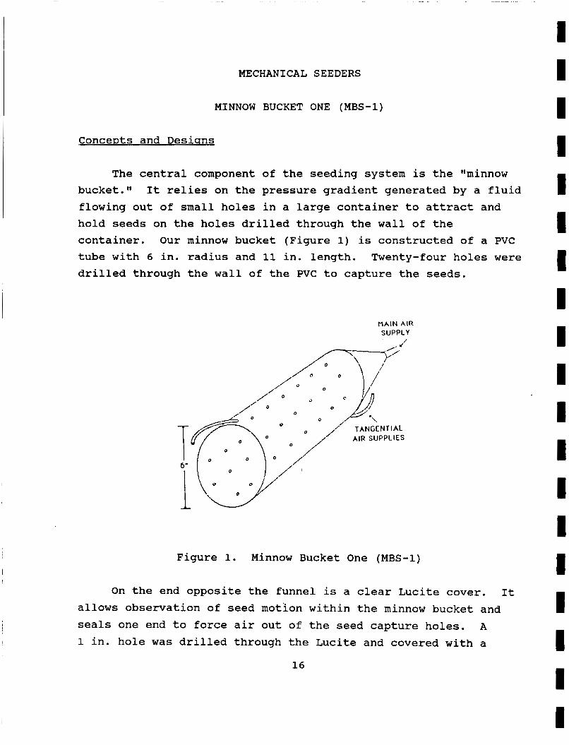
The central component of the seeding system is the llminnow bucket." flowing out of small holes in a large container to attract and hold seeds on the holes drilled through the wall of the container. Our minnow bucket (Figure 1) is constructed of a PVC tube with 6 in. radius and 11 in. length. Twenty-four holes were drilled through the wall of the PVC to capture the seeds.
It relies on the pressure gradient generated by a fluid
MAIN AIR SUPPLY ' /
3 0 @AI '. /
/' O
,/ TANGENTIAL T f i , o /' AIR SUPPLIES
Figure 1. Minnow Bucket One (MBS-1)
On the end opposite the funnel is a clear Lucite cover. It allows observation of seed motion within the minnow bucket and seals one end to force air out of the seed capture holes. A
1 in. hole was drilled through the Lucite and covered with a
16
I I I I I I I I I I I I I I I I I I I
rubber diaphragm with radial slits to act as the entrance/exit for the seed cassette.
In order to guide the cassettes and support them as they wait to accept seeds, hooks were installed. The hooks are aluminum and ensure that the cassette is directly beneath a row of seed capture holes.
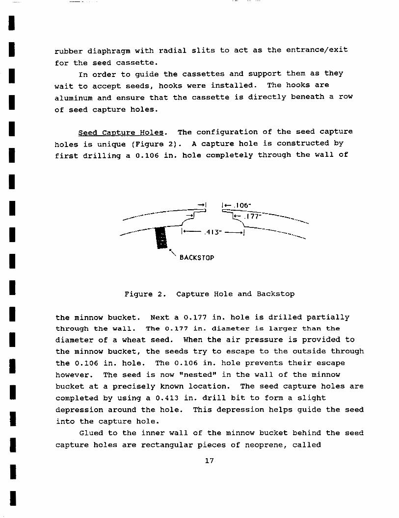
Seed CaDture Holes. The configuration of the seed capture holes is unique (Figure 2 ) . A capture hole is constructed by first drilling a 0.106 in. hole completely through the wall of
' BACKSTOP
Figure 2. Capture Hole and Backstop
the minnow bucket. Next a 0.177 in. hole is drilled partially through the wall. The 0.177 in. diameter is larger than the
diameter of a wheat seed. the minnow bucket, the seeds try to escape to the outside through the 0.106 in. hole. The 0.106 in. hole prevents their escape however. The seed is now ggnestedgw in the wall of the minnow bucket at a precisely known location. completed by using a 0.413 in. drill bit to form a slight depression around the hole. into the capture hole.
capture holes are rectangular pieces of neoprene, called
When the air pressure is provided to
The seed capture holes are
This depression helps guide the seed
Glued to the inner wall of the minnow bucket behind the seed
17
backstops. bucket, they impact against the backstops. This impact decreases the seed's velocity, allowing the air flow to divert the seed into a seed capture hole. Neoprene was chosen because its spongy character does not damage the seeds during repeated impact. The backstops were determined to be necessary due to problems in testing the seeder. Seeds were only captured by the holes on the bottom half of the minnow bucket. The tangential air flow required to force the seeds completely around the inner wall of the container gave the seeds a velocity that was too great for the seeds to be attracted to the holes by the pressure gradient. In order to show that the seed separation system is "gravity independent1@ (seeds can be captured regardless of the direction of gravity), seeds must be captured in a row of holes at the top of the minnow bucket. Testing following the installation of backstops r e s u l t e d i n seeds being captured i n a l l t h e h o l e s ,
including the top row.
As the seeds rush along the wall of the minnow
MBS-1 Pneumatics. The pneumatic system of the MBS is the most vital part of seed manipulation. After several different air flow configurations were tried the class members working on MBS 1 decided on the following air system(s).
Tangential Flow: Tangential flow hoses are located on the inside wall at the ends of the MBS. These tangential sources provide a clockwise vortex circulation on the inside wall of the seeder. This serves the primary purpose of moving the seeds to the seed capture holes. The vortex circulation moves the seeds around the wall, into the specially designed Ilbackstops" and then finally into the capture holes.
Main Air Flow: The main enters MBS 1 and diffuses through the funnel at one end. This air flow provides the majority of the pressure gradient holding the seeds to the walls. The increase in pressure provided by the main source forms a
18
I I I I I I I I I I I I I I I I I I I
I I I I I I I I I I I I I I I I I I I
significant pressure gradient that holds the seeds at the top of the MBS-1. The main source is needed in an earth atmosphere because seeds at the top of the MBS need must resist gravity to remain in position. In micro-gravity the need for the main pressure source would be reduced or possibly eliminated and the tangential source would provide a strong enough pressure gradient to hold the seeds in the holes. Micro-gravity will also allow the overall air flow pressure going into the MBS-1 to be decreased. The current testing pressure is approximately 80 psi.
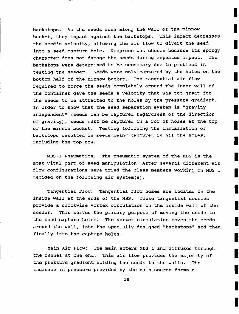
Seed Blower: Another component of the MBS 1 pneumatics is the "seed blowergt (Figure 3). The seed blower provides the positive air flow source needed to blow the seeds out of the seed capture holes and into the seed cassette. The prototype seed blower consists of a 15 in. PVC tube and six air openings. The air openings, which are spaced to line up exactly with a row capture holes, contain half inch pieces of vinyl tubing to concentrate the positive air flow into the capture holes.
Figure 3. Seed Blower
19
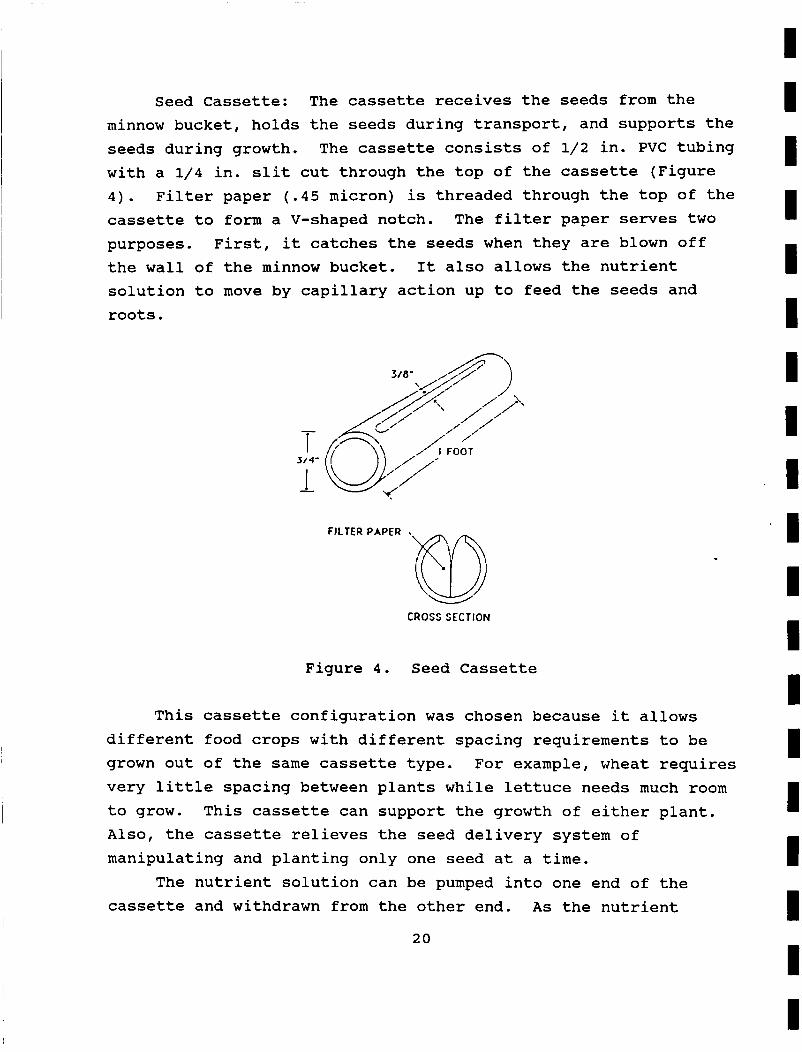
Seed Cassette: The cassette receives the seeds from the minnow bucket, holds the seeds during transport, and supports the seeds during growth. The cassette consists of 1/2 in. PVC tubing with a 1/4 in. slit cut through the top of the cassette (Figure 4). Filter paper (.45 micron) is threaded through the top of the cassette to form a V-shaped notch. The filter paper serves two purposes. the wall of the minnow bucket. It also allows the nutrient solution to move by capillary action up to feed the seeds and roots.
First, it catches the seeds when they are blown off
3/4'
CROSS SECTION
Figure 4. Seed Cassette
This cassette configuration was chosen because it allows different food crops with different spacing requirements to be grown out of the same cassette type. For example, wheat requires very little spacing between plants while lettuce needs much room to grow. This cassette can support the growth of either plant. A l s o , the cassette relieves the seed delivery system of manipulating and planting only one seed at a time.
cassette and withdrawn from the other end. A s the nutrient The nutrient solution can be pumped into one end of the
20
I I I I I I 1 I I I I I I I I I I I I
I I I I I I I I I I I I I I I I I I I
solution passes through the cassette, the filter paper becomes wet. The seeds draw nutrients from the filter paper to support their growth.
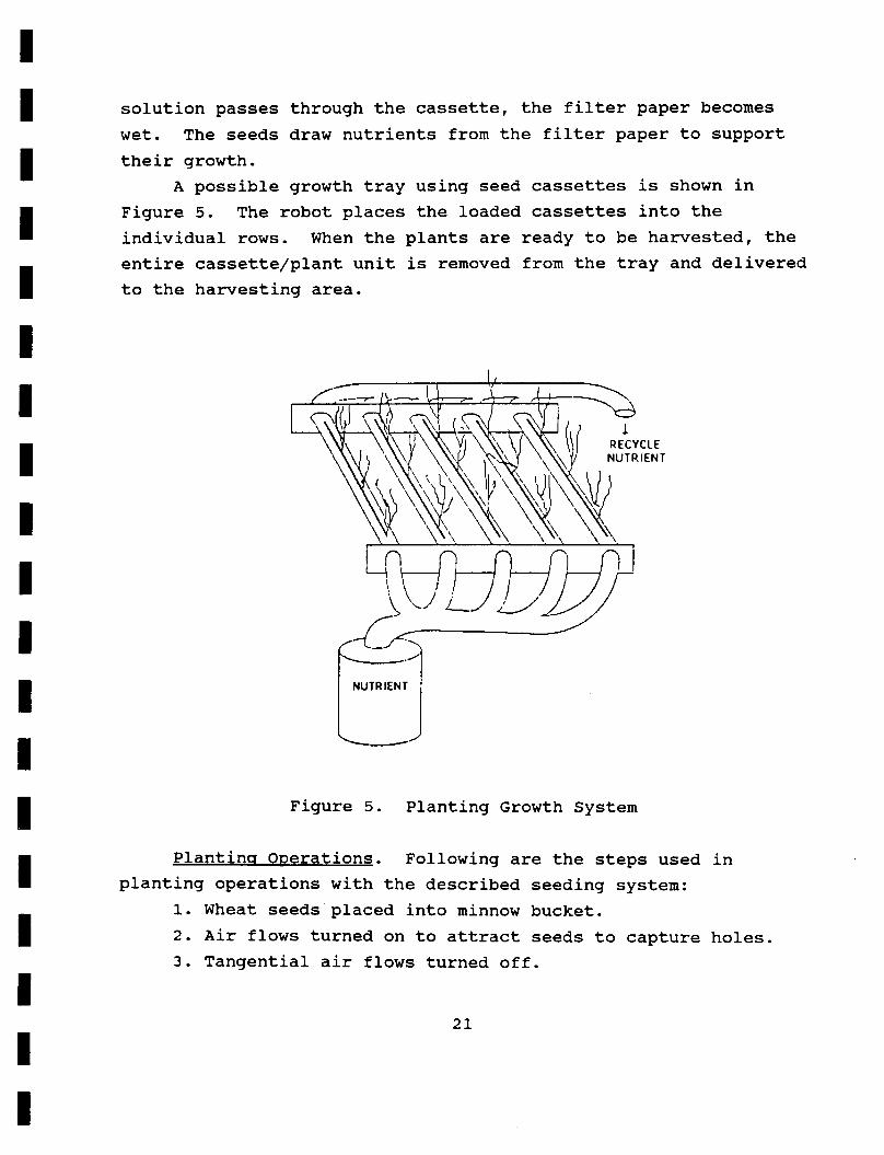
A possible growth tray using seed cassettes is shown in Figure 5. The robot places the loaded cassettes into the individual rows. When the plants are ready to be harvested, the entire cassette/plant unit is removed from the tray and delivered to the harvesting area.
NUTRIENT
Figure 5. Planting Growth System
Plantins ODerations. Following are the steps used in
1. Wheat seeds placed into minnow bucket. 2. Air flows turned on to attract seeds to capture holes. 3. Tangential air flows turned off.
planting operations with the described seeding system:
21
4 . Empty cassette inserted into minnow bucket directly under a row of capture holes.
5. Burst of positive pressure from outside the minnow bucket forces seeds out of capture holes and into cassette.
6. Loaded cassette withdrawn and placed in germination area or growth tray.
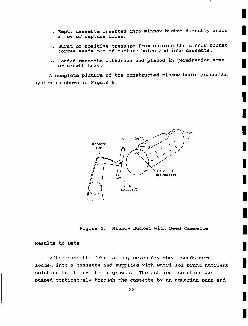
A complete picture of the constructed minnow bucket/cassette system is shown in Figure 6 .
/ / '\J- *\ CASSETTE 01 APtIR AGM
CASSETTE lM
Figure 6. Minnow Bucket with Seed Cassette
Results to Date
After cassette fabrication, seven dry wheat seeds were loaded into a cassette and supplied with Nutri-sol brand nutrient solution to observe their growth. The nutrient solution was pumped continuously through the cassette by an aquarium pump and
22
I I I I I I I I I I I I I I I I I I I
I I I I I I I I I I I I I I I I I I I
returned to the supply bucket to form a closed-loop system. The cassette was placed in the I'greenhousel' constructed in the EGM 4001 design room to obtain the necessary light.
weeks. Time limitations prevented the observation of the wheat's growth to full maturation. It remains to be determined if the volume of the seed cassette is sufficient to contain the roots of the wheat.
The seeds were observed to experience normal growth for two
Tests were conducted to measure the elapsed time from the start of the air flow to the time when seeds moved to the capture holes (Appendix A). These tests showed that 90% of the holes would capture a seed in an average time of 45.3 seconds. On the average, it took 1:08 minutes for 95% of the holes, and 1:25 minutes for 100% of the holes to acquire seeds. During the tests, however, the minnow bucket split and the funnel attachment dislodged. The epoxy used to connect the minnow bucket and end attachments was not strong enough to withstand the repeated exposure to 80 psi. To correct this, the minnow bucket was re- glued, aluminum hose clamps fabricated and installed to prevent the outward expansion of the minnow bucket, and a French press constructed to resist the tendency for the funnel and Lucite over from uncoupling. reductions in the time required to capture seeds. With the safety modifications, the average time for 90% of the holes to acquire seeds was 24.9 seconds. The time required f o r 95% of the
holes was 30 seconds, and 100% of the holes caught seeds after 44.3 seconds.
The capture tests were redone with significant
These results are encouraging since seed damage is minimized when the holes capture seeds quickly. holes, the tangential flow may be turned off and the main air supply pressure reduced. This situation is favorable since the seeds are no longer swirling around and impacting the backstops, minnow bucket wall, and cassette guide hooks.
The seed blower's accuracy at blowing the seeds off the capture holes was tested next (Appendix B). Cassettes with dry
Once the seeds are in the
23
and wet filter paper were loaded. filter paper was too stiff and elastic to accept the seeds. could be corrected by redesigning the cassette to reduce the amount of contact between the sides of the V-shaped portion of the filter paper.
Results indicated that the dry This
The wet filter paper caught an average of 5 out of 6 seeds. The water helped to lubricate the filter paper so the seeds could enter more easily. Planting dry seeds into a wet cassette could be advantageous if the planting scenario called for pre- germinated seeds. The wet cassette is an ideal area for the seeds to germinate before planting.
failed. The pressure inside the minnow bucket was too great for the rubber material to maintain its shape. The pressure forced the radial slits in the interior and exterior rubber doors to open outward. This provided a huge outward f l o w pattern t h a t
allowed seeds to exit the minnow bucket. For future development, an adequate system to allow the cassette to enter and exit the minnow bucket must be designed. It must prevent the seeds from shooting out of the bucket and still allow the cassette to be inserted.
Throughout all the tests, the rubber diaphragm repeatedly
Recommendations for Future DeVelODment
The results of this work have shown that this type of seed separation and planting system is feasible for micro-gravity operations. It would be desirable to have a vision system to "look" in the seed capture holes to determine when the seeds have been captured. The vision system could relay the data (number of holes with seeds) to the computer to determine when to turn off the tangential air flow in preparation for cassette entry.
of a cassette entry/exit door system, redesign of the cassette filter paper orientation for dry seed planting, and improving seed blower performance.
Improvements required for the current system include design
2 4
I I I I I I I I I I I I I I I I I I I
I 1 ' I I I I I I I I I I II I I I - I I I
It is anticipated that this system would operate more effectively in micro-gravity. The pressure gradient and flow velocity required to separate the seeds would reduce to nearly zero. The positive pressure delivered by the seed blower would also decrease.
The potential applications of this minnow bucket system are intriguing. One minnow bucket-cassette system could be used to separate and plant any type of seed. A minnow bucket could be constructed with rows of holes suited for specific seed types. For instance, a bucket could have holes sized and spaced for wheat, holes sized and spaced for beans, etc. During seeding operations, only the holes that serve the type of seed to be planted could be used. The other holes could be temporarily plugged to prevent seed attraction. A different crop could then be planted by removing the plugs covering its holes and following the described planting operations.
25

MINNOW BUCKET TWO (MBS-2)
Concepts and Desisns
The tube retrieval MBS design is basically a simple MBS with a bracket holding the transport tubes on the inside (Figure 7.) This bracket is approximately 1/4 inch from the inner wall of the MBS. exit the MBS. bracket are aligned. The main bracket is connected to the rotating block. and bracket remain stationary. This allows any row of the MBS's seed capture holes to position itself over the main bracket.
The space allows seeds to enter the transport tubes and The seed capture holes and the holes of the main
The MBS is permitted to rotate while the block
W
Figure 7. Minnow Bucket Two (MBS-2)
Experiment 1. The experiment consisted of placing approximately forty dry wheat seeds in the MBS. As the seeds migrated to the seed capture holes, the MBS was rotated until the main bracket was directly under a row of seeds. Air was then
26
I 1 1 I I I I I I I I I II I I I I I I
I I I I I I I I I I I I I I I I I I I
I
blown into the seed capture holes in order to offset the pressure gradient that is holding the seeds in place. The seeds left the seed capture holes and moved tangentially along the MBS inner wall surface and away from the transport tubes. The entering air flow used to set up the pressure gradient caused the seeds to move tangentially away from the transport tube entrance. The main bracket was then brought closer to MBS wall in the hope of improving the results but the same results were observed.
Experiment 2. In order to remedy problems encountered in experiment 1, rows of seed capture holes were drilled with a cone-drill to form a pocket and protect it from the tangential air. Also, the bracket was moved closer to hug the M B S ' s inner wall. Approximately forty dry wheat seeds were placed inside the MBS. Then air was funneled into the MBS. The results were more favorable, but seventy percent of the seeds were not entering the tubes properly. Losses were due to the tangential air flow, minute misalignment of the main bracket in relation to the MBS's inner wall, and poor design of the cone shaped seed capture holes. The bracket misalignment was mainly due to the MBS not being perfectly round: therefore, the bracket distance to the inner wall would fluctuate as the MBS rotated. These seed capture holes were ineffective because some seeds did not fit well over the cone shaped holes and were being knocked off by the bracket.
Experiment 3. From experiment 2, it was decided that a better bracket design is needed in order to compensate for the imperfect roundness of the MBS and different holes are needed to optimize the seed capture hole success ratio.
capture holes was conducted. The most favorable result was obtained when a hole larger than a size of a seed was drilled all the way through the MBS and a thin piece of plastic tubing placed on the holes outer edge to prevent the seed from going through.
A series of tests on the different sizes and shapes for seed
27
This design for a seed capture hole is easy to make, is very effective in retaining seeds, and prevents the main bracket from knocking off the seeds by pocketing the seed.
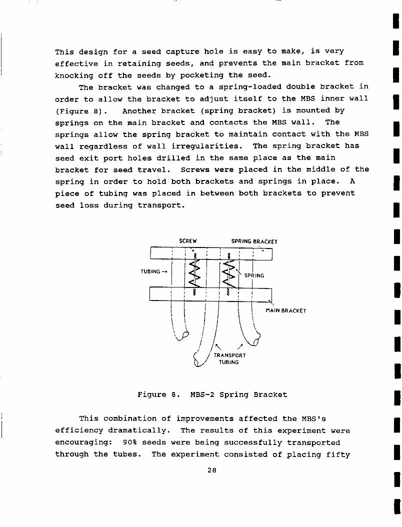
The bracket was changed to a spring-loaded double bracket in order to allow the bracket to adjust itself to the MBS inner wall (Figure 8). Another bracket (spring bracket) is mounted by springs on the main bracket and contacts the MBS wall. springs allow the spring bracket to maintain contact with the MBS wall regardless of wall irregularities. The spring bracket has seed exit port holes drilled in the same place as the main bracket for seed travel. Screws were placed in the middle of the spring in order to hold both brackets and springs in place. A piece of tubing was placed in between both brackets to prevent seed loss during transport.
The
SCREW SPRING BRACKET
Figure 8. MBS-2 Spring Bracket
This combination of improvements affected the MBS's efficiency dramatically. The results of this experiment were encouraging: 90% seeds were being successfully transported through the tubes. The experiment consisted of placing fifty
28
I I I I I I I I I I I I I I I I I I I
I I I I I I I I I I I I I I I I I I I
seeds in the MBS and rotating it until the seeds were held in place by the seed capture holes. with the spring bracket and a burst of air was applied from outside the MBS into the seed capture holes forcing the seeds into the transport tubes and out of the MBS.
A row of seeds was then aligned
ExDeriment 4. Tests were conducted to find the best way to distribute the air flow within the MBS to agitate the seeds toward the seed capture holes. The best results were obtained when two air lines entered the MBS to cause a circular flow along the inner wall. This flow is similar to the one used for MBS-1.
The new air flow caused the seeds to be captured by the holes quickly and efficiently. This allows the MBS to be rotated faster while maintaining a high percentage of successfully transported seeds. Even though the seeds were captured successfully, some dead zones did appear in the MBS. ( A dead zone is an area where the air flow strength is not sufficient to successfully agitate the seeds, therefore seeds in these areas would not move.)
Results to Date
Good results were obtained from the final tube transport MBS
seeder. The system separates and transports seeds quickly and accurately. This method of separating and transporting seeds merits further research and development.
Recommendations for Future Development
A recommended improvement is to get a stronger circular air flow within the MBS to decrease the probabilities of dead zones. Also, a more proficient rotating system is desirable.
29
nc
MINNOW BUCKET THREE (MBS-3)
pts and Desisns
The design of MBS-3 had originally intended using air as the pressure generator. Further examinations of the problems and experiments conducted with the design proved that water was a better choice for seed separation. By using water, the speed at which the seeds moved, both within the MBS and the transport tubes, was greatly reduced. This is important both in the optical detection of a seed and in the prevention of damage to the seed during transport. A wet MBS also allows the seeds to germinate before planting thus almost insuring plant growth.
water input tube, a cylinder, transport tubes, and end effectors. Seeds are transported in the water medium from a central storage
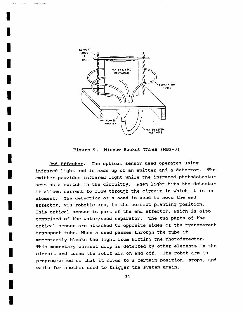
container to the funnel adaptor at the bottom of the MBS. The funnel adaptor is used to ensure adequate seed movement within the cylinder. The MBS is also used in an upright position to allow the funnel to be effective (Figure 9). In space the water flow within the cylinder will not depend on the orientation of the MBS. The cylinder is transparent, providing better observation of seed movement. Several holes were drilled in the wall of the cylinder and transport tubes were inserted into them. These tubes have an inner diameter that only allows one wheat seed to pass through lengthwise at any given time. After a seed enters the transport tube it proceeds through to the end effector which controls final seed placement and planting. This end effector is attached to a robotic arm which positions it for seed planting.
The actual design of this seeder involves a large seed and
30
I I I I I I I I I I I I I I I I I I I
I I I I I I I I I I I I I I I I I I I
SUPPORT
WATER & SEED CONTAINER
INLET HOSE
Figure 9. Minnow Bucket Three (MBS-3)
End Effector. The optical sensor used operates using infrared light and is made up of an emitter and a detector. The emitter provides infrared light while the infrared photodetector acts as a switch in the circuitry. When light hits the detector it allows current to flow through the circuit in which it is an element. The detection of a seed is used to move the end
effector, v ia robotic arm, to the correct planting position. This optical sensor is part of the end effector, which is also comprised of the water/seed separator. The two parts of the optical sensor are attached to opposite sides of the transparent transport tube. When a seed passes through the tube it momentarily blocks the light from hitting the photodetector. This momentary current drop is detected by other elements in the circuit and turns the robot arm on and off. preprogrammed so that it moves to a certain position, waits for another seed to trigger the system again.
The robot arm is stops, and
31
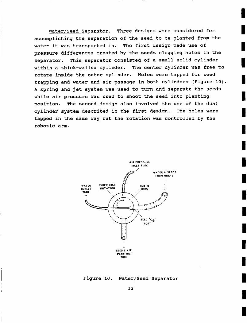
Water/Seed Separator. Three designs were considered for accomplishing the separation of the seed to be planted from the water it was transported in. The first design made use of pressure differences created by the seeds clogging holes in the separator. within a thick-walled cylinder. The center cylinder was free to rotate inside the outer cylinder. Holes were tapped for seed trapping and water and air passage in both cylinders (Figure 10). A spring and jet system was used to turn and separate the seeds while air pressure was used to shoot the seed into planting position. The second design also involved the use of the dual cylinder system described in the first design. The holes were tapped in the same way but the rotation was controlled by the robotic ann.
This separator consisted of a small solid cylinder
. . I '
, , * I * # 8 ,
1 :
Figure 10. Water/Seed Separator
32
I I I I I I I I I I I I I I I I I I I

I I I I I I I I I I I I I I I I I I I
The third design continuously operates and thus requires no optical sensor as in the second design. It operates using two separate disks connected by a rod. The smaller disk's rotation is controlled by a motor and in turn creates a back-and-forth movement in the larger disk. The larger disk has holes tapped for seed trapping and water and air passage, but the angle at which these holes are drilled is dependent on the radii of the two disks.
Results to Date
ExDeriment 1. The purpose of this experiment was to determine how well seeds could be separated using the MBS-3
design. This first experiment was done using air as the medium for seed transport. Approximately fifty seeds were placed into the MBS-3 and one transport tube was used to allow seeds to escape from the cylinder. A number of holes smaller than the seeds were also drilled through the cylinder wall to allow air flow. The MBS was placed in an upright position and air was blown through the funnel attachment. Subsequent experiments were done using several escape tubes.
very violently. experiments and several seeds passed through the escape tubes. Unfortunately, the seeds passed through the tubes very quickly
and one right after another at certain times. The conclusion from this experiment was that another transport medium was needed to slow seed transport within the cylinder and through the tubes.
The air blew the seeds around the inside of the cylinder Seeds stuck to the smaller holes as in previous
ExDeriment 2. The purpose of this experiment was to test water as the new medium for the MBS-3 design. was used as in the previous experiment. The modifications included a change in transport medium (air to water) and a five more transport tubes for a total of six.
The same procedure
3 3
Seeds were moved around the interior of more gently than in the previous experiment. through the transport tubes more slowly than
the cylinder much They also passed
when air was used. A problem that developed involved the clogging of the exit holes within the cylinder. When a large number of seeds were placed inside the MBS-3, seeds clogged the inlet to the escape holes. This was usually caused by one seed hitting the exit holes sideways and being held there by the pressure gradient. of holes was very random, although an increase in the number of seeds within the cylinder caused a slight increase in the number
Clogging
of clogs.
ExDeriment 3 . Two different tests were done to compare time to number of seeds escaped and the amount of clogging using the MBS-3. The set up was the same as in experiment two. The number of seeds in the MBS was determined at the beginning of the
experiment. In the first test the time for a specific number of seeds to escape was measured. The time required for ninety percent of the number of seeds initially placed inside the MBS
was chosen to measure time of escape. This number was chosen because the remaining small number of seeds usually took a long time to find an exit hole. Fifty and twenty-five seeds were used in the experiments due to the size of the MBS used in the experiments.
In the second set of tests a specific amount of time was chosen and the number of seeds that escaped was counted. For both experiments the number of clogs was counted and corrected. This was done by momentarily stopping water flow through the tube affected. This allowed the seeds to float off into the cylinder.
Both procedures gave identical results. As the number of seeds was increased at the beginning of the experiment, the rate of escape also increased. When fifty seeds were placed in the cylinder, as opposed to twenty-five, the times for ninety percent
34
I I I I I I I I I I I I I I I I
I I
m
I I I I I I I I I I I I I I I I I I I
escape were approximately ninety seconds and sixty seconds respectively. The number of clogs varied unpredictably, only slightly higher with fifty seeds than twenty-five.
Experiment with Water/Seed Separator. The purpose of this experiment was to test the design of the water/seed (W/S) separator. The water/seed separator was connected to the MBS-3 via water/seed transport tubes. Air pressure tube was also connected to the W/S separator and to a positive air supply. The MBS was set up and operated as in experiment two. The W/S separator was rotated by hand when a seed entered the seed port.
seal. Consequently a large amount of water leaked out from the air/seed planting tube. Except for the leakage the design was effective in moving the seed from the water/seed transport tube and out through the air/seed planting tube.
The crude materials used did not allow for a water tight
Recommendations for Future Develooment
The water MBS constructed and tested in these experiments performed well. Several problems were encountered with both MBS- 3 and the end effector. The clogging of seeds around holes was unpredictable. A mechanism for preventing clogging or correcting it needs to be investigated. A funnel design for the exit hole inlet was tried in later experiments, but the extent to which
this prevented clogging was not clear. A simple method for declogging was also devised in these later experiments. By stopping flow through the exit tube effected, the seeds would float away from the hole, thus declogging the exit.
The results for the W/S separator were also promising. The main problem was leakage, but this could be amended with the use of higher quality of materials in its construction. of MBS-3 and the W/S separator was successful in planting seeds into seed cassettes with the use of the robotic arm.
The coupling
35
ELECTRICAL SEEDERS
ConceDts and Desians
Upon completion of the Fall Semester, several goals were established for the Electrical Seeder Division final project. The shape of the electrodes needed to be configured to move the seeds in the desired direction. The propagating medium for the electric field was chosen to be air to minimize the possibility of seed damage. The seeds should be separated to produce an optimal planting scheme. Also, the final design, fabrication, and testing would be completed by the end of the Spring Semester.
The underlying principle behind the Electrical Division's seeder is the use of electrical induction to separate and transfer seeds to the planting mechanism. An electrostatic generator was used to apply an electric field between two electrodes. The electrostatic device was a van de Graff generator, which provides approximately 300,000 Volts. The electric field induced dipoles on the seeds; the poles were then attracted to the opposite electrode. Therefore, this seeder uses the electric field to prepare the seeds for planting.
Electrode Shapes and Field Confiqurations. Electric charge applied to a metallic conductor produces an electric field. The electric field creates l'linesll, which map the orientation of the field. These electric field lines originate and terminate at right angles to an electrode. By varying the shape of the electrode, the resulting field also changes. The parameters controlled were field strength and orientation. Field strength is inversely proportional to area, therefore the field is strongest when originating from a point source. Field orientation was controlled by the shape of the electrode.
from the source, electric induction motors are seldom used. For seed separation small forces can be used, especially in a
Since electric fields are weak and dissipate with distance
36
I I I I I I I I I I I I I I I I I I I
I I I I I I I I I I I I I I I I I I I
microgravity environment. of a wire to wire electrode configuration. The electric field is at its strongest, and the resulting seed separation occurs rapidly. The field propagated in all directions around the charged wire, and only a small component terminated on the oppositely charged electrode. Also, the field lines were elliptical and moved the seeds but did not separate them.
electrode configuration. This configuration benefited from the strong field of the wire electrode, but the field termination at the curved electrode scattered the seeds along the arc of the curve. The seed separation was inadequate, and a useful collection apparatus would be difficult to construct.
The first electrode design consisted
Another electrode design consisted of a wire-to-curved plate
A flat plate-to-flat plate electrode configuration produced better results. Since the field lines aligned themselves linearly from plate-to-plate, the seeds were oriented perpendicularly to the electrodes. This proved to be the optimum condition for seed separation. Due to the large area of the plates, the generated field strength did not move the seeds efficiently.
plate electrode configuration. This design employed the field strength properties of the wire electrode with the alignment properties of the plate electrode. The field lines were generated by the w i r e e lectrode and w e r e terminated over t h e
large area of the plate electrode. along the length of the flat plate, which would allow an easier implementation of a collection device.
After deciding on the configuration of the electrodes, the optimum placement of the electrodes was the remaining problem. Since the field dissipates inversely with distance, our conclusion was that the electrodes should be in close proximity. The optimum distance for seed separation was approximately two inches.
The best results were achieved by a wire electrode-to-flat
The seeds were dispersed
37
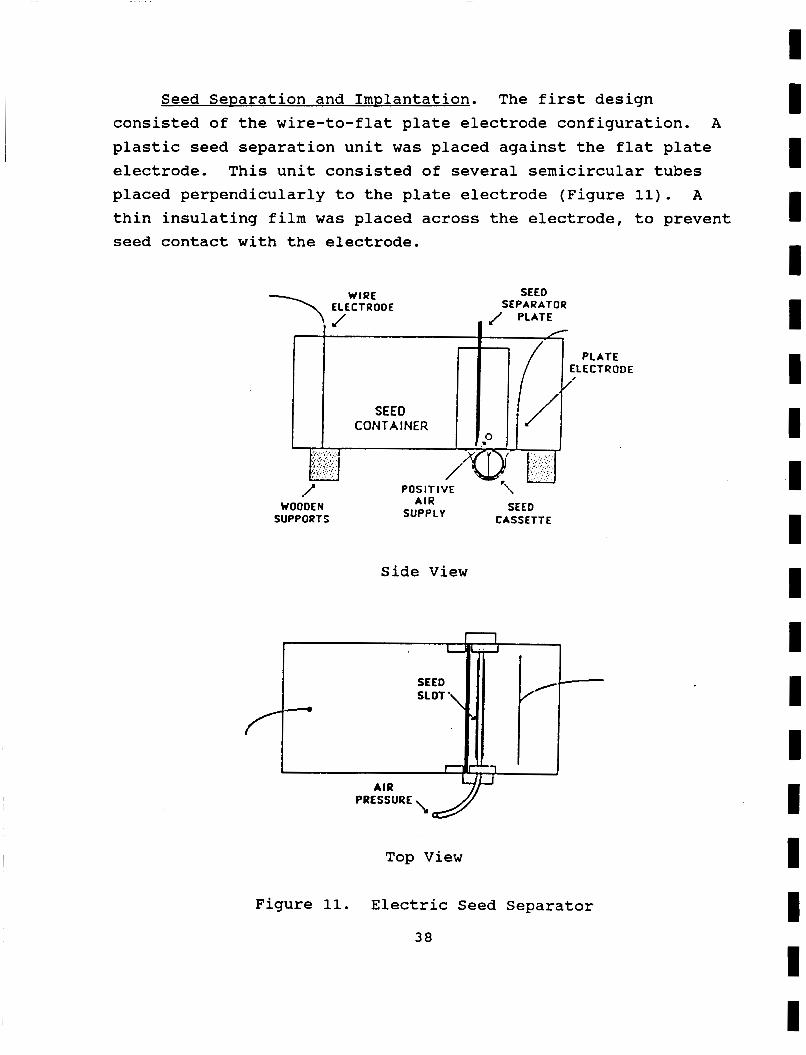
Seed SeDaration and Implantation. The first design consisted of the wire-to-flat plate electrode configuration. plastic seed separation unit was placed against the flat plate electrode. This unit consisted of several semicircular tubes placed perpendicularly to the plate electrode (Figure 11). A thin insulating film was placed across the electrode, to prevent seed contact with the electrode.
A
P L A T E ELECTRODE
WIRE \ ELECTRODE SEED
SEPARATOR J PLATE
I I
f I
I ' . . . .... ';: .:..:. ..i.._. . ..,/..,.I>.
..... . _ . /a u . .
P O S I T I V E -'\
SEED CASSETTE
A I R SUPPLY
1 WOODEN
SUPPORTS
Side View
L 1
SEED SLOT'
A I R
PRESSURE J Top View
Figure 11. Electric Seed Separator
38
I I I I I I I I I I I I I I I I I I I
I I I I I I I i I I I I I I I 1 I I I
This design produced fairly good results. The 3/8 in. semicircular tubing allowed several seeds to cluster in each tube. Also, the electric field was non-uniform, so each tube did not get an equal distribution of seeds. Several seeds entered into the separation unit, and the separation success rate was about 50%.
The next step after seed separation is seed planting. The planting scheme incorporated is the seed cassette planter. The seeds are forced between the two filtering contacts and suspended while receiving nutrients hydroponically.
Desiqn Immovements. The electric field provides an efficient way to separate seeds, although the electric force is insufficient for direct placement into the seed cassette planting unit. Therefore, a supplementary method for seed placement must be used. Seed spacing is also important, to allow ample light and sufficient nutrients for proper seed growth.
The problem of seed spacing was resolved by using an insulating gate .between the seeds and the collecting (flat plate) electrode. on both electrodes, and the opened gate allowed the seeds to migrate towards the collecting electrode. Therefore, the movement of the seeds could be controlled and clustering would be reduced.
concern. The electric field produces weak electric forces: these forces are able to separate the seeds but are incapable of forcing seeds into the cassette. An alternative method must be used to force the seeds into the cassette, once the seeds have been properly separated.
move the seeds into their respective places. The seeds were separated and transferred to the aperture of the seed cassette. Compressed gas was applied through a plastic tube with an opening along the cassette aperture.
The closed gate allowed electric charge to build up
Seed implantation into the cassette was the remaining
One alternative method consisted of using compressed air to
The amount of gas pressure
39
controlled the depth of seeds could be moved to
Results to Date
The results of the
penetration the optimum
experiments
into the cassette, and the depth.
showed that the electrostatic seed separation system may be useful for microgravity operation. The final design and experimentation produced a seeder with a fifty percent success rate, with one minute elapsed per cassette. In microgravity, several of the inhibiting factors will be diminished or eliminated. The seeder had some promising results, including a good success rate in a reasonable amount of time. Further research and development may produce a viable electrostatic seed separation system.
Inhibitins Factors. Humidity played a major role in seed
clumping. The field strength is. inversely proportional to conductivity. Air is an excellent medium because of its low conductivity. Water has a high conductivity, and a large presence of moisture dissipates the electric field between the electrodes. Charge migrates through the moist air and field strength dissipates accordingly.
Charge dissipation also occurred in other ways. The type of container used was composed of plexiglass. Plexiglass is a good insulator, but it is not perfect, and therefore charge remains on the container and the electrodes continue to lose charge. brackets, nuts, and bolts also held an amount of charge, depending on their conductivity. This process produces a multiplying effect; charge on the container attracts other charges, thus reducing the charge on the electrodes and the corresponding field strength. Charge also dissipated through the electric cables, which were made for smaller potentials and could not fully transmit the high voltage produced by the Van de Graff generator.
The
I I I I I I I I I I I I I I I 1 I I I
40
I I I 1 I I I I I I I I I I I I I 1 I
Another inhibiting factor was the presence of friction. Static and sliding friction between the seeds and the container prevent the electric forces from moving the seeds. Frictional forces are normal forces, which will be reduced in microgravity.
Recommendations for Future DeveloDment
Final Desicrn and Fabrication. After testing each system component separately, the final phase included the integration of field orientation, seed separation, and seed implantation. These elements were integrated into a final design and fabricated for testing.
electrode-to-flat plate electrode configuration. This electrode combination utilized the field strength of the wire electrode along with the collecting properties of the flat plate electrode. This configuration produced the proper field strength and orientation for successful seed separation and implantation. The plastic seed separator was discarded, because the force of the field was insufficient to overcome the slope of the separator. The alternative to the plastic separator was an insulating gate. The insulating gate is a dielectric that impedes the propagation of the field. This gate was placed between the wire electrode and the container opening. compressed air via a plastic tube into the cassette aperture where they were imbedded to the proper depth.
Once the electrostatic generator is turned on, charge is built up on the electrodes. When the restraining gate is raised, seeds are attracted to the flat plate electrode. Before seed collection at the flat plate, the seeds are held by the container opening and are imbedded in the cassette to the proper depth by the compressed gas. The restraining gate is then lowered so that no more seeds are allowed to enter the cassette. This procedure is repeated for the filling of other cassettes. In microgravity, the compressed gas flow would force the seeds into cassette, when the seeds crossed the flow path.
The final electrode configuration that was used was the wire
The seeds were propelled by
41
APPENDIX A
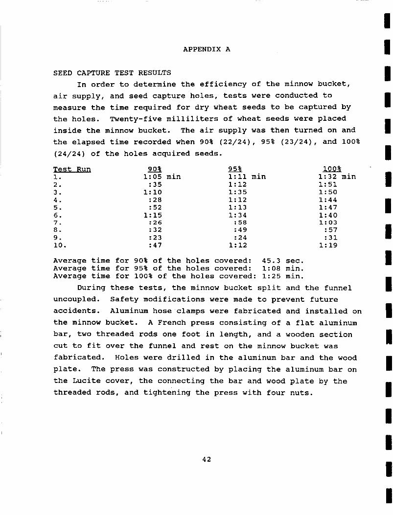
SEED CAPTURE TEST RESULTS In order to determine the efficiency of the minnow bucket,
air supply, and seed capture holes, tests were conducted to measure the time required for dry wheat seeds to be captured by the holes. Twenty-five milliliters of wheat seeds were placed inside the minnow bucket. The air supply was then turned on and the elapsed time recorded when 90% (22/24), 95% (23/24), and 100% (24/24) of the holes acquired seeds.
Test Run 1. 2. 3. 4. 5. 6. 7. 8. 9. 10.
90% 1:05 min : 35
1: 10 : 28 : 52
1: 15 : 26 : 32 : 23 : 47
95% 1:11 min 1: 12 1: 35 1: 12 1:13 1: 34 : 58 : 49 : 24
1: 12
100% 1:32 min 1: 51 1:50 1:44 1:47 1:40 1:03 : 57 : 31
1: 19
Average time for 90% of the holes covered: 45.3 sec. Average time for 95% of the holes covered: 1:08 min. Average time for 100% of the holes covered: 1:25 min.
During these tests, the minnow bucket split and the funnel uncoupled. Safety modifications were made to prevent future accidents. Aluminum hose clamps were fabricated and installed on the minnow bucket. A French press consisting of a flat aluminum bar, two threaded rods one foot in length, and a wooden section cut to fit over the funnel and rest on the minnow bucket was fabricated. Holes were drilled in the aluminum bar and the wood plate. The press was constructed by placing the aluminum bar on the Lucite cover, the connecting the bar and wood plate by the threaded rods, and tightening the press with four nuts.
42
I I I I I I I I I i I I II I I I I I
I I I I I I I I I I I I I I I I I I I
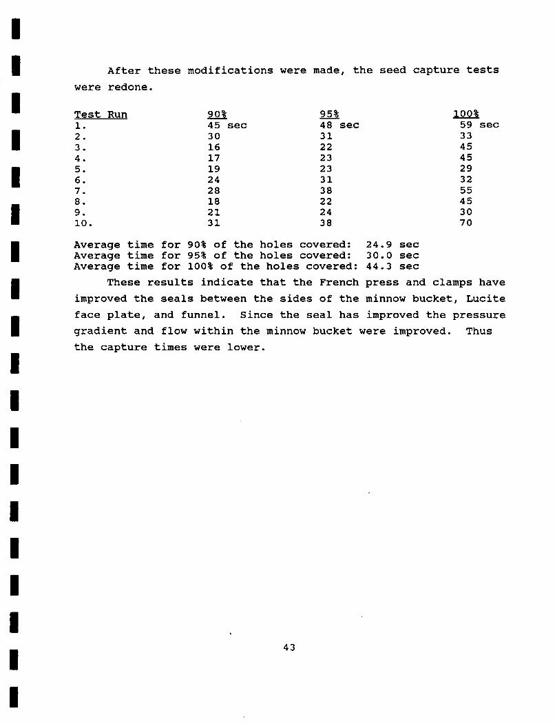
After these modifications were made, the seed capture tests were redone.
Test Run 1. 2. 3. 4. 5. 6. 7. 8. 9. 10.
90% 45 sec 30 16 17 19 24 28 18 21 31
95% 48 sec 31 22 23 23 31 38 22 24 38
100% 59 sec 33 45 45 29 32 55 45 30 70
Average time for 90% of the holes covered: 24.9 sec Average time for 95% of the holes covered: 30.0 sec Average time for 100% of the holes covered: 44.3 sec
These results indicate that the French press and clamps have improved the seals between the sides of the minnow bucket, Lucite face plate, and funnel. Since the seal has improved the pressure gradient and flow within the minnow bucket were improved. Thus the capture times were lower.
43
APPENDIX B
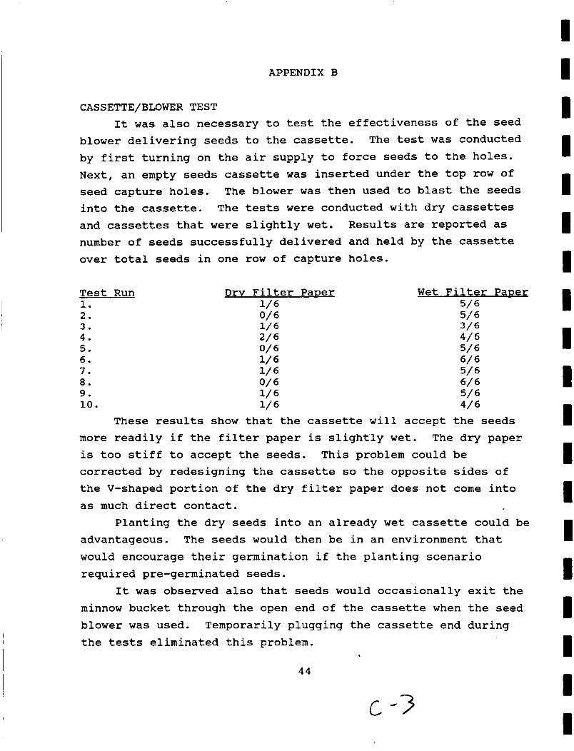
CASSETTE/BLOWER TEST It was also necessary to test the effectiveness of the seed
The test was conducted blower delivering seeds to the cassette. by first turning on the air supply to force seeds to the holes. Next, an empty seeds cassette was inserted under the top row of seed capture holes. into the cassette. The tests were conducted with dry cassettes and cassettes that were slightly wet. Results are reported as number of seeds successfully delivered and held by the cassette over total seeds in one row of capture holes.
The blower was then used to blast the seeds
Test Run 1. 2. 3. 4. 5. 6. 7. 8. 9. 10.
Wet Filter Paner 5/ 6 5/ 6 3/6 4/6 5/6 6/ 6 5/6 6/ 6 5/ 6 4/6
These results show that the cassette will accept the seeds more readily if the filter paper is slightly wet. The dry paper is too stiff to accept the seeds. This problem could be corrected by redesigning the cassette so the opposite sides of the V-shaped portion of the dry filter paper does not come into as much direct contact.
Planting the dry seeds into an already wet cassette could be advantageous. The seeds would then be in an environment that would encourage their germination if the planting scenario required pre-germinated seeds.
It was observed also that seeds would occasionally exit the minnow bucket through the open end of the cassette when the seed blower was used. Temporarily plugging the cassette end during the tests eliminated this problem.
44
C -3
I I I I I I I I I I I I I I I
I I I
a