i dedicate this to my wife for her unwavering...
TRANSCRIPT

1
VIRTUAL LOCKSTEP FOR FAULT TOLERANCE AND ARCHITECTURAL VULNERABILITY ANALYSIS
By
CASEY M. JEFFERY
A DISSERTATION PRESENTED TO THE GRADUATE SCHOOL OF THE UNIVERSITY OF FLORIDA IN PARTIAL FULFILLMENT
OF THE REQUIREMENTS FOR THE DEGREE OF DOCTOR OF PHILOSOPHY
UNIVERSITY OF FLORIDA
2009

2
© 2009 Casey M. Jeffery

3
I dedicate this to my wife for her unwavering support.

4
ACKNOWLEDGMENTS
I must acknowledge my advisor Prof. Renato Figueiredo for everything he has done for me
over the past six years. I have learned a great deal from him both in the classroom and from our
collaborations in various research and publication efforts. He is always available to provide
direction and exhibits incredible patience and understanding. He and Prof. José Fortes have done
a great job in directing the Advanced Computer and Information Systems (ACIS) lab while
encouraging the students to set high goals and then work hard to achieve them.
I would like to acknowledge Steve Bennett, who helped me in getting my first internship
with the Core Virtualization Research (CVR) group at Intel, as well as Tariq Masood, who
assisted me in achieving my first success in virtual lockstep during that internship. I also must
recognize Alain Kägi, Philip Lantz, Sebastian Schönberg, and my other co-workers in the CVR
group. I undertook this virtual lockstep work and other research projects that required advanced
system programming skills and knowledge of Intel x86 architecture, and without their support,
would not have learned what I needed to be successful at them.
Finally, I would like to thank my family, who have no idea what I do but support me
nevertheless. They are responsible for providing me with the necessary work ethic and continued
encouragement to be successful at whatever I apply myself to. My wife, in particular, is always
there for me at every step and has the benefit of knowing the path well, since she completed it
herself.
5
TABLE OF CONTENTS page
ACKNOWLEDGMENTS ...............................................................................................................4
LIST OF TABLES ...........................................................................................................................8
LIST OF FIGURES .........................................................................................................................9
ABSTRACT ...................................................................................................................................12
1 INTRODUCTION ..................................................................................................................13
Motivation ...............................................................................................................................13 Device Reliability ............................................................................................................14 Many-Core Architectures ................................................................................................15 Virtualization Technology ...............................................................................................16
Overview and Scope ...............................................................................................................17 Contributions ...................................................................................................................19 Dissertation Overview .....................................................................................................20
2 BACKGROUND AND RELATED WORK ..........................................................................22
Terminology ...........................................................................................................................22 Fault Tolerance Basics ............................................................................................................22 Fault Tolerance through Redundancy .....................................................................................24
Redundancy .....................................................................................................................24 Hardware Redundancy .............................................................................................25 Data Redundancy .....................................................................................................26 Network Redundancy ...............................................................................................27
Replica Coordination .......................................................................................................29 Requirements for Replication ...................................................................................29 Forms of Replication ................................................................................................30 Group Communication and Membership .................................................................34
Related Work in Fault Tolerance ............................................................................................38 Hardware Fault Tolerance ...............................................................................................39
Processor Logic ........................................................................................................39 Memory and I/O Devices .........................................................................................41
Software Fault Tolerance ................................................................................................43 Instruction Set Architecture .....................................................................................43 Operating System .....................................................................................................45 Middleware ...............................................................................................................46 Application/Compiler ...............................................................................................47
Case Study: Stratus ftServer architecture ........................................................................48 Fault Injection ..................................................................................................................49
Many-Core Architectures .......................................................................................................51 Network-on-Chip Architectures ......................................................................................51

6
Parallel Programming ......................................................................................................54 Virtualization and Logical Partitioning ..................................................................................54
Hardware Virtual Machines ............................................................................................55 Logical Partitioning .........................................................................................................57
3 PROPOSED FAULT TOLERANT ARCHITECTURE ........................................................61
Architecture Overview ............................................................................................................61 Replication Model Scope ................................................................................................61 Platform Partitioning and Virtualization .........................................................................62 Platform Monitoring ........................................................................................................66
Fault Model and Fault Tolerance Overview ...........................................................................66 Fault Models ....................................................................................................................66 Fault Tolerance Capabilities ............................................................................................68
Virtual Lockstep Overview .....................................................................................................72 Deterministic Execution ..................................................................................................72 Platform Partitioning Requirements ................................................................................74 Hypervisor Requirements ................................................................................................75
4 TEST PLATFORM OVERVIEW ..........................................................................................78
System Overview ....................................................................................................................78 KVM Hypervisor Overview ...................................................................................................80
KVM Components ...........................................................................................................81 KVM Implementation Details .........................................................................................83
Hardware Features and Limitations ........................................................................................84 Performance Counters .....................................................................................................85 Virtualization Hardware Extensions ................................................................................88 Interrupt Delivery ............................................................................................................89 Communication Infrastructure .........................................................................................90
Prototype Implementation Details ..........................................................................................90 Guest State Replication ...................................................................................................91 Guest Synchronization .....................................................................................................92 Deterministic Execution ..................................................................................................93
Prototype Limitations .............................................................................................................96 Layered Virtualization ............................................................................................................97
5 RELIABILITY MODEL AND PERFORMANCE RESULTS ............................................100
Prototype Test Platform ........................................................................................................100 Replication and Synchronization Overhead .........................................................................104
Replication and Reintegration Costs .............................................................................104 Virtual Lockstep Benefit Analysis ................................................................................109 Virtual Lockstep Performance Overhead ......................................................................114
6 FAULT INJECTION AND VIRTUAL PROCESSOR STATE FINGERPRINTING ........118
Fault Injection Model ...........................................................................................................118

7
Fault Injection Details ...................................................................................................118 Fault Propagation Analysis ............................................................................................119
Processor State Comparisons ................................................................................................120 Virtual Processor State Fingerprinting ..........................................................................121 Hashing Details .............................................................................................................122 Fingerprinting Optimizations ........................................................................................123
KVM Prototype Fault Injection ............................................................................................124 Fault Injection Overview ...............................................................................................124 Fault Injection Performance Results .............................................................................126 Virtual Processor State Fingerprinting Results .............................................................137
7 SUMMARY AND FUTURE WORK ..................................................................................148
Summary ........................................................................................................................148 Future Work ...................................................................................................................150
APPENDIX: FINGERPRINTING-BASED FAULT DETECTION RESULTS ........................152
LIST OF REFERENCES .............................................................................................................156
BIOGRAPHICAL SKETCH .......................................................................................................166

8
LIST OF TABLES
Table page 3-1 Replication configuration and capability summary. ..........................................................70
4-1 Prototype platform hardware and software specifications. ................................................80
5-1 Guest static snapshot replication size, image size, and state transfer time for a variety of guest operating systems. ..............................................................................................105
5-2 Definition of exit reason labels. .......................................................................................111
5-3 Virtual lockstep performance overhead summary. ..........................................................115
6-1 Hashing performance of various algorithms for a random 4KB page of memory. .........123
6-2 Fault injection target registers and their inclusion in the VMCS.....................................125
6-3 Control register CR0 bit descriptions. .............................................................................129
6-4 Control register CR3 bit descriptions. .............................................................................129
6-5 Control register CR4 bit descriptions. .............................................................................130
6-5 RFLAGS register bit descriptions. ...................................................................................136

9
LIST OF FIGURES
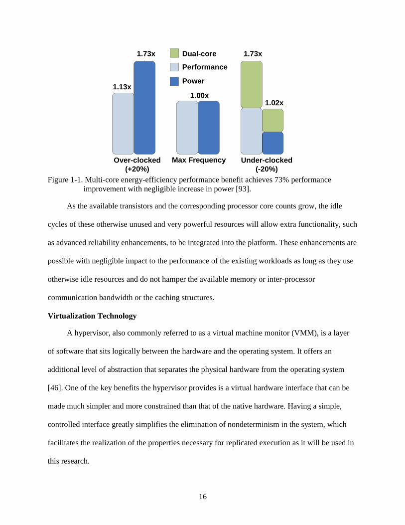
Figure page 1-1 Multi-core energy-efficiency performance benefit achieves 73% performance
improvement with negligible increase in power [93]. .......................................................16
2-1 Interstitial redundancy (shaded blocks) in a two-dimensional mesh network. The (4,4) configuration includes all spares and (1,4) configuration includes the two outermost spares.................................................................................................................28
2-2 Classic Paxos with four group members. The view change algorithm selects the primary and broadcasts it to all other members. The primary then chooses a value and attempts to get the other members to choose the same value and accept it. When successful, the final decision is written back to all members and returned. ......................36
2-3 Byzantine Paxos with four group members. The view change algorithm determines the primary without trusting the primary. The primary then chooses a value and attempts to get the other members to choose the same value and accept it. When successful, the final decision is written back to all members and returned. ......................37
2-4 Chandra-Toueg algorithm with four group members. All members send the primary a value/view pair. The primary makes the choice for the view and broadcasts to all members. It then awaits a majority of ack’s and records the decision if they are received. If a single nack is received, a new view is started with a new primary. ............38
2-5 Architecture of hypervisor-based duplex replication model. .............................................43
2-6 Stratus architecture with lockstepped processors and independent replicated I/O subsystem bridged with fault detection and isolation chipsets. .........................................49
2-7 Sample control flow for an EFI BIOS being logically partitioned at boot time. ...............58
2-8 Partitioned quad-core platform with one partition hosting an OS directly and the other partition hosting a type-I hypervisor that has two guest operating systems. ............59
3-1 Logically partitioned many-core platform with each partition hosting a hypervisor. The main partition hosts one or more guest virtual machines while the replica partition hosts a virtually-lockstepped replica of a single virtual machine. ......................63
3-2 Logically partitioned quad-core platform with each partition hosting a hypervisor. The main partition hosts a single guest virtual machine while the three replica partitions hosts virtually-lockstepped replicas of main guest. ...........................................64
3-3 Physical many-core processor arrangement options include single-socket, multi-socket, or networked systems. ...........................................................................................65
10
3-4 Fault detection inherent in virtual lockstep output value buffer. Divergence is detected when backup generates value that differs from the current head of the buffer. .................................................................................................................................69
3-5 Fault detection inherent in virtual lockstep input value buffer. Divergence is detected when backup requests input value for a different operation than is at the current head of the buffer........................................................................................................................71
3-6 VT-x transition latencies for five generations of Intel® Xeon® processors. ......................77
4-1 High-level overview of test platform used for virtual lockstep prototype development and testing. .........................................................................................................................79
4-2 High-level overview of KVM hypervisor architecture. .....................................................82
4-3 Interface diagram of the KVM hypervisor. ........................................................................84
4-4 Deterministic VM exit generation using performance monitor interrupts. ........................87
4-5 Circular bounded broadcast buffer with primary inserting at in and two backup replicas retrieving from out pointers. .................................................................................93
4-6 Deterministic execution and interrupt delivery with epochs defined by the deterministic VM exits. ......................................................................................................94
4-7 Deterministic execution and interrupt delivery with epochs defined by performance counter interrupt generation. ..............................................................................................94
4-8 KVM execution loop diagram [68]. ...................................................................................96
5-1 VM exits per second for various combinations of operating system and benchmark. ....107
5-2 Total bytes per second of nondeterministic data for various combinations of operating system and benchmark. ....................................................................................108
5-3 Total runtime for various combinations of operating system and benchmark broken down by time spent running in the guest and time spent in the hypervisor. ....................110
5-4 Break down of the VM exit reasons while executing the test workloads. .......................112
5-5 Percentage of total runtime spent in the hypervisor broken down by the specific exit reasons while executing the test workloads. ....................................................................113
5-6 Total run-time of primary and either one replica (dual-modular redundant), two replicas, (triple-modular redundant), or three replicas (quad-modular redundant) with a shared buffer size ranging from 5,000 entries to 80,000 entries. ..................................116
6-1 Robert Sedgewick hash function code. ............................................................................122

11
6-2 Fault injection failure distribution for control registers. ..................................................128
6-3 Fault injection failure distribution for segment registers. ................................................131
6-4 Fault injection failure distribution for system descriptor tables and the task register. ....132
6-5 Fault injection failure distribution for general purpose registers. ....................................133
6-6 Fault injection failure distribution for various system registers. .....................................134
6-7 Fault injection failure distribution for the RFLAG register. ............................................135
6-8 Average time to fault detection measured in deterministic VM exits. ............................137
6-9 Percent of trials in which fingerprinting-based fault detection detected the fault either before (better) or after (worse) than it was detected via I/O comparisons or system crash. The detection was concurrent for the remainder of the trials. ...............................138
6-10 Fingerprinting optimization showing first fields to indicate failure on average for all registers. ...........................................................................................................................141
6-11 Fingerprinting optimization showing first fields to indicate failure for CR0 register. ....143
6-12 Fingerprinting optimization showing first fields to indicate failure for the segment registers. ...........................................................................................................................144
6-13 Fingerprinting optimization showing first fields to indicate failure for the general purpose registers. .............................................................................................................145
6-14 Fingerprinting optimization showing first fields to indicate failure for the system registers. ...........................................................................................................................146
A-1 Fingerprinting optimization showing first fields to indicate failure for CR3 register. ....152
A-2 Fingerprinting optimization showing first fields to indicate failure for CR4 register. ....153
A-3 Fingerprinting optimization showing first fields to indicate failure for descriptor tables and task register. ....................................................................................................154
A-4 Fingerprinting optimization showing first fields to indicate failure for RFLAGS register..............................................................................................................................155

12
Abstract of Dissertation Presented to the Graduate School of the University of Florida in Partial Fulfillment of the Requirements for the Degree of Doctor of Philosophy
VIRTUAL LOCKSTEP FOR FAULT TOLERANCE AND ARCHITECTURAL VULNERABILITY ANALYSIS
By
Casey M. Jeffery
August 2009
Chair: Renato J. O. Figueiredo Major: Electrical and Computer Engineering
This dissertation presents a flexible technique that can be applied to commodity many-core
architectures to exploit idle resources and ensure reliable system operation. The proposed system
interposes a dynamically-adaptable fault tolerance layer between the hardware and the operating
system through the use of a hypervisor. It avoids the introduction of a new single point of failure
by incorporating the hypervisor into the sphere of replication. This approach greatly simplifies
implementation over specialized hardware, operating system, or application-based techniques
and offers significant flexibility in the type and degree of protection provided. The possible
levels of protection considered range from duplex replication to arbitrary n-modular replication
limited only by the number of processors in the system. The feasibility of the approach is
considered for both near- and long-term computing platforms and a prototype is developed as a
proof-of-concept and used to estimate the performance overhead and gather empirical data on
fault tolerance capabilities. A fault detection latency reduction technique is also proposed and
analyzed using the fault injection facilities provided by the prototype.

13
CHAPTER 1 INTRODUCTION
Motivation
The capabilities of the single-chip microprocessor have progressed at an astonishing pace
since Intel introduced the model 4004 chip more than 35 years ago. Numerous technological
hurdles have been overcome to maintain the steady march of Moore’s Law and advance from a
microprocessor with a mere 2,300 transistors to modern designs with more than a million times
that amount. One of the greatest challenges on the horizon for continuing such advancements
beyond the next decade is that of maintaining acceptable processor reliability.
The motivation of this work is to explore techniques of both assessing and improving the
reliability of general purpose processors through replicated execution that is inexpensive both in
terms of implementation costs and performance overhead. The ideas are based on well-
recognized aspects of future processor designs. The first is that as the size of transistors
continues to shrink, the reliability of individual transistors is unlikely to improve and at best will
remain constant. This means that a process technology that allows for a ten-fold increase in the
number of transistors on a device will increase the device-level error rate by at least the same
factor of ten. The second principle is that the paradigm shift from single core processors to dual-
and quad-core will continue so that even commodity computing platforms will have dozens or
possibly hundreds of cores.
The key target of the technique is improving processor-level reliability of many-core
platforms by transparently replicating execution across cores in response to signs of pending
uncorrectable errors. A small percentage of the cores are used to dynamically replicate execution
of cores that require additional redundancy, either because a high rate of faults is detected or
critical portions of code are being computed. Additionally, the model could be applied to systems
14
that have very high reliability requirements and/or are subject to much higher rates of faults due
to single event upsets, such as those used in the aerospace industry.
Device Reliability
The progression to nanoscale device sizes is impinging on fundamental physical limits and
bringing about new reliability issues to contend with such as an increase in single-event upsets
induced by radiation events and electromagnetic interference, extreme static and dynamic
transistor variability, and transistor performance degradation and wear-out [8], [13], [14], [28],
[51], [114]. These effects are expected to present a challenge regardless of the specific process
technology used [18].
For example, it is projected that the soft error rates of combinational logic will soon
approach the levels at which error protection mechanisms became necessary in memory devices
[20], [51], [106]. It is also forecasted that soft errors will account for a greater portion of total
system failures than all other means of failure combined [8]. The problem of soft errors has been
present since the dawn of digital electronics, but it has been most prevalent in memory devices
that can be protected much more easily than logic circuits [130].
The significant increase in transistor variability is the result of the use of sub-wavelength
lithography to pattern the device structures, as well as from the decrease in the number of dopant
atoms in the transistor channel. The patterning variation is expected to be dealt with through new
techniques such as extreme ultraviolet (EUV), imprint, or maskless lithography, although no
solution is yet in place [60]. The dopant variability is the result of an exponential decrease in the
number of dopant atoms required for each new generation of process technology. Modern 45-nm
CMOS technology has channel dopant levels on the order of 100’s of atoms while the 16-nm
technology, expected within the next decade, will require only 10’s atoms and result in a very
high level of transistor variability [13], [14].

15
Finally, there is the issue of device wear-out due to time-dependent dielectric breakdown,
electromigration, and thermal cycling [114], [126]. The resulting failures, termed intrinsic hard
failures, are permanent and decrease the long-term reliability of the devices. The model used in
[114] shows an increase in failures in time (FIT) of more than 300% on average when scaling
from a 180-nm process technology to a 65-nm process. Such an increase in the rate of hard faults
results in the wear-out phase of the device occurring much earlier and shortening the usable
lifetime of the part.
Many-Core Architectures
The semiconductor industry has recently transitioned to a multi-core paradigm to make use
of the huge number of transistors that can now be placed on a single chip. The multi-core
approach allows for improved overall performance while side-stepping the power and heat
dissipation limitations of continued clock frequency scaling [14], [113]. The energy efficiency
advantage of multi-core architectures in depicted in Figure 1-1 from [93] where the cost of 73%
more power is necessary for overclocking to achieve a mere 13% performance improvement
while a dual-core system is capable of a 73% performance improvement with negligible
additional power. The industry roadmaps anticipate this approach continuing on to many-core
designs that have dozens or even hundreds of possibly heterogeneous cores on a single die [10],
[14], [60], [119].
Of course, the limiting factor in realizing overall performance improvements with many-
core architectures is the ability of software to extract sufficient parallelism to take advantage of
all the cores concurrently. Unfortunately, parallel programming has historically proven very
challenging and is expected to remain so. The move from instruction-level parallelism to thread-
and application-level parallelism allows for better use of multiple cores, but there will inevitably
be unused processing cores sitting idle [41].
16
Dual-core
Performance
Power
1.73x
1.13x1.00x
1.73x
1.02x
Over-clocked(+20%)
Max Frequency Under-clocked(-20%)
Figure 1-1. Multi-core energy-efficiency performance benefit achieves 73% performance improvement with negligible increase in power [93].
As the available transistors and the corresponding processor core counts grow, the idle
cycles of these otherwise unused and very powerful resources will allow extra functionality, such
as advanced reliability enhancements, to be integrated into the platform. These enhancements are
possible with negligible impact to the performance of the existing workloads as long as they use
otherwise idle resources and do not hamper the available memory or inter-processor
communication bandwidth or the caching structures.
Virtualization Technology
A hypervisor, also commonly referred to as a virtual machine monitor (VMM), is a layer
of software that sits logically between the hardware and the operating system. It offers an
additional level of abstraction that separates the physical hardware from the operating system
[46]. One of the key benefits the hypervisor provides is a virtual hardware interface that can be
made much simpler and more constrained than that of the native hardware. Having a simple,
controlled interface greatly simplifies the elimination of nondeterminism in the system, which
facilitates the realization of the properties necessary for replicated execution as it will be used in
this research.

17
The use of hypervisors has risen dramatically in the past decade as the capabilities of
processors and the complexity of software have progressed. As one example, over 85% of
companies with between 100 and 5,000 employees claim to have deployed some form of
virtualization technology [36]. Virtualization of the hardware allows for use cases such as server
consolidation, data isolation, program testing and development, cross-platform compatibility,
and others [98], [127]. In the near future, every major operating system will have an integrated
hypervisor with Linux incorporating the KVM hypervisor in version 2.6.20 and Microsoft®
integrating Virtual PC and Hyper-VTM hypervisors into Windows 7® and Windows Server®
There have also been a number of advancements in the area of virtualization that have
made it easier for developers to write a hypervisor and significantly decreased the associated
performance overhead to the point of approaching native hardware speeds [1], [120]. Currently
there are hardware-based virtualization extensions integrated into every major processor
architecture, as well as in peripheral devices such as network cards. Soon, at least in the
enterprise computing sector, the entire platform will be virtualization aware and practically every
server manufactured will have the necessary support for the virtual lockstep replication model
presented in this dissertation.
2008
R2, respectively.
Overview and Scope
There are numerous levels at which to apply replication in an effort to improve system
reliability. The replication model considered in this dissertation is a novel, hybrid approach that
is a form of virtual lockstep. It provides operating system replication across an arbitrary number
of processor cores under the control of a hypervisor. The hypervisor itself is also replicated so as
to avoid the introduction of a new single point of failure. The key benefit of the hypervisor-based
approach is that it can be done purely in software, so as to work with commodity processor

18
architectures, yet it can be enhanced to take advantage of virtualization-specific hardware
extensions such as Intel®
The generalized virtual lockstep replication model proposed provides a means of coping
with both transient and intermittent faults in the processor cores that are caused by single-event
upsets and device marginality. It is the first such model to allow for the incorporation of varying
degrees of fault tolerance, up to and including arbitrary and possibly malicious Byzantine
failures. It is meant to ensure correct functionality while minimizing redundancy overhead and
avoiding the need for complex hardware, operating system, or application changes. The types of
systems targeted for this approach are multi- and many-core PCs and low- to mid-range servers,
as well as specialized systems with additional reliability requirements. Such systems have
historically not supported lockstepped execution and are not amenable to replication of the entire
physical system, as has historically been done in high-end mainframes.
Virtualization Technology (also referred to as VT-x or VMX) to
improve capabilities and reduce the performance impact [57], [68].
Additionally, a novel method of enhancing the fault detection capabilities, and
correspondingly the availability, of the system is proposed. The virtualization-based architecture
is leveraged as a means of reducing fault detection latency through monitoring of virtual
processor state hashes. The virtual state is hashed into unique fingerprints that are compared at
regular intervals to detect a divergence between replicas before the error propagates to the output
of the processor. This is similar to techniques which hash the physical state of the processor, but
it does not require complex, costly, and legacy-incompatible additions to the processor
architecture. The early fault detection mechanism is shown to improve the overall system
availability by increasing the likelihood that a rollback recovery is initiated before the error is
recorded to the saved state in the system checkpoint.
19
Finally, a mechanism for analyzing the architectural vulnerability factor of a processor is
presented. The fault injection capabilities inherent in a virtualized system are utilized to induce
faults into the bits of the processor registers and the propagation of the fault is monitoring by
tracking the subsequent state of the processor. This is similar in application to previous
techniques such as RTL fault injection, hardware radiation testing, and analytical fault modeling.
The goal of the technique is to assess the sensitivity of various processor structures to single- and
multi-bit single-event upsets, as well as intermittent faults and stuck-at faults caused by device
marginality and wear-out.
This technique of monitoring the architectural vulnerability is used to quantitatively
analyze the performance of the proposed early fault detection mechanism and to further optimize
the algorithm by determining the most sensitive subset of the processor state for each register/bit
combination. It is shown that only a small subset of the total virtual processor state is necessary
in the fingerprint to maintain a high level of fault detection. A second optimization is suggested
in which either custom hashing hardware or idle processor resources may be used to improve the
hashing performance of the fingerprinting technique by seamlessly integrating into the existing
virtualization hardware.
Contributions
In summary, the specific topics addressed in this dissertation and the corresponding goals
are summarized as follows:
• Define the first generalized virtual lockstep model in which the platform is logically or physically partitioned and the hypervisor is incorporated into the sphere of replication. The model is meant to be agnostic to the specific type of hypervisor, communication protocol, or computing platform used.
• Demonstrate the ability of the proposed architecture to extend the degree of
replication previously considered by lockstep architectures by allowing for a variable degree of protection ranging from dynamic duplex replication in which a

20
single backup is tied to one or more primary cores to arbitrary n-modular configurations with the possibility of supporting Byzantine protocols.
• Develop a proof-of-concept test platform for virtual lockstep using a full-featured
hypervisor and quantitatively analyze the performance impact of the proposed model over non-replicated execution. This is the first virtual lockstep implementation with the features presented in the model. It is a software-only approach that relies on hardware extensions for virtualization of Intel®
processers and extends the open source KVM hypervisor.
• Implement a novel, low-overhead fault detection latency reduction technique that takes advantage of the virtual processor state maintained by the hypervisor to generate unique fingerprints that often detect faults much earlier than relying on output comparisons or the inherent detection capabilities of virtual lockstep. This is a unique form of processor state fingerprinting that is practical given that it does not require hardware modification but may be easily enhanced by assigning idle, general purpose compute resources to perform the hashing.
• Define a fault injection protocol to be used as a test harness for quantitatively
analyzing the capabilities of the fault detection and recovery capabilities of the prototype. The fault injection capabilities double as an original means of assessing the architecture vulnerability factor of a processor. This can be used to obtain accurate fault sensitivity data for real hardware and allows for tuning of the protection mechanisms.
Dissertation Overview
The remainder of the dissertation is organized as follows: Chapter 2 gives an introduction
to the basic concepts in fault tolerance, redundancy, and replica coordination, as well as a
literature review encompassing previous work in both hardware- and software-based approaches
to fault tolerance. A brief overview, including the current state of the art, is also provided for
relevant work in the areas of many-core processor architectures and virtualization technology.
Chapter 3 introduces the generalized virtual lockstep model and fault tolerance mechanisms and
goes on to show how they can be applied to current and future computing platforms. The details
of a prototype test platform that implements the proposed model are given in Chapter 4. Chapter
5 summarizes the benchmarks used in evaluating the performance of the prototype, as well as the
additional modeling and test cases used to evaluate the practicality of the approach. The fault

21
injection mechanism and fault detection latency reduction technique are covered in Chapter 6.
Finally, Chapter 7 summarizes the goals of the research and the steps in achieving them. It also
provides more insight into the future applicability of the model and additional research that may
be done to further enhance the benefits derived from the approach.

22
CHAPTER 2 BACKGROUND AND RELATED WORK
Terminology
The terminology used in discussing reliability is often overloaded and is not always
unambiguous. For clarification, a distinction is made between defects, faults, and errors. The
term defect is used to reference a permanent, physical imperfection in a device that is caused at
fabrication by a processing error. The ability of a part to work correctly in the presence of defects
is called defect tolerance. If a defect occurs in a device that is being accessed and consistently
results in incorrect data being calculated and returned, it is said to result in a permanent or hard
fault. It is also possible for the defect to result in a weak device that will fail intermittently and/or
have very poor performance; this is called a parametric or intermittent fault.
A failure may also occur without being the result of a physical defect. The extraordinarily
small size of the circuitry makes it susceptible to soft errors as a result of environmental effects
such as cosmic rays, alpha particles, and neutrons. This type of fault is not permanent and is
referred to as a transient or soft fault. The next time the memory bit or logic gate is used it will
function correctly and does not require additional action.
If a fault can be corrected either by a mechanism in the hardware or through the use of
software, then the system is said to have fault tolerance. If however a fault occurs that cannot be
corrected, it will fall into one of three categories: it will cause an error that is seen by the user, it
will become benign as a result of being masked or in a bit that is never used, or it will remain
undetected as silent data corruption (SDC) waiting to be uncovered at a later time.
Fault Tolerance Basics
The challenge of providing fault tolerance in computing systems is as old as the field itself.
There has been an enormous amount of research conducted over the years with the goal of

23
providing dependable system operation. The term dependability is used as it encompasses not
only the reliability of the system, but also the availability, safety, and maintainability. Reliability
is defined as the probability that a system functions correctly for time t and is based on the rate
of errors seen over T, the lifetime of the part. Formally it is written as follows: R(t) = Prob(T > t)
[22]. The mean time to failure, MTTF, is defined as the expected time the system will last until a
failure occurs and is calculated as
MTTF = E[T] = ∫∞
0
dtR(t) . (1)
The availability is related to the reliability in that it is the ratio of the MTTF to the MTTF
plus the mean time to repair (MTTR). The term safety means that the failures that do occur do
not permanently corrupt the data being processed or the underlying system itself. And finally, the
maintainability of a system is determined by the ease or speed with which it can be repaired
when a failure does occur.
MTTRMTTF
MTTFtyAvailabili+
= (2)
An important aspect to consider when designing for fault tolerance is the set of possible
failure modes that must be considered. The most straightforward is a crash failure in which the
system operates correctly up until the time of the failure and then fails in a detectable fashion.
Other possibilities include an omission failure where the system does not respond to a request, a
timing failure where the response does not occur in a timely manner, or a response failure in
which the value returned is incorrect or the result of an invalid state transition. Finally, the most
difficult type of failure to contend with is an arbitrary failure that is caused by the system
producing arbitrary, possibly malicious responses.
24
Fault Tolerance through Redundancy
There are numerous techniques available for providing fault tolerance by either protecting
the system from the occurrence of errors or allowing for quick recovery from them. The focus of
this dissertation is on several forms of redundancy that have historically been shown to achieve a
high level of fault tolerance with a reasonable amount of overhead in terms of performance and
cost. Although other techniques are not considered explicitly, it is possible in many cases to
incorporate them into the proposed model to achieve additional benefits with a corresponding
increase to the cost and complexity of the system. Examples include various forms of
checkpointing with rollback recovery, which allow for fast system recovery to a previously saved
state, and software rejuvenation approaches that periodically refresh the state of the guests to
flush out any undetected faults that may have occurred [17], [19], [69], [84], [92], [111].
Redundancy
Many forms of redundancy are possible, and may include any combination of additional
hardware and/or software resources. The general hardware approach consists of replicating all or
part of the physical system and incorporating fault detection and reconfiguration logic. The extra
resources may either be used actively by applying them concurrently with execution on the
original base system or passively by having the base system periodically update the state of the
backups but only enable them when the base system has failed.
The general software approach is to make use of information coding techniques, such as
parity bits that are calculated for each piece of data being processed and then appended to the
data so as to be validated by the receiver. It is also possible for redundancy to be implemented in
time through repeated execution of the same operation. The software can replicate the execution
either temporally by executing it on the same hardware each time or spatially splitting the
execution concurrently across different pieces of hardware.

25
Hardware Redundancy
The most basic redundant model is a simple, parallel system with active replication. All
redundant units are enabled at all times, which ensures all replicas are always up-to-date and the
system as a whole is operational as long as any single unit is still functional and the error
detection logic is capable of reconfiguring the system. The reliability of this simple, parallel
system is calculated as
( ) ])(11)[()( 1det
+−−= Nectionparallel tRtRtR (3)
where Rdetection
There are a number of limitations in a simple active replication scheme, including the
inability to ensure a seamless failover when a unit in the system goes down and the high cost of
maintaining a large number of units online at all times. A powerful technique for providing
seamless failover is one in which the units are not only replicated but a voter is used to
consolidate the outputs into a single value. As long as a majority of the units in the system are
functioning correctly, the failure of a unit will not be observable.
(t) is the reliability of the error detection logic and N is the number of spare units
in the system, which leads to a total of N+1 units. It is clear from this equation that the
performance of the error detection logic should not be overlooked given that it is a gating factor
on the overall system reliability.
In triple modular redundancy (TMR), for example, three units execute in parallel and the
resulting output is determined by a majority vote. In general, this type of system is known as N-
modular redundancy and the reliability is described by the equation for an M-of-N configuration
as
[ ] iNiN
MivoterNlofM tRtR
iNtRtR −
=−− −
= ∑ )(1)()()( . (4)

26
It is a well-known effect of N-modular redundant systems that the overall reliability
actually decreases for low levels of individual unit reliability. This means that a single unit is
generally a better choice when the unit reliability at or below approximately 50%. For relatively
high reliability units, the N-modular redundancy approach can achieve significant reliability
gains.
A technique for reducing the overhead in an actively replicated system is to avoid having
all units online concurrently. Instead, the spare units are only powered on when necessary, such
as to resolve a discrepancy seen in the output of the active systems. For example, the TMR
system could be implemented as a duplex or dual modular redundant (DMR) system that
activates a spare unit only when the outputs of the active units are not in agreement. Not only
does this reduce the cost in terms of power consumption, but it increases the lifetime of the units
that are powered down.
Data Redundancy
Another technique for providing redundancy is through embedding extra bits of
information into the system. This is achieved through the use of information coding techniques
that apply an algorithm to each unit of data to generate a codeword with additional information
that can be used to detect, and in some cases correct errors that occur. The level of protection is
improved by increasing the distance between codewords or number of bits by which valid bit
patterns are separated. If valid codewords are separated by a single bit, it is possible to detect an
error, whereas if the separation is increased to two bits, it is possible to correct the error in any
single bit position.
The most basic forms of data redundancy are parity codes, the simplest of which is a single
parity bit. The parity bit is added to ensure either an even or odd number of 1’s in the bits of the
data. A more powerful class of codes is known as Hamming codes. These codes function by

27
overlapping the parity bits. In the general algorithm, the parity bits are placed at bit positions
corresponding with powers of two (i.e. 1, 2, 4, 8, etc.). The parity bit at position 2n
It is also possible to apply parity at a coarser granularity than at the bit level. The
Redundant Array of Independent Disks (RAID) and Redundant Array of Independent Memory
(RAIM) techniques applied to hard disk and main memory subsystems, respectively are
examples of this. There are numerous algorithms defined for various levels of RAID with the
simplest being RAID level-1 where the data are mirrored across two devices. A more complex
configuration that is often used in practice is level-5. In RAID level-5, blocks of data defined by
the stripe size are interleaved among N devices where N is at least three and 1/N of the total
storage area is reserved for parity. All of the parity data are not stored on a single device,
however. Instead, the parity blocks are distributed equally among all devices to improve the
performance of the system and balance the wear across all devices.
will then be
calculated based on the bits at all positions for which that bit n is set in the binary representation.
The basic Hamming codes are designed to allow for the correction of a single error or the
detection of any double-bit error within a codeword. There are a number of extensions that can
be applied, such as adding an additional parity bit to those applied in the normal Hamming
algorithm. Such an algorithm is capable of correcting a single bit error while detecting any
double-bit error or detecting a tripe-bit error.
Network Redundancy
Many of the forms of data redundancy can be used to detect and possibly recover from
faults introduced in the communication network linking system, but they are ineffective in
protecting against complete failure of the link. There are however techniques available for
achieving resiliency in the communication structures. For the two-dimensional mesh, which is
the form of communication network considered in this research, interstitial redundancy provides

28
spare nodes linked into the primary mesh. The degree of redundancy is typically either a single
spare for every four nodes, known as (1,4) configuration, or a spare for every node, known as a
(4,4) configuration. The spare nodes are placed within the mesh, as shown in Figure 2-1, and can
be switched in when a node or link fails.
Figure 2-1. Interstitial redundancy (shaded blocks) in a two-dimensional mesh network. The (4,4) configuration includes all spares and (1,4) configuration includes the two outermost spares.
Another method of providing fault tolerance in the network is through fault tolerant
routing. It does not require explicitly redundant resources, although it is necessary to have
additional logic built into the network stack and may be practical only with redundant virtual
channels in the system to reduce contention in the face of faulty links.
One of the most common fault-tolerant routing protocols for mesh networks is origin-
based routing which, in its most basic form, can tolerate N-1 failures in an N x N network [76].
The fault-tolerant origin-based routing algorithm is rather complex, but the basic steps of the
algorithm are as follows. First, it maps out faulty nodes and determines the smallest square
region that will encompass those nodes. The entire square region is considered faulty to simplify
the routing algorithm. It then routes towards the destination on the sub-network directed towards
the origin node until it reaches a node in the outbox, which is defined as having the coordinates

29
(x,y) such that 0 ≤ x ≤ xd and 0 ≤ y ≤ yd where (0,0) is the origin and (xd,yd
Replica Coordination
) is the destination.
Once in the outbox, the routing continues towards the destination until it reaches a safe node,
which is a node that can be reached from the destination on the sub-network directed away from
the origin node. Finally, once at the safe node, the routing can proceed without impediment to
the destination node.
If the form of redundancy used includes multiple replicas, it is important to be able to
coordinate them in an appropriate manner. This is a challenging task that has been a focus of
research for decades. The key requirements of replication and the basic communication and
consistency models for ensuring it have been solved for the most part, but there is a significant
amount of work remaining in optimizing the performance and reducing the cost of the systems,
as well as in handling more challenging models such as those that allow for multi-threaded
replicas. This section provides an overview of the basic types of replication and the fundamental
properties that must be maintained for coordination.
Requirements for Replication
The requirements for replication vary depending on the specific model used, but in general
linearizability must be maintained. This means that the replicated system must function from the
point of view of the programs executing on it as if it were not replicated. Doing so ensures the
system functions correctly when running legacy code and eliminates the need for the
programmer to be aware of the replication [52].
The linearizability consistency model can be maintained under two conditions: order and
atomicity. Order is maintained by forcing all dependent operations to be executed sequentially on
all replicas through the use of critical sections or mutexes. Atomicity is maintained by
implementing atomic broadcast in the underlying communication primitive and ensuring that

30
either all functional replicas execute an operation or none of them do [32]. The formal definition
of atomic broadcast is given by the following four properties [103]:
• Validity – If a correct replica executes a broadcast, then some correct replica in the group eventually delivers the message or there are no correct replicas in the group.
• Uniform agreement – If a replica in the group delivers a message m, then all correct
replicas in the group eventually deliver m.
• Uniform integrity – For any message m, every replica r delivers m at most once, and only if r is in the group and m was previously broadcast to the group.
• Uniform total order – If replica r in the group deliver message m before message
m’, then no replica in the group delivers m’ before having previously delivered m.
Replication techniques are often based the concept of a deterministic state machine. This
means that if the replicas are all started in the same state and given the same set of input, they
will progress through equivalent states and give identical output in all cases. The state machine
model necessitates the elimination of nondeterminism from the inputs being fed to the replicas,
as well as a method of synchronizing all replicas to the same state both initially and at any time a
system is to be restarted after a failure or a new system is brought into an existing replication
group.
Forms of Replication
The type of replication is typically categorized based on the number of replicas that are
externally visible, the type of membership maintained, and the degree of independence of each
node. The most general distinction is that of the group being either passive or active, although
this is only a rough guideline. Passive groups only interact with the external environment
through a single, primary node, whereas active groups are all visible externally. These categories
can be further divided into semi-active, semi-passive or coordinator-cohort group, which are

31
briefly summarized below. It is also possible to have hybrid implementations that do not clearly
fit into any of these defined categories but combine properties of one or more of them.
Passive Replication. In passive replication, also commonly referred to as primary/backup
replication, there is the notion of a primary node that is responsible for maintaining correct
operation of the replication group. It is the primary that removes all nondeterminism from the
system inputs and is responsible for maintaining state in such a way that a replica can take over if
a recovery is necessary. From the point of view of the external environment, the replicated group
appears as a single machine. If a request is lost by the primary node due to the failure of the node
or the communications link, it must be reissued once a backup node has recovered from the
failure or the link is restored.
There are a number of subcategories of passive replication, as well. These are typically
referred to as cold or warm. In cold passive replication, the primary uses checkpointing to
periodically record the total state of the system and then stores all subsequent state updates to a
nonvolatile memory. This enables a backup node to effect a rollback and recovery by loading the
latest checkpointed state and applying the history of state transitions.
Conversely, in warm passive replication, the backup nodes execute a short time behind the
primary and are active at the time of primary’s failure (note that in passive replication it is of
little concern if a backup node is to fail given that it is opaque to the user of the system). In this
way, execution is quantized into epochs and the epoch interval defines how far the backup
executes behind the primary.
The epoch interval is typically defined in terms of instructions retired or branches taken. In
some cases, it may still be necessary for the backup to conduct a form of rollback and recovery if
the primary produces output that is committed and then fails before the state changes are
32
propagated to the backup nodes. This inconsistency can be avoided, however, through minor
changes to the protocol and at the cost of lower performance. For example, the primary could be
configured to buffer all state changes and not committing output until it has been verified by the
backup nodes within the system [49].
Semi-Passive Replication. A number of other derivatives of passive replication have been
developed to reduce the latency in recovering from failures. Both the semi-passive replication
and coordinator-cohort algorithms work in much the same as the original except that the backup
nodes are externally visible and receive request concurrently with the primary node. In these
algorithms, the backup nodes do not actually process the incoming requests or send replies to the
external environment unless the primary node fails. Because they are actively kept up-to-date as
to the status of the primary, the recovery time is much shorter than that of a typical passive
replication system [34].
Various forms of passive and semi-passive replication have proven quite useful for certain
use-cases [33], [79], [102]. These forms of replication are not considered further in this
dissertation, however, given that it does not lend itself to the model considered in terms of
recovery latency or failure transparency.
Active Replication. With active replication all replicas are complete and operate
independently. There is no notion of a primary node leading the execution or being solely
responsible for eliminating nondeterminism in the input. Instead, all replicas must be
independently capable of implementing a deterministic state machine model and ensuring the
ordering and atomicity of the actions taken. The replicas must also work together to make
decisions about the values chosen for nondeterministic events.

33
This form of replication has the highest performance in terms of failure recovery time, but
it comes at the cost of a significant resource overhead since all replicas must be fully active at all
times. It also requires that all nodes are capable of operating fully deterministically. This form of
replication is applicable to physically lockstepped, fully deterministic processing cores, which
are complex to design and expensive to deploy [6], [53], [82].
Semi-Active Replication. The final form of replication considered is semi-active
replication, which is the form of replication that will be explicitly considered for the model
presented in this dissertation. As a derivative of active replication, it shares many of the same
traits with the key difference being the additional definition of leaders and followers within the
replica nodes. All inputs are still delivered to all replica nodes and all actively process the
requests, but the followers lag behind the leader by an epoch similar to the warm passive
replication scheme described above.
The leader of the group has the additional responsibility of resolving all nondeterminism
from the inputs and supplying the decided values to the followers. This requires additional
functionality to be incorporated into the nodes so that they can elect a leader and distinguish
when a nondeterministic event occurs. The leader must also be equipped to decide on a value for
the event and distribute it to the followers, which must know to wait for the value from the
leader.
There are numerous ways to configure a replicated system, but the protocols that are most
applicable in this research are the duplex or triplex configurations that make use of semi-active
replication techniques. The benefit to these configurations are that they improve the fault
tolerance of the system by allowing for the comparison of outputs generated and do not require a
large amount of stable storage that would be necessary for a standby backup configuration. They

34
also simplify the goals of providing high performance and fault recovery that is transparent to the
user of the system.
Group Communication and Membership
The most complex aspect of the passive and semi-active replication configurations is the
group membership protocol and the underlying communication protocol necessary to support it.
The basic roles of the membership protocol are that of determining the membership of group and
designating the primary or leader node. Members of the group can join and leave as a result of
node failure and subsequent recovery. In some algorithms, nodes may also be evicted from the
group when other members suspect they have failed. Each change of membership resulting from
the addition or removal of a member or the change of the primary node is defined as a new group
view [67].
The problem of determining group membership is not in itself difficult and choosing a
primary or leader node can be as simple as selecting the node with the smallest/largest identifier.
One difficulty arises from the fact that different replicas can come to different conclusions about
the state of the group. This is the result of asynchrony in the system and inconsistencies that may
be present in the fault detection mechanisms used by each node. For example, if the primary
node of a triplex system fails after sending out an update that only reaches one of the two backup
nodes, the backup nodes will be in an inconsistent state even if a new primary node is correctly
selected.
The way to avoid many of these problems is to ensure virtual synchrony of the system,
which is a property that requires all replicas with consecutive views to deliver the identical set of
messages [11]. There are a number of basic safety properties that must be provided to ensure
correct operation, and they can be summarized as follows [26]:
35
• Delivery Integrity – every message receive must be proceeded by a send of the same message.
• No Duplication – Two messages received at the same node cannot be identical.
• Sending View Delivery – If a message is received in view V, it must be sent in V.
• Same View Delivery – If two nodes receive the same message, it must be in the
same view.
A consensus protocol is used to decide on one value from a set of proposed input values
from the members of the group. There are numerous distributed consensus protocols that have
been developed, each with slight variations in the conditions assumed and the properties
provided. Some of the most common in literature are the Classic Paxos, Byzantine Paxos, and
Chandra-Toueg consensus algorithms [21], [30], [50], [71], [81], [103]. These are introduced in
this section.
The Classic Paxos consensus protocol decides on a value based on a successful majority
vote within a given view, where a view is defined in much the same way as above. In this case, a
series of views is used to give the group multiple opportunities to decide on a value. The value to
be considered is proposed by a primary node where the primary is designed by some arbitrary
function applied to the view number. New views can be started by any member of the group that
believes the decision process to be stalled due to stopped or failed group members.
Local timeout values are typically used for detecting a stalled decision process and may
result in multiple concurrent views being initiated, each with different primary nodes, if some
members are just slow and not truly failed. This is not a problem; however, as safety is preserved
by ensuring that if a decision is ever made, it is unique and all later views will return the same
value. Unfortunately, liveness cannot be ensured by this or any consensus algorithm if the system
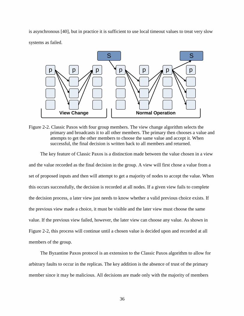
36
is asynchronous [40], but in practice it is sufficient to use local timeout values to treat very slow
systems as failed.
View Change
p p
S S
Normal Operation
p pp p p
Figure 2-2. Classic Paxos with four group members. The view change algorithm selects the primary and broadcasts it to all other members. The primary then chooses a value and attempts to get the other members to choose the same value and accept it. When successful, the final decision is written back to all members and returned.
The key feature of Classic Paxos is a distinction made between the value chosen in a view
and the value recorded as the final decision in the group. A view will first chose a value from a
set of proposed inputs and then will attempt to get a majority of nodes to accept the value. When
this occurs successfully, the decision is recorded at all nodes. If a given view fails to complete
the decision process, a later view just needs to know whether a valid previous choice exists. If
the previous view made a choice, it must be visible and the later view must choose the same
value. If the previous view failed, however, the later view can choose any value. As shown in
Figure 2-2, this process will continue until a chosen value is decided upon and recorded at all
members of the group.
The Byzantine Paxos protocol is an extension to the Classic Paxos algorithm to allow for
arbitrary faults to occur in the replicas. The key addition is the absence of trust of the primary
member since it may be malicious. All decisions are made only with the majority of members

37
being in agreement, so both the steps to choose a value and to accept it are completed at all nodes
rather than at only the primary, as in Classic Paxos. The result of this is that all nodes will record
the final decision and any of them could return the value to the external environment. An
example of Byzantine Paxos is shown in Figure 2-3 [71].
View Change
p p
S S
Normal Operation
p p p p p
Figure 2-3. Byzantine Paxos with four group members. The view change algorithm determines the primary without trusting the primary. The primary then chooses a value and attempts to get the other members to choose the same value and accept it. When successful, the final decision is written back to all members and returned.
The Chandra-Toueg algorithm is similar to the Classic Paxos algorithm in that it consists
of a series of asynchronous rounds in which a primary node attempts to direct a majority of other
members to decide on a value. It does not tolerate Byzantine failures. As before, if a round
appears to have failed, a new round is started with a new primary. One of the key differences in
this model is that the other members of the group initial provide the primary with their estimates
on what the decision should be, as well as the view number in which they last updated the value.
The primary awaits a majority of a given value and broadcasts it to all other members. It then
waits for the other members to ack or nack the value. If it receives a majority of acks, it will
record the final decision and broadcast it to all members. If it receives a single nack, however, it

38
initiates a new view and the selection of a new primary [50]. The diagram in Figure 2-4 depicts
the four basic steps of the Chandra-Toueg algorithm.
p
S
Normal Operation
pp pp
Round 1
Figure 2-4. Chandra-Toueg algorithm with four group members. All members send the primary a value/view pair. The primary makes the choice for the view and broadcasts to all members. It then awaits a majority of ack’s and records the decision if they are received. If a single nack is received, a new view is started with a new primary.
Related Work in Fault Tolerance
A wide variety of redundancy techniques have been proposed for providing fault tolerance
in the processor logic. As indicated previously, they can be generally categorized as being either
hardware-based or software-based, although as in the model considered in this dissertation, there
are inevitably some configurations that are a hybrid of the two. They may also be sub-
categorized by the level at which they provide the fault tolerance. For example, hardware-based
techniques have been proposed which replicate the entire processor core [2], [39], [47], [83],
[109], a simplified version of the processor core [5], [124], or only functional blocks within the
processor core [85], [89]. In software-based techniques, replication may be implemented at the
instruction set architecture (ISA) interface [16], [94], the operating system level [53], [116],
[121], the system call interface [15], [107], [115], or the application or compiler level [95]. These

39
options lead to trade-offs being made in terms of performance overhead, design complexity,
implementation cost, and fault tolerance transparency.
Hardware Fault Tolerance
There are many topics to consider within the realm of hardware-based fault tolerance
techniques. The focus of this dissertation in on improving the reliability of the processor logic,
and as such, the literature review is of previous work in that area. Of course, this form of fault
tolerance should not be applied in isolation. It is necessary to ensure the reliable operation of the
other components that comprise the computing platform, so a brief overview of previously
proposed techniques is also provided.
Processor Logic
One of the original hardware-based approaches for fault tolerance in processor logic is the
use of a small, simple watchdog processor to monitor the control flow and memory accesses of
the main processor and validate it in order to detect errors [80]. The greatest drawback to the
approach is that the watchdog processor must be provided with a Structural Reference Program,
which is output produced by the compiler that indicates the program structure while removing
the computational portions of the code.
More recent variations of this idea have been proposed to relax this requirement and to
permit the secondary processor to also assist in recovering from the errors. In [5] dynamic
verification is achieved by integrating a functional checker processor into the commit state of the
pipeline. All instructions completed in the main core are sent, along with the corresponding
operands and result, to the checker core to be verified before being committed. The checker core
can be simpler since it does not have to predict branch outcomes, decode instructions or resolve
operands.
40
Yet another approach that utilizes redundant hardware is the use of simultaneous
multithreaded (SMT) capabilities in processors such as the Intel®
More recently, chip multiprocessors (CMP) have allowed for similar multithreading across
processor cores with the added benefit that a hardware fault will not cause the same error to
occur in both copies of the thread [47]. The trade-off made is that the replication must be
coordinated across different cores, which results in greater latency and may stress the inter-
processor communications bandwidth. This is dealt with by allowing for a longer slack between
the main thread and its trailing replica, as well as pipelining the inter-processor communication.
Pentium 4 [99]. The
duplication of hardware blocks allows multiple, identical copies of a thread to be executed with
temporal redundancy and then checked against one another with a reasonable performance
overhead. The basic operation of the system is based on a duplicate thread that is created by the
hardware without the knowledge of the operating system. The second thread lags behind the
main thread while executing the same execution stream. It has a small impact on the processor
bandwidth since it has the benefit of all branch outcomes and data values being determined by
the main thread.
There are also designs in which the processor is explicitly replicated for the purpose of
improving reliability [55]. The outputs are monitored for differences and either forward error
recovery is achieved by ensuring fail-stop behavior at the detection of an error or backward error
recovery is provided by storing known good states and rolling back to them when an error
occurs. This form of processor replication has been implemented in the IBM G4 and G5 series
processors with support for backward error recovery [112]. The IBM processors are have
duplicate instruction fetch (I) and execution (E) units and a recovery (R) unit that is responsible

41
for validating the output of the E unit, as well as maintaining checkpoints of the processor state
in case a rollback and recovery is necessary.
The approach taken by HP in its NonStop systems is a forward error scheme in which all
processors act independently and without shared memory. They exchange messages over a
redundant bus interface and operate at a cycle-level lockstep while comparison circuitry validates
all outputs for consistency and special, self-checking logic is used to monitor for failures within
the cores. At the occurrence of a failure, the processor is designed to “fail fast” and remove itself
from the system until it can be replaced. These specialized systems are some of the most
advanced, and correspondingly, most expensive fault tolerant computing systems to be designed
[6], [9], [53].
Memory and I/O Devices
In designing a highly reliable computing platform, it is insufficient to focus all the effort
on improving the fault tolerance of the processing cores. It is also necessary to ensure the correct
functionality of the other hardware components in the system. Fortunately, this has proven easier
to accomplish and there are many proven and commonly applied techniques capable of providing
very high reliability at a reasonable cost.
One powerful technique that can be applied to main memory and storage devices is the
RAID parity described in above. In addition to this high-level, inter-device parity generation,
both main memory and storage devices also typically have lower-level, intra-device parity
generation ranging from single-bit parity to powerful Hamming ECC coding [23]. The
hierarchical application of parity has proven quite powerful and will likely continue to develop
into additional layers [61].
Another common type of protection often applied to computer peripherals are the various
forms of linear block codes. These include the simple parity and Hamming codes introduced

42
earlier, as well as cyclic redundancy codes (CRC) used in wired Ethernet, USB, Bluetooth, and
modems, as well as Reed-Solomon codes used in optical media such as CD’s and DVD’s. This
class of algorithms produces a checksum that is appended to the data on the media and provides
error detection and possibly correction capabilities.
The process of encoding using cyclic codes is done by multiplying (modulo-2) the data to
be protected by a generator polynomial. An n-bit CRC makes use of an n+1-bit generator
polynomial and is capable of detecting a single error burst of size n or less where a burst is
defined as the length of consecutive bits encompassing the error. It is also capable of detecting
some longer error bursts. To later decode and check for errors, the data are divided by the same
polynomial constant. If the result is a non-zero value, an error is known to have occurred. There
are numerous predefined generator polynomials for various applications with the most common
ranging in size from 9-bits (CRC-8) to 65-bits (CRC-64). There are also no limitations on the
size of the data on which the algorithm is applied as it is always possible to sign-extend the data
to the minimum length.
Reed-Solomon codes are similar but function on blocks of data rather than single bits and
are able to correct bursts of errors. The basic encoding process consists of representing blocks of
data by a polynomial and then sampling it at a greater number of points than the degree of the
polynomial used. For data represented by k symbols, each of which is m bits in size, a total of n
symbols are stored where n = 2m
There are also techniques for protecting the network interfaces of the system. One such
example is network adapter teaming, which involves teaming two or more physical network
– 1 and k < n. A maximum of (n-k)/2 faulty symbols can be
corrected.

43
adapters to function as a single adapter with a single IP address. This allows for load balancing
and transparent fail-over in case of a network card failure.
Software Fault Tolerance
There are a number of different layers at which software-based fault tolerance may be
implemented. The focus of this research is on the ISA interface, which is the lowest level of the
software stack. Previous research at this and other levels is briefly considered in this section.
Instruction Set Architecture
An example of fault tolerance implemented at the ISA level is the hypervisor-based
replication presented in [16]. As depicted in Figure 2-5, this work makes use of a hypervisor to
coordinate replicated execution across multiple physical systems that share a common hard disk.
The form of replication implemented is a hybrid of the passive and semi-active schemes. The
replicas all receive inputs from the external environment and actively execute the same sequence
of events. There is also the notion of a primary node that is designated a priori and is responsible
for removing nondeterminism from the system inputs. Only the primary node records the output
computed to the external environment.
Backup
SCSIDisk
Controller
PrimaryEthernetSCSI bus
Figure 2-5. Architecture of hypervisor-based duplex replication model.
The execution stream is partitioned into epochs defined by the instructions retired counter
by initiating an interrupt whenever the counter expires. The values for all nondeterministic
events that occur in the execution are decided on by the primary, which executes one epoch
44
ahead of the backup, and then distributed to the backup for injection at the same location in the
execution stream. This includes values read from the timestamp counter, DMA data, etc.
External interrupts are handled by buffering the vector and delaying their injection into all nodes
until the end of the epochs.
The failure of the primary node is detected by a timeout in a backup node, at which point
the backup node is promoted to being the primary and repeats any outstanding I/O requests that
cannot be verified to have been completed by the previous leader. The main differences of this
model to that considered in this dissertation are that a fail-stop fault model is assumed and only
simple fail-over to a single backup is supported. There is also the requirement in the prototype
developed for the work of an external coordinator since the hypervisor is not augmented with the
capabilities necessary to function independently. The fail-stop fault model limits the
effectiveness of the replication, and is especially limiting if the goal is to provide replication
across multiple cores within a package or motherboard to protect the system from single-event
upsets.
A number of other hypervisor-based replication architectures have been proposed. These
fall into two general categories, either semi-active virtual lockstep designs similar to the example
just given or fast checkpointing configurations in which the hypervisor sends snapshots of the
state of the guest system to one or more backups in a semi-passive fashion. The virtual lockstep-
based work is generally limited to a high-level design overview without specific details related to
implementation [25], [31], [78], [96], [97]. The fast checkpointing design is based on an
extension to the Xen hypervisor and addresses many of the hurdles of implementation [33].
Yet another vector for research has been in recording the deterministic execution of a guest
operating system with the application of the same techniques used in virtual lockstep, but not

45
replaying it in real-time. Instead, the recording is used to debug software, detect malware, or to
simply replay precise execution at a later time [37], [128], [129]. Any virtual lockstep
implementation should be portable to this use case, although it may be necessary to more finely
tune and possibly compress the log file associated with the recording. In virtual lockstep the log
only needs to cover the span between the primary and the slowest backup replica, whereas
deterministic log recording may require many minutes or even hours of logging time and result
in huge storage requirements.
Operating System
Although there have been successful implementations of fault-tolerant operating systems,
such as the Stratus Virtual Operating System (VOS) and the HP NonStop Kernel operating
system, the size and complexity of modern operating systems limits the widespread adoption of
such functionality in more common versions such as Windows®
There are challenges in maintaining application support when porting to a new operating
system, as well. Even though fault tolerant operating systems attempt to maintain POSIX
compliance and support ANSI-compliant versions of major programming languages, the
applications that can be ported are limited to those with source code available. The problem is
compounded by sparse device driver support and the learning curve associated with deploying
and learning a new operating system. These limitations constrain the use of specialized fault
tolerant operating systems to their current role in enterprise mainframes and make it unlikely that
commodity hardware will be supported.
or Linux. Both the Stratus and
HP implementations are tightly coupled to specialized, fault-tolerant hardware, which together
form a vertically-integrated platform targeted at mainframe-level enterprise applications [6], [9],
[53], [116], [125].
46
Middleware
Yet another option is to build a middleware layer that sits at the system call interface in the
operating system and provides replica coordination to the applications above it. An example of
this is presented in [15] where a Transparent Fault Tolerance (TFT) middleware is used to
coordinate application replication above the operating system level in much the same was as [16]
functioned at the ISA level. Execution is again partitioned into epochs and a deterministic state
machine model is maintained by ensuring that all replicas begin the in the same state and receive
the same sequence of deterministic inputs.
All systems calls made into the operating system, as well as all exceptions and interrupts
delivered to the applications, are intercepted by a designated leader node in the middleware. The
leader node again executes ahead of the followers and has the responsibility of removing all
nondeterminism from the system. In the case of nondeterministic systems calls, such as
gettimeofday(), the leader records the transformation of state resulting from the call and forwards
it to the other nodes in the replica group for injection at the same point in the execution.
Exceptions are buffered and are delivered to all nodes only at the end of the epochs when it is
known to be at a deterministic point in the execution.
This approach has many of the same drawbacks of the ISA model described above in that a
fail stop fault model is assumed and only simple failover can be performed. One additional
difficulty is a lack of predictable epoch boundaries since there is no guarantee that a system call
or exception will ever occur for certain workloads. To avoid this, the authors propose the use of
specialized binary object code editing to instrument the execution with guaranteed epoch
boundaries by decrementing a counter on each back branching instruction. Additional problems
arise when considering multithreaded processes and the use of shared memory for process
communication. Given the additional challenges and the limitation of implementations being

47
inherently OS-dependent, there is little perceived benefit of a system call approach over on at the
ISA-level.
Application/Compiler
The final approach considered for software-based integration of fault tolerance is that of
directly coding it into the applications. There are a numerous techniques for achieving this, but
most are based on modification to the compiler in an effort to relieve the programmer from
having to possess the specialized skills necessary to implement fault tolerance explicitly [88],
[95], [101]. In these compiler-based approaches, the instructions in the program are duplicated
and configured to use a different set of registers and physical memory than the original copy of
the program. The outputs from both copies of the program are compared at each store instruction
to ensure consistency.
Additional capabilities and optimizations are possible, including varying degrees of control
flow validation. For example, if the memory is protected by another mechanism, it is possible to
share the memory among the copies of the program. It is also possible in many cases to have the
compiler schedule the redundant execution during times at which the main program is stalled so
as to reduce the performance penalty. Control flow checking can be achieved by statically
computing a signature for each basic block of code and then verifying it at run-time. Most
approaches require some form of hardware support for the signature calculation, but there has
been work on supporting it completely in software, as well [87], [88].
Unfortunately, there are a number of drawbacks to this approach. The obvious limitations
are that it is limited to fault detection and is not applicable to any closed source applications.
There are also challenges in dealing with shared memory, exception handlers, and asynchronous
events such as interrupts, which require additional compiler capabilities and hardware-level
support to avoid loading different values in to each copy of the program.

48
Case Study: Stratus ftServer architecture
The Stratus®
They approach the problem by defining three fundamental components: lockstep
technology, failsafe software, and ActiveService
mid-range server systems are illustrative of many of the most advanced
hardware fault tolerance capabilities integrated into production computing platforms [116],
[117]. Unlike the top-of-the-line Continuum series and HP NonStop servers, the ftServer line
supports running commodity Windows and Linux operating systems and avoids the limitations
and cost of the completely vertical options. This is the use case that is the basis for the model
proposed in this dissertation.
TM
All other components are replicated as well, including the motherboards, memory, I/O
busses, and all peripherals such as network cards, storage devices, and remote management
infrastructure. The I/O subsystem is independent from the CPU and memory subsystem and the
interface is bridged using a custom chipset capable of detecting and isolating faults. One of the
goals of the design is to allow for the use of as many industry-standard components as possible
and only relying on a small amount of custom logic in each of the subsystems. The basic
architecture is depicted in Figure 2-6.
architecture. The lockstep technology is
implemented much like that of the HP NonStop system described above and consists of fully
replicated processors in either a TMR or a pair-and-spare configuration. In TMR, if one
processor fails, it can be taken offline and the system will run as a DMR until it is repaired. If
one processor fails in the pair-and-spare system, the pair will be brought offline and the backup
pair will be put into service.
The Stratus approach to failsafe software is to attempt to make the replication and all fault
tolerance functionality transparent to the operating system and user software. This permits the
use of a number of standard operating systems without modification. An effort was also made to

49
allow the operating systems to make use standard, software-supported fault tolerance
mechanisms such as the hard disk and memory RAID and network adapter teaming.
EmbeddedI/O
PCIDisksFault Detection
andIsolation
Fault Detectionand
Isolation
Processor
Chipset
Memory
EmbeddedI/O
PCIDisksFault Detection
andIsolation
Fault Detectionand
Isolation
Processor
Chipset
Memory
Mul
ti-pa
th I/
OLockstep
Figure 2-6. Stratus architecture with lockstepped processors and independent replicated I/O subsystem bridged with fault detection and isolation chipsets.
Finally, the ActiveServiceTM
Overall, the Stratus system encompasses a complete set of fault tolerance and automation
mechanisms and claim to support 99.999% uptime in production systems. The greatest
drawbacks to their systems are the relatively high cost resulting from the use of customized
chipset hardware and the limited range of applicability. It is not possible to integrate the fault
tolerance mechanisms into existing hardware, and the platforms that are supported are limited.
The goal of the model presented in this research is to achieve many of the same goals of the
Stratus system while avoiding expensive and limiting hardware support.
architecture consists of platform monitoring and remote
support capabilities integrated throughout the platform. The goal is to automate the monitoring
and repair of the system to the greatest degree possible, as well as to allow for remote
troubleshooting and resolution if intervention is necessary.
Fault Injection
In most cases, the best method of assessing the benefits of a fault tolerant solution is to test
it since even moderately complex designs are extremely difficult to model analytically. Fault

50
injection provides a means of gathering empirical data related to the behavior of the system after
the introduction of a fault. By introducing the faults in a controlled manner, it is possible to
ascertain how they propagate through the system and to determine when and how they emerge as
a system failure.
There are multiple levels at which to model the faults. They can be modeled at the
transistor or wire level through RTL injection, but this is an expensive and slow process that
requires having the full specification of the chip available [3]. The benefit to the approach is that
it is possible to directly associate an event such as a particle strike to the corresponding behavior
in the device. Of course, it is not possible to do until the design is finalized and detailed analysis
is done regarding the properties of the process technology used to fabricate the device
Alternatively, it is possible to model the faults at the register level, which requires only the
microarchitecture specification, either in the form of a software emulation model or a real
physical device [48], [65], [73], [91]. This method is less accurate in modeling the underlying
effects actually introducing the faults, but it provides much of the same information and can be
done much faster and easier. This is done by introducing a bit flip or a stuck bit into the actual
register and letting it continue execution. In both approaches, it is necessary to conduct a number
of trials to determine the behavior under different circumstances. With enough data, it is possible
to determine the probability of a fault affecting the correct outcome of the software. One
mechanism of stating this probability of incorrect behavior is the architecturally correct
execution (ACE) analysis, as described in [123].
The approach taken in this research is the latter and is most similar to [73] as it makes use
of a hypervisor to model faults at the register level by injecting them into the physical processor.
Previous work in the area of fault injection often focuses on a subset of the processor registers
51
and usually limits experimentation to a few of the most critical ones in the architecture [3], [48],
[73], [122], [123]. As will be shown in Chapter 6, one of the main goals of this research is to
look at all meaningful registers in the processor.
Many-Core Architectures
Many-core is the progression of the chip-level multi-processing architecture to the point of
having dozens or even hundreds of cores on a single silicon die. It is a significant change in the
design of processors, which have historically scaled almost solely based on increases in the clock
frequency. As modern designs approach fundamental barriers to frequency scaling, combined
with an increasing disparity in the speed of the processor and the latency of main memory,
computer architectures are increasingly relying on thread- and appliciation-level parallelism to
offer improvements in performance.
Network-on-Chip Architectures
One of the key architectural changes needed to support a large number of cores on a single
silicon substrate is the transition to a form of distributed system. It is not practical to have a fully
synchronous system as clock skew cannot be kept within an acceptable range. Instead, an array
of locally synchronous devices is necessary which can be treated globally as an asynchronous
system.
Such a configuration necessitates a point-to-point communication protocol. Shared
communication mediums, such as arbitrated busses or ring buffers, do not scale to deliver the
necessary performance levels, so packet-switched micro-networks have been developed [10],
[12]. These networks-on-chip (NoC) are logically similar to networks used at the macro level
with a router integrated into each core and data routed over multiple hops from each source to
destination.
52
The type of routing used varies based on trade-offs such as predictability vs. average
performance, router complexity, and general network robustness. In order to achieve fault
tolerance, a form of adaptive routing is desirable over static paths and wormhole routing (a form
of cut-through switching) is typically used to achieve higher bandwidth and lower latency than
circuit or packet switching techniques at the cost of slightly higher energy usage when the
network traffic is high [10], [29]. It works by breaking the packet into smaller units called flits
with the necessary routing information provided in a short header portion of the initial flit. This
allows the router to determine the next hop very quickly and begin forwarding parts of the packet
before the entire packet even arrives at the node.
Another challenge in supporting a large core count on a single chip is supplying all of the
processor cores with adequate bandwidth to main memory. One likely solution is the use of a
three-dimensional stacked design in which the main memory is attached directly to the processor
die and packaged in the same substrate [118]. There are a number of processes for stacking,
which can be roughly categorized as face-to-face or face-to-back processes. In face-to-face, the
tops of both chips are fused together and deep vias are used to connect the chip to the package. In
face-to-back, the top of the first chip is fused to the back of the second chip and vias are formed
to connect them. The wafers must go through a series of extra processing steps including
thinning of the wafer to remove extra silicon from the back, alignment to line up the chips with
the necessary submicron tolerances, planarization and polishing to atomically smooth
dimensions, bonding to fuse together the copper connections, and finally any additional steps
required for via formation and packaging. The final result is an array of processor cores with
very short, high-bandwidth access to main memory.
53
There are a number of methods for achieving fault tolerance within a NoC system. Both
the origin-based routing algorithm and the interstitial redundancy mechanisms described earlier
can be used to compensate for physical node or link failures within the network. Soft errors
resulting from single event upsets and crosstalk pose an issue, as well [43]. They can be handled
through the use of error correction coding to provide forward error correction capabilities and
retransmission when the error is not correctable. The most important piece of data to protect is
the header flit with the routing information because corruption in those bits can result in delivery
of the data to the incorrect node, at which point the entire packet must be retransmitted even if it
is otherwise correct. One common retransmission technique is to supply a three-flit
retransmission buffer for each node. This allows for the three cycles necessary for the
transmission to the next node, the error checking, and the return of the negative
acknowledgement [90].
The Polaris processor is a prototype NoC-based architecture developed as a proof-of-
concept by Intel® Corporation [119]. It consists of 80 4GHz processing cores in a 10x8 two-
dimensional mesh grid. Each processor has a routing interface block (RIB) to encapsulate the
data being transferred and is connected to a 5-port wormhole-switched router that forwards the
packets to the four neighboring cores and to the stacked main memory. The design allows any
core to communicate directly with any other core in the chip over a virtual channel with a
bandwidth of 80GB/s. Each of the cores in the Polaris system is relatively simple and designed
specifically to achieve the goal of a teraflop level of performance in a single chip with less than
100W of power dissipation. The cores will be expanded in the future to provide a mixture of
general purpose, as well as specialized computing capabilities, including graphics processing,
floating point, and encryption.
54
Parallel Programming
The greatest challenge in the continued advancement of overall performance in many-core
architectures is finding ways to take advantage of all the computing resources available. It has
been shown that obtaining a noticeable benefit from more than even two cores in typical,
interactive desktop applications is difficult given the limited amount of parallelism available
[41]. Amdahl’s Law states that the speedup achievable when running on N processors is limited
by the ratio of parallel tasks, P, versus those that must be done serially, S.
N
PSPSNSpeedup
+
+=)( (5)
Some proposed methods of increasing the amount of thread-level parallelism are
speculative prefetching and procedure execution, data dependence speculation, data value
prediction, and run-ahead execution using “helper” cores. These techniques are limited in the
speed-up achieved and offer less than a 40% improvement on average for the SPEC CPU2000
benchmarks [66], [77]. Without a significant breakthrough in coding and compiler technology,
programmers will be unlikely to make full use of the large number of cores available in most
common, interactive applications [41].
Virtualization and Logical Partitioning
This section introduces system virtualization and logical partitioning, which are two of the
technologies considered in the fault tolerant architecture to be presented in Chapter 3. The
specific types of virtualization considered are based on hardware virtual machines, while the
form of logical partitioning considered is based on static, BIOS-enabled partitioning. A brief
description of each is provided with the focus being on the aspects most relevant to the
replication model to be introduced in the next chapter.

55
Hardware Virtual Machines
Hardware virtualization refers to the decoupling of the operating system from the physical
hardware of the computer system, which is different than that of software or application virtual
machines (e.g., Java) that are used to make an application portable across instruction set
architectures. In hardware virtualization, the operating system is presented with a virtual
representation of the hardware that does not necessarily have to have a one-to-one mapping to
the physical resources backing it. Such an abstraction provides a number of benefits including
resource sharing, device and feature emulation, inter-platform software portability, and others.
One feature that is very beneficial to replication is the simplification of the interface between
hardware and software.
The implementations of hardware virtual machines are often subcategorized as being type-
I or type-II. Type-I virtual machines are also known as bare-metal hypervisors because they are
installed directly on top of the hardware and must have full support for drivers, scheduling,
resource sharing, etc. Examples of a type-I monitors include IBM® z/VM, Xen, VMware® ESX
Server, and Microsoft® Hyper-V. Type-II virtual machines, on the other hand, are known as
hosted hypervisors because they are installed within a host operating system and make use of the
host’s system calls to interact with the hardware. They also have the benefit of being able to use
the host’s driver base, as well as its existing scheduling and resource sharing capabilities.
Examples of type-II implementations include KVM, VMware® Workstation, and SWsoft®
Although virtualization technologies have been in use in much the same form for over four
decades, there has been a significant amount of work recently in improving the functionality,
performance, and ease of hypervisor design, as well as expanding the usage models supported.
The development of hardware and microcode extensions in processors and chipsets has
Parallels Desktop.
56
eliminated many of the complications prevalent in virtualizing the Intel®
One of the key features provided by the Intel virtualization hardware extensions is a new
mode of operation, which is referred to as VM root mode. This mode is enabled before a guest
operating system is booted. The new guest is then resumed in VM non-root mode where it has
access to all four ring levels. It is also guaranteed to exit to the hypervisor on all privileged
instructions, and the processor will change the linear address space on each control transfer.
When the hypervisor needs to gain control, it does a VM-exit back to VM root mode. This new
mode allows the hypervisor to cleanly and efficiently host legacy operating systems.
x86 architecture. This
included such things as ring aliasing, address-space compression, and non-faulting access to
privileged processor state [57].
A portion of the host and guest state is maintained in a reserved page of memory called the
Virtual Machine Control Structure (VMCS), which is set up with a physical address mapping
known to the hypervisor and passed to the processor using a VMPTRLD instruction whenever a
guest is launched for the first time on the processor. This structure stores the control, segment,
instruction pointer, stack, and flag registers, as well as a number of control fields to define the
types of operations that cause VM-exits. Some of the fields in the VMCS are set by the
hardware, such as the one indicating the version of VMCS format. Most of the values are set by
the hypervisor with the VMWRITE instruction. Once all fields have been appropriately
programmed by the hypervisor, the guest is set to be executed on the processor with either a
VMLAUNCH instruction if it is the first time being executed on that core or a VMRESUME
instruction if it has already been executing there. When a guest VM exits back to the hypervisor,
the fields in the VMCS have been appropriately updated by the hardware and are read by the
hypervisor with a VMREAD instruction. There is some necessary guest state that is not present

57
in the VMCS that the hypervisor must save and restore manually on each guest transition. The
fact that this structure stores key state of the guest’s virtual processor makes it useful for
detecting divergences in virtually lockstepped systems, and will be discussed in Chapter 6.
Practically all modern computing platforms provide a similar form of hardware-based
virtualization support and future systems will have support integrated throughout the entire
platform, including virtualization aware peripherals. Those that do not can still take advantage of
paravirtualization approaches in which the guest operating system is made aware it is being
virtualized or the finely-tuned dynamic binary translations developed to avert the portions of
code that are troublesome to virtualize [1], [74].
As indicated in the introduction, these advancements have significantly decreased the
performance overhead of virtualization, which now approaches that of native hardware.
Benchmarks run on VMware®
Logical Partitioning
ESX Server, for example, show a virtualized guest running at an
average of 97% of native for the SPEC CPU2000 Integer suite, 94% to 97% of native for
Netperf, and 91% of native for SPECjbb2005 [120]. Additionally, research has been done on
techniques for applying virtualization to systems dynamically. This self-virtualization transitions
the operating system from running on bare hardware to running under the control of a hypervisor
without disturbing the applications running in it and allows for truly native performance when
the guest is not being virtualized [25].
In order to replicate the execution of a guest operating system within a single physical
platform, it is beneficial to be able to partition the system in such a way that multiple hypervisors
can be executed concurrently. This avoids the introduction of a new single point of failure by
allowing for the hypervisor itself to be replicated, in addition to the guest operating system. The
partitioning and can be done through logical partitioning.

58
Logical partitioning of a system involves restricting the physical resources seen by an
operating system or hypervisor. The goal of the logical partitioning of the system is much more
basic than that of a typical hypervisor. It is used to carve up system resources at boot time such
that multiple guests can be restricted to independent portions of the underlying hardware. Once
this task is completed, it attempts to get out of the way and allow the operating system or
hypervisor in the partition to run unobstructed. It requires little or no interaction with the guests
after initialization and is typically done through the platform firmware with a minimal amount of
logic.
Power On
EFI Shell
Copy EFI Shell
Boot Partition 0
Disable Config Writes
Boot Partition 1
Figure 2-7. Sample control flow for an EFI BIOS being logically partitioned at boot time.
An example of logical partitioning is given in Figure 2-7, where an EFI-compliant BIOS
alters the ACPI and ICH data reported to mask some of the available processors, memory
regions, timers, and I/O devices, which can be allocated to other guests. The EFI shell spawns a
copy of itself to manage booting the second partition after the first has indicated a successful
boot sequence. The challenges in logical partitioning include loading a guest OS at an alternate
base address, allowing cooperative scanning of shared busses such as PCI, and allowing
independent guest reboot.
Similar, but more advanced partitioning support is provided in high-end IBM severs and
mainframes where the allocations can be made at a fine granularity and adjusted dynamically at
run-time [4], [56]. The use of logical partitioning has historically been limited to mainframe

59
systems, but as with many other such technologies, it will move into personal computers as it
becomes more practical and useful. That is when the personal computers have a large number of
cores within a single socket or motherboard.
Physical Hardware
HypervisorOS 1 on
Physical Hardware
OS 3 onVirtual
Hardware
OS 2 onVirtual
Hardware
CPU 1
MEM 1 MEM 2
CPU 4CPU 2 CPU 3
MEM 3 MEM 4I/O 1 I/O 2
VCPU 1
VMEM 1
VCPU 2
VMEM 2I/O I/O
Partition 1 Partition 2
Figure 2-8. Partitioned quad-core platform with one partition hosting an OS directly and the other partition hosting a type-I hypervisor that has two guest operating systems.
Figure 2-8 represents how a quad-core platform might be simultaneously partitioned and
virtualized. The first partition in the diagram is hosting a standard operating system directly,
whereas the second partition is executing a type-I hypervisor that is running two guests. The
partitions are not required to be symmetric but must be onto mapped to physical resources. The
virtual machines, however, can virtualize hardware that does not map directly to that physically
provided by the machine.
The objectives of this chapter are to provide a brief background on the key technologies
discussed in the subsequent chapters, as well as to give a broad view of the general direction the
computing industry is going in terms of platform architecture and reliability while calling out the

60
trends that support the model to be developed and analyzed in this dissertation. Relevant prior
research is also summarized to provide a basis for existing mechanism and to allow comparisons
to be made to the proposed methodologies.

61
CHAPTER 3 PROPOSED FAULT TOLERANT ARCHITECTURE
Architecture Overview
The goal of the generalized system model presented in this chapter is to provide dynamic
fault tolerance capabilities to the processing nodes of a many-core platform without expensive
changes to the underlying hardware or operating system. This is achieved through replicated
execution across virtually lockstepped processor cores where the coordination and fault detection
logic are incorporated into the software-based hypervisor layer [62], [63].
This section describes the key aspects of the platform partitioning and virtualization,
replica communication and coordination, and platform monitoring as they apply to fault tolerant
virtual lockstep model. An effort is made to allow for flexibility in the degree of fault tolerance
provided and in the type of hypervisor required by considering the replication and
communication protocols in a generic fashion. The hypervisor is also brought into the sphere of
replication to avoid the introduction of a new single point of failure.
Replication Model Scope
As mentioned in Chapter 1, the target platforms for the proposed model are low- and mid-
range servers that may have multiple processor sockets and a large number of total processor
cores. These classes of servers are not well suited to being fully replicated for reasons of cost and
complexity. Instead, they are better served by allocating a small percentage of the total number
of cores for replicated execution. This adds little additional overhead and allows for replicated
execution only when the reliability of a core is questionable or when reliable operation is most
critical. Such a model also allows for an adaptable trade-off to be made between performance
and fault tolerance since the cores can still be used for normal execution when replicated
execution is not necessary.

62
In the semi-active replication model presented, the focus is on protecting the processor
cores themselves, which typically have no protection beyond parity bits on key registers. The
goal of the replication is to detect faulty operations and recover from them before erroneous data
leave the processor. The hard disk, network interface devices, and similar peripheral I/O devices
are not included in the sphere of replication. There are numerous techniques already commonly
available for providing fault protection for these devices, several of which were mentioned
briefly in Chapter 2 [59]. The main memory is also not explicitly protected, as it too can be
easily protected with existing means. Unlike the other components of the platform, however,
there is a degree of inherent protection provided by the replication since each replica maintains a
complete memory image of the guest.
A simplification in the model is made by considering only uniprocessor virtual machine
guests. This is done because it is significantly more complex to maintain the deterministic state
machine model when considering multi-processor guests, as it is necessary for all replicas to
agree on the ordering of the mutex acquisitions. Many of the techniques necessary for achieving
such coordination have been developed in other work, but the resultant impact to performance is
still too high [7], [38], [54], [64], [115]. Once refined, these techniques could be applied as a
direct extension to the model presented in this dissertation.
Platform Partitioning and Virtualization
The system configuration consists of a hypervisor layer on top of a partitioned, many-core
platform. The exact number of cores is not critical, but it is assumed that systems will generally
have dozens or even hundreds of cores so that the overhead of using a small number of entire
cores for replication is reasonable. There may also be multiple sockets either distributed on the
same motherboard or across separate physical systems connected by a high-speed, low-latency
interconnect.

63
At least one processor core and a portion of main memory must be available in a separate
partition for use in hosting a replica. Depending on the degree of replication implemented,
multiple replica partitions may be necessary. The platform partitioning is done either logically or
physically, although logical partitioning is preferred since it allows for replication within a
single, physical system.
The hypervisor code is modified to provide the capabilities necessary for replicating
execution, and the guest virtual machine replication is initiated either statically when the guest is
launched or dynamically based on input from platform-level monitors that indicate the possibility
of an imminent uncorrectable error. A single instance of the hypervisor is executed in the main
partition, as well as one in each of the replica partitions. Of course, these copies of the hypervisor
are aware of one another and know how to communicate and coordinate the execution of the
guests.
CPU 1
MEM 1
CPU 2
MEM 2
CPU 3
MEM 3
CPU 4
MEM 4
CPU M
MEM M
Main VMM Replica VMM
OS 1 OS 2 OS 3 OS 4 OS *
Main Partition
CPU N
MEM N
ReplicaPartition
Figure 3-1. Logically partitioned many-core platform with each partition hosting a hypervisor.
The main partition hosts one or more guest virtual machines while the replica partition hosts a virtually-lockstepped replica of a single virtual machine.
An example of the general design is shown if Figure 3-1, which depicts a many-core
platform that is logically partitioned into two heterogeneous containers. The hypervisor in the
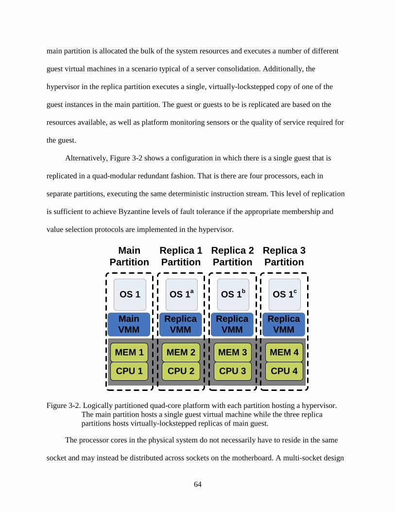
64
main partition is allocated the bulk of the system resources and executes a number of different
guest virtual machines in a scenario typical of a server consolidation. Additionally, the
hypervisor in the replica partition executes a single, virtually-lockstepped copy of one of the
guest instances in the main partition. The guest or guests to be is replicated are based on the
resources available, as well as platform monitoring sensors or the quality of service required for
the guest.
Alternatively, Figure 3-2 shows a configuration in which there is a single guest that is
replicated in a quad-modular redundant fashion. That is there are four processors, each in
separate partitions, executing the same deterministic instruction stream. This level of replication
is sufficient to achieve Byzantine levels of fault tolerance if the appropriate membership and
value selection protocols are implemented in the hypervisor.
Replica VMM
OS 1c
CPU 4
MEM 4
Replica 3Partition
Replica VMM
OS 1b
CPU 3
MEM 3
Replica 2Partition
Replica VMM
OS 1a
CPU 2
MEM 2
Replica 1Partition
Main VMM
OS 1
CPU 1
MEM 1
MainPartition
Figure 3-2. Logically partitioned quad-core platform with each partition hosting a hypervisor. The main partition hosts a single guest virtual machine while the three replica partitions hosts virtually-lockstepped replicas of main guest.
The processor cores in the physical system do not necessarily have to reside in the same
socket and may instead be distributed across sockets on the motherboard. A multi-socket design
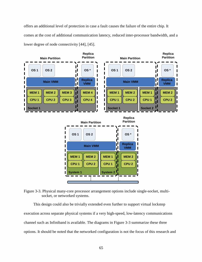
65
offers an additional level of protection in case a fault causes the failure of the entire chip. It
comes at the cost of additional communication latency, reduced inter-processor bandwidth, and a
lower degree of node connectivity [44], [45].
Socket 2Socket 1
CPU 1
MEM 1
CPU 2
MEM 2
Main VMM ReplicaVMM
OS 1 OS 2 OS *
Main Partition
CPU 4
MEM 4
ReplicaPartition
CPU 3
MEM 3
Socket 1
CPU 1
MEM 1
CPU 2
MEM 2
Main VMM ReplicaVMM
OS 1 OS 2 OS *
Main Partition
CPU 2
MEM 2
ReplicaPartition
CPU 1
MEM 1
System 2System 1
CPU 1
MEM 1
CPU 2
MEM 2
Main VMM ReplicaVMM
OS 1 OS 2 OS *
Main Partition
CPU 2
MEM 2
ReplicaPartition
CPU 1
MEM 1
Figure 3-3. Physical many-core processor arrangement options include single-socket, multi-socket, or networked systems.
This design could also be trivially extended even further to support virtual lockstep
execution across separate physical systems if a very high-speed, low-latency communications
channel such as Infiniband is available. The diagrams in Figure 3-3 summarize these three
options. It should be noted that the networked configuration is not the focus of this research and

66
all optimizations are meant to improve the performance of single-socket many-core, and possibly
multi-socket platforms, but the communication protocols considered do not fundamentally
inhibit the networked machine configuration.
Platform Monitoring
Platform level monitoring consists of fault detection and other sensor circuitry embedded
throughout the platform, which varies by system. Examples of this include parity bits in the
cache and memory regions, as well as within some processor logic structures. It also includes
temperature monitors in the processor, motherboard, memory devices, and chassis. More
advanced approaches are also possible, such as the use of processor built-in self-testing (BIST)
logic to check for failures and wear-out throughout the processor [108]. Most server platforms
consolidate the monitoring facilities using a baseboard management controller (BMC)
microcontroller and expose them through the Intelligent Platform Monitoring Interface (IPMI).
The specific forms of platform monitoring supported and the triggers used to determine when to
initiate replicated execution must be considered on an individual basis and integrated
appropriately.
Fault Model and Fault Tolerance Overview
This section describes the fault model considered, as well as the fault tolerance capabilities
provided by the replicated virtual lockstep execution. The limitations of the fault detection
mechanisms are also discussed.
Fault Models
The fault models typically considered in computing platforms can be roughly categorized
into two general types. The first is the fail-stop fault model, in which an operating system is
expected to execute correctly until an uncorrectable error leads to a failure. At that point, the
system will stop functioning and the failure will be immediately apparent. The second case is the

67
Byzantine fault model, where the operating system may fail in an arbitrary fashion that is not
necessarily detectable. Not only that, but it may also be malicious and purposely attempt to
deliver incorrect results.
Neither of the fault models is completely accurate in describing the behavior of most real-
world systems. Because of this, an intermediate model is considered in this dissertation. A fault
is assumed to not immediately cause a system failure or to even be detectable. It is also presumed
that there is not a blatant malicious attack being conducted at the hardware level in order to
circumvent the fault detection logic. In fact, in real systems, this is almost always the case. For
example, a single faulty bit in a random register of an Intel®
Even behavior officially designated to be undefined by Intel will almost always follow a
valid sequence of events and fail with an undefined opcode (UD#) exception, a general
protection (GP#) exception, or possibly cause a machine check exception (MCE). In fact, the
system may never crash, as the fault may be masked in such a way that it becomes benign, or it
may corrupt the processor state in such a way that the error goes undetected and lies dormant
until a later time. The second case is silent data corruption and is the most concerning since it
results in incorrect results being produced without any indication they are erroneous.
processor is unlikely to cause an
immediate system crash on the subsequent instruction, but it is also unlikely that the processor
will behave in a completely random or malicious fashion.
Faults are considered at the granularity of bits in registers of the processor. This is in
contrast to gate-level faults, such as those modeled using register transfer language (RTL)
specifications for processors. For the purposes of this dissertation, the main source of the faults is
considered to be transient bit flips resulting from single-event upset events in the logic. However,
the model does also protect against multi-bit events, as well as intermittent and wear-out faults
68
that cause incorrect values to be recorded in the registers. Some indirect protection is provided
against faulty bits in memory or cache structures for values that are eventually propagated to the
processor registers and result in the generation of faulty output.
Fault Tolerance Capabilities
The fault tolerance capabilities considered in this model are all based on the replication of
system execution across disparate processor cores and vary from simple error detection via
duplex configurations to arbitrary error detection and correction with Byzantine-capable
configurations. Again, the sphere of replication extends fully only to the processor cores
themselves, as well as any uncore features (i.e., not computing engines) that may be present
within the processor die.
In general, the detection of errors in replicated systems is achieved by comparing the pin-
level outputs generated by the processor cores and monitoring for inconsistencies. This method
of fault detection is supported in the proposed virtual lockstep model. An example is given in
Figure 3-4 where the accesses to the output value buffer are depicted for a duplex system
consisting of a primary and a single backup. The primary inserts values written to I/O ports and
through memory mapped I/O into the buffer. Then, then the backup reaches the same point in the
execution, it retrieves the values and compares them to those that it has generated. If true
determinism is maintained, the values should be the same. If they are not, a divergence is
detected.
Unfortunately, it is not possible to know exactly when the fault occurred. For example, if a
particle strike causes a bit to flip in a processor register, a number of instructions are likely to be
executed before the value in the register is read. Alternatively, the faulty value may not be
immediately read at all and instead be written back to memory and not accessed until much later
and via a different register. It is only when the value from the register is used, and the result is

69
seen as output from the processor, that the error will be manifested in a detectable form. That is,
as depicted in the figure, the fault may be injected some time before the first output divergence.
In the example given, there are two OUT instructions which still match, as well as an MMIO
operation. It is not until the third OUT instruction that the fault has propagated to the value being
written, at which point it becomes detectable.
... I/OValue
Fault Injected
Primary
Backup
Output BufferSlot 1
Output BufferSlot n
Output BufferSlot 1
Delay
I/OValue
I/OValue
I/OValue
I/OValue
MMIOValue
ValueMismatch
I/OValue
I/OValue
I/OValue
I/OValue
I/OValue
MMIOValue
MMIOValue
MMIOValue
MMIOValue
I/OValue
Figure 3-4. Fault detection inherent in virtual lockstep output value buffer. Divergence is
detected when backup generates value that differs from the current head of the buffer.
An obvious limitation of the basic duplex output value comparisons are that even when an
error is detected, it is not possible to know which replica is correct and what the true value
should be. In order to support fault correction, the next level of fault tolerance complexity is
necessary. It involves triplex configurations and the trivial combinations, such as the pair-and-
spare scheme introduced in Chapter 2. This is supported by simply having more backup replicas
and designating a node or a piece of logic as a voter. The voter is responsible for determining the
value based on the majority of the replicas and appropriately directing the hypervisors to shut
down faulty guest and reintegrate fresh replicas.
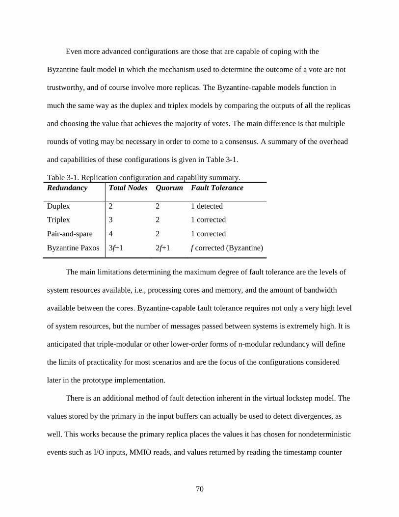
70
Even more advanced configurations are those that are capable of coping with the
Byzantine fault model in which the mechanism used to determine the outcome of a vote are not
trustworthy, and of course involve more replicas. The Byzantine-capable models function in
much the same way as the duplex and triplex models by comparing the outputs of all the replicas
and choosing the value that achieves the majority of votes. The main difference is that multiple
rounds of voting may be necessary in order to come to a consensus. A summary of the overhead
and capabilities of these configurations is given in Table 3-1.
Table 3-1. Replication configuration and capability summary. Redundancy Total Nodes Quorum Fault Tolerance
Duplex 2 2 1 detected
Triplex 3 2 1 corrected
Pair-and-spare 4 2 1 corrected
Byzantine Paxos 3f+1 2f+1 f corrected (Byzantine)
The main limitations determining the maximum degree of fault tolerance are the levels of
system resources available, i.e., processing cores and memory, and the amount of bandwidth
available between the cores. Byzantine-capable fault tolerance requires not only a very high level
of system resources, but the number of messages passed between systems is extremely high. It is
anticipated that triple-modular or other lower-order forms of n-modular redundancy will define
the limits of practicality for most scenarios and are the focus of the configurations considered
later in the prototype implementation.
There is an additional method of fault detection inherent in the virtual lockstep model. The
values stored by the primary in the input buffers can actually be used to detect divergences, as
well. This works because the primary replica places the values it has chosen for nondeterministic
events such as I/O inputs, MMIO reads, and values returned by reading the timestamp counter

71
with RDTSC. The backup replicas do not have a way of verifying these values, and in fact, it is
expected that the values differ from those that the backup generates since that is the point of
using the buffer.
I/O... I/O I/O I/O I/OMMIOMMIOMMIOI/O RDTSCRDTSC
I/O I/O I/O I/OMMIOMMIO RDTSCI/O
Fault Injected
Primary
Backup
Input BufferSlot 1
Input BufferSlot n
Input BufferSlot 1
Delay
Input TypeMismatch
Figure 3-5. Fault detection inherent in virtual lockstep input value buffer. Divergence is detected
when backup requests input value for a different operation than is at the current head of the buffer.
What the backup can verify is the ordering of the types of operations. An example is given
in Figure 3-5 where the injection of a fault eventually propagates through the system and causes
the backup replica to reach an I/O-based IN instruction that the primary did not have. Instead, the
primary reached a memory-mapped I/O read and stored those results in the buffer. At this point,
it is known that the backup execution has diverged. It should be noted that the fault may have
caused the backup to receive different values than it otherwise would for the operations prior to
this detection point, but these go undetected as long as the type of operation matches since these
input values are always overwritten. There is a minor optimization possible in some cases, for
which scrutinizing the value is beneficial even if the types match. For example, if the access
types are both I/O IN operations, but the ports being read from do not match, that is also enough
information to indicate a divergence.

72
The detection of errors at the processor I/O inputs and outputs is not ideal; however,
especially if the goal is to determine the source of the error or to avoid checkpointing system
states that include the fault. One method of catching the problem earlier is to compare the
internal state of the processors at regular intervals [110]. This technique is covered in more detail
in Chapter 6.
Virtual Lockstep Overview
Virtual lockstep involves replicating the execution of complete guest operating systems
under the control of a hypervisor. This section describes the basic requirements necessary to
achieve such replication. These general principles form the basis for the prototype developed in
Chapter 4.
Deterministic Execution
In order to run replicas in virtual lockstep, it is necessary to implement a form of
deterministic state machine by removing all nondeterminism from the execution of the guest
virtual machine [104]. This includes synchronous sources such as instructions that access the
timestamp counter or read in data from an I/O port, as well as asynchronous sources, such as
external interrupts. Direct memory access (DMA) replication must be dealt with as a
combination of both cases (i.e., a nondeterministic I/O operation that occurs asynchronously).
The replicas must be synchronized by the hypervisor based on deterministic points in the
execution. There are natural points in most execution that can be used. For example, an access to
a control register or a write to an I/O port will occur at the same point in the execution if
everything up to that point is also deterministic. The problem is that some guests may not have
any such synchronization points, or may not have a high enough frequency. A common
mechanism for achieving an acceptably high rate of such deterministic points is to program

73
counters in the processor to expire at regular intervals based on the retirement of certain types of
instructions.
The novel mechanism used in the virtual lockstep prototype developed is to use VM exits
from VM non-root mode to VM-root mode as the synchronization points. That is, each time a
VM exit occurs that transfers control back to the hypervisor at a point in the execution that is
guaranteed to be deterministic, a counter is incremented and the hypervisor is given the
opportunity to inject asynchronous events, such as virtual interrupts into the guest. This ensures
that the asynchronous events occur deterministically in all replicas. This mechanism does imply
that a steady stream of deterministic VM exits must be ensured. The details on how this is dealt
with are deferred to the design specifications in the next chapter.
Data from the synchronous, non-deterministic instructions, which include those that do
string or value I/O operations, memory-mapped I/O, or read the hardware timestamp counter,
must be copied from the primary replica to the one or more backup replicas. This is achieved
with a buffer that is shared among all hypervisors in a typical producer/consumer fashion. The
primary signals the backup(s) when an item is available, and when a backup gets to the same
synchronous instruction, it retrieves the data stored in the buffer and verifies it matches the type
of operation it expects. It then either uses the input it received or verifies the output it produced,
depending on the direction of the event.
For basic n-modular redundancy, the buffer is placed in a central location that is accessible
by all replicas and may be accessed over a network connection. In Byzantine-capable
redundancy configurations, each replica maintains a local buffer that is kept up to date using a
distributed consensus protocol.

74
The asynchronous, nondeterministic events (i.e., external interrupts) are captured by the
primary and placed into a second shared buffer. Their delivery into the primary is delayed until
the first instruction following a deterministic point in the execution for which the guest is ready
to accept the interrupt. If both of the requirements are met, the event is injected and its details are
recorded in the shared buffer. The backup replicas peek at this buffer to determine the point at
which they must inject the next event, which is defined by the deterministic event count. When a
replica arrives at the target position, the interrupt event is removed from the shared buffer and
injected. It is assured that the event will be deliverable, unless a fault has occurred, since the state
of the system is, by definition, identical to the primary.
Platform Partitioning Requirements
If the system is to be physically partitioned across two or more complete systems, it is
necessary to have a high-speed, low-latency communication protocol for transferring data
between the replicas. This can be a high-speed network, Infiniband, fibre channel, or similar
technology. If the interface is too slow or has a high latency, it can have a severe negative impact
on the performance of the guest.
Alternatively, a logically partitioned platform is well suited with a shared memory form of
inter-process communication. These differences can be reconciled such that a single
implementation can be either physically or logically partitioned by implementing the
communication protocol used by the hypervisors with a socket interface. The socket addressing
scheme can be easily change from local pathnames (AF_UNIX) to Internet addresses
(AF_INET).
One form of logical partitioning is based on using firmware to partition the system
resources at boot time. Specifically, a modified Extensible Firmware Interface (EFI)-capable
BIOS is used to boot two or more operating systems, or in this case, hypervisors on the same

75
physical system. Each of the hypervisors is booted with its own view of the system, which
consists of an exclusive portion of the total processor, memory, and I/O resources, as well as
support logic to deal with the sharing of certain features that must be common across partitions,
such as timers and the PCI bus. The boot flow of a modified EFI BIOS was given previously in
Figure 2-7.
There are certain requirements that must be met by the guests of the logical partitions to
function correctly while sharing the physical resources. The memory resources can be split up
through the descriptor tables and the hard disks by the controllers. The guests must then be
capable of being loaded at non-standard address locations, as well. This requires the hypervisor,
or the host operating system in the case of a type-II configuration, to be modified with the
necessary bootstrap support. It is also necessary for all partitioned guests to be capable of sharing
the system timers and probing the PCI bus in a safe manner. These difficulties may be simplified
by making the hypervisor logical partition-aware. The hypervisor or the host operating system of
the hypervisor can be modified to be loadable at alternate base addresses and to probe the PCI
bus in a safe manner.
Hypervisor Requirements
There are numerous subtle variations in the goals of virtualization software in modern
platforms, which has led to dozens of variations in hypervisor design. They all function in much
the same way, however. This section details the specific hypervisor features that are considered
and how they relate to the model presented.
The general virtual lockstep-based replication model presented is quite flexible in the type
of virtual machine monitors supported. As long as a hypervisor supports true system
virtualization it should be portable to a virtual lockstep implementation. It makes little difference
whether the hypervisor used is a type-I or type-II implementation, or if it is paravirtualized or

76
supports hardware virtualization extensions. The hypervisor must maintain control over all
nondeterministic state presented to the guest it is hosting, however. This includes features such
as direct memory access (DMA) done by I/O devices. If the hypervisor does gain control for all
such events, it is possible to make that state deterministic and support virtual lockstep. In
addition to DMA, an example of a feature that is not supported is the case where the physical
hardware interrupts are sent directly through the guest’s interrupt descriptor table. Doing so
allows for interrupts to be seen at nondeterministic points in the guest execution, which is not
permissible.
In terms of practicality, there are a number of considerations to be made in hypervisor
selection, however. The low performance overhead of system virtualization plays a key role in
determining the usefulness of the system. As mentioned previously, however, the performance of
many modern hypervisors approaches that of bare hardware. Another consideration is the
complexity of the virtual hardware interface. The more complex this interface is, the more
difficult it is to obtain fully deterministic operation. A final consideration is the portability and
general availability of the implementation. It is often desirable to use a hypervisor that has been
ported to a wide range of architectures and is widely available for use.
As was mentioned in the review of virtualization technology, practically all modern
processors have a high degree of hardware support. The benefits of a hardware-based
virtualization approach tend to outweigh the other virtualization options. Such systems are
typically much simpler than those that rely on paravirtualization or advanced dynamic binary
translation techniques. In general, they can also be made to perform quite well with much less
programming effort than those that do not use the hardware extensions. Also, the performance
of the hypervisors on those platforms continue to improve with each new generation of processor

77
technology, regardless of any additional effort in tuning the software, as the hardware
capabilities are improved. An example of this trend of hardware enhancement is shown in Figure
3-6 which shows nearly a 6x reduction in VT-x transition times in terms of processor cycles from
the first generation of processors to support the virtualization extensions [35]. These transition
time reductions directly improve virtualization performance clock-for-clock without any changes
to the hypervisor code. Clearly, the latest designs have much less total room for improvement
available, but a reasonable reduction is still possible.
Figure 3-6. VT-x transition latencies for five generations of Intel® Xeon®
This chapter defined the specific goals of the virtual lockstep-based replicated execution,
which are to allow for a flexible mechanism for trading off performance for fault tolerance
within the processor cores without the need for new hardware or operating system capabilities.
The key aspects of the virtual lockstep operation, including the general requirements for
achieving deterministic operation, partitioning the platform, and incorporating virtualization
were also introduced. These principles are put into practice in the next chapter in which a
prototype is developed.
processors.

78
CHAPTER 4 TEST PLATFORM OVERVIEW
The focus of this chapter is on the design and implementation of a proof-of-concept virtual
machine monitor design that incorporates the ideas presented in the previous chapter. Based on
the considerations detailed there, KVM, an open source type-II (hosted) hypervisor that supports
hardware virtualization extensions has been chosen for implementation of the prototype [68]. An
overview of the test platform hardware is provided, which is followed by an introduction to the
KVM hypervisor, including a discussion of many of the key challenges of enabling virtual
lockstep execution. Details regarding the specific guest operating systems considered as
replication targets and the corresponding detailed performance benchmarks are deferred to
Chapter 5.
System Overview
The basic components of the main test platform used for the virtual lockstep prototype
development and testing are depicted in Figure 4-1, below. The underlying hardware is based on
quad-core Intel® Xeon processors with support for Intel®
These platforms were used both because they are representative of the class of machines
targeted for the virtual lockstep, albeit with fewer cores than future designs, and for their support
for VT-x extensions. The single-socket part is from a newer generation of process technology
which has reduced overhead for the virtualization features, namely the time to transition between
Virtualization Technology extensions.
The detailed specifications for the two specific systems used for development and data collection
are given in Table 4-1. There is a single-socket, quad-core platform that is representative of an
entry-level server and a dual-socket, quad-core platform that is representative of a mid-range
server.

79
VM root mode and VM non-root mode and the speed of accesses to the VMCS structure. These
transition times and VMCS access times were detailed in Chapter 3.
CPU 1
MEM 1
CPU 2
MEM 2
KVMMAIN KVMREP
OS 1 OS 2 OS 1R
Main Partition
CPU 4
MEM 4
ReplicaPartition
COMM
CPU 3
MEM 3
Figure 4-1. High-level overview of test platform used for virtual lockstep prototype development and testing.
For a given system, one or more processors, as well as portion of the system memory, are
reserved for use as replica partitions. A Linux-based operating system is installed, which hosts a
version of the KVM hypervisor that is modified to support virtual lockstep functionality. There is
a single primary instance of the hypervisor and one or more backup replicas that repeat the
execution of the primary and check the processor state and output for errors. The replicas are
configured to communicate using bounded broadcast buffers that are placed in a shared memory
region. This allows for very fast access times to the buffer, which represent the speeds at which
communication occurs in a logically partitioned platform—possibly a network-on-chip design.
Of course systems that instead communicate over a standard network connection are expected to
have a significantly higher latency and lower bandwidth but may still exhibit acceptable
performance overhead [102].

80
Table 4-1. Prototype platform hardware and software specifications. Platform A Platform B
Processors Xeon X3360 2.83GHz (4 cores) Dual Xeon E5345 2.33GHz (8 cores)
Process Technology 45nm 65nm
Chipset Intel X38 Intel 5000X
Memory 8GB DDR-3 1333MHz 6GB FB-DIMM 667MHz
Hard Drives 640GB SATA 4x 250GB SATA in RAID 10
Host Operating System Ubuntu 7.04 x86_64 Ubuntu 7.04 x86_64
Host Kernel Custom Linux 2.6.25 Custom Linux 2.6.24
The prototype is not meant to represent an ideal implementation of the virtual lockstep
model proposed in the previous chapter. It is, however, designed to be sufficient in supporting
the validation of the goals outlined for the dissertation, which are to demonstrate a generalized
hypervisor-based replication model where the hypervisor is protected, support multiple degrees
of replication up to arbitrary n-modular redundancy with the possibility of extending to
Byzantine-levels, and to demonstrate the viability and performance on real hardware. This
analysis is done in the next chapter. The prototype also supports fault injection and the proposed
fault detection latency reduction fingerprinting mechanisms, which are covered in detail in
Chapter 6.
KVM Hypervisor Overview
The KVM hypervisor is a hosted implementation with support for hardware virtualization
extensions and broad availability through the inclusion in the mainline Linux kernel since
version 2.6.20. It was chosen for the prototype because it is open source, supports hardware
virtualization acceleration, and runs on most modern platforms including Intel and AMD x86,
81
Intel IA64, PowerPC, Sparc, and IBM s390. This means that the functionality proven in this
dissertation using the prototype on the Intel x86 architecture can be extended directly to a
number of additional architectures.
This section gives a brief overview of the architecture of KVM and the key aspects
requiring modification to support virtual lockstepped replication. The release of KVM initially
used for the prototype was version 7. This was an early release of the hypervisor and had only
very basic hardware support and moderate performance overhead. The latest release the
prototype has been ported to is version 33, which is a fairly mature release of the core code base.
Later versions of the hypervisor add some additional performance improvements, but are more
focused on adding support for more advanced virtualization features that are more difficult to
support with virtual lockstep, and a number of additional hardware architectures such as IA64
and PowerPC. For these reasons, KVM-33 is used for the remainder of the document as the
stable version for which the detailed description, as well as all performance and capability testing
are based on.
KVM Components
KVM is composed of a small kernel driver component and a Qemu-based user-space
component. The kernel component is split into two sub-components: one that is a generic kernel
module and another that is specific to the type of hardware virtualization extensions supported.
Since the test platform is based on an Intel®-based processor, the kernel component specific to
the Intel®
One of the major benefits of KVM over other open source hypervisors is its relatively
small code base. The version used for the prototype has fewer than 20k lines of code in the
kernel driver components. The code that is of concern for the prototype implementation is an
even smaller number given that much of it is for supporting the AMD-V
Virtualization Technology extensions is required.
TM virtualization

82
extensions, which are not considered. The size of the Qemu-based user-space component is
much larger at approximately 300k lines of code, but only a small portion of that is even used
when KVM is enabled and a smaller subset still is applicable to the prototype. Much of the code
in Qemu is for delivering fully emulated execution.
By making use of VMX capabilities, KVM supports a new mode of execution in addition
to kernel and user mode, which is called guest mode. This is another term for VM non-root mode
and is enabled by the hypervisor executing a VMLAUNCH or VMRESUME instruction and is
used to execute non-I/O code directly on the processor. Kernel mode, which refers to VM root
mode, handles VM entries and exits to and from guest mode and user mode is used to perform
the I/O operations on behalf of the guest with the help of the Qemu component.
The guest virtual machine executes in the context of a normal Linux process that can be
controlled by all the normal process-related utilities (e.g., kill,top, taskset, etc.), so pinning a
guest to a specific processor core is trivial. The basic architecture of KVM is depicted in Figure
4-2 where two normal Linux processes are executing concurrently with two KVM virtual
machine guest processes. Each guest process has a Qemu-based user-space component and the
Linux kernel has the two kernel drivers, one for generic functionality and the other for Intel
VMX-specific functionality.
Figure 4-2. High-level overview of KVM hypervisor architecture.

83
KVM Implementation Details
The basis for the KVM hypervisor is Qemu, which was originally designed as a processor
virtualizer and emulator with the goal of supporting cross-platform execution. It consists of a
CPU emulator, emulated device models, a debugger, and a user interface. It makes use of
powerful optimizations in the CPU emulator to support relatively fast emulated execution, but
this functionality is not used with KVM. The remaining subsystems are used, however. The
devices models provide virtual VGA, serial, parallel, PS/2, IDE, SCSI, NIC, and other devices
which are connected to the host platform by way of generic block, character, and network
devices. The BIOS model is also carried over from the Qemu project, although it originated in
the Bochs emulator.
The majority of the control of the hypervisor occurs in user space (ring 3), through an
application programming interface (API) specific to KVM. The API is defined by a system call
(IOCTL) interface is exposed through the /dev filesystem in the host operating system. The
IOCTL interface is a standard mechanism for communicating with a kernel driver running in ring
0. It allows for calls to be made into the generic kernel module, which uses the architecture-
specific module to service the request.
The controls are divided into three categories: system-level, virtual machine-level, and
vcpu-level. The system-level controls are for functions such as determining the API version or
creating a new virtual machine. The virtual-machine-level controls offer functionality such as
creating a new virtual CPU (VCPU) and configuring the guest memory regions. Finally, the
vcpu-level interface is used for the main execution of the guest including the main Run and
Interrupt commands, as well as commands to get/set registers and model-specific registers
(MSRs) and translate memory addresses. The architecture-specific module is responsible for
resuming the guest into guest mode using virtualization instructions defined by that architecture.
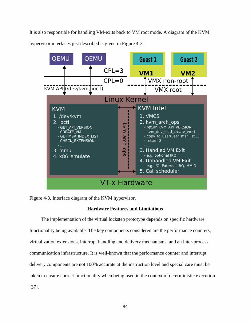
84
It is also responsible for handling VM-exits back to VM root mode. A diagram of the KVM
hypervisor interfaces just described is given in Figure 4-3.
Figure 4-3. Interface diagram of the KVM hypervisor.
Hardware Features and Limitations
The implementation of the virtual lockstep prototype depends on specific hardware
functionality being available. The key components considered are the performance counters,
virtualization extensions, interrupt handling and delivery mechanisms, and an inter-process
communication infrastructure. It is well-known that the performance counter and interrupt
delivery components are not 100% accurate at the instruction level and special care must be
taken to ensure correct functionality when being used in the context of deterministic execution
[37].

85
Performance Counters
The performance counter infrastructure has been present in some form or another in the
Intel processors since the introduction of the Pentium® Pro (P6 family) chip. It consists of a set
of model specific registers (MSRs) that are used to select the events to be monitored and
maintain a count of the events. The first implementation supported the monitoring of two types
of events using 40-bit counters. They could be programmed to count either the events themselves
by incrementing each time an event occurs or the length of the events by counting the number of
processor cycles that occur while an event is true. The capabilities were greatly enhanced for the
Pentium® 4 (NetburstTM family) chips with a total of 18 counters supported, but were then
simplified again when transitioning to the simpler and faster CoreTM
For the purposes of the prototype, only the Core
-based family of chips.
TM-based functionality is considered. One
of the benefits of these versions is that the counters required for enabling deterministic execution
have been specified as architectural, which means that their behavior is guaranteed to be
consistent across processor implementations. Prior to this, all performance monitoring
capabilities were non-architectural, and could vary by processor model. Additionally, the later
generations of CoreTM
The key challenge in using the performance counters for stopping at deterministic
positions in guest operating systems is that they are not designed for such purposes. Rather they
are meant for performance profiling, which does not require perfect accuracy. The events are
processors have further extended the performance monitoring capabilities.
All Xeon processors produced using the 45nm or later process technologies include support for
automatically saving and restoring the performance counter registers when transitioning between
VM root and non-root modes. This simplifies programming of the counters to increment only
during the execution of the guest operating system and not during the execution of the
hypervisor, which would be nondeterministic.
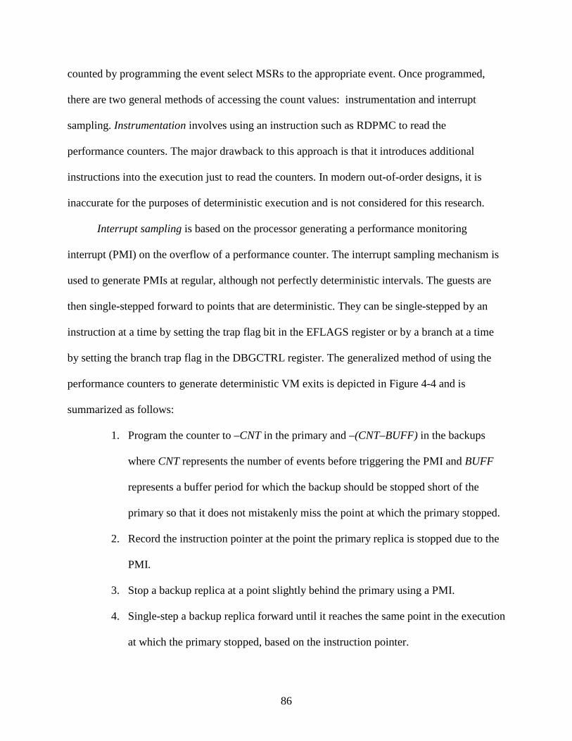
86
counted by programming the event select MSRs to the appropriate event. Once programmed,
there are two general methods of accessing the count values: instrumentation and interrupt
sampling. Instrumentation involves using an instruction such as RDPMC to read the
performance counters. The major drawback to this approach is that it introduces additional
instructions into the execution just to read the counters. In modern out-of-order designs, it is
inaccurate for the purposes of deterministic execution and is not considered for this research.
Interrupt sampling is based on the processor generating a performance monitoring
interrupt (PMI) on the overflow of a performance counter. The interrupt sampling mechanism is
used to generate PMIs at regular, although not perfectly deterministic intervals. The guests are
then single-stepped forward to points that are deterministic. They can be single-stepped by an
instruction at a time by setting the trap flag bit in the EFLAGS register or by a branch at a time
by setting the branch trap flag in the DBGCTRL register. The generalized method of using the
performance counters to generate deterministic VM exits is depicted in Figure 4-4 and is
summarized as follows:
1. Program the counter to –CNT in the primary and –(CNT–BUFF) in the backups
where CNT represents the number of events before triggering the PMI and BUFF
represents a buffer period for which the backup should be stopped short of the
primary so that it does not mistakenly miss the point at which the primary stopped.
2. Record the instruction pointer at the point the primary replica is stopped due to the
PMI.
3. Stop a backup replica at a point slightly behind the primary using a PMI.
4. Single-step a backup replica forward until it reaches the same point in the execution
at which the primary stopped, based on the instruction pointer.

87
There is an additional challenge that an interrupt or exception is counted as an instruction
by the PMC hardware. This can cause inaccuracies when attempting to make the execution
deterministic and must be accounted for. An additional challenging aspect of instruction
performance monitoring is the fact that instructions with the repeat string operand prefix (REP)
are counted as a single instruction for each repetition. The problem with this is that an interrupt
can occur between iterations, which can lead to an unstable execution position. Specifically, the
injection of the interrupt would not occur on an instruction boundary.
Primary replica epoch
Backup replica epoch
PMI TF
Deterministicpoint
Figure 4-4. Deterministic VM exit generation using performance monitor interrupts.
These challenges make ensuring perfectly deterministic PMI behavior very difficult and
the prototype currently does not have full support for this feature. This feature is certainly a
requirement for a production-level implementation of virtual lockstep, however, and has been
shown to work properly when used for similar deterministic execution applications [37]. Future
processors will likely make the capability even more accurate and easier to use for this
application.

88
Virtualization Hardware Extensions
The Intel® Virtualization Technology extensions are a relatively new addition to the
processor hardware and were introduced in the later models of the Netburst-based Pentium 4
microprocessors and later updated and improved for the CoreTM
The key benefits of the virtualization extensions are the simplification of the virtual
machine monitor design and the improved levels of performance typically seen over software-
only mechanisms. The hypervisor maintains complete control over the guest operating system by
defining entry and exit controls, as well as controls that specifically select which events cause
VM-exits to VM root mode. These controls are stored in the virtual machine control structure
(VMCS), and the exit controls are summarized below. Additionally, there are certain instructions
or operations that always cause VM-exits. The combination of these controls ensures that the
hypervisor can regain control of the platform for any type of event that might be
nondeterministic.
-based chips. They were covered
briefly earlier, but there are some specific attributes of the VMX hardware that are important for
the project and a more detailed analysis is provided here.
• Pin-based: Determine if external interrupts and non-maskable interrupts (NMI’s) cause VM-exits or are delivered through the guest’s interrupt-descriptor table (IDT).
• Processor-based: Determine a number of exit reasons, including control register
(CR) accesses, MSR and I/O accesses, and specific instructions such as HLT, INVLPG, MWAIT, RDPMC, RDTSC, MONITOR, and PAUSE. There are also a number of controls for TSC offsetting, interrupt-window exit, and TPR shadowing.
• Exception bitmap: Bitmap representing exceptions with vectors 0-31.
There are certain aspects of the VMX capabilities that are not supported for deterministic
execution in the prototype, however. For example, interrupt and page fault delivery directly to a
guest operating system is fully supported in the virtualization hardware, but allowing these

89
operations would introduce nondeterminism into the system. Therefore, these capabilities are
disabled.
Interrupt Delivery
One of the most important considerations in deterministic replicated execution is interrupt
delivery. Interrupts are asynchronous events that can occur at almost any point in the execution
stream and are often dependent on the specific state of the processor at the time they are handled.
Therefore, delivering an interrupt even a single instruction before or after it was delivered in
another replica is likely to cause a divergence in behavior.
The benefit of the hypervisor-based approach is that nondeterministic interrupt arrival can
be dealt with relatively cleanly. This is possible because physical interrupts can be programmed
to always cause VM-exits to the hypervisor, which can then inject them at deterministic points
using virtual interrupt injection. The hypervisor can request exits on all interrupts simply by
setting the exception control to exit on all vectors. It can also request notification of all external
interrupts and NMI’s by setting the appropriate bit in the pin-based control register. Finally, the
remaining interrupts types, such as INIT and SIPI, are handled since they cause exits
unconditionally.
The difficulty comes with stopping the guest execution at exactly the same instruction
boundary in all replicas so that interrupts can be delivered. The approach taken in the prototype
is to use the boundaries defined by existing deterministic VM exits as the point of interrupt
injection. This technique is insufficient for some workloads since there is no guarantee that an
appropriate rate of deterministic VM exits will occur. This technique can be further enhanced,
however, with the use of performance monitoring interrupts and single-stepping, as described
above, to ensure a minimum rate of deterministic VM exits.

90
Communication Infrastructure
The inter-replica communication considered for the prototype consists of a basic POSIX
shared memory protocol, which does not allow for communication across network devices. The
shared memory regions are configured as a series of bounded broadcast buffers accessed in a
producer/consumer fashion. The primary replica places data to be shared with the backups there
and once all of the backups have retrieved the data, the slot is reused. Accesses to the buffers are
protected using a pthread mutex and condition variable. The specific hardware configurations
supported with this form of IPC are summarized as follows:
• Intra-die: processor cores are on the same silicon die
• Inter-die: processor cores are on the same substrate but not the same die
• Inter-socket: processor cores are on the same motherboard but not the same socket
Prototype Implementation Details
This section details the specific mechanisms used in achieving replicated execution in the
KVM-based prototype. This includes the capabilities necessary to record and replay a
deterministic execution, as well as the logic to detect divergences between the replicas. A
number of challenges were encountered during development in which the only timely solutions
found involved the introduction of a limitation in the prototype that did not impact the goals of
the research but impacted the resultant performance or restricted the model’s capabilities in some
way. The limitations are described in detail in this section and relaxing them is left as future
work.
In modifying the KVM hypervisor to support virtual lockstep, an effort is made to
incorporate as many policy changes as possible into the user-space portion of KVM while only
putting the minimal necessary mechanisms into the kernel modules. The performance may be

91
slightly lower than implementing everything in the kernel modules, but it allows for more safety
and a cleaner, more flexible, and more portable implementation.
Guest State Replication
The first step in implementing replicated execution is to start with a common base among
all replicas. A benefit of a hypervisor-based approach is that the static replication of a guest
virtual machine image is trivial, even if the guest is not in a shutdown state. The entire state of
the guest is represented by the data structures maintained by the virtual machine monitor, the
data in the memory region reserved for the guest, and the virtual hard disk image used as the
guest’s backing store. Static replication of the full guest image is as simple as replicating this
information. For the purposes of the prototype, only static replication is considered and is done
by using the hypervisor’s ability to snapshot the full state of the system to a single QCow2 file
[68].
Guest state replication becomes significantly more complicated if it is to be done
dynamically. The challenge arises because the data to be replicated are constantly changing as
the guest is executing. The most straightforward method is to begin execution of the new
machine on the destination node and then retrieve all pages from the source node on page faults.
Although this is relatively simple to implement, the performance is significantly affected because
of the high overhead of every page fault. There is another well-known method of achieving
pseudo-live migration of a guest, which involves statically replicating all data and then tracking
the changes that dirty pages of memory. These dirty pages are iteratively synchronized across
replicas until they represent a sufficiently small amount, at which point the guests are suspended
for a very short time and the remaining data are synchronized. The total downtime necessary for
the final synchronization is on the order of 10’s to 100’s of milliseconds, which is a short enough

92
time as to not disrupt active network connections or other functionality that would disrupt quality
of service [27], [86].
Guest Synchronization
There are several levels of synchronization that must be achieved depending on the degree
of replication that is considered. The most basic system is a duplex, or two node configuration,
which consists of a single primary and a single backup. The replicas are implicitly synchronized
based on their accesses to the shared buffers used for storing information related to
nondeterministic operations. The primary can only insert an item into a slot of the buffer if it is
not already full; otherwise, it stalls until the backup retrieves its next item. Similarly, the backup
can only retrieve an item if the buffer is not empty and stalls if it is. Access to the shared buffers
is moderated using a pthread mutex and a condition variable that is signaled whenever action is
taken by a replica.
This basic producer/consumer model is rather trivially extended to n-modular redundancy
by allowing for an arbitrary number of backup nodes to retrieve each item. The primary records
for each slot the number of backups that must retrieve the item and cannot reuse a slot until they
all do. An example of this is given in Figure 4-5 in which there is a single primary inserting at
the point marked as in. There are two backup replicas that are retrieving items at two different
positions out[0] and out[1]. The drawback is that the entire system is slowed to the speed of the
slowest backup whenever buffer space is unavailable. This is mitigated to a large extend by
having a reasonable size buffer. In the prototype buffers are typically sized to 50,000 entries with
a single entry being a maximum of 1KB in size.
There are separate buffers created for the I/O values and the interrupts delivered to the
primary replica. The I/O value buffer stores buffer items containing the values the primary uses
for its I/O string and value operations, memory mapped I/O, and RDTSC accesses. These are
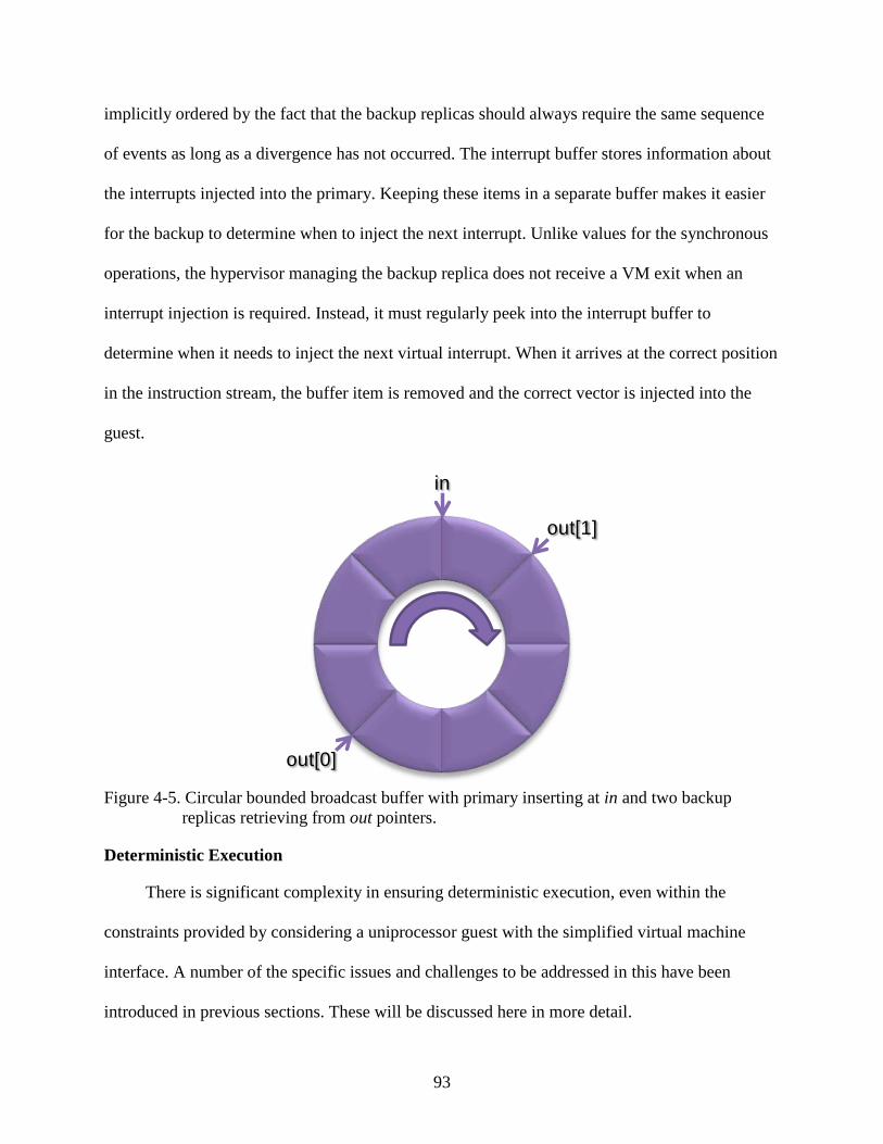
93
implicitly ordered by the fact that the backup replicas should always require the same sequence
of events as long as a divergence has not occurred. The interrupt buffer stores information about
the interrupts injected into the primary. Keeping these items in a separate buffer makes it easier
for the backup to determine when to inject the next interrupt. Unlike values for the synchronous
operations, the hypervisor managing the backup replica does not receive a VM exit when an
interrupt injection is required. Instead, it must regularly peek into the interrupt buffer to
determine when it needs to inject the next virtual interrupt. When it arrives at the correct position
in the instruction stream, the buffer item is removed and the correct vector is injected into the
guest.
in
out[0]
out[1]
Figure 4-5. Circular bounded broadcast buffer with primary inserting at in and two backup
replicas retrieving from out pointers.
Deterministic Execution
There is significant complexity in ensuring deterministic execution, even within the
constraints provided by considering a uniprocessor guest with the simplified virtual machine
interface. A number of the specific issues and challenges to be addressed in this have been
introduced in previous sections. These will be discussed here in more detail.

94
D ND NDD
EINTR
1
Inj1
Pr D
EINTR
2
ND
Inj2
D PD PDD
Inj1
Ba D PD
Inj2
Figure 4-6. Deterministic execution and interrupt delivery with epochs defined by the
deterministic VM exits.
Figure 4-6 is provided to clarify the basic mechanims of virtual lockstep execution. The
figure demonstrates a duplex configuration with a primary and a single backup replica. The flow
along the x-axis represents time that is partitioned into epochs based on deterministic VM exits
to the hypervisor. These epoch boundaries are indicated with vertical dashed lines. Interrupts
being delivered to the primary system are represented by arrows labeled with EINTR and may be
timer interrupts, for example. These interrupts are acknowledged on the physical platform and
handled by the hypervisor, but they are not immediately delivered to the guest operating system,
even in the primary. They must be delayed until an epoch boundary. Ideally, multiple interrupts
could be delivered consecutively at a boundary, but most systems will likely support only one.
D ND ND D ND
EINTR
1
D
Pr1,2 Pr3
Ba1,2Ba3
epoch1 epoch2 epoch3
Pr
Ba
Ba
D
D PD D
D PD D
D
PD D PD D
PD D PD DTime
EINTR
2
EINTR
3
Figure 4-7. Deterministic execution and interrupt delivery with epochs defined by performance
counter interrupt generation.
95
The execution of the instruction stream is labeled as D for deterministic operations, such as
calculations, and ND for nondeterministic operations, such as reading a timestamp. In the backup
replica, the ND operations have values defined by the primary and are labeled PD for pseudo-
deterministic. Finally, the Inj labels at the epoch boundaries represent the actual points of
injection of the virtual interrupt into the guest operating system.
The next diagram, shown in Figure 4-7 demonstrates a more idealized case that is made
possible by PMI generation from the performance counters. In this case, the epoch sizes can be
made regular in duration and minimal rate of them can be assured. This figure also demonstrates
how a second backup would be integrated. It would simply execute concurrently with the first
backup. This model is not fully realized in the prototype, so the remainder of the discussion is
based on the first model, which synchronizes based on existing VM exits.
Another mechanism found to introduce nondeterminism into the prototype is the use of
Unix signals to break out of the main execution loop. This is shown in Figure 4-8, which is a
flowchart of the main execution loop of KVM [68]. It indicates at a high level the transitions
from kernel mode to guest mode in which the guest executes and then drops back to kernel mode
to handle the VM exit. If the VM exit was due to an I/O operation, the flow drops back out to use
mode to handle it using the Qemu device model. When this completes, the cycle resumes. There
is another reason to drop out to Qemu, however, which is if a Unix signal indicates a userspace
Qemu device is ready. Breaking out of the kernel execution loop gives the hypervisor the chance
to do additional processing, which changes the state of the system. This causes issues since all
signal delivery is nondeterministic. In order to ensure determinism, the execution is only allowed
to return back to the user space at deterministic opportunities. This delays the delivery of some
events and has an impact on guest performance, which is analyzed in the next chapter.

96
I/O
Handle I/O SignalPendingYES
Handle Exit
Execute Natively in
Guest Mode
Enter Guest Mode
Issue Guest Execution
IOCTL
NO
YES
NO
User Mode Kernel Mode Guest Mode
Figure 4-8. KVM execution loop diagram [68].
Prototype Limitations
This section summarizes the limitations introduced into the prototype developed as a
research test vehicle. Again, these are limitations that detract from the system executing some
workloads and performing with minimal overhead, but it does not interfere with the stated goals
of this research. A number of limitations of the prototype have already been presented. First,
there are the restrictions that only Intel®-based virtualization is supported and guests must be
uniprocessor. The use of existing VM exits as injection points for virtual interrupts is also a

97
limiting factor since a minimal rate of deterministic exits is not guaranteed. There are also extra
restrictions placed on the scheduling due to signals.
Another limitation placed on the system is the requirement that the replicated guest disk
image is hosted in a ramdisk, which is a portion of main memory used as secondary storage. This
is due to the nondeterminism seen when handling host page faults and has been attributed to
differences in timing when accesses the hard drive. By placing the guest disk images in a
ramdisk, the host does not have to fault pages in. The virtualized guest still has page faults, but
these are deterministic.
The final limitation applied to the prototype is that the KVM hypervisor that is in control
of the virtual lockstep is not fully replicated. The Qeme process, which is userspace portion of
the hypervisor that encapsulates the state of the device models, as well as the majority of the
replication, is fully replicated in the prototype. The kernel portion of KVM is not, however. This
limitation is due to the form of inter-process communication used and the desire to execute
virtual lockstep within a single physical machine. By implementing the broadcast buffer logic as
in a socket-based protocol, it is possible to support execution across physical machines or logical
partitions.
Layered Virtualization
One possible extension to the model as it has been presented is that of layered, or recursive
virtualization [42]. A limitation is imposed by the current model in that a guest virtual machine
that makes use of the hardware virtualization extensions cannot be supported in a fault tolerant
partition. The introduction of the KVM hypervisor at the lowest level precludes a replicated
guest from using the virtualization hardware since recursive virtualization or sharing of the
virtualization resources is not supported.

98
One technique for resolving this issue is through software-based recursive virtualization.
This involves having the lowest-level hypervisor, the modified KVM hypervisor in this case,
virtualize the processor’s virtualization hardware. This not only allows for the execution of an
arbitrary guest in the system, but supports a hypervisor as a replicated guest, which may then
have multiple subguests that are full virtual machines. Through the transitivity of the
relationship, all of the subguests are fully protected by the fault tolerance measures applied to the
guest hypervisor.
The requirements for layered virtualization in Intel architectures are relatively
straightforward in their simplest form. It is necessary to emulate the ten VMX instructions and
the virtual machine control structure (VMCS). The emulation of the instructions is trivial in all
cases except for VMLAUNCH and VMRESUME and can be done by enabling VM exiting on
VMX instructions, performing the necessary steps for emulation, and adjusting the instruction
pointer. The emulation of the VMLAUNCH and VMRESUME instructions, as well as the
emulation of a VM-exit are summarized below.
The guest hypervisor’s accesses to the VMCS are handled as they normally would be by
allowing it to read and write to the VMCS area that it set up in its own memory. This VMCS
area becomes a virtual VMCS that maintains the state of the system from the point of view of
that guest hypervisor. Then, when the guest hypervisor attempts to launch a subguest, the guest
state values of the VMCS are copied to the true VMCS with the exception of the few
components that must be maintained by the true hypervisor (e.g., CR0, CR3, EFER, entry-
control, and exit-control fields). The host state fields of the true VMCS are filled in with values
from the true hypervisor so that it regains control on the subsequent VM-exit. Finally, when the

99
VM-exit does occur, the guest state fields and the exit reason information are copied back to the
virtual VMCS.
If the guest hypervisor needs to be rescheduled, then the host state fields of the virtual
VMCS are used as the guest state fields of the true VMCS. When the VM-exit occurs for that
execution, the guest state fields of the true VMCS are copied back to the host state fields of the
virtual VMCS. Again, the true hypervisor needs to maintain control of key fields of the VMCS,
but the bulk of the data are passed through directly in this fashion.
This chapter covered the development of a virtual lockstep prototype designed to prove out
the model presented in the previous chapter and allow for collection of real performance and
fault tolerance data. The key capabilities are support for fully deterministic execution of a
standard Linux operating system, an arbitrary number of backup replicas, and a powerful
interface for fault injection and monitoring. These features are put to the test in the next chapter
where the performance of prototype is analyzed and in Chapter 6 where the fault injection
capabilities are considered.

100
CHAPTER 5 RELIABILITY MODEL AND PERFORMANCE RESULTS
The goal of this chapter is to summarize the metrics used to analyze the performance of the
proof-of-concept hypervisor design presented in the previous chapter. The performance is
assessed using empirical data collected from a variety of benchmarks and unit tests executed on
real hardware. The tests are chosen to evaluate the feasibility and practically of applying virtual
lockstep technology across a variety of different workloads.
Prototype Test Platform
This section introduces the benchmarks considered in testing the prototype and gives a
short explanation of the guest operating systems on which they are executed. All tests are
executed on the hardware that was detailed in the previous chapter and are done with the guest
operating system pinned to a single core and with no other applications running in the
background.
A number of different guest operating systems are considered when testing the
performance of the virtual lockstep model, which is necessary to assess its potential across a
wide range of possible workloads. The kernels of different operating systems are tuned to certain
use cases and can often vary quite dramatically in their behavior. For example, an operating
system that is geared towards user interactivity and video playback is typically configured with a
higher rate of timer interrupts than one designed for general purpose server applications. An
operating system for embedded or mobile applications may have an even lower rate to conserve
power. The disk and network driver behavior may also vary significantly based on the operating
system and driver design.
The guest operating systems considered throughout the benchmarking workloads are
categorized as follows:

101
• 32-bit Windows®
• 64-bit Windows
guest (home user-based)
®
• 64-bit Linux guest (home user-based)
guest (server-based)
• 64-bit Linux guest (server-based)
• 32-bit Linux guest (simple, text-based)
The reason for these choices of guest operating systems is to encompass the vast majority
of possible system types. Even though the focus of the fault tolerance model is on low- to mid-
range servers, there is future applicability in all areas of computing as the logic error rates and
the processor core counts continue to rise. Different operating systems also tend to exhibit
significantly different behaviors, some of which may be affected a great deal more than other by
the side effects of ensuring deterministic operation.
The specific Windows®-based guest operating systems used are a 32-bit version of
Windows® XP SP3 and a 64-bit version of Windows Server® 2008. This encompasses both the
older kernel used in Windows® XP and the latest kernel used in Windows Server® 2008, which is
the same as that used in Windows Vista® SP1. The 64-bit enterprise version of Linux is CentOS
Server 5.2, which is the binary-equivalent of Red Hat® Enterprise Linux®
The minimal Slackware-based Linux is used in more of the benchmarks and test cases than
others for a number of reasons. First, is that being much smaller allows for more copies to reside
(RHEL) Server 5.2 is
used as the Linux server product and is based on a stable kernel that has performance parameters
tuned to servers. The 64-bit consumer desktop version of Linux considered is Ubuntu 8.04
Desktop edition, which is based on a much later kernel and is tuned to multimedia and Internet
applications. Finally, the 32-bit text-only version of Linux is a minimal Slackware 10.2
installation and is representative of a basic server or embedded system.

102
in the ramdisk necessary for the prototype. Additionally, by being based on a simpler operating
system, it is easier to understand the effects introduced by virtual lockstep in the hypervisor.
Finally, having the operating system source code available for inspection makes debugging
problems easier. For example, by printing the address of the instruction pointer at all points of
synchronization in the virtual lockstep model, it is straightforward to associate specific
operations in question to high-level code on the operating system and gain more context about
what is happening.
All guest operating systems are configured with 1GB of main memory except for the
simple Slackware guest which is given only 128MB of memory, again to reduce the footprint
necessary in the ramdisk area. Each has an IDE disk model and a single Intel e1000-based
gigabit network interface card (NIC) model, which are standard devices provided by the Qemu
userspace device models. The guests are stored in file-backed Qcow2-based images that support
checkpointing and resuming. This consists of storing the running state of the guest to a portion of
the guest image, which allows resuming it at the same state, including the processes that were
running and the state stored in main memory.
In most cases, the benchmarks are most interesting if they generate a high level of virtual
machine monitor interaction. The network- and disk-intensive workloads are generally
considered the best at fulfilling this requirement since they generate a high rate of interrupts and
generally require VM exits on all input and output generated. The specific I/O-based benchmarks
used for the Linux systems are DBench and TBench version 3.5, which are based on the Samba
Netbench suite. DBench models the disk accesses of a Netbench run while ignoring the network
traffic, while TBench models only the network accesses and does not complete the disk accesses.
The corresponding benchmarks used for Windows® are IOMeter for driving a high disk access

103
rate and NTTCP, which drives a high synthetic network load. The reason for choosing these
particular benchmarks is to achieve the highest sustained throughput of disk or network
transactions, which lead to a similarly high level of VM exits and hypervisor interaction.
Additionally, the SQLite database benchmark is executed on the Linux platforms and models
insertions into a database, which is an I/O-intensive process. It is executed using the standard
parameters defined in the Phoronix Test Suite version 1.6 [72].
Workloads that are more processor intensive, however, can for the most part be executed
directly on the physical hardware with little involvement by the hypervisor. This results in a
lower VM exit rate and less interaction between replicas. These types of benchmarks are used to
determine the general performance overhead of the replication protocols. Super Pi is a program
that calculates the digits of pi to an arbitrary level of accuracy. It is used as a very processor
intensive workload on both Windows®
Finally, code compilation is selected as a reasonable compromise between purely processor
and I/O intensive behavior. Both the standard Linux kernel and the MySQL software suite are
targets for compilation. The Linux kernel is compiled single-threaded and using the default
compiler and config file from the guest operating system and the MySQL software suite is
compiled using the standardized benchmark parameters defined by the Phoronix Test Suite. To
clarify, the SQLite benchmark is a SQL database-based benchmark, whereas the MySQL
benchmark is strictly a standardized compilation-based benchmark. Overall, the Linux kernel
compile is used most often throughout the testing given its interesting behavior profile,
especially in a virtualized context, and historical use as a benchmark.
and Linux platforms. The SPEC CPU2000 integer and
floating point benchmark suites are also used for some tests since they are an industry standard
and provide well-known patterns of behavior.
104
Replication and Synchronization Overhead
The first step in replicating a guest operating system is replicating its state across multiple
cores. The state includes all information necessary to run the guest, including the secondary
storage and the dynamic memory image if the guest is saved in a running state. This section
analyzes the size of the state images and the performance costs associated with doing the
replication and maintaining synchronized state.
Replication and Reintegration Costs
The initial data considered are that of the static replication costs for typical guest
configurations. The goal of this analysis is to estimate the typical memory footprint of an
operating system, as well as to determine the approximate replication time. These values are
representative of the time necessary to do the initial guest copy when the system triggers the
dynamic creation of a new replica based on an executing guest image. It also represents the
approximate amount of information necessary for transfer during the reintegration process
following a replica failure.
Table 5-1 shows the size of the compressed snapshots associated with the guest operating
systems, as well as the time required to generate and subsequently duplicate the image on the
hard disk or ramdisk. The replication times are included for both types of media because the
prototype executes guests in a ramdisk and because the speed of the ramdisk storage is much
more representative of the speed of hard disk technology in the near future, when the virtual
lockstep model is expected to be most useful. In fact, there are already products that provide a
battery backup and allow using DRAM as a replacement for a standard SATA drive, and with
new breakthroughs in technologies such as solid state disks (SSD) and phase change memory
(PCM), secondary storage will soon have bandwidth and latency performance approaching that
of modern main memory [58], [70].
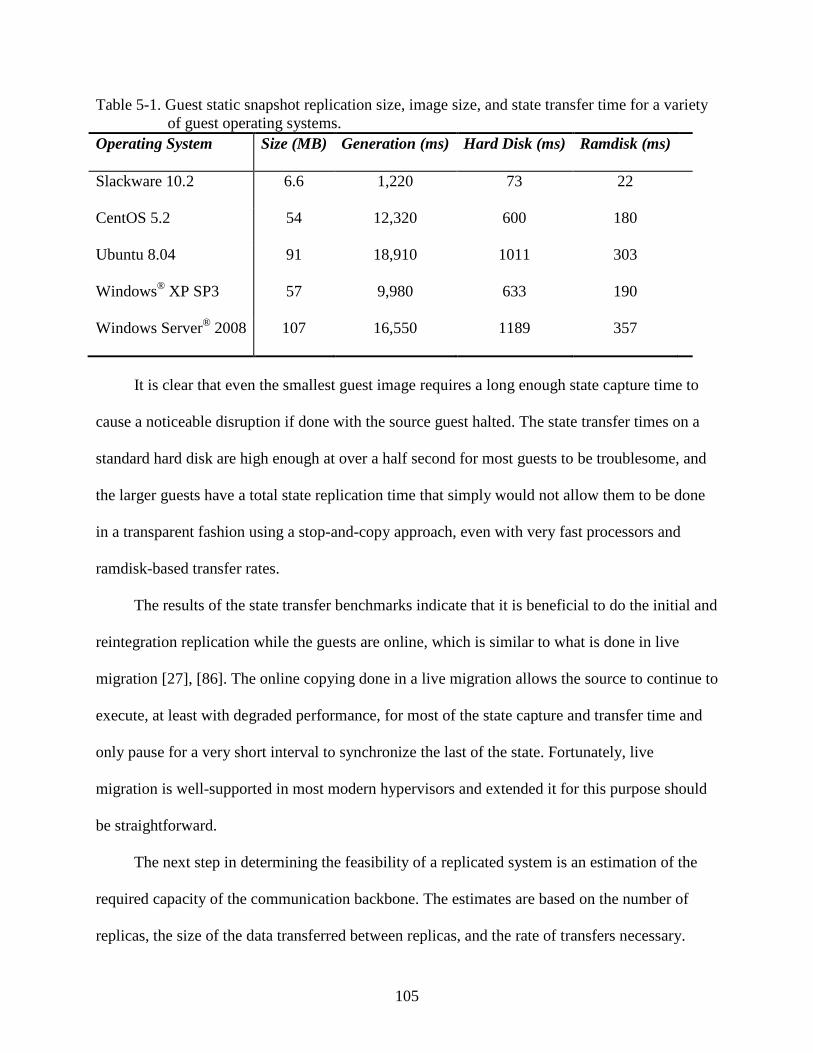
105
Table 5-1. Guest static snapshot replication size, image size, and state transfer time for a variety of guest operating systems.
Operating System Size (MB) Generation (ms) Hard Disk (ms) Ramdisk (ms)
Slackware 10.2 6.6 1,220 73 22
CentOS 5.2 54 12,320 600 180
Ubuntu 8.04 91 18,910 1011 303
Windows® 57 XP SP3 9,980 633 190
Windows Server® 107 2008 16,550 1189 357
It is clear that even the smallest guest image requires a long enough state capture time to
cause a noticeable disruption if done with the source guest halted. The state transfer times on a
standard hard disk are high enough at over a half second for most guests to be troublesome, and
the larger guests have a total state replication time that simply would not allow them to be done
in a transparent fashion using a stop-and-copy approach, even with very fast processors and
ramdisk-based transfer rates.
The results of the state transfer benchmarks indicate that it is beneficial to do the initial and
reintegration replication while the guests are online, which is similar to what is done in live
migration [27], [86]. The online copying done in a live migration allows the source to continue to
execute, at least with degraded performance, for most of the state capture and transfer time and
only pause for a very short interval to synchronize the last of the state. Fortunately, live
migration is well-supported in most modern hypervisors and extended it for this purpose should
be straightforward.
The next step in determining the feasibility of a replicated system is an estimation of the
required capacity of the communication backbone. The estimates are based on the number of
replicas, the size of the data transferred between replicas, and the rate of transfers necessary.

106
These values vary depending on the level of replication applied, the fault tolerance protocol
implemented, the guest operating system behavior, and the workloads that are being replicated.
The worst-case workloads are those that have the highest rate of nondeterministic events and
require the most data to be transferred.
The types of data that must be communicated from a primary to the backup replicas
includes all nondeterministic values read in, as well as timer events, interrupts, exceptions, I/O,
and MMIO data. Additionally, the values transferred via DMA need to be included if DMA is
supported. The first data, presented in Figure 5-1, are the total VM exit rates for a number of
operating system and benchmark combinations. The values represent a normalized VM exit rate
for all exit reasons, averaged over the entire benchmark.
The highest exit rates exceed 180,000 per second and are not constrained to a single
operating system or benchmark. The MySQL compilation and SQLite benchmarks both
approach this value, while the kernel compilation benchmark averages about 60,000 exits per
second. The disk-based benchmarks tend to a lower rate and clock in at around 20,000 exits per
second, although the Windows Server® 2008 IOMeter benchmark hit 100,000 per second. As
expected, the compute-intensive π calculation workloads have very low exit rates for all
operating systems. In summary, this analysis shows that there is easily three order of magnitude
variation between the expected VM exit rates for various workloads and that, in the worst case, it
is not unreasonable to expect a quarter million to occur every second. Many of these exits are
lightweight and do not require a transition to user space, but adding even a small amount of
overhead could have a severe impact to performance. Fortunately, many of these exits are
already fully deterministic and only a small subset of them must be intercepted for virtual
lockstep.
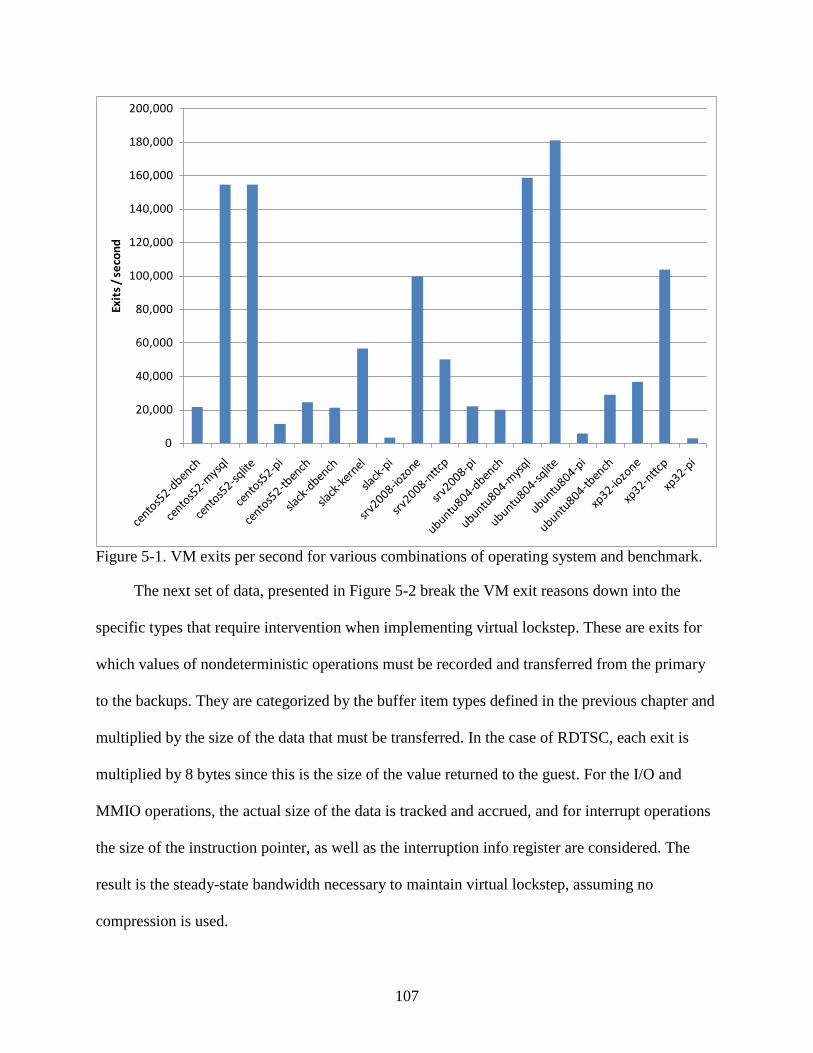
107
0
20,000
40,000
60,000
80,000
100,000
120,000
140,000
160,000
180,000
200,000Ex
its
/ se
cond
Figure 5-1. VM exits per second for various combinations of operating system and benchmark.
The next set of data, presented in Figure 5-2 break the VM exit reasons down into the
specific types that require intervention when implementing virtual lockstep. These are exits for
which values of nondeterministic operations must be recorded and transferred from the primary
to the backups. They are categorized by the buffer item types defined in the previous chapter and
multiplied by the size of the data that must be transferred. In the case of RDTSC, each exit is
multiplied by 8 bytes since this is the size of the value returned to the guest. For the I/O and
MMIO operations, the actual size of the data is tracked and accrued, and for interrupt operations
the size of the instruction pointer, as well as the interruption info register are considered. The
result is the steady-state bandwidth necessary to maintain virtual lockstep, assuming no
compression is used.

108
0
100
200
300
400
500
600
700
800
900Ki
loby
tes
/ se
cond
I/O Read I/O Write MMIO Read MMIO Write RDTSC Interrupt
Figure 5-2. Total bytes per second of nondeterministic data for various combinations of operating system and benchmark.
In most cases, the rate maxes out at approximately 100 KB/s, although a few benchmarks
stand out. Namely, the SQLite benchmarks on the Linux guests and the IOZone benchmark on
the Windows Server® 2008 guest. In all of these cases, there is a very high rate of RDTSC
operations with over 80,000 per second for the SQLite benchmark running on the Ubuntu Linux
guest resulting in a bandwidth requirement of approximately 640 KB/s just for passing
timestamp counter values. Interestingly, Windows XP® does not show the same behavior as
Windows Server® 2008 with regard to reading the timestamp counter, even for the same
benchmark. It apparently uses another means of synchronization. The other benchmark that
stands out is the NTTCP network benchmarks which show a very high rate of virtual interrupts

109
and MMIO accesses, which again indicates how different operating systems can essentially do
the same thing in significantly different ways.
In addition to anticipating the total bandwidth necessary for various workloads, additional
conclusions can be drawn from this last set of data. The first is the property just described, which
is that different operating systems often demonstrate very different behavior for similar, or even
identical, workloads. As such, any production-level implementation of virtual lockstep must take
this into account and find the true worst-case scenarios while avoiding optimizing for a single
operating system or a handful of workloads. Additionally, it is apparent that some hardware
support may be beneficial to reduce the overhead of RDTSC, and possibly virtual interrupt
injection operations. For example, if a deterministic RDTSC operation could be developed or a
method of reducing at least some of the interrupts that must be recorded, the data rate could be
substantially reduced in the worst-case benchmarks.
Virtual Lockstep Benefit Analysis
To estimate the benefit of incorporating the hypervisor into the sphere of replication, data
are presented which show the percentage of time a guest is running on a processor (launched
time) versus the time it is under the control of the hypervisor. The launched time is defined to be
the time the processor is executing code on behalf of the guest and is derived by instrumenting
the hypervisor to record the hardware timestamp counter before each guest resume and again at
each VM exit.
These values are summed over the entire benchmark execution and compared to the total
execution time. The guest is pinned to a single processor and the host in which the hypervisor is
running is otherwise unloaded. This method of accounting results in a worst-case view given that
all idle time, such as when the guest is waiting on the completion of I/O operations or otherwise
halted, is allocated to the hypervisor. It does, however, give insight into the non-negligible time
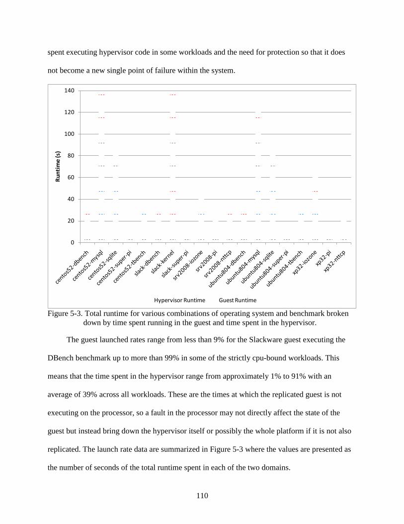
110
spent executing hypervisor code in some workloads and the need for protection so that it does
not become a new single point of failure within the system.
0
20
40
60
80
100
120
140
Run
tim
e (s
)
Hypervisor Runtime Guest Runtime
Figure 5-3. Total runtime for various combinations of operating system and benchmark broken down by time spent running in the guest and time spent in the hypervisor.
The guest launched rates range from less than 9% for the Slackware guest executing the
DBench benchmark up to more than 99% in some of the strictly cpu-bound workloads. This
means that the time spent in the hypervisor range from approximately 1% to 91% with an
average of 39% across all workloads. These are the times at which the replicated guest is not
executing on the processor, so a fault in the processor may not directly affect the state of the
guest but instead bring down the hypervisor itself or possibly the whole platform if it is not also
replicated. The launch rate data are summarized in Figure 5-3 where the values are presented as
the number of seconds of the total runtime spent in each of the two domains.
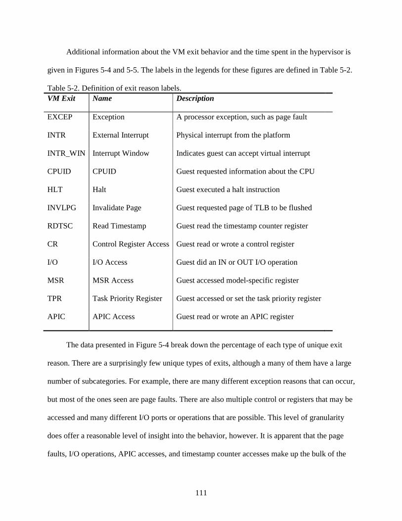
111
Additional information about the VM exit behavior and the time spent in the hypervisor is
given in Figures 5-4 and 5-5. The labels in the legends for these figures are defined in Table 5-2.
Table 5-2. Definition of exit reason labels. VM Exit Name Description
EXCEP Exception A processor exception, such as page fault
INTR External Interrupt Physical interrupt from the platform
INTR_WIN Interrupt Window Indicates guest can accept virtual interrupt
CPUID CPUID Guest requested information about the CPU
HLT Halt Guest executed a halt instruction
INVLPG Invalidate Page Guest requested page of TLB to be flushed
RDTSC Read Timestamp Guest read the timestamp counter register
CR Control Register Access Guest read or wrote a control register
I/O I/O Access Guest did an IN or OUT I/O operation
MSR MSR Access Guest accessed model-specific register
TPR Task Priority Register Guest accessed or set the task priority register
APIC APIC Access Guest read or wrote an APIC register
The data presented in Figure 5-4 break down the percentage of each type of unique exit
reason. There are a surprisingly few unique types of exits, although a many of them have a large
number of subcategories. For example, there are many different exception reasons that can occur,
but most of the ones seen are page faults. There are also multiple control or registers that may be
accessed and many different I/O ports or operations that are possible. This level of granularity
does offer a reasonable level of insight into the behavior, however. It is apparent that the page
faults, I/O operations, APIC accesses, and timestamp counter accesses make up the bulk of the

112
exits in most benchmarks. This narrows down the scope of the performance tuning to only a few
different operations. As long as minimal overhead is added to each of these operations, the total
performance impact should also be minimal. Fortunately, the only exit type that is
nondeterministic in most cases is the timestamp counter read, which is validated by the
bandwidth estimation previously discussed in Figure 5-2. There are some instances where page
fault handling may occur nondeterministically, likely due to spurious page faults, but this should
be manageable by most hypervisors. The I/O operations also require intervention to record the
values of the operations.
0%
10%
20%
30%
40%
50%
60%
70%
80%
90%
100%
% o
f Tot
al E
xits
EXCEP INTR INTR_WIN CPUID HLT INVLPG RDTSC CR I/O MSR TPR APIC
Figure 5-4. Break down of the VM exit reasons while executing the test workloads.
Figure 5-5 breaks down the percentage of time spent by the hypervisor in the handling of
each of the VM exit reasons that showed up as a non-negligible percentage of the total time. The

113
remaining reasons account for the few plots that don’t extend the full length of the y-axis. In the
case of the I/O-bound workloads, it is apparent that much of the time is spent with the processor
waiting in a halted state for the work to do and a smaller percentage of the time handling page
faults and accessing the APIC. There is also obvious variation across operating systems. For
example, Windows Server® 2008 does not halt during the I/O Zone benchmark as Windows®
0%
10%
20%
30%
40%
50%
60%
70%
80%
90%
100%
% To
tal H
andl
ing
Tim
e
EXCEP INTR INTR_WIN CPUID HLT INVLPG RDTSC CR I/O MSR APIC
XP
does.
Figure 5-5. Percentage of total runtime spent in the hypervisor broken down by the specific exit
reasons while executing the test workloads.
Many of the cpu-bound workloads, on the other hand, are dominated by I/O operations and
page faults, with some time spent also accessing the APIC and control registers. The few items
that stand out are the high overhead of handling all the page faults in the MySQL compilation, as
well as the expected high rate of I/O writes that occur during the SQLite benchmark. These data
114
indicate that in some of the worst-case benchmarks in terms of total VM exits, there is a
significant amount of time that is spent halted, which should act as a buffer to offset the extra
processing requited for virtual lockstep operation. It also shows that much of the remaining time
spent in the hypervisor is allocated to handling the I/O operations, which is where much of the
recording is done for virtual lockstep. As long as the inter-replica communication buffer as fast
as or faster than the I/O devices in the platform, the resultant handling time should be no more
than half speed.
Virtual Lockstep Performance Overhead
The data presented in this section indicate the performance overheads seen in the virtual
lockstep prototype. The comparisons are made by evaluating the performance of the guest
operating system being virtualized using the standard KVM-33 hypervisor versus the
performance of the same guest image running on the virtual lockstep capable version of KVM-
33. All benchmarking is done using the test platforms described in the previous chapter and the
guest operating system used is a standard installation of the 32-bit Slackware 10.2 Linux
distribution.
The data presented in Table 5-3 indicate the percentage of performance overhead
introduced in a standard Linux kernel compilation. The kernels used include the version 2.4.31
kernel that is part of the Slackware 10.2 operating system, as well as a Linux 2.6.20 kernel
downloaded from the public Linux repository. The compilation times are recorded separately for
the primary and the backup replica since the backup tends to lag slightly behind the primary.
Times are given for the virtualized case, which is running the standard KVM hypervisor, and the
lockstepped case, which makes use of the custom KVM hypervisor with virtual lockstep support.
The rate of deterministic exits is also given, which gives an indication of the rate at which

115
interrupts can be injected into the guest. Finally, the percentage overhead in terms of additional
compile time is given.
The 2.4.31 kernel is much smaller and simpler than the 2.6.20 kernel and incidentally has a
much higher percentage overhead associated with it. The first indication of the reason for this is
seen in the deterministic VM exit rate, which is significantly lower than for the larger kernel
compile. This means interrupts are delayed by a larger amount, on average.
Table 5-3. Virtual lockstep performance overhead summary. Primary Virtualized Lockstepped Det. VM Exits Exits/s Overhead
Linux 2.4.31 128.5s 135.1s 568K 4,204 5.1%
Linux 2.6.20 255.3s 258.8s 1.568M 6,059 1.4%
Backup
Linux 2.4.31 128.5s 135.6s 568K 4,189 5.5%
Linux 2.6.20 255.3s 259.2s 1.568M 6,049 1.5%
The data presented in Figure 5-6 demonstrate the performance of the virtual lockstep
replica under varying degrees of fault tolerance, as well as varying sizes of the inter-replica
bounded broadcast buffer. The same kernel compile benchmark is used as the previous tests,
although the execution is done on the faster of the two hardware platforms used in testing, which
results in the numbers being slightly faster. The values are also the average of at least 30 runs of
each configuration and have a very low variance.
The configurations considered range from a single backup (dual-modular redundant) up to
three backups (quad-modular redundant), which is the limit of the quad-core hardware being
used. The size of the buffer is varied from 5,000 entries up to 80,000 entries. Given that each

116
buffer entry is approximately 1KB in size, the total size of the buffer then ranges from
approximately 5MB to 80MB.
0
20
40
60
80
100
120
140
DMR5k
DMR10k
DMR 20k
DMR40k
TMR5k
TMR10k
TMR20k
TMR40k
QMR5k
QMR10k
QMR20k
QMR40k
QMR80k
Tim
e (s
)
Primary Time Backup 1 Time Backup 2 Time Backup 3 Time
Figure 5-6. Total run-time of primary and either one replica (dual-modular redundant), two replicas, (triple-modular redundant), or three replicas (quad-modular redundant) with a shared buffer size ranging from 5,000 entries to 80,000 entries.
It is apparent that the coordination of the extra replicas has a small performance penalty
associated with it. That is the single-backup configuration runs slightly faster in all cases than a
dual-backup configuration. These both execute slightly faster than the triple-backup
configuration. Also, while increasing the size of the buffer shows little benefit when a single
backup is used, it does offer a noticeable improvement for the other levels of redundancy, at least
to an extent. The performance of the primary continues to improve as the buffer is increased
since it allows the backups to lag further behind, but what really matters is the overall runtime in

117
which all replicas finish the task. The optimal overall runtime for the dual-backup case is at
10,000 entries, while performance continues to improve in the triple-backup case all the way out
to 40,000 entries.
Most importantly, these data indicate that higher degrees of replication are practical in
terms of performance, although they are quite expensive in terms of additional hardware. It is
reassuring, however, for very high levels of redundancy to be transistor count limited rather than
transistor performance limited, given that Moore’s Law and the direction of the industry is to
continually improve the transistor counts. Additionally, the data indicate that tuning of the buffer
size plays an important role in optimizing performance and that bigger doesn’t always result in
better overall performance.
This chapter covered the benchmarking done for the initial scoping of the virtual lockstep
prototype, as well as the real-world performance data gathered from the prototype
implementation. The goals of the initial benchmarks were to highlight important parameters
related to realizing virtual lockstep. This included determining which types of VM exits are
nondeterministic, the average rate of these exits, and the total number of bytes expected to be
transferred in both initiating and maintaining virtual lockstep.
Then, in analyzing the performance of the working prototype, data were presented that
gauge the performance penalty incurred when compared to standard virtualization. The
parameters of the replication were also varied to demonstrate the high degrees of replication are
practical from a performance perspective and that the tuning of the communication buffer is an
important part of determining the overall virtual lockstep performance.
118
CHAPTER 6 FAULT INJECTION AND VIRTUAL PROCESSOR STATE FINGERPRINTING
This chapter covers an enhancement to the virtual lockstep model in which faults in the
system are detected much sooner than by the typical method of monitoring the output generated
by the processor. The values in the registers representing the state of the virtual processor are
hashed into unique fingerprints that are regularly compared across replicas. The benefits of this
approach are analyzed using a powerful register-based fault injection capability that is made
possible by the virtual lockstep model.
Fault Injection Model
In order to test the efficacy of the proposed fault detection mechanism, it is necessary to
have a fault injection infrastructure in place. The model of fault injection considered is based on
the perturbation of processor register state in the form of single event upsets (SEUs) that
represent a particle striking a bit and causing the value to change or possibly a bit failing to due
to wear-out effects. The model takes advantage of the control the hypervisor maintains over the
state of the guest operating system to introduce the bit failures by changing the values stored in
system registers.
Fault Injection Details
As described previously, the hypervisor is responsible for maintaining the virtual processor
state representing the guest system it is hosting, and in order to improve performance, some of
the state handling may be done with hardware assistance. In fact, in KVM-based virtual lockstep
prototype many of the register values representing the virtual processor state of the guest are
stored in the VMCS structure. Those that are not must be manually saved and restored by the
hypervisor each time the guest exits to the hypervisor or is resumed, respectively. Additionally,
most hypervisors, including KVM, already have mechanisms defined for consolidating the guest

119
state so that it can be migrated to another system or a snapshot can be saved for recovery at a
later time.
Injecting a fault into a register of a running guest virtual machine is relatively
straightforward. The virtual machine model has a clear boundary defining when the guest state is
transferred to the processor for the resumption of execution. Fault injection is done by modifying
the hypervisor to access the register at this point and inject a bit flip by doing an exclusive OR
operation on the register with a bitmask that has a one set for the bit position that has been
targeted for corruption. The faulty register is then loaded into a physical register on the processor
and execution progresses as if the bit had been struck by a particle. Stuck-at and multi-bit faults
can modeled in a similar fashion by changing the logic operation or bit mask being applied to the
register.
Fault Propagation Analysis
In order to detect the divergence in behavior the fault causes, if any, it is necessary to have
a baseline to compare the execution to. Unfortunately, this is not as simple as executing the
benchmark on the system once and then comparing the behavior to a second run when a fault is
injected. The reason is that guest execution varies slightly each time it is run. For example,
asynchronous events, such as interrupts, are delivered at different points in time and values read
from input sources, such as the timestamp counters, vary by run. The problem is that all of these
types of nondeterministic events that cause divergence in behavior cannot be distinguished from
a divergence that is caused solely from the injection of a faulty bit.
This is where the virtual lockstep functionality comes into play. The technique proposed in
this dissertation is to execute a duplex system in virtual lockstep so that it has all of the
nondeterminism removed and then inject faults into only the backup replica while the primary
continues to define the behavior of the system. Alternatively, a deterministic recording could be

120
taken and then replayed multiple times with a different fault injected each time. In either case,
the execution is known to be repeatable.
When a divergence does occur, it can be attributed to the bit flip, at least up to the point at
which an incorrect type of value is passed from the primary to the backup. As described in
Chapter 3, if the backup diverges in such a way that it arrives at a point of requiring a value for a
particular type of operation, but the next operation for which the primary has defined a value for
is of another type, it does not prove beneficial to continue execution. The act of giving the
backup the values in a different order than was defined by the primary does not provide
additional useful information since that in itself is expected to cause a divergence. In fact, the
primary may not have even defined such a value. Specifically, the behavior of interest is the
execution of the backup from the point of the fault injection until the point at which it either fails
or requires the introduction of an additional form of nondeterminism. Of course, the execution
may not diverge, in which case the fault was either masked or planted as SDC waiting to be
exposed at a later time.
Processor State Comparisons
A major limitation of detecting fault using the comparison of deterministic input value
types and output values is the delay possible from the point of injection until the error is
observed. This delay makes checkpoint and restore operations much less efficient since there is a
significant chance that the checkpoints may be recorded with the fault present but not yet
exposed [24]. This results in having to maintain multiple checkpoints and having to iteratively
try recovering from them until one is found that is old enough to not contain the fault.
Additionally, the average detection delay limits the rate at which checkpoints can be taken.
This is troublesome since high-speed checkpointing is considered to be a possible mechanism for
achieving virtual lockstep-like operation for multi-processor guests. One technique that can be

121
used for reducing the fault detection delay is to monitor the internal processor state at regular
intervals. The processor state being considered is composed of the registers in the processor core.
This section introduces virtual processor state fingerprinting, which takes advantage of the
processor state structures maintained by the hypervisor to detect divergence before they appear at
the I/O interface of the processor.
Virtual Processor State Fingerprinting
Since the hypervisor must maintain the register state of its virtual guests, it is
straightforward to access this information on any VM exit and compare it across replicas. The
size and number of registers vary by architecture, and even by model within a given architecture,
but the total size of all the registers in most modern processors is on the order of kilobytes. This
makes it impractical to transfer and compare the complete register state among all replicas. Since
the goal is to detect faults significantly earlier than I/O-based comparisons, the state must be
compared very often—ideally on every VM exit. If this were the case, the amount of data
transferred for the state comparisons would far outweigh the amount of data required to maintain
virtual lockstep.
Processor state fingerprinting is an optimization that can be applied to reduce the amount
of data being transferred between processors. It also simplifies the comparison at the cost of
extra computation necessary to compute the fingerprint. It works by hashing the register state of
the virtual processor into a unique fingerprint that is transferred and compared. The one major
drawback of this approach is that it loses information about exactly which state has diverged, but
this is typically not necessary to have. Simply knowing that an error is present is sufficient
information to trigger a rollback to a known good state.
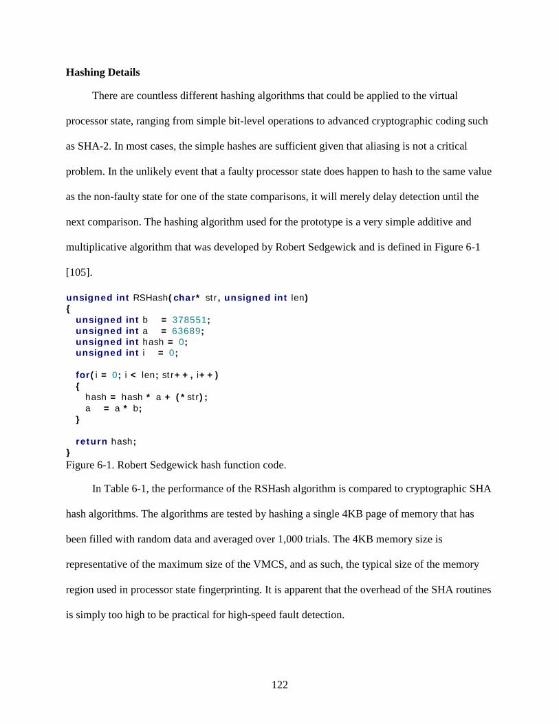
122
Hashing Details
There are countless different hashing algorithms that could be applied to the virtual
processor state, ranging from simple bit-level operations to advanced cryptographic coding such
as SHA-2. In most cases, the simple hashes are sufficient given that aliasing is not a critical
problem. In the unlikely event that a faulty processor state does happen to hash to the same value
as the non-faulty state for one of the state comparisons, it will merely delay detection until the
next comparison. The hashing algorithm used for the prototype is a very simple additive and
multiplicative algorithm that was developed by Robert Sedgewick and is defined in Figure 6-1
[105].
Figure 6-1. Robert Sedgewick hash function code.
In Table 6-1, the performance of the RSHash algorithm is compared to cryptographic SHA
hash algorithms. The algorithms are tested by hashing a single 4KB page of memory that has
been filled with random data and averaged over 1,000 trials. The 4KB memory size is
representative of the maximum size of the VMCS, and as such, the typical size of the memory
region used in processor state fingerprinting. It is apparent that the overhead of the SHA routines
is simply too high to be practical for high-speed fault detection.
unsigned int RSHash ( char * str , unsigned int len ) { unsigned int b = 378551 ; unsigned int a = 63689 ; unsigned int hash = 0 ; unsigned int i = 0 ; for ( i = 0 ; i < len ; str ++, i ++) { hash = hash * a + (* str ); a = a * b ; } return hash ; }

123
Table 6-1. Hashing performance of various algorithms for a random 4KB page of memory. Algorithm Hash time (s)
RS-128 0.57
SHA-224 8.28
SHA-256 8.39
Fingerprinting Optimizations
There are a number of additional optimizations that are applicable to the virtual processor
state fingerprinting process. The first is the use of hardware-based virtualization extensions and
data structures to facilitate hardware-based performance enhancements. As described in Chapter
2, the Intel architecture defines the VMCS is used to store the most important virtual processor
state of a guest, as well as a number of control and status fields. This structure is stored in
memory and is under full control of the hardware. In fact, the hypervisor does not even know the
layout of the memory and must use accessor instructions to read from it and write to it. The fact
that it is controlled by hardware makes it simple to optimize with specialized hardware or
microcode. For example, circuitry could be added to the chip to do the fingerprinting or it could
be done with an idle core on the processor. This significantly reduces the overhead associated
with doing the hashing.
The second optimization is the possibility of selective state filtering based on fault
detection behavior analysis. As is demonstrated later in this chapter with the data collected using
the prototype hypervisor, not all state is necessary to achieve the benefits of early fault detection.
That is, there are certain registers, or in the case of the prototype, certain VMCS fields that are
more sensitive to fault injection than others. By conducting many trials while injecting faults at
random points in the execution of programs, it is possible to determine which registers or fields

124
most often fail. The hashing can be further optimized by only including these items in the
computation.
Yet another optimization is in the transfer of the fingerprint among replicas in a system
that is configured with triplex or greater level of redundancy. Rather than having all replicas send
the fingerprint to all other replicas, any divergences can be stored within the buffer. This works
by locking the broadcast buffer entries and having the first backup to detect a divergence store
the fingerprint it generated along with the fingerprint that was stored there by the primary. When
the next backup accesses that position, it detects the additional fingerprint value and is able to
vote on which is correct. Of course, if the second backup detects a divergence that the first did
not, it will store its fingerprint value there but it will not matter since a majority of replicas have
already proceeded past that point.
KVM Prototype Fault Injection
Fault Injection Overview
For the purposes of data collection in this research, the targets for fault injection are limited
to the system, control, and general purpose registers in the processor. These are summarized in
Table 6-2, which uses a common shorthand representation that is read as R[S,D]I is RSI and
RDI. The injection of faults into memory regions such as the stack, heap, or active memory of
the guest are interesting but are not within the scope of this work. Such modeling could easily be
done using the same technique described above, but it is assumed that the memory is already
well protected by ECC within the modules and possibly mirroring across modules.
The two bit positions targeted for fault injection in most registers are 4 and 16. The main
reasoning for this is to flip both a lower-order bit so that the affected value, often an address, will
move only a small amount (e.g., between two and 16 instructions in the case of RIP), as well as a
higher-order bit to cause a more significant change in the value. For registers in which bits are

125
defined for special purposes, such as the control registers and the RFLAGS register, all
meaningful (i.e., not reserved) individual bits have been targeted. This targeted approach
provides more concise information with fewer runs than fault injection methods that randomly
inject into all bits in all registers. It is especially useful to be able to relate functionally
significant bits such as those in the control registers to the behavior observers after the fault
injection.
Table 6-2. Fault injection target registers and their inclusion in the VMCS. Register VMCS Description
RIP, RSP Y Instruction and Stack Pointers
RBP N Base Pointer
RFLAGS Y Flags Register
R[S,D]I Y String Op Source and Destination
CR[0,3,4] Y Control Registers
[C,D,E,F,G,S]S Y Segment Register Base Pointers
TR Y Task Register
[I,L,G]DTR Y Descriptor Table Base Pointers
R[A,B,C,D]X N General Purpose Registers
The data presented below are based on faults that are injected during a standard
compilation of the Linux 2.4.31 kernel. The time of the injection is varied randomly for each trial
and repeated a minimum of 500 times for each bit position. The compilation is run for 10,000
deterministic exits as a warm-up phase plus a random number of additional deterministic exits
from 1 to 216 before the fault is injected into the bit. After injection, the guest is run for at least
126
100,000 additional deterministic exits, which is on the order of the runtime considered in related
work [73], [75], [100].
There is a possibility that a fault injection into a guest may cause the host platform to crash
or hang, especially when it causes a significant disruption to the platform, such as changing the
paging mode. Once the paging mode is changed, the page tables are walked incorrectly by the
hardware and may direct certain operations to invalid portions of memory or memory that
belongs to another guest. Behavior in which the host kernel was corrupted and crashed was
observed approximately 2% of the fault injection trials targeting the CR0 and CR3 control
registers and occasionally for some of the RFLAG register bits. The detailed results are provided
in the next section of this chapter.
These fatal host kernel crashes may be reduced or avoided by implementing certain
protection mechanisms in the fault injection architecture [73]. Protection on real hardware is
possible by replicating across physically or logically partitioned systems so that the memory
regions of the hosts are protected from one another. This eliminates the possibility of the guest
affecting the memory of other hypervisors or other guest virtual machines. It is for this extra
degree of protection that partitioned replication is the preferred configuration for the generalized
virtual lockstep model.
Fault Injection Performance Results
The results of fault injection into the virtual lockstep prototype are detailed in the
following graphs. These results are based on single bit flip injection into registers of the backup
replica while executing a kernel compile in a Slackware 10.2 guest virtual machine. The registers
injected into are labeled in the plots according to the nomenclature defined in Table 6-2, and the
bit positions targeted are labeled in braces and are based on the bit selection process defined
previously.

127
The first fault injection data considered are presented in Figures 6-2 through 6-7 and are
the high-level behavior of the guest virtual machine after the fault injection. These are
categorized into one of four categories: Crash, No Crash, Hang, and Lockstep Fail. The Crash
case means that the guest failed in some fashion in which the hypervisor and the guest kernel are
aware of the crash. An example of this is when Linux does a core dump and shuts down or the
equivalent is a Windows®
The lockstep failure happens when a divergence in execution occurs between the replicas
that causes different types of deterministic exit reasons to be generated. For example, if the
primary replica generates a RDTSC value but the backup has diverged in such a way that it
requires an I/O value instead of the RDTSC, the system is shut down. It does not make sense to
provide the deterministic values out of order, as they may not even exist.
blue screen. The few cases in which the host kernel crashes are also
included in this category. No Crash means that the kernel compile continued for at least the
100,000 additional deterministic VM exits after injection, or until completion of the compilation.
In other words, the guest ran apparently unaffected with the detection of a fault by the inherent
mechanisms of virtual lockstep. The Hang category includes cases in which the guest gets into
an endless loop and does not crash but instead hangs the CPU it is executing on. Finally, the
Lockstep Fail category defines cases in which virtual lockstep can no longer be maintained.
Guest hangs are limited to the process encapsulating the virtual machine and are detected
using a form of software watchdog timer that looks at the number of total VM exits and
compares it against the pre-determined upper bound on the number of VM exits that should
occur during the kernel compilation. This works since the total VM exit count continues to
increment, due to platform external interrupts for example, even if the guest execution is stuck in
a loop.

128
When the total number of VM exits reaches 50% more than a target value that was
determined from preliminary test executions, a special VM exit reason that has been defined
explicitly for this purpose is taken to force the hypervisor out of kernel mode and allow the guest
to be cleanly killed. If this were not done, the Qemu process encapsulating the virtual machine
would be uninterruptible and as such, not killable without resetting the physical platform.
0%
10%
20%
30%
40%
50%
60%
70%
80%
90%
100%
% T
rial
s
Register [bit]
Crash No Crash Lockstep Fail Hang
Figure 6-2. Fault injection failure distribution for control registers.
Figure 6-2 depicts the failure distribution of the system control registers and Tables 6-3
through 6-5 describes the meaning of the bits considered in these registers. As their name
suggests, the control registers control the operating mode of the processor. CR0 has controls for
paging, memory caching and write protection, floating point operation, and task switching. As
seen in the results, this register is obviously very sensitive to fault injection and crashes the guest

129
nearly 100% of the time, while occasionally bringing down the host with it. The two bits that
stand out slightly for crashing the host platform are bit 0, which changes the execution mode of
the processor, and bit 31, which changes the paging mode of the processor. These are both very
disruptive changes and it is actually surprising that the host is not affected more often given that
no special support was implemented for protecting it.
Table 6-3. Control register CR0 bit descriptions. Bit Description
0 PE – Executes in real-mode when clear and protected mode when set
1 MP – Defines interaction of WAIT/FWAIT instructions with task switch flag
2 EM – Disables floating point support when set
3 TS – Allows delayed saving of floating point state on task switch
16 WP – Write protects user-mode read-only pages from supervisor-mode writes
31 PG – Enables memory paging when set and disables it when clear
The CR3 register contains the base address of the guest’s memory region, as well as flags
controlling the caching behavior of the chip. Not surprisingly, the bits controlling the caching
behavior, bits 3 and 4, are not very sensitive and only very rarely cause a disruption. The higher-
order bits, which are those defining the base address for memory paging hierarchy, do however,
cause the system to fail if they are altered—again bringing down the host from time to time.
There is little difference in the degree to which the paging base, which is defined by the higher
order bits of the register, is altered, as both bit positions result in essentially equivalent behavior
in terms of crashing.
Table 6-4. Control register CR3 bit descriptions. Bit Description
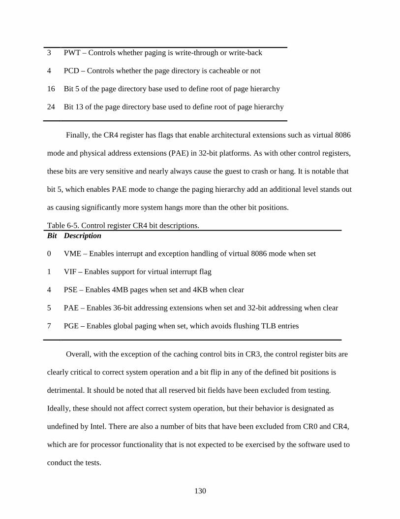
130
3 PWT – Controls whether paging is write-through or write-back
4 PCD – Controls whether the page directory is cacheable or not
16 Bit 5 of the page directory base used to define root of page hierarchy
24 Bit 13 of the page directory base used to define root of page hierarchy
Finally, the CR4 register has flags that enable architectural extensions such as virtual 8086
mode and physical address extensions (PAE) in 32-bit platforms. As with other control registers,
these bits are very sensitive and nearly always cause the guest to crash or hang. It is notable that
bit 5, which enables PAE mode to change the paging hierarchy add an additional level stands out
as causing significantly more system hangs more than the other bit positions.
Table 6-5. Control register CR4 bit descriptions. Bit Description
0 VME – Enables interrupt and exception handling of virtual 8086 mode when set
1 VIF – Enables support for virtual interrupt flag
4 PSE – Enables 4MB pages when set and 4KB when clear
5 PAE – Enables 36-bit addressing extensions when set and 32-bit addressing when clear
7 PGE – Enables global paging when set, which avoids flushing TLB entries
Overall, with the exception of the caching control bits in CR3, the control register bits are
clearly critical to correct system operation and a bit flip in any of the defined bit positions is
detrimental. It should be noted that all reserved bit fields have been excluded from testing.
Ideally, these should not affect correct system operation, but their behavior is designated as
undefined by Intel. There are also a number of bits that have been excluded from CR0 and CR4,
which are for processor functionality that is not expected to be exercised by the software used to
conduct the tests.

131
0%
10%
20%
30%
40%
50%
60%
70%
80%
90%
100%
CS[4] CS[16] DS[4] DS[16] ES[4] ES[16] SS[4] SS[16] FS[4] FS[16] GS[4] GS[16]
% T
rial
s
Register[bit]
Crash No Crash Lockstep Fail Hang
Figure 6-3. Fault injection failure distribution for segment registers.
The segment base registers are considered in Figure 6-3. These are part of the series of
registers that define each segment used in the processor. In addition to the base registers, there
are corresponding limit and access right registers which are not considered in the fault injection
testing. The base registers identify the beginning addresses for each segment and are used as an
offset for indexing into the memory regions they define. The CS, DS, and SS registers are
defined as the code segment, data segment, and stack segment, respectively. The remainder, ES,
FS, and GS are additional data segments that may or may not be use by software. This
description aligns well with the results of the fault injection, in which CS, DS, and SS practically
always cause a crash, where ES, FS, and GS result in a guest failure at a much lower rate.
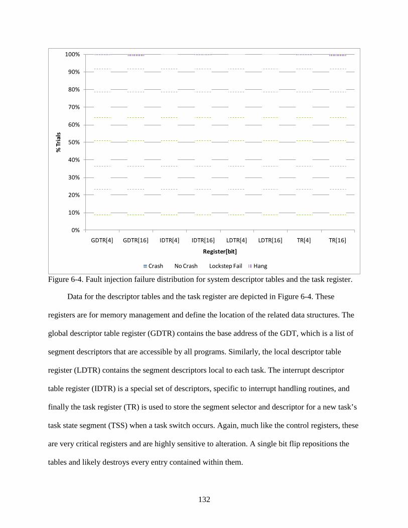
132
0%
10%
20%
30%
40%
50%
60%
70%
80%
90%
100%
GDTR[4] GDTR[16] IDTR[4] IDTR[16] LDTR[4] LDTR[16] TR[4] TR[16]
% T
rial
s
Register[bit]
Crash No Crash Lockstep Fail Hang
Figure 6-4. Fault injection failure distribution for system descriptor tables and the task register.
Data for the descriptor tables and the task register are depicted in Figure 6-4. These
registers are for memory management and define the location of the related data structures. The
global descriptor table register (GDTR) contains the base address of the GDT, which is a list of
segment descriptors that are accessible by all programs. Similarly, the local descriptor table
register (LDTR) contains the segment descriptors local to each task. The interrupt descriptor
table register (IDTR) is a special set of descriptors, specific to interrupt handling routines, and
finally the task register (TR) is used to store the segment selector and descriptor for a new task’s
task state segment (TSS) when a task switch occurs. Again, much like the control registers, these
are very critical registers and are highly sensitive to alteration. A single bit flip repositions the
tables and likely destroys every entry contained within them.

133
0%
10%
20%
30%
40%
50%
60%
70%
80%
90%
100%
RAX[4] RAX[16] RBX[4] RBX[16] RCX[4] RCX[16] RDX[4] RDX[16]
% T
rial
s
Register[bit]
Crash No Crash Lockstep Fail Hang
Figure 6-5. Fault injection failure distribution for general purpose registers.
As indicated by their name, the general purpose registers (GPRs) in Figure 6-5 are used for
a variety of operations. The general usage model is as follows: RAX is the accumulator for ALU
operations, RBX is a pointer into the data segment, RCX is a counter, and RDX is an I/O pointer.
In general, faults in these registers only results in crashes, or failed lockstep execution, about 5%
of the time. This is not surprising since a fault is significantly more localized than it is with a
segment base or a control register. A fault introduced into one of these registers likely just causes
a single value to be changed, an incorrect memory address to be accessed, or a loop to be
executed an incorrect number of times. There seems to be little correlation between the bit
position and the rate of failure. That is the higher bit causes a higher failure rate in RAX and
RBX, but a lower failure rate in RCX and RDX. None of these fault types appear to lead to

134
system hangs or crashes and instead the faults that are detected are done so by the virtual
lockstep process.
0%
10%
20%
30%
40%
50%
60%
70%
80%
90%
100%
RBP[4] RBP[16] RSP[4] RSP[16] RIP[4] RIP[16] RSI[4] RSI[16] RDI[4] RDI[16]
% T
rial
s
Register[bit]
Crash No Crash Lockstep Fail Hang
Figure 6-6. Fault injection failure distribution for various system registers.
Next is Figure 6-6, which includes additional system registers. In particular, there is the
base pointer (RBP), stack pointer (RSP), instruction pointer (RIP), and string source (RSI) and
destination (RDI) registers. These each serve unique purposes. RBP points to data on the stack,
RSP points to the stack itself, RIP indicates the next instruction to be executed, and RSI and RDI
indicate the source and destination for string operations.
The most critical registers are RSP and RIP, which cause guest failure with a high
probability. It is observed that moving RSP even a small amount, by altering bit 4 versus bit 16,
is enough to cause a crash is most cases. On the other hand, moving the RIP by only 16 bytes,

135
which represents only a few instructions, is less likely to cause a failure than moving it by 64KB.
It does make sense that skipping or repeating a few instructions is less critical to system stability
than jumping much further. Finally, RBP and the string pointer registers are used much less often
in the benchmark considered, and correspondingly, cause the guest to fail at a much lower rate.
0%
10%
20%
30%
40%
50%
60%
70%
80%
90%
100%
% T
rial
s
Register[bit]
Crash No Crash Lockstep Fail Hang
Figure 6-7. Fault injection failure distribution for the RFLAG register.
Finally, Figure 6-7 displays the results for fault injection into the RFLAGS register. This is
a single register that contains a large number of status, control and systems flags. There are bits
used to indicate the interruptibility of the guest, the nesting level of tasks, the status of arithmetic
operations, the direction of string operations, and a number of other system properties. The rate
of the faults being detected in the guest is an average of approximately 39%. Bit 17 (VM), which
determines if the processor is in virtual-8086 mode does cause the host to crash occasionally and

136
the guest to crash every time. The least sensitive bits are bit 4, which is the adjust flag commonly
used in binary-coded decimal (BCD) arithmetic, and bit 16, which controls the resume behavior
after a debug exception. These bits are not expected to be used by the benchmark and apparently
don’t propagate the faulty value to other fields.
Table 6-5. RFLAGS register bit descriptions. Bit Description
0 CF – Indicates carry from arithmetic operation or overflow from unsigned operations
2 PF – Indicates results of arithmetic operation has an even number of 1 bits
4 AF – Indicates carry/borrow from 3rd
6
bit of result and is used mostly for BCD arithmetic
ZF – Indicates results of arithmetic operation is zero
7 SF – Indicates if most significant bit of result is set or clear
8 TF – Enables single-step mode in the processor when set
9 IF – Indicates if processor will respond to maskable external interrupts
10 DF – Controls the direction of string operations
11 OF – Indicates the results of arithmetic operation is too large/small to fit in operand
12 IOPL (low) – Low bit defining I/O privilege level of current task
13 IOPL (high) – High bit defining I/O privilege level of current task
14 NT – Used to nest interruption and calls to tasks
16 RF – Controls restarting of instructions following a debug exception
17 VM – Enable virtual-8086 mode when set
18 AC – Used to check alignment of data and generate an exception if it is not aligned
19 VIF – Controls the interruptibility of the virtual guest
20 VIP – Indicates a virtual interrupt is pending for a guest

137
21 ID – Indicates support for the CPUID instruction
Virtual Processor State Fingerprinting Results
The data presented in Figure 6-8 are the average time to fault detection. The purpose of
this analysis is to estimate the approximate length of time it takes the system to detect the
introduction of a fault. The basis for this test is to determine the delay from the point at which a
faulty bit value is injected into the backup of a duplex system until it is either detected by
processor state fingerprinting or causes a system crash or general failure of virtual lockstep.
1
10
100
1000
10000
100000
Average Std Dev
Figure 6-8. Average time to fault detection measured in deterministic VM exits.
The time is measured in deterministic VM exits, which is a count of the number of exits
that occur at deterministic points in the execution. This is not an absolute measurement of time,
but it does give an indication of the relative difference in time to detection. The first thing to note

138
is the high standard deviation. This comes from the detection time being generally very short and
occasionally very long. Most faults are detected with one or two VM exits because they lead to
behavior that breaks virtual lockstep or appear as differences in the VMCS fields, but if the fault
is masked in such a way that it doesn’t show up in a VMCS register, the time to detection can be
hundreds of thousands of VM exits. Not surprisingly, the registers such as the GPRs, which are
not included in the VMCS, are the ones that generally have the greatest time to detection.
0%
10%
20%
30%
40%
50%
60%
70%
80%
90%
100%
% B
ette
r or W
orse
wit
h Fi
nger
prin
ting
Register
Total Better Total Worse
Figure 6-9. Percent of trials in which fingerprinting-based fault detection detected the fault either before (better) or after (worse) than it was detected via I/O comparisons or system crash. The detection was concurrent for the remainder of the trials.
The data in Figure 6-9 summarize the benefit provided by using virtual processor state
fingerprinting as a means of reducing detection latency. The performance is considered better if
the fingerprint comparison detects the fault at the same VM exit or sooner than it otherwise

139
would have been and worse if it does not detect it before the virtual lockstep fails or the system
crashes.
For the remainder of the trials, the fingerprint comparison detected the injection of the fault
at the same time as the system I/O comparisons done by the virtual lockstep code. By conducting
the state comparison on every deterministic VM exit, over half of the different fault types are
detected sooner than they otherwise would be. It is most beneficial in cases, such as faults in the
instruction and stack pointers, where the fault is catastrophic but allows the system to execute for
some time before failure. As indicated previously, reducing the length of time for which the
system is running with faulty state improves the likelihood of successful recovery to a previous
checkpoint.
The final figures presented in this chapter are used to present the case for possible
optimization of the virtual processor state fingerprinting technique. The idea is to look at which
fields of the VMCS are the first to indicate a discrepancy after a fault is injected. All fields of the
VMCS are considered, regardless of whether they directly represent register values, control
fields, or various status indicators. For example, the VM exit qualification (EXIT_QUAL) field
is unique to the VMCS and virtualization. It includes additional information for certain VM exit
reasons. For a control register access exit, it includes the instruction operands and type, as well
as the direction of the access. Obviously, this field is useful for indicating a divergence since,
even if the divergence results in the same type of exit being taken, this field will still likely
differ.
The goal of the analysis is to find a smaller subset of the VMCS fields that need to be
included in the fingerprint hash while maintaining essentially equivalent fault detection
capabilities. If a particular VMCS field never emerges as an indication of divergence between

140
replicas, there is no benefit in including it in the fingerprint. This simple optimization reduces the
fingerprinting overhead both in terms of overall performance overhead and additional power
requirements.
The data presented in Figure 6-10 summarize these results at a high level by averaging the
first fields to fail across groups of registers and then summarizing for all registers. The values in
the graph indicate the percentage of guest failures in which a given VMCS field indicated a
divergence. This includes only the VMCS fields that are first to fail. In other words, after the
fault is injected, the fields are from the next VM exit to show one or more inconsistencies.
All inconsistent fields on that first exit are counted. The system may continue to execute,
however, with additional VMCS fields becoming corrupted on subsequent VM exits. These are
not included in the results presented, but offer a means of improving the probability that the fault
is detected if the faulty fields during an earlier exit were not included in the hash. Additionally,
the guest may simply fail before a VM exit even occurs. This type of failure is included in the
data summary by contributing to the total number of trials, but no VMCS fields are attributed to
the fault detection since they didn’t have the opportunity to do so.
In summary, the values in Figure 6-10 indicate the failures for which the given VMCS
fields were the first to detect the introduction of the fault. Overall, only 22 different fields out of
a total of 117 unique fields (19%) in the VMCS provided a non-negligible level of fault
detection. Many of these uniquely detected over 25% of the faults before they otherwise would
have been detected, and some were much higher than that. The most useful in detecting faults is
the exit qualification field that mentioned previously, as well as the RFLAGS, RIP, and RSP
register fields and the exception error code, VM exit instruction length, and exit reason fields.

141
The single best field, averaged across all fault types is the RIP, which was the first to detect
roughly one third of all fault injections.
0%
5%
10%
15%
20%
25%
30%
35%
40%
45%
50%
Control Regs Segment Regs Task Regs GP Regs System Regs RFLAGS ALL Regs
% o
f Fai
lure
s th
at V
MCS
Fie
ld D
iffe
red
CR0 CR0_SHADOW EXCEP_BITMAP EXIT_QUAL FS_SELECTOR
GS_SELECTOR INTR_INFO RFLAGS RIP RSP
EXCEP_ERR_CODE ENTRY_INTR_INFO EXIT_INST_LEN EXIT_REASON LDTR_BASE
IDTR_BASE SS_BASE FS_BASE ES_BASE GS_BASE
GDTR_BASE TR_BASE
Figure 6-10. Fingerprinting optimization showing first fields to indicate failure on average for all registers.
Of course, the more specialized VMCS fields like the segment base fields were useful for
detecting faults injected into those specific registers. The reason these specialized registers are
surprisingly low in coverage as shown in the graph is due to the faults in the registers causing
guest crashes before a VM exit even occurs. The only time the VMCS fields are beneficial, and
necessary, is when the system is not fail-stop and continues to run with faulty entries. In this
case, the VMCS fields will detect the discrepancy.
The general purpose registers have very low coverage since they are not included in the
VMCS in any form. The only way for the fingerprint to detect the fault in this registers is if it

142
propagates to a register that is included or if it disrupts the system such that a control or status
field of the VMCS is affected. Based on the summary, the most useful fields are the exit
qualification, for the reasons described previously, as well as the RFLAGS, RIP, and RSP
registers. The exit reason and exit instruction length fields are also useful, all because they are
easily disrupted by changes in execution.
The total size of the 22 fields is only 140 bytes on a 64-bit platform, of which 64 bytes
represents the segment base registers. The size would increase if other parts of the segment
registers were subject to fault injection. The bottom line, however, is that the total size of the
general purpose fields that detect errors in the majority of cases is only 76 bytes, which
represents a very small amount of data to generate a hash based on. If additional coverage is
added for all segment registers, the amount of data would grow by a significant amount, but it
was shown that faults in these registers often result in fail-stop behavior and so would not benefit
from the VMCS hash anyway.
The data presented in Figures 6-11 through 6-14 break down the VMCS field
fingerprinting at the level of individual bits for several registers. Additional registers are
presented in the appendix. The purpose of this analysis is to associate particular bits to the fault
detection behavior. The register considered in Figure 6-11 is the control register CR0, which
controls the operating mode and the state of the processor. The description of the individual bits
considered for this and other control registers were summarized previously in Tables 6-3 through
6-5. In all cases, the goal is to inject faults into all bits of the registers that define specific
behavior, as well as to inject into both high and low bits of ranges used for addresses and values.

143
0%
10%
20%
30%
40%
50%
60%
70%
80%
90%
100%
CR0[0] CR0[1] CR0[2] CR0[3] CR0[16] CR0[31]
% o
f Fai
lure
s th
at V
MCS
Fie
ld D
iffe
red
CR0 CR0_SHADOW EXCEP_BITMAP EXIT_QUAL FS_SELECTOR
GS_SELECTOR INTR_INFO RFLAGS RIP RSP
EXCEP_ERR_CODE EXIT_INST_LEN EXIT_REASON
Figure 6-11. Fingerprinting optimization showing first fields to indicate failure for CR0 register.
The first item that stands out in looking at the CR0 register bits in Figure 6-11 is that bit 1,
the monitor coprocessor bit, is only ever detected by the CR0 VMCS field. This means that it
does not cause the fault to propagate to other registers or fields. The paging and protection
control bits (bit 0 and bit 31), however, lead to divergent data in a number of other VMCS fields
with a very high probability. In fact, they are rarely detected by the CR0 VMCS field and more
often lead to exits in which the exit qualification or RIP have diverged. The remaining bits,
controlling the write protection, task switch and emulation behavior, are generally limited to
detection by the CR0 VMCS field and occasionally cause disruption in the other fields.
The next figure, Figure 6-12, breaks down the fault detection behavior for the segment
registers. It is immediately apparent that there is little difference between the high and low bits of

144
the registers, except for one important point. The rate of detection is much lower for the high bit
in the ES, FS, and GS registers. It is likely due to the system crashing more rapidly in these
cases, so a VM exit doesn’t occur. As stated above, when this occurs the trial is counted but no
VMCS fields are attributed to detecting the error since they were not necessary.
0%
10%
20%
30%
40%
50%
60%
70%
80%
90%
100%
CS[4] CS[16] DS[4] DS[16] ES[4] ES[16] SS[4] SS[16] FS[4] FS[16] GS[4] GS[16]
% o
f Fai
lure
s th
at V
MCS
Fie
ld D
iffe
red
CR0 CR0_SHADOW CS_BASE EXCEP_BITMAP EXIT_QUAL
FS_SELECTOR GS_SELECTOR INTR_INFO RFLAGS RIP
RSP EXCEP_ERR_CODE ENTRY_INTR_INFO EXIT_INST_LEN EXIT_REASON
SS_BASE FS_BASE ES_BASE DS_BASE GS_BASE
Figure 6-12. Fingerprinting optimization showing first fields to indicate failure for the segment registers.
There are some significant differences between the different segment registers. The less-
used registers, which consist of ES, FG, and GS, are again less likely to cause a disruption to
propagate to additional fields. Instead, the most likely source of detection in these cases comes
from monitoring the VMCS field that contains the actual register at fault. The remaining segment
registers, CS, DS, and SS, are all used very often and lead to significant corruption of the VMCS
with the most commonly affected fields being the same as those seen in the control registers.

145
0%
10%
20%
30%
40%
50%
60%
70%
80%
90%
100%
RAX[4] RAX[16] RBX[4] RBX[16] RCX[4] RCX[16] RDX[4] RDX[16]
% o
f Fai
lure
s th
at V
MCS
Fie
ld D
iffe
red
EXIT_QUAL RFLAGS RIP RSP
EXCEP_ERR_CODE ENTRY_INTR_INFO EXIT_INST_LEN EXIT_REASON
Figure 6-13. Fingerprinting optimization showing first fields to indicate failure for the general purpose registers.
Figure 6-13 presents the same data for the general purpose registers. As indicated
previously, these registers demonstrate a much lower rate of detection since they are not
presently part of the VMCS. Yet again, a handful of system register fields consisting of RIP,
RSP, and RFLAGS, as well as the exit qualification field offer the highest rates of fault
detection.
These results do lend some support to possibly of including the general purpose registers
into the fingerprint hash directly. This could be done by simply extending the VMCS to include
these fields and not requiring the hypervisor to save and restore these values. Additionally, a
custom hardware mechanism designed for hashing these values in addition to those in the VMCS
could be developed.

146
0%
10%
20%
30%
40%
50%
60%
70%
80%
90%
100%
RBP[4] RBP[16] RSP[4] RSP[16] RIP[4] RIP[16] RSI[4] RSI[16] RDI[4] RDI[16]
% o
f Fai
lure
s th
at V
MCS
Fie
ld D
iffe
red
CR0 CR0_SHADOW EXCEP_BITMAP EXIT_QUAL FS_SELECTOR
GS_SELECTOR INTR_INFO RFLAGS RIP RSP
EXCEP_ERR_CODE ENTRY_INTR_INFO EXIT_INST_LEN EXIT_REASON
Figure 6-14. Fingerprinting optimization showing first fields to indicate failure for the system registers.
The final fault detection data presented in this chapter is in Figure 6-14 and consists of the
results for the system registers. Clearly, the RSP and RIP VMCS fields are well suited at not
only detecting faults injected into other registers but into the RSP and RIP registers themselves.
The remaining registers are detected at a much lower rate. This is attributable to a combination
of the registers being used less often by software, the system crashing before a VM exit occurs,
or the divergence causing a failure of the virtual lockstep mechanism before the fault could be
detected by the fingerprint comparisons. As was shown in Figure 6-9, the string registers had
some of the highest rates of inherent virtual lockstep failure prior to the fingerprint-based
detection.
147
In conclusion, the goal of this chapter was to explore the benefits of using virtual lockstep
to conduct fault injection experiments in real hardware, as well as to assess the benefits of using
VMCS hashing as a means of early fault detection. The data indicate a clear benefit to the
fingerprint-based detection in terms of reducing the time to detection. It is also apparent that
hashing the entire VMCS structure is of little benefit. The detection capabilities are essentially
equivalent when considering less than 20% of the total fields. In fact, it is shown that by
considering only a single field, the instruction pointer, roughly one third of the total errors across
all registers are detected by the processor state fingerprint. Note that additional data for the
registers not included in this chapter are included in the appendix.

148
CHAPTER 7 SUMMARY AND FUTURE WORK
Summary
The main goals of this dissertation are to present a generic model for the application of
virtual lockstep execution to commodity computing platforms, implement a proof of concept
based on a full-featured hypervisor and real hardware, and to demonstrate its use as a fault
injection test vehicle for assessing the architectural vulnerability factor of the processor. The
motivations for this work are to develop a mechanism for dealing with increasing rates of faults
in processors, as well as for use in achieving arbitrarily high levels of fault tolerance for critical
applications. The practicality and cost of the design are considered to be important factors and an
effort is made to ensure the approach is feasible in the real world.
The proposed virtual lockstep technique can be applied without the need for changes to the
existing hardware, operating system, or application software. Additionally, it allows for
relatively easy porting across all major processor architectures since the hypervisor code is
already supported. There is a specific focus on applying the technique to many-core processors,
especially within a single physical platform. This reduces the implementation cost and expands
the applicability. It also allows for flexibility in the trade-off of performance for reliability by
supporting the assignment of processor cores to either normal or replicated execution based on
the requirements at the time.
Also, given that Moore’s Law will continue to provide more cores in the processor and
extracting very high degrees of parallelism from software is very difficult, it is expected that idle
compute resources will be readily available to achieve highly-reliable replicated execution with
minimal degradation in performance. It also offers the opportunity for the integration of
149
specialized processing units for tasks such as virtual processor state fingerprinting that are
optimized in terms of functional capabilities as well as power usage.
Logical partitioning is presented as a means of allowing for complete replication within a
single physical platform while integrating the hypervisor into the sphere of replication and
avoiding the introduction of a significant single point of failure. The historical challenges of such
partitioning are discussed, and methods of avoiding them through modification of the hypervisor
are presented. The key benefit of logical partitioning is that it allows for the kernel of the
hypervisor to be replicated within a single physical system, which protects the system from faults
that may cause the corruption of state outside the region reserved for a guest virtual machine. For
example, if a bit flip that causes the paging mode of the processor to change may cause
corruption of the hypervisor hosting the guest, or even one of the replicated guests in the system.
By strengthening the boundaries between guests and fully replicating the hypervisor, a crash can
be contained to a single replica.
Virtual lockstepped operation is achieved by using a hypervisor layer to simplify the
hardware/software interface, eliminate nondeterministic behavior, and coordinate the replicated
execution stream. This approach is simpler and less expensive than other replication techniques,
such as replicating at the process level in the operating system. It is also more flexible than
expensive, specialized systems which support cycle-level lockstep at the hardware level. The
general virtual lockstep requirements of the platform and of the hypervisor are explained, and are
then made concrete with the detailed design overview of a prototype hypervisor with virtual
lockstep support.
The prototype hypervisor is used both to assess the performance overhead of virtual
lockstep on real hardware and to validate the use of virtual processor state fingerprinting to
150
reduce fault detection times. The viable performance of multiple, concurrent backup replicas is
demonstrated and the sensitivity of factors such as workload type and communication buffer size
are explored. Additionally, the prototype serves as a means of determining the processor
vulnerability to single event upsets through fault injection into the backup replica of a virtuall-
lockstepped system.
Future Work
There are a number of extensions to be made to the base model presented, in addition to
relaxing the limitations described in Chapter 4. One of the most important being support for
multiprocessor guests. To date, such support appears unlikely to be possible with acceptable
performance overhead, but possible hardware extensions or new mechanisms of dealing with
race recording may make it a reality. Other examples of possible extensions are support for
additional hypervisors and architectures, testing capabilities to differentiate soft errors from hard
or intermittent faults, and communication buffer enhancements targeted to replicas distributed
across a LAN or WAN.
There is also significant work to be done in prototyping and optimizing additional
replication models and incorporating fast checkpointing and restore. Full support for Byzantine
fault tolerance requires the integration of an appropriate inter-replica communication and
coordination protocols, as well as optimizations to reduce the amount of data transferred among
the replicas to make it practical. Most live migration algorithms are also limited to transferring
the virtual processor and memory state and required shared storage. Support for fast migration,
snapshotting, and mirroring of the guest storage is a key lacking technology, which limits the
performance of the dynamic guest replication and subsequent reintegration after a failure. The
creation of a new virtualization-aware file system or an extension of an existing file system that
already supports these capabilities are possible avenues of research in this area.

151
Virtual lockstep-based fault injection may also be extended rather trivially to model a
much larger range of fault types and targets. Repeatable execution is a powerful tool for gaining
insight into incorrect actions taken by a guest since there is a standard to compare the execution
against. Such a technique could be used to derive detailed fault sensitivity behavior of the
processor registers and caches, as well as to test faults injected directly into memory.
The early fault detection mechanism based in fingerprinting virtual processor state could
be optimized using one or more of the techniques suggested earlier. Examples of this include
implementing specialized hardware-based hashing circuitry or scheduling idle cores to do the
work. Additionally, the components of the fingerprint could be extended, further optimized, or
even made dynamic based on additional fault injection trials.
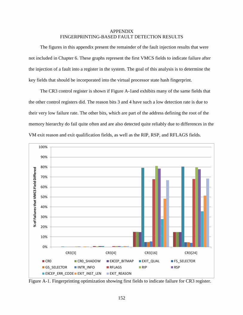
152
APPENDIX FINGERPRINTING-BASED FAULT DETECTION RESULTS
The figures in this appendix present the remainder of the fault injection results that were
not included in Chapter 6. These graphs represent the first VMCS fields to indicate failure after
the injection of a fault into a register in the system. The goal of this analysis is to determine the
key fields that should be incorporated into the virtual processor state hash fingerprint.
The CR3 control register is shown if Figure A-1and exhibits many of the same fields that
the other control registers did. The reason bits 3 and 4 have such a low detection rate is due to
their very low failure rate. The other bits, which are part of the address defining the root of the
memory hierarchy do fail quite often and are also detected quite reliably due to differences in the
VM exit reason and exit qualification fields, as well as the RIP, RSP, and RFLAGS fields.
0%
10%
20%
30%
40%
50%
60%
70%
80%
90%
100%
CR3[3] CR3[4] CR3[16] CR3[24]
% o
f Fai
lure
s th
at V
MCS
Fie
ld D
iffe
red
CR0 CR0_SHADOW EXCEP_BITMAP EXIT_QUAL FS_SELECTOR
GS_SELECTOR INTR_INFO RFLAGS RIP RSP
EXCEP_ERR_CODE EXIT_INST_LEN EXIT_REASON
Figure A-1. Fingerprinting optimization showing first fields to indicate failure for CR3 register.
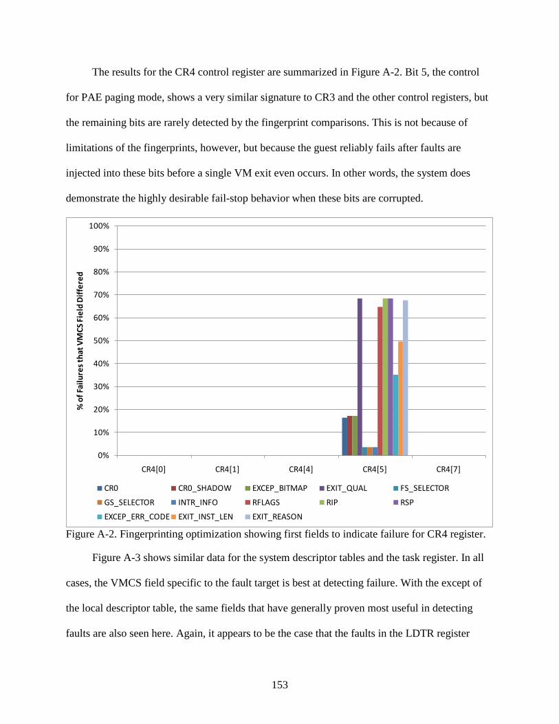
153
The results for the CR4 control register are summarized in Figure A-2. Bit 5, the control
for PAE paging mode, shows a very similar signature to CR3 and the other control registers, but
the remaining bits are rarely detected by the fingerprint comparisons. This is not because of
limitations of the fingerprints, however, but because the guest reliably fails after faults are
injected into these bits before a single VM exit even occurs. In other words, the system does
demonstrate the highly desirable fail-stop behavior when these bits are corrupted.
0%
10%
20%
30%
40%
50%
60%
70%
80%
90%
100%
CR4[0] CR4[1] CR4[4] CR4[5] CR4[7]
% o
f Fai
lure
s th
at V
MCS
Fie
ld D
iffe
red
CR0 CR0_SHADOW EXCEP_BITMAP EXIT_QUAL FS_SELECTOR
GS_SELECTOR INTR_INFO RFLAGS RIP RSP
EXCEP_ERR_CODE EXIT_INST_LEN EXIT_REASON
Figure A-2. Fingerprinting optimization showing first fields to indicate failure for CR4 register.
Figure A-3 shows similar data for the system descriptor tables and the task register. In all
cases, the VMCS field specific to the fault target is best at detecting failure. With the except of
the local descriptor table, the same fields that have generally proven most useful in detecting
faults are also seen here. Again, it appears to be the case that the faults in the LDTR register
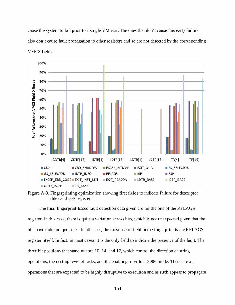
154
cause the system to fail prior to a single VM exit. The ones that don’t cause this early failure,
also don’t cause fault propagation to other registers and so are not detected by the corresponding
VMCS fields.
0%
10%
20%
30%
40%
50%
60%
70%
80%
90%
100%
GDTR[4] GDTR[16] IDTR[4] IDTR[16] LDTR[4] LDTR[16] TR[4] TR[16]
% o
f Fai
lure
s th
at V
MCS
Fie
ld D
iffe
red
CR0 CR0_SHADOW EXCEP_BITMAP EXIT_QUAL FS_SELECTOR
GS_SELECTOR INTR_INFO RFLAGS RIP RSP
EXCEP_ERR_CODE EXIT_INST_LEN EXIT_REASON LDTR_BASE IDTR_BASE
GDTR_BASE TR_BASE
Figure A-3. Fingerprinting optimization showing first fields to indicate failure for descriptor tables and task register.
The final fingerprint-based fault detection data given are for the bits of the RFLAGS
register. In this case, there is quite a variation across bits, which is not unexpected given that the
bits have quite unique roles. In all cases, the most useful field in the fingerprint is the RFLAGS
register, itself. In fact, in most cases, it is the only field to indicate the presence of the fault. The
three bit positions that stand out are 10, 14, and 17, which control the direction of string
operations, the nesting level of tasks, and the enabling of virtual-8086 mode. These are all
operations that are expected to be highly disruptive to execution and as such appear to propagate

155
errors to other registers. The reason for faults in many of the other bits, such as the carry flag or
parity flag, bits 0 and 2, respectively, to be rarely detected is not due to their tendency to crash
the system but instead because they are often overwritten by arithmetic operations that do no
cause VM exits. This is a limitation of the currently fingerprinting model since the resulting
arithmetic operations may result in SDC. One extension that is expected to reduce the probability
of such SDC is the inclusion of the general purpose registers in the VMCS, and consequently, in
the generation of the fingerprint.
0%
10%
20%
30%
40%
50%
60%
70%
80%
90%
100%
% o
f Fai
lure
s th
at V
MCS
Fie
ld D
iffe
red
CR0 CR0_SHADOW EXCEP_BITMAP EXIT_QUAL FS_SELECTOR
GS_SELECTOR INTR_INFO RFLAGS RIP RSP
EXCEP_ERR_CODE EXIT_INST_LEN EXIT_REASON
Figure A-4. Fingerprinting optimization showing first fields to indicate failure for RFLAGS register.
156
LIST OF REFERENCES
[1] K. Adams and O. Agesen, “A Comparison of Software and Hardware Techniques for x86 Virtualization,” in Proc. of the 12th
[2] N. Aggarwal, P. Ranganathan, N. P. Jouppi, and J. E. Smith, “Configurable Isolation: Building High Availability Systems with Commodity Multicore Processors,” in Proc. of the 33
Int. Conf. on Arch. Support for Programming Languages and Operating Systems, pp. 2-13, Oct. 2006.
rd
[3] J. Arlat, Y. Crouzet, J. Karlsson, P. Folkesson, E. Fuchs, and G. H. Leber, “Comparison of Physical and Software-implemented Fault Injection Techniques,” IEEE Trans. on Computers, vol. 52, no. 9, pp. 1115-1133, Sept. 2003.
Int. Symp. on Computer Architecture, pp. 470-481, June 2007.
[4] W. J. Armstrong, R. L. Arndt, D. C. Boutcher, R. G. Kovacs, D. Larson, K. A. Lucke, et. al., “Advanced Virtualization Capabilities of POWER5 Systems,” IBM Journal of Research and Development, vol. 49, no. 4, pp. 523-532, July 2005.
[5] T. M. Austin, “DIVA: A Reliable Substrate for Deep Submicron Microarchitecture Design,” in Proc. of the 32nd
[6] W. Bartlett and L. Spainhower, “Commercial Fault Tolerance: A Tale of Two Systems,” IEEE Trans. on Dependable and Secure Computing, vol. 1, no. 1, pp. 87-96, Jan 2004.
Int. Symp. on Microarchitecture, pp. 196-207, Nov. 1999.
[7] C. Basile, Z. Kalbarczyk, and R. K. Iyer, “Active Replication of Multithreaded Replicas,” IEEE Trans. on Parallel and Distributed Systems, vol. 17, no. 5, pp. 448-465, May 2006.
[8] R. C. Baumann, “Radiation-induced Soft Errors in Advanced Semiconductor Technologies,” IEEE Trans. on Device and Materials Reliability, vol. 5, no. 3, pp. 305-316, Sept. 2005.
[9] D. Bernick, B. Bruckert, P. D. Vigna, D. Garcia, R. Jardine, J. Klecka, and J. Smullen, “NonStop® Advanced Architecture,” in Proc. of the 35th
[10] D. Bertozzi and L. Benini, “Xpipes: A Network-on-chip Architecture for Gigascale Systems-on-chip,” IEEE Circuits and Systems Magazine, vol. 4, no. 2, pp. 18-31, Apr.-June, 2004.
Int. Conf. on Dependable Systems and Networks, June 2005.
[11] K. P. Birman and T. A. Joseph, “Exploiting Virtual Synchrony in Distributed Systems,” in Proc. of the 11th
[12] T. Bjerregaard and S. Mahadevan, “A Survey of Research and Practices of Network-on-chip,” ACM Computing Surveys, vol. 38, no. 1, pp. 1-51, Mar. 2006.
Symp. on Operating Systems Principles, pp. 123-138, Nov. 1987.
[13] S. Borkar, “Designing Reliable Systems from Unreliable Components: The Challenges of Transistor Variability and Degradation,” IEEE Micro, vol. 25, no. 6, pp. 10-16, Dec. 2005.

157
[14] S. Borkar et al., “Platform 2015: Intel Processor and Platform Evolution for the Next Decade,” Technology@Intel Magazine, pp. 1-10, March 2005.
[15] T. C. Bressoud, “TFT: A Software System for Application-transparent Fault Tolerance,” in Proc. of the 28th
[16] T. C. Bressoud and F. B. Schneider, “Hypervisor-based Fault-tolerance,” ACM Trans. on Computer Systems, vol. 14, no. 1, pp. 80-107, Feb. 1996.
Int. Conf. on Fault-Tolerant Computing, pp. 128-137, June 1998.
[17] G. Bronevetsky, D. Marques, and K. Pingali, “Application-level Checkpointing for Shared Memory Programs,” in Proc. of the 11th
[18] M. Butts, A. DeHon, and S. C. Goldstein, “Molecular Electronics: Devices, Systems and Tools for Gigagate, Gigabit Chips,” in Proc. IEEE/ACM Int. Conf. on Computer Aided Design, pp. 433-440, Nov. 2002.
Int. Conf. on Arch. Support for Programming Languages and Operating Systems, pp. 235-247, Oct. 2004.
[19] G. Candea, S. Kawamoto, Y. Fujiki, G. Friedman, and A. Fox, “Microreboot – A Technique for Cheap Recovery,” in Proc. of the 6th
[20] E. H. Cannon, D. D. Reinhardt, M. S. Gordon, and P. S. Makowenskyj, “SRAM SER in 90, 130, and 180nm Bulk and SOI Technologies,” in Proc. of the 42
Symp. on Operating System Design and Implementation, pp. 31-44, Dec. 2004.
nd
[21] M. Castro and B. Liskov, “Practical Byzantine Fault Tolerance,” in Proc. of the 3
Int. Reliability Physics Symp., pp. 300-304, April 2004.
rd
[22] M. Castro and B. Liskov, “Byzantine Fault Tolerance Can Be Fast,” in Proc. of the 31
Symp. on Operating System Design and Implementation, pp. 173-186, Feb. 1999.
st
[23] K. Chakraborty and P. Mazumder, Fault-tolerance and Reliability Techniques for High-density Random-access Memories. New Jersey: Prentice Hall, 2002, pp. 2-18.
Int. Conf. on Dependable Systems and Networks, pp. 513-518, July 2001.
[24] S. Chandra and P. M. Chen, “The Impact of Recovery Mechanisms on the Likelihood of Saving Corrupted State,” in Proc. of the 13th
[25] H. Chen, R. Chen, F. Zhang, B. Zang, and P. Yew, “Mercury: Combining Performance with Dependability using Self-virtualization,” in Proc. Int. Conf. on Parallel Processing, pp. 9, Sept. 2007.
Int. Symp. on Software Reliability Engineering, Nov. 2002.
[26] G. V. Chockler, I. Keidar, and R. Vitenberg, “Group Communication Specifications: A Comprehensive Study,” ACM Computing Surveys, vol. 33, no. 4, pp. 427-469, Dec. 2001.
[27] C. Clark, K. Fraser, S. Hand, J. G. Hansen, E. Jul, C. Limpach, et. al., “Live Migration of Virtual Machines,” in Proc. of the 2nd Symp. on Networked Systems Design and Implementation, pp. 273-286, July 2005.

158
[28] C. Constantinescu, “Trends and Challenges in VLSI Circuit Reliability,” IEEE Micro, vol. 23, no. 4, pp. 14-19, Aug. 2003.
[29] K. Constantinides et al., “BulletProof: A Defect-tolerant CMP Switch Architecture,” in Proc. of the 12th
[30] J. Cowling, D. Myers, B. Liskov, R. Rodrigues, and L. Shrira, “HQ Replication: A Hybrid Quorum Protocol for Byzantine Fault Tolerance,” in Proc. of the 7
Int. Symp. on High-Performance Computer Architecture, pp. 3-14, Feb. 2006.
th
[31] A. L. Cox, K. Mohanram, and S. Rixner, “Dependable ≠ Unaffordable,” in Proc. of the 1
Symp. on Operating System Design and Implementation, Nov. 2006.
st
[32] F. Cristian, H. Aghili, R. Strong, and D. Dolev, “Atomic Broadcast: From Simple Message Diffusion to Byzantine Agreement,” in Proc. of the 15
Workshop on Architectural and System Support for Improving Software Dependability, pp. 58-62, Oct. 2006.
th
[33] B. Cully, G. Lefebvre, D. Meyer, M. Feeley, N. Hutchinson, and A. Warfield, “Remus: High Availability via Asynchronous Virtual Machine Replication,” in Proc. of the 5
Int. Conf. on Fault-Tolerant Computing, pp. 200-206, June 1985.
th
[34] X. Défago, A. Schiper, and N. Sergent, “Semi-passive Replication,” in Proc. of the 17
USENIX Symp. On Networked Systems Design and Implementation, Apr. 2008.
th
[35] J. De Gelas, “Hardware Virtualization: The Nuts and Bolts,” Anandtech.com, page 9, Mar. 17, 2008. [Online]. Available: http://www.anandtech.com/printarticle.aspx?i=3263. [Accessed: Feb. 2, 2009].
Symp. on Reliable Distributed Systems, pp. 43-50, Oct. 1998.
[36] D. Dubie, “Virtualization Infiltrates Midsize Companies,” The New York Times, Nov. 19, 2008. Available http://www.nytimes.com.
[37] G. W. Dunlap, S. T. King, M. A. Basrai, and P. M. Chen, “ReVirt: Enabling Intrusion Analysis Through Virtual-machine Logging and Replay,” in Proc. of the 5th
[38] G. W. Dunlap, D. G. Lucchetti, P. M. Chen, and M. A. Fetterman, “Execution Replay for Multiprocessor Virtual Machines,” in Proc. of the Int. Conf. on Virtual Execution Environments, Mar. 2008.
Symp. on Operating System Design and Implementation, pp. 211-224, Dec. 2002.
[39] B. Fechner, J. Keller, and Peter Sobe, “Performance Estimation of Virtual Duplex Systems on Simultaneous Multithreaded Processors,” in Proc. of the 18th
[40] M. J. Fischer, N. A. Lynch, and M. S. Paterson, “Impossibility of Distributed Consensus with One Faulty Process,” Journal of the ACM, vol. 32, no. 2, pp. 374-382, April 1985.
Int. Symp. on Parallel and Distributed Processing, pp. 26-30, April 2004.
159
[41] K. Flautner, R. Uhlig, S. Reinhardt, and T. Mudge, “Thread-level Parallelism and Interactive Performance of Desktop Applications,” in Proc. of the 9th
[42] B. Ford, M. Hibler, J. Lepreau, P. Tullmann, G. Back, S. Goel, and S. Clawson, “Microkernels Meet Recursive Virtual Machine,” in Proc. of the 2
Int. Conf. on Architectural Support for Programming Languages and Operating Systems, pp. 129-138, Nov. 2000.
nd
[43] A. P. Frantz, F. L. Kastensmidt, L. Carro, and É. Cota, “Evaluation of SEU and Crosstalk Effects in Network-on-chip Switches,” in Proc. of the 19
Symp. on Operating System Design and Implementation, pp. 137-152, Oct. 1996.
th
[44] B. T. Gold, B. Falsafi, and J. C. Hoe, “Tolerating Processor Failures in a Distributed Shared-memory Multiprocessor,” Computer Arch. Lab at Carnegie Mellon, Tech. Rep. TR-2006-1, Aug. 2006.
Symp. on Integrated Circuits and Systems Design, pp. 202-207, Sept. 2006.
[45] B. T. Gold, J. Kim, J. C. Smolens, E. S. Chung, V. Liaskovitis, E. Nurvitadhi, et. al., “TRUSS: A Reliable, Scalable Server Architecture,” IEEE Micro, vol. 25, no. 6, pp. 51-58, Dec. 2005.
[46] R. P. Goldberg, “Survey of Virtual Machine Research,” IEEE Computer, pp. 34-45, June 1974.
[47] M. A. Gomaa, C. Scarbrough, T. N. Vijaykumar, and I. Pomeranz, “Transient-fault Recovery for Chip Multiprocessors,” IEEE Micro, vol. 23, no. 6, pp. 76-83, Nov. 2003.
[48] W. Gu, Z. Kalbarczyk, and R. K. Iyer, “Error Sensitivity of the Linux kernel Executing on PowerPC G4 and Pentium 4 Processors,” in Proc. of the 34th
[49] R. Guerraoui and A. Schiper, “Software-based Replication for Fault Tolerance,” IEEE Computer, pp. 68-74, Apr. 1997.
Int. Conf. on Dependable Systems and Networks, July 2004.
[50] N. Hayashibara, P. Urbán, and A. Schiper, “Performance Comparison Between the Paxos and Chandra-Toueg Consensus Algorithms,” in Proc. of the Int. Arab Conf. on Information Technology, pp. 526-533, Dec. 2002.
[51] T. Heijmen, P. Roche, G. Gasiot, K. R. Forbes, and D. Giot, “A Comprehensive Study on the Soft-error Rate of Flip-flops from 90nm Production Libraries,” IEEE Trans. on Device and Materials Reliability, vol. 7, no. 1, pp. 84-95, Mar. 2007.
[52] M. P. Herlihy and J. M. Wing, “Linearizability: A Correctness Condition for Concurrent Objects,” ACM Trans. On Programming Languages and Systems, vol. 12, no. 3, pp. 463-492, July 1990.
[53] Hewlett-Packard, “HP NonStop Servers and Open Standards,” available at www.hp.com, May 2005.

160
[54] D. R. Hower and M. D. Hill, “Rerun: Exploiting Episodes for Lightweight Memory Race Recording,” in Proc. of the 34th
[55] L. Huang and Q. Xu, “On Modeling the Lifetime Reliability of Homogeneous Many-core Systems,” in Proc. of the 14
Int. Symp. on Computer Architecture, pp. 265-276, June 2008.
th
[56] IBM, “Dynamic Logical Partitioning in IBM eServer pSeries,” white paper, Oct. 2002.
IEEE Pacific Rim Int. Symp. on Dependable Computing, pp. 87-94, Dec. 2008.
[57] Intel Corporation, Intel 64 and IA-32 Architectures Software Developer’s Manual, vol. 3B, Nov. 2008.
[58] Intel Corporation, “Intel®
[59] Intel Corporation, “Reliability, Availability, and Serviceability for the Always-on Enterprise,” white paper, Aug. 2005.
X18-M/X25-M SATA Solid State Drive,” SSDSA1MH080G1 datasheet, Jan. 2009.
[60] International Technology Roadmap for Semiconductors, 2007 ed. Austin, TX: Semiconductor Industry Association, International SEMATECH, 2007.
[61] C. M. Jeffery and R. J. O. Figueiredo, “Hierarchical Fault Tolerance for Nanoscale Memories,” IEEE Trans. on Nanotechnology, vol. 5, no. 4, pp. 407-414, July 2006.
[62] C. M. Jeffery and R. J. O. Figueiredo, “Reducing Fault Detection Latencies in Virtually-lockstepped Systems,” in Proc. of the IEEE 3rd
[63] C. M. Jeffery and R. J. O. Figueiredo, “Towards Byzantine Fault Tolerance in Many-core Computing Platforms,” in Proc. of the 13
Workshop on Dependable Architectures, Nov. 2008.
th
[64] R. Jiménez-Peris and S. Arévalo, “Deterministic Scheduling for Transactional Multithreaded Replicas,” in Proc. of the 19
Pacific Rim Int. Symp. On Dependable Computing, Dec. 2007.
th
[65] G. A. Kanawati, N. A. Kanawati, and J. A. Abraham, “FERRARI: A Flexible Software-based Fault and Error Injection System,” IEEE Trans. on Computers, vol. 44, no. 2, pp. 248-260, Feb. 1995.
Symp. on Reliable Distributed Systems, pp. 164-173, Oct. 2000.
[66] A. Kejariwal, X. Tian, W. Li, M. Girkar, S. Kozhukhov, H. Saito, et. al., “On the Performance Potential of Different Types of Speculative Thread-level Parallelism,” in Proc. of the 20th
[67] K. P. Kihlstrom, L. E. Moser, and P. M. Melliar-Smith, “The SecureRing Protocols for Securing Group Communication,” in Proc. of the 31
Int. Conf. on Supercomputing, pp. 24-36, June 2006.
st Hawaii Int. Conf. on System Sciences, pp. 317-326, Jan. 1998.

161
[68] A. Kivity, Y. Kamay, D. Laor, U. Lublin, and A. Liguori, “kvm: The Linux Virtual Machine Monitor,” in Proc. of the 9th
[69] K. Kourai and S. Chiba, “A Fast Rejuvenation Technique for Server Consolidation with Virtual Machines,” in Proc. of the 37
Ottawa Linux Symp., June 2007.
th
[70] A. L. Lacaita, “Phase Change Memories: State-of-the-art, Challenges and Perspectives,” Solid State Electronics, vol. 50, no. 1, pp. 24-31, Jan. 2006.
Int. Conf. on Dependable Systems and Networks, pp. 245-255, June 2007.
[71] L. Lamport and M. Massa, “Cheap Paxos,” in Proc. of the 34th
[72] M. Larabel, “Phoronix Test Suite Released,” April 2, 2008. [Online]. Available: http://www.phoronix.com/scan.php?page=article&item=pts_080 [Accessed: Mar 2, 2009].
Int. Conf. on Dependable Systems and Networks, pp. 307-314, June 2004.
[73] M. Le, A. Gallagher, and Y. Tamir, “Challenges and Opportunities with Fault Injection in Virtualized Systems,” in Proc. of the 1st
[74] J. LeVasseur, V. Uhlig, M. Chapman, P. Chubb, B. Leslie, and G. Heiser, “Pre-virtualization: Soft Layering for Virtual Machines,” tech. report TR-2006-15, Fakultät für Informatik, Universität Karlsruhe, July 2006.
Int. Workshop on Virtualization Performance: Analysis, Characterization, and Tools, Apr. 2008.
[75] M. Li, P. Ramachandran, S. K. Sahoo, S. V. Adve, V. S. Adve, and Y. Zhou, “Understanding the Propagation of Hard Errors to Software and Implications for Resilient System Design,” in Proc. of the 13th
[76] R. Libeskind-Hadas and E. Brandt, “Origin-based Fault-tolerant Routing in the Mesh,” in Proc. of the 1
Int. Conf. on Arch. Support for Programming Languages and Operating Systems, Mar. 2008.
st
[77] J. Lu, A. Das, W. Hsu, K. Nguyen, and S. G. Abraham, “Dynamic Helper Threaded Prefetching on the Sun UltraSPARC CMP Processor,” in Proc. of the 38
Int. Symp. on High Performance Computer Architectures, pp. 102-111, Jan. 1995.
th
[78] D. Lucchetti, S. K. Reinhardt, and P. M. Chen, “ExtraVirt: Detecting and Recovering from Transient Processor Faults,” in Proc. of the 20
Int. Symp. on Microarchitecture, pp. 93-104, Nov. 2005.
th
[79] Q. Ma, W. Li, I. Yen, F. Bastani, and I. Chen, “Survivable Systems Based on an Adaptive NMR Algorithm,” in Proc. of the 18
Symp. on Operating Systems Principles, pp. 1-8, Oct. 2005.
th Int. Parallel and Distributed Processing Symp., pp. 68-77, Apr. 2004.

162
[80] A. Mahmood and E. J. McClusky, “Concurrent Error Detection using Watchdog Processors—A Survey,” IEEE Trans. on Computers, vol. 37, no. 2, pp. 160-174, Feb. 1988.
[81] J.-P. Martin and L. Alvisi, “Fast Byzantine Consensus,” in Proc. IEEE Trans. on Dependable and Secure Computing, vol. 3, no. 3, pp. 202-215, Sept. 2006.
[82] C. McNairy and R. Bhatia, “Montecito: A Dual-core, Dual-threaded Itanium Processor,” IEEE Micro, vol. 25, no. 2, pp. 10-20, Apr. 2005.
[83] S. S. Mukherjee, M. Kontz, and S. K. Reinhardt, “Detailed Design and Evaluation of Redundant Multithreading Alternatives,” in Proc. of the 29th
[84] J. Nakano, P. Montesinos, K. Gharachorloo, and J. Torrellas, “ReViveI/O: Efficient Handling of I/O in Highly-available Rollback-recovery Servers,” in Proc. of the 12
Int. Symp. On Computer Architecture, May 2002.
th
[85] N. Nakka, K. Pattabiraman, and R. Iyer, “Processor-level Selective Replication,” in Proc. of the 37
Int. Symp. on High-Performance Computer Architecture, pp. 200-211, Feb. 2006.
th
[86] M. Nelson, B. Lim, and G. Hutchins, “Fast Transparent Migration for Virtual Machines,” in Proc.of USENIX, pp. 391-394, Apr. 2005.
Int. Conf. on Dependable Systems and Networks, pp. 544-553, June 2007.
[87] N. Oh, P. P. Shirvani, and E. J. McCluskey, “Error Detection by Duplicated Instructions in Super-scalar Processors,” IEEE Trans. On Reliability, vol. 51, no. 1, March 2002.
[88] N. Oh, P. P. Shirvani, and E. J. McCluskey, “Control-flow Checking by Software Signatures,” IEEE Trans. On Reliability, vol. 51, no. 2, March 2002.
[89] A. Parashar, S. Gurumurthi, and A. Sivasubramaniam, “A Complexity-effective Approach to ALU Bandwidth Enhancement for Instruction-level Temporal Redundancy,” in Proc. of the 31st
[90] D. Park, C. Nicopoulos, J. Kim, N. Vijaykrishnan, and C. R. Das, “Exploring Fault-tolerant Network-on-chip Architectures,” in Proc. of the 36
Int. Symp. on Computer Architecture, pp. 376-386, June 2004.
th
[91] S. Potyra, V. Sieh, and M. D. Cin, “Evaluating Fault-tolerant Systems Designs using FAUmachine,” in Proc. of the 2
Int. Conf. on Dependable Systems and Networks, pp. 93-104, June 2006.
nd
[92] M. Prvulovic, Z. Zhang, and J. Torrellas, “ReVive: Cost-effective Architectural Support for Rollback Recovery in Shared-memory Multiprocessors,” in Proc. of the 29
Workshop on Engineering Fault Tolerant Systems, Sept. 2007.
th
[93] R. M. Ramanathan, “Intel Multi-core Processors: Making the Move to Quad-core and Beyond,” white paper, Intel Corp., Sept. 2006.
Int. Symp. on Computer Architecture, pp. 111-122, May 2002.

163
[94] G. A. Reis, J. Chang, D. I. August, R. Cohn, and S. S. Mukherjee, “Configurable Transient Fault Detection via Dynamic Binary Translation,” in Proc. of the 2nd
[95] G. A. Reis, J. Chang, N. Vachharajani, R. Rangan, and D. I. August, “SWIFT: Software Implemented Fault Tolerance,” in Proc. of the Int. Symp. Code Generation and Optimization, pp. 243-254, March 2005.
Workshop on Architectural Reliability, Nov. 2006.
[96] H. P. Reiser, F. J. Hauck, R. Kapitza, and W. Schröder-Preikschat, “Hypervisor-based Redundant Execution on a Single Physical Host,” in Proc. of the 6th
[97] H. P. Reiser and R. Kapitza, “Hypervisor-based Efficient Proactive Recovery,” in Proc. of the 26
European Dependable Computing Conf., supplemental volume, pp. 67-68, Oct. 2006.
th
[98] M. Rosenblum and T. Garfinkel, “Virtual machine monitors: current technology and future trends,” IEEE Computer, vol. 38, no. 5, pp. 39-47, May 2005.
IEEE Symp. On Reliable Distributed Systems, Oct. 2007.
[99] E. Rotenberg, “AR-SMT: A Microarchitectural Approach to Fault Tolerance in Microprocessors,” in Proc. of the 29th
[100] G. P. Saggese, A. Vetteth, Z. Kalbarczyk, and R. Iyer, “Microprocessor Sensitivity to Failures: Control vs. Execution and Combinational vs. Sequential Logic,” in Proc. of the 35
Int. Symp. on Fault-Tolerant Computing, pp. 84-91, June 1999.
th
[101] N. R. Saxena and E. J. McCluskey, “Control-flow Checking using Watchdog Assists and Extended-precision Checksums,” IEEE Trans. on Computers, vol. 39, no. 4, pp. 554-559, Apr. 1990.
Int. Conf. on Dependable Systems and Networks, June 2005.
[102] D. Scales, “Fault Tolerant VMs in VMware Infrastructure: Operation and Best Practices,” presented at VMworld conference, Sept. 2008.
[103] A. Schiper, “Early Consensus in an Asynchronous System with a Weak Failure Detector,” Distributed Computing, vol. 10, no. 3, pp. 149-157, Mar. 1997.
[104] F. B. Schneider, “Implementing Fault-tolerant Services using the State Machine Approach: A Tutorial,” ACM Computing Surveys, vol. 22, no. 4, pp. 299-319, Dec. 1990.
[105] R. Sedgewick, Algorithms in C. Boston, MA: Addison-Wesley, 1997.
[106] P. Shivakumar, M. Kistler, S. W. Keckler, D. Burger, and L. Alvisi, “Modeling the Effect of Technology Trends on the Soft Error Rate of Combinational Logic,” in Proc. of the 32nd
[107] A. Shye, T. Moseley, V. J. Reddi, J. Blomstedt, and D. A. Connors, “Using Process-level Redundancy to Exploit Multiple cores for Transient Fault Tolerance,” in Proc. of the 37
Int. Conf. on Dependable Systems and Networks, pp. 389-398, May 2002.
th Int. Conf. on Dependable Systems and Networks, June 2007.

164
[108] J. C. Smolens, B. T. Gold, J. C. Hoe, B. Falsafi, and K. Mai, “Detecting Emerging Wearout Faults,” in Proc. of the IEEE Workshop on Silicon Errors in Logic – System Effects, April 2007.
[109] J. C. Smolens, B. T. Gold, B. Falsafi, and J. C. Hoe, “Reunion: Complexity-effective Multicore Redundancy,” in Proc. of the 39th
[110] J. C. Smolens, B. T. Gold, J. Kim, B. Falsafi, J. C. Hoe, and A. G. Nowatzyk, “Fingerprinting: Bounding Soft-error Detection Latency and Bandwidth,” IEEE Micro, vol. 24, no. 6, pp. 22-29, Nov. 2004.
Int. Symp. on Microarchitecture, pp. 223-234, Dec. 2006.
[111] D. J. Sorin, M. K. Martin, M. D. Hill, and D. A. Wood, “SafetyNet: Improving the Availability of Shared Memory Multiprocessors with Global Checkpoint/Recovery,” in Proc. of the 29th
[112] L. Spainhower and T. A. Gregg, “IBM S/390 Parallel Enterprise server G5 Fault Tolerance: A Historical Perspective,” IBM Journal of Research and Development, vol. 43, no. 5, pp 863-873, Sept. 1999.
Int. Symp. on Computer Architecture, pp. 123-134, May 2002.
[113] L. Spracklen and S. G. Abraham, “Chip Multithreading – Opportunities and Challenges,” in Proc. of the 11th
[114] J. Srinivasan, S. V. Adve, P. Bose, and J. A. Rivers, “The Impact of Technology Scaling on Lifetime Reliability,” in Proc. of the 34
Int. Symp. on High-Performance Computer Architecture, pp. 248-252, Feb. 2005.
th
[115] S. Srinivasan, S. Kandula, C. Andrews, and Y. Zhou, “Flashback: A Lightweight Extension for Rollback and Deterministic Replay for Software Debugging,” in Proc. of the USENIX Technical Conference, pp. 29-44, June 2004.
Int. Conf. on Dependable Systems and Networks, pp. 177-186, July 2004.
[116] Stratus, “Benefit from Stratus Continuous Processing Technology,” white paper, July 2007.
[117] Stratus, “Stratus Continuum Series VOS, Stratus Virtual Operating System,” available at www.stratus.com, 2003.
[118] A. W. Topol, D. C. La Tulipe Jr., L. Shi, D. J. Frank, K. Bernstein, S. E. Steen, et. al., “Three-dimensional Integrated Circuits,” IBM Journal of Research and Development, vol. 50, no. 5, pp. 491-506, July 2006.
[119] S. Vangal et al., “An 80-tile 1.28TFLOPS Network-on-chip in 65nm CMOS,” in Proc. of the Int. Solid State Circuits Conf., pp. 5-7, Feb. 2007.
[120] VMware, “A Performance Study of Hypervisors,” white paper, Feb. 2007.
165
[121] L. Wang, Z. Kalbarczyk, W. Gu, and R. K. Iyer, “An OS-level Framework for Providing Application-aware Reliability,” in Proc. of the 12th
[122] N. J. Wang and S. J. Patel, “ReStore: Symptom-based Soft error Detection in Microprocessors,” IEEE Transactions on Dependable and Secure Computing, vol. 3, no. 3, pp. 188-201, Sept. 2006.
Pacific Rim Int. Symp. on Dependable Computing, pp. 55-62, Dec. 2006.
[123] N. J. Wang, A. Mahesri, and S. J. Patel, “Examining ACE Analysis Reliability Estimates using Fault Injection,” in Proc. of the 34th
[124] C. Weaver and T. Austin, “A Fault Tolerant Approach to Microprocessor Design,” in Proc. of the 31
Int. Symp. on Computer Architecture, pp. 460-469, June 2007.
st
[125] S. Webber and J. Beirne, “The Stratus Architecture,” in Proc. of the 21
Int. Conf. on Dependable Systems and Networks, pp. 411-420, July 2001.
st
[126] P. M. Wells, K. Chakraborty, and G. S. Sohi, “Adapting to Intermittent Faults in Multicore Systems,” in Proc. of the 13
Int. Symp. on Fault-Tolerant Computing, June 1991.
th
[127] A. Whitaker, R. S. Cox, M. Shaw, and S. D. Gribble, “Rethinking the Design of Virtual Machine Monitors,” IEEE Computer, vol. 38, no. 5, pp. 57-62, May 2005.
Int. Conf. on Architectural Support for Programming Languages and Operating Systems, pp. 255-264, Mar. 2008.
[128] M. Xu, R. Bodik, and M. D. Hill, “A ‘Flight Data Recorder’ for Enabling Full-system Multiprocessor Deterministic Replay,” in Proc. of the 30th
[129] M. Xu, V. Malyugin, J. Sheldon, G. Venkitachalam, and B. Weissman, “ReTrace: Collecting Execution Trace with Virtual Machine Deterministic Replay,” in Proc. Workshop on Modeling, Benchmarking and Simulation, June 2007.
Int. Symp. on Computer Architecture, pp. 122-133, June 2003.
[130] J. F. Ziegler et al., “IBM Experiments in Soft Fails in Computer Electronics (1978-1994),” IBM J. Res. Develop., vol. 40, no. 1, pp. 3-17, Jan. 1996.

166
BIOGRAPHICAL SKETCH
Casey Jeffery was born and raised in the Black Hills region of South Dakota. He
completed his B.S. degree in computer engineering at the South Dakota School of Mines and
Technology in Rapid City. During his sophomore year, he took a semester off to intern at Intel
Corporation. This internship was very successful and prompted him to continue interning at
various Intel groups and plant sites throughout the U.S. every year since.
After graduation in 2002, he moved to Gainesville to attend the University of Florida and
began work on a M.S. degree in computer engineering in the Department of Electrical and
Computer Engineering. After a year of general studies, he joined the ACIS lab and worked with
Prof. Renato Figueiredo on research geared towards improving fault tolerance in nanoscale
memory devices. He then continued to work in the ACIS lab for the Ph.D. program starting in
2005, but switched his focus from nanoscale memory technology to virtualization technology.
The following year he was fortunate enough to land an internship with the creators of
Intel®
Virtualization Technology, the Core Virtualization Research (CVR) group in Hillsboro,
OR. He completed two internships with the group before joining as a full-time research scientist
in early 2008.