i c bus monitor plus software development kit for windows ... · pdf filefor the latest...
TRANSCRIPT
Programmer’s Guide
I2C Bus Monitor PlusSoftware Development Kit
for Windows
MS Visual C++ Edition
Version 1
www.mcc-us.com

NOTE
For the latest information on this product, seeReadme.TXT document file.
This document defines the Application Program Interface (API) for MCC’s I2C Bus Monitor Plus SoftwareDevelopment Kit Version 1 for 32-bit Windows operating systems.
Copyright 2003, Micro Computer Control Corporation. All rights reserved.

Table of Contents
Introduction . . . . . . . . . . . . . . . . . . . . . . . . . . . . . . . . . . . . . . . . . . . . . . . . . . . . . . . . . . . . . . . . . . . . . . . . . . . . . . . . . . 1
Features . . . . . . . . . . . . . . . . . . . . . . . . . . . . . . . . . . . . . . . . . . . . . . . . . . . . . . . . . . . . . . . . . . . . . . . . . . . . . . . . . . . . . 1
The Software Development Kit . . . . . . . . . . . . . . . . . . . . . . . . . . . . . . . . . . . . . . . . . . . . . . . . . . . . . . . . . . . . . . . . . . . 2Driver . . . . . . . . . . . . . . . . . . . . . . . . . . . . . . . . . . . . . . . . . . . . . . . . . . . . . . . . . . . . . . . . . . . . . . . . . . . . . . . . . 2Parser . . . . . . . . . . . . . . . . . . . . . . . . . . . . . . . . . . . . . . . . . . . . . . . . . . . . . . . . . . . . . . . . . . . . . . . . . . . . . . . . . 2Sample Applications . . . . . . . . . . . . . . . . . . . . . . . . . . . . . . . . . . . . . . . . . . . . . . . . . . . . . . . . . . . . . . . . . . . . . 2
Monitoring and Analysis System Components . . . . . . . . . . . . . . . . . . . . . . . . . . . . . . . . . . . . . . . . . . . . . . . . . . . . . . . 2The iBMP SDK Driver Architecture . . . . . . . . . . . . . . . . . . . . . . . . . . . . . . . . . . . . . . . . . . . . . . . . . . . . . . . . . 3iBMP Pod . . . . . . . . . . . . . . . . . . . . . . . . . . . . . . . . . . . . . . . . . . . . . . . . . . . . . . . . . . . . . . . . . . . . . . . . . . . . . . 3iBMP Interface Card . . . . . . . . . . . . . . . . . . . . . . . . . . . . . . . . . . . . . . . . . . . . . . . . . . . . . . . . . . . . . . . . . . . . . 3iBMP Interface Card Driver . . . . . . . . . . . . . . . . . . . . . . . . . . . . . . . . . . . . . . . . . . . . . . . . . . . . . . . . . . . . . . . . 3iBMP DLL (Dynamic Linked Library) . . . . . . . . . . . . . . . . . . . . . . . . . . . . . . . . . . . . . . . . . . . . . . . . . . . . . . . 3Application Layer . . . . . . . . . . . . . . . . . . . . . . . . . . . . . . . . . . . . . . . . . . . . . . . . . . . . . . . . . . . . . . . . . . . . . . . . 4
System Requirements . . . . . . . . . . . . . . . . . . . . . . . . . . . . . . . . . . . . . . . . . . . . . . . . . . . . . . . . . . . . . . . . . . . . . . . . . . . 4
Installation . . . . . . . . . . . . . . . . . . . . . . . . . . . . . . . . . . . . . . . . . . . . . . . . . . . . . . . . . . . . . . . . . . . . . . . . . . . . . . . . . . . 4Drivers (DLL) . . . . . . . . . . . . . . . . . . . . . . . . . . . . . . . . . . . . . . . . . . . . . . . . . . . . . . . . . . . . . . . . . . . . . . . . . . 4iBMP Pod Configuration File . . . . . . . . . . . . . . . . . . . . . . . . . . . . . . . . . . . . . . . . . . . . . . . . . . . . . . . . . . . . . . 4Sample Applications . . . . . . . . . . . . . . . . . . . . . . . . . . . . . . . . . . . . . . . . . . . . . . . . . . . . . . . . . . . . . . . . . . . . . 4
Application Development . . . . . . . . . . . . . . . . . . . . . . . . . . . . . . . . . . . . . . . . . . . . . . . . . . . . . . . . . . . . . . . . . . . . . . . 5
Application Development - Visual C++ . . . . . . . . . . . . . . . . . . . . . . . . . . . . . . . . . . . . . . . . . . . . . . . . . . . . . . . . . . . . 5
Dynamic Linked Library (DLL) Programming . . . . . . . . . . . . . . . . . . . . . . . . . . . . . . . . . . . . . . . . . . . . . . . . . . . . . . . 5
Phase 1, Establishing Communications . . . . . . . . . . . . . . . . . . . . . . . . . . . . . . . . . . . . . . . . . . . . . . . . . . . . . . . . . . . . . 6Teaching MSVC about the iBMP DLL . . . . . . . . . . . . . . . . . . . . . . . . . . . . . . . . . . . . . . . . . . . . . . . . . . . . . . . 6Adding buttons, and edit box controls . . . . . . . . . . . . . . . . . . . . . . . . . . . . . . . . . . . . . . . . . . . . . . . . . . . . . . . . 7Adding a member variable . . . . . . . . . . . . . . . . . . . . . . . . . . . . . . . . . . . . . . . . . . . . . . . . . . . . . . . . . . . . . . . . . 8Adding member functions . . . . . . . . . . . . . . . . . . . . . . . . . . . . . . . . . . . . . . . . . . . . . . . . . . . . . . . . . . . . . . . . . 9Adding message handlers for button clicks . . . . . . . . . . . . . . . . . . . . . . . . . . . . . . . . . . . . . . . . . . . . . . . . . . . . 9Displaying pod data . . . . . . . . . . . . . . . . . . . . . . . . . . . . . . . . . . . . . . . . . . . . . . . . . . . . . . . . . . . . . . . . . . . . . 10Testing pod communications . . . . . . . . . . . . . . . . . . . . . . . . . . . . . . . . . . . . . . . . . . . . . . . . . . . . . . . . . . . . . . 11
Phase 2, Displaying pod data in a more meaningful way . . . . . . . . . . . . . . . . . . . . . . . . . . . . . . . . . . . . . . . . . . . . . . 12Parsing the pod data packet stream . . . . . . . . . . . . . . . . . . . . . . . . . . . . . . . . . . . . . . . . . . . . . . . . . . . . . . . . . 14Testing default parser output . . . . . . . . . . . . . . . . . . . . . . . . . . . . . . . . . . . . . . . . . . . . . . . . . . . . . . . . . . . . . . 16
Phase 3, Customizing parser output . . . . . . . . . . . . . . . . . . . . . . . . . . . . . . . . . . . . . . . . . . . . . . . . . . . . . . . . . . . . . . . 16Testing display control options . . . . . . . . . . . . . . . . . . . . . . . . . . . . . . . . . . . . . . . . . . . . . . . . . . . . . . . . . . . . 17
Phase 4, Expanding control of the iBMP pod . . . . . . . . . . . . . . . . . . . . . . . . . . . . . . . . . . . . . . . . . . . . . . . . . . . . . . . 18Add code to support the expanded controls . . . . . . . . . . . . . . . . . . . . . . . . . . . . . . . . . . . . . . . . . . . . . . . . . . . 19Testing parser control options . . . . . . . . . . . . . . . . . . . . . . . . . . . . . . . . . . . . . . . . . . . . . . . . . . . . . . . . . . . . . 21

Phase 5, Adding user controls . . . . . . . . . . . . . . . . . . . . . . . . . . . . . . . . . . . . . . . . . . . . . . . . . . . . . . . . . . . . . . . . . . . 22
Appendix A. iBMP DLL Application Interface Descriptions . . . . . . . . . . . . . . . . . . . . . . . . . . . . . . . . . . . . . . . . . . . 23BmpDllVer() - Get I2C iBMP DLL Revision . . . . . . . . . . . . . . . . . . . . . . . . . . . . . . . . . . . . . . . . . . . . . . . . . 23BmpQuickTrace() - Quick Trace . . . . . . . . . . . . . . . . . . . . . . . . . . . . . . . . . . . . . . . . . . . . . . . . . . . . . . . . . . 23BmpCheckBoardNumber() - Check I2C iBMP Interface Board Number . . . . . . . . . . . . . . . . . . . . . . . . . . . 24BmpInitPod() - Initialize iBMP Pod . . . . . . . . . . . . . . . . . . . . . . . . . . . . . . . . . . . . . . . . . . . . . . . . . . . . . . . . 25BmpTraceStart() - Trace Start . . . . . . . . . . . . . . . . . . . . . . . . . . . . . . . . . . . . . . . . . . . . . . . . . . . . . . . . . . . . . 25BmpReadPacket() - Read iBMP Pod Packet . . . . . . . . . . . . . . . . . . . . . . . . . . . . . . . . . . . . . . . . . . . . . . . . . . 28BmpTraceStop() - Trace Stop . . . . . . . . . . . . . . . . . . . . . . . . . . . . . . . . . . . . . . . . . . . . . . . . . . . . . . . . . . . . . 31BmpShutdown() - iBMP Pod Shutdown . . . . . . . . . . . . . . . . . . . . . . . . . . . . . . . . . . . . . . . . . . . . . . . . . . . . . 32
1
Introduction
The I2C Bus Monitor Plus
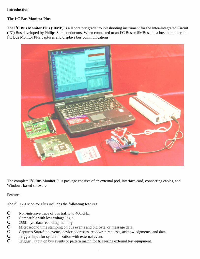
The I2C Bus Monitor Plus (iBMP) is a laboratory grade troubleshooting instrument for the Inter-Integrated Circuit(I2C) Bus developed by Philips Semiconductors. When connected to an I2C Bus or SMBus and a host computer, theI2C Bus Monitor Plus captures and displays bus communications.
The complete I2C Bus Monitor Plus package consists of an external pod, interface card, connecting cables, andWindows based software.
Features
The I2C Bus Monitor Plus includes the following features:
C Non-intrusive trace of bus traffic to 400KHz.C Compatible with low voltage logic.C 256K byte data recording memory.C Microsecond time stamping on bus events and bit, byte, or message data.C Captures Start/Stop events, device addresses, read/write requests, acknowledgments, and data.C Trigger Input for synchronization with external event.C Trigger Output on bus events or pattern match for triggering external test equipment.

2
The Software Development Kit
The MS VC++ I2C Bus Monitor Plus Software Development Kit (iBMP SDK) supports the development of custom32-bit Windows application software. This kit enables Microsoft Visual C++ software developers and test engineers tointegrate the extensive data collection capabilities of the I2C Bus Monitor Plus (#MIIC-102) into custom real-time dataanalysis and test applications.
The iBMP SDK is designed to make it easy to develop custom monitoring, analysis, and test applications for I2C Busand SMBus based systems. To accomplish this, the iBMP SDK provides three key ingredients; driver, parser, andsample applications.
1. Driver
A driver is a software component that allows a custom application to control the real-time data collection features ofthe I2C Bus Monitor Plus pod, and provides a method of reading pod data packets generated by bus message traffic.
iBMP SDK V1 includes a DLL based driver for conventional code-based programming.
2. Parser
A parser is a software component that accepts a stream of pod generated data packets, interprets the meaning of thepackets, identifies, filters, and highlights specific bus activity of interest, and translates bus activity into a meaningfulrepresentation for presentation to an application user.
iBMP SDK V1 includes an I2C Bus ASCII-Hex parser in source code form, suitable for the creation of custom parsers.
3. Sample Applications
Sample applications show how to use the driver and parser included in the kit, and provide the basis for creatingcustomized applications.
The iBMP SDK includes sample application programs in Microsoft’s Visual C++. These sample programs include thesource code for controlling the I2C Bus Pod and analyzing bus message data and time-stamp information, and providean excellent framework for the developer or test engineer constructing custom I2C Bus or SMBus test or analysisapplications.
Monitoring and Analysis System Components
An I2C Bus and/or SMBus monitoring and analysis system based upon the iBMP SDK consists of five majorcomponents. These include:

3
The iBMP SDK Driver Architecture
The iBMP SDK drivers use a layered architecture. Each layer derives much of its functionality from lower layers. Thislayered architecture includes:
Application Layer
iBMP DLL (Dynamic Linked Library)
iBMP Interface Card Driver
iBMP Interface Card
iBMP Pod
iBMP Pod
In this architecture, the iBMP Pod is the lowest layer, and provides a physical connection to the I2C Bus and/or SMBusin the system under test. The components in the pod allow it to capture, timestamp, store, and upload bus activity.
The iBMP Pod is included with the I2C Bus Monitor Plus (#MIIC-102).
iBMP Interface Card
The iBMP Interface Card provides a physical connection between the system’s host computer and the pod. PCI, ISA,and PC Card versions of the interface card are currently supported.
The iBMP Interface Card is included with the I2C Bus Monitor Plus (#MIIC-102).
iBMP Interface Card Driver
The iBMP Interface Card Driver provides software access to the interface card and its attached pod.
The iBMP Interface Card Driver is included with the I2C Bus Monitor Plus (#MIIC-102).
iBMP DLL (Dynamic Linked Library)
The iBMP DLL (Dynamic Linked Library) provides low level access to the iBMP pod’s features and functions. Thislayer supports an Application Program Interface (API) that can be accesses from conventional code-basedprogramming applications.
The iBMP DLL is included with the iBMP SDK.

4
Application Layer
The Application is a user developed software component customized to meet the needs of the user. An application willinitialize and control the iBMP pod, and may contain a parser to analyze the stream of pod data, and identify busactivity of interest. A parser can be built into the application source code, or it can be an add-on component.
The iBMP SDK includes an application source code examples that demonstrate how to use the iBMP DLL along withan I2C Bus ASCII Hex parser that can be use as the basis for creating a custom application.
The iBMP DLL API and sample application programs that use this interface can be found in later sections of thisguide.
System Requirements
To use the iBMP SDK, your PC must meet the following requirements:
MCC I2C Bus Monitor Plus (#MIIC-102) ISA, PCI, or PC Card versionMicrosoft Windows (95, 98, ME, NT 4.0, 2000, XP)Microsoft Visual C++ Version 6 or above.
Installation
An installation program is provided on the distribution disk which will allow you to install the iBMP SDK. TO run theinstallation, insert the diskette or CD into your drive. If the installation program does not start automatically, youshould start Windows Explorer and navigate to the root folder on the diskette or CDROM, and double-click on theSETUP.EXE program file to start the installation.
The iBMP SDK installation supports the installation of the following components:
Drivers (DLL)
iBMP32100.DLLiBMP32Key.DLL
iBMP Pod Configuration File
BMPlus.POD
Sample Applications
Phase 1, Establishing communications.Phase 2. Displaying pod data.Phase 3, Customizing output.Phase 4, Expanding control.Phase 5, Adding user controls.
See Packlist.TXT for components installation information.
5
Application Development
This guide uses a step-by-step approach to application program development. From starting a new project, throughadding simple capabilities, to creating a robust application. The sample applications cover all aspects of bus datacollection and display.
You may find that your specific test requirements do not require all of the flexibility incorporated into our samples.Reducing program flexibility can take the form of hard coding a parameter value, rather than providing a graphicalinterface to let a user set a parameter value dynamically. Tailoring program flexibility to your specific needs cansignificantly reduce program development efforts.
Complete source code for each sample application is copied to the development system during iBMP SDK installation.Each sample application includes project, source, and support files and folders. Sample applications assume that theappropriate version of the development tool has been installed on the development computer system.
Note: Since the sample applications that follow communicate with the iBMP pod, and collect and display data from anactive I2C Bus or SMBus, we suggest that you first complete the installation of the I2C Bus Monitor Plus package andrun the monitoring software program included with that package. Once you successfully capture and display busmessages with this software, you should be ready to start custom application development using the iBMP SDK.
Application Development - Visual C++
Microsoft Visual C++ (MSVC) provides a good environment for "rapid application development" under Windows.The following sections provide sample program applications that support the DLL programming model.
Note: The following sample programs require the MSVC program development package, Version 6 or above. If youare new to MSVC, we suggest that you review the materials, tutorials, and help system supplied with MSVC.
Do I need to type in all the sample application source code?
No. Complete projects with source code for each sample application is copied to the development system during iBMPSDK installation. Each sample application includes project, source, and support files and folders. To launch anapplication in MSVC, double-click on the applications workspace file (PROJECT1.DSW) in the installed projectfolder.
Dynamic Linked Library (DLL) Programming
Note: The following sample programs use header (*.H), dynamic linked library (*.DLL), and import library (*.LIB)files of the iBMP SDK. To complete the application development steps below, you will need to have installed theiBMP SDK.
The following will provide you with step-by-step instructions on creating an application program that will allow you tocontrol the I2C Bus Monitor pod, monitor I2C Bus or SMBus message activity, and display bus activity on the screen ofyour PC.
1. Phase 1, Establishing Communications.

6
In this initial phase of application development, our goal is to establish communications with the iBMP pod.We will be using two iBMP DLL functions and a timer to interface with the iBMP pod. When we are done withthis section, our dialog application should look something like this:
To create this application, start MSVC and create a new project. For this example use "MFC App Wizard(EXE)". Set the project name to “Project 1.” Choose a directory location, and click OK.
On the MFC App Wizard - Step 1 screen, indicate you want to create a dialog based application. Then clickNext.
On the MFC App Wizard - Step 2 screen, make sure that “ActiveX Controls” is checked, then click Finish toaccept the defaults for the remaining steps. On the New Project Information screen, click OK.
MSVC MFC App Wizard creates the required folders and files for an MFC based dialog application, and opensthe Resource Editor on the dialog box ready for editing. The App Wizard added a “TODO:” static control to thedialog. Click on this control and press the Delete key to remove the control from the dialog box.
2. Teaching MSVC about the iBMP DLL.
Control of the iBMP pod is accomplished with the iBMP Dynamic Linked Library (iBMP32100.DLL) that wasinstalled with the iBMP SDK. This DLL contains functions that allow a MSVC program to access and controlthe iBMP pod. To help MSVC work with the DLL, the iBMP SDK also includes a DLL declaration header file(iBMP32100.H) that declares DLL functions, data types, and constants for the MSVC compiler, and a DLLimport library file (iBMP32100.LIB) that does the same for the MSVC linker. An MSVC application programuses these declarations when interfacing with the DLL.
For an MSVC application to use the DLL, the DLL declaration header file must be included in the application’ssource file. To do this, click on the dialog’s source file (.CPP) in the workspace FileView pane. Add thefollowing highlighted code to the file.
// Project 1Dlg.cpp : implementation file//
#include "stdafx.h"#include "Project 1.h"#include "Project 1Dlg.h"
#include "iBMP32100.H"

7
#ifdef _DEBUG#define new DEBUG_NEW#undef THIS_FILEstatic char THIS_FILE[] = __FILE__;#endif
Now we need to tell the MSVC linker about the DLL import library file. To do this, click on Project|Settings...on the MSVC menu bar. This will activate the Project Setting dialog.
Click on the Link tab to bring up the linker settings. In the Object/library modules edit box, addiBMP32100.lib, and click OK. The MSVC linker uses declarations in the import library file to help it generatethe application program executable file (.EXE) that will be dynamically linked with the iBMP DLL when theprogram is run.
3. Adding buttons, and edit box controls.
The easiest way to control the iBMP pod is with the iBMP BmpQuickTrace function. This function performs anumber of operations, including finding the pod, initializing the pod, and starting a bus activity trace usingdefault parameters. To provide user control of the BmpQuickTrace function, we will add a QuickTrace buttonto the program dialog.
To add this button to your dialog, click on the Button control in the MSVC Controls toolbar and then use themouse to draw a control on the dialog box. While the control is selected, type QuickTrace to open theproperties window and set the control’s caption property to QuickTrace. Now, since we will be referring to thiscontrol later, set the control’s ID to IDC_QUICKTRACE. When done, the QuickTrace control’s propertywindow should look like this:

8
The iBMP DLL also provides a function to terminate bus monitoring activity and shut down the pod. This isthe ShutdownPod function. We will provide user control of this function with the ShutDownPod button.
To add this button to your form, repeat the steps as for the QuickTrace button above, but set the control’s caption property to ShutdownPod, and its ID to ID_SHUTDOWN.
We will need a way to display bus activity. As this sample application progresses, we will expand displaycapabilities, but for this initial phase, we simply display pod packet data as it is received. We will provide theuser with a edit box that displays pod data packets in hexadecimal format.
To add Packet Data edit box to your dialog, click on the Edit Box control on the Controls toolbar and then usethe mouse to draw a control on the dialog box. Right-click on the edit box and select Properties from the pop-up menu. Set the control’s ID property to IDC_PACKETDATA.
We can also add a static text control to the dialog that will identify the PacketData edit box for the applicationuser. Do this by drawing a Static Text control on the dialog box and entering the appropriate caption property.
4. Adding a member variable.
Now that we have the edit box control on the dialog box, we need to have a way to get data to and from it. Tohave Microsoft Foundation Class (MFC) help us, we need to set up a member variable that can exchange datawith the edit box.
To add the member variable for our edit box, holddown the CTRL key and double-click on the edit boxin the dialog editor. This will activate the AddMember Variable dialog.
We need to add the member variable to our dialogclass, so our program can access the edit box on theapplication dialog. Since we will be storing data as astring using MFC’s CString class, give the datamember the name m_strPacketData, the categoryValue, and the Variable type CString. Click on OKto add the new data member to the class. Thismember variable is visible in the ClassView page ofthe MSVC Workspace Window.

9
Once the data member is added dialog class, MFC automatically handles member initialization and the transferof data from the member variable to edit box control.
5. Adding member functions.
MFC may take care of updating the edit box from the data member, however our application is responsible forupdating the data member. To be able to update the m_strPacketData data member from within our program,we need to add a member function to our dialog class. To do this, add the following highlighted memberfunction to the class definition in the dialog header file, between the constructor and the dialog data.
// CProject1Dlg dialog
class CProject1Dlg : public CDialog{// Constructionpublic:
CProject1Dlg(CWnd* pParent = NULL); // standard constructor
// Propertiespublic:
void PutPacketData(const CString& str){ m_strPacketData = str; }
// Dialog Data
6. Adding message handlers for button clicks.
Now we need to add some code to the application that will handle QuickTrace and ShutdownPod button clicks.
Double-click on the QuickTrace button in the dialog editor to display the OnQuickTrace button click eventfunction. The function MSVC creates is a shell that performs no specific actions. To get the program tocommunicate with the iBMP pod, we need to add the following highlighted code to this function.
void CProject1Dlg::OnQuickTrace() {
long lRetCode = BmpQuickTrace(); // Start Trace
if (lRetCode != BMP_ERR_NONE){
CString lsText;lsText.Format("Error Code = %4X", lRetCode); PutPacketData(_T(lsText)); // Display Error Code
}else{
PutPacketData(_T("Waiting for data"));SetTimer(1, 100, NULL); // Start Pod Packet Retrieval Timer
}
UpdateData(FALSE); // Update display data}
This code executes when the user clicks on the QuickTrace button. The main goal here is to call theBmpQuickTrace function, and enable the packet retrieval timer so we can collect pod data. Like all goodapplications, we have also added code to detect BmpQuickTrace error conditions, take appropriate action, andnotify the user of system status. A complete list of DLL error codes can be found in the iBMP32100.H fileinstalled in the \Include folder during installation.
Now, double-click on the ShutdownPod button to display the OnShutdownPod button click event function.Add the following highlighted code to this function.

10
void CProject1Dlg::OnShutdownPod() {
KillTimer(1); // Stop Pod Packet Retrieval Timer
BmpShutdown(); // Shutdown the iBMP PodPutPacketData(_T("Trace Terminated"));
UpdateData(FALSE); // Update display data}
This code executes when the user clicks the ShutdownPod button. Here we call BmpShutdown function toshutdown the pod, disable the packet retrieval timer, and notify the user of system status.
7. Displaying pod data.
Now we need to add some code to the application that will retrieve and display data packets received from thepod. To do this, we will need to add a WM_TIMER message handler to our dialog class. We have alreadyadded the code to enable or disable this timer is the OnQuickTrace and OnShutdownPod functions above.
Hold down the CTRL key and double-click on a blank area of the dialog box in the dialog editor. This willactivate the MFC ClassWizzard dialog. On the Messages Maps page, select the WM_TIMER entry in theMessages window, then click Add Function. This will add the OnTimer member function to the dialog class.
Click Edit Code and add the following highlighted code to this function.
void CProject1Dlg::OnTimer(UINT nIDEvent) {
CString lsText;
// Process Packetsfor (long PacketsToProcess = 1; PacketsToProcess < 100; ++PacketsToProcess){

11
unsigned long Packet = BmpReadPacket(); // Read Packet from Pod
switch(Packet) // Look for Special Pod Packets{
case BMP_PACKET_DATA_NOT_PRESENT:return;
case BMP_PACKET_TRACE_COMPLETE:OnShutdownPod();PutPacketData(_T("Trace Complete"));UpdateData(FALSE); // Update display datareturn;
case BMP_PACKET_POD_NOT_DETECTED:OnShutdownPod();PutPacketData(_T("Pod Not Detected"));UpdateData(FALSE); // Update display datareturn;
case BMP_PACKET_POD_NOT_INITIALIZED:OnShutdownPod();PutPacketData(_T("Pod Not Initialized"));UpdateData(FALSE); // Update display datareturn;
}
lsText.Format("%8X", Packet);PutPacketData(_T(lsText)); // Display New Packet
UpdateData(FALSE); // Update display data
}
CDialog::OnTimer(nIDEvent);}
This code executes every timer interval. A 32-bit packet of data is read into the application for processing. Thepod packet can contain information on pod status, and on bus activity and timing. Bus activity usually generatesa stream of pod packets that a program can analyze to extract specific information. Here we look for somespecial pod packets that represent pod status. If the data received from the pod is not one of these specialpackets, we convert the pod packet data to hexadecimal representation and display the data in the PacketDataedit box. Complete details on the iBMP pod packet information are explained in an appendix of this guide.
8. Testing pod communications.
You can now build and run the first phase of this sample application. This phase of the application uses theiBMP DLL QuickTrace method to find, initialize, and initiate bus data collection by the iBMP pod. It also usesthe BmpReadPacket function to read pod data packets and display them in simple hexadecimal format.
To save your work, click File|Save Workspace on the MSVC menu bar.
To build the program, click Build|Build Project on the menu bar. Correct any errors displayed in the MSVCDebug window.
To run the program, click Build|Execute Project on the menu bar.
At this time your running program should look something like this:

12
If everything is working correctly, you should see pod packet data being displayed in the PacketData edit box.
Note: Remember, this program requires a properly installed iBMP pod, with the pod connected to an active I2Cor SMBus. If you are having problems here, you should exit MSVC and run tests with the standard softwareincluded with the iBMP package.
9. Phase 2, Displaying pod data in a more meaningful way.
Our goal in this phase of program development is to get more sophisticated with our display of bus messageactivity. We could write some MSVC code to analyze a stream of pod packets, looking for bus events ofinterest, and provide the program user with a display of relevant information.
In this application we are going to use the MSVC parser class included with the iBMP SDK. This classincludes a HexParse member function that accepts a stream of iBMP pod packets, analyzes the packets, andcreates a string of text representing bus activity observed by the pod.
We will add the HexParse class to our MSVC application, and an edit box control to display parser output.When we are done with this section, our form will look something like this:
The HexParse class provides a number of parser output control variables that can be used to control itsoperation. At this phase of development, our application will use the default action of the parser, which is todisplay all bus information.

13
For a MSVC application to use the HexParseclass, the class must be added to the to theapplication’s project. To do this, choose Add ToProject under the MSVC Project menu, and clickon the Files. Select HexParse1.cpp andHexParse1.h, and click OK.
We will also need to add a data member to ourdialog class to give our program access to the parser objectwe will create. To do this, right-click on the dialog class inthe ClassView panel, and select Add Member Variable.Since we will be using this member variable as a pointerthe HexParse class object, give it the type CHexParse*,and the name m_pHexParse., and click on OK.
To give our application access to the HexParse class, youmust include the parser header file in your application’s dialog header file. To do this, add the following highlightedinclude statement to the beginning of the dialog header file.
// Project 1Dlg.h : header file//
#include "HexParse1.h"
#if _MSC_VER > 1000#pragma once#endif // _MSC_VER > 1000
To add the parser object to our program, we need to create the object when the program begins to execute. Todo this, add the following highlighted statements to the OnInitDialog() function.
// TODO: Add extra initialization here
m_pHexParse = new CHexParse(); // Allocate HexParse Object
if (m_pHexParse == NULL){
// allocate failed
AfxMessageBox("Error Allocating HexParse Object");}
This code creates a new HexParse object, and initializes the object pointer. This pointer will provide programaccess to the parser object.

14
We will also need to deallocate the parser object. We will do this in the dialog class destructor. To do this, addthe following highlighted class destructor.
// Destructor to free memory allocated by newCProject1Dlg::~CProject1Dlg(){ delete m_pHexParse; // Free memory assigned to dialog}
To complete the destructor code, add the following highlighted dialog destructor declaration to the dialogheader file.
class CProject1Dlg : public CDialog{// Constructionpublic:
CProject1Dlg(CWnd* pParent = NULL); // standard constructor~CProject1Dlg(); // destructor
To add the Message Data edit box to your form, click on the edit box control on the control toolbar and thenuse the mouse to draw a control on the form. Right-click on the edit box and select Properties from the pop-upmenu. Set the control’s ID property to IDC_MESSAGEDATA.
We need to add the member variable to our dialog class, so our program can access the new edit box on theapplication dialog. Since we will be storing data as a string using MFC’s CString class, give the data memberthe name m_strMessageData, the category Value, and the Variable type CString. Click on OK to add the newdata member to the class. This member variable is visible in the ClassView page of the MSVC WorkspaceWindow.
To be able to update the m_strMessageData data member from within our program, we need to add a memberfunction to our dialog class. To do this, add the following highlighted member function to the class definitionin the dialog header file, between the constructor and the dialog data.
// CProject1Dlg dialog
class CProject1Dlg : public CDialog{// Constructionpublic:
CProject1Dlg(CWnd* pParent = NULL); // standard constructor~CProject1Dlg(); // destructor
// Propertiespublic:
void PutPacketData(const CString& str){ m_strPacketData = str; }void PutMessageData(const CString& str){ m_strMessageData = str; }
10. Parsing the pod data packet stream.
Adding the HexParse class to the project allows us to add code to the application that makes use of this newtool. This new code will be added to the QuickTrace button click event to initialize the parser, and to theOnTimer event function to send pod packets to the parser and to display parsed message text.
To add the code to the QuickTrace subroutine, double-click on the QuickTrace button. Add the followinghighlighted code to this function.
void CProject1Dlg::OnQuickTrace()
15
{CString lsText;
long lRetCode = BmpQuickTrace(); // Start Trace
if (lRetCode != BMP_ERR_NONE){
lsText.Format("Error Code = %4X", lRetCode); PutPacketData(_T(lsText)); // Display Error Code}else{ PutPacketData(_T("Waiting for data"));
if (m_pHexParse != NULL){
m_pHexParse->Init(); // Initialize HexParser}
SetTimer(1, 100, NULL); // Start Pod Packet Retrieval Timer}
PutMessageData(_T("")); // Clear Message Display
UpdateData(FALSE); // Update display data}
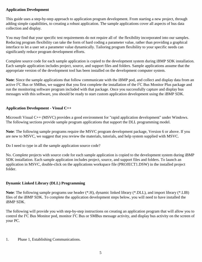
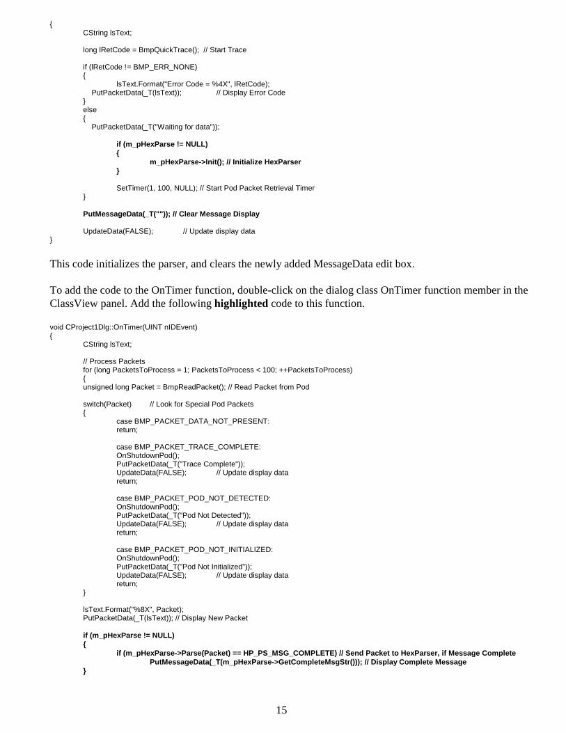
This code initializes the parser, and clears the newly added MessageData edit box.
To add the code to the OnTimer function, double-click on the dialog class OnTimer function member in theClassView panel. Add the following highlighted code to this function.
void CProject1Dlg::OnTimer(UINT nIDEvent) {
CString lsText;
// Process Packetsfor (long PacketsToProcess = 1; PacketsToProcess < 100; ++PacketsToProcess){unsigned long Packet = BmpReadPacket(); // Read Packet from Pod
switch(Packet) // Look for Special Pod Packets{
case BMP_PACKET_DATA_NOT_PRESENT:return;
case BMP_PACKET_TRACE_COMPLETE:OnShutdownPod();PutPacketData(_T("Trace Complete"));UpdateData(FALSE); // Update display datareturn;
case BMP_PACKET_POD_NOT_DETECTED:OnShutdownPod();PutPacketData(_T("Pod Not Detected"));UpdateData(FALSE); // Update display datareturn;
case BMP_PACKET_POD_NOT_INITIALIZED:OnShutdownPod();PutPacketData(_T("Pod Not Initialized"));UpdateData(FALSE); // Update display datareturn;
}
lsText.Format("%8X", Packet);PutPacketData(_T(lsText)); // Display New Packet
if (m_pHexParse != NULL){
if (m_pHexParse->Parse(Packet) == HP_PS_MSG_COMPLETE) // Send Packet to HexParser, if Message CompletePutMessageData(_T(m_pHexParse->GetCompleteMsgStr())); // Display Complete Message
}

16
UpdateData(FALSE); // Update display data
}
CDialog::OnTimer(nIDEvent);}
This new code sends pod packets to HexParse and monitors parser return status. This status providesinformation on the packet parsing operation, and can be used to detect when parser output is available. Themessage text generated by the parser is available from the HexParse GetCompleteMsgStr() function. Here wedisplay parser output of complete bus messages with the MessageData edit box control.
11. Testing default parser output.
You can now build and run the second phase of this sample application. This phase of the application uses theHexParse class to displayed bus messages in a human readable format.
To save your work, click File|Save Workspace on the MSVC menu bar.
To build the program, click Build|Build Project on the menu bar. Correct any errors displayed in the MSVCDebug window.
To run the program, click Build|Execute Project on the menu bar.
At this time your running program should look something like this:
If everything is working correctly, you should see pod packet data being displayed in the PacketData edit boxand bus messages being displayed in the MessageData edit box.
12. Phase 3, Customizing parser output.
Our application currently uses parser default settings to display bus messages. But the HexParse class supportsa number of member functions that can be used to customize parser operation. Our goal in this phase ofprogram development is give the program control of parser output.
We could add individual controls to the form to set or clear parser member functions, but a test system may ormay not need this amount of flexibility. To keep things simple, our application will simply set the HexParsemember functions in the OnQuickTrace function, right after we initialize the parser. To add the code to theOnQuickTrace function, double-click on the QuickTrace button. Add the following highlighted code to thisfunction.

17
void CProject1Dlg::OnQuickTrace() {CString lsText;
long lRetCode = BmpQuickTrace(); // Start Trace
if (lRetCode != BMP_ERR_NONE){lsText.Format("Error Code = %4X", lRetCode);PutPacketData(_T(lsText)); // Display Error Code}
else{PutPacketData(_T("Waiting for data"));
if (m_pHexParse != NULL){m_pHexParse->Init(); // Initialize HexParser
// Set Parser Output Control Variablesm_pHexParse->SetShowStart(TRUE); // Show [Start] or [RptStart]m_pHexParse->SetShowStop(TRUE); // Show [Stop]m_pHexParse->SetShowReadWrite(TRUE); // Show [R] or [W]m_pHexParse->SetShowAck(FALSE); // Show [A]m_pHexParse->SetShowNak(TRUE); // Show [N]m_pHexParse->SetShowBitData(FALSE); // Show Bit Data (0 or 1)m_pHexParse->SetShowByteData(TRUE); // Show Byte Data (00...FF)m_pHexParse->SetShowAbsTime(TRUE); // Show Absolute Timem_pHexParse->SetShowStartTime(TRUE); // Show Start Timem_pHexParse->SetShowBitTime(FALSE); // Show Bit Timem_pHexParse->SetShowByteTime(FALSE); // Show Byte Timem_pHexParse->SetShowBitRate(FALSE); // Show Msg Ave Bit Ratem_pHexParse->SetCompleteOnRepeat(FALSE); // Complete on Repeat
// Slave Address Namingm_pHexParse->SetSlaveAddrName(0x4e, "#PCF8574"); // Slave Address 4E = "#PCF8574"m_pHexParse->SetSlaveNamingEnable(TRUE); // Enable Slave Address Naming
// Slave Address Filtering // Enable Message if:m_pHexParse->SetSlaveAddrEnabled(0x50, FALSE); // Slave Address is NOT 0x50m_pHexParse->SetSlaveAddrFilterEnable(TRUE); // Enable Slave Address Filtering
// Message Data Filtering // Enable Message if:m_pHexParse->SetMsgFilterStr(0,""); // Slave Address is Don't Carem_pHexParse->SetMsgFilterStr(1,"=AK"); // Slave Address is Ackedm_pHexParse->SetMsgFilterStr(2,"=7Fdf"); // 1st Data 0x7F or 0xDFm_pHexParse->SetMsgFilterStr(3,"=AK"); // 1st Data Byte is Ackedm_pHexParse->SetMsgFilterEnable(TRUE); // Enable Msg Filtering}SetTimer(1, 100, NULL); // Start Pod Packet Retrieval Timer
}PutMessageData(_T("")); // Clear Message DisplayUpdateData(FALSE); // Update display data
}
This code sets certain parser properties True or False to control the parser output. During the program testingthat follows, you can experiment by changing these properties and examining the associated changes to theparser output displayed in the MessageData text box.
13. Testing display control options
You can now build and run the third phase of this sample application. This phase of the application uses parserproperties to customize the displayed bus messages.
Save your work, build, and run the program.
At this time your running program should look something like this:

18
If everything is working correctly, you should see pod packet data being displayed in the PacketData edit boxand customizable bus messages being displayed in the MessageData edit box.
14. Phase 4, Expanding control of the iBMP pod.
Up to this point we have been using the iBMP DLL QuickTrace function to initialize the pod and start a trace.QuickTrace works fine, but it forces the application to use a set of default parameters. Now its time to startusing some of the expanded and real-time capabilities of the pod. These capabilities allow the pod to:
1. Synchronize data collection with an external trigger.2. Generate bit timing information.3. Generate a trigger out signal in coordination with a specified bus event.4. Modify its bus voltage logic level.
To add these new capabilities to our application, we will need to call upon a few additional iBMP DLLfunctions. To give a program user control over these new capabilities, we will need to add three (3) newcommand buttons to the form.
When we are done with this phase, our form should look something like this:
Since we will no longer be using the QuickTrace button, we can delete it from the form. Do this by selectingthe button with the mouse, and pressing the delete key on the keyboard. We will continue to use theShutdownPod button as before.

19
To add the three (3) new buttons to your form, resize the form if required, reposition the ShutDown button.Click on the command button control on the MSVC toolbar and draw the buttons on the dialog. Set thecontrol’s caption properties to InitializePod, StartTrace, and StopTrace, and their IDs toIDC_INITIALIZEPOD, IDC_STARTTRACE, and IDC_STOPTRACE.
15. Add code to support the expanded controls.
Now we are ready to add code for the three (3) new buttons we added to the form.
Double-click on the InitializePod button to open the click event function. Add the following highlighted codeto this function.
void CProject1Dlg::OnInitializepod() {
CString lsText;
KillTimer(1); // Stop Pod Packet Retrieval Timer
long lRetCode = BmpInitPod(1); // Connect using IOBoard 1
if (lRetCode != BMP_ERR_NONE){ // iBMP Pod Initialize Failure lsText.Format("Error Code = %4X", lRetCode); PutPacketData(_T(lsText)); // Display Error Code}else{ // iBMP Pod Initialize Success PutPacketData(_T("Pod Initialization Complete")); GetDlgItem(IDC_STARTTRACE)->SetFocus();}
UpdateData(FALSE); // Update display data}
This code calls the iBMP DLL BmpInitPod function to initialize the pod. This function prepares the pod for busmonitoring activities, and accepts a single argument, the number of the interface board connected to the iBMPpod. Board numbers are assigned during board installation. The iBMP SDK supports up to ten (10) interfaceboards in a system. Here we are using board zero (1). The BmpInitPod function performs the pod initializationsequence previously performed as part of the BmpQuickTrace function.
Next we will need to add code to command the pod to start collecting data from the bus. To do this, we will addsome code to the StartTrace command button click event. To enter this code, double-click on the StartTracecommand button, and add the following highlighted code to this function.
void CProject1Dlg::OnStarttrace() {
static BmpTrigOutMem PatternMem; // Trigger Out Bit Pattern Memorystatic BmpTrigOutMem DontCareMem; // Trigger Out Don't Care Memorystatic BmpTrigOutMem TrigPosMem; // Trigger Out Position MemoryCString lsText;
// Initialize pod trigger out arraysfor (int index = BMP_TRIG_OUT_MIN; index <= BMP_TRIG_OUT_MAX; ++index){ PatternMem[index] = 0x00; // Pattern match on 0's DontCareMem[index] = 0xFF; // Don't care about any bits TrigPosMem[index] = 0x00; // Disable all trigger out points}
// Set Pod to Trigger Out if 1st message data byte is Hex 55
// Setup match data, don't care bits, and trigger out pointPatternMem[BMP_TRIG_OUT_MIN+1] = 0x55; // Pattern match on 0x55

20
DontCareMem[BMP_TRIG_OUT_MIN+1] = 0x00; // All bits much matchTrigPosMem[BMP_TRIG_OUT_MIN+1] = 0x01; // Trigger out on 1st data byte
// Command iBMP Pod to start tracelong lRetCode = BmpTraceStart(
FALSE, // EnableBitTiming FALSE, // StartExtTrig BMP_TRIG_OUT_MATCH, // Trigger Out ControlPatternMem, // Bit Pattern MemoryDontCareMem, // Don't Care MemoryTrigPosMem, // Trigger Position Memory250 // Logic Level Threshold);
if (lRetCode != BMP_ERR_NONE){
// iBMP Pod Trace Start Failure
lsText.Format("Error Code = %4X", lRetCode);PutPacketData(_T(lsText)); // Display Error Code
KillTimer(1); // Stop Pod Packet Retrieval TimerGetDlgItem(IDC_INITIALIZEPOD)->SetFocus();
}else{
// iBMP Pod Trace Start Success
PutPacketData(_T("Waiting for data"));
if (m_pHexParse != NULL){
m_pHexParse->Init(); // Initialize HexParser
// Set Parser Output Control Variablesm_pHexParse->SetShowStart(TRUE); // Show [Start] or [RptStart]m_pHexParse->SetShowStop(TRUE); // Show [Stop]m_pHexParse->SetShowReadWrite(TRUE); // Show [R] or [W]m_pHexParse->SetShowAck(FALSE); // Show [A]m_pHexParse->SetShowNak(TRUE); // Show [N]m_pHexParse->SetShowBitData(FALSE); // Show Bit Data (0 or 1)m_pHexParse->SetShowByteData(TRUE); // Show Byte Data (00...FF)m_pHexParse->SetShowAbsTime(TRUE); // Show Absolute Timem_pHexParse->SetShowStartTime(TRUE); // Show Start Timem_pHexParse->SetShowBitTime(FALSE); // Show Bit Timem_pHexParse->SetShowByteTime(FALSE); // Show Byte Timem_pHexParse->SetShowBitRate(FALSE); // Show Msg Ave Bit Ratem_pHexParse->SetCompleteOnRepeat(FALSE); // Complete on Repeat
// Slave Address Namingm_pHexParse->SetSlaveAddrName(0x4e, "#PCF8574"); // Slave Address 4E = "#PCF8574"m_pHexParse->SetSlaveNamingEnable(TRUE); // Enable Slave Address Naming
// Slave Address Filtering // Enable Message if:m_pHexParse->SetSlaveAddrEnabled(0x50, FALSE); // Slave Address is NOT 0x50m_pHexParse->SetSlaveAddrFilterEnable(TRUE); // Enable Slave Address Filtering
// Message Data Filtering // Enable Message if:m_pHexParse->SetMsgFilterStr(0,""); // Slave Address is Don't Carem_pHexParse->SetMsgFilterStr(1,"=AK"); // Slave Address is Ackedm_pHexParse->SetMsgFilterStr(2,"=7Fdf"); // 1st Data 0x7F or 0xDFm_pHexParse->SetMsgFilterStr(3,"=AK"); // 1st Data Byte is Ackedm_pHexParse->SetMsgFilterEnable(TRUE); // Enable Msg Filtering
}SetTimer(1, 100, NULL); / Start Pod Packet Retrieval TimerGetDlgItem(IDC_STOPTRACE)->SetFocus();
}
UpdateData(FALSE); // Update display data}
This code calls the iBMP DLL BmpTraceStart function to tell the pod to start collecting bus data. TheBmpTraceStart function takes seven (7) parameters which are defined in an appendix of this guide. Here we:

21
a. Disable pod bit timing generation.b. Start the trace immediately.c. Generate a trigger out if the first data byte is a 0x55.d. Set the logic level threshold to 2.50 volts.
If the TraceStart function is successful, we initialize the HexParse parser by calling its Init function, and enableOnTimer events just as we did with the QuickTrace button earlier.
Now we will command the pod to stop collecting data from the bus. To do this, we will add some code to theStopTrace button click event. To enter this code, double-click on the StopTrace button, and add the followinghighlighted code to this function.
void CProject1Dlg::OnStoptrace() {
KillTimer(1); // Stop Pod Packet Retrieval TimerBmpTraceStop();PutPacketData(_T("Trace Terminated"));GetDlgItem(IDC_STARTTRACE)->SetFocus();
UpdateData(FALSE); // Update display data}
This code disables OnTimer events, and calls the iBMP DLL BmpTraceStop function to command the pod tostop collecting bus data.
16. Testing parser control options.
You can now build and run the forth phase of this sample application. This phase of the application uses iBMPDLL BmpInitPod, BmpTraceStart, and BmpTraceStop functions to add additional control to our busmonitoring activities.
Save your work, build, and run the program.
At this time your running program should look something like this:
At this point in program development, we have complete control over pod data collection and parserpresentation of bus traffic using hard-coded parameters within the application code.
17. Phase 5, Adding user controls

22
To complete our sample application, we can now add controls to the form that will allow a user to control someor all aspects of pod and parser operation. Since a test program based on the iBMP SDK may not need thislevel of control, we provide source files for Phase 5 only. In operation, Phase 5 of the running program willlook something like this:

23
Appendix A. iBMP DLL Application Interface Descriptions
Visual C++
Dynamic Linked Library (DLL)
BmpDllVer() - Get I2C iBMP DLL Revision
Purpose: This function retrieves iBMP DLL revision information.
Usage: Called by an application to retrieve a iBMP DLL revision information.
Arguments: None
Return: (XX.XX) Major.Minor
Example:
// Add DLL Version to Dialog Title Bar
CString DllVerStr;DllVerStr.Format(_T("MSVC++ iBMP DLL Test - V1.0 using %s V%x.%02x"),
BMPdllname, // iBMP DLL NameBmpDllVer()>>8 , // DLL Major RevisionBmpDllVer()&0xff // DLL Minor Revision
);this->SetWindowText(DllVerStr); // Update Title Bar Caption
BmpQuickTrace() - Quick Trace
Purpose: This function:
1. Finds an external Bus Monitor Plus Pod.2. Initializes the Pod.3. Starts a trace using default parameters (see below).
Usage: The BmpQuickTrace() function is a quick way to start a trace. The function searches the host computerfor an externally attached iBMP pod. Once a Pod is found, it is automatically initialized, and a trace isstarted using the following default parameters:
1. Bit Timing Disabled2. Start Trace Immediate (without External Trigger In)3. No Trigger Out4. 2.5V Logic Level Threshold
See BmpTraceStart() below for default parameter descriptions.
24
The host computer is searched for an externally attached iBMP pod by using interface board numbers established withthe Measurement Computing (previously ComputerBoards) InstaCal board installation and configuration program.InstaCal provides the driver for the iBMP interface board. InstaCal is installed from the Measurement Computing(previously ComputerBoards) InstaCal CD.
Argument: None
Return: BMP_ERR_NONE = No Error DetectedBMP_ERR_PODNOTREADY = Pod Not Ready
Example:
RetCode = BmpQuickTrace; // Start Trace
if (RetCode == BMP_ERR_NONE) // if initialization successful{
// iBMP Pod QuickTrace Success}else{
// iBMP Pod QuickTrace Failure}
BmpCheckBoardNumber() - Check I2C iBMP Interface Board Number
Purpose: This function checks for the presence of a iBMP Interface Board at the specified board number.
Usage: Called by an application to determine if a specific iBMP Interface Board is present in the system.
Arguments: BoardNumber (0...9)
Return: TRUE if board is present.
Example:
// Find Installed iBMP Interface Boards
for (int BoardNum = 0; BoardNum <= 9; ++BoardNum) // for all possible Interface Boards{
if (BmpCheckBoardNumber(9 - BoardNum)) // if Interface Board detected{
pWnd = (CWnd*) GetDlgItem(aiIDC[9 - BoardNum]); // Enable Board ButtonpWnd->EnableWindow(TRUE);
}}
25
BmpInitPod() - Initialize iBMP Pod
Purpose: This function initializes the external Bus Monitor Plus Pod.
Usage: The BmpInitPod() function is called with a single parameter that indicates which interface board ( 0 to 9 ) is connected to the iBMP pod.
The interface board number is established with the Measurement Computing (previously ComputerBoards) InstaCalboard installation and configuration program. InstaCal provides the driver for the iBMP interface board. InstaCal isinstalled from the Measurement Computing (previously ComputerBoards) InstaCal CD.
Argument: BoardNumber (0...9) = iBMP Interface Board Number
Return: BMP_ERR_NONE = No Error DetectedBMP_ERR_BOARDNUMRANGE = Board Number Out-Of-RangeBMP_ERR_BOARDNUMINVALID = Invalid Board NumberBMP_ERR_PODFILENOTFOUND = Pod Config File Not FoundBMP_ERR_PODNOTREADY = Pod Not Ready
Example:
BeginWaitCursor(); // switch to HourGlass cursor
RetCode = BmpInitPod(InterfaceBoardNumber); // Initialize iBMP Pod
EndWaitCursor(); // restore cursor
if (RetCode == BMP_ERR_NONE) // if initialization successful{
// iBMP Pod Initialize Success
}else{
// iBMP Pod Initialize Failure}
BmpTraceStart() - Trace Start
Purpose: This function configures the external Bus Monitor Plus Pod and commands the Pod to start collectingmessage data.
Usage: The BmpTraceStart() function is called by an application to start bus data collection.
Once commanded to start collecting data, Pod data collection begins with either:
a. The next Start condition on the bus, or b. If StartExtTrig is enabled, with the next Start condition following a Pod Trigger In signal.

26
Data collected is held within the external Pod until the BmpReadPacket() function is called by the application to readPod data. For more information see the OnTimer() function in this application.
Arguments: This function is called with the following parameters:
1. EnableBitTiming
This boolean flag enables bit timing data collection.
2. StartExtTrig
This boolean flag enables data collection only after the pod receives an external trigger(high to low) on its Trigger In Port.
3. Trigger Out Control
This BYTE parameter controls the iBMP Trigger Out Port. The Trigger Out Port can generate at signal (high tolow) upon the detection of:
a. Bus Start conditions (BMP_TRIG_OUT_START).b. Bus Stop conditions (BMP_TRIG_OUT_STOP).c. Bus Naks (BMP_TRIG_OUT_NACK).d. Bus Acks (BMP_TRIG_OUT_ACK).e. A Bit Pattern Match on a message slave address or within the first 15 data bytes of a message(BMP_TRIG_OUT_MATCH).
Set Trigger Out Control to BMP_TRIG_OUT_NONE to disable Trigger Out generation.
4. Bit Pattern Memory
An array of 16 bytes used to specify a data bit pattern, where:
0, 1, 2, 3, 4 ...15[A D1 D2 D3 D4 ...D15]| | | | | || | | | | || |_______________________ || ||_______________ |Address R/W Data|------------------| |-------------|[0000000 0] [0000 0000]
a. Array byte [0] is the bit pattern for the message slave address and R/W bit.b. Array bytes [1...15] are the bit patterns for the first 15 data bytes of a message.

27
Each bit of each array byte is matched with each bit of the message slave address or data byte. TheAcknowledge bit following each message byte is skipped. Don't Care bits (see below) are not tested.
5. Don't Care Memory
An array of 16 bytes used to specify Don't Care bits, where:
a. Array byte [0] is the Don't Care bit pattern for the message slave address.b. Array bytes [1...15] are the Don't Care bit patterns for the first 15 data bytes of a message.c. 1 = Don’t Care.
The Most Significant Bit (MSB) of each array byte is matched with the MSB of the message slaveaddress or data byte. The Acknowledge bit following each message byte is skipped.
Don't Care bits (bit value = 1) are not tested. All other message bits, up to the Trigger Position (seebelow), are tested.
6. Trigger Position Memory
An array of 16 bytes used to specify the Trigger Position, where:
a. Array byte [0] is the Trigger Position for the message slave address.b. Array bytes [1...15] are the Trigger Positions for the first 15 data bytes of a message.
Trigger Position only uses the Least Significant Bit (LSB) of each array byte. This LSB marks theposition within a message where the Trigger Out signal is generated if all non-Don't Care message databits up to this point in the message matched the Bit Pattern data. The Acknowledge bit following eachmessage byte is skipped.
7. Logic Level Threshold
This BYTE parameter configures the iBMP Logic Level Threshold. Once configured, bus Clock (SCL)and Data (SDA) signals below the specified voltage are consider to have a zero (0) logic lever.
Set parameter value in the decimal range of 50 to 250 for 0.50 to 2.50 Volts.
If BmpTraceStart() is successful, the Hex Parser is initialized, the User Interface is updated, and the Pod PacketRetrieval Timer is started.
The Pod Packet Retrieval Timer executes its event handler at evenly spaced intervals. This handler retrieves packetsfrom the iBMP Pod, pre-processes the packets, passes the packets to the Hex Parser, and updates the User interface.
The Hex Parser processes a stream of iBMP Pod packets, detects bus events, and generates a stream of text stringssuitable for presentation to the User interface.
Return: BMP_ERR_NONE = No Error DetectedBMP_ERR_BOARDNUMRANGE = Board Number Out-Of-Range

28
BMP_ERR_BOARDNUMINVALID = Invalid Board NumberBMP_ERR_PODFILENOTFOUND = Pod Config File Not FoundBMP_ERR_PODNOTREADY = Pod Not Ready
Example:
// Trigger Out Memory ArraysBmpTrigOutMem PatternMem; BmpTrigOutMem DontCareMem;BmpTrigOutMem TrigPosMem;
// Command iBMP Pod to start trace
RetCode = BmpTraceStart(TRUE, // EnableBitTiming FALSE, // StartExtTrig BMP_TRIG_OUT_NONE, // Trigger Out ControlPatternMem, // Bit Pattern MemoryDontCareMem, // Don't Care MemoryTrigPosMem, // Trigger Position Memory250 // Logic Level Threshold);
if (RetCode == BMP_ERR_NONE){
// iBMP Pod Trace Start Success}else{
// iBMP Pod Trace Start Failure}
BmpReadPacket() - Read iBMP Pod Packet
Purpose: To retrieve a iBMP pod data packet.
Usage: Called by an application to retrieve a iBMP pod data packet following a Start Trace command.
A packet is an unsigned 32-bit number representing iBMP pod status or bus events. There are two types of datapackets, standard packets, and special packets.
Standard Packets
Standard packets represent I2C Bus events. Each standard packet consists of three (3) fields (ID, Time, and Data) withthe following definitions:
Packet ID (0xXX000000)

29
The packet ID field is used to identify the pod events that generated the packet, and bus conditions present atthe time the packet was generated. More than one event can occur in a single packet. Pod events/conditionsinclude:
Events (which caused the packet to be generated)
BMP_INFO_RAP_EVENT Pod Timer Overflow
The iBMP pod includes a 16-bit timer that increments on a 1 microsecondinterval. This event occurs when the timer overflows. Upon overflow, thetimer continues counting from zero.
Unitialized timer counting begins when an Initialize Pod command isissued to the pod. BMP_INFO_RAP_EVENT events are withheld by thepod until the first bus Start condition is detected following a Start Tracecommand.
BMP_INFO_BITTIME_EVENT Bit Detected
If pod bit timing is enabled, this event occurs when the pod detects arising edge on the bus SCL line.
BMP_INFO_START_EVENT Start Detected
Occurs when the pod detects a falling edge on the bus SDA line while theSCL line is high. The first standard packet generated following a StartTrace command will always be a Start event.
BMP_INFO_STOP_EVENT Stop Detected
Occurs when the pod detects a rising edge on the bus SDA line while theSCL line is high.
BMP_INFO_DATA_EVENT Byte Detected
Occurs when the pod detects a rising edge on the bus SCL line during the byteAcknowledge (9th) bit time. This event occurs on all bus byte transfers, includingslave address bytes, extended addressing bytes, and message data bytes.
Conditions (present at the time the packet was generated)
BMP_INFO_SCL_BIT SCL Signal Level
Logical signal level (pod threshold controlled) of the bus Clock (SCL)line.
BMP_INFO_SDA_BIT SDA Signal Level
Logical signal level (pod threshold controlled) of the bus Data (SDA)line. Can be used to determine the logic level of a data bit at a Bit event.

30
BMP_INFO_NAK_BIT Acknowledge Bit Signal Level
Logical signal level (pod threshold controlled) of the bus Data (SDA) lineon Acknowledge (9th) bit SCL rising edge.
Packet Time (0x00XXXX00)
Packet Time is an unsigned 16-bit field that can be used to identify when bus events occur.
The iBMP pod includes a 16-bit timer that increments on a 1 microsecond interval. The timer counting begins when anInitialize Pod command is issued to the pod. The packet Time field identifies the pod timer count when a packet was generated. Upon reaching a timer overflow, the pod generates a BMP_INFO_RAP_EVENT eventand continues counting from zero.
Since pod packets are held within the iBMP pod in internal FIFO memory until read out by the host computer, thepacket Time field represents a real-time recording of bus activity, and provides for non-real-time processing of bus events by the host computer with microsecond accuracy.
Making Time Measurements
If timing is a critical measurement in a bus test procedure, a host computer program controlling the test will need todetermine elapsed time between an initial and final bus event. To make this measurement, the computer program willrecord the packet Time on the initial bus event (Start, Bit, Data, Stop) and will reset a Timer Over Flow count programvariable. The computer program will then count any Timer Overflow events, and record the packet Time for the finalbus event (Start, Bit, Data, Stop).
The elapsed time between the bus events (in microseconds) can then be computed by:
Elapsed Time = (Final Packet Time + (Timer Overflow Count * 0x10000)) - (Initial Packet Time)
For example, if:
a. The initial packet Time is 0xFFFE.b. The pod timer overflows 4 times during the measurement.c. The final packet Time is 0x0002.
then:
Elapsed Time = (2 + (4 * 0x10000)) - (0xFFFE) = 0x3004 = 196,612 uSec
Packet Data (0x000000XX)
Packet Data is an unsigned 8-bit field that can be used to identify the value of a message byte. The first (and second for10-bit addressing) byte following a bus Start event is the message slave address, and subsequent bytes are messagedata.
Special Packets
Special packets are used to insert iBMP pod status into the packet stream. Each special packet is identified by itsspecific value. These packets include:

31
BMP_PACKET_DATA_NOT_PRESENT Data Not Present
iBMP pod FIFO is empty. No dataavailable.
BMP_PACKET_TRACE_COMPLETE Trace Complete
Trace terminated on FIFO overflow. All pod data collectedup to the point of FIFO overflow has been read.
BMP_PACKET_POD_NOT_DETECTED Pod Not Detected
The iBMP pod or interface board not detected.
BMP_PACKET_POD_NOT_INITIALIZED Pod Uninitialized
Attempt to read data from an uninitialized pod.
Example:
void CMSVCBMPlusDLLTestDlg::OnTimer(UINT nIDEvent) {
unsigned long PodPacket;long PacketsToProcess;
for (PacketsToProcess = 1; PacketsToProcess < 100; ++PacketsToProcess) // Process Packets{
PodPacket = BmpReadPacket(); // Read Packet from iBMP Pod
if (PodPacket == BMP_PACKET_DATA_NOT_PRESENT) // if no Packets available return;
ProcessPacket(PodPacket); // Process Packet
}
CDialog::OnTimer(nIDEvent);}
BmpTraceStop() - Trace Stop
Purpose: This function stops message data collection.
Usage: The BmpTraceStop() function is called by an application to stop bus data collection. Once stopped, datacollection can be restarted with the BmpTraceStart() or BmpQuickTrace functions.
Arguments: None
Return: BMP_ERR_NONE = No Error Detected

32
Example:
BmpTraceStop(); // Command iBMP pod to stop trace
BmpShutdown() - iBMP Pod Shutdown
Purpose: This function terminates iBMP Pod activity.
Usage: The BmpShutdown() function is called by an application to terminate iBMP Pod activity. Onceshutdown, the pod can be restarted with the BmpInitPod() or BmpQuickTrace functions.
Arguments: None
Return: BMP_ERR_NONE = No Error Detected
Example:
BmpShutdown(); // Terminate iBMP pod activity