i applications of aerospace technology in industry - … · applications of aerospace technology in...
TRANSCRIPT

Applications ofAerospace Technology
in Industry
A TECHNOLOGY TRANSFER PROFILE
NONDESTRUCTIVE TESTING
(NASA-CR - 126 574 ) APPLICATIONS OF AERS~AC N72- 24TEC.HNOLOGY IN INDUSTRY: .A TECHN2OLOGYTRANSFER PROFILE, NONDESTRUCTIVE: TESTING(Denver Research Inst.) Apr. 1972 109 p Unclas
| _ bCSCL 14D G3/15 31341
Reproduced by
NATIONAL TECHNICALINFORMATION SERVICE
U S Department of CoriimerceSpringfield VA 22151
I
https://ntrs.nasa.gov/search.jsp?R=19720017832 2018-08-31T18:30:43+00:00Z

ACKNOWLEDGEMENTS
This technology transfer profile was prepared for the TechnologyUtilization Office, National Aeronautics and Space Administration, as partof the Project for the Analysis of Technology Transfer (PATT) at theDenver Research Institute, Denver, Colorado. This project is directed byJames P. Kottenstette of the Denver Research Institute, with assistancefrom James E. Freeman, William M. Hildred, Linda Jensen, F. DouglasJohnson, Jerome J. Rusnak and Eileen R. Staskin.
Much of the information was gathered with the assistance of NASAin-house and contractor personnel who participated in the developmentand application of the technology discussed.
The technology reviewed in this presentation and the applications notedrepresent the best knowledge available at the time of preparation. Neitherthe United States Government nor any person acting on behalf of theUnited States Government assumes any liability resulting from use of theinformation contained in this document, or warrants that such use will befree from privately owned rights.

APPLICATIONS OF AEROSPACE TECHNOLOGY
IN INDUSTRY
A TECHNOLOGY TRANSFER PROFILE
NONDESTRUCTIVE TESTING
- Prepared for -
The Technology Utilization Office
(Code KT)
National Aeronautics and Space Administration
Contract NSR-06-004-063
- Prepared by -
Industrial Economics Division
Denver Research Institute
University of Denver
April 1972
//

TABLE OF CONTENTS
Section
PROFILE HIGHLIGHTS .
INTRODUCTION
I. AN OVERVIEW OF THE NONDESTRUCTIVETESTING FIELD
II. NASA CONTRIBUTIONS TO THE FIELD OF
NONDESTRUCTIVE TESTING
III. DISSEMINATION OF NASA CONTRIBUTIONS.
IV. A TRANSFER PROFILE .
V. A FOCUS ON ISSUES .
ATTACHMENT I.
11
* 21
27
33
A Brief Description of Common
Nondestructive Testing Methods 35
ATTACHMENT II.
ATTACHMENT III.
AT TACHMENT IV.
Selected NDT Developments
That Have Resulted From
NASA-Sponsored Research .
Tech Brief Exhibit
Summaries of Technology
Transfer Reports Involving
NASA-Generated Nondestructive
Testing Technology .
REFERENCES.
v
1
3
43
59
69
109
P/·V

PROFILE HIGHLIGHTS
Today's manufacturers are continually confronted by demands
for increasingly complex products, systems, and materials that, atthe same time, must be safer and more reliable. As a result, non-destructive testing is being used more and more to assure the integrityof manufactured products, to control production processes, to betterunderstand raw materials, and to predict failure of major structuresafter they are in service.
In many of NASA's programs, where failure often meansdisaster, extremely high quality and reliability are fundamental con-siderations. In the course of meeting such requirements, NASA hasaffected virtually every dimension of the nondestructive testing field,from the design and application of test equipment to the training ofNDT specialists. To enhance the transfer of such new NDT technologyto nonaerospace users, the Space Agency has actively promoted, itsdissemination through publications, special conferences and technicalsocieties. As a result, innovations which have their roots in the spaceprogram are helping to make safer and more reliable earthbound
products.

'4
INTRODUCTION
Nondestructive testing (NDT) is, by definition, the evaluation ofa part or system without impairing its usefulness. While certaintechniques for nondestructive testing existed prior to 1920, the installa-tion of the first radiographic laboratory at the Watertown Arsenal iscommonly recognized as the birth of the NDT field. At Watertown,X-rays and photographic film provided man's first glimpse at theworld within a solid material.
Today almost all known forms of energy and energy-detectingdevices serve to probe engineering materials nondestructively. Itemsare observed, smelled, felt, measured, X-rayed, magnetized, vibrated,acoustically excited, and heated all in the name of NDT. No one form ofenergy nor any one NDT method is the answer to all or even a largeportion of the nondestructive testing needs. Each technique has itslimitations and the methods usually compliment rather than competewith one another. In some cases it is even necessary to developspecial NDT methods along with the products to which they will beapplied.
Underpinning the rapid growth of the NDT field is the ever-present demand for improved quality in the products purchased bygovernment, industry and consumers. When finished hardware becomesso expensive that not even a single component can be routinely sacrificedto estimate quality and reliability, or so critical that each must bethoroughly inspected prior to and during use, nondestructive evaluationbecomes technically necessary and economically wise.
With these constraints as a backdrop, it is no surprise that thespace program has played a major role in the recent growth of NDT.In this profile NASA's contributions to the major growth trends in thefield are studied in Section II. To set the stage for this study, Section Iprovides a brief overview of the NDT field. Sections III and IV focuson the ways in which people outside the space program acquire and useNASA-generated NDT technology.

SECTION I. AN OVERVIEW OF THE NONDESTRUCTIVETESTING FIELD
For several years prior to World War II, nondestructive test-
ing (NDT) techniques and equipment skirted the edge of industry.
Industrial management of the 1920's and 30's viewed the concepts and
systems of NDT as costly curiosities not yet adaptable to large-scale,
automated manufacture. It was felt that the systematic testing of mate-
rials, components, and products without impairing their usefulness was
somewhat of a luxury and that periodic destructive tests were ample.
As a result, the science of NDT lingered in the laboratories until the
early 1940's.
Like so many other technologies, NDT received a great
impetus from World War II, and during those years it was actually
formalized into a science with the establishment of the American
Industrial Radium and X-Ray Society. This organization later evolved
into the American Society for Nondestructive Testing (ASNT). The
Society now consists of more than 5, 000 members, as well as 75 cor-
porate members, and publishes several books and a monthly journal,
Materials Evaluation.
With the added impetus of continued military developmen't--the
Korean conflict, the Vietnam War--and a large-scale U.S. space effort,
NDT has undergone considerable expansion since the 1940's. Within
the past decade, for example, rapid advances in materials technology
and increasingly stringent aerospace and commercial specifications
have moved NDT out of its singular role of quality control, into a newand still expanding role as a diagnostic and predictive tool to be used in
all phases of design, development, test and field evaluation.
What techniques and systems now comprise NDT? How much of
a transition has been made from laboratory to manufacturing plant?
What industries and applications offer the greatest potential for NDT
use? How large is the market for NDT equipment, and at what rate is
it growing? What does the future hold for NDT?
NDT Techniques
True to its definition as a science which probes materials or
objects in a manner that will not impair their future usefulness, NDT
most commonly includes radiography, ultrasonics, eddy current,

4
magnetic particles and dye penetrants (see Attachment I). Recent
advances in the discipline include infrared, microwave, acoustic
emission, real-time X-ray and neutron imaging, acoustic and laser
holography, and liquid crystals. Ultrasonic and radiographic methods
are typically used for in-depth analysis; while holography, eddy current,
magnetic particles, and thermal methods are used for the detection and
identification of near surface anomalies.
Applications of NDT
Although some of the newer NDT concepts are presently beyond
the workaday use of manufacturers, nonetheless, NDT has made
significant inroads into inspection of products after use as well as into
automated, mass manufacture. Table 1-1 summarizes the application
areas, along with functions and examples of NDT.
TABLE 1-1. APPLICATIONS, FUNCTIONS, AND EXAMPLES OF NDT*
AREAS OF FUNCTION EXAMPLES
APPLICATION PERFORMED
Research & Evaluating materials, components Measuring fatigue in metals,
Development and parts; comparing and evaluating detecting cracks in welds,
fabrication and assembly techniques; and non-bonds in bondeddata acquisition. materials.
Process Measuring process variables and Radioisotope thickness
Control providing control information. gauging.
Quality Detecting and locating anomalies Poor adhesive bonding,
Control in materials, defective parts, etc; cracks in welds, contaminated
detecting and locating fabrication transistors, non-uniform
and assembly defects; evaluating porosity in metals.
the production process.
In-Service Detecting flaws, defects, wear Locating corrosion inside gasEvaluation and deterioration of items in field tanks, detecting moisture in
use without major disassembly. bonded wing structures onaircraft, etc.
* Source: Research Triangle Institute, 1968.
Quality control applications are by far the dominant factor. In
the steel industry, for example, there is a heavy concentration of

5
production-line NDT systems. This is not surprising in view of thefact that considerable NDT research has been done in metals and that
the amount of available data on metals properties and behavior isextensive.
Typical of NDT uses in manufacture is an installation at Armco
Steel Company in Middletown, Ohio, producer of steel pipe. Here, afluoroscopic system provides 100 percent inspection of spiral-welded
pipe at the rate of 20 to 40 feet per minute. The plant has operatedthis system 24 hours per day, 7 days per week, beginning early in
1971. Other users of similar systems include American Bridge
Company in Orange, Texas, which operates four NDT units .on aproduction-line basis; A. O. Smith, Houston, Texas, makes use'of fivesuch systems; Bethlehem Steel in Steeltown, Pennsylvania uses three
systems (Johnson, 1971).
While the plastics industry has not yet made broad use of NDTmethods in process control, a San Diego firm, Tetrahedron Associates,
Incorporated, has developed a dielectrometer that measures molecular
weight changes in thermosetting resins during cure. As the resin isheated and reaches its gel point and final cure, these changes -are
tracked dielectrically to within one or two seconds. A press operator.can then determine the optimum point at which to close the press byreading the condition of the resin. In later development, Tetrahedron
joined forces with Pasadena Hydraulics, Incorporated, Pasadena,California, one of the largest producers of laminating presses& in'the
United States. By using its dielectrometer to control a laminatingpress, Tetrahedron provided laminators-with a press that cycled accord-
ing to the condition of the material rather than any prearranged process-ing schedule. The result is relatively void-free laminates and more
efficient use of resin. Raytheon Company reported a 25 percent
reduction in scrap using the dielectrometer in circuit-board production.
Other examples, taken from the files of ASNT, illustrate the
benefits that have been gained by users of NDT (Johnson, 1971):
* Bridge engineers have found that by using the new, exotic, high-strength steels and welding the'members together instead of
using rivets, they can save 20 percent in the amount of steel
used. But these new steels are nondestructively tested-when'!
they are made, and the welds are radiographed on the j-ob.
Arthur L. Elliott, chief bridge planning engineer for the

6
California Division of Highways, reported savings of five million
pounds of steel in a bridge where 27 million pounds of the metal
was used. And it is a better bridge because the welded steel is
working almost up to its capacity, thanks to NDT.
* An airline saved $1, 500 per jet aircraft by using X-rays to test
the honeycomb structure inside the wings, according to
Captain Paul J. Slayden, Eastern Airlines' director of quality
control.
* Destructive test specimen costs amounting to $180, 000 a year
have been saved by Northrop Norair, according to E. C. Bennett,
chief of Norair's Quality Division.
* National Airlines saved some $210, 000 in 1968 by the increased
application of nondestructive testing techniques to the maintenance
of its aircraft fleet.
The Market for NDT
The net result of NDT's partial transition from the laboratory
to the manufacturing plant is a burgeoning business, estimated in 1967
at $6 billion yearly in terms of wages, equipment, and maintenance by
John A. Reynolds, vice president and technical director of Picker
Corporation, a leading producer of NDT equipment (Johnson, 1971).
When asked to describe the current size of the U. S. market for NDT
equipment, Ralph E. Turner, director of Industrial Trade Relations,
Radiography Markets Division, Eastman Kodak Company, and president
of ASNT, provided the market analysis illustrated in Table 1-2.
TABLE 1-2. PROJECTED MARKET GROWTH FOR NDT EQUIPMENT*
1968 1973 Average Growth
Radiography $38,000,000 $ 65,000,000 17%Ultrasonics 25,000,000 65,000,000 21All Other Methods 20, 000, 000 50, 000, 000 20
TOTALS $83, 000, 000 $180, 000, 000 20%
* Source: Turner, 1971.

7
The growth rate, of course, is dependent upon many factors.Among the most important are:
* The appearance and acceptance of any new and improvedproducts.
* The acceptance of NDT in many applications is dependent oncodes and specifications (bridges, pipelines, automobiles, etc.),
legal aspects (such as the manufacturer's responsibility for hisproducts), the military situation, and the state of the economy.
* The acceptance of NDT as a quality control tool, which implies
that a strong educational effort is a requirement.
Assuming favorable market conditions continue, to what newindustries will NDT equipment and supplies be sold and why? Andwhat deterrents are there likely to be to future growth even undersatisfactory market conditions?
Dr. Robert C. McMaster, professor of welding engineering at
Ohio State University, author of a nondestructive testing handbook,and a well-known authority on NDT, believes that the consumer productsindustries eventually will find the greatest need for such equipment.
"With new government regulations and consumer pressures forimproved product performance and safety coming on the scene," explains
McMaster, "manufacturers of aircraft, automobiles, railroad equip-ment, and chemicals will have to install such devices to protect theconsumer and themselves. There has been great interest expressedby insurance companies in NDT systems particularly as claims and thecost of product replacement rises sharply" (McMaster, 1971).
Protecting the lives of personnel using hazardous products is a
key reason for increased use of NDT, according to Carlton H. Hastings,
Space Systems Division, Avco Corporation, Lowell, Massachusetts.
"The emergence of hazardous products, such as the supersonic trans-
ports, nuclear power plants, and high-speed trains point to the need
for NDT to protect the public at large. Factors that will deter the
growth of NDT in certain areas are the lack of knowledge about certain
techniques--such as ultrasonics--and the high cost of NDT"(Hastings, 1971).

8
Turner sees specific limitations in certain methods as obstaclesto progress. "One deterrent to progress in the use of ultrasonics, forexample," says Turner, "is the fact there is only a crude image systemas opposed to the sophisticated imagery of X-ray. On the other hand,X-ray suffers from lengthy time necessary for access to data (from10 to 15 minutes). "
McMaster, Hastings, and Turner, three of the top authoritiesin NDT today, agree that ultrasonics holds the greatest potential forgrowth. Portability, lack of danger from radiation, and capability forgreat depth of penetration are some of the reasons cited for ultrasonics'healthy outlook. Ultrasonics experts feel that closed-loop productionmachines using ultrasonic monitors may eventually make it possible toproduce potentially hazardous products safely and with great reliability.
Although most of the newer, more sophisticated NDT methods--such as holography, acoustic emission, and neutron radiography--arethought of as too costly or unwieldy, the intense need for qualitycontrol devices in industry is producing some noteworthy exploration.In the tire industry, for example, stiffening federal regulations andstandards have caused producers to seek out NDT as a means ofexerting tighter control over production procedures (Business Week,1971).
Trends and Projections
Against this backdrop of increasing equipment sales andincreasing awareness of the need for NDT equipment by industry, newand significant trends are emerging. One of the most important is theability inherent in acoustic emission techniques for predicting failureof systems. Machine Design magazine, in a comprehensive article onNDT, explained this trend: "It has been known for years that deformingmaterials make noise because of the generation of stress waves. Butit is only recently that this sound could be used to detect flaws. Theflaws (in welding) can be detected about 20 to 45 seconds after the weldis made and produce identifiable emissions for about 20 minutes after-ward. The technique has been applied successfully to resistance, gas-tungsten arc, and submerged arc welding" (Lavoie, 1969). Thisdevelopment has implications across the entire spectrum of industries,especially those where equipment or structural failures producecatastrophic consequences.

9
Another trend that offers the promise of continued growth forNDT comes in the form of a stern challenge. George Martin, programmanager for materials and producibility, North American RockwellCorporation, told a 1969 Air Force conference on NDT of plastic/composite structures, "We see NDT results, but we don't know whatthey mean in terms of properties. Good NDT is determining properties,not defects. In metals, we have tremendous empirical knowledge fromthe hounding of holes--finding cracks and determining their effect. Weneed a shortcut for composites." Other comments coming from thisconference indicate that NDT must be coupled to design--shouldinfluence it, not compromise it (Wessling, 1969).
Just as the steel industry now makes use of eddy current
methods and fluoroscopic techniques in on-line mass production tech-
niques, so will the composites field depend upon other emerging typesof NDT for its eventual mass manufacture evolution. First, as withmetals, design parameters must be established through NDT, and thenthe equipment can be changed to monitor and control manufacturingprocesses.
Conclusion
Three factors point the way to healthy NDT growth. First, thepromise already demonstrated by NDT methods as on-line quality controldevices suggests that these systems will continue to evolve into themanufacturing world. Second, industry is further heartened by theemergence of equipment to develop a better understanding of rawmaterials and their influence on the production process. Third, theability to recognize incipient failure in structures is a powerful toolthat will find new application in areas where failure has serious economicor human costs. With these three key factors in operation, it is apparentwhy vigorous growth is forecast for the NDT field. Basic to it all,however, is a general acceptance of the need for greater productquality and safety, particularly as systems and materials grow morecomplex, expensive and hazardous.
Section II examines the ways in which the U.S. space programis contributing to these important societal needs.

-5

SECTION II. NASA CONTRIBUTIONS TO THE FIELD OFNONDESTRUCTIVE TESTING
NASA has maintained a crucial interest in the techniques and
equipment for nondestructive testing, and with good reason--without
NDT, the total space effort could not have enjoyed such a high degree
of achievement. As a result, nondestructive testing is one of the most
important technologies to experience significant growth through the
space program.
While NASA and its contractors frequently used commerciallyavailable, off-the-shelf NDT equipment, many new techniques had to
be developed to solve the unique problems confronting aerospace
engineers. The range of technical contributions by NASA is found to
cut across the entire spectrum of activity in the field of nondestructive
testing; NASA personnel and contractors have produced innovations
ranging from improvements to traditional techniques, such as radio-
graphy and ultrasonics, to the implementation of advanced new tech-
niques such as neutron radiography, acoustic emission and holography.
Space Program Applications of NDT
Engineers are continually challenged by the conflicting demands
associated with aerospace applications. Designs featuring minimum
safety factors must be balanced by the quality and reliability require-
ments for man-rated systems of amazing complexity and sophistication.
The conflicts arising from this "have your cake and eat it too" situation
were addressed by anAgency-wide, quality assurance policy established
in October 1961. In implementing this policy, nondestructive testing
techniques were heavily relied upon for assessing the integrity of basic
materials and for the in-process discovery of material and fabrication
deficiencies. In most cases, destructive or proof-testing methods were
found to be inappropriate for technical and economic reasons
(Weiss, 1971). The following discussion provides a perspective on the
broad use of NDT in the space program.
Materials evaluation. New materials and new concepts for
materials considered for use in the space effort were required to be
compatible with the hostile environments associated with space flight--
for example, temperature extremes ranged from the fiery heat of
propellant combustion and capsule reentry into the earth's atmosphere,
Preceding page blank

12
to the numbing cold of cryogenic propellant storage and transfer. Todetermine material properties and discover defects in these materials,nondestructive testing was used throughout their development.
Materials joining. The problems of joining materials foraerospace use is a story in itself. The first stage of the Saturn Vbooster (S-IC) requires more than 5, 000 feet of welds, all of which are100 percent radiographically inspected in at least two views.Approximately 20, 000 feet (almost 4 miles) of 70 mm radiographicfilm are used during the inspection of each booster. Since conventionalradiographic techniques were found to be expensive, slow, and hazardousto personnel, NASA, in cooperation with the Boeing Company, developeda semi-automatic radiographic system to inspect the Saturn weldsrapidly and safely. Total man-hours required for exposing, processing,and reviewing film were reduced by 50 percent. In addition, this newequipment reduced the radiation hazard to the point where techniciansmay work within 10 feet of an X-ray unit instead of the previous50 feet, thereby reducing the total time the work area must be cleared(Neuschaefer, 1969). The fact that not a single flight or ground testfailure has been caused by a defective weld is evidence of the importanceof such NDT techniques.
Another perspective on NASA's interest in NDT is expressed bythe immense effort associated with nondestructive testing on theSaturn V vehicle. Table 2-1 illustrates the major NDT activities.
TABLE 2-1. SATURN V NONDESTRUCTIVE TESTING*
APPROXIMATENDT REQUIREMENTS MAGNITUDE
X-Ray of Fusion Welds 1.5 MilesX-Ray of Castings and Forgings 100X-Ray of Transistor and Diodes 5, 000Ultrasonic Inspection of Welds 0.4 MilesUltrasonic Inspection of Adhesive Bonds 1,350 Ft. 2Ultrasonic Inspection of Tubing 5 MilesEddy Current Inspection of Tubing 6 MilesDye Penetrant Inspection of Welds 2. 5 MilesSonic Inspection of Adhesive Bonds 5, 776 Ft. 2
* Source: Zoller, 1966.

13
These statistics apply only to the vehicle itself and do notinclude the tremendous number of NDT tests required for support
equipment (Musser, 1969).
Safety factor. Weight is one of the fundamental considerations
in spacecraft and launch vehicles design; it presently costs about$1, 000 to place a single pound of payload into earth orbit (Normyle,
1970). As a result, engineers are continually confronted with thetradeoffs of a safe design at a minimum weight. The design safety
factor, to a large degree, represents the uncertainty associated with
material quality, strength properties, and tolerance to inherent defects.
By providing useful information about properties and flaws, nondestruc-tive testing has played a vital role in the reduction of Apollo/Saturndesign safety factors and, thereby, increased the scientific and
exploratory capability that would be built into the vehicle.
Quality assurance. Probably the greatest role for NDT in thespace program has been to assure the reliability and quality of hardware
that simply must not fail. A single crack in a metal, a flaw in an
electronic component, a defective seal, or a warp in a structural
member could produce catastrophic consequences. At stake are human
lives, millions of dollars and national prestige. Furthermore, the
parts, components, and systems that must function properly for a suc-
cessful mission number in the hundreds of thousands. Nondestructive
testing has been instrumental in the attainment of preestablished quality
and reliability levels upon which designs have been based. This is one
of the basic consequences of the NASA quality assurance policy.
NASA Contributions to NDT
NASA's pervasive utilization of nondestructive testing has
produced numerous technological and economic contributions to the
field. As illustrated in Attachment IV, NASA has been deeply involved
in the preparation of training manuals, miniaturization of equipment,
improving resolution and sensitivity of test instrumentation, and many
other aspects of NDT. The remainder of this section will be devoted
to selected NASA contributions to two new technologies emerging in
the NDT field: predicting service life and automated systems.
Attachment II, by contrast, focuses on singular NASA innovations
acknowledged because of their individual technological and economic
significance.

14
Predicting service life. Nondestructive testing is evolving
beyond the simple identification of flaws and becoming an integral partof the overall evaluation of materials. Even the name has been changedto the more encompassing concept of nondestructive evaluation (NDE).
This new identity is best illustrated by considering its role in predictingincipient failure and eventually useful service life.
Interest in predicting service life for electronic components has
intensified as electronic systems have become more complex and per-
vasive. The overall reliability of these systems is dependent upon thesingular reliability of individual components. Thus, the need for safe
and reliable performance of aircraft, power distribution systems, and
spacecraft, as well as many consumer products, demands guaranteedreliability of individual components. Routine functional tests offer
little possibility of predicting service life; destructive tests on a sampling
basis only add a probabilistic dimension to the evaluation. As a result,
interest has turned to nondestructive testing techniques.
In 1964 the Boeing Company, a NASA contractor, procured anautomated infrared test station for checking electronic components andassemblies. Initial use of the system was to establish a "normal"infrared pattern along with allowable deviations from that pattern forselected electronic assemblies. Because of variable surface emissivi-ties, the Lesting effectiveness was limited, and Martin Marietta
Corporation was given a NASA contract to develop a constant emissivitycoating for electronic components and printed circuit boards. Workingwith manufacturers as well as in house, Martin found a dozen suitablecoatings. Infrared testing of electronic components, assemblies,and microcircuits has gained wide application as a direct result. Notonly is component quality assured, but the technique has successfullydetected misapplied semiconductors, located problems in module designand pinpointed heat pockets.
Accurate prediction of service life for aerospace structures isfar more difficult. In fact, one trend that is emerging emphasizescontinuous monitoring of structures rather than predictive testing. Anotable exception to this trend, however, is evident in the proof-testingof pressure vessels. At one time a practice of questionable value, theproof pressure test is becoming one of the most reliable nondestructivetechniques for assuring safe operating life. NASA experiences duringrecent years have shown that the use of NDT and pressure testingguided by fracture mechanics principles can insure that there are no

15
flaws of sufficient size to cause failure during the service life of a pres-
sure vessel (Tiffany, 1970). The implication for traditional NDT
inspection is that accept/reject criteria are now more rationally based
on critical flaw sizes, not on the assumed capability of inspection
equipment (Weiss, 1971). The significance of this development is that
such structures no longer need be scrapped because of the presence of
harmless flaws, and undetected flaws need not be an operational concern.
Many costly and tragic structural failures could be avoided if
systems were available for continuously monitoring structures for
incipient failure. Although this statement is fundamental and obvious,
it nonetheless describes a very elusive objective which has been sought
for years (Dau, 1971). Consider the following experiences of a major
oil company during a recent six-month period:
* A large carbon steel pressure vessel developed 139 cracks
after only a few weeks of operation.
* A stainless steel weld overlay inside a 265-ton reactor
cracked during hydrostatic testing.
* Several Hastalloy-lined pressure vessels were lost through
corrosion failure.
Yet all of these pressure vessels were designed, fabricated, and
inspected in accordance with requirements of the ASME Boiler and
Pressure Vessel Code (Ebert, 1970).
Failures of major structures such as bridges, aircraft, and
ships, although infrequent, are catastrophic events. Because of their
critical nature, such structures receive periodic inspection and
maintenance aimed at assuring safe operation, yet failures occur. The
need for continuous monitoring of critical structures is now present; it
can be expected to endure and eventually result in the widespread
application of systems which predict remaining service life.
Of the several techniques appropriate to assessing structural
integrity, acoustic emission holds the greatest promise for broadening
this needed capability. The technique has been used to detect flaws in
welds, stress-corrosion cracking, hydrogen embrittlement, and

16
failure in bonded materials. In a review article for Materials
Research and Standards it was concluded that:
The utilization of acoustic emission in assessment of
structural integrity is also in its infancy. Greatprogress has been made in the study of pressure ves-sels, primarily in initial evaluation before they are putinto service. Proof testing and continuous monitoringof a wide variety of structures can be visualized:structures such as pressure vessels, pipelines, air-planes, buildings and bridges could be amenable toacoustic emission techniques. In-process monitoring
of welding, rolling, solidification of casting, and otherfabrication techniques is also conceivable. This list ofpossible future applications could be greatly extended,
but it should be apparent now that the application ofacoustic emission to problems of practical importancehas only begun and that this technique has great potential(Liptai and Harris, 1971).
Some of the earliest development work with acoustic emission
was undertaken by NASA. Lacking suitable NDT equipment for deter-mination of adhesive bond strength in honeycomb structures, NASAinitiated a program aimed at developing such equipment in 1964. Anultrasonic emission detector and methods of equating signal level tomechanically imposed stresses in bonded structures were developed.As a result of this work, the bond strength of adhesively joined struc-tural members can now be qualitatively assessed (Beal, 1967).
Although it will continue to be used for fault finding, the mostpromising and most difficult application for acoustic emission is
predicting failure. When a solid material undergoes plastic deforma-
tion, energy is released. Part of the energy is converted to elastic
waves which can be detected at the material surface using conventional,high-sensitivity ultrasonic sensors, thereby recording an acoustic
signature of the event. Several features of acoustic emission make it
ideal for monitoring structures for incipient failure. First, plastic
deformation is detected immediately after it occurs, thus facilitating
rapid analysis of the event. Second, the system can be conveniently
monitored remotely, with only the sensors required to be near the
emission source. Third, the source of the signal can be accuratelypinpointed and then related to its stress environment.

17
One of the major technical problems limiting the application ofacoustic emission to prediction of incipient failure is that of energysignature identification. In the case of aircraft and nuclear reactors,for example, a myriad of acoustic energy sources are operatingcontinually. Pumps, valves, and flow turbulences all act to provide anoise environment from which the desired signal must be discriminated.A solution to this problem may be found in the pioneering work that theJet Propulsion Laboratory has done in signal and image enhancement.
The problems of correcting various photometric, geometric,and frequency response distortions from spacecraft television camerasare akin to the problems of identifying and classifying acoustic emissionsfrom a part under stress within an otherwise "noisy" environment. Inthe early days of the Ranger's TV transmissions from the moon, JPLengineers and scientists received data that contained more noise thandesired signal. In dealing with the problem, computer techniqueswere successfully developed to retrieve the desired signals from thebackground noise.
Automated systems. The driving force behind the growth ofautomated NDT is the market demands for higher quality and betterperforming products at lower cost. Translated to the manufacturer,these demands mean production processes must be faster, have bettercontrol over end-product characteristics, and minimize the humanlabor element. The rapidly growing interest in automated processesis representative of thinking which emphasizes prevention rather thandetection and cure. The ultimate goal is optimum process control thatassures complete product quality and thereby redefines the need toperform inspection.
Automatic control systems are conveniently classified as eitherclosed-loop or open-loop systems. The most desired principle ofoperation is the closed-loop system, because the true state of theprocess output is continually monitored and adjusted when deviationsfrom programmed performance occur. The key to closed-loop controlis a "feedback" signal for comparison with a command signal. Open-loop systems are then characterized by the absence of a feedback signal.It is in the output measurement and feedback that NDT principles willplay a vital role in the achievement of optimum process control.
The pursuit of optimum manufacturing control is an evolutionaryprocess, which requires several incremental advances to the state-of-the-art. The first stage beyond straight manual inputs is semi-automated

18
systems incorporating both manual and machine inputs. This stageis typically followed by fully automated production processes that,because of inherent weaknesses, continue to require limited inspection.An outgrowth of this progression is automation of inspection techniques.The final stage combines the technologies of automatedproduction alongwith automated inspection to provide optimum system control. Severalindustries have been successful in automating production, but only afew firms have successfully automated the inspection function.
Attempts to automate the inspection function have seen datastorage techniques become widespread. Typically, these types ofsystems perform a nondestructive inspection and record the resultsfor subsequent interpretation by highly skilled technicians or engineers.This type of open-loop system has been employed extensively by NASA.The semi-automatic system for radiographic inspection of Saturn welds,described earlier, is an example of such a system.
A second NASA contribution to testing technology was the out-growth of a problem posed by an unusual hardware configuration. Amechanized ultrasonic scanning system for evaluating welds wasdeveloped after commercially available radiographic equipment wasdeemed unsatisfactory. Manual ultrasonic testing was painfully slow,and the size of the tanks precluded the use of immersion test methods.At the heart of this NASA-developed system is an ultrasonic watercolumn probe, which contains an ultrasonic transducer enclosed within awater-filled cylinder. The benefits of automated inspection are dramati-cally illustrated by this system. Scanning speeds have been increasedfrom 12 feet per hour to 300 feet per hour, and a higher degree ofreliability has been achieved.
A third NASA development is particularly interesting becauseof its contributions to both trends--automated systems and predictingservice life. An ultrasonic system has been developed to automaticallydetect and record the propagation of a fatigue crack. Fatigue refers tothe failure of materials under the action of repeated stresses. Bymonitoring the growth of fatigue cracks and knowing the stress environ-ment of a part, it is possible to predict accurately remaining servicelife for a part.
The NASA-developed system employs an ultrasonic reflectiontechnique to monitor the leading edge of a propagating fatigue crack.

19'
A piezoelectric transducer, which is water-coupled to a test specimen,generates an ultrasonic beam that is partially reflected from the cracktip and partially reflected from a reference reflector plate. The trans-ducer's position is automatically adjusted until the amplitudes of thetwo reflected signals are equal. Growth of the crack causes animbalance in the amplitude of these reflected signals and produces anerror voltage. This error signal activates a servo-motor, whichmoves the transducer until the signals are balanced again. This dis-placement of the transducer is then used to measure the advance of thecrack.
The most difficult problem in achieving fully automated, closed-loop control is the generation of a useful signal to feedback to a con-troller. Even with today's sophisticated equipment, highly trainedtechnicians are often required to interpret test results. Furthermore,this interpretation tends to be more qualitative than quantitative.
Several NDT techniques appear to offer promise in this area.Common techniques such as eddy current, ultrasonics, and magneticleakage flux have enjoyed modest success when used to provide a go/nogo decision in systems involving a continuous transfer of parts throughan NDT test station; however, infrared, liquid crystals, and micro-waves seem to offer the most promise for automated systems of thefuture.
A noteworthy contribution to the state-of-the-art of automatedwelding has been developed by a NASA contractor. This system promisesto provide in-process, closed-loop control of welding operations.Martin Marietta Corporation initially developed the system for inspect-ing microwelds on electronic assemblies. However, the system can bemodified to provide continuous control of the welding process itself.The development of an instrument which measures the infrared energygenerated in a weld as it is produced is the key to the invention. Bycomparing this energy to predetermined maximum and minimum limits,the system provides an accept/reject decision for the welds. To providecontrol for the shape of the weld pulse and thereby ensure optimum weldstrength, the system would incorporate a computer which is programmedwith a predetermined infrared energy profile. The measured infraredenergy would then be compared with this profile. Differences betweenthe measured and programmed profile would initiate changes in thewelding current aimed at eliminating these differences. This achieve-ment is at the leading edge of automated welding technology and showsthe way that closed-loop NDT systems will emerge in industrial practicein the future.

20
Conclusion
This section has related some of the technical contributionsmade by NASA to two significant trends in the NDT field. Attachment II,by contrast, offers an in-depth view of selected NASA contributions tothe field. This attachment, together with Section III, provides a pictureof NASA's technical influence in the NDT community and demonstratesthe pervasiveness of the nonaerospace interest in the space program'sNDT effort.

SECTION III. DISSEMINATION OF NASA CONTRIBUTIONS
Among technology-generating, mission-oriented federal govern-
ment agencies, NASA has played a leading role in transferring non-
destructive testing technologies to other sectors of the American
economy. The first important step in this transfer process involves
making potential nonaerospace users of the technology aware of the
inventions and innovations that occur. This awareness must be
achieved in such a way that potential users can understand the NASA
contributions and grasp their economic significance. The question of
how NASA has tried to link up technology generators with potential
innovators in the private sector is the subject of this section. In
particular, the formal publications used by NASA will be reviewed,
along with a brief examination of a NASA-sponsored NDT symposium
and contractor links with technical societies. No attempt is made to
describe or evaluate the other diverse ways (e. g., participation in
NDT technical meetings, writing articles for technical journals,
personal consulting) that NASA researchers have used to initiate the
technology transfer process.
Formal Publications
NASA has developed an extensive formal publication program
which nondestructive testing specialists both within and outside of the
space program have found useful in their work. Table 3-1 shows the
number of different titles related to nondestructive testing in specific
NASA document categories published from 1962 through 1971.
TABLE 3-1. NASA PUBLICATIONS PRESENTING SPACE PROGRAM CONTRIBUTIONS
TO THE NONDESTRUCTIVE TESTING FIELD: 1962-1971
TYPE OF PUBLICATION
YEAR OF Contractor Tech Technical Technical
PUBLICATION Reports Brief* Memorandum Note Other TOTALS
1971 14 23 4 0 9 50
1970 25 26 11 2 21 85
1969 19 16 9 3 14 61
1968 31 15 7 2 4 59
1967 41 24 6 0 2 73
1966 29 14 9 1 2 55
1965 15 3 5 1 0 24
1964 8 -0 1 0 1 10
1963 3 0 1 0 1 5
1962 1 0 1 1 0 3
TOTALS 186 121 54 10 54 425
* Tech Brief titles related to nondestructive testing technology are presentedin Attachment III.
;

22
These NASA-funded publications, taken collectively, report abroad range of space program contributions to the nondestructive test-ing field. A representative view of the scope of NDT technologiesflowing from NASA research and development can be gained by examin-
ing Tech Briefs published during the past seven years. Tech Briefsare representative in the sense that they are used to announce many,though not all, of the innovations resulting from Space Agency researchactivities. Since 1965, 121 Tech Briefs on NDT have been prepared anddisseminated.
To better examine their relevance to the nondestructive testingfield, the Tech Brief titles in Attachment III have been arranged underfive headings: ultrasonics, radiography, chemical and spectrographicanalysis, other NDT techniques, and general handbooks. Data inTable 3-2 indicate that almost two-fifths of the Tech Briefs fall into
the first three categories. These data also show that while NDTresearch has been conducted system-wide in NASA, Marshall SpaceFlight Center in-house and contractor personnel generated a majority(55 percent) of the Tech Briefs. This center has special responsibilityfor the development of launch and flight hardware.
TABLE 3-2. TECH BRIEF CATEGORY BY ORIGINATING NASA FIELD CENTER
TECHNICAL NASA FIELD CENTERCATEGORY MSFC MSC LERC SNPO Other TOTALS
Ultrasonics 12 3 1 3 2 21
Radiography 13 3 2 0 1 19
Chemical and
Spectrographic Analysis 1 1 2 0 4 8
Other Nondestructive
Testing Techniques 28 6 3 3 19 59
General Handbooks 12 0 0 2 0 14
TOTALS 66 13 8 8 26 121_ _ _ _ _ _ .._~~~~~~2612
The relevance of technology reported in these Tech Briefs tonondestructive testing problems outside of the space program ispartially evident in the number of requests which have been made forTechnical Support Packages (TSP's) related to the Tech Briefs. Duringthe last four years, persons interested in obtaining additional technicalinformation on NDT made 5, 663 TSP requests. The data presented in

23
Figure 3-1 demonstrate that those TSP requesters wanted informationin all five of the technical categories. The fact that general handbooks
were so popular is related directly to the broad scope of technologiespresented in them. Since their scope is general, they appeal to a much
larger audience. In the case of the eight chemical and spectrographicanalysis Tech Briefs, 1,063 of the 1, 162 requests were for TSP 70-10520,
"Nondestructive Spot Tests Allow Rapid Identification of Metals,"making it one of the most popular Tech Briefs published. Because ofits singular importance, the technology described in this document isanalyzed in Attachment II of this presentation; some of the ways the
spot test has been used outside of the space program are presented in
the "NDT Spot Test for Metal Identification" Transfer Example Summaryin Attachment IV. Requests for TSP's fell below the proportionate
production of Tech Briefs in the "other NDT techniques" category,primarily for two reasons: either the technique is completely described
by the Tech Brief and.no TSP request is necessary, or the techniques
described are useable only in highly specialized situations.
60LEGEND
49%50 - O Percent of 121 Tech Briefs Published
40 - Eanl|] Percent of 5,663 TSP Requests20 30 27%
(UlX~~~~~~~~~~~~~ ~24%0..n~~~~~~~ 120%
20 - 17% 16% 16%13%
11%10 17%
0Ultrasonics Radiography Chemical & Other NDT General
Spectrographic Techniques HandbooksAnalysis
TECH BRIEF CATEGORY
Figure 3-1. Comparison of TSP Requests Associated With
Five Categories of Tech Briefs Reporting NASA
Contributions to the Nondestructive Testing Field'

24
Other Dissemination Activities
In addition to its various publications programs, NASA hasdisseminated information concerning its new NDT technologies through
other special mechanisms. Of particular interest are a professionalsymposium, cooperative links between NASA contractors and professionalNDT organizations, and the creation of a Special Publication on NDT.
Nondestructive testing symposium. In 1966, NASA sponsored a
national symposium specifically designed to acquaint nondestructivetesting specialists with technical developments having nonspace applica-tion potential. The meeting, "Second Technology Status and TrendsSymposium, " was held on October 26-27, 1966, at the Marshall SpaceFlight Center in Huntsville, Alabama. Approximately 150 people fromprivate industry, federal and state government agencies, researchinstitutes and universities attended. NASA experts described a broadrepresentative spectrum of space program contributions to non-destructive testing: axial transverse laminography; ultrasonic techniquesfor testing composite materials, residual stresses in aluminum, andwelds in aluminum; an X-ray television system; a fast scan infraredmicroscope for microelectronic components; and liquid crystal applica-tions. The proceedings of the symposium were published in 1967 asNASA Special Publication 5082, Nondestructive Testing: Trends andTechniques. Several symposium participants have made subsequentattempts to use the NDT techniques described in the conference and theproceedings. The transfer experiences of four organizations repre-sented at the symposium--Alcoa, the University of Missouri, theTennessee Valley Authority, and Automation Industries--are presentedin Attachment IV of this presentation (see "1966 Nondestructive TestingSymposium" Transfer Example Summary).
NASA contractors work through technical organizations. TheAmerican Society for Nondestructive Testing (ASNT) serves as a sourcefor eleven training handbooks which were compiled and written byGeneral Dynamics/Convair, under contract to Marshall Space FlightCenter. These handbooks are also available in microfiche and hard-copy from the National Technical Information Service (NTIS). As
encyclopedias of NDT information, they are the most complete andcomprehensive set of manuals ever offered for the training of tech-nicians who must apply nondestructive testing techniques. The eighteenvolumes contain more than 4, 600 pages of material on liquid penetrant,magnetic particle, ultrasonic, eddy current and radiographic testing.

25
Thirteen of the volumes offer programmed instruction (self study),whereas the other five are designed for classroom training and referencepurposes. Philip D. Johnson, managing director of ASNT, estimatesthat 1,400 sets of the first thirteen volumes and 1, 840 sets of the secondfive volumes have been sold through ASNT to companies and individualsall over the world.
In cooperation with the Knowledge Availability Systems Center(KASC), which is operated under NASA contract at the University ofPittsburgh, Materials Engineering magazine offers a series of abstractson a wide range of reports on engineering materials and processescoming out of the space program. The "Nondestructive Testing"''package contains thirty-eight abstracts of reports covering the rangeof NDT techniques along with descriptions of several critical NDTapplications. Of the more than three dozen packages available,"Nondestructive Testing Methods" has been extremely popular amongnonaerospace technologists, generating almost 300 requests.
NASA contractors create special publications. Performingunder a NASA contract, Southwest Research Institute in San Antonio,Texas conducted an intensive study of nondestructive testing spanninga period of over two years. The purpose of this study was to assemble,in a single volume, state-of-the-art information which would be usefulto practicing NDT engineers as well as engineering students. A largepart of this effort was devoted to explaining basic physical principlesand illustrating nonaerospace applications of NASA-generated tech-nology. The results of this effort will be published as a NASA SpecialPublication during the latter part of 1972.
Conclusion
Establishing meaningful communication links between the
generators of NDT techniques in NASA and potential nonaerospaceadopters of those techniques is the significant first step in the technologytransfer process. Once those links have been forged, whole new chainsof events leading ultimately to commercial applications of the tech-nologies can be developed. Thus, the dissemination of NDT technologyby NASA and its subsequent acquisition by nonaerospace organizationsbring the transfer process to life. To illustrate what happens in theprivate sector after the technology is obtained, Section IV presentsspecific information concerning non-NASA application activitiesassociated with the use of NASA Tech Briefs.

SECTION IV. A TRANSFER PROFILE
-After reviewing the variety of NASA publications related tonondestructive testing issued from 1962 through 1971 in Section III,the next step is to see how these documents are used by NDT specialistsworking outside the space program. This will illustrate the role suchdocuments play throughout the technology transfer process and alsoindicate the different ways NASA contributions to the NDT field havebeen applied by industrial firms.
Transfer Stages Concept
Before describing specific details of the applications activitiesassociated with nondestructive testing technology, it will be useful tofirst examine the different stages through which such activities pass.Once this idea is clarified, it will be used to place specific examplesof technology transfer in an appropriate frame of reference.
Any specific transfer of a technology may be described as aseries of related activities that progress through four different stages.Figure 4-1 illustrates this "transfer stages" concept.
1 2 3 4I - I I I
Initial Engineering In-House Full-ScaleAwareness Evaluation Use or Marketingand Review Market
Testing
Figure 4-1. Four Stages in the Technology Transfer Process.
Stage one is characterized by an initial awareness on the part ofa potential innovator working in the private sector of the existence ofa new technology generated for space program purposes. During this-transfer stage, the potential innovator may search for additional infor-mation concerning the technology in order to determine its relevanceto his interests. Stage two involves specific attempts to adapt the newtechnology to fit the requirements of the private sector. These attemptsusually involve laboratory tests and evaluations. A transfer experience
Preceding page blank .

28
progresses into stage three under one of two conditions: either an
industrial firm begins to use the adapted technology in its own operational
activities (e. g., processing), or a firm begins to market-test prototype
versions of the adapted innovation. Only those firms with plans to
market a technology ever progress into the fourth transfer stage. In
that stage, a commercial firm promotes the diffusion of an adapted
technology in the private sector.
Adaptation activities, in which a public sector-generated tech-
nology is shaped to fit requirements in the private sector, span across
the first three transfer stages. It is important to note that technology
originating in the public sector cannot emerge as a force affecting dif-
fusion throughout the second sector until adaptation by a private sector
firm is complete.
Survey of TSP Requesters
To determine how NASA-generated nondestructive testing tech-
nology has been used outside of the space program, a survey of the
5, 378 requesters of Technical Support Packages (TSP's) was conducted.
Approximately 40 percent of those individuals received a mail question-
naire six months after they requested the TSP. In addition, to gain an
insight on the influence of time in the technology transfer process,
another sample of TSP requesters (209) was selected for questionnaire
follow-up one year or more after they had received the TSP. All
requesters were asked to describe how they had used the information
they received.
A total of 1,467 questionnaires were completed and returned.
Of those TSP requesters contacted in the six-month survey, 1, 383
responded; of those contacted after one year or more, 84 returned
the questionnaire.
A profile showing the different transfer activities identified in
the survey of TSP users is presented in Figure 4-2. Data in the figure
indicate the existence of a significant time factor in the relative
progress of each transfer through the various stages of transfer
activity. This factor is further illustrated by the following examples
and those presented in Attachment IV.

29
100 LEGEND
a 90 _. Percent of 1,383 questionnairesL returned by TSP requesters
w 80 74% having the documents only six monthsz 70
_ Percent of 84 questionnaires returnedX 60u 51% by TSP requesters having the=50 documents one year or longer
Z ou 47 40 33%
o 0 30 -I-iii~ ~16%20 13%LU 12%
O 10 3 4
0 2 3 4TRANSFER STAGES
Figure 4-2. Transfer Profile of 1,467 Persons Using TSP's
Related to the Nondestructive Testing Field Showing
Two Groups: (a) TSP Users Having the Documents
Just Six Months, and (b) TSP Users Having the
Documents One Year or Longer.
A stage one transfer example which illustrates that a TSPrequester's requirements may be satisfied in the awareness stage is
one involving the National Business Aircraft Association, Incorporated
(NBAA) in Washington, D.C. The NBAA is an association of companies
which operate aircraft as an adjunct to their normal business. Theassociation staff provides state-of-the-art information and technical
assistance to member companies for the purposes of increasing
efficiency and reducing costs. As part of this function, the staffcirculated the TSP describing nondestructive testing for brazed com-ponents (TB 68-10394) to the NBAA technical committee and to air-
craft maintenance personnel of member companies. (See "Nondestructive
Testing of Brazed Components" Transfer Example Summary in
Attachment IV.)
NASA's announcement of the development of a mechanized
ultrasonic scanning system has stimulated a great deal of interest
among NDT specialists. One case, demonstrating stage two transfer
activities, involves the F. Yeager Bridge and Culvert Company in

30
Port Huron, Michigan. The company evaluated the technique and plansto use the system as soon as improved methods are developed forinterpreting test results. The company fabricates steel bridges for theMichigan Highway Department, which currently requires X-ray testingof bridge welds so that the results may be interpreted objectively.(See "Mechanized Ultrasonic Scanning System" Transfer ExampleSummary in Attachment IV. )
Another stage two example, Metal Improvement Company inCarlstadt, New Jersey, illustrates how NASA technology may requirefurther development for the requester's application. The TSP describedonly the concept of a simple, nondestructive measurement of residualstresses in metals (TB 68-10378). Company engineers are consideringadapting the NASA method for measurement of the residual stressesintroduced in metal components by shot peening. The company doesshot peening as a commercial service to improve surface fatigue life ofthe component. If the engineering evaluation provides satisfactoryresults and the method is adopted, the company will have greatlyimproved the service and its saleability since the information is usuallyrequired by customers. (See "NDT Measurement of Residual Stress"Transfer Example Summary in Attachment IV.)
Approximately 13 percent of the respondents in the six-monthsurvey and 16 percent of those in the longer than one year surveyindicated their transfer activities had progressed into stage three. Inmany cases, the nature of the technology itself limits the transferprocess in the third stage. A case illustrating this point involves thePortland, Maine division of E. W. Bliss Company, which is using theNASA spot test (TB 70-10520) to identify metal alloys from which itproduces parts for jet engines and fire fighting equipment. The primaryapplication is in verifying stock material which may become mixed inthe stockroom. The company has developed its own set of known com-parison samples and estimates that the spot test procedure has elimin-ated the need to purchase more than $9, 500 worth of spectrographicequipment and reference samples. (See "NDT Spot Test for MetalIdentification" Transfer Example Summary in Attachment IV. )
By contrast, another transfer example can be cited that showshow some companies are laying the groundwork for successful stagefour activities in stage three. Lodding Engineering, a division ofThermo-Electron Corporation in Auburn, Massachusetts, is proceedingwith the development of a new product based on a TSP which described

31
an ultrasonic method of stress analysis (TB 67-10428). The firm's
engineers had been experimenting with methods for nondestructively
measuring residual stresses when they learned of the new technique.
Visits to Marshall Space Flight Center convinced them that the prin-
ciples embodied in the NASA technology could be applied to a new
product. Subsequent development work yielded two portable prototype
instruments which work well on aluminum alloys but provide only
qualitative data on ferrous alloys. Although redesign efforts are under-
way to improve the instrument's capability on ferrous alloys, the cur-
rent model will be marketed by June 1972 in the price range of $5, 000
to $10, 000. Market prospects' are quite good, and development costs
will probably be recovered in the first year. The product is expected
to replace the use of strain gages in many applications. (See
"Ultrasonic Measurement of Residual Stresses" Transfer Example
Summary in Attachment IV.)
The survey revealed that a few companies are currently
engaged in stage four transfer activities. One of these firms, Metro
Physics, Incorporated in Santa Barbara, California, is marketing a
fiber optics device, which it developed under NASA contract, to detect
surface irregularities. The invention, described in Tech Brief
69-10152, permits taking a large number of discrete dimensional
measurements with a single setting and an accuracy on the order of
micro inches. Great interest in the instrument has been shown by
machine tool manufacturers since it can check contours and measure
critical part dimensions, surface flatness and finish, holes, and
deflection. To date only custom-built units have been sold, but Metro
will soon begin mass production of the device as a result of the response
to a recent advertising campaign. This will significantly reduce the
present price of $1, 200 and greatly increase its marketability. (See
"Fiber Optics Detect Surface Irregularities" Transfer Example
Summary in Attachment IV.)
In contrast to the cases cited above, a firm may terminate
transfer activities in any stage due to a variety of reasons. Atomics
International, a division of North American Rockwell Corporation in
Canoga Park, California, is an example of termination in stage two.
The company was evaluating prototypes of a solid-state radiographic
image amplifier panel for application in its in-house testing of a product
when the product line was discontinued. Atomics International has no
further plans to use the NASA technology. (See "Solid State Imaging
Device" Transfer Example Summary in Attachment IV.)

32
Conclusion
Seven transfer examples have been cited to illustrate the wide
range of activities in which persons outside of the space program have
attempted to apply NDT technology developed by or for NASA.
These examples illustrate the fact that many of NASA's con-
tributions to nondestructive testing technology are directly related to
nonaerospace requirements. At the same time, they show that progress
through the various stages depends on a time-consuming integration of
many technical and socio-economic factors; this is true even in cases
where the technology appears to offer substantial benefits to the
recipient organizations.

SECTION V. A FOCUS ON ISSUES
While almost all forms of energy can be used in nondestructivetesting, the discovery of new techniques is an infrequent occurrence.The vast majority of NDT contributions tend to incrementally advancethe total knowledge base in the field by building on previous innovations.It is in this building block fashion that the relative importance of mostNDT innovations can best be understood.
NASA contributions to the advancement of the NDT field havebeen examined in the context of two important trends which are emerg-ing in the manufacturing arena. Using this selective treatment, it ispossible to see how major change is most often effected through analmost endless stream of incremental advances. Thus, by consideringthat only a fragment of the NASA effort in NDT has been illustratedhere, it is possible now to understand that the Space Agency is con-tributing in fundamental ways to progress in this important field.

PRECEDING PAGESBLAN4 NOT FILMED
ATTACHMENT I
A BRIEF DESCRIPTION OF COMMON NONDESTRUCTIVE
TESTING METHODS
Any physical, chemical, mechanical, or other test method can,
under the proper conditions, qualify as a nondestructive test. There
is a group of test methods, however, that are the most commonly
utilized NDT techniques-- radiography, ultrasonics, liquid penetrants,
magnetic particle and eddy current.. The principle of operation and
relative merits of each is discussed in this section.
Radiography
Probably the best known means of nondestructive testing,
radiography includes a number of different techniques--X-rays, gamma
rays, neutrons, radiation backscatter, fluoroscopy and others. All of
them, however, are basically alike: a penetrating beam of radiation
passes through an object. As it does, different sections of the object,
as well as discontinuities, absorb varying amounts of radiation so that
the intensity of the beam varies as it emerges from the object.
Figure I-i illustrates how this variation is detected and recorded on
film or otherwise to provide a "picture" of the inside of the object.
X-RAY SOURCE
X-RAYS
TEST
F LAWINDICATED I FlR t
ON FILM
X-RAYFigure I FFI LM
Figure I-1. Flaw Detection Using Radiography
38
Relative merits of radiography. Almost any material can be
radiographed. The shape of a flaw can be viewed, and approximate
depth can be determined with special techniques. Films are relatively
expensive, and processing can require considerable time. Special
precautions are necessary to avoid hazards from radiation. Radiography
is often used to check or confirm results of other tests. Internal flaws
can be detected in items that are not excessively thick.
For fluoroscopy, contrast is poorer and thickness of test items
more limited than for film radiography. However, results are
immediately available; thus faster testing and testing of moving items
is possible. Fluoroscopy is sometimes used as a "gross" inspection
technique, followed by film radiography for better resolution of
indicated flaws (U.S. Army, 1970).
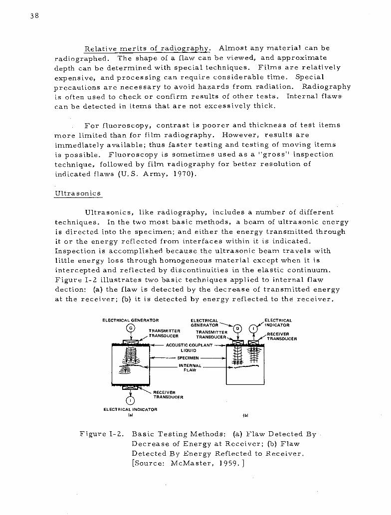
Ultrasonics
Ultrasonics, like radiography, includes a number of different
techniques. In the two most basic methods, a beam of ultrasonic energy
is directed into the specimen; and either the energy transmitted through
it or the energy reflected from interfaces within it is indicated.
Inspection is accomplished because the ultrasonic beam travels with
little energy loss through homogeneous material except when it is
intercepted and reflected by discontinuities in the elastic continuum.
Figure I-2 illustrates two basic techniques applied to internal flaw
dection: (a) the flaw is detected by the decrease of transmitted energy
at the receiver; (b) it is detected by energy reflected to the receiver.
ELECTRICAL GENERATOR ELECTRICAL ELECTRICAL
G GENERATOR ~(~ ( INDICATOR
TRANSDUCER TRANSDUCER RANSUCER
ACOUSTIC COUPLANT -
LIQUID
SPECIMEN
INTERNALFLAW
RECEIVERTRANSDUCER
ELECTRICAL INDICATOR
(a) (b)
Figure 1-2. Basic Testing Methods: (a) Flaw Detected By
Decrease of Energy at Receiver; (b) Flaw
Detected By Energy Reflected to Receiver.
[Source: McMaster, 1959.]

39
Relative merits of ultrasonics. Ultrasonics is a valuableinspection means for testing smooth-surfaced, fine-grained materials,especially steel and aluminum products. Considerable thicknesses canbe tested from any accessible surface; however, liquid couplants arerequired between the test item and test instrument transducer. Itemscan be tested with oil-type couplants or immersed in water. Flawlocation and depth can be approximately determined, and automation iscommon. Complex-shaped test items are sometimes impossible totest adequately, as are rough surfaces, large-grained materials andfiber-reinforced composites. Some items must be tested from variousdirections to insure that flaws oriented in all directions are detected.The principal advantages are that fine cracks a considerable distancefrom the transducer can be detected, and results are immediatelyavailable (U.S. Army, 1970).
Liquid Penetrant
Penetrant inspection is one of the simplest and most commonlyused NDT techniques. Figure I-3 illustrates the principle involved.
Relative merits of liquid penetrant inspection. This method canbe used to test practically any material regardless of physical char-acteristics and geometry. It can also be used as a leak test by checkingthe opposite side of a test item for bleed-through of the penetrant. 'Thistechnique is limited to surface cracks only and requires a clean surfacefree of contaminants. Furthermore, penetrant removal after a test canbe problematic (U.S. Army, 1970).
Magnetic Particle
Like liquid penetrant inspection, magnetic particle techniquesare relatively easy and simple to use. They are almost completelyfree from any restrictions as to size, shape, composition, and heattreatment, as long as a part can be magnetized. There are essentiallythree basic steps in using the technique:
1. Establish a suitable magnetic field in the test object.
2. Apply magnetic particle to the surface of the object.
3. Examine the test object for accumulation of the particlesand interpret the pattern.

Following Application, Liquid Penetranton Surface Seeps into Crack.
Water Spray Removes Penetrant From SurfaceBut Not From Cracks and Pores.
A\d N X,,<
Developer Acts as a Blotter toDraw Penetrent from Crack.
Black Inspection Light Causes FluorescentPenetrant to Glow in Dark.
Figure I-3. Liquid Penetrant Inspection. [Source: McMaster, 1959. ]
40

41
A crack in a part distorts the magnetic lines of force andcreates poles on either side of the crack, thus causing a buildup of
particles. Figure I-4 illustrates the phenomena for a crack in a bar
magnetic.
MAGNETIC PARTICLES
I "
iu-- A4- C cRs
CRACK-\
Figure 1-4. A Crack in a Bar Magnet Creates Magnetic Poles
Which Attract Magnetic Particles. [Source:
McMaster, 1959.]
Relative merits of magnetic particle inspection. Magnetic
particles can be used to detect almost all kinds of surface flaws as well
as those just below the surface. Surface plating and/or contamination
does not greatly affect results, as it does with liquid penetrants. This
technique can only be used on ferromagnetic materials, and parts must
be demagnetized after the test (U.S. Army, 1970).
Eddy Current
Within the broad spectrum of electronic test methods involving
the interaction of magnetic fields and circulating currents, the most
widely applied technique is eddy current testing. Eddy currents are
induced in a test item by means of coils carrying high frequency
AC current. Special instruments identify flaws by detecting distortions
in the resulting magnetic fields.
Relative merits of eddy current testing. This method is capable
of inspecting large quantities rapidly and is easily adapted to automation.
Nonmetallic contaminants do not affect results significantly. Testing
speeds can be high because of the inherently high exciting frequencies,
and direct contact with the test item is not required.

42
Eddy currents can be used on electrically conductive materialonly. The method is sensitive to geometry and limited to simple shapes,unless complicated scanning systems are employed. Quantitative assess-ment of flaw shape and size is difficult to make (U.S. Army, 1970).

PRECEDING PAGESBLANK NOT FILMED
ATTACHMENT II
SELECTED NDT DEVELOPMENTS THAT HAVE RESULTED
FROM NASA-SPONSORED RESEARCH
The field of nondestructive testing is extensive both in its tech-
nological dimensions and its applications. Sections I and II have pro-
vided an indication of the breadth of the NDT field, along with the
pervasiveness of NASA contributions to the field. This attachment, by
contrast, focuses on three specific innovations to provide an in-depth
look at selected NASA contributions. The nondestructive spot test, the
solid state image amplifier, and the ultrasonic Delta technique have
been chosen for special investigation because of their relation to the
trends discussed in Section II, as well as for their technological
significance.
Chemical Spot Test
The need for a reliable system to rapidly identify incoming
raw materials provided a NASA Langley Research Center innovator
with the impetus for development of a chemical spot test. Since com-
position of materials is fundamental to the ultimate utility of fabricated
parts, raw materials are commonly inspected for conformance to
engineering specifications. Furthermore, the selection of subsequent
machining and joining procedures is integrally dependent upon knowledge
of material properties.
The spot test technique developed by NASA applies the principles
of qualitative chemical analysis to identify metals and alloys. 'Groups of
substances are first isolated, then split into subgroups, fractions of
subgroups, and finally a single metal or alloy. The information is
presented in flow chart form as illustrated in Figure II-1.
Tests are performed by adding a few drops of a test reagent to
an extremely small particle of the unknown material. Conclusions
relative to identification of the unknown are drawn from the resulting,
unique reactions to the reagents. These reactions are manifested as
distinct color changes, which are produced when the appearance or
disappearance of phases and their boundaries cause changes in the
absorption of light. Although all tests are qualitative, semiquantitative
conclusions can be drawn by conducting simultaneous tests on a speci-
men with known chemical composition.

46
CHART 1
aUNKNOWN
Magnetic Test
Magnetic
Carbon steelLow alloy steelTool steel400 series S.S.17-4 PH
MonelNickel"D" nickel"TD" nickelHypernom
1 Drop 1:1 Nitric AcidObserve After 5 Minutes
Slightly Magnetic
Cold worked 301,AM 350, 17-7 PH
Follow Chart 5
Brown Color Clear Drop, Brassy CoatingBlack Ring Clear or Pale
Green DropCarbon steelLow alloy steel High tungsten,Drill rod Molybdenum, NickelBrown and Sharpe Cobalt, or "D" nickelSpring steel Vanadium "TD" nickelKetos steel Tool Steel
I I IFollow Chart 2 Identify by Follow Chart 2
tests
NonmagneticI
Follow Chart 5
No reaction
400 series S.S.17-4 PH
Follow Chart 4
Bright Green Clear DropI Blue-Green Ring
Add 1 dropconcentrated Allow to reactammonium 5 min longerhydroxide
I Blue ringBlue color
Add 1 drop 10%± Monel potassium thio-cyanate solution
Blood red color
I".er om
Figure II-1. Identification of Metals and Alloys Using the Procedure
Outlined in the Technical Support Package for Tech Brief
70-10520. [Source: Wilson, 1970. ]
300 series S.S. Inconel 600 Tantalum Tin17-7 PH Inconel 625 Niobium B66 ZincAM 350 Inconel 750 Silver Lead21-6-9 Molybdenum Indium Vanadium20-Cb Tungsten CadmiumRene 41 Aluminum and aluminum alloysNichrome V Magnesium and magnesium alloysHastelloy X Copper and copper alloysNonmagnetic monel Titanium and titanium alloys
I I

47
The use of qualitative chemical analysis to determine the com-
position of unknown materials is not new. However, the chemical spot
test developed by NASA is noteworthy because of two contributions. It
first reflects a fundamental effort in aggregation of previously frag-
mented information. The information is presented in a compact, useable,
form that requires no special skills for implementation. Second, a
refined capability to accurately identify alloys is reflected in many of
the tests.
The significance of the NASA contribution can be best described
by a single word--practical. The myriad of applications for identifica-
tion of unknown materials include receiving inspection, periodic
inventory checksi separation of mixed lots, tracing misidentified parts,
periodic checks of parts in process, and field identification of critical
components. All of these applications require a quick and inexpensive
means for materials identification. Spectroscopic analysis generally
requires a laboratory environment, expensive equipment and skilled
operators. The chemical spot test developed by NASA, however, has
many features which illustrate its usefulness:
* Low cost. A complete kit including equipment and reagents
costs less than $500. Test time required to identify an unknownmetal is less than 30 minutes.
* Easy to use. A master kit can be completely portable for on-line
or on-site testing. No special training or expertise is requiredto perform tests.
* Comprehensive. The procedures cover all common metallurgical
elements--aluminum, copper,, magnesium, nickel, titanium
and steel. Over 150 metals and alloys can be accuratelyidentified.
· Nondestructive. Tests can be performed on a small area of a
part or on an amount of metal equivalent to that removed by asingle stroke of a smooth file.
Information on the technology transfer activity associated with the NDTspot test is presented in the "NDT Spot Test for Metal Identification"
Transfer Example Summary in Attachment IV.

48
Solid State Radiographic Image Amplifier
As evidenced by its popularity, radiography is an extremely
important and powerful nondestructive testing tool. However, becauseit is one of the oldest NDT techniques and its limitations have becometraditional, radiography has entered a state of maturity, which is char-acterized by a modest growth rate when compared to other NDT tech-niques. Ultrasonics, for example, is expected to grow more rapidlybecause it offers advantages such as portability, rapid results, safetyto personnel and low cost operation. Thermal and infrared techniquesfeature inexpensive real time testing. Furthermore, this pattern istypical of other growing techniques in the nondestructive testing field.Undoubtedly then, any rejuvenation of radiography can only be accom-plished by technological innovations which provide these kinds of traits.
The NASA-developed, solid state radiographic image amplifier
is just such an innovation. This device converts input radiation into anelectric current, amplifies the current, and then excites an electro-luminescent material to form an image on a flat, lightweight panel.The image obtained is comparable in quality to that achieved usingradiographic film. When permanent records are desired, the image
can be photographed. This unique development promises to removethe burdensome weight of film processing from the shoulders of radio-graphic techniques, and thereby open up an entirely new horizon ofapplications.
Principle of operation. Fundamentally, the image amplifieremploys a photoconductive (PC) layer and an adjacent electroluminescent(EL) layer in a sandwich configuration. The rather unique properties
of PC and EL materials provide the basis of operation for the radio-graphic image amplifier. Photoconductive materials exhibit an increase
in electrical conductivity when they absorb electromagnetic radiation(X-rays for example), whereas, electroluminescent materials emitlight upon the application of an electric field.
Figure 11-2 illustrates the basic electronic circuit for a PC-ELdisplay. An AC voltage is applied across the series-connected PC and
EL elements. This voltage is divided between the elements accordingto their impedance ratio. In the unexcited condition the PC's voltage
is high because its resistance is high. This condition causes thevoltage across the EL to be low and thereby produces a very low light
output. When the PC is exposed to electromagnetic radiation, however,

49
its resistance decreases, the voltage across the EL element rises, anda light pattern (B out) of the input energy (X inp) is produced.
Figure II-2. Basic Circuit of PC-EL Type Light Intensifiers.[Source: Szepesi, 1969.]
A continuous-layer, sandwich-type construction has beendemonstrated to be the best way to fabricate solid-state imageintensifiers (Szepesi, 1971). Several options are available, dependingon performance and application requirements. Because of a radiation

50
hazard to personnel, NASA's primary area of interest has been
directed to image storage panels. Storage panels can be irradiated
while test personnel are located in a safe area, then studied after the
radiation source is de-energized. Nonstorage panels are illuminated
only during exposure to radioactive energy sources, requiring a lead
glass view port and shielding.
Construction of the storage panel is illustrated in Figure II-3.
The function of each layer is further discussed:
* Glass substrate. The glass serves as the foundation upon which
subsequent layers are assembled.
* Tin-oxide coating. The glass is coated with tin-oxide to provide
electrical contact with the EL material.
* Electroluminescent material. The EL layer is embedded in
a high-dielectric constant plastic and sprayed onto the coated
glass. The thickness of the EL layer is between one and twothousandths of an inch.
* Photoconducting layer (ZnO). A plastic embedded zinc-oxide
layer is bladed on the EL layer. Typical thicknesses range
between eight and ten thousandths of an inch. The fine-grained
ZnO powders have excellent storage properties and are capable
of reproducing half-tones.
* Gold (Au) electrode. A gold film is evaporated on the PC layerto facilitate electrical lead wire attachment.
To summarize, incident radiation causes increased electrical
current flow in a photoconducting material. This current is used to
excite an electroluminescent material and thereby produce an illuminatedimage of the radiation energy pattern. Incident electromagnetic energy
is converted into a light output suitable for viewing. Proper selection
of optoelectronic characteristics of the PC and EL materials produces
amplification of the input energy.

X-r
,/ # /' I
Light Output
NMI ---
ray/ Au Electrode Zn 0 Layer
.t EL Layer-w ~~Wir re Lead
K Tin-Oxide Coating
Glass Substrate
b.
Iead to Top ElectrodeLead to Top Electrode
\Lead to Tin-Oxide Left Border
(a) CROSS SECTION
Figure 11-3.
Lead to Tin-Oxide Right Border
(b) TOP VIEW
Construction of Storage Radiographic Amplifier
Screens on Glass Substrates. [Source: Szepesi,
1969. ]
NASA technological contribution. Interest in direct imaging
and image amplification is probably nearly as old as radiography itself;
however, the history of the PC-EL sandwich-type panel traces back
to 1952, when a German scientist, Dr. Stiirmer, applied for the first
patent related to the subject. The German patent application was
quickly followed by three others (an Australian and two American
applications) in the same year. Since then over a hundred patents
proposing a large variety of construction techniques, materials, and
applications have been awarded (Szepesi, 1969).
51
Wire Lead
1k ra.
c~~~c~~rr)- rr~~~~~~l

52
Because of serious limitations in available materials, these
devices remained primarily a laboratory curiosity for almost 17 years.
The requirement of high PC-EL capacitance ratio was primarily
responsible for stunting the growth of direct image amplifiers. Thus,
the commercial availability of high-dielectric constant plastics repre-
sented a truly significant break-through in the development of solid
state image intensifiers.
NASA's interest in the concept began shortly after the discovery
of the high-dielectric constant plastics. The NASA role can be best
summarized as that of bringing the PC-EL imaging concept from a
laboratory curiosity to a useful engineering tool. The work was per-
formed by the Westinghouse Electronic Tube Division under direction
of engineers at Marshall Space Flight Center. Table II-1 illustrates
the performance improvements that have been realized during the
NASA/Westinghouse program.
TABLE II-1. SOLID STATE IMAGE AMPLIFIER PERFORMANCEIMPROVEMENTS RESULTING FROM NASA
DEVELOPMENT EFFORTS*
PERFORMANCE PARAMETER STATE-OF-THE-ARTBefore NASA After NASA
Resolution 40 lines/inch 300 lines/inch
Contrast 8-10% 2%
Luminous Gain 1 100
Brightness 3-4X
* Source: Brown, 1971.
NASA's concentration of effort directed to radiographic
applications is of noteworthy significance, since most other develop-
ment efforts have been aimed at amplifying input light energy. Early
attempts to develop radiographic intensifier panels fell short because
of the numerous, conflicting performance demands. However, by
cascading two panels, each of which satisfies a group of requirements,
all the requirements could be met. One panel features high contrast

53
and sensitivity along, with fast rise time, while a second panel is
addressed to the requirements of storage and fast erasure-time.
Furthermore, cascading of panels significantly reduces the X-ray
exposure required for suitable image production. For example, acombined basic PC-EL panel with a light sensitive Thorn panel-*
requires only 1/350 of the X-ray intensity of a single PC-EL panel.
Applications for the radiographic image amplifier. Continueddevelopment of the solid state image amplifier is being pursued by
Westinghouse for numerous commercial applications. Among theseapplications are industrial radiography, where film costs can be
significant; medical radiography, where, as in mobile X-ray units,rapid interpretation and reduced exposure are desirable; and veterinary
applications, where portability of equipment is imperative for on-sitediagnosis. Additional information on the "Solid State Imaging Device"
is presented in a Transfer Example Summary in Attachment IV.
Ultrasonic Delta Technique
The many features offered by ultrasonic NDT are largelyresponsible for the intense and rapidly growing interest in this tech-
nique. Users of ultrasonics for flaw identification can employ inexpen-sive and portable equipment while realizing benefits such as rapid
testing, immediate test results and high sensitivity. Furthermore, the
method is not limited by material.thickness and is suited to automatedprocessing applications.
Even with these advantages, ultrasonic techniques fall short of
becoming the universal NDT tool. For example, evaluations utilizing
the traditional techniques of pulse-echo, angle beam, and shear wave
are limited to the detection of defects which lie in a preferred orienta-
tion. In addition, skilled operators are required; and also, permanent
records are not normally available. To overcome these limitations
Automation Industries, Incorporated developed an ultrasonic Delta
technique, which gets its name from the characteristic triangular
positions of the search units used to perform the tests. The outstanding
feature of the Delta technique is its ability to function regardless ofdefect orientation. Other ultrasonic methods, as well as radiographic
techniques, require the excitation energy to strike the flaw in a
* Manufactured by Thorn Electrical Industries, Enfield, England.

54
perpendicular or near perpendicular manner in order to obtain adefect signature. As a result, in many critical NDT applications,
inspection must be performed from two directions. The Delta technique
incorporates the advantages of ultrasonics, along with the added benefits
of rapid scanning, low cost testing and providing permanent records.The ability to acquire information on flaw characteristics without
concern over test orientation, however, represents the significantadvancement to the state-of-the-art.
Principle of operation. Ultrasonic NDT is based on the char-
acteristic of discontinuities to attenuate or scatter an ultrasonic wave
propagating through a material. An electromagnetic transducer first
generates sound waves ina part by converting electrical energy into
mechanical energy. The waves propagate without disturbance until
encountering a flaw or a test piece surface. Knowledge about a partallows reflections from flaws to be discriminated from surface reflec-
tions. A receiving transducer converts reflected acoustic energy into
electrical energy, thus facilitating observation of the event.
The Delta technique represents a departure from conventional
ultrasonic methods. Previously, ultrasonic systems were exclusively
interested in the primary mode of wave propagation; secondary modes
represented unwanted test signal noise. In contrast, the Delta technique
utilizes these secondary modes to obtain information about defect size
and orientation. Figure II-4 illustrates the fundamental principles of
the Delta technique. As with many emerging innovations, the develop-
ment and application of this technique has proceeded without a rigorous
mathematical proof of the concept.
An explanation of the Delta phenomena was developed from
classical energy equations and empirical laboratory data. To aid in
the analysis of the Delta phenomena certain terms have been defined:
* Transmitted Beam - The transmitted beam is the longitudinal
wave originating at the transmitter search unit and incident
upon the part surface at a specified angle.
* Transmitted Shear Beam - The transmitted shear beam is the
refracted shear wave propagating in the part as a result of the
transmitted beam striking the part surface. The angle of
incidence between the transmitted beam and the part surface is
beyond the critical angle for transmission of longitudinal energyinto the part.

Transmitter _Search Unit
Effect
Transmitted
(a)
\ Mode ConvertedLongitudinal Wave
Search Unit Relationship in the Basic Delta Configuration.
(b)
Figure II-4. Fundamental Principles of the Delta Technique.
[Source: Hannah, 1968. ]
55

/ 56
* Interface - The surface forming the boundary between two
adjacent media of different acoustical impedance is the interface.
* Redirected Energy - Any energy propagating in the part in a
direction different from that of the transmitted shear beam is
redirected energy. Redirection is caused by an interaction
between the transmitted shear beam and an interface. Redirected
energy can be reflected, mode converted or reradiated energy.
* Mode Conversion - Mode conversion is the change of ultrasonic
energy from one mode of propagation to another as a result of
striking an interface. Ultrasonic energy will propagate in an
elastic media in three principle modes: longitudinal, shear and
surface.
* Reradiated Energy - An omnidirectional, coherent ultrasonic
wave generated at an interface as a result of interface excitation
caused by an impinging ultrasonic beam is reradiated energy.
When the transmitted beam strikes an interface it can split into
three distinct modes of redirected energy. All three types are used
for flaw detection: (1) a reflection of the transmitted shear beam, (2) a
mode-converted longitudinal beam, and (3) a reradiated sound beam.
The net result of these modes of propagation is a fanlike redirection
of the transmitted sound beam. This fanlike spray of redirected
energy minimizes the influence of flaw orientation.
In summary, the Delta technique ultrasonically illuminates a
part in one direction and views it from another direction. A defect in
the part acts as an energy reradiator similar to the way radar signals
are reradiated from a flying aircraft (Posakony, 1971).
History of development. A brief review of the history of the
development of the Delta technique is presented for two reasons. First,
it illustrates the multi-organizational interest in the phenomena; and
second, it sets the stage for delineating NASA's contribution to the
overall development.
Interest in the technique grew out of the inability of conventional
ultrasonics to detect randomly oriented defects. This shortcoming led
to an in-house investigation of the technique by Automation Industries,
Incorporated. The discovery that the Delta phenomena produced far

57
more information than conventional ultrasonic systems led to extensive
research work aimed at understanding the physics of the phenomena
and improving the capabilities of the technique. From the original
application to flat plates, the technique was then applied to weldments.
Feasibility of the technique for weld inspection was established under a
program performed for the Martin Marietta Corporation. This work
was followed by three Air Force contracts for the development of an
ultrasonic system to provide isometric views of defects in metals and
welds, as well as correlate the three-dimensional ultrasonic scanning
system with standard immersion techniques. A lack of definition of
certain types of defects, especially when Delta results were compared
to radiographs, led to an additional research study sponsored by the
Bureau of Ships. The objective of the program was to study the physics
of sound energy as it propagates into a weld specimen and determine
the directions of the redirected energy. This information was then
used to refine the Delta method (Posakony, 1966).
Up to this point, engineering effort on the Delta phenomena
was appropriately confined to laboratory investigation. This activity
set the stage for NASA's entrance into the evolving Delta development.
Faced with one of the greatest technical. challenges of the space
program--the need to detect tight lack of penetration (LOP) in welds--
NASA turned to the Delta technique for a solution. The problem
occurred where weld passes made on each side of joined parts did not
penetrate sufficiently to completely fuse the parts. The difficulty
arose because shrinkage stresses caused the edges of the plates to
become so tightly abutted that radiography and conventional ultrasonics
could not detect the flaw. The problem was ultimately solved using opaque
additives on the edges of the plates and thereby enhancing the LOP in
radiographic images. Nevertheless, Marshall Space Flight Center con-
tinued with the development of the Delta technique for other applications
because it had demonstrated a significant improvement over conventional
ultrasonics (Neuschaefer, 1969).
NASA contribution. The NASA contribution to the overall
development was to transform the Delta technique from a laboratory
tool into a reliable inspection method for production weld evaluation.
A development program was performed in two phases: the first was
directed to an analytical and empirical study of the Delta phenomena for
aluminum alloys, combined with a test and evaluation program to estab-
lish Delta operating parameters for these alloys. The second phase,
included the design, fabrication, and evaluation of a Delta wheel and
manual Delta probe for inspecting aluminum butt welds.

58
Tests demonstrated that the Delta technique successfully
detected weld defects of primary concern in 2014 and 2219 aluminum
alloy weldments at inspection rates of 50 feet per hour. Results of this
study are summarized in Table II-1, As the table illustrates, sub-
stantial improvements in test method reliability were demonstrated for
all flaw types, but especially for lack of penetration, lack of fusion
and microfissure defects.
TABLE II-I. COMPARISON OF OVERALL NDT RESULTS*
Conventional Ultrasonic
Delta Inspection 60' Angle Beam RadiographyCorrelation With Correlation With Correlation With
Flaw Types Destructive Tests Destructive Tests Destructive Tests
Lack of Penetration 73% 50% 37%
Lack of Fusion 98% 45% 84%
Porosity > 0.010" 92% 100% 83%/0
Porosity < 0. 010" 49 17%o 37%
Cracks 90% 75% 60%
Micro-fissuring 100%o 0% 14%
*Source: Hannah, 1968.
Significance of the Delta technique. The Delta technique
represents added capabilities to NDT technology in two significant ways.
First, the method works regardless of flaw orientation, resulting in
lower cost, and a faster, more reliable ultrasonic inspection is
achieved. Second, the phenomena have the potential to completely
characterize a defect. Ultimately an ultrasonic picture can be made
from an insonrified** part. From this picture, defect characteristics
such as size, shape, and type can be determined. This information
would then allow a determination of the critical nature of a flaw as
well as facilitate predictions of remaining service life. Transfer
activity associated with the technology is discussed in the "Ultrasonic
Delta Technique" Transfer Example Summary in Attachment IV.
** Insonify is a coined word which indicates the dosage of ultrasonic
energy. It is comparable to the level of intensity of radiation in
radiographic testing.

PRECEDING PAGSBLAN NOT FILMED
ATTACHMENT III
TECH BRIEF EXHIBIT
Technical Tech Brief Tech Brief
Category Number T itle
Ultrasonics 66-10178
66-10220
66- 10289
66- 10544
66-10577
67-10127
67-10428
67-10486
67-10542
67-10620
68-10004
68- 1-0379
69- 10402
.69-1040470-10055
70-10118
70- 10397
70- 10514
Fatigue Cracks Detected and Measured
Without Test Interruption
Ultrasonic Recording Scanner Used for
Nondestructive Weld Inspection
Ultrasonic Hand Tool Allows Convenient
Scanning of Spot Welds
Ultrasonic Quality Inspection of Bonded
Honeycomb Assemblies is Automated
Ultrasonic Water Column Probe Speeds
Up Testing of Welds
Calibrating Ultrasonic Test Equipment
for Checking Thin Metal Strip Stock
Ultrasonics Used to Measure Residual
Stress
Ultrasonic Hand Tool Allows Convenient
Diagnostic Scanning of Bone Integrity
Plastic Shoe Facilitates Ultrasonic
Insp.ection of Thin Wall Metal Tubing
.Ballpoint Probe Gives Optimum Results
in Ultrasonic Testing
Development of Mechanized Ultrasonic
Scanning System
Automatic System Nondestructively
Monitors and Records Fatigue Crack
Growth
Nondestructive Testing of Welds on
Thin-Walled Tubing
Generation of Sonic Power During Welding
Immersed Ultrasonic Inspection of High
Acoustical Attenuative Structures
Acoustic Vibration. Test Detects Inter-
mittent Electrical Discontinuities
Nondestructive Sonic Testing of Adhesive-
Bonded Composites
Ultrasonic Detection of Flaws in Fusion
Butt Welds
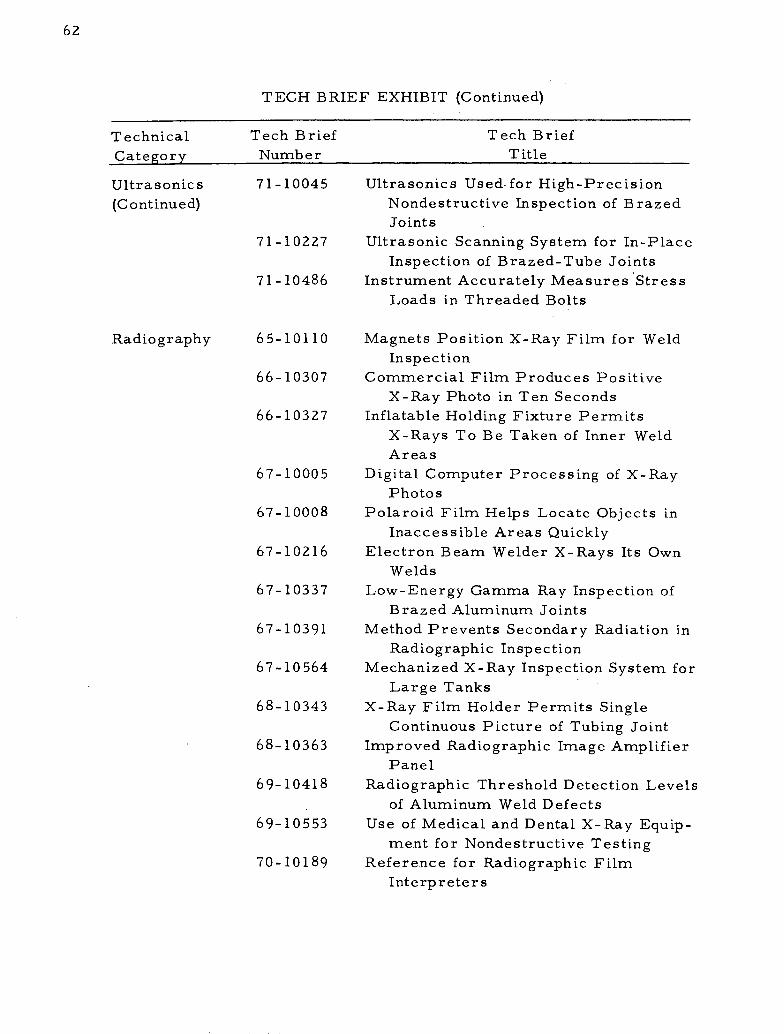
62
TECH BRIEF EXHIBIT (Continued)
Technical Tech Brief Tech Brief
Category Number Title
Ultrasonics
(Continued)
71-10045
71-10227
71- 10486
Radiography 65-10110
66- 10307
66-10327
67- 10005
67- 10008
67- 10216
67- 10337
67- 10391
67- 10564
68- 10343
68- 10363
69-10418
69-10553
70-10189
Ultrasonics Used-for High-Precision
Nondestructive Inspection of Brazed
Joints
Ultrasonic Scanning System for In-Place
Inspection of Brazed-Tube Joints
Instrument Accurately Measures Stress
Loads in Threaded Bolts
Magnets Position X-Ray Film for Weld
Inspection
Commercial Film Produces Positive
X-Ray Photo in Ten Seconds
Inflatable Holding Fixture Permits
X-Rays To Be Taken of Inner Weld
Areas
Digital Computer Processing of X-Ray
Photos
Polaroid Film Helps Locate Objects in
Inaccessible Areas Quickly
Electron Beam Welder X-Rays Its Own
Welds
Low-Energy Gamma Ray Inspection of
Brazed Aluminum Joints
Method Prevents Secondary Radiation in
Radiographic Inspection
Mechanized X-Ray Inspection System for
Large Tanks
X-Ray Film Holder Permits Single
Continuous Picture of Tubing Joint
Improved Radiographic Image Amplifier
Panel
Radiographic Threshold Detection Levels
of Aluminum Weld Defects
Use of Medical and Dental X-Ray Equip-
ment for Nondestructive Testing
Reference for Radiographic Film
Interpreters

63
TECH BRIEF EXHIBIT (Continued)
Technical Tech Brief Tech Brief
Category Number T itle
Radiography
(Continued)
71-10206
71-10226
71-10438
71-10439
71-10492
Chemical and
Spectrographic
Analysis
66-10305
70-10057
70- 10402
70-10471
70- 10520
70-10661
71-10009
71 -10359
Interpretation of Aluminum-Alloy Weld
Radiography
Multilayered Printed Circuit Boards
Inspected by X-Ray Laminography
Radiographic Inspection Specifications
for Electronic Components
A Multiple-Plate, Multiple-Pinhold
Camera for X-ray and y-ray Imaging
Optimized Techniques and Requirements
for Computer Improvement of
Structural Weld Radiographs
Simple, Nonstructive Test Identifies
Metals
Mass Spectrometer Detects HighMolecular Weight Components
Improved Photoionization MassSpectrometer
Apparatus for Simultaneous Ion Counting
and Current Recording in Mass
Spectrometry
Nondestructive Spot Tests Allow Rapid
Identification of Metals
Spectral Emission Measurement of
Igneous Rocks Using a
Spectroradiometer
Fast Peak Selector for Mass
Spectrometer
Simplified Procedure for Emission
Spectrochemical Analysis
Other Non-
destructive
Testing
Techniques
65-10107
65-10265
66- 10028
Crack Detection Method is Safe in
Presence of Liquid Oxygen
Weld Leaks Rapidly and Safely DetectedPortable Self-Powered Device Detects
Internal Flaws in Tubular Structures

64
TECH BRIEF EXHIBIT (Continued)
Technical Tech Brief Tech Brief
Category Number Title
Other Non-
destructive
Testing
Techniques
(C ont inued)
66- 10131
66-10341
66-10574
66- 10587
66-10652
67-10116
67- 10121
67-10286
67- 10333
67- 10403
67-10430
67- 1043167-10482
67-10645
68-10002
68-10021
68-10183
68-10246
68- 10333
Surfactant for Dye-Penetrant Inspection
Is Insensitive to Liquid Oxygen
Ultrasonic Emission Method Enables
Testing of Adhesive Bonds
Nondestructive Test Method Accurately
Sorts Mixed Bolts
Quality Control Criteria for Acceptance
Testing of Cross-Wire Welds
Rocket Engine Vibration Accurately
Measured by Photography
Detection of Entrapped Moisture in
Honeycomb Sandwich Structures
Portable Fixture Facilitates Pressure
Testing of Instrumentation Fittings
Liquid Crystals Detect Voids in Fiber-
glass Laminates
Braze Joint Quality Tested Electro-
magnetically
Wear Studies Made of Slip Rings and
Gas Bearing Components
Study Made of Acoustical Monitoring for
Mechanical Checkout
Camera Lens Adapter Magnifies Image
Surface-Crack Detection by Microwave
Methods
Eddy Current Probe Measures Size of
Cracks in Nonmetallic Materials
Gage Monitors Quality of Cross-Wire
Resistance Welds
Optical System Facilitates Inspection
of Printed Circuit Boards
Detection and Location of Metallic
Objects Imbedded in Nonmetallic
Structures
Miniature Pressure Transducer for
Stressed Member Application
Automatic, Nondestructive Test Monitors
In-Process Weld Quality

65
TECH BRIEF EXHIBIT (Continued)
Technical Tech Brief Tech Brief
Category Number Title
Other Non-destructiveTestingTechniques(Continued)
68-10347
68-10364
68- 10378
68-1051169- 10059
69-10142
69-10152
69-10226
69-10464
69- 10663
69-10700
69-10756
70-10012
70- 10027
70- 10033
70-10084
70- 10123
Improvement in Recording and Reading
Holograms
Nondestructive Test Determines Over-
load Destruction Characteristics of
Current Limiter Fuses
Nondestructive Method for Measuring
Residual Stresses in Metals, a Concept
Rocket Engine Analog Simulation
Reidentifying Hardware After Loss of
Serial Number
Improved Combustion Chamber Optical
Probe
Surface Irregularities Detected by
Flare Inspection Instrument
Camera Mount for Close-Up Stereo
Photographs
Nondestructive Determination of
Cohesive Strength of Adhesive-Bonded
Composites
Fine-Line Sensitivity for Holographic
Interferograms
Long Range Holographic Contour Mapping
Concept
Seismographic Recording of Large
Rocket Engine Operation
Sonic Impedance Technique Detects
Flaws in Polyurethane Foam Spray-On
Insulation
A Method for the Visual Detection of
Holes in Thin Polymeric Films
A Simple Tester Provides Resonant
Frequency Measurements of FerriteDevices
Electrical Resistance Determination of
Actual Contact Area of Cold Welded
Metal Joints
Holographic Stress Analysis

66
TECH BRIEF EXHIBIT (Continued)
Technical Tech Brief Tech BriefCategory Number Title.
Other Non-destructiveTestingTechniques(Continued)
70-10215
70-10263
70-10266
70- 1029270-10326
70- 10466
70- 10533
70- 10630
70-1065470- 1071671- 10021
71- 10022
71-10103
71 -10129
71-1019471-10208
71- 10258
71 -10452
Inorganic Bonding of SemiconductorStrain Gages
A Proposed Laser MeasurementSystem for Determining SurfaceContour
Motor Brush Wear Measured with StrainGages
Noncontacting-Optical-Strain DeviceStrain Gage Load Measuring Device:
A ConceptNondestructive Assessment of
Penetration of Electron-Beam WeldsElectronic Flaw Simulator for Eddy
Current Probe CalibrationBonding of Strain Gages to Fiber
Reinforced Composite PlasticMaterials
Holographic Analysis of Thin FilmsElectronic Strain-Level CounterStudy of Second Breakdown in Power
Transistors Using Infrared TechniquesDesign and Development of a Fast Scan
Infrared Detection and MeasurementInstrument
Methyl Alcohol Used as PenetrantInspection Medium for PorousMaterials
Locating Tube Blockage That X-RayCannot Detect
Predicting Service Life MarginsNondestructive Testing of Adhesive
Bonds by Nuclear QuadrupoleResonance Method
Study of Nondestructive Techniques forRedundancy Verification
Precision, Triple-Parameter, Non-destructive-Test System forIn-Process Microwelding

67
TECH BRIEF EXHIBIT (Continued)
Technical Tech Brief Tech Brief
Category Number Title
Other Non-
destructive
Testing
Techniques
(Continued)
71-10507
71-10513
71-10534
General
Handbooks
67- 10195
67- 10374
67- 10533
67-10574
68- 10391
68-10394
69- 10108
69- 10278
69- 10366
69- 10730
70-10715
71- 10156
71- 10271
Nondestructive Testing of Bond
Integrity in Foam Insulation/
Aluminum Composites
Optical Inspection Tool for Interior
Surfaces of Fluid Lines
Multifrequency Laser Beams for
Holographic Contouring
Weld Procedure Produces Quality Welds
for Thick Sections of Hastelloy-X
Handbooks Describe Eddy Current Tech-
niques Used in Nondestructive Testing
of Metal Parts and Components
Study of Stress Corrosion in Aluminum
Alloys
Nondestructive Testing Techniques Used
in Analysis of Honeycomb Structure
Bond Strength
Training Manuals for Nondestructive
Testing Using Magnetic Particles
Nondestructive Testing of Brazed RocketEngine Components
Handbooks for Nondestructive Testing
Using Ultrasonics
Instruction Manuals for Liquid Penetrant
Nondestructive Testing
Instrumentation for Nondestructive
Testing of Composite Honeycomb
Materials
Effects of High-Pressure Hydrogen on
Storage Vessel Materials
Strain Gage Installation Manual
Instruction Manuals for Radiographic
Nondestructive Testing
Qualifications and Certification of
Nondestructive Testing Personnel
., . .A. .

ATTACHMENT IV
Summaries of Technology Transfer Reports InvolvingNASA-Generated Nondestructive Testing Technology
,. :1IprB \: ' . 1. IIpreceding page blank I
;" "
''. {,I

70
SUMMARY OF TECHNOLOGY TRANSFER REPORTS INVOLVING
NASA-GENERATED NONDESTRUCTIVE TESTING TECHNOLOGY
TRANSFER STAGES
NASA 1 2 3 4
CONTRIBUTIONS Cont.* Term. Cont. Term. Cont. Term. Cont. Term.
ULTRASONICS
· Mechanized UltrasonicScanning System
· Ultrasonic Delta TechniqueUltrasonic Hand Tool
· Ultrasonic Measurement
of Residual Stress
RADIOGRAPHY
* Radiographic FilmReference
* Solid State ImagingDevice
CHEMICAL AND SPECTRO-
GRAPHIC ANALYSIS
* NDT Spot Test ForMetal Identification
21897**54934
592011513931840
49702
21588 2050158901
44538
4463644768
4501047012
47074477444888066874
OTHER NONDESTRUCTIVE
TESTING TECHNIQUES
* NDT Measurement ofResidual Stress
* 1966 Nondestructive
Testing Symposium
* Fiber Optics DetectSurface Irregularities
* Optical Strain
Measuring Device* Sonic Impedance NDT
· Infrared Scanner for
Nondestructive Testing
2710654932
26855 26854
56301
5630257802
57803
30502
53850
48782
57574
GENERAL HANDBOOKS
· Nondestructive TestingManuals
* Nondestructive Testing
of Brazed Components· Nondestructive Testing
5170
6706
27624276342764227744
31534
4062253789
24833
70001
53871
2434227305
of Honeycomb Structures 4303
* Strain Gage Installation 51572
Manual 5195052304
* The action status, continuing or terminated, of transfer cases at the time DRI-PATT contacted
users. Cases are classed as terminated when (a) no further adaptation or adoption is contemplated,
(b) a better technical alternative has been found, or (c) continued transfer activity is not
economically feasible.
** Numbers in columns refer to PATT case numbers.

71
MECHANIZED ULTRASONIC SCANNING SYSTEM
TECHNOLOGY TRANSFER EXAMPLE SUMMARY
Nondestructive testing in the inspection of welds usually involves
X-ray or ultrasonic methods. In space vehicles, the range of material
thicknesses encountered limits the usefulness of radiography for detect-
ing lack-of-fusion and lack-of-penetration flaws. Using ultrasonics to
inspect the flaw content of welds in booster stages and propellant tanks
has been inhibited by the necessity of submerging the test weld in water
or providing a water flush over the inspection surface.
Raymond Evans and J. A. MacDonald of Marshall Space Flight
Center designed and developed a mechanized ultrasonic scanning
system, publicized in Tech Brief 68-10004. Their instrument is built
around a water column probe that eliminates the need for submerging
or flushing the test specimen. The probe is a transmitter and receiver
consisting of an ultrasonic transducer enclosed in a water filled cylinder.
The lower end of the cylinder is covered with a rubber diaphragm that
seals the unit and permits transmission of the ultrasonic beam to the
weld. The system consists of the probe, an ultrasonic flaw detection
unit, a recording unit, and special tooling to move the probe along the
inspection surface at a rate in excess of one inch per second.
The F. Yeager Bridge and Culvert Company in Port Huron,
Michigan (54934) plans to use the system as soon as better techniques
are developed for interpreting test results. The company fabricates
steel bridges for the Michigan Highway Department. The Department
currently requires X-ray testing of bridge welds because the results
may be interpreted objectively. The portability and recording features
of the ultrasonic scanner are attractive to Yeager Bridge; considerable
savings are anticipated from its use.
Engineers at De Laval Turbine, Incorporated in Trenton,
New Jersey (21897) have evaluated the system and found it to be satis-
factory for the company's needs if a suitable method or in-house

72
expertise can be developed to interpret the ultrasonic test results. A
company spokesman reported that the NASA system is potentially a more
efficient way to conduct quality control testing of De Laval's products
such as compressor wheels.
Control Numbers
Tech Brief Number: 68-10004
NASA Center: Marshall Space Flight Center
PATT Case Numbers: 21897, 54934
TEF Number: 380
Date of Latest Information Used: July 8, 1971

73
ULTRASONIC DELTA TECHNIQUE
TECHNOLOGY TRANSFER EXAMPLE SUMMARY -
Marshall Space Flight Center (MSFC) sought a nondestructive
testing technique to rapidly inspect butt welds in aluminum alloys and
detect the lack of weld penetration not readily seen in the radiographs.
With the increasing demands for high vehicle reliability, low cost,sensitive techniques, and automated testing, only a nondestructive test
system having exceptional capabilities could achieve the level of defect
detection required by MSFC. Since welding is an essential part of
fabrication of space vehicles, accurate nondestructive evaluation of
weldments requires use of the mostadvanced methods that are avail-
able. The Delta technique,, an ultrasonic weld inspection techniquedeveloped by the Research Division of Automation Industries,
Incorporated in Boulder, Colorado (59201), offered much promise for
accomplishing the weld inspection requirements of MSFC. This tech-
nique was developed to detect randomly oriented weld defects. In the
laboratory, the Delta technique had been used successfully for detecting
these defects. The company was awarded a NASA contract
(NAS 8-18009) in 1967 to transform the Delta technique from a labo-
ratory tool into a reliable inspection method- for production weldevaluation.
The Delta technique uses two or more transmitting transducers
which introduce ultrasonic sound energy into the material being investi-
gated at an angle that produces shear-wave energy in the material; for
welds it is introduced into the adjacent parent material. The soundpropagates in the material until it strikes an interface, which is any-
thing differing in acoustic impedance from the parent-material and
interrupting the propagation pattern of the sound beam. The interface
may be an inclusion, crack, or absence of weld penetration or fusion.
,At the interface the sound energy may be (1) simply reflected; (2) con-
verted in mode from shear to longitudinal; or (3) reradiated. Experi-
ments have shown the occurrence of this latter phenomenon; in concept
the defect acts as a new source of the sound energy. Any energy
redirected from the defect can provide information about the defect.
The energy received at the receiving search unit (RSU) conveys infor-
mation to either an oscilloscope or a printout about the defect, regard-
less of which path it followed to get there. The RSU is usually focused
for increase in the angle of capture of the redirected energy. In thinnermaterials the lengths of the various paths are so short that they give the

74
appearance of almost simultaneous occurrence; in thicker materialsthe various paths and modes can be separated and identified. Thenature and operation of two Delta configurations, the Delta Wheel andthe Delta Manipulator, are described in the TSP for Tech Brief70-10514.
The contracted development at Automation Industries producedan operational Delta technique and equipment which detected the weldflaws of primary concern in aluminum alloys at inspection rates of50 feet per hour and did so with greater accuracy than radiography.Destructive analysis of 18 feet of weldment tested showed that about80 percent of total defects were detected by the Delta technique, whereasonly 36 percent were caught by radiography.
Since the NASA contract was completed, Automation has beenproducing similar equipment for similar applications. Approximately25 companies have purchased the Delta Manipulators for $790.00 each.A single company may have as many as 100 of these units since theyare the key to using the Delta technique. NDT experts report that theDelta technique was immediately used to replace standard ultrasonicmethods in many applications as soon as the first descriptions of itsoperational capabilities were published (Automation's report in 1968,NASA CR-61952). Many users fabricated their own version of theManipulator for in-house use with standard transducers.
Control Numbers
Tech Brief Number: 70-10514NASA Center: Marshall Space Flight CenterPATT Case Number: 59201TEF Number: 387Date of Latest Information Used: August 9, 1971

75
ULTRASONIC HAND TOOL
TECHNOLOGY TRANSFER EXAMPLE SUMMARY
The Boeing Company, under contract to Marshall Space Flight
Center, has invented a portable, electrically-powered ultrasonic hand
tool for rapid scanning of spot weld discontinuities in small, inaccessible
places. The unit consists of an ultrasonic search unit attached to a
solenoid in a housing assembly which includes the scanning motor. The
solenoid is fitted with a recording stylus in contact with pressure
sensitive paper to provide a read-out of the results. In operation, the
front end of the scanner is placed on the area being examined. The
spiral scanning motion of the ultrasonic search unit is recorded as a
spiral pattern on the pressure sensitive paper. Weld discontinuities
will appear as breaks in the spiral pattern.
Moragne Machine and Manufacturing Corporation in Freeport,
Texas (15139) is using several copies of the hand tool, which were
fabricated in-house, to inspect welds on equipment produced by the
company for industrial use. Dr. Moragne, company president, has
used this and other NASA TSP's as the basis for an extensive investiga-
tion of ultrasonics. His investigation has produced several inventions:
a patented ultrasonic precipitator to clean air in the Houston Astrodome;
a carbon black plant and a fire brick plant; and a welding method in
which the work piece is vibrated ultrasonically to produce a superior
weld. Dr. Moragne attributes approximately $3. 5 million of increased
sales to his use of the NASA technology. This is, in part, indirect
since he includes all benefits which have evolved from his reading the
TSP.
Control Numbers
Tech Brief Number: 66-10289
NASA Center: Marshall Space Flight Center
PATT Case Number: 15139
TEF Number: 386
Date of Latest Information Used: July 12, 1971
/

77
ULTRASONIC MEASUREMENT OF RESIDUAL STRESS
TECHNOLOGY TRANSFER EXAMPLE SUMMARY
Metal machining and assembly processes can produce residualstress which can cause fatigue failure. Residual stress levels insidea metal are difficult to analyze, although surface residual stress can beanalyzed by X-rays, and dynamic surface stresses are observable
with strain gage and photostress techniques.
In 1967, R. W. Benson & Associates, Incorporated, undercontract to Marshall Space Flight Center, developed an ultrasonicmethod for stress analysis in which the patterns of wave propagation
inside the metal provide a basis for analysis. The method involvesmounting two Y-cut crystals with their axes of vibration at right angles.The crystals generate and receive signals, and the degree of stress inthe metal is revealed by timing the phase shift between the two signals.
Stresses within the metal can be measured with this method by varying
the signal frequency. The penetration depth of a surface wave isapproximately one wavelength, so that deeper penetration can beachieved by using lower frequencies. This method was described byNASA in Tech Brief 67-10428.
Lodding Engineering, a division of Thermo-Electron Corporationin Auburn, Massachusetts (31840), is proceeding with development ofa new product based on the Tech Brief. The firm's engineers had beenexperimenting with methods of nondestructively measuring residualstresses when they learned of the new technique. Visits to Marshall
convinced them that the principles embodied in the NASA technologycould be applied to a new product. Subsequent development workyielded two portable prototype instruments which work well on aluminumalloys but provide only qualitative data on ferrous alloys. The instru-ments give essentially instantaneous results under field conditions asopposed to at least an hour of preparation time for the strain gagetechniques. Although redesign efforts are underway to improve theinstrument's capability on ferrous alloys, the current model will bemarketed by June 1972 in the price range of $5, 000 to $10, 000.
Preceding page blank ]

78
Market prospects are quite good, and development costs willprobablybe recovered during the first year. The product is expected to replacethe use of strain gages in many applications.
Control Numbers
Tech Brief Number: 67-10428NASA Center: Marshall Space Flight CenterPATT Case Number: 31840TEF Number: 316Date of Latest Information Used: March 23, 1972

79
RADIOGRAPHIC FILM REFERENCE
TECHNOLOGY TRANSFER EXAMPLE SUMMARY
When radiography is used for nondestructive testing, the result-
ing image must be interpreted to discover flaws in the test object. An
improved "Reference for Radiographic Interpreters" (RRI) was compiled
at North American Rockwell Corporation under contract to Marshall
Space Flight Center. It provides a wider variety of X-ray film examples
for each weld defect than are available in other X-ray film references.
The RRI also contains examples of film quality, stainless steel weldedtubing and acceptable weld conditions. The film slides are one inch by
two inches and are contained in loose-leaf, celluloid folders for easy
viewing. The slides are identified by a number, which can then be
referenced to the summary sheet in the RRI for a detailed description
of the particular discrepancy shown on the film strip. An interpreter
who desired to familiarize himself with weld radiographs would view a
numbered X-ray slide and make an evaluation of the observed defects.
This evaluation would then be compared with the standard given in the
summary sheet for that particular slide. The RRI was announced by
NASA in Tech Brief 70-10189.
Quality control engineers at American Standards, Incorporated
in Franklin Park, Illinois (49702) frequently use the RRI to evaluate
X-rays of temperature sensors which are produced by the company.
Prior to receiving the NASA reference, this quality control evaluation
was based on less thorough references and required more time to
complete. The sensors are used by customers in boilers, reactors,
and laboratory equipment where safety requires a very stringent quality
control.
Control Numbers
Tech Brief Number: 70-10189
NASA Center: Marshall Space Flight Center
PATT Case Number: 49702
TEF Number: 382
Date of Latest Information Used: July 12, 1971

81
SOLID STATE IMAGING DEVICE
TECHNOLOGY TRANSFER EXAMPLE SUMMARY
The Electron Tube Division of Westinghouse Electric Corporationwas conducting research for the development of light amplification
panels when it was awarded a contract (NAS 8-21206) from MarshallSpace Flight Center in July 1967. The contract redirected this researchtoward radiographic amplification panels and supported the develop-
ment of working prototypes from the basic principles involved. One ofthese panels, together with a portable power pack and radio isotope
source, can provide a briefcase-sized X-ray unit. The image may bepreserved by photographing the panel display.
The new panel consists of a relatively simple, thin layeredconstruction. It provides images of higher contrast sensitivity and
better resolution over longer storage periods than are attainable with
previous image amplifiers of this general type. The device also
combines very high radiation sensitivity (10 milliroentgens, or less, of
penetrating radiation required for optimum display, compared to
350 milliroentgens for a "Thorne" image amplifier) with fast image
buildup and erasure capabilities. When excited by X-ray or gammaray radiation directed through a test specimen, the image amplifier
produces a daylight-visual image of the radiographic structural details
in its field of view. These characteristics are achieved by the addition
of two layers to a basic image amplifier and cascading this assembly
with a modified "Thorne" panel. The two new layers are connected
electrically in series. Radiation applied to the photoconductive layer
reduces its resistance, which decreases the voltage drop across it;
this increases the voltage across the electroluminescent layer causinga light pattern of the input energy to be produced. A Tech Brief was
issued in 1968, which described the current state of the panel's develop-ment. The basic configuration has not changed since then, although
considerable refinement has taken place.
The Westinghouse division, which is located in Elmira, New York(58901), has developed a potential new product as a result of the NASA
contract. The company has sold approximately 20 laboratory built
panels, worth a total of $20, 000, for evaluation in medical, welding and
other NDT applications. The invention appears to provide a significant
advance in radiography, and the company is conducting a promotional
campaign for commercial applications. If the panels are mass produced,
the quality will be improved, and the cost will be reduced by a factor as
great as 100.
Preceding page blank 7

82
Marshall has awarded two no-cost contracts for the develop-
ment and evaluation of medical applications for a portable X-ray unitwhich uses the panel. Tulane University Medical School in New Orleans,Louisiana and Southeastern State College in Durant, Oklahoma haveeach received one of the $400 units. The Tulane project, initiated byNASA's Biomedical Application Team (BATeam) at the ResearchTriangle Institute in Research Triangle Park, North Carolina, willutilize the panel to monitor cancer growth. The natural growth rate
will be minimally affected by the low radiation requirements of thepanel. The Southeastern State College project, initiated by NASA'sTechnology Use Studies Center, will develop the unit's applicationsfor veterinarians. The quick response and portability of the unit willbe used to X-ray large animals in the field.
A major photographic company (20501) has used the TSP toinvent a new electroluminescent device with potential medical and
industrial applications. The NASA information was described as
"quite valuable" in developing the unusual device. Prototypes havebeen successfully tested, and a patent is pending. It will be marketedafter the patent is issued.
Atomics International, a division of North American Rockwell
Corporation in Canoga Park, California (21588), evaluated prototypesof the panel for use in its quality control testing of one product:nuclear reactor fuel elements. Although the panel was satisfactory forthis application and would have reduced costs, the company no longermakes this product.
Control Numbers
Tech Brief Number: 68-10363
NASA Center: Marshall Space Flight Center
PATT Case Numbers: 20501, 21588, 58901TEF Number: 117
Date of Latest Information Used: October 22, 1971

83
NDT SPOT TEST FOR METAL IDENTIFICATION
TECHNOLOGY TRANSFER EXAMPLE SUMMARY
M. L. Wilson of Langley Research Center has compiled a flow-
chart indicating an ordered test sequence to permit rapid identificationof metals and alloys.. Even complex alloys can be identified within30 minutes by personnel with very little training. The test requires
only the application of standard chemical reagents to metal surfaces,
spot-plate depressions or on filter paper. Colors or specific-reactions
produced by the reagents allow identification to be made. Only a
minute amount of metal is destroyed, so the test is reasonably called;
nondestructive. All commonly used metals are covered by the procedures,
which specify required amounts of reagents, reaction time and popsibleresults. The flowchart also lists separate procedures for confirming '
the presence of individual elements in an alloy and an enumeration ofnominal compositions of one hundred common alloys. In 1970; NASAannounced the availability of the spot test TSP in Tech Brief 70-10520.
This TSP has been requested by more than 1, 063 individuals
throughout the country. Many requesters have found immediate
applications for the procedure to the verification of alloys during manu-
facturing and scrap metal separation. One example of the interest
shown in the technology is the Institute of Scrap Iron and Steel, Incor-
porated, which has distributed 350 copies of the Tech Brief to itsmember companies. The following examples are typical of the
applications which have been made of the spot test.
Goodyear Atomic Corporation in Piketon, Ohio (44768) savedup to $15, 000 between August 1971 and March 1972 by using the spottest on aluminum alloy compressor blades. Goodyear metallurgists
anticipate similar savings of time and money in the future.
The Portland, Maine division of E. W. Bliss Company (44636)
is using the spot test to identify metal alloys from which it produces
parts for jet engines and fire fighting equipment. The primary applica-
tion is in verifying stock material which may become mixed in the
stockroom. The company has developed its own set of known com-
parison samples and estimates that the spot test procedure has eliminated
the need to purchase more than $9, 500 worth of spectrographic equip-
ment and reference samples.

84
Chicago Vitreous Corporation (47012) uses the spot test to
solve customer problems. The company sells porcelain enamel frit
which is applied to products by the customer. About 75 percent ofcustomers' application problems involve incorrect identification of
substrate metals. The firm has saved up to $1,000 in commercial
laboratory fees on several occasions.
The Houston Branch of Rockwell Manufacturing Company(48880), a producer of offshore oil rig equipment, uses the spot testas a standard procedure in processing customer complaints on mal-
functioning equipment. Malfunctions often result from having used
incorrect alloys in a given component, and the spot test quickly andconveniently provides a check.
Sanford Ink Company in Bellwood, Illinois (45010) is investigating
the potential market for a new product based on the TSP. The proposed
product would consist of a set of Sanford's magic marker type penscontaining the reagents for conducting the spot test. This set would be
sold with a copy of the flowchart from the TSP.
An industrial hygiene chemist with the New York State Depart-ment of Labor in Tonawanda (44538) is using the spot test to helpidentify health hazards associated with metal fabrication. He isparticularly interested in alloy components such as beryllium andcadmium. The test provides quick results with sufficient accuracy forhis work; he will continue to use it frequently.
The chairman of mechanical and engineering technology atThe Pennsylvania State University in Middletown (66874) presentlyuses part of the spot test sequence in his course on materials andprocesses, and is planning to include the technology in his automotivedesign course. His primary interest in the method is testing for leadin brass alloys.
Material engineers with New Hampshire Ball Bearings, Incor-porated in Petersborough, New Hampshire (47074) are using the spottest to verify alloy identification for incoming rough stock during fab-rication and for finished bearings when there is a reason to suspectthat the alloy is mislabeled. The spot test has replaced, in part,the in-house use of spectrographic analysis and saves at least two hoursof time over this more expensive method each month.

85
The Research and Development Division of Kraftco Corporation
in Glenview, Illinois (47744) has decreased the time required to analyze
food processing problems which arise from the reaction of a food andatmosphere combination with the stainless steel equipment. By using
the spot test, the steel alloy is quickly identified so that the reaction
may be analyzed and prevented. The spot test has led to the selection
of an alternative stainless alloy for a given application and to the
diagnosis of incorrect alloys provided by a supplier.
Control Numbers
Tech Brief Number: 70-10520
NASA Center: Langley Research Center
PATT Case Numbers: 44538, 44636, 44768, 45010, 47012, 47074,47744, 48880, 66874
TEF Number: 378
Date of Latest Information Used: March 17, 1972

87
NDT MEASUREMENT OF RESIDUAL STRESS
TECHNOLOGY TRANSFER EXAMPLE SUMMARY
C. D. Schwebel of the Boeing Company, under contract toKennedy Space Center, originated a conceptual model for indirect and
nondestructive measurement of residual stresses in metals. His sug-
gestion is based on the fact that the electrochemical solution potentialof a metal depends on the metal's condition of stress. The necessary
apparatus for this residual stress measurement technique consists of
two electrolytic cells, a differential galvanometer, and a reference
specimen holder. One cell is placed on the metal surface to be tested
and the other on the reference specimen. The operator loads the
reference specimen until the galvanometer indicates the same potentialfrom both electrolytic cells. At this point he measures the deflection
in the reference specimen and uses its known modulus of elasticity tocalculate its stress. Its calculated stress is the same as the residual
stress in the test specimen.
Design engineers with the Magnavox Company in Fort Wayne,
Indiana (54932) are attempting to develop an operational methodology
for the concept. Their application concerns corrosion rate predictionfor the structures produced by the company for ocean site installations.
The prediction would be based on an existing large quantity of datarelating the corrosion rate and the residual stresses in metallic com-
ponents of the structures and a nondestructive measurement of residual
stresses in a new component.
Engineers with Metal Improvement Company in Carlstadt,
New Jersey (27106) are investigating the NASA method for possibleadoption to measure the compressive residual stresses introduced in
metal components by shot peening. The company does shot peening asa commercial service to improve surface fatigue life of the component.
If the engineering evaluation provides satisfactory results and themethod is adopted, the company will have greatly improved the service
and its saleability since the information is usually required bycustomers.
The Associated Spring Corporation in Bristol, Connecticut
(26855) investigated the method and rejected it as requiring too muchsophistication for testing springs. Arcoa, Incorporated, a consulting
engineering firm in Phoenix, Arizona (26854), has tested a prototype
Preceding page blank i

88
and found the method to be satisfactory. The evaluation data and theprototype are available for future consulting work.
Control Numbers
Tech Brief Number: 68-10378NASA Center: Kennedy Space CenterPATT Case Numbers: 26854, 26855, 27106, 54932TEF Number: 379Date of Latest Information Used: June 10, 1971

89
1966 NONDESTRUCTIVE TESTING SYMPOSIUM
TECHNOLOGY TRANSFER EXAMPLE SUMMARY
A number of NASA-developed nondestructive testing (NDT)
methods and related equipment were described to government, industrial,
and academic representatives attending the Second Technology Status
and Trends Symposium on October 26-27, 1966 at the Marshall Space
Flight Center. The symposium was an activity of the NASA Technology
Utilization Program. The proceedings were published in 1967 as
SP-5082, Nondestructive Testing: Trends and Techniques.
Several ultrasonic techniques were described and analyzed for
testing adhesion and strength in composite materials, residual stresses
in aluminum, and welds in aluminum. An X-ray method, axial trans-
verse laminography, was presented which allows imaging of thin cross
sections of multilayer printed circuits without sectioning the test sample.
Two major pieces of equipment which were designed under contract to
Marshall Space Flight Center, the X-ray television system and the fast
scan infrared microscope, were described and compared to conventional
systems of the same type. The symposium was completed with a
discussion of the studies at Marshall related to the prediction of future
trends in NDT based on anticipated requirements. The major goals
for NDT were the achievement of complete assurance of hardware
interrogation to the desired quality levels and the development of faster
testing methods. A number of investigations related to these general
goals were briefly described: ultrasonic imaging systems, solid-state
radiographic imaging systems, neutron radiography, liquid crystal
applications and smaller, more portable equipment. In each of the
examples cited below, the transfer was initiated by the symposium; the
transfer activity is now based on the published proceedings.
The Boulder, Colorado division of Automation Industries
(57803) has used the SP since 1967 as a basis for judgement and a
guide in testing and product development. This division does corporate
and contractual research on NDT equipment and techniques. It also
produces thermal and ultrasonic NDT devices. A manager in the division
reported that in some areas of NDT, NASA accomplishments described
at the symposium are still the state-of-the-art.
An engineer with the Tennessee Valley Authority in Chattanooga,
Tennessee (56301) has adapted information on liquid crystals from the
SP to develop techniques for measuring temperature differences in

90
power generating machinery such as turbines. The liquid crystals areused in places on the generators where thermocouples do not providesatisfactory results. The data provided by these techniques are usedto monitor the machinery and to develop design modifications.
A professor in the metallurgical engineering department of theUniversity of Missouri at Rolla (56302) has included technology from theSP and symposium in his course on nondestructive testing for seniorsand first year graduate students. Approximately 200 students havetaken the course since it was initiated in September 1967. The NASAmaterial has provided almost ten percent of the course input.
The R & D laboratories of the Aluminum Company of Americain New Kensington, Pennsylvania (57802) are using the SP as a referencebook to develop new procedures for quality assurance inspection ofaluminum alloy wrought products in the company's plants. Theseprocedures involve the use of ultrasonics for testing residual stressesand welds, and for identifying defects produced by other formingprocesses. A spokesman reported that several of the company'sstandard testing methods were directly traceable to the SP, whichprovided from 10 to 30 percent of the input in developing themethodology.
Control Numbers
Special Publication Number: SP- 5082NASA Center: Marshall Space Flight CenterPATT Case Numbers: 56301, 56302, 57802, 57803TEF Number: 381Date of Latest Information Used: July 19, 1971

91
FIBER OPTICS DETECT SURFACE IRREGULARITIES
TECHNOLOGY TRANSFER EXAMPLE SUMMARY
In order to acquire a capability for detecting surface irregulari-ties in a specific tube flare, Marshall Space Flight Center contracted
with Metro Physics, Incorporated in Santa Barbara, California (30502)to develop a new sensing device. The invention, described in Tech
Brief 69-10152, permits taking a large number of discrete dimensional
measurements on very small areas with a single setting and an accuracy
on the order of micro inches. The fiber optics -sensor portion of the
instrument consists of bundles of optically transmitting fibers with
their ends arranged on the gauge in a pattern of measuring points. Each
measuring point is composed of transmitting and receiving fibers. The
transmitting fibers are joined to a common light source, and the receiving
fibers have an independent light sensor. Light emitted from transmitt-
ing fibers reflects from the inspected surface to the receiving fibers.
The amount of light reflected is a measure of the distance between the
measured surface and the end of the bundle. The rest of the unit con-
sists of electronics for activating the fiber optics, for activating thescanning functions, for receiving, amplifying, and displaying the
scanned data on a cathode ray tube, and for determining the distance
being sensed and the deviation from standard.
As a result of its work in developing the device, Metro Physics
has been able to further develop a commercial product. Great interest
in the instrument has been shown by machine tool manufacturers, since
it can check contours, measure critical part dimensions, measure
surface flatness and finish, measure holes and measure deflection.
To date only custom-built units have been sold, but Metro will soon
begin mass production of the device as a result of the response to a
recent advertising campaign. This will significantly reduce the present
price of $1,200 and greatly increase its marketability.
In an unusual application attempt, the firm is working with
NASA's Technology Application Team at the Illinois Institute of
Technology Research Institute in Chicago to modify the instrument for
use in detecting indented writing (i. e., impressions made on backing
sheets or pages of a pad under the sheet upon which someone has written).

92
The Law Enforcement Assistance Administration and several policedepartments are active in this adaptation of space program technology.
Control Numbers
Tech Brief Number: 69- 10152NASA Center: Marshall Space Flight CenterPATT Case Number: 30502TEF Number: 331Date of Latest Information Used: July 29, 1971

93
OPTICAL STRAIN MEASURING DEVICE
TECHNOLOGY TRANSFER EXAMPLE SUMMARY
A noncontacting-strain-measuring gauge and extensometer for
remotely measuring the mechanical displacement along the entire length
of a test specimen was developed at the Jet Propulsion Laboratory
under contract to the NASA Pasadena Office. It consists of an optical
system which continuously senses and records the displacement of
reflective bench marks on a test specimen when the specimen is sub-
jected to stress. This displacement is directly related to the strain
in the specimen. The sensing is done by means of a light source, a
photocell, and a combination of lens and mirror. The photocell signals
are electrically amplified and reproduced on a cathode ray tube and a
strip chart recorder.
Engineers at the Bell Telephone Laboratories in Holmdel,
New Jersey (53850) have developed several minor design modifications
of this strain measuring device, and a prototype is planned. If the
prototype tests are satisfactory, the device will be used for in-house
automated testing of microelectronic components. According to a
Bell engineer, the NASA invention appears to be very well suited to this
application, and its use will allow a substantial savings in quality
control inspection costs.
Control Numbers
Tech Brief Number: 70-10292
NASA Center: NASA Pasadena Office
PATT Case Number: 53850
TEF Number: 383
Date of Latest Information Used: March 27, 1972

95
SONIC IMPEDANCE NDT
TECHNOLOGY TRANSFER EXAMPLE SUMMARY
The problem of detecting voids in polyurethane foam insulationlayers has resisted solution by many attempted NDT methods, includingmicrowave, X-ray, neutron radiography, ultrasonics, electrostaticfield intensity, low-frequency sound velocity, sonic-brush noise genera-tion and microphone pickup, and optical absorptance/reflectance. Thesemethods are either very costly or insufficiently sensitive.
SPACO, Incorporated, under contract to Marshall Space FlightCenter, developed a sonic impedance method to detect voids and unbondedregions in the layers as small as one inch in diameter and 0.03-inchthick. Sonic impedance occurs when an acoustical signal is damped bysolid, well-bonded foam; the absence of this damping indicates a flaw.The NASA technique may be performed manually or automatically witha transducer even through a protective coating on the test object. Thereadout can be made directly by meter or recorder, which eliminatessubjective evaluation by the operator. The discovery was announcedin a 1970 Tech Brief.
The product development division of a major corporation(48782) was planning to include the sonic impedance technique inproduction line quality control specifications for a potential newproduct if the market studies related to it were favorable. The plannedproduct was a sandwich panel of two plastic forms separated bypolyurethane foam to be used in boats and campers. If the foam andplastic are not properly bonded, lengthy exposure to sunlight will produceblisters in the plastic. Prior to receiving this NASA technology, thelack of a production quality control method for the panels presented aserious problem to its marketability. In December 1971, the corporationclosed down the facility that was developing the panel product. Thereare no further plans to use the NASA technology.
Control Numbers
Tech Brief Number: 70-10012
NASA Center: Marshall Space Flight CenterPATT Case Number: 48782TEF Number: 376
Date of Latest Information Used: March 27, 1972
Preceding page blankj

97
INFRARED SCANNER FOR NONDESTRUCTIVE TESTING
TECHNOLOGY TRANSFER EXAMPLE SUMMARY
In the mid-1960's, Raytheon Company developed an operationalinfrared scanning microscope system for' automated nondestructive
testing of electronic components, under contract to NASA's MarshallSpace Flight Center. The unit, which Raytheon called the CompareSystem, included the results of previous research funded in-house
and by the Defense Department. The Compare System incorporatedcomputer processing and storage capabilities with high sensitivity, fastdetector response, and good resolution on the real-time cathode raytube display. Thermal infrared profiles for semi-conductor chips,transistors, and integrated circuits can be measured and plotted withthe Compare System. An analysis of each profile yields valuable
information on electrical and physical properties for design improve-
ment and quality control of the electronic component tested.
Several Raytheon engineers who had helped develop the technology
founded Dynarad, Incorporated in Norwood, Massachusetts (70001) in1968. Dynarad then purchased all of Raytheon's rights related to
infrared nondestructive testing, together with Raytheon's prototypemodel of the Compare System. With in-house funds, Dynarad miniaturizedthe system to make it portable, redesigned the scanning device, incor-
porated a variety of detectors to provide different infrared channels fordifferent applications, and made several other refinements on the
Compare System design. As a result of these developments, Dynaradintroduced two products on the commercial market in 1971: the Fast
Scan Infrared Camera and the Fast Scan Infrared Microscope. In the
first year, 33 Fast Scan Infrared Cameras were sold at prices rangingfrom $18, 900 to $26, 700. The cameras are being used for nondestructive
testing of electronic circuits, void detection in honeycomb construction,
gas laser research, and automobile tire design testing. They are beingevaluated by potential customers for computer-automated, assembly
line quality control for automobile radiators and tires.
The NASA development contract with Raytheon included a test
program to study the potentially destructive phenomenon of second
breakdown in bipolar power transistors. In 1971, NASA publishedTech Brief 71-10022 which described the fast scan infrared detection
and measurement instrument and Tech Brief 71- 10021 which describedthe test program results from using the instrument.
Preceding page blank j

98
Perkin-Elmer Corporation in Pomona, California (57574) used
the TSP for Tech Brief 71-10021 to establish test procedures for a
power transistor component used in several of the company's mass
spectrometer products. As a result of the tests, the transistor was
found to be prone to second breakdown and was subsequently replaced
in the products. By eliminating this cause for equipment failure,
Perkin-Elmer is saving time, money and reputation. The need and
technique for testing power transistors for second breakdown is now a
part of the company's engineering expertise and will probably be used
in the future.
Control Numbers
Tech Brief Numbers: 71-10021, 71-10022
NASA Center: Marshall Space Flight Center
PATT Case Numbers: 57574, 70001
TEF Number: 398
Date of Latest Information Used: January 18, 1972

99
NONDESTRUCTIVE TESTING MANUALS
TECHNOLOGY TRANSFER EXAMPLE SUMMARY
Quality control in large volume production is usually conducted
by statistically sampling the output, with acceptance contingent upon
finding a predetermined minimum number of defects. For space applica-
tions, however, defects are not permissible; and statistical sampling
is not a feasible method of quality control. Every item must be assured
reliable, with maximum confidence in its integrity. In addition, when
using conventional strength tests, a material is subjected to stresses
and loads to the point of failure, following which the tested item is no
longer usable. Nondestructive testing permits evaluation of every
item of output without damage to the material. NDT is thus a necessary
procedure for accepting materials for space use.
Applications of available NDT technology have been limited due
to the scarcity of information and instructional materials for training
technicians. NASA acted to solve this problem by contracting with the
Convair Division of General Dynamics to develop a set of training
handbooks. The finished product includes three volumes on eddy current
testing (TB 67-10374), two volumes on magnetic particle testing
(TB 68-10391), four volumes on ultrasonics (TB 69-10108), two volumes
on liquid penetrant testing (TB 69-10278), and six volumes on radio-
graphic testing (TB 71-10156). For each type of NDT, at least one
volume is in a programmed instruction format through which a student
progresses by making selective path choices concerning the validity
of each of a series of statements arranged in a sequence of increasing
difficulty and comprehensiveness. The other volumes are in standard
text format; they contain a comprehensive comparison of NDT methods
with specific details on the capabilities and limitations of each method
for particular defects.
Convair (53871) is now publishing and selling a set of manuals
which are almost identical to the NASA TSP's. The company has also
developed a training course based on the material. The American
Society for Nondestructive Testing (ASNT) has sold more than
$230,000 worth of the manuals published by Convair to buyers in
42 countries. Convair's $600, three-week NDT course was begun in
July 1967. Since then, more than 600 supervisory engineering person-
nel have attended. Convair has invested $250,000 in its teaching facility
for the short course.

100
Eddy current testing is based on the interaction between
magnetic fields and electrical currents. An inductance coil is placednear the surface of a test object which must be fabricated from an
electrically conducting material. The coil's alternating current producesa magnetic field and associated electrical eddy currents inside theobject. Internal flaws affect the magnetic field which, in turn, affectsthe coil's current; this last effect is registered on an indicator. DoverCorporation in Memphis, Tennessee (5170) used the NASA handbooks
to train two NDT technicians who test the quality of purchased materials.Use of the books saved the firm about $2, 000 per man trained.Frank D. Weaver & Associates, engineering consultants in Houston,Texas (6706), uses eddy current testing for pipeline materials. TheNASA handbooks provided the company's capability in eddy currenttesting; a literature search capable of yielding equivalent informationwould have cost about $2, 000 and probably would not have beenundertaken.
Magnetic particle tests can be performed on finished components,
billets, hot rolled bars, and forgings by magnetizing the test specimen,applying the magnetic particles, and interpreting the pattern formed bythe particles. National Castings in Cleveland, Ohio (27624) used themanuals to convince a customer of the effectiveness of this kind of NDT,which resulted in lower manufacturing costs. The company also trainsits NDT inspectors with the manuals. A Midwestern tool company's(27634) chief metallurgist and his staff studied the handbooks toascertain the firm's equipment needs and to justify the capital outlaysfor the equipment necessary to perform magnetic particle NDT. Manu-facturing costs have since been decreased because defective parts arenow identified early in the production process through magnetic particle
NDT. Kaufman Fabricators, Incorporated in Kaufman, Texas (27642)
trained a foreman to perform magnetic particle NDT by using the NASA
documents. The company was thus enabled to complete with confidence
two unusual jobs requiring three-inch plate welding and fabrication of
certain contours by cutting and welding in lieu of bending the material.
Allied Structural Steel Company in Hammond, Indiana (27744) saved
$1, 500 in training costs with the manuals. Prior to establishing its
internal NDT expertise, the firm had hired outside technicians to
perform NDT on large structural welds, and encountered severe problems
of coordinating the availability of the technicians with its own production
schedule. The major benefit of using the NASA manuals is the increased
efficiency possible with having their own employees qualified and avail-able to perform the tests. The General Electric Company's Large

101
Generator and Motor Department in Schenectady, New York (31534)
established a training program for NDT engineers. The instructor
drew more than half the material from the magnetic particle handbooks.
He estimated that a savings of 25 hours of his time could be attributed to
use of the manuals in preparing the first course for 21 engineers.
Liquid penetrant testing is the oldest and most widely used NDT
method. It can be used to detect surface discontinuities in nonporous
metallic and nonmetallic products, such as welds, forgings, castings,
and plastics and ceramics. Capillary action, which elevates or
depresses the surface of a liquid in contact with a small discontinuity
in a solid, constitutes the basic physical principle for liquid penetrant
testing. A liquid with low tension and high capillarity is applied to a
test specimen and allowed to penetrate discontinuities. Subsequent
removal of the liquid from the surface leaves liquid in the discontinuities,
and a blotting action "developer" is applied to indicate the location of
the discontinuity. Visibility of the indication is enhanced by adding
dyes to the liquid before application. Beech Aircraft Corporation in
Wichita, Kansas (40622) has trained eighty quality control inspectors
in liquid penetrant testing by using the manuals as both course texts
and reference sources.
Ultrasonic testing is a rapid and economical method for detecting
flaws by measuring echoes and converting the measurement to an
indicator of flaws. Radiography is an old and well known method,
encompassing X-ray, gamma-ray, neutron radiography, radiation
backscatter and fluoroscopy. Most companies use several NDT methods
in receiving inspection, assembly line quality control and equipment
monitoring. In such cases the complete collection of training hand-
books is usually purchased. The senior NDT consultant for Mobil Oil
Company's Research and Development Branch in Paulsborough, New
Jersey (53789) reviewed the complete set of NASA manuals and recom-
mended their use in an article prepared for Mobil's monthly newsletter.
As a result, NDT instructors at Mobil's refineries are using the
manuals to train new employees for NDT they will perform on refinery
production equipment. Use of the manuals saves time and makes possible
a more thorough introductory course. A large Eastern firm is using
the NASA documents and other information on the various NDT methods
to aid in its equipment design and materials purchasing. A proper
method for each problem is selected, and the required tests are per-
formed to aid the firm in securing high quality equipment at minimum
cost. The major benefit achieved, as is the case for most large

102
companies which use the entire set of manuals, is the ability to usesafely materials at a high proportion of their ultimate strength andthereby reduce costs. A yearly savings of $1,000, 000 is attributed touse of the NASA information by this proprietary company.
The ASNT carries an advertisement for the Convair manuals inthe Society's monthly publication, which states that they are "the mostcomplete and comprehensive set of training manuals ever offered forNDT personnel. " Most of the volumes sold by ASNT are in one oftwo sets: programmed instruction volumes for all five methods orreference volumes for all five methods. To date, the Society has soldmore than 1,400 of the former sets at $125. 50 per set and more than1, 800 of the latter sets at $30. 50 per set.
Control Numbers
Tech Brief Numbers: 67-10374, 68-10391, 69-10108, 69-10278,71-10156
NASA Center: Marshall Space Flight CenterPATT Case Numbers: 5170, 6706, 27624, 27634, 27642, 27744,
31534, 40622, 53789, 53871TEF Numbers: 14, 261, 374, 375, 377Date of Latest Information Used: May 20, 1971

103
NONDESTRUCTIVE TESTING OF BRAZED COMPONENTS
TECHNOLOGY TRANSFER EXAMPLE SUMMARY
Welded and brazed joints on space vehicles must withstandsevere operational stresses, including vibration, large mechanical
loading and extremes of temperature. A variety of nondestructive
tests are used to verify the integrity of brazed joints, some of which
are specifically useful for certain materials, geometries and jointaccessibility. A study of radiographic, ultrasonic, thermographic, and
leak tests was conducted by North American Rockwell Corporation
under a Marshall Space Flight Center contract. The illustrated report,
available as TSP 68-10394, gives the results of the study, descriptions
of some unique methods and equipment, and summary tables of the
advantages and limitations of the various NDT methods for brazedcomponents.
The Tenneco Hydrocarbon Chemicals Division of Tenneco
Chemicals, Incorporated in Pasadena, Texas (27305) reviewed the
TSP to verify the feasibility of joining techniques that may enable the
firm to reclaim blocks used in acetylene production. Blocks damaged
during the combustion-manufacturing process may be reclaimed by
bonding a three-inch plate to the damaged surface; such reclamation ofthe blocks may save the firm $70, 000 per year.
Homelite Division of Textron, Incorporated in Port Chester,
New York (24342) is attempting to develop a nondestructive test from
technology presented in the TSP for the brazed joint in one of itsproducts. A preliminary investigation indicated that the techniques
described in the document could probably be used to solve a quality
assurance problem in the company's chain saws. The brazed joint,
which connects the clutch drum and the chain sprocket, separates during
use in an undesirable percentage of the saws and must be replaced under
warranty. A company spokesman reported that the development of a
good quality assurance method on this particular joint will solve a
nuisance problem for the company. Homelite's metallurgical and quality
assurance personnel have the NASA document now and will soon proceed
to adapt technology from it.
The National Business Aircraft Association, Incorporated
(NBAA) in Washington, D.C. (24833) is an association of companies
which operate aircraft as an adjunct to their normal business. Theassociation staff provides state-of-the-art information and technical

104
assistance to member companies for the purposes of increasing
efficiency and reducing costs. As part of this function, the staff has
sent the TSP to the NBAA technical committee and to aircraft maintenance
personnel at the two airports in the country with the largest number
of business aircraft.
Control Numbers
Tech Brief Number: 68-10394
NASA Center: Marshall Space Flight Center
PATT Case Numbers: 24342, 24833, 27305
TEF Number: 264
Date of Latest Information Used: July 16, 1971

105
NONDESTRUCTIVE TESTING OF HONEYCOMB STRUCTURES
TECHNOLOGY TRANSFER EXAMPLE SUMMARY
A research program was conducted at North American Aviation,under contract to Marshall Space Flight Center, to discover a meansof detecting disbonds in composite structures. From theoretical andtest data, a relationship was established between bond strength and thevibratory response of face sheets of honeycomb composite panels.Valid parameters were determined for the ultrasonic measurements ofthe bond strength of organic adhesives. From this information, variousmethods of bond strength determination were proposed, of which theautomatic DOT (Driver-Displacement Oriented Transducer) methodappears most applicable to both the lap shear type application and thehoneycomb sandwich structures. The system has the distinct advantageof providing noncontact bond strength measurements. Four types ofhoneycomb composite structures were fabricated to provide referencestandards for evaluating both the ultrasonic techniques and the scanning/recording system. Deliberate disbonds, in the shape of triangles orsquares, were located at predetermined interfaces on the honeycombpanels. Based on the results of a comprehensive literature survey,five basic ultrasonic techniques were chosen as potential solutions forthe honeycomb composite inspection problem. To evaluate thesetechniques, five breadboard systems were developed and tested: pulse-echo interference, impedance, decrement, spectrum analysis, andintermodulation. The impedance system showed the most promise, andfurther development resulted in the successful detection and recordingof disbonds in the specimens. A number of semiautomated scanning/recording systems were developed to supplement the ultrasonic tech-nique evaluation. An advanced, fully automated system was integratedwith the ultrasonic detection system. This combined system (theDOT method) was characterized for transducer and circuit specifications,and operating instructions were prepared. The results of this researchprogram were announced in Tech Brief 67-10574.
Southwest Research Institute in San Antonio, Texas (4303) isusing the TSP to reduce costs on a research project involving hydro-static pressure tests of deep ocean pressure vessels to evaluate dif-ferent vessel designs. The vessels are made with a honeycombstructure. If the vessel ruptures during tests as a result of poorbonding, a production flaw, the vessel has been wasted since this

106
provides no information for design evaluation. To prevent this waste,
the NASA technology is used to scan ultrasonically and to analyze areas
of poor bonding which are then repaired before pressure testing.
Control Numbers
Tech Brief Number: 67-10574
NASA Center: Marshall Space Flight CenterPATT Case Number: 4303
TEF Number: 385
Date of Latest Information Used: July 9, 1971

107
STRAIN GAGE INSTALLATION MANUAL
TECHNOLOGY TRANSFER EXAMPLE SUMMARY
Detailed specifications for installing laboratory strain gages
have been compiled into a handy reference manual, TSP 70-10715, by
North American Rockwell Corporation under contract to Marshall Space
Flight Center. The manual provides laboratory technicians with a
ready source of instructions on the techniques and procedures for
cementing a wide variety of strain gages onto most of the commonly
encountered engineering materials. Materials covered include various
steels, aluminum, titanium, beryllium, magnesium, copper, ceramics,
plastics and graphite. The manual is presented in two major sections.
The first gives detailed instructions for preparing surfaces of the
various materials for strain gage installation. Specific note is made
of any health or safety hazards presented by the materials. The second
section gives detailed procedures for installing various types of strain
gages using a variety of conventional bonding agents.
Technicians at Continental Testing Laboratories, Incorporated
in Fern Park, Florida (51950) are trained to install strain gages on
test objects with the NASA manual. Continental performs a variety of
tests, including several for strain, on electronic components and
electromechanical systems as a contract service. The manual is also
used as a reference for solving particular problems which arise in the
course of installing strain gages.
Motorola, Incorporated in Scottsdale, Arizona (52304) has used
information from the manual on a contract job in which they installed
strain gages on the jet engine compressor blades produced by another
company. Tests were then conducted on the blades by their producer.
The manual is also used for strain gage installation on Motorola' s
products. The information on particular techniques, cleaning procedures,
and maintenance of the cleaned surface are particularly important to
Motorola testing personnel.
Medical researchers at Temple University in Philadelphia,
Pennsylvania (51572) have used a procedure from the manual to con-
struct a device for heart research on test animals. The device consisted

108
of a metal sheet with strain gages attached to it, which was then
wrapped around the animal's heart. Without interfering with the
heart's function, it provided data on the heart's relative stroke volume
output.
Control Numbers
Tech Brief Number: 70-10715NASA Center: Marshall Space Flight Center
PATT Case Numbers: 51572, 51950, 52304
TEF Number: 384Date of Latest Information Used: July 13, 1971

PRECEDING PAGGtBLANK, NOT FILMED
REFERENCES
Beal, James B. "Ultrasonic Emission Detector Evaluation of Strength
of Bonded Materials, " in Nondestructive Testing: Trends and
Techniques. NASA SP-5082. Washington, D.C.: National
Aeronautics and Space Administration, 1967.
Brown, R. L. NASA Marshall Space Flight Center, Huntsville,
Alabama. Telephone interview on June 24, 1971.
Dau, Dr. Gary J. "The Sounds of Failure, " Industrial Research,
April 1971, pp. 40-44.
Ebert, H. W. "Here is a Superior Procedure for Welding Pressure
Vessels, " The Oil and Gas Journal, June 22, 1970, pp. 65-71.
Hannah, K. J., B. T. Cross, and W. M. Tooley. Development of the
Ultrasonic Delta Technique for Aluminum Welds and Materials.
NASA CR-61952. Huntsville, Alabama: NASA George C.
Marshall Space Flight Center, May 15, 1968.
Hastings, Carlton H. Space Systems Division, Avco Corporation,
Lowell, Massachusetts. Telephone interview in June 1971.
Johnson, Phillip. Managing Director, American Society for Non-
destructive Testing, Evanston, Illinois. Personal interview on
May 14, 1971.
Lavoie, Francis Jo. "Nondestructiye Testing," Machine Design, XLI
(September 4, 1969), 1,21-135.
Liptai, R. G., and D. O. Harris.\ "Acoustic Emission--An
Introductory Review," Materials Research and Standards, XI
(March 1971), 8ff.
McMaster, Dr. Robert C. Department of Welding Engineering, Ohio
State University, Columbus, Ohio. Telephone interview in
June 1971.
Nondestructive Testing Handbook. 2 vols. New York:
Ronald Press Co., 1959.

112
Musser, Charles W. "NDT Systems for Establishing Weld Integrity of
Space Vehicles, " Materials Evaluation, XXVII (February 1969),
42-48.
Neuschaefer, Robert W. "Assuring Saturn Quality Through Non-
destructive Testing, " Materials Evaluation, XXVII (July 1969),
145-152.
Normyle, W. J. "Shuttle Poses Dominant Challenge, " Aviation Week &
Space Technology, XCII (June 22, 1970), 96-121.
Posakony, G. J. Vice President/General Manager, Materials Evaluation
Group, Research Division, Automation Industries, Incorporated,
Boulder, Colorado. Telephone interview on June 10, 1971.
The Delta Technique. TR 66-24. Boulder, Colorado:
Automation Industries, Inc., June 15, 1966.
Research Triangle Institute. Testing. Vol. III of Practical Reliability.
NASA CR-1128. Research Triangle Park, North Carolina:
August 1968.
Szepesi, Dr. Zoltan. Electronic Tube Division, Westinghouse Electric
Corporation, Elmira, New York. Telephone interview on
June 24, 1971.
Solid State Radiographic Image Amplifiers; Part B. NASA
CR-61328. Huntsville, Alabama: NASA George C. Marshall
Space Flight Center, November 1969.
Tiffany, C. F., et al., Fracture Control of Metallic Pressure Vessels.
NASA SP-8040. Washington, D. C.: National Aeronautics
and Space Administration, May 1970.
"Tire safety gets a heavier tread, " Business Week, May 15, 1971,
pp. 124-128.
Turner, Ralph E. Director, Industrial Trade Relations, Radiography
Markets Division, Eastman Kodak Company, Rochester,
New York. Telephone interview in June 1971.

113
U. S. Army Materiel Command, Headquarters. Quality Assurance:
Guidance to Nondestructive Testing Techniques. AMCP 702'-10.
Washington, D.C.: April 1970.
Weiss, Howard M. "NASA's Quality Program--Achievements and
Forecast." Paper presented at the 25th ASQC Technical Con-
ference, Chicago, Illinois, May 21, 1971. (Mimeograph)
Wessling, Jack. "AF Told NDT Lag Hinders Composites' Development,"
Metalworking News, March 24, 1969.
Wilson, Maywood L. Nondestructive Rapid Identification of Metals and
Alloys by Spot Test. NASA Technical Support Package for
Tech Brief 70-10520. Hampton, Virginia: NASA Langley
Research Center, [1970].
Zoller, L. K. "Prospectus for NDT in the Saturn and Advanced Space
Flight Programs," Materials Evaluation, XXIV (November
1966), 637-640.