hydrozylinder / hydraulic cylinder / vérin hydraulique typ
TRANSCRIPT

CDH1 / CGH1 1/54
RD/E/F 17 331/07.99
Inhaltsübersicht / Contents / Table des matières
RD/E/F 17 331/07.99
Ersetzt / Replaces / Remplace: 07.97
Hydrozylinder /Hydraulic Cylinder /Vérin HydrauliqueTyp CDH1 / CGH1
Serie 1X / Series 1X / Série 1XNenndruck:Nominal pressure:Pression nominale :250 bar (25 MPa)
H/A
4646
/95
Merkmale / Features / Caractéristiques spécifiques
Typ CDH1 / CGH1
Designation PageOrdering details 3Technical data 5Forces, area, flow 6Cylinder weight 7Stroke tolerances 7Mounting type overview 8Basic version with main dimensions 10Mounting types 12Plain clevis 24Self-aligning clevis 25Buckling 28End position cushioning 31Flange connections 34Position measuring system 36Ceramax, CIMS 40Proximity switch 41Coupling 44Spare parts 45Tightening torque 48Seal kits 50
Désignation PageCodification 4Caractéristiques techniques 5Forces, sections, débit 6Masse du vérin 7Tolérances de course 6Vue d‘ensemble des fixations 8Version de base avec cotes principales 10Types de fixation 12Tenon à bague 24Tenon à rotule 25Flambage 28Amortissement de fin de course 31Brides de raccordement 34Système de mesure de position 36Ceramax, CIMS 40Détecteur de proximité 41Accouplement fileté 44Pièces de rechange 45Couples de serrage 48Pochettes de joints 50
Benennung SeiteBestellangaben 2Technische Daten 5Kräfte, Flächen, Volumenstrom 6Masse Zylinder 7Hubtoleranzen 7Befestigungsübersicht 8Grundausführung mit Hauptmaße 10Befestigungsarten 12Schwenkkopf 24Gelenkkopf 25Knickung 28Endlagendämpfung 31Flanschanschlüsse 34Wegmeßsystem 36Ceramax, CIMS 40Näherungsschalter 41Schraubkupplung 44Ersatzteilbild 45Anzugsmomente 48Dichtsätze 50
• 6 Befestigungsarten
• Kolben-Ø:40 bis 500 mm
• Kolbenstangen-Ø:22 bis 360 mm
• Hublängen bis 6 m
• SelbsteinstellendeEndlagendämpfung
• Vorzugstypen
• 6 mounting types
• Piston Ø:40 to 500 mm
• Piston rod Ø:22 to 360 mm
• Stroke lengths up to 6 m
• Self adjustingend position cushioning
• Preferred types
• 6 types de fixation
• Ø de piston :40 à 500 mm
• Ø de tige de piston :22 à 360 mm
• courses jusqu‘à 6 m
• amortissement de fin de courseauto-régulateur
• exécutions préférentielles
Rexroth Hydraulics 2/54 CDH1 / CGH1
RD/E/F 17 331/07.99
1
2
3
4
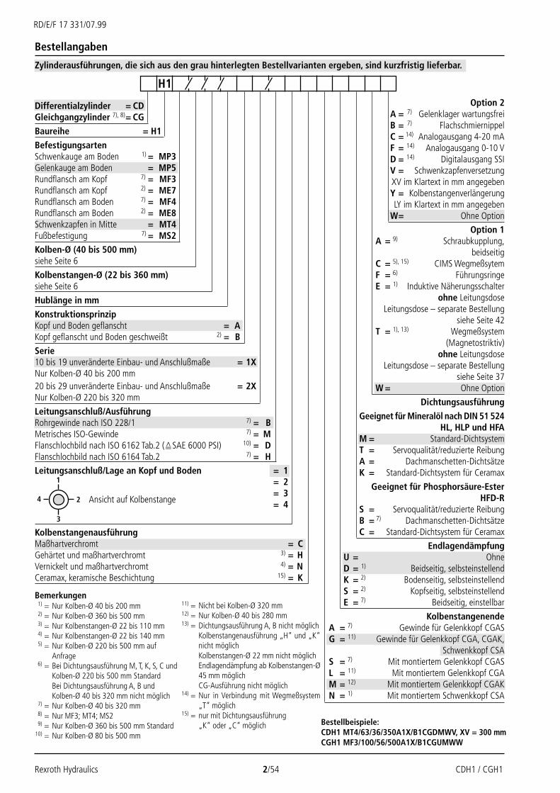
Bestellangaben
Differentialzylinder = CDGleichgangzylinder 7), 8)= CG
Baureihe = H1
BefestigungsartenSchwenkauge am Boden 1) = MP3Gelenkauge am Boden = MP5Rundflansch am Kopf 7) = MF3Rundflansch am Kopf 2) = ME7Rundflansch am Boden 7) = MF4Rundflansch am Boden 2) = ME8Schwenkzapfen in Mitte = MT4Fußbefestigung 7) = MS2Kolben-Ø (40 bis 500 mm)siehe Seite 6
Kolbenstangen-Ø (22 bis 360 mm)siehe Seite 6
Hublänge in mm
KonstruktionsprinzipKopf und Boden geflanscht = AKopf geflanscht und Boden geschweißt 2) = BSerie10 bis 19 unveränderte Einbau- und Anschlußmaße = 1XNur Kolben-Ø 40 bis 200 mm20 bis 29 unveränderte Einbau- und Anschlußmaße = 2XNur Kolben-Ø 220 bis 320 mm
Leitungsanschluß/AusführungRohrgewinde nach ISO 228/1 7) = BMetrisches ISO-Gewinde 7) = MFlanschlochbild nach ISO 6162 Tab.2 (SAE 6000 PSI) 10) = DFlanschlochbild nach ISO 6164 Tab.2 7) = HLeitungsanschluß/Lage an Kopf und Boden = 1
= 2= 3= 4
KolbenstangenausführungMaßhartverchromt = CGehärtet und maßhartverchromt 3) = HVernickelt und maßhartverchromt 4) = NCeramax, keramische Beschichtung 15) = K
Option 2A = 7) Gelenklager wartungsfreiB = 7) FlachschmiernippelC = 14) Analogausgang 4-20 mAF = 14) Analogausgang 0-10 VD = 14) Digitalausgang SSIV = SchwenkzapfenversetzungXV im Klartext in mm angegebenY = Kolbenstangenverlängerung LY im Klartext in mm angegebenW= Ohne Option
Option 1A = 9) Schraubkupplung,
beidseitigC = 5), 15) CIMS WegmeßsytemF = 6) FührungsringeE = 1) Induktive Näherungsschalter
ohne LeitungsdoseLeitungsdose – separate Bestellung
siehe Seite 42T = 1), 13) Wegmeßsystem
(Magnetostriktiv)ohne Leitungsdose
Leitungsdose – separate Bestellungsiehe Seite 37
W = Ohne Option
Dichtungsausführung
Geeignet für Mineralöl nach DIN 51 524HL, HLP und HFA
M = Standard-DichtsystemT = Servoqualität/reduzierte ReibungA = Dachmanschetten-DichtsätzeK = Standard-Dichtsystem für Ceramax
Geeignet für Phosphorsäure-EsterHFD-R
S = Servoqualität/reduzierte ReibungB = 7) Dachmanschetten-DichtsätzeC = Standard-Dichtsystem für Ceramax
EndlagendämpfungU = OhneD = 1) Beidseitig, selbsteinstellendK = 2) Bodenseitig, selbsteinstellendS = 2) Kopfseitig, selbsteinstellendE = 7) Beidseitig, einstellbar
KolbenstangenendeA = 7) Gewinde für Gelenkkopf CGASG = 11) Gewinde für Gelenkkopf CGA, CGAK,
Schwenkkopf CSAS = 7) Mit montiertem Gelenkkopf CGASL = 11) Mit montiertem Gelenkkopf CGAM = 12) Mit montiertem Gelenkkopf CGAKN = 1) Mit montiertem Schwenkkopf CSA
H1
Bestellbeispiele:CDH1 MT4/63/36/350A1X/B1CGDMWV, XV = 300 mmCGH1 MF3/100/56/500A1X/B1CGUMWW
Bemerkungen1) = Nur Kolben-Ø 40 bis 200 mm2) = Nur Kolben-Ø 360 bis 500 mm3) = Nur Kolbenstangen-Ø 22 bis 110 mm4) = Nur Kolbenstangen-Ø 22 bis 140 mm5) = Nur Kolben-Ø 220 bis 500 mm auf
Anfrage6) = Bei Dichtungsausführung M, T, K, S, C und
Kolben-Ø 220 bis 500 mm StandardBei Dichtungsausführung A, B undKolben-Ø 40 bis 320 mm nicht möglich
7) = Nur Kolben-Ø 40 bis 320 mm8) = Nur MF3; MT4; MS29) = Nur Kolben-Ø 360 bis 500 mm Standard
10) = Nur Kolben-Ø 80 bis 500 mm
Ansicht auf Kolbenstange
11) = Nicht bei Kolben-Ø 320 mm12) = Nur Kolben-Ø 40 bis 280 mm13) = Dichtungsausführung A, B nicht möglich
Kolbenstangenausführung „H“ und „K“nicht möglichKolbenstangen-Ø 22 mm nicht möglichEndlagendämpfung ab Kolbenstangen-Ø45 mm möglichCG-Ausführung nicht möglich
14) = Nur in Verbindung mit Wegmeßsystem„T“ möglich
15) = nur mit Dichtungsausführung„K“ oder „C“ möglich
Zylinderausführungen, die sich aus den grau hinterlegten Bestellvarianten ergeben, sind kurzfristig lieferbar.

CDH1 / CGH1 3/54 Rexroth Hydraulics
RD/E/F 17 331/07.99
1
2
3
4 View on piston rod
Ordering details
Differential cylinder = CDDouble rod cylinder 7), 8) = CG
Series = H1
Mounting typesPlain clevis at base 1) = MP3Self-aligning clevis at base = MP5Round flange at head 7) = MF3Round flange at head 2) = ME7Round flange at base 7) = MF4Round flange at base 2) = ME8Plain clevis at centre = MT4Foot mounting 7) = MS2Piston Ø (40 to 500 mm)See page 6
Piston rod Ø (22 to 360 mm)See page 6
Stroke length in mm
Design principleHead and rear flanged = AHead flanged and rear welded 2) = BSeries10 to 19 unchanged installation and connection dimensions = 1XOnly piston Ø 40 to 200 mm20 to 29 unchanged installation and connection dimensions = 2XOnly piston Ø 220 to 320 mm
Connection ports/versionPipe thread to ISO 228/1 7) = BMetric ISO thread 7) = MFlange hole pattern to ISO 6162 Tab.2 (SAE 6000 PSI) 10) = DFlange hole pattern to ISO 6164 Tab.2 7) = HConnection port/position at head and rear = 1
= 2= 3= 4
Piston rod versionHard chromium plated = CHardened and hard chromium plated 3) = HNickel plated and hard chromium plated 4) = NCeramax, ceramic coating 15) = K
Option 2A = 7) Maintenance free plain bearingB = 7) Flanged grease nippleC = 14) Analogue output 4-20 mAF = 14) Analogue output 0-10 VD = 14) Digital output SSIV = Enter trunnion displacement
XV in clear text in mmY = Enter piston rod extension
LY in clear text in mmW = Without option
Option 1A = 9) Coupling, on both sidesC = 5), 15) CIMS position measuring
systemF = 6) Guide ringsE = 1) Inductive proximity switch
Without plug-in connectorPlug-in connector – separate order
see page 42T = 1), 13) Pos. measuring system
(magnetostrictive)Without plug-in connector
Plug-in connector – separate ordersee page 37
W = Without option
Seal version
Suitable for mineral oil to DIN 51 524HL, HLP and HFA
M = Standard seal systemT = Servo quality/reduced frictionA = Chevron seal kitsK = Standard seal system for Ceramax
Suitable for phosphate esterHFD-R
S = Servo quality/reduced frictionB = 7) Chevron seal kitsC = Standard seal system for Ceramax
End position cushioningU = WithoutD = 1) Both ends, self-regulatingK = 2) Rear end, self-regulatingS = 2) Head end, self-regulatingE = 7) Both ends, adjustable
Piston rod endA = 7) Thread for self-aligning clevis CGASG = 11) Thread for self-aligning clevis CGA, CGAK,
plain clevis CSAS = 7) With mounted self-aligning clevis CGASL = 11) With mounted self-aligning clevis CGAM = 12) With mounted self-aligning clevis CGAKN = 1) With mounted plain clevis CSA
H1
Ordering example:CDH1 MT4/63/36/350A1X/B1CGDMWV, XV = 300 mmCGH1 MF3/100/56/500A1X/B1CGUMWW
Notes1) = Only piston Ø 40 to 200 mm2) = Only piston Ø 360 to 500 mm3) = Only piston rod Ø 22 to 110 mm4) = Only piston rod Ø 22 to 140 mm5) = Only piston Ø 220 to 500 mm on
request6) = Standard for seal versions M, T, K, S, C
and piston Ø 220 bis 500 mmNot possible for seal versions A, Band Ø 40 to 320 mm
7) = Only piston Ø 40 to 320 mm8) = Only MF3; MT4; MS29) = Only piston Ø 360 to 500 mm
standard
10) = Only piston Ø 80 to 500 mm11) = Not for piston Ø 320 mm12) = Only piston Ø 40 to 280 mm13) = Seal versions A, B not possible
Piston rod version „H“ and „K“not possiblePiston rod Ø 22 mm not possibleEnd position damping possible frompiston rod Ø 45 mmCG version not possible
14) = Only possible in conjunction withposition measuring system „T“
15) = Only possible with seal versions„K“ or „C“
Cylinder types which are marked in grey are readily available.

Rexroth Hydraulics 4/54 CDH1 / CGH1
RD/E/F 17 331/07.99
1
2
3
4
Codification
Vérin différentiel = CDVérin double tige 7), 8) = CGSérie = H1
Types de fixationTenon arrière fixe 1) = MP3Tenon arrière à rotule = MP5Bride circulaire avant 7) = MF3Bride circulaire avant 2) = ME7Bride circulaire arrière 7) = MF4Bride circulaire arrière 2) = ME8Tourillon central = MT4Pattes latérales 7) = MS2
Ø de piston (40 à 500 mm)voir page 6
Ø de tige (22 à 360 mm)voir page 6
Course en mm
Principe de constructionAvec bride avant et arrière = ATête bridée et fond soudé 2) = B
Série10 à 19 cotes de montage et de raccordement identiques = 1Xuniquement Ø de piston 40 à 200 mm20 à 29 cotes de montage et de raccordement identiques = 2Xuniquement Ø de piston 220 à 320 mm
Exécution des orifices d‘alimentationTaraudage gaz selon ISO 228/1 7)= BTaraudage métrique ISO 7) = MRaccordement par bride ISO 6162 Tab.2 (SAE 6000 PSI) 10) = DRaccordement par bride ISO 6164 Tab.2 7) = H
Position des orifice d‘alimentation sur tête et fond de vérin = 1= 2= 3= 4
Exécution de la tigechromée dur = Ctrempée et chromée dur 3) = Hnickelée et chromée dur 4) = NCeramax, revêtement céramique 15) = K
Option N° 2A = 7) rotule sans entretienB = 7) graisseur à tête plateC = 14) sortie analogique 4-20 mAF = 14) sortie analogique 0-10 VD = 14) sortie numérique SSIV = cote XV du tourillon à
indiquer en mm dans le textede la commande
Y = prolongation LY de la tige àindiquer en mm dans le texte
de la commandeW= sans option
Option N° 1A = 9) Accouplement fileté, des deux côtésC = 5), 15) Systéme de mesure de
position CIMSF = 6) bagues de guidageE = 1) détecteur inductif de proximité
sans connecteur femelleconnecteur femelle à commander
séparément, voir page 42T = 1), 13) système de mesure de
position (magnétostrictif)sans connecteur femelle
connecteur femelle à commanderséparément, voir page 37
W = sans option
Exécution des joints
pour huile minérale selon DIN 51 524HL, HLP et HFA
M = joints standardT = qualité servo/faible frottementA = pochettes de joints à chevronsK = joints standard pour Ceramax
pour ester phosphateHFD-R
S = qualité servo/faible frottementB = 7) pochettes de joints à chevronsC = joints standard pour Ceramax
Amortissement de fin de courseU = sans amortissement de fin de courseD = 1) aux 2 extrémités, auto-régulateurK = 2) côté fond, auto-régulateurS = 2) côté tête, auto-régulateurE = 7) aux 2 extrémités, réglable
Extrémité de tigeA = 7) filetage pour tenon à rotule CGASG = 11) filetage pour tenon à rotule CGA, CGAK,
et pour tenon à bague CSAS = 7) avec tenon à rotule CGAS montéL = 11) avec tenon à rotule CGA montéM = 12) avec tenon à rotule CGAK montéN = 1) avec tenon à bague CSA monté
H1
Exemples de commande :CDH1 MT4/63/36/350A1X/B1CGDMWV, XV = 300 mmCGH1 MF3/100/56/500A1X/B1CGUMWW
tige face à soi
Remarques1) = uniquement Ø de piston 40 à 200 mm2) = uniquement Ø de piston 360 à 500 mm3) = uniquement Ø de tige 22 à 110 mm4) = uniquement Ø de tige 22 à 140 mm5) = uniquement Ø de piston 220 à
500 mm, sur demande6) = standard avec joints M, T, K, S, C et
Ø de piston 220 à 500 mmnon réalisable avec joints A, B etØ 40 à 320 mm
7) = uniquement Ø de piston 40 à 320 mm8) = uniquement MF3; MT4; MS29) = uniquement Ø de piston 360 à
500 mm, standard
10) = uniquement Ø de piston 80 à 500 mm11) = non réalisable avec Ø de piston 320 mm12) = uniquement Ø de piston 40 à 280 mm13) = joints de types A, B non réalisables
tige „H“ et „K“ non réalisableØ de tige 22 mm non réalisableamortissement de fin de courseréalisable à partir du Ø de tige 45 mmexécution CG non réalisable
14) = réalisable uniquement avec système demesure de position „T“
15) = réalisable uniquement avecjoints de type „K“ ou „C“
les exécutions constituées à partir des indices de commande sur fond gris sont livrables rapidement.

CDH1 / CGH1 5/54 Rexroth Hydraulics
RD/E/F 17 331/07.99
Technische Daten / Technical data / Données techniques
Normen:
Mannesmann Rexroth Standard; Hauptab-maße wie Kolben-Ø und Kolbenstangen-Øentsprechend DIN ISO 3320.
Nenndruck: 250 barStatischer Prüfdruck: 375 barHöhere Betriebsdrücke auf Anfrage.
Die angegebenen Betriebsdrücke gelten fürAnwendungen bei stoßfreiem Betrieb. Beiextremen Belastungen, wie z. B. hoher Zyklen-folge, müssen Befestigungselemente undKolbenstangengewindeverbindungen fürDauerfestigkeit ausgelegt werden.
Einbaulage: Beliebig
Druckflüssigkeit:
Mineralöle DIN 51 524 (HL, HLP)
Phosphorsäure-Ester (HFD-R;bei Dichtungsausführung "C"-20 °C bis +50 °C)
HFA (+5 °C bis +55 °C)
Wasserglykol HFC auf Anfrage
Druckflüssigkeit-Temperaturbereich:-20 °C bis +80 °C
Viskositätsbereich:2,8 bis 380 mm2/s
Verschmutzungsgrad:max. zulässiger Verschmutzungsgrad derDruckflüssigkeit nach NAS 1638 Klasse 10.
Als Filterelement wird ein Filter mit einerMindestrückhalterate von β10 >75empfohlen.
Hubgeschwindigkeit: 0,5 m/s(abhängig vom Leitungsanschluß)
Entlüftung serienmäßig:gegen Herausdrehen gesichert
Abnahme: Jeder Zylinder wird nachMannesmann Rexroth-Standard geprüft.
Zylinder, deren Einsatzdaten von denKenngrößen abweichen, sind auf Wunschlieferbar.
Standards:
Mannesmann Rexroth standard; maindimensions such as piston Ø and piston rodØ meet DIN ISO 3320 requirements.
Nominal pressure: 250 barStatic proof pressure: 375 barHigher operating pressures on enquiry.
The specified operating pressures are onlyvalid for applications with shock-freeoperation. If extreme loads occur, e.g. ashappens in high sequence cycles, the fixingsand piston rod thread connections need tobe designed for durability (fatigue strength).
Installation position: Arbitrary
Hydraulic fluid:Mineral oils DIN 51 524 (HL, HLP)
Phosphate ester (HFD-R;for seal version "C"-20 °C to +50 °C)
HFA (+5 °C to +55 °C)
Water glycol HFC on enquiry
Fluid temperature range:-20 °C to +80 °C
Viscosity range:2.8 to 380 mm2/s
Cleanliness:Max. permissible degree of contaminationof the hydraulic fluid to NAS 1638 class 10.
We therefore recommend as filtrationelement a filter with a minimum retentionrate of β10 >75.
Stroke velocity: 0.5 m/s(depending on the connection ports)
Bleed screw as standard:Secured against unscrewing
Acceptance: Each cylinder is tested toMannesmann Rexroth standards.
Cylinders outside the above parameters arealso available, if required.
Normes:
norme Mannesmann Rexroth; les cotesprincipales comme Ø de piston et Ø de tigesont conformes aux normes DIN ISO 3320.
Pression nominale: 250 barPression d'essai statique: 375 barPressions de service supérieures surdemande.
Les pressions nominales indiquéess'appliquent à un fonctionnement sansà-coups. En cas de charges extrêmes, tellesque celles dues à des fréquences defonctionnement élevées, les éléments defixation et les filetages de liaison des tigesdoivent être conçus pour résister à la fatigue.
Position de montage: au choix
Fluide de pression:Huile minérale selon DIN 51 524 (HL, HLP)
ester phosphate (HFD-R;pour version de joints "C"-20 °C à +50 °C)
HFA (+5 °C à +55 °C)
eau/glycol HFC sur demande
Plage de température du fluide:-20 °C à +80 °C
Plage de viscosité:2,8 à 380 mm2/s
Degré de pollution:Degré de pollution maxi admissible dufluide selon NAS 1638: classe 10.
Nous recommandons pour cela d'utiliser unfiltre dont le taux de rétention mini est deβ10 >75.
Vitesse maxi de la tige: 0.5 m/s(selon l'orifice de raccordement)
Purge de série:Protégée contre desserrage
Contrôle: Chaque vérin est essayé selonles normes de Mannesmann Rexroth.
Des vérins avec des caractéristiques autresque les données techniques ci-dessus sontlivrables sur demande.
Rexroth Hydraulics 6/54 CDH1 / CGH1
RD/E/F 17 331/07.99
F1
F3 qV3
A3 A1
qV1
F2 A2
qV2
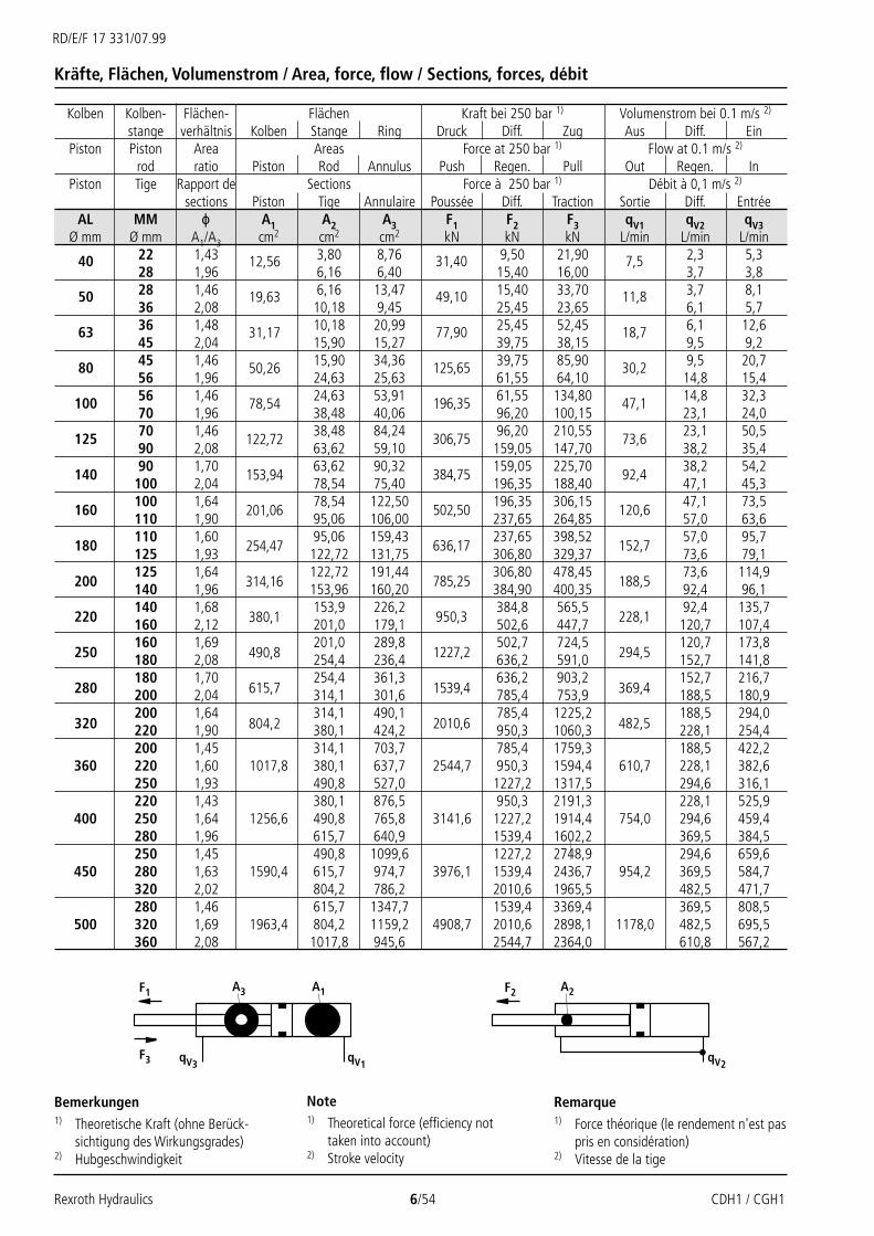
Kräfte, Flächen, Volumenstrom / Area, force, flow / Sections, forces, débit
Kolben Kolben- Flächen- Flächen Kraft bei 250 bar 1) Volumenstrom bei 0.1 m/s 2)
stange verhältnis Kolben Stange Ring Druck Diff. Zug Aus Diff. EinPiston Piston Area Areas Force at 250 bar 1) Flow at 0.1 m/s 2)
rod ratio Piston Rod Annulus Push Regen. Pull Out Regen. InPiston Tige Rapport de Sections Force à 250 bar 1) Débit à 0,1 m/s 2)
sections Piston Tige Annulaire Poussée Diff. Traction Sortie Diff. EntréeAL MM ϕ A1 A2 A3 F1 F2 F3 qV1 qV2 qV3
Ø mm Ø mm A1/A3 cm2 cm2 cm2 kN kN kN L/min L/min L/min22 1,43 3,80 8,76 9,50 21,90 2,3 5,328 1,96 6,16 6,40 15,40 16,00 3,7 3,828 1,46 6,16 13,47 15,40 33,70 3,7 8,136 2,08 10,18 9,45 25,45 23,65 6,1 5,736 1,48 10,18 20,99 25,45 52,45 6,1 12,645 2,04 15,90 15,27 39,75 38,15 9,5 9,245 1,46 15,90 34,36 39,75 85,90 9,5 20,756 1,96 24,63 25,63 61,55 64,10 14,8 15,456 1,46 24,63 53,91 61,55 134,80 14,8 32,370 1,96 38,48 40,06 96,20 100,15 23,1 24,070 1,46 38,48 84,24 96,20 210,55 23,1 50,590 2,08 63,62 59,10 159,05 147,70 38,2 35,490 1,70 63,62 90,32 159,05 225,70 38,2 54,2
100 2,04 78,54 75,40 196,35 188,40 47,1 45,3100 1,64 78,54 122,50 196,35 306,15 47,1 73,5110 1,90 95,06 106,00 237,65 264,85 57,0 63,6110 1,60 95,06 159,43 237,65 398,52 57,0 95,7125 1,93 122,72 131,75 306,80 329,37 73,6 79,1125 1,64 122,72 191,44 306,80 478,45 73,6 114,9140 1,96 153,96 160,20 384,90 400,35 92,4 96,1140 1,68 153,9 226,2 384,8 565,5 92,4 135,7160 2,12 201,0 179,1 502,6 447,7 120,7 107,4160 1,69 201,0 289,8 502,7 724,5 120,7 173,8180 2,08 254,4 236,4 636,2 591,0 152,7 141,8180 1,70 254,4 361,3 636,2 903,2 152,7 216,7200 2,04 314,1 301,6 785,4 753,9 188,5 180,9200 1,64 314,1 490,1 785,4 1225,2 188,5 294,0220 1,90 380,1 424,2 950,3 1060,3 228,1 254,4200 1,45 314,1 703,7 785,4 1759,3 188,5 422,2
360 220 1,60 1017,8 380,1 637,7 2544,7 950,3 1594,4 610,7 228,1 382,6250 1,93 490,8 527,0 1227,2 1317,5 294,6 316,1220 1,43 380,1 876,5 950,3 2191,3 228,1 525,9
400 250 1,64 1256,6 490,8 765,8 3141,6 1227,2 1914,4 754,0 294,6 459,4280 1,96 615,7 640,9 1539,4 1602,2 369,5 384,5250 1,45 490,8 1099,6 1227,2 2748,9 294,6 659,6
450 280 1,63 1590,4 615,7 974,7 3976,1 1539,4 2436,7 954,2 369,5 584,7320 2,02 804,2 786,2 2010,6 1965,5 482,5 471,7280 1,46 615,7 1347,7 1539,4 3369,4 369,5 808,5
500 320 1,69 1963,4 804,2 1159,2 4908,7 2010,6 2898,1 1178,0 482,5 695,5360 2,08 1017,8 945,6 2544,7 2364,0 610,8 567,2
Bemerkungen1) Theoretische Kraft (ohne Berück-
sichtigung des Wirkungsgrades)2) Hubgeschwindigkeit
Note1) Theoretical force (efficiency not
taken into account)2) Stroke velocity
Remarque1) Force théorique (le rendement n'est pas
pris en considération)2) Vitesse de la tige
12,56
19,63
31,17
50,26
78,54
122,72
153,94
201,06
254,47
314,16
380,1
490,8
615,7
804,2
40
50
63
80
100
125
140
160
180
200
220
250
280
320
31,40
49,10
77,90
125,65
196,35
306,75
384,75
502,50
636,17
785,25
950,3
1227,2
1539,4
2010,6
7,5
11,8
18,7
30,2
47,1
73,6
92,4
120,6
152,7
188,5
228,1
294,5
369,4
482,5

CDH1 / CGH1 7/54 Rexroth Hydraulics
RD/E/F 17 331/07.99
Masse Zylinder /Cylinder weight / Masse du vérin
Toleranzen nach ISO 8135 / Tolerances to ISO 8135 / Tolérances selon ISO 8135EinbaumaßeInstallation dimensions WC WF XC1) XO1) XS2) XV1) ZJ1) ZP1)
Encombrement
BefestigungsartMounting type MF3 ME7 MP3 MP5 MS21) MT4 ME8 MF4Type de fixationHublänge / Stroke / Course Toleranzen / tolerances / tolérances
0 - 499 ± 2 ± 1,5 ± 1,5 ± 1,5 ± 2 ± 2 ± 1,5 ± 1,5 + 350 - 1249 ± 2,8 ± 2,8 ± 2 ± 2 ± 2,8 ± 2,8 ± 2 ± 2 + 4
1250 - 3149 ± 4 ± 4 ± 3 ± 3 ± 4 ± 4 ± 3 ± 3 + 63150 - 8000 ± 8 ± 8 ± 5 ± 5 ± 8 ± 8 ± 5 ± 5 + 10
Hubtoleranzen
Stroke tolerances
Tolérancesde course
1) Inklusive Hublänge / Stroke length included / Course inclue
Kolben Kolben- CD-Zylinder pro 100 mm CG-Zylinder pro 100 mmstange bei 0 mm Hublänge Hublänge bei 0 mm Hublänge Hublänge
Piston Piston CD cylinder per 100 mm CG cylinder per 100 mmrod at 0 mm stroke stroke at 0 mm stroke stroke
Piston Tige Vérin CD par 100 mm Vérin CG par 100 mmà 0 mm de course de course à 0 mm de course de course
AL MM MP3; MP5 MF3; MF4 MT4 MS2 MF3 MT4 MS2ME7; ME8
Ø Ø kg kg kg kg kg kg kg kg kg22 7 9 9 9 0,9 10 9 9 1,228 7 9 9 9 1,0 10 9 10 1,528 10 14 12 12 1,2 15 14 14 1,636 10 14 12 13 1,5 15 14 14 2,336 16 22 19 19 2,1 24 21 21 2,945 16 22 19 20 2,6 24 22 22 3,845 25 30 29 31 2,9 34 33 35 4,156 26 31 30 32 3,6 35 34 36 5,556 43 52 50 52 4,6 59 56 58 6,670 44 53 51 53 5,7 60 58 60 8,870 79 93 91 90 7,3 103 101 100 10,390 80 95 93 92 9,2 106 105 104 14,290 111 127 130 131 10,7 145 147 148 15,7
100 112 128 131 132 11,9 146 149 150 18,1100 168 198 200 209 12,6 230 233 241 18,8110 169 200 202 210 13,9 234 236 244 21,4110 236 270 269 278 14,7 314 312 322 22,1125 239 272 271 281 16,8 319 318 327 26,5125 306 348 346 358 19,0 369 367 380 28,6140 309 351 349 361 21,5 376 373 386 33,5140 27,1 39,1160 30,9 46,7160 32,7 48,5180 36,9 56,9180 44,2 64,2200 48,8 73,4200 55,2 79,8220 60,4 90,2200 53,0
360 220 1056 1032 1177 – 58,2 – – – –250 66,9220 67,4
400 250 1456 1381 1586 – 76,1 – – – –280 85,9250 81,1
450 280 1852 1748 2014 – 90,9 – – – –320 105,7280 123,6
500 320 2457 2272 2718 – 138,4 – – – –360 155,1
2) Nicht genormt / Not standardized / Non normalisé
452 515 479 509
582 664 618 649
753 846 784 822
1125 1290 1180 1222
598 562 593
784 739 770
981 919 957
1452 1343 1385
40
50
63
80
100
125
140
160
180
200
220
250
280
320

Rexroth Hydraulics 8/54 CDH1 / CGH1
RD/E/F 17 331/07.99
Befestigungsübersicht / Mounting type overview / Vue d‘ensemble des fixations
CDH1 MP5siehe Seite / see pages / voir pages 14, 15
CDH1 MF3/ME7siehe Seite / see pages / voir pages 16, 17
CGH1 MF3siehe Seite / see pages / voir pages 16, 17
CDH1 MP3siehe Seite / see pages / voir pages 12,13
CDH1 MF4/ME8siehe Seite / see pages / voir pages 18, 19

CDH1 / CGH1 9/54 Rexroth Hydraulics
RD/E/F 17 331/07.99
Befestigungsübersicht / Mounting type overview / Vue d‘ensemble des fixations
CDH1 MT4siehe Seite / see pages / voir pages 20, 21
CGH1 MT4siehe Seite / see pages / voir pages 20, 21
CDH1 MS2siehe Seite / see pages / voir pages 22, 23
CGH1 MS2siehe Seite / see pages / voir pages 22, 23

Rexroth Hydraulics 10/54 CDH1 / CGH1
RD/E/F 17 331/07.99
"A"
"A"
7)
EE
Ø D
A
KK
Ø M
M
Ø D
WA
A ZB + X*
PJ + X*Y
Ø D4
EE
Ø D4
X1
NV
X2 G 1
/41)
"A"
"A"
Ø DKK
PJ +X*
Ø M
M
ZB +X*
EE4)
Y
X1
WA
A
Ø D
A
EE4)
3)3)
X2
Bemerkungen
Die auf dieser Seite angegebenen Maßesind allgemein gültige Maße für dieseBaureihe.
Notes
The dimensions indicated on this page aregenerally valid for this series.
Remarques
Les dimensions indiquées sur cette pagesont les dimensions valables en généralpour cette série.
Grundausführung H1 / Basic version H1 / Version de base H1
CDH1; AL-Ø 360-500 mm
CDH1; AL-Ø 40-320 mm

CDH1 / CGH1 11/54 Rexroth Hydraulics
RD/E/F 17 331/07.99
Maße H1 (in mm) / Dimensions H1 (in mm) / Encombrement H1 (en mm)
AL MM KK A KK A NV D DA D4 EE EE PJ WA X1 X2 Y ZBØ Ø 5) 5) 6) 6) 2) 4) 4)
40 M16x1,5 16 M18x2 30 88 50 34 G1/2 M22x1,5 120 14 41 41 79 226
50 M22x1,5 22 M24x2 35 102 60 34 G1/2 M22x1,5 120 18 48,5 48,5 87 233
63 M28x1,5 28 M30x2 45 120 78 42 G3/4 M27x2 133 22 56,5 56,5 100 262
80 M35x1,5 35 M39x3 55 140 95 42 G3/4 M27x2 146 20 67 67 104 280
100 M45x1,5 45 M50x3 75 170 125 47 G1 M33x2 171 30 82 82 124 330
125 M58x1,5 58 M64x3 95 206 150 58 G1 1/4 M42x2 205 32 99 99 135 382
140 M65x1,5 65 M80x3 110 226 170 58 G1 1/4 M42x2 219 35 109,5 109,5 156 420
160 M80x2 80 M90x3 120 265 190 65 G1 1/2 M48x2 240 40 129 129 185 475
180 M100x2 100 M100x3 140 292 210 65 G1 1/2 M48x2 264 40 142,5 142,5 199 515
200 M110x2 110 M110x4 150 310 235 65 G1 1/2 M48x2 278 40 152 152 205 535
220 M120x3 120 M120x4 160 355 273 65 G1 1/2 M48x2 326 40 174 174 242 635
250 M120x3 120 M120x4 160 395 305 65 G1 1/2 M48x2 326 40 194 194 266 659
280 M130x3 130 M150x4 190 425 343 65 G1 1/2 M48x2 375 40 210 210 282 744
320 – – M160x4 200 490 394 65 G1 1/2 M48x2 431 40 242 242 287 815
200360 220 M150x3 147 – – – 456 419 – NW 51 4) 418 40 200 217 280 765
250220
400 250 M160x4 169 – – – 520 470 – NW 51 4) 418 40 221 251 340 825280250
450 280 M180x4 186 – – – 570 521 – NW 51 4) 448 40 256 276 340 855320280
500 320 M200x4 201 – – – 644 610 – NW 51 4) 448 40 290 314 345 860360
22282836364545565670709090
100100110110125125140140160160180180200200220
1622223030363646466060757585859595110110120120140140160160180180200
BemerkungenAL = Kolben-ØMM = Kolbenstangen-ØX* = Hublänge
Hub- und Gesamtlängentoleranzennach ISO 8135
1) = Entlüftung: Bei Sicht auf die Kolben-stange ist die Lage immer 90° zumLeitungsanschluß versetzt (imUhrzeigersinn)
2) = Ø D4 max. 0,5 mm tief3) = Schraubkupplung/Entlüftung4) = Flanschanschlüsse siehe seperate
Tabelle Seite 34 und 355) = Gewindeausführung "G"6) = Gewindeausführung "A"7) = Drosselventil nur bei Endlagen-
dämpfung "E" (180° zur Entlüftung)
NotesAL = Piston ØMM = Piston rod ØX* = Stroke length
Stroke and overall length tolerances toISO 8135
1) = Bleed point: Viewed to the piston rod,this point is always offset by 90°(clockwise) with reference to theconnection ports
2) = Ø D4 max. 0.5 mm deep3) = Coupling/bleed point4) = Flange connection see seperate table
page 34 and 355) = Thread version "G"6) = Thread version "A"7) = Throttle valve only with end position
cushioning "E" (180° with regard tobleeding point)
RemarquesAL = Ø de pistonMM = Ø de tigeX* = Course
Tolérances de course et des longueurstotales selon ISO 8135
1) = Purges: tige face à soi, la purge setrouve toujours à 90° à droite parrapport à l'orifice d'alimentation
2) = Ø D4 profondeur maxi 0,5 mm3) = Raccord minimess/purges4) = Accouplement fileté : voir tableau
séparé pages 34 et 355) = Filetage version "G"6) = Filetage version "A"7) = Valve de réglage (étrangleur) pour
amortissement de fin de course "E"(orientée de 180° par rapport à lapurge d'air)

Rexroth Hydraulics 12/54 CDH1 / CGH1
RD/E/F 17 331/07.99
Ø C
D
EW
MR
1)
LM1XC + X*
"A"
"A-A"
"A"
Befestigungsart MP3 / Mounting MP3 / Fixation MP3
CDH1 MP3; AL-Ø 40-200 mm

CDH1 / CGH1 13/54 Rexroth Hydraulics
RD/E/F 17 331/07.99
Maße MP3 (in mm) / Dimensions MP3 (in mm) / Encombrement MP3 (en mm)
AL MM CD CB EW L MR M1 UB XC
Ø Ø ± 1 - 0,4 ± 5
40 25H11 – 23 32,5 31 28 – 252
50 30H11 – 28 37,5 36 32,5 – 265
63 35H11 – 30 45 42 40 – 302
80 40H11 – 35 50 52 50 – 330
100 50H11 – 40 60 65 62,5 – 385
125 60H11 – 50 70 70 70 – 447
140 70H11 – 55 75 82 82 – 490
160 80H11 – 60 85 95 95 – 550
180 90H11 – 65 90 113 113 – 610
200 100H11 – 70 115 125 125 – 645
Bemerkungen
Hauptmaße auf Seite 10 und 11
AL = Kolben-Ø
MM = Kolbenstangen-Ø
X* = Hublänge1) = Schmiernippel Kegelkopf
Form A nach DIN 71 412
Notes
For main dimensions, see pages 10 and 11
AL = Piston Ø
MM = Piston rod Ø
X* = Stroke length1) = Cone head grease nipple
form A to DIN 71 412
Remarques
Cotes principales, voir pages 10 et 11
AL = Ø du piston
MM = Ø de la tige
X* = Course1) = Graisseur à tête sphérique
forme A selon DIN 71 412
22
28
28
36
36
45
45
56
56
70
70
90
90
100
100
110
110
125
125
140

Rexroth Hydraulics 14/54 CDH1 / CGH1
RD/E/F 17 331/07.99
XO + X*
LT
M1
MS
1), 3)
EX
EP
Ø C
X2)
ZZ
"A"
"A-A"
"A"
XO + X* EP
EXLT
M1
MS
3)
ZZ
"A"
"A-A"
"A"Ø
CX2
)
Befestigungsart MP5 / Mounting MP5 / Fixation MP5
CDH1 MP5; AL-Ø 40-320 mm
CDH1 MP5; AL-Ø 360-500 mm

CDH1 / CGH1 15/54 Rexroth Hydraulics
RD/E/F 17 331/07.99
Maße MP5 (in mm) / Dimensions MP5 (in mm) / Encombrement MP5 (en mm)
AL MM CX EP EX LT MS M1 XO Z
Ø Ø
40 25-0,010 23-0,4 20-0,12 32,5 31 28 252 7°
50 30-0,010 28-0,4 22-0,12 37,5 36 32,5 265 6°
63 35-0,012 30-0,4 25-0,12 45 42 40 302 6°
80 40-0,012 35-0,4 28-0,12 50 52 50 330 7°
100 50-0,012 40-0,4 35-0,12 60 65 62,5 385 6°
125 60-0,015 50-0,4 44-0,15 70 70 70 447 6°
140 70-0,015 55-0,4 49-0,15 75 82 82 490 6°
160 80-0,015 60-0,4 55-0,15 85 95 95 550 6°
180 90-0,020 65-0,4 60-0,20 90 113 113 610 5°
200 100-0,020 70-0,4 70-0,20 115 125 125 645 7°
220 110-0,020 80-0,4 70-0,20 125 132,5 142,5 750 6°
250 110-0,020 80-0,4 70-0,20 140 150 160 789 6°
280 120-0,020 90-0,4 85-0,20 150 170 180 884 6°
320 140-0,020 110-0,4 90-0,25 175 190 200 980 7°
200360 220 160-0,025 120±2 105-0,25 253 200 240 1040 4°
250220
400 250 180-0,025 130±2 105-0,25 291 225 285 1140 4°280250
450 280 200-0,030 150±2 130-0,30 314 250 310 1195 4°320280
500 320 220-0,030 160±2 135-0,30 333 280 350 1220 4°360
BemerkungenHauptmaße auf Seite 10 und 11AL = Kolben-ØMM = Kolbenstangen-ØX* = Hublänge1) = Schmiernippel Kegelkopf
Form A nach DIN 71 4122) = zugehöriger Bolzen-Ø m6;
zugehöriger Bolzen-Ø j6 beiwartungsfreiem Gelenklager
3) = FlachschmiernippelDIN 3404-ABei Kolben-Ø 360 bis 500 mmStandard
NotesFor main dimensions, see pages 10 and 11AL = Piston ØMM = Piston rod ØX* = Stroke length1) = Cone head grease nipple
form A to DIN 71 4122) = Associated pin Ø m6;
associated pin Ø j6 withmaintenance free self-aligning clevis
3) = Flanged grease nippleDIN 3404-AFor piston Ø 360 to 500 mmas standard
RemarquesCotes principales, voir pages 10 et 11AL = Ø du pistonMM = Ø de la tigeX* = Course1) = Graisseur à tête sphérique
forme A selon DIN 71 4122) = Tolérance sur le Ø de l'axe: m6
Tolérance sur le Ø de l‘axe : j6 avecrotule sans entretien
3) = Graisseur à tête plateDIN 3404-AStandard pour Ø de piston360 à 500 mm
22282836364545565670709090
100100110110125125140140160160180180200200220

Rexroth Hydraulics 16/54 CDH1 / CGH1
RD/E/F 17 331/07.99
"A"
"A"
FC
UC
FB
Ø R
D
ZB + X*
VDVD
WC NF
α
1)
"A"
"A"
FB
FC
UC
Ø R
D
VDVD
WC NF
ZM + 2 x X*
PK + X*Y
α
1)
"A"
"A"
FD
FB
WF UE
Ø R
D
X4
r
F F
G
ZB + X*
α
CDH1 MF3; AL-Ø 40-320 mm
CGH1 MF3; AL-Ø 40-320 mm
CDH1 ME7; AL-Ø 360-500 mm
Befestigungsart MF3/ME7 / Mounting MF3/ME7 / Fixation MF3/ME7

CDH1 / CGH1 17/54 Rexroth Hydraulics
RD/E/F 17 331/07.99
Maße MF3/ME7 (in mm) / Dimensions MF3/ME7 (in mm) / Encombrement MF3/ME7 (en mm)
AL MM RD FB FC/FD NF/G PK r VD/F UC/UE X4 WC/WF Y ZB ZM αØ Ø e8 H13 js13 Ø-1
40 90 9 108 30 120 – 5 130 – 19 79 226 278 60°
50 110 11 130 30 120 – 5 160 – 23 87 233 294 60°
63 130 13,5 155 35 133 – 5 185 – 27 100 262 333 60°
80 145 13,5 170 35 146 – 5 200 – 25 104 280 354 60°
100 175 17,5 205 45 171 – 5 245 – 35 124 330 419 60°
125 210 22 245 50 205 – 5 295 – 37 135 382 475 60°
140 230 22 265 50 219 – 10 315 – 45 156 420 531 60°
160 275 30 325 60 240 – 10 385 – 50 185 475 610 60°
180 300 30 360 70 264 – 10 420 – 50 199 515 662 60°
200 320 33 375 75 278 – 10 445 – 50 205 535 688 60°
220 370 33 430 85 326 – 10 490 – 601) 242 635 810 60°
250 415 39 485 85 326 – 10 555 – 701) 266 659 858 60°
280 450 39 520 95 375 – 10 590 – 651) 282 744 939 60°
320 510 45 600 120 431 – 10 680 – 651) 287 815 1005 60°
200360 220 461 39 533 144 – 2 10 605 295 196 – 765 – 18°
250220
400 250 525 39 597 135 – 2 10 669 327 265 – 825 – 15°280250
450 280 575 45 659 135 – 3 10 743 365 265 – 855 – 15°320280
500 320 649 45 733 146 – 3 10 817 403 259 – 860 – 15°360
Bemerkungen
Hauptmaße auf Seite 10 und 11
AL = Kolben-Ø
MM = Kolbenstangen-Ø
X* = Hublänge1) = Maß WA auf Seite 10 und 11
beachten
Notes
For main dimensions, see pages 10 and 11
AL = Piston Ø
MM = Piston rod Ø
X* = Stroke length1) = Note dimension WA,
see pages 10 and 11
Remarques
Cotes principales, voir pages 10 et 11
AL = Ø du piston
MM = Ø de la tige
X* = Course1) = Attention mesure WA,
voir pages 10 et 11
22282836364545565670709090
100100110110125125140140160160180180200200220

Rexroth Hydraulics 18/54 CDH1 / CGH1
RD/E/F 17 331/07.99
"A"
"A"
F
ZJ + X*FD
FB
J
Ø B
A
UE
X3α
"A"
"A"
Ø R
D
ZP + X*
NF
VD
VD
FB
UC
FC
α
CDH1 MF4; AL-Ø 40-320 mm
Befestigungsart MF4/ME8 / Mounting MF4/ME8 / Fixation MF4/ME8
CDH1 ME8; AL-Ø 360-500 mm

CDH1 / CGH1 19/54 Rexroth Hydraulics
RD/E/F 17 331/07.99
Maße MF4/ME8 (in mm) / Dimensions MF4/ME8 (in mm) / Encombrement MF4/ME8 (en mm)
AL MM RD/BA FB FC/FD NF/J VD/F UC/UE X3 ZP ZJ αØ Ø e8/E8 H13 js13 Ø-1
40 90 9 108 30 5 130 – 256 – 60°
50 110 11 130 30 5 160 – 264 – 60°
63 130 13,5 155 35 5 185 – 297 – 60°
80 145 13,5 170 35 5 200 – 315 – 60°
100 175 17,5 205 45 5 245 – 375 – 60°
125 210 22 245 50 5 295 – 432 – 60°
140 230 22 265 50 10 315 – 475 – 60°
160 275 30 325 60 10 385 – 535 – 60°
180 300 30 360 70 10 420 – 585 – 60°
200 320 33 375 75 10 445 – 615 – 60°
220 370 33 430 85 10 490 – 720 – 60°
250 415 39 485 85 10 555 – 744 – 60°
280 450 39 520 95 10 590 – 839 – 60°
320 510 45 600 120 10 680 – 935 – 60°
200
360 220 340 39 505 142 10 577 280 – 765 22,5°250220
400 250 380 39 557 142 10 629 307 – 825 18°280
250450 280 430 45 633 142 10 717 352 – 855 18°
320
280
500 320 480 45 706 142 10 790 389 – 860 18°360
Notes
For main dimensions, see pages 10 and 11
AL = Piston Ø
MM = Piston rod Ø
X* = Stroke length
Remarques
Cotes principales, voir pages 10 et 11
AL = Ø du piston
MM = Ø de la tige
X* = Course
Bemerkungen
Hauptmaße auf Seite 10 und 11
AL = Kolben-Ø
MM = Kolbenstangen-Ø
X* = Hublänge
22282836364545565670709090
100100110110125125140140160160180180200200220
Rexroth Hydraulics 20/54 CDH1 / CGH1
RD/E/F 17 331/07.99
"A"
"A"
UV
TL TM
r
Ø T
D
TL
XV
ZB + X*1)
BD
"A"
"A"
UV
TL TM
r
Ø T
D
TL
PK + X*1)Y
XV
ZM + 2 x X*1)
BD
"A"
"A"
BD
Ø T
D
UV
XV 2) TMTL
ZB + X*1)
TL
r
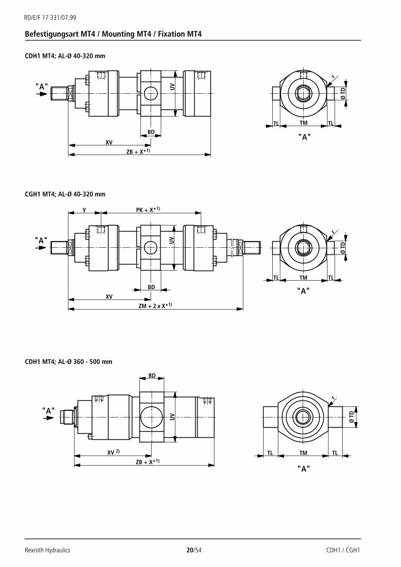
Befestigungsart MT4 / Mounting MT4 / Fixation MT4
CDH1 MT4; AL-Ø 40-320 mm
CGH1 MT4; AL-Ø 40-320 mm
CDH1 MT4; AL-Ø 360 - 500 mm

CDH1 / CGH1 21/54 Rexroth Hydraulics
RD/E/F 17 331/07.99
AL MM BD PK TD TL TM r UV X* XV XV XV Y ZB ZMØ Ø e8 js16 h13 min. Standard min. max.
40 38 120 30 20 95 1,6 88 22 1393) 150 136+X* 79 226 278
50 38 120 30 20 115 1,6 102 32 1473) 163 140+X* 87 233 294
63 48 133 35 20 130 2 120 47 166,53) 190 155+X* 100 262 333
80 58 146 40 25 145 2 140 58 1773) 206 160+X* 104 280 354
100 78 171 50 30 175 2 170 79 209,53) 249 185+X* 124 330 419
125 98 205 60 40 210 2,5 206 91 237,53) 283 207+X* 135 382 475
140 118 219 65 42,5 230 2,5 226 121 265,53) 326 220+X* 156 420 531
160 128 240 75 52,5 275 2,5 265 142 3053) 376 254+X* 185 475 610
180 138 264 85 55 300 2,5 292 158 3313) 410 272+X* 199 515 662
200 168 278 90 55 320 2,5 310 194 3443) 441 267+X* 205 535 688
220 135 326 100 60 370 2,5 355 155 4053) 482,5 327,5+X* 242 635 810
250 145 326 110 65 410 2,5 395 175 4293) 516,5 341,5+X* 266 659 858
280 165 375 130 70 450 2,5 425 336 469,53) 637,5 301,5+X* 282 744 939
320 195 431 160 90 510 2,5 490 180 502,53) 592,5 412,5+X* 287 815 1005
200360 220 240 – 220 135 525 4 525 458 2) 774 316+X* – 765 –
250
220400 250 260 – 240 140 585 4 585 484 2) 847 363+X* – 825 –
280250
450 280 280 – 260 150 655 4 655 486 2) 863 377+X* – 855 –
320280
500 320 300 – 280 155 775 4 775 510 2) 880 370+X* – 860 –
360
Maße MT4 (in mm) / Dimensions MT4 (in mm) / Encombrement MT4 (en mm)
X *+ – 2
Bemerkungen
Hauptmaße auf Seite 10 und 11AL = Kolben-ØMM = Kolbenstangen-ØX* = Hublänge1) = min. Hublänge "X*min."
beachten2) = Maß "XV" bei Bestellung immer
im Klartext angeben3) = XV Standard: Lage Schwenkzapfen
in Zylindermitte(ohne Angabe im Klartext)
Notes
For main dimensions, see pages 10 and 11AL = Piston ØMM = Piston rod ØX* = Stroke length1) = Please note the min. stroke length
"X*min."2) = Dimension "XV" must be indicated
in clear text in the order3) = XV standard: Position of the trunnion
in the centre of the cylinder(no indication in clear text)
Remarques
Cotes principales, voir pages 10 et 11AL = Ø du pistonMM = Ø de la tigeX* = Course1) = Tenir compte de la course mini
"X*mini"2) = Préciser la cote "XV" en clair dans
le texte de la commande3) = XV standard: Position du tourillion
au centre du vérin(ne pas préciseren clair dans le texte)
X *+ – 2 X *+ – 2
X *+ – 2 X *+ – 2 X *+ – 2
X *+ – 2
X *+ – 2 X *+ – 2
X *+ – 2
22282836364545565670709090
100100110110125125140140160160180180200200220
X *+ – 2 X *+ – 2 X *+ – 2 X *+ – 2

Rexroth Hydraulics 22/54 CDH1 / CGH1
RD/E/F 17 331/07.99
"A"
"A"
US
Ø SB
LH
L1
TS
ST
XS
ZB + X*1)
SS + X*1)
S1
S S
S1
2)
"A"
"A"
US
Ø SB
LH
L1
TS
ST
XS
ZM + 2 x X*1)
SS + X*1)
S1
S S
S1
Y PK + X*1)
2)
Befestigungsart MS2 / Mounting MS2 / Fixation MS2
CDH1 MS2; AL-Ø 40-320 mm
CGH1 MS2; AL-Ø 40-320 mm

CDH1 / CGH1 23/54 Rexroth Hydraulics
RD/E/F 17 331/07.99
Maße MS2 (in mm) / Dimensions MS2 (in mm) / Encombrement MS2 (en mm)
AL MM LH L1 PK S S1 SB SS ST TS US X* XS Y ZB ZMØ Ø H13 js13 -1 min.
40 45 89 120 30 15 11 50 32 110 135 – 114 79 226 278
50 55 106 120 35 17,5 11 45 37 130 155 – 124,5 87 233 294
63 65 125 133 40 20 13,5 49 42 150 180 – 142 100 262 333
80 75 145 146 50 25 17,5 52 47 180 220 2 151 104 280 354
100 90 175 171 60 30 22 61 57 210 255 3 179 124 330 419
125 105 208 205 70 35 26 75 67 255 305 – 200 135 382 475
140 115 228 219 85 42,5 30 70 72 290 350 19 230,5 156 420 531
160 135 267,5 240 105 52,5 33 65 77 330 400 44 272,5 185 475 610
180 150 296 264 115 57,5 40 69 92 360 440 50 296,5 199 515 662
200 160 315 278 125 62,5 40 73 97 385 465 56 307,5 205 535 688
220 185 362,5 326 155 77,5 45 75 102 445 530 100 367,5 242 635 810
250 205 402,5 326 155 77,5 52 75 112 500 600 100 391,5 266 659 858
280 225 437,5 375 155 77,5 52 124 127 530 630 171 407,5 282 744 939
320 255 500 431 190 95 62 125 142 610 730 85 440 287 815 1005
Bemerkungen
Hauptmaße auf Seite 10 und 11
AL = Kolben-Ø
MM = Kolbenstangen-Ø
X* = Hublänge1) = min. Hublänge "X*min."
beachten2) = Senkung 2 mm tief, für
Zylinderkopfschrauben;DIN 912 – Die Schrauben dürfennicht auf Scherspannung belastetwerden.Krafteinleitung über Paßleiste.
Notes
For main dimensions, see pages 10 and 11
AL = Piston Ø
MM = Piston rod Ø
X* = Stroke length1) = Please note the min. stroke
length "X*min."2) = Counterbore 2 mm deep for socket
head cap screws;DIN 912 – Screws must not besubjected to shear force.Keyed connections should be used.
Remarques
Cotes principales, voir pages 10 et 11
AL = Ø du piston
MM = Ø de la tige
X* = Course1) = Tenir compte de la course mini
"X*mini"2) = Chanfrein de 2 mm, pour
passage de vis.DIN 912 – Les vis ne doivent pasêtre soumises à des contraintes decisaillement.Alignement des forces par lamellesde réglage.
22282836364545565670709090
100100110110125125140140160160180180200200220

Rexroth Hydraulics 24/54 CDH1 / CGH1
RD/E/F 17 331/07.99
1)
EM
Ø C
K
KK2)
Ø b
AW
LE
CA
L1
C
Schwenkkopf CSA (in mm) / Plain clevis CSA (in mm) / Tenon à bague CSA (en mm)
AL Typ Material-Nr. AW b C CA CK EM KK LE L1 m 3)
Material no.Ø référence H11 -0,4 kg
40 CSA 16 00303150 17 28 56 50 25 23 M16x1,5 25 80 0,43
50 CSA 22 00303151 23 34 64 60 30 28 M22x1,5 30 94 0,7
63 CSA 28 00303152 29 44 78 70 35 30 M28x1,5 40 112 1,1
80 CSA 35 00303153 36 55 94 85 40 35 M35x1,5 45 135 2,0
100 CSA 45 00303154 46 70 116 105 50 40 M45x1,5 55 168 3,3
125 CSA 58 00303155 59 87 130 130 60 60 M58x1,5 65 200 5,5
140 CSA 65 00303156 66 93 154 150 70 55 M65x1,5 75 232 8,6
160 CSA 80 00303157 81 125 176 170 80 60 M80x2 80 265 12,2
180 CSA100 00303158 101 143 206 210 90 65 M100x2 90 323 21,5
200 CSA110 00303159 111 153 230 235 100 70 M110x2 105 360 27,5
Bemerkungen
AL = Kolben-Ø1) = Schmiernippel Kegelkopf
Form A nach DIN 71 4122) = Der Schwenkkopf muß immer gegen
die Schulter der Kolbenstange ge-schraubt werden
3) m = Masse Schwenkkopf
Notes
AL = Piston Ø1) = Cone head grease nipple
form A to DIN 71 4122) = The plain clevis must always be
screwed to the piston rod threadstop
3) m = Weight of the plain clevis
Remarques
AL = Ø de piston1) = Graisseur à tête sphérique,
forme A selon DIN 71 4122) = Le tenon à bague doit toujours être
vissé sur l'épaulement de la tige3) m = Masse du tenon à bague

CDH1 / CGH1 25/54 Rexroth Hydraulics
RD/E/F 17 331/07.99
EU
EN
Ø C
NA
X
KK3)
Ø b
ZZ
LFCH
L1
C
1)
2) 2)
5)
C
b
KK3)
LFCH
L1
ZZ
EU
EN
Ø C
NA
X
Gelenkkopf CGA (in mm) / Self-aligning clevis CGA (in mm) / Tenon à rotule CGA (en mm)
AL Typ Material-Nr. AX b C CH CN EN EU KK L1 LF Z m 4)
Material no.Ø référence -0,4 kg
40 CGA 16 00303125 17 28 56 50 25-0,010 20-0,12 23 M16x1,5 80 25 8° 0,43
50 CGA 22 00303126 23 34 64 60 30-0,010 22-0,12 28 M22x1,5 94 30 7° 0,7
63 CGA 28 00303127 29 44 78 70 35-0,012 25-0,12 30 M28x1,5 112 40 7° 1,1
80 CGA 35 00303128 36 55 94 85 40-0,012 28-0,12 35 M35x1,5 135 45 7° 2,0
100 CGA 45 00303129 46 70 116 105 50-0,012 35-0,12 40 M45x1,5 168 55 7° 3,3
125 CGA 58 00303130 59 87 130 130 60-0,015 44-0,15 50 M58x1,5 200 65 7° 5,5
140 CGA 65 00303131 66 93 154 150 70-0,015 49-0,15 55 M65x1,5 232 75 6° 8,6
160 CGA 80 00303132 81 125 176 170 80-0,015 55-0,15 60 M80x2 265 80 6° 12,2
180 CGA100 00303133 101 143 206 210 90-0,020 60-0,20 65 M100x2 323 90 6° 21,5
200 CGA110 00303134 111 153 230 235 100-0,020 70-0,20 70 M110x2 360 105 7° 27,5
220 CGA120 00303135 125 176 265 265 110-0,020 70-0,20 80 M120x3 407,5 115 6° 40,7
250 CGA120 00303135 125 176 265 265 110-0,020 70-0,20 80 M120x3 407,5 115 6° 40,7
280 CGA130 00303136 135 188 340 310 120-0,020 85-0,20 90 M130x3 490 140 6° 76,4
320 – – – – – – – – – – – – – –
360 CGA216 – 131 200 400 425 160-0,025 105-0,25 120 M150x3 665 255 4° 197
400 CGA218 – 153 210 450 490 180-0,030 105-0,25 130 M160x4 775 290 4° 281
450 CGA220 – 170 240 500 535 200-0,030 130-0,30 150 M180x4 845 320 4° 386
500 CGA222 – 185 270 560 590 220-0,035 135-0,30 160 M200x4 940 360 4° 523
BemerkungenAL = Kolben-Ø1) = Schmiernippel Kegelkopf
Form A nach DIN 71 4122) = zugehöriger Bolzen-Ø m6;
zugehöriger Bolzen-Ø j6 beiwartungsfreiem Gelenklager
3) = Der Gelenkkopf muß immer gegendie Schulter der Kolbenstange ge-schraubt werden
4) m = Masse Gelenkkopf5) = Flachschmiernippel DIN 3404-A
Bei Kolben-Ø 360 bis 500 mm Standard
NotesAL = Piston Ø1) = Cone head grease nipple
form A to DIN 71 4122) = Associated pin Ø m6;
associated pin Ø j6 withmaintenance free self-aligning clevis
3) = The self-aligning clevis must alwaysbe screwed to the piston rod threadstop
4) m = Weight of the self-aligning clevis5) = Flanged grease nipple DIN 3404-A
For piston Ø 360 to 500 mm as standard
RemarquesAL = Ø de piston1) = Graisseur à tête sphérique,
forme A selon DIN 71 4122) = Tolérance sur le Ø de l'axe: m6;
Tolérance sur le Ø de l‘axe : j6 avecrotule sans entretien
3) = Le tenon à rotule doit toujours êtrevissé sur l'épaulement de la tige
4) m = Masse du tenon à rotule5) = Graisseur à tête plate DIN 3404-A
Standard pour Ø de piston360 à 500 mm
AL-Ø 40-280 mm AL-Ø 360-500 mm

Rexroth Hydraulics 26/54 CDH1 / CGH1
RD/E/F 17 331/07.99
EU
EN
Ø C
NA
X
KK
Ø b
ZZ
LFCH
L1
C
1)
L2MA
3)
2)
Gelenkkopf CGAK (in mm) / Self-aligning clevis CGAK (in mm) / Tenon à rotule CGAK (en mm)
AL Typ Material-Nr. AX b C CH CN EN EU KK L1 L2 LF MA3) Z m 4)
Material no.Ø référence -0,4 Nm kg
40 CGAK 16 00303162 17 28 56 50 25-0,010 20-0,12 23 M16x1,5 80 20 25 9 8° 0,43
50 CGAK 22 00303163 23 34 64 60 30-0,010 22-0,12 28 M22x1,5 94 22 30 20 7° 0,7
63 CGAK 28 00303164 29 44 78 70 35-0,012 25-0,12 30 M28x1,5 112 27 40 20 7° 1,1
80 CGAK 35 00303165 36 55 94 85 40-0,012 28-0,12 35 M35x1,5 135 35 45 40 7° 2,0
100 CGAK 45 00303166 46 70 116 105 50-0,012 35-0,12 40 M45x1,5 168 42 55 80 7° 3,3
125 CGAK 58 00303167 59 87 130 130 60-0,015 44-0,15 50 M58x1,5 200 54 65 160 7° 5,5
140 CGAK 65 00303168 66 93 154 150 70-0,015 49-0,15 55 M65x1,5 232 57 75 160 6° 8,6
160 CGAK 80 00303169 81 125 176 170 80-0,015 55-0,15 60 M80x2 265 66 80 160 6° 12,2
180 CGAK100 00321655 101 143 206 210 90-0,020 60-0,20 65 M100x2 323 76 90 160 6° 21,5
200 CGAK110 00321691 111 153 230 235 100-0,020 70-0,20 70 M110x2 360 85 105 300 7° 27,5
220 CGAK120 00321621 125 176 265 265 110-0,020 70-0,20 80 M120x3 407,5 96 115 500 6° 40,7
250 CGAK120 00321621 125 176 265 265 110-0,020 70-0,20 80 M120x3 407,5 96 115 500 6° 40,7
280 CGAK130 00322015 135 188 340 310 120-0,020 85-0,20 90 M130x3 490 102 140 500 6° 76,4
320 – – – – – – – – – – – – – – – –
Bemerkungen
AL = Kolben-Ø1) = Schmiernippel Kegelkopf
Form A nach DIN 71 4122) = zugehöriger Bolzen-Ø m6
zugehöriger Bolzen-Ø j6 beiwartungsfreiem Gelenklager
3) MA = AnzugsmomentDer Gelenkkopf muß immer gegendie Schulter der Kolbenstange ge-schraubt werden. Danach müssendie Klemmschrauben mit dem an-gegebenen Anzugsmoment ange-zogen werden.
4) m = Masse Gelenkkopf
Notes
AL = Piston Ø1) = Cone head grease nipple
form A to DIN 71 4122) = Associated pin Ø m6;
associated pin Ø j6 withmaintenance free self-aligning clevis
3) MA = Tightening torqueThe self-aligning clevis must alwaysbe screwed to the piston rod threadstop. Subsequently, the clampingscrews have to be tightened to thespecified torque.
4) m = Weight of the self-aligning clevis
Remarques
AL = Ø de piston1) = Graisseur à tête sphérique,
forme A selon DIN 71 4122) = Tolérance sur le Ø de l'axe: m6;
Tolérance sur le Ø de l‘axe : j6 avecrotule sans entretien
3) MA = Couple de serrageLe tenon à rotule doit toujours êtrevissé sur l'épaulement de la tige. Lesvis de serrage doivent être serréesau couple de serrage spécifié.
4) m = Masse du tenon à rotule

CDH1 / CGH1 27/54 Rexroth Hydraulics
RD/E/F 17 331/07.99
EU
EN
Ø C
NA
X
KK3)
Ø b
ZZ
LFCH
L1
C
1)
L2MA
3)
2)
Gelenkkopf CGAS (in mm) / Self-aligning clevis CGAS (in mm) / Tenon à rotule CGAS (en mm)
AL Typ Material-Nr. AX b C CH CN EN EU KK L1 L2 LF MA3) Z m 4)
Material no.Ø référence -0,4 Nm kg
40 CGAS 25 00303137 30 28 56 65 25-0,010 20-0,12 23 M18x2 95 24 25 20 8° 0,65
50 CGAS 30 00303138 35 34 64 75 30-0,010 22-0,12 28 M24x2 109 27 30 20 7° 1,0
63 CGAS 35 00303139 45 44 78 90 35-0,012 25-0,12 30 M30x2 132 33 40 40 7° 1,3
80 CGAS 40 00303140 55 55 94 105 40-0,012 28-0,12 35 M39x3 155 39 45 80 7° 2,4
100 CGAS 50 00303141 75 70 116 135 50-0,012 35-0,12 40 M50x3 198 45 55 80 7° 4,1
125 CGAS 60 00303142 95 87 130 170 60-0,015 44-0,15 50 M64x3 240 59 65 160 7° 6,5
140 CGAS 70 00303143 110 105 154 195 70-0,015 49-0,15 55 M80x3 278 65 75 160 6° 9,5
160 CGAS 80 00303144 120 125 176 210 80-0,015 55-0,15 60 M90x3 305 76 80 300 6° 16
180 CGAS 90 00303145 140 150 206 250 90-0,020 60-0,20 65 M100x3 363 81 90 300 5° 28
200 CGAS100 00303146 150 170 230 275 100-0,020 70-0,20 70 M110x4 400 86 105 300 7° 34
220 CGAS110 00303147 160 180 265 300 110-0,020 70-0,20 80 M120x4 442,5 97 115 500 6° 44
250 CGAS110 00303147 160 180 265 300 110-0,020 70-0,20 80 M120x4 442,5 97 115 500 6° 44
280 CGAS120 00303148 190 210 340 360 120-0,020 85-0,20 90 M150x4 540 112 140 500 6° 75
320 CGAS140 00317314 200 230 380 420 140-0,025 90-0,25 110 M160x4 620 123 185 1000 7° 160
Bemerkungen
AL = Kolben-Ø1) = Schmiernippel Kegelkopf
Form A nach DIN 71 4122) = zugehöriger Bolzen-Ø m6;
zugehöriger Bolzen-Ø j6 beiwartungsfreiem Gelenklager
3) MA = AnzugsmomentDer Gelenkkopf muß immer gegendie Schulter der Kolbenstange ge-schraubt werden. Danach müssendie Klemmschrauben mit dem an-gegebenen Anzugsmoment ange-zogen werden.
4) m = Masse Gelenkkopf
Notes
AL = Piston Ø1) = Cone head grease nipple
form A to DIN 71 4122) = Associated pin Ø m6;
associated pin Ø j6 withmaintenance free self-aligning clevis
3) MA = Tightening torqueThe self-aligning clevis must alwaysbe screwed to the piston rod threadstop. Subsequently, the clampingscrews have to be tightened to thespecified torque.
4) m = Weight of the self-aligning clevis
Remarques
AL = Ø de piston1) = Graisseur à tête sphérique,
forme A selon DIN 71 4122) = Tolérance sur le Ø de l'axe: m6;
Tolérance sur le Ø de l‘axe : j6 avecrotule sans entretien
3) MA = Couple de serrageLe tenon à rotule doit toujours êtrevissé sur l'épaulement de la tige. Lesvis de serrage doivent être serréesau couple de serrage spécifié.
4) m = Masse du tenon à rotule

Rexroth Hydraulics 28/54 CDH1 / CGH1
RD/E/F 17 331/07.99
Knickung / Buckling / Flambage
Calculations for buckling are carried outusing the following formulas:1. Calculation according to Euler
2. Calculation according to Tetmajer
Explanation:
E = Modulus of elasticity in N/mm2
= 2.1 x 10⁵ for steelI = Moment of inertia in mm4 for circular
cross-sectional area
ν = 3.5 (safety factor)LK = Free buckling length in mm (depend-
ing on mounting type, see sketches A,B, C on page 29).
d = Piston rod Ø in mmλ = Slenderness ratio
4 • LK E= λg = π d 0.8 • Re
Re = Yield strength of the piston rodmaterial
Example:
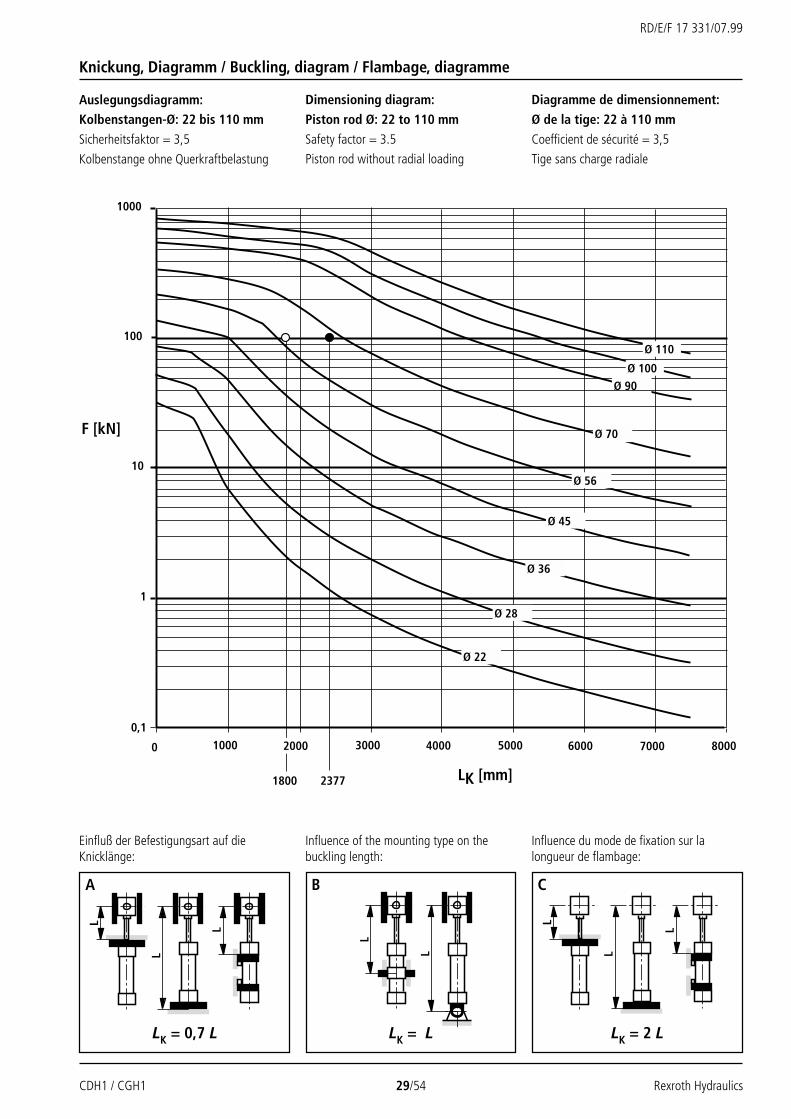
A differential cylinder of series CDH1… is tobe calculated with plain bearings on bothends for a pushing force F of 100 kN (10200kp) at an operating pressure of 120 bar. Thestroke length is to be 900 mm.A first estimation of the free buckling lengthLK provides:LK = L = 2 x stroke length = 1800 mm(see page 29, fig. B)The diagram (page 29) shows that a pistonrod Ø of 70 mm is sufficient.On the basis of the required area A1 req., theselection table on page 6 indicates anassociated piston Ø of 125 mm.A1 req. = F / p = 10200 kp/120 barA1 req. = 85 cm2 (condition: A1 req. < A1)The actual free buckling length can now bedetermined from the dimension tables onpage 15 (mounting type MP5) and page 25(self-aligning clevis CGA 58) as follows:
LK = L, i.e. the distance between the bearingswith the piston rod being extended.
LK = XO + stroke length + stroke length + CHLK = 447 + 900 + 900 + 130LK = 2377 mm.
The diagram on page 29 shows that theselected piston rod Ø of 70 mm is sufficientand that the required pushing force can beprovided.
Le calcul de flambage se fait à l'aide desformules suivantes:1. Calcul selon Euler
2. Calcul selon Tetmajer
Explication:
E = Module d'élasticité en N/mm2
= 2,1 x 10⁵ pour l'acierI = Moment d'inertie géométrique en
mm4 pour une section circulaire
ν = 3,5 (coefficient de sécurité)LK = Longueur libre de flambage en mm
(en fonction du mode de fixation,voir les figures A, B, C page 29).
d = Ø de la tige en mmλ = Degré d'élancement
4 • LK E= λg = π d 0,8 • Re
Re = Limite d'élasticité du matériau de latige
Exemple:
On cherche un vérin différentiel de la sérieCDH1…, avec palier à rotule aux deuxextrémités pour une poussée F de 100 kN(10200 kp) à une pression de service de 120bar. La course doit être de 900 mm.La première estimation de la longueur librede flambage LK est:LK = L = 2 x course = 1800 mm(voir page 29 Fig. B)Le diagramme (page 29) montre qu'un Ø de70 mm pour la tige du piston suffit.Par le calcul de la section requise A1 req. letableau de sélection page 6 donne un Ø depiston de 125 mm.A1 req. = F / p = 10200 kp/120 barA1 req. = 85 cm2 (condition: A1 req. < A1)La longueur libre de flambage réelle peutalors être déterminée à partir des tableauxde cotes page 15 (type de fixation MP5) etpage 25 (tenon à rotule CGA 58) comme suit:
LK = L, c.-à-d. la distance entre les deuxpaliers, la tige étant sortie.
LK = XO + course + course + CHLK = 447 + 900 + 900 + 130LK = 2377 mm.
Le diagramme de la page 29 montre que leØ de 70 mm selectionné pour la tige de pistonsuffit et que le vérin peut fournir la pousséerequise.
Die Berechnung auf Knickung wird mit denfolgenden Formeln durchgeführt:1. Berechnung nach Euler
2. Berechnung nach Tetmajer
Erläuterung:E = Elastizitätsmodul in N/mm2
= 2,1 x 10⁵ für StahlI = Flächenträgheitsmoment in mm4 für
Kreisquerschnitt
ν = 3,5 (Sicherheitsfaktor)LK = freie Knicklänge in mm (abhängig
von der Befestigungsart siehe dieSkizzen A, B, C Seite 29).
d = Kolbenstangen-Ø in mmλ = Schlankheitsgrad
4 • LK E= λg = π d 0,8 • Re
Re = Streckgrenze des Kolbenstangen-materials
Beispiel:
Gesucht wird ein Differentialzylinder der Bau-reihe CDH1…, beidseitig mit Gelenklager füreine Druckkraft F von 100 kN (10200 kp) beieinem Betriebsdruck von 120 bar. Die Hub-länge soll 900 mm betragen.Die erste Schätzung der freien Knicklänge LKergibt:LK = L = 2 x Hublänge = 1800 mm(siehe Seite 29 Abb. B)Aus dem Diagramm (Seite 29) ist ersichtlich,daß ein Kolbenstangen-Ø von 70 mm aus-reichend ist.Über die Berechnung der erforderlichen Flä-che A1 erf. ergibt sich aus der Auswahltabelleauf Seite 6 der zugehörige Kolben-Ø von 125 mm.A1 erf. = F / p = 10200 kp/120 barA1 erf. = 85 cm2 (Bedingung: A1 erf. < A1)Die tatsächliche freie Knicklänge kann nunaus den Maßtabellen auf Seite 15(Befestigungsart MP5) und Seite 25 (Gelenk-kopf CGA 58) wie folgt ermittelt werden:
LK = L, also der Abstand zwischen den bei-den Lagerpunkten bei ausgefahrenerKolbenstange.
LK = XO + Hublänge + Hublänge + CHLK = 447 + 900 + 900 + 130LK = 2377 mm.
Das Diagramm auf Seite 29 zeigt, daß derausgewählte Kolbenstangen-Ø von 70 mmausreichend ist und die erforderliche Druck-kraft aufgebracht werden kann.
d 4 • π= = 0,0491 • d4
64d 4 • π
= = 0,0491 • d4
64d 4 • π
= = 0,0491 • d4
64
d 2 • π (335-0,62•λ)F = wenn λ ≤ λg
4 • ν
π 2 • E • IF = wenn λ > λg
ν • LK2
d 2 • π (335-0,62•λ)F = wenn λ ≤ λg
4 • ν
π 2 • E • IF = wenn λ > λg
ν • LK2
d 2 • π (335-0,62•λ)F = wenn λ ≤ λg
4 • ν
π 2 • E • IF = wenn λ > λg
ν • LK2
CDH1 / CGH1 29/54 Rexroth Hydraulics
RD/E/F 17 331/07.99
L
L
L
L
L
L
L
L
Ø 90
100
1000
10
1
20000 4000 5000 60003000 7000 8000
Ø 70
Ø 22
Ø 110
Ø 28
Ø 45
Ø 36
Ø 56
0,11000
Ø 100
1800 2377
F [kN]
LK [mm]
A
LK = 0,7 L
B C
LK = L LK = 2 L
Knickung, Diagramm / Buckling, diagram / Flambage, diagramme
Auslegungsdiagramm:Kolbenstangen-Ø: 22 bis 110 mm
Sicherheitsfaktor = 3,5
Kolbenstange ohne Querkraftbelastung
Dimensioning diagram:
Piston rod Ø: 22 to 110 mm
Safety factor = 3.5
Piston rod without radial loading
Diagramme de dimensionnement:
Ø de la tige: 22 à 110 mm
Coefficient de sécurité = 3,5
Tige sans charge radiale
Einfluß der Befestigungsart auf dieKnicklänge:
Influence of the mounting type on thebuckling length:
Influence du mode de fixation sur lalongueur de flambage:

Rexroth Hydraulics 30/54 CDH1 / CGH1
RD/E/F 17 331/07.99
Ø 220
Ø 250
Ø 280
Ø 360
Ø 180
Ø 320
1000
100
10
0 800040002000 14000120006000 10000
10000
Ø 200
Ø 140
Ø 160
Ø 125
F [kN]
LK [mm]
Auslegungsdiagramm:Kolbenstangen-Ø: 125 bis 360 mm
Sicherheitsfaktor = 3,5
Kolbenstange ohne Querkraftbelastung
Bemerkungen
Die beiden Diagramme stellen die zulässigeDruckkraft F als eine Funktion der freienKnicklänge LK für die Kolbenstangen-Ødieser Baureihe dar.
Die Diagramme sind nur für vertikaleEinbaufälle gültig. Horizontale Einbaufälleauf Anfrage.
Notes
The two diagrams represent the permissiblepushing force F as a function of the freebuckling length LK for the piston rod Ø ofthis series.
These diagrams only refer to verticalinstallation. For horizontal installation,please consult us.
Remarques
Les deux diagrammes représentent lapoussée F admissible en fonction de lalongueur libre de flambage LK pour les Ødes tiges de cette série.
Les diagrammes ne sont valables que pourun montage vertical. Pour un montagehorizontal, veuillez nous consulter.
Dimensioning diagram:Piston rod Ø: 125 to 360 mm
Safety factor = 3.5
Piston rod without radial loading
Diagramme de dimensionnement:
Ø de la tige: 125 à 360 mm
Coefficient de sécurité = 3,5
Tige sans charge radiale
Knickung, Diagramm / Buckling, diagram / Flambage, diagramme

CDH1 / CGH1 31/54 Rexroth Hydraulics
RD/E/F 17 331/07.99
M
m
ps
v
v1 v2
p
ssd
v1
v2
p
ssd
m
m
α α m
m
α α m
m
α α
Formules:
m = Masse déplacée en kgv = Vitesse de déplacement en m/skv = Voir tableau page 32
Sortie tige:
Rentrée tige:
pS = Pression du système en barA1 = Section du piston en cm2 (voir page 6)A3 = Section annulaire en cm2 (voir page 6)α = Angle en degrés par rapport à
l'horizontale
Formulas:
m = Moved mass in kgv = Stroke velocity in m/skv = See table page 32
Extending:
Retracting:
pS = System pressure in barA1 = Piston area in cm2 (see page 6)A3 = Annulus area in cm2 (see page 6)α = Angle in degrees with reference
to the horizontal plane
Formeln:
m = bewegte Masse in kgv = Hubgeschwindigkeit in m/skv = siehe Tabelle Seite 32
Ausfahren:
Einfahren:
pS = Systemdruck in barA1 = Kolbenfläche in cm2 (siehe Seite 6)A3 = Ringfläche in cm2 (siehe Seite 6)α = Winkel zur Horizontalen in Grad
Self-regulating end positioncushioning
The objective is to reduce the speed of amoving mass, whose center of gravity lieson the cylinder axis, to a level, at whichneither the cylinder nor the machine, intowhich the cylinder is installed, can be dam-aged.The self-regulating end position cushioningproduces a controlled deceleration in bothend positions. The effective cushioninglength adjusts automatically to the currentreqirements.
The calculation depends on the factors ofweight, velocity, system pressure and in-stallation position. Therefore, the variableDm is to be calculated from weight andspeed, the variable Dp from system pres-sure and installation position. These vari-ables are then used to verify the permissi-ble cushioning performance in the "cush-ioning capacity" diagram. The intersectionpoint of the variables Dm and Dp mustalways be below the cushioning capacitycurve of the selected cylinder.
Selbsteinstellende Endlagen-dämpfung
Ziel ist es, die Geschwindigkeit einerbewegten Masse, deren Schwerpunkt inder Zylinderachse liegt, auf ein Niveau zuverringern, bei der weder der Zylinder nochdie Maschine, in der der Zylinder eingebautist, geschädigt wird.Die selbsteinstellende Endlagendämpfungbewirkt ein kontrolliertes Verzögern(Abbremsen) in beiden Endlagen. Diewirksame Dämpfungslänge paßt sichhierbei selbständig den Anforderungen an.
Die Berechnung ist von den FaktorenMasse, Geschwindigkeit, Systemdruck undEinbaulage abhängig. Deshalb werden ausMasse und Geschwindigkeit die KennzahlDm und aus Systemdruck und Einbaulagedie Kennzahl Dp ermittelt. Mit diesenbeiden Kennzahlen wird im Diagramm"Dämpfungskapazität" die zulässigeDämpfungsleistung überprüft. Der Schnitt-punkt der Kennzahlen Dm und Dp mußimmer unterhalb der Dämpfungskapazitäts-kurve des ausgewählten Zylinders liegen.
Amortissement de fin de courseadaptif
La vitesse de déplacement d'une massedont le centre de gravité se trouve sur l'axedu vérin doit être réduite à un niveauauquel ni le vérin ni la machine dans la-quelle le vérin est installé, ne soient en-dommagés.L'amortissement de fin de course adaptifproduit une décélération contrôlée (frei-nage) aux deux extrémités du vérin. Lalongueur effective d'amortissement s'ajusteautomatiquement aux conditionsexistantes.
Le calcul dépend des facteurs masse, vi-tesse, pression du système et position demontage. A cet effet, la valeur Dm est dé-terminée à partir de la masse et de la vi-tesse, et la valeur Dp à partir de la pressiondu système et de la position de montage. Al'aide de ces deux valeurs on peut vérifierla capacité d'amortissement dans le dia-gramme admissible "capacité d'amortisse-ment". Le point d'intersection des valeursDm et Dp doit toujours être en dessous de lacourbe de capacité d'amortissement duvérin sélectionné.
Endlagendämpfung / End position cushioning / Amortissement de fin de course
mDm = ; K = kv ( 0,5-v )10K
mDm = ; K = kv ( 0,5-v )10K
mDm = ; K = kv ( 0,5-v )10K
m • 9,81 • sinαDp = pS – A1 • 10m • 9,81 • sinαDp = pS – A1 • 10
m • 9,81 • sinαDp = pS – A1 • 10
m • 9,81 • sinαDp = pS + A3 • 10m • 9,81 • sinαDp = pS + A3 • 10
m • 9,81 • sinαDp = pS + A3 • 10

Rexroth Hydraulics 32/54 CDH1 / CGH1
RD/E/F 17 331/07.99
1000000
100000
10000
1000
100
100 20 40 60 80 100 120 140 160 180 200
Ø320Ø280Ø250Ø220Ø200Ø180Ø160Ø140
Ø125Ø100Ø80Ø63Ø50Ø40
1
Endlagendämpfung / End position cushioning / Amortissement de fin de course
Dämpfungskapazität: Ausfahren Cushioning capacity: Extending Capacité d'amortissement: sortie tige
AL/MM Ø mm 40 50 63 80 100 125 140 160 180 200 220 250 280 320
kv 1 2,85 2,97 2,56 2,82 3,51 3,02 2,53 2,65 2,91 2,76 2,85 2,95 3,11 3,13
kv 2 3,1 3,25 2,85 2,85 3,52 2,91 2,53 2,93 2,95 2,95 2,93 3,1 3,12 3,07
kv 3 2,95 3,1 2,73 3,1 3,51 2,95 2,51 2,91 2,95 2,91 2,93 2,93 3,15 3,25
Dm
→
Dp →
Bemerkungen1) Ist bei Standardanwendungen der berech-
nete Schnittpunkt von Dm und Dp inner-halb der gekennzeichneten Fläche, so emp-fehlen wir den Zylinder ohneEndlagendämpfung auszuführen.
1)
Note1) If, for standard applications, the calculated
section point from Dm and Dp is within theindicated area, then we recommend thata cylinder is used without end positiondamping.
Remarques1) Si, pour une application standard, le point
d‘intersection calculé de Dm et Dp se trouvedans la plage grisée, nous recommandonsde choisir un vérin sans amortissement defin de course.

CDH1 / CGH1 33/54 Rexroth Hydraulics
RD/E/F 17 331/07.99
10000000
1000000
100000
10000
1000
100
1040 80 120 160 200 24020 60 100 140 180 220
2Ø320/200Ø280/180Ø250/160Ø220/140
Ø200/125Ø180/110Ø160/100Ø140/90
Ø125/70Ø100/56Ø80/45Ø60/36Ø50/28Ø40/22
10000000
1000000
100000
10000
1000
100
1040 80 120 160 200 24020 60 100 140 180 220
3
Ø125/90Ø100/70Ø80/56Ø63/45Ø50/36Ø40/28
Ø320/220Ø280/200Ø250/180Ø220/160
Ø200/140Ø180/125Ø160/110Ø140/100
Endlagendämpfung / End position cushioning / Amortissement de fin de course
Capacité d'amortissement: rentrée tigeDämpfungskapazität: Einfahren Cushioning capacity: RetractingD
m →
Dp →
Dm
→
Dp →
1)
1)
Bemerkungen1) Ist bei Standardanwendungen der berech-
nete Schnittpunkt von Dm und Dp inner-halb der gekennzeichneten Fläche, so emp-fehlen wir den Zylinder ohneEndlagendämpfung auszuführen.
Note1) If, for standard applications, the calculated
section point from Dm and Dp is within theindicated area, then we recommend thata cylinder is used without end positiondamping.
Remarques1) Si, pour une application standard, le point
d‘intersection calculé de Dm et Dp se trouvedans la plage grisée, nous recommandonsde choisir un vérin sans amortissement defin de course.

Rexroth Hydraulics 34/54 CDH1 / CGH1
RD/E/F 17 331/07.99
PJ + X*
X1
Y
X2X2 X1
Y PK + X*
w
c Ød 3
d1
w
w Ød 3
d1
Flanschanschlüsse / Flange connections / Brides de raccordement
CDH1: AL-Ø 40-320 mm
CGH1: AL-Ø 40-320 mm
Lochbild für Rechteckflansch nach ISO 6162 Tabelle 2( SAE 6000 PSI)Hole pattern for rectangular flanges to ISO 6162 table 2( SAE 6000 PSI)
Impact de raccordement pour bride rectangulaire selonISO 6162 tableau N° 2 ( SAE 6000 PSI)
Lochbild für Quadratflansch nach ISO 6164 Tabelle 2Hole pattern for square flanges to ISO 6164 table 2
Impact de raccordement pour bride carrée selontableau N° 2 ISO 6164

CDH1 / CGH1 35/54 Rexroth Hydraulics
RD/E/F 17 331/07.99
AL ISO 6162 Tab.2 (400 bar) ( SAE 6000 PSI) ISO 6164 Tab.2 (400 bar)
Ø Y PJ X1 X2 d3 d34) c w d1 t1
1) t12) p3) Y PJ X1 d3 w d1 t1
1) t12) p3)
PK Ø Ø ±0,25 ±0,25 PK X2 Ø ±0,25
40 – – – – – – – – – – – – 78 122 40,5 10 24,7 M6 12,5 10 400
50 – – – – – – – – – – – – 86 122 48 10 24,7 M6 12,5 10 400
63 – – – – – – – – – – – – 99 135 57 13 29,7 M8 16 13 400
80 102,5 149 65 65 13 1/2“ 40,5 18,2 M8 16 14 400 103 148 67 13 29,7 M8 16 15 400
100 124 171 80,5 80,5 13 1/2“ 40,5 18,2 M8 16 16 400 123 173 81,5 19 35,4 M8 16 16 400
125 135 205 97,5 97,5 19 3/4“ 50,8 23,8 M10 20 20 400 131,5 212 99 25 43,8 M10 20 20 400
140 152 227 107 107 25 1“ 57,2 27,8 M12 24 24 400 152 227 109 25 43,8 M10 20 20 400
160 184 242 127 127 25 1“ 57,2 27,8 M12 24 24 400 182,5 245 128 32 51,6 M12 24 24 400
180 199 264 139,5 139,5 32 1 1/4“ 66,6 31,8 M14 26 26 400 199 264 142 32 51,6 M12 24 24 400
200 205 278 149 149 32 1 1/4“ 66,6 31,8 M14 26 26 400 201,5 285 149,5 38 60,1 M16 30 30 400
220 242 326 168 168 38 1 1/2“ 79,3 36,5 M16 30 30 400 242 326 171 38 60,1 M16 30 30 400
250 266 326 189 189 38 1 1/2“ 79,3 36,5 M16 30 30 400 266 326 192 38 60,1 M16 30 30 400
280 282 375 204 204 38 1 1/2“ 79,3 36,5 M16 30 30 400 282 375 207 38 60,1 M16 30 30 400
320 287 431 236 236 51 2“ 96,8 44,5 M20 36 36 400 287 431 240 51 69,3 M16 30 30 400
360 280 418 200 217 51 2“ 96,8 44,5 M20 36 36 400 – – – – – – – – –
400 340 418 221 251 51 2“ 96,8 44,5 M20 36 36 400 – – – – – – – – –
450 340 448 256 276 51 2“ 96,8 44,5 M20 36 36 400 – – – – – – – – –
500 345 448 290 314 51 2“ 96,8 44,5 M20 36 36 400 – – – – – – – – –
Bemerkungen
Hauptmaße siehe Seite 10 und 11AL = Kolben-ØX* = Hublänge1) = Gewindetiefe für Dichtungs-
ausführung M, T, K, S und C2) = Gewindetiefe für Dichtungs-
ausführung A und B3) = max. Betriebsdruck für zugehörige
Flansche in bar4) = Flanschlochbild nach ISO 6162 Tab.2
entspricht Flanschlochbild nachSAE 6000 PSI
Maße (in mm) / Dimensions (in mm) / Encombrement (en mm)
Flanschanschlüsse / Flange connections / Brides de raccordement
Notes
For main dimensions see pages 10 and 11AL = Piston ØX* = Stroke length1) = Thread depth for seal versions
M, T, K, S and C2) = Thread depth for seal versions
A and B3) = Max. operating pressure for
associated flanges in bar4) = Flange hole pattern to ISO 6162 Tab.2
relates to a flange hole pattern toSAE 6000 PSI
Remarques
Cotes principales : voir pages 10 et 11AL = Ø de pistonX* = course1) = profondeur du filetage pour joints
types M, T, K, S et C2) = profondeur du filetage pour joints
types A et B3) = pression de service max. pour brides
correspondantes, en bar4) = l‘impact de raccordement pour bride
ISO 6162 tableau 2 correspond àl‘impact de raccordement pour brideSAE 6000 PSI

Rexroth Hydraulics 36/54 CDH1 / CGH1
RD/E/F 17 331/07.99
Wegemeßsystem / Position measuring system / Système de détection de position
Betriebsdruck: 250 bar
Analogausgang: 0 bis 10 VLastwiderstand: ≥ 5 kΩAuflösung: Unendlich
Analogausgang: 4 bis 20 mALastwiderstand: ≥ 100 kΩAuflösung: Unendlich
Digitalausgang:SSI 24 Bit Gray-kodiertAuflösung: 5 µm
Linearität (absolute Genauigkeit):≤ ±0,05 % (bezogen auf Meßlänge)min. ±0,05 mm
Reproduzierbarkeit:≤ ±0,001 % (bezogen auf Meßlänge)min. ±0,006 mm
Hysterese: ≤ 0,03 mm
Versorgungsspannung:24 V DC (± 25 % bei Analogausgang)Stromaufnahme: 80 mARestwelligkeit: ≤ 1 % s-s
24 V DC (+ 20 %/– 15 % bei Digital-ausgang)Stromaufnahme: 55 mARestwelligkeit: ≤ 1 % s-s
Schutzart:Rohr und Flansch: IP 67Sensorelektronik: IP 65
Betriebstemperatur:Sensorelektronik: -40 °C bis +65 °CMaßstab: -40 °C bis +85 °C
Temperaturkoeffizient:Spannung: 70 ppm/°CStrom: 90 ppm/°C
Das bis 500 bar druckfeste Wegmeßsystemarbeitet berührungslos und absolut. Grund-lage dieses Wegmeßsystems ist dermagnetostriktive Effekt. Dabei wird durch dasZusammentreffen zweier Magnetfelder einTorsionsimpuls ausgelöst. Dieser Impuls läuftauf dem Wellenleiter im Inneren des Maß-stabes vom Meßort zum Sensorkopf. Die Lauf-zeit ist konstant und nahezu temperatur-unabhängig. Sie ist proportional zur Positiondes Magneten und somit ein Maß für denWeg-Istwert und wird im Sensor in einen di-rekten Analog- oder Digitalausgang umge-wandelt.
This contactless and absolute positionmeasuring system is pressure-tight up to 500bar. Its function principle is based on themagnetrostrictive effect. In connection withthis, a torsion impulse is triggered off whentwo magnetic fields meet. This impulse isdirected from the point of measurement viathe waveguide inside the measuring scale tothe sensor head. The transit time is constantand virtually independent of temperature. Itis proportional to the position of the soleno-id and can therefore be used as a referencefor the actual position value and is convertedinto a direct analog or digital output in thesensor head.
Le système de détection de position, étanchejusqu'à 500 bar, fonctionne sans contact eten absolu sur le principe de l'effetmagnétostrictif. La rencontre de deux champsmagnétiques produit une impulsion qui,portée par le guide d'ondes placé à l'intérieurde la sonde, va du point de mesure à la têtede détection. Le temps de propagation estconstant et presque indépendant de latempérature; Il est proportionnel à la positionde l'électro-aimant, constituant ainsi uneréférence pour la recopie de position, et estconverti dans le capteur en une sortieanalogique ou numérique directe.
Technische Daten / Technical data / Données techniques
Operating pressure: 250 bar
Analog output: 0 bis 10 VLoad resistance: ≥ 5 kΩResolution: Infinite
Analog output: 4 bis 20 mALoad resistance: ≥ 100 kΩResolution: Infinite
Digital output:SSI 24 bit Gray-codedResolution: 5 µm
Linearity (absolute accuracy):≤ ±0,05 % (referred to measuring length)min. ±0,05 mm
Reproducibility:≤ ±0,001 % (referred to measuring length)min. ±0,006 mm
Hysteresis: ≤ 0,03 mm
Supply voltage:24 V DC (± 25 % with analog output)Power requirement: 80 mAResidual ripple content: ≤ 1 % s-s
24 V DC (+ 20 %/– 15 % with digitaloutput)Power requirement: 55 mAResidual ripple content: ≤ 1 % s-s
Type of insulation:Tube and flange: IP 67Sensor electronics: IP 65
Operation temperature:Sensor electronics: -40 °C bis +65 °CMeasuring scale: -40 °C bis +85 °C
Temperature coefficient:Voltage: 70 ppm/°CCurrent: 90 ppm/°C
Pression de service: 250 bar
Sortie analogique: 0 bis 10 VRésistance de charge: ≥ 5 kΩRésolution: Infini
Sortie analogique: 4 bis 20 mARésistance de charge: ≥ 100 kΩRésolution: Infini
Sortie numérique:SSI 24 bit code GrayRésolution: 5 µm
Linéarité (précision absolue):≤ ±0,05 % (par rapport à la longueur demesure) min. ±0,05 mm
Reproductibilité:≤ ±0,001 % (par rapport à la longueur demesure) min. ±0,006 mm
Hystérésis: ≤ 0,03 mm
Alimentation en courant:24 V DC (± 25 % pour sortie analogique)Consommation de courant: 80 mAOndulation résiduelle: ≤ 1 % s-s
24 V DC (+ 20 %/– 15 % pour sortienumérique)Consommation de courant: 55 mAOndulation résiduelle: ≤ 1 % s-s
Type de protection:Tuyau et bride: IP 67Electronique du capteur: IP 65
Température de service:Electronique du capteur: -40 °C bis +65 °CEchelle graduée: -40 °C bis +85 °C
Coefficient de température:Tension: 70 ppm/°CCourant: 90 ppm/°C

CDH1 / CGH1 37/54 Rexroth Hydraulics
RD/E/F 17 331/07.99
2 1
3 6
4 5
6
14
2
7
35
1)
1)
MP3, MP5 MF3, MF4, MT4, MS2
1) Für Analogausgang:6polige Amphenol -Leitungsdose Material-Nr. 00072231(Leitungsdose ist im Lieferumfang nichtenthalten, muß seperat bestellt werden)
Wegmeßsystem (Analogausgang)Gerätestecker (Ansicht auf Stiftseite)
Pos. measuring system (analogue output)Component plug (viewed on the pin side)
Système de mesure de position(sortie analogique)embase mâle fixe (broches face à soi)
Wegmeßsystem (Digitalausgang)Gerätestecker (Ansicht auf Stiftseite)
Pos. measuring system (digital output)Component plug (viewed on the pin side)
Système de mesure de position(sortie numérique)embase mâle fixe (broches face à soi)
Befestigungsarten / Mounting types / Types de fixation
1) Für Digitalausgang:7polige Amphenol -Leitungsdose Material-Nr. 00079551(Leitungsdose ist im Lieferumfang nichtenthalten, muß seperat bestellt werden)
1) For analogue output:6-pin Amphenol -Plug-in connector material no. 00072231(Plug-in connector is not included within thescope of supply, has to be ordered separately)
1) For digital output:7-pin Amphenol -Plug-in connector material no. 00079551(Plug-in connector is not included within thescope of supply, has to be ordered separately)
1) pour sortie analogique :connecteur femelle 6 broches Amphenolréférence 00072231(Le connecteur femelle n‘est pas inclusdans la fourniture et doit être commandéséparément)
1) pour sortie numérique :connecteur femelle 7 broches Amphenolréférence 00079551(Le connecteur femelle n‘est pas inclusdans la fourniture et doit être commandéséparément)
Wegemeßsystem / Position measuring system / Système de mesure de position
Anschlußbelegung / Connection allocation / Affectation des broches
Pin Kabel Signal / Strom Signal / SpannungPin Cable Signal / current Signal / voltage
broche câble signal / courant signal / tension
1 grau / grey / gris 4...20 mA 0 - 10 V
2 rosa / pink / rose Gnd Gnd
3 gelb / yellow / jaune n. c. 10 - 0 V
4 grün / green / vert n. c. Gnd
5 braun / brown / brun +24 V DC (±25%) +24 V DC (±25%)
6 weiß / white / blanc Gnd Gnd
Pin Kabel Signal / SSiPin Cable Signal / SSi
broche câble signal / SSi
1 grau / grey / gris Daten (–) / Data (–) / données (–)
2 rosa / pink / rose Daten (+) / Data (+) / données (+)
3 gelb / yellow / jaune Takt (+) / Tact (+) / horloge (+)
4 grün / green / vert Takt (–) / Tact (–) / horloge (–)
5 braun / brown / brun +24 V DC (+20%/–15%)
6 weiß / white / blanc 0 V
7 – n. c.

Rexroth Hydraulics 38/54 CDH1 / CGH1
RD/E/F 17 331/07.99
L3L5ZB + X*
ØD
1
ØD
2
ZP + X* VD
L6
L3Ø
D1
ØD
2
ØD
3 L6
L4
ØD
1
L3L5
ØD
1
ØD
2
ZB + X*
L3L5
ØD
1
ØD
2
ZB + X*
XC / XO + X*
L2
H
MP3, MP5: AL-Ø 40-200 mm
MF3: AL-Ø 40-200 mm
MF4: AL-Ø 40-63 mm MF4: AL-Ø 80-200 mm
MT4: AL-Ø 40-200 mm
MS2: AL-Ø 40-200 mm
Wegemeßsystem / Position measuring system / Système de détection de position

CDH1 / CGH1 39/54 Rexroth Hydraulics
RD/E/F 17 331/07.99
Bemerkungen
Hauptmaße siehe Seite 10 und 11
AL = Kolben-Ø
MM = Kolbenstangen-Ø
X* = Hublänge1) = Maße auf Anfrage
AL MM X* XC XO H ZB ZP VD L2 L3 L4 L5 L6 D1 D2 D3Ø Ø max. Ø Ø Ø
40 700 417 417 115 235 265 5 98 12 0 160 160 60 88 0
50 800 430 430 120 243 274 5 103 12 0 160 160 60 88 0
63 1100 480 480 130 287 310 5 116 12 0 160 160 60 88 0
80 1400 515 515 125 312 330 5 132 12 0 160 137 60 88 0
100 1700 560 560 135 352 390 5 145 12 0 160 117 60 88 0
125 2000 620 620 145 392 432 5 172 12 21,5 160 115 60 88 33
140 2300 665 665 155 430 475 10 182 12 21,5 160 105 60 88 33
160 2600 720 720 165 475 535 10 200 12 28,5 160 90 60 88 43
180 3000 775 775 175 515 585 10 222 12 28,5 160 80 60 88 43
200 3000 815 815 190 535 615 10 237 12 32 160 70 60 88 48
220 1) 1) 1) 1) 1) 1) 1) 1) 1) 1) 1) 1) 1) 1) 1)
250 1) 1) 1) 1) 1) 1) 1) 1) 1) 1) 1) 1) 1) 1) 1)
280 1) 1) 1) 1) 1) 1) 1) 1) 1) 1) 1) 1) 1) 1) 1)
320 1) 1) 1) 1) 1) 1) 1) 1) 1) 1) 1) 1) 1) 1) 1)
Notesfor main dimensions see pages 10 and 11
AL = Piston Ø
MM = Piston rod Ø
X* = Stroke length1) = Dimensions on request
Remarques
Cotes principales : voir pages 10 et 11
AL = Ø de piston
MM = Ø de tige
X* = course1) = cotes sur demande
–282836364545565670709090
100100110110125125140140160160180180200200220
Maße (in mm) / Dimensions (in mm) / Encombrement (en mm)
Wegemeßsystem / Position measuring system / Système de mesure de position
Rexroth Hydraulics 40/54 CDH1 / CGH1
RD/E/F 17 331/07.99
CERAMAX / CERAMAX / CERAMAX
CERAMAX ist eine homogene, nichtleitende,undurchlässige, schwarze Keramik-beschichtung auf Kolbenstangen. Sie ist hart,jedoch in ausreichendem Maße elastisch, umsich mit der Kolbenstange des Zylinders zubiegen. Die mechanischen Eigenschaften vonCERAMAX, wie Schlag-, Biegefestigkeit unddie Haftfestigkeit auf dem Grundmaterial,sind ausreichend gegen Schläge und Bela-stungen innerhalb der mechanischen Gren-zen des Kolbenstangenmaterials.
Technische Daten:Rauhtiefe: Ra 0,10 bis 0,30 µOberflächenhärte: 900 bis 1000 HvSchichtdicke: 200 bis 300 µSchlagfestigkeit: 7 bis 15 NmElastizitätsmodul: 360 bis 410 GPaAusdehnungs-koeffizient: 7,5 • 106/°C
Wegmeßsystem / Position measuring system / Système de mesure de position
CIMS MK II (CERAMAX-INTEGRIERTES-MESS-SYSTEM) ist ein Wegmeßsystem fürden Einbau in Hydrozylinder. Der im Zylinder-kopf eingebaute CIMS-Sensor tastet Rillen ab,die sich unter der CERAMAX-Beschichtungim Grundmaterial der Kolbenstange befinden.Die Form der Rillen bewirkt eine Änderungdes Magnetfeldes. Diese Magnetfeld-änderungen werden vom Sensor aufgenom-men und in der Sensorelektronik in Zähl-impulse gewandelt. Die Wegerfassung erfolgtalso über die Anzahl der gezählten Impulse.
Technische Daten:
Meßlänge: wie Hublänge
Spannungsversorgung:24 V DC ± 20 %, max. 250 mA
Digitalausgang:Inkrementaler Geber 1024 • (A+B)Impulse pro 10 mm
Ausgangstreiber:RS 422A Differentialausgang(SN65176B)
Linearität: < 1 mm
Temperaturkoeffizient: ± 0,025 mm/°C
Hysterese: ± 0,05 mm
Schutzart: IP 68 bis 10 bar
Betriebstemperatur: – 25 °C bis + 60 °C
Datenübertragung:bis 400 m möglich
Einbaumaß wird circa 100 mm länger.
Weitere Informationen, Zeichnungenund Maße auf Anfrage.
CERAMAX is a homogeneous, nonconductive, impermeable, black ceramiccoating for piston rods. It is hard, yetsufficiently flexible to bend together with thepiston rod of the cylinder. The mechanicalproperties of CERAMAX such as resistanceto impact, bending strength and adhesion onthe basic material are sufficient againstimpact and stress within the mechanical limitsof the piston rod material.
Technical data:
Surface roughness: Ra 0.10 to 0.30 µSurface hardness: 900 to 1000 HvCoat thickness: 200 to 300 µImpact resistance: 7 to 15 NmModulus of elasticity: 360 to 410 GPaExpansioncoefficient: 7.5 • 106/°C
Le CERAMAX est un revêtement céramiquenoir, pour tiges de vérin, homogène, isolantet imperméable. Il est dur mais suffisammentsouple pour accepter un flambage de la tige.Les caractéristiques mécaniques duCERAMAX telles que la résistance aux chocs,au flambage et l'adhérence sur le matériaude base sont suffisantes pour résister auxchocs et aux charges comprises dans leslimites mécaniques du matériau de la tige.
Données techniques:Rugosité: Ra 0,10 à 0,30 µDureté de surface: 900 à 1000 HvEpaisseur dela couche: 200 à 300 µRésistance au choc: 7 à 15 NmModule d'élasticité: 360 à 410 GPaCoefficient dedilatation: 7,5 • 106/°C
CIMS MK II (CERAMAX INTEGRATEDMEASURING SYSTEM) is a positionmeasuring system for installation into thehydraulic cylinder. The CIMS sensor, which isintegrated into the cylinder head, sensesgrooves under the CERAMAX coating in thebasic material of the piston rod. The form ofthese grooves causes a change in themagnetic field. These changes in the magneticfield are detected by the sensor and convertedinto counting pulses in sensor electronics.Thus, position measuring is carried out viathe number of the counted pulses.
Technical data:
Measuring lengths: equals stroke
Voltage supply:24 V DC ± 20 %, max. 250 mA
Digital output:Incremental encoder 1024 • (A+B)Pulses per 10 mm
Output driver:RS 422A differential output(SN65176B)
Linearity: < 1 mm
Temperature coefficient: ± 0.025 mm/°C
Hysteresis: ± 0,05 mm
Type of protection: IP 68 up to 10 bar
Operating temperature: – 25 °C to + 60 °C
Data transmission:possible up to 400 m
The installation dimension becomes about100 mm longer.
Further information, drawings anddimensions on enquiry.
Le CIMS MK II (système de mesure intégré)est un système de détection de position pourmontage dans un vérin hydraulique. Lecapteur CIMS intégré dans la tête du vérinanalyse les rainures qui se trouvent sous lerevêtement CERAMAX, dans le matériau debase de la tige. La forme des rainures entraîneun changement dans le champ magnétique.Ces changements du champ magnétique sontdétectés par le capteur et convertis enimpulsions de comptage par l'électronique ducapteur. Donc, la détection de la positions'effectue par le nombre d'impulsionscomptées.
Données techniques:
Longueur de mesure: identique à la course
Alimentation en courant:24 V DC ± 20 %, maxi 250 mA
Sortie numérique:Capteur incrémental 1024 • (A+B)impulsions par 10 mm
Protocole de sortie:RS 422A sortie différentielle(SN65176B)
Linéarité: < 1 mm
Coefficient de température: ± 0,025 mm/°C
Hystérésis: ± 0,05 mm
Type de protection: IP 68 jusqu' à 10 bar
Température de service: – 25 °C à + 60 °C
Transfert de données:possible jusqu'à 400 m
L'encombrement est allongé d‘environ100 mm.
Autres informations, schémas etdimensions sur demande.
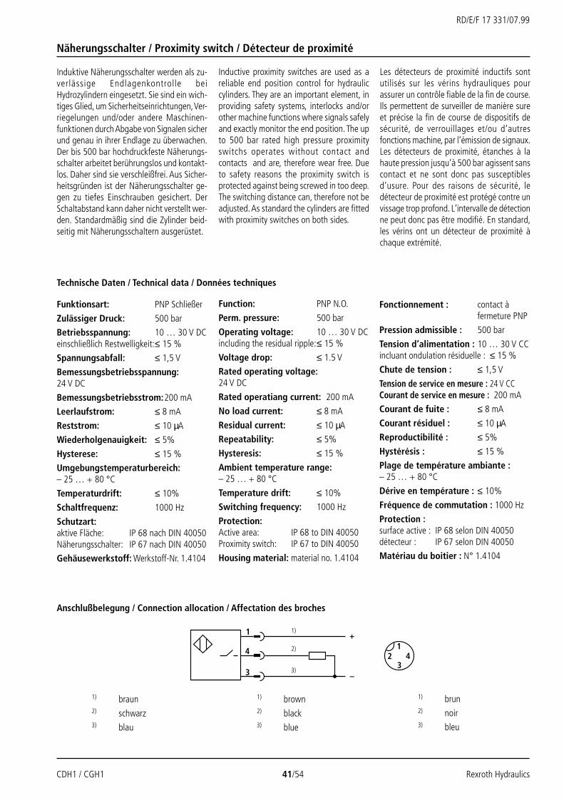
CDH1 / CGH1 41/54 Rexroth Hydraulics
RD/E/F 17 331/07.99
+
–
1
4
3
12
34
Näherungsschalter / Proximity switch / Détecteur de proximité
Induktive Näherungsschalter werden als zu-verlässige Endlagenkontrolle beiHydrozylindern eingesetzt. Sie sind ein wich-tiges Glied, um Sicherheitseinrichtungen, Ver-riegelungen und/oder andere Maschinen-funktionen durch Abgabe von Signalen sicherund genau in ihrer Endlage zu überwachen.Der bis 500 bar hochdruckfeste Näherungs-schalter arbeitet berührungslos und kontakt-los. Daher sind sie verschleißfrei. Aus Sicher-heitsgründen ist der Näherungsschalter ge-gen zu tiefes Einschrauben gesichert. DerSchaltabstand kann daher nicht verstellt wer-den. Standardmäßig sind die Zylinder beid-seitig mit Näherungsschaltern ausgerüstet.
Inductive proximity switches are used as areliable end position control for hydrauliccylinders. They are an important element, inproviding safety systems, interlocks and/orother machine functions where signals safelyand exactly monitor the end position. The upto 500 bar rated high pressure proximityswitchs operates without contact andcontacts and are, therefore wear free. Dueto safety reasons the proximity switch isprotected against being screwed in too deep.The switching distance can, therefore not beadjusted. As standard the cylinders are fittedwith proximity switches on both sides.
Les détecteurs de proximité inductifs sontutilisés sur les vérins hydrauliques pourassurer un contrôle fiable de la fin de course.Ils permettent de surveiller de manière sureet précise la fin de course de dispositifs desécurité, de verrouillages et/ou d‘autresfonctions machine, par l‘émission de signaux.Les détecteurs de proximité, étanches à lahaute pression jusqu‘à 500 bar agissent sanscontact et ne sont donc pas susceptiblesd‘usure. Pour des raisons de sécurité, ledétecteur de proximité est protégé contre unvissage trop profond. L‘intervalle de détectionne peut donc pas être modifié. En standard,les vérins ont un détecteur de proximité àchaque extrémité.
Funktionsart: PNP Schließer
Zulässiger Druck: 500 bar
Betriebsspannung: 10 … 30 V DCeinschließlich Restwelligkeit:≤ 15 %
Spannungsabfall: ≤ 1,5 V
Bemessungsbetriebsspannung:24 V DC
Bemessungsbetriebsstrom:200 mA
Leerlaufstrom: ≤ 8 mA
Reststrom: ≤ 10 µA
Wiederholgenauigkeit: ≤ 5%
Hysterese: ≤ 15 %
Umgebungstemperaturbereich:– 25 … + 80 °C
Temperaturdrift: ≤ 10%
Schaltfrequenz: 1000 Hz
Schutzart:aktive Fläche: IP 68 nach DIN 40050Näherungsschalter: IP 67 nach DIN 40050
Gehäusewerkstoff: Werkstoff-Nr. 1.4104
Function: PNP N.O.
Perm. pressure: 500 bar
Operating voltage: 10 … 30 V DCincluding the residual ripple:≤ 15 %
Voltage drop: ≤ 1.5 V
Rated operating voltage:24 V DC
Rated operatiang current: 200 mA
No load current: ≤ 8 mA
Residual current: ≤ 10 µA
Repeatability: ≤ 5%
Hysteresis: ≤ 15 %
Ambient temperature range:– 25 … + 80 °C
Temperature drift: ≤ 10%
Switching frequency: 1000 Hz
Protection:Active area: IP 68 to DIN 40050Proximity switch: IP 67 to DIN 40050
Housing material: material no. 1.4104
Anschlußbelegung / Connection allocation / Affectation des broches
2)
1)
3)
Fonctionnement : contact àfermeture PNP
Pression admissible : 500 bar
Tension d‘alimentation : 10 … 30 V CCincluant ondulation résiduelle : ≤ 15 %
Chute de tension : ≤ 1,5 V
Tension de service en mesure : 24 V CCCourant de service en mesure : 200 mA
Courant de fuite : ≤ 8 mA
Courant résiduel : ≤ 10 µA
Reproductibilité : ≤ 5%
Hystérésis : ≤ 15 %
Plage de température ambiante :– 25 … + 80 °C
Dérive en température : ≤ 10%
Fréquence de commutation : 1000 Hz
Protection :surface active : IP 68 selon DIN 40050détecteur : IP 67 selon DIN 40050
Matériau du boitier : N° 1.4104
1) braun2) schwarz3) blau
1) brown2) black3) blue
1) brun2) noir3) bleu
Technische Daten / Technical data / Données techniques

Rexroth Hydraulics 42/54 CDH1 / CGH1
RD/E/F 17 331/07.99
X4
L7
X3
PL + X*
1) 1)
L7
X3
PM + X*
1) 1)X5
Näherungsschalter / Proximity switch / Détecteur de proximité
CDH1: AL-Ø 40-320 mm
CGH1: AL-Ø 40-320 mm
Leitungsdose mit 5m KabelMaterial-Nr. 00026512(Leitungsdose ist im Lieferumfang nichtenthalten, muß seperat bestellt werden)
Leitungsdose, abgewinkeltmit 5m Kabel(Lage des Kabelabgangs nicht definier-bar)Material-Nr. 00021404(Leitungsdose ist im Lieferumfang nichtenthalten, muß seperat bestellt werden)
Plug-in connector, angled,with 5m cable(The orientation of the cable exit is notdefinable)Material no. 00021404(Plug-in connector is not included within thescope of supply, has to be ordered separately)
Connecteur femelle coudéavec câble de 5m(L‘emplacement de la sortie du câblene peut pas être déterminé)référence 00021404(Le connecteur femelle n‘est pas inclusdans la fourniture et doit être commandéséparément)
Plug-in connector with 5m cableMaterial no. 00026512(Plug-in connector is not included within thescope of supply, has to be ordered separately)
Connecteur femelle avec câble de 5mréférence 00026512(Le connecteur femelle n‘est pas inclusdans la fourniture et doit être commandéséparément)
Befestigungsarten / Mounting types / Types de fixation

CDH1 / CGH1 43/54 Rexroth Hydraulics
RD/E/F 17 331/07.99
22282836364545565670709090
100100110110125125140140160160180180200200220
Bemerkungen
Hauptmaße siehe Seite 10 und 11
AL = Kolben-Ø
MM = Kolbenstangen-Ø
X* = Hublänge1) = Der Näherungsschalter befindet
sich immer gegenüber desLeitungsanschlusses
2) = Maße auf Anfrage
AL MM PL PM L7 X3 X4 X5Ø Ø
40 112 112 83 94 170 125
50 110 110 92 98 175 130
63 125 125 104 103 180 135
80 138 138 108 108 185 140
100 161 161 129 116 195 150
125 193 193 141 126 205 160
140 209 209 161 146 225 180
160 228 228 191 151 230 185
180 254 254 204 159 235 190
200 264 264 212 166 245 200
220 2) 2) 2) 2) 2) 2)
250 2) 2) 2) 2) 2) 2)
280 2) 2) 2) 2) 2) 2)
320 2) 2) 2) 2) 2) 2)
Notes
For main dimensions see pages 10 and 11
AL = Piston Ø
MM = Piston rod Ø
X* = Stroke length1) = The proximity switch is always
located opposite to the pipeconnection
2) = Dimensions on request
Remarques
Cotes principales : voir pages 10 et 11
AL = Ø de piston
MM = Ø de tige
X* = course1) = le détecteur de proximité se trouve
toujours en face de l‘orificed‘alimentation
2) = cotes sur demande
Näherungsschalter / Proximity switch / Détecteur de proximité
Maße (in mm) / Dimensions (in mm) / Encombrement (en mm)

Rexroth Hydraulics 44/54 CDH1 / CGH1
RD/E/F 17 331/07.99
G1/4
38
Ø 20
M16x2
SW19
Bemerkungen
Für Druckmessung oder Entlüftung.Zum Einbau in den Entlüftungs-/Meßan-schluß. Schraubkupplung mit Rückschlag-ventilfunktion, d.h. sie kann auch unter Druckangeschlossen werden.
Lieferumfang:
Schraubkupplung AB 20-11/K1mit Dichtring aus NBRMaterial-Nr. 00009090
Schraubkupplung AB 20-11/K1 Vmit Dichtring aus FKMMaterial-Nr. 00001264
Notes
For pressure measurement or bleeding.For installation in the bleed/measuring port.Coupling with check valve function, i.e. it canalso be connected when pressure is present.
Scope of supply:
Coupling AB-E 20-11/K1with NBR sealMaterial no. 00009090
Coupling AB-E 20-11/K1 Vwith FKM sealMaterial no. 00001264
Remarques
Pour mesure de la pression ou purge.Pour installation dans l'orifice de purge/demesure. Accouplement fileté avec fonction declapet anti-retour, c.-à.-d. qu‘il peutégalement être monté sous pression.
Fourniture:
Accouplement fileté AB 20-11/K1avec joint NBRréférence 00009090
Accouplement fileté AB 20-11/K1 Vavec joint FKMréférence 00001264
Schraubkupplung / Coupling / Accouplement fileté

CDH1 / CGH1 45/54 Rexroth Hydraulics
RD/E/F 17 331/07.99
1184 7 3 18 5 7 2
61818618
10 12 16
11 14 1717
Ersatzteilbild / Spare parts / Pièces de rechange
CDH1; AL-Ø 40-320 mm
Kolbenstange / Piston rod / Tige Kolben / Piston / Piston
1 Head2 Rear3 Barrel4 Piston rod5 Piston6 Cushioning bush7 Flange
10 Rear MP311 Rear MP512 Round flange MF314 Round flange MF416 Trunnion MT417 Foot MS218 Seal kit:
WiperRod sealPiston sealO-ringGuide bush
1 Tête2 Fond3 Tube4 Tige5 Piston6 Douille d'amortissement7 Bride
10 Fond MP311 Fond MP512 Bride circulaire MF314 Bride circulaire MF416 Tourillon MT417 Pied MS218 Pochette de joints:
Joint racleurJoint de tigeJoint de pistonJoint toriqueBague de guidage
1 Kopf2 Boden3 Rohr4 Kolbenstange5 Kolben6 Dämpfungsbuchse7 Flansch
10 Boden MP311 Boden MP512 Rundflansch MF314 Rundflansch MF416 Schwenkzapfen MT417 Fuß MS218 Dichtsatz:
AbstreiferStangendichtungKolbendichtungO-RingFührungsring
"M"
"A / B"
"T / K / S / C"
"M / T / K / S / C"
"A / B"

Rexroth Hydraulics 46/54 CDH1 / CGH1
RD/E/F 17 331/07.99
1184 3 18 5 2
18188
18
11
15
13 16
Ersatzteilbild / Spare parts / Pièces de rechange
CDH1; AL-Ø 360-500 mm
1 Kopf2 Boden3 Rohr4 Kolbenstange5 Kolben8 Zylinderschraube
11 Boden MP513 Rundflansch ME715 Rundflansch ME816 Schwenkzapfen MT418 Dichtsatz:
AbstreiferStangendichtungKolbendichtungO-RingFührungsring
1 Head2 Rear3 Barrel4 Piston rod5 Piston8 Fillister head screw
11 Rear MP513 Round flange ME715 Round flange ME816 Trunnion MT418 Seal kit:
WiperRod sealPiston sealO-ringGuide bush
1 Tête2 Fond3 Tube4 Tige5 Piston8 Vis à tête cylindrique
11 Fond MP513 Bride circulaire ME715 Bride circulaire ME816 Tourillon MT418 Pochette de joints:
Joint racleurJoint de la tigeJoint de pistonJoint toriqueBague de guidage
Kolbenstange / Piston rod / Tige Kolben / Piston / Piston
"M"
"A"
"T / K / S / C"
"M / T / K / S / C"
"A"

CDH1 / CGH1 47/54 Rexroth Hydraulics
RD/E/F 17 331/07.99
1184 7 3 18 5 7
61818618
181
12 16 1717
Ersatzteilbild / Spare parts / Pièces de rechange
CGH1; AL-Ø 40-320 mm
Kolbenstange / Piston rod / Tige Kolben / Piston / Piston
"M"
"A / B"
"T / K / S / C"
"M / T / K / S / C"
"A / B"
1 Kopf3 Rohr4 Kolbenstange5 Kolben6 Dämpfungsbuchse7 Flansch
12 Rundflansch MF316 Schwenkzapfen MT417 Fuß MS218 Dichtsatz:
AbstreiferStangendichtungKolbendichtungO-RingFührungsring
1 Head3 Barrel4 Piston rod5 Piston6 Cushioning bush7 Flange
12 Round flange MF316 Trunnion MT417 Foot MS218 Seal kit:
WiperRod sealPiston sealO-ringGuide bush
1 Tête3 Tube4 Tige5 Piston6 Douille d'amortissement7 Bride
12 Bride circulaire MF316 Tourillon MT417 Pied MS218 Pochette de joints:
Joint racleurJoint de la tigeJoint de pistonJoint toriqueBague de guidage
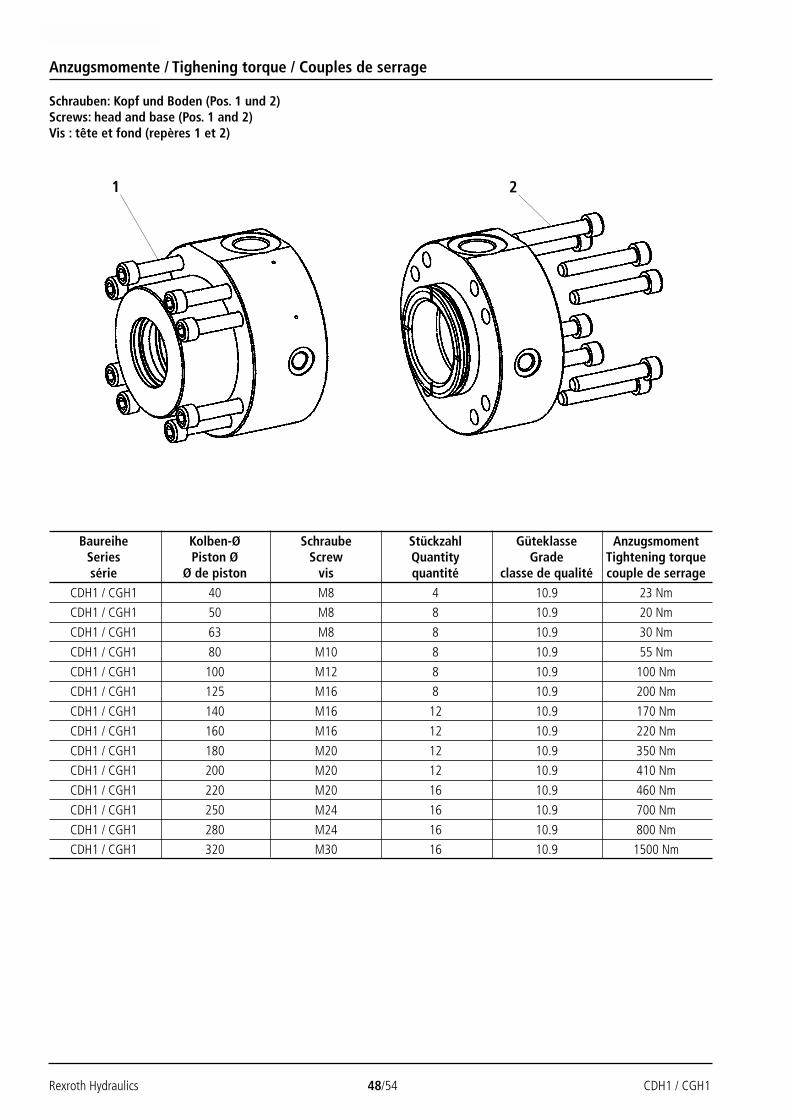
Rexroth Hydraulics 48/54 CDH1 / CGH1
RD/E/F 17 331/07.99
Anzugsmomente / Tighening torque / Couples de serrage
Baureihe Kolben-Ø Schraube Stückzahl Güteklasse AnzugsmomentSeries Piston Ø Screw Quantity Grade Tightening torquesérie Ø de piston vis quantité classe de qualité couple de serrage
CDH1 / CGH1 40 M8 4 10.9 23 Nm
CDH1 / CGH1 50 M8 8 10.9 20 Nm
CDH1 / CGH1 63 M8 8 10.9 30 Nm
CDH1 / CGH1 80 M10 8 10.9 55 Nm
CDH1 / CGH1 100 M12 8 10.9 100 Nm
CDH1 / CGH1 125 M16 8 10.9 200 Nm
CDH1 / CGH1 140 M16 12 10.9 170 Nm
CDH1 / CGH1 160 M16 12 10.9 220 Nm
CDH1 / CGH1 180 M20 12 10.9 350 Nm
CDH1 / CGH1 200 M20 12 10.9 410 Nm
CDH1 / CGH1 220 M20 16 10.9 460 Nm
CDH1 / CGH1 250 M24 16 10.9 700 Nm
CDH1 / CGH1 280 M24 16 10.9 800 Nm
CDH1 / CGH1 320 M30 16 10.9 1500 Nm
Schrauben: Kopf und Boden (Pos. 1 und 2)Screws: head and base (Pos. 1 and 2)Vis : tête et fond (repères 1 et 2)
1 2

CDH1 / CGH1 49/54 Rexroth Hydraulics
RD/E/F 17 331/07.99
Anzugsmomente / Tightening torque / Couples de serrage
Baureihe Kolben-Ø Kolbenstangen-Ø Schraube Stückzahl Güteklasse AnzugsmomentSeries Piston Ø Piston rod Ø Screw Quantity Grade Tightening torquesérie Ø de piston Ø de tige vis quantité classe de qualité couple de serrage
CDH1 / CGH1 160 M10 16 10.9 60 Nm
CDH1 / CGH1 180 M12 16 10.9 80 Nm
CDH1 / CGH1 200 M12 16 10.9 90 Nm
CDH1 / CGH1 220 M12 10.9 90 Nm
CDH1 / CGH1 250 M12 24 10.9 90 Nm
CDH1 / CGH1 280 M12 24 10.9 90 Nm
CDH1 / CGH1 320 10.9
Schrauben: Dichtungsdeckel (Pos. 3)Screws: seal cover (Pos. 3)Vis : couvercle d‘étanchéité (repère 3)
100110110125125140140160160180180200200220
1624
90 Nm230 Nm
2416
M12M16
3

Rexroth Hydraulics 50/54 CDH1 / CGH1
RD/E/F 17 331/07.99
Dichtsätze1) / Seal kits1) / Pochettes de joints1)
Notes
AL = Piston Ø
MM = Piston rod Ø1) = Seal kits for position measuring
system and proximity switch haveseparate material numbers
Remarques
AL = Ø du piston
MM = Ø de la tige1) = Pochettes de joints pour capteur de
position et interrupteur de proximité,référence séparée
Bemerkungen
AL = Kolben-Ø
MM = Kolbenstangen-Ø1) = Dichtsätze für Wegmeßsystem und
Näherungsschalter seperateMaterial-Nr.
CDH1 – Standard / CDH1 – Standard / CDH1 – standard
Material-Nr. / Material no. / référenceAL MM Dichtungsausführung / Seal version / Exécution des joints
Ø Ø M T A K S B C
22 00850072 00849536 00860270 00865855 00861000 00859816 00865886
28 00851087 00858841 00859445 00865856 00861001 00859770 00865887
28 00850181 00857535 00860928 00865857 00861002 00860938 00865888
36 00849392 00860277 00851515 00865859 00861004 00860940 00865890
36 00850191 00860278 00860930 00865860 00861005 00851206 00865891
45 00847956 00847855 00851638 00865862 00861007 00859678 00865893
45 00851086 00860280 00854708 00865863 00861008 00860942 00865894
56 00850905 00856180 00854718 00854668 00861010 00851205 00865896
56 00853936 00860282 00860470 00865865 00861011 00860944 00865897
70 00853382 00860285 00856094 00865867 00861013 00890946 00865899
70 00853966 00860286 00854709 00865868 00861014 00860948 00865900
90 00857949 00856102 00856095 00857647 00861016 00855464 00865902
90 00858281 00860289 00860932 00865870 00861017 00860951 00865903
100 00853965 00860290 00856096 00865871 00849080 00860952 00865904
100 00855683 00860291 00860468 00865872 00861018 00860953 00865905
110 00851146 00857536 00860933 00865873 00861019 00860954 00865906
110 00856497 00852561 00860934 00865874 00861020 00860955 00865907
125 00848603 00860292 00860935 00865875 00861021 00860956 00865908
125 00860294 00860295 00860936 00865876 00861022 00860957 00865909
140 00856431 00860293 00860937 00865877 00861023 00860958 00865910
40
50
63
80
100
125
140
160
180
200

CDH1 / CGH1 51/54 Rexroth Hydraulics
RD/E/F 17 331/07.99
Dichtsätze1) / Seal kits1) / Pochettes de joints1)
CDH1 – Standard + Option F / CDH1 – Standard + Option F / CDH1 – standard + option F
Material-Nr. / Material no. / référence
AL MM Dichtungsausführung / Seal version / Exécution des joints
Ø Ø M+F T+F K+F S+F C+F
22 00861024 00861049 00861074 00861099 00861144
28 00861025 00861050 00861075 00861100 00861145
28 00861026 00861051 00861076 00861101 00861146
36 00861028 00867053 00861078 00861103 00861148
36 00861029 00861054 00861079 00861104 00861149
45 00861031 00861056 00861081 00861106 00861151
45 00861032 00861057 00861082 00861107 00861152
56 00861034 00861059 00861116 00861109 00861140
56 00861035 00861060 00861085 00861112 00861139
70 00861037 00861062 00861087 00861115 00861137
70 00861038 00861063 00861088 00861117 00861136
90 00861040 00861065 00861084 00861122 00861132
90 00861041 00861066 00861090 00861124 00861131
100 00861042 00861067 00861091 00861126 00861129
100 00861043 00861068 00861092 00861128 00861127
110 00861044 00861069 00861093 00861130 00861125
110 00861045 00861070 00861094 00861133 00861123
125 00861046 00861071 00861095 00861135 00861121
125 00861047 00861072 00861096 00861142 00861119
140 00861048 00861073 00861097 00861143 00861118
Notes
AL = Piston Ø
MM = Piston rod Ø1) = Seal kits for position measuring
system and proximity switch haveseparate material numbers
Remarques
AL = Ø du piston
MM = Ø de la tige1) = Pochettes de joints pour capteur de
position et interrupteur de proximité,référence séparée
Bemerkungen
AL = Kolben-Ø
MM = Kolbenstangen-Ø1) = Dichtsätze für Wegmeßsystem und
Näherungsschalter seperateMaterial-Nr.
40
50
63
80
100
125
140
160
180
200

Rexroth Hydraulics 52/54 CDH1 / CGH1
RD/E/F 17 331/07.99
Dichtsätze1) / Seal kits1) / Pochettes de joints1)
Material-Nr. / Material no. / référence
AL MM Dichtungsausführung / Seal version / Exécution des joints
Ø Ø M T A K S B C
22 00867251 00868888 00866746 00868913 00868942 00867132 00868966
28 00867252 00868889 00866747 00868914 00868943 00867133 00868967
28 00867253 00868890 00866748 00868916 00868944 00867134 00868968
36 00864930 00868892 00866750 00868919 00868946 00867136 00868970
36 00867260 00868893 00866751 00868920 00868947 00867137 00868973
45 00867262 00868895 00866753 00868922 00868949 00867139 00868975
45 00867263 00868896 00866754 00868923 00868950 00867140 00868976
56 00867265 00868898 00866756 00868925 00868952 00867142 00868978
56 00867266 00868899 00866757 00868926 00868953 00867143 00868979
70 00867268 00868901 00866759 00868928 00868955 00867146 00868981
70 00867269 00868902 00866760 00868929 00867906 00867147 00868982
90 00867270 00868904 00866762 00868930 00868957 00867149 00868985
90 00867271 00868905 00866763 00868931 00868958 00867150 00868986
100 00867272 00868906 00866764 00868932 00868959 00867151 00868987
100 00867273 00868907 00866765 00868933 00868960 00867152 00868988
110 00867274 00868908 00866766 00868934 00868961 00867153 00868989
110 00867275 00868909 00866767 00868935 00868962 00867154 00868990
125 00867276 00868910 00866768 00868936 00868963 00867155 00868991
125 00867277 00868911 00866769 00868937 00868964 00867156 00868992
140 00867278 00868912 00866770 00868938 00868965 00867157 00868993
Notes
AL = Piston Ø
MM = Piston rod Ø1) = Seal kits for proximity switch have
separate material numbers
Remarques
AL = Ø du piston
MM = Ø de la tige1) = Pochettes de joints pour interrupteur
de proximité, référence séparée
Bemerkungen
AL = Kolben-Ø
MM = Kolbenstangen-Ø1) = Dichtsätze für Näherungsschalter
seperate Material-Nr.
CGH1 – Standard / CGH1 – Standard / CGH1 – standard
40
50
63
80
100
125
140
160
180
200

CDH1 / CGH1 53/54 Rexroth Hydraulics
RD/E/F 17 331/07.99
Dichtsätze1) / Seal kits1) / Pochettes de joints1)
CGH1 – Standard + Option F / CGH1 – Standard + Option F / CGH1 – standard + option F
Material-Nr. / Material no. / référence
AL MM Dichtungsausführung / Seal version / Exécution des joints
Ø Ø M+F T+F K+F S+F C+F
22 00868998 00869025 00869050 00869092 00869117
28 00868999 00869026 00869051 00869093 00869118
28 00869000 00869027 00869052 00869094 00869119
36 00869002 00869029 00869054 00869096 00869121
36 00869003 00869030 00869055 00869097 00869122
45 00869005 00869032 00869057 00869099 00869124
45 00869006 00869033 00869058 00869100 00869125
56 00869008 00869035 00869060 00869102 00869127
56 00869009 00869036 00869061 00869103 00869128
70 00869013 00869038 00869063 00869105 00869130
70 00869014 00869039 00869064 00869106 00869131
90 00869016 00869041 00869066 00869108 00869133
90 00869017 00869042 00869067 00869109 00869134
100 00869018 00869043 00869068 00869110 00869135
100 00869019 00869044 00869070 00869111 00869136
110 00869020 00869045 00869071 00869112 00869137
110 00869021 00869046 00869072 00869113 00869138
125 00869022 00869047 00869073 00869114 00869139
125 00869023 00869048 00869074 00869115 00869140
140 00869024 00869049 00869075 00869116 00869141
Notes
AL = Piston Ø
MM = Piston rod Ø1) = Seal kits for proximity switch have
separate material numbers
Remarques
AL = Ø du piston
MM = Ø de la tige1) = Pochettes de joints pour interrupteur
de proximité, référence séparée
Bemerkungen
AL = Kolben-Ø
MM = Kolbenstangen-Ø1) = Dichtsätze für Näherungsschalter
seperate Material-Nr.
40
50
63
80
100
125
140
160
180
200

Nachdruck verboten – Änderungen vorbehalten 54/54 CDH1 / CGH1Copyrights – Subject to revision / Reproduction interdite – sous réserves de modification
RD/E/F 17 331/07.99
Mannesmann Rexroth AGRexroth Hydraulics
D-97813 Lohr am MainJahnstraße 3-5 • D-97816 Lohr am MainTelefon 0 93 52 / 18-0Telefax 0 93 52 / 18-23 58 • Telex 6 89 418-0eMail [email protected] www.rexroth.com
AB Rexroth MecmanVaruvägen 7, Alvsjö
S-125 81 StockholmTel. (08) 72 79 20 0Fax (08) 86 87 21
Hydraudyne Cylinders B.V.Kruisbroeksestraat 1a
P.O. Box 32 • NL-5280 AA BoxtelTel. (0) 41 16 / 51 95 1Fax (0) 41 16 / 74 12 5 • Telex 5 08 25
Les données contenues dans cette noticeservent exclusivement à la description duproduit oject de la notice et ne sauraient êtreconsidérées comme garantissant, au sensjuridique, les propriétés de ce produit.
The specified data is for product descriptionpurposes only and must not be interpretedas warranted characteristics in a legalsense.
Die angegebenen Daten dienen allein derProduktbeschreibung und sind nicht als zu-gesicherte Eigenschaften im Rechtssinne zuverstehen.
Dichtsätze / Seal kits / Pochettes de joints
Wegemeßsystem / Position measuring system / Système de détection de position
Näherungsschalter / Proximity switch / Détecteur de proximité
Material-Nr. / Material no. / référenceDichtungsausführung / Seal version / Exécution des joints
M / M+F T / T+F A K / K+F S / S+F B C / C+F
00885935 – – 00885937 – –
Material-Nr. / Material no. / référence
Dichtungsausführung / Seal version / Exécution des jointsM / M+F T / T+F A K / K+F S / S+F B C / C+F
00885938 00885939