hydrometry — measurement of liquid flow in open channels...
TRANSCRIPT

Lice
nsed
cop
y: M
r. N
UI U
ser,
Nat
iona
l Uni
vers
ity o
f Ire
land
, Ver
sion
cor
rect
as
of 1
7/05
/201
0 15
:08,
(c)
BS
I
BRITISH STANDARD BS EN ISO 748:2007Hydrometry — Measurement of liquid flow in open channels using current-meters or floats
The European Standard EN ISO 748:2007 has the status of a British Standard
ICS 17.120.20
�������������� ���������������������������������������������������

BS EN ISO 748:2007
Lice
nsed
cop
y: M
r. N
UI U
ser,
Nat
iona
l Uni
vers
ity o
f Ire
land
, Ver
sion
cor
rect
as
of 1
7/05
/201
0 15
:08,
(c)
BS
I
This British Standard was published under the authority of the Standards Policy and Strategy Committee on 30 November 2007
© BSI 2007
ISBN 978 0 580 54670 9
National foreword
This British Standard is the UK implementation of EN ISO 748:2007. It supersedes BS EN ISO 748:2000 which is withdrawn.The UK participation in its preparation was entrusted by Technical Committee CPI/113, Hydrometry, to Subcommittee CPI/113/1, Velocity area methods.A list of organizations represented on this committee can be obtained on request to its secretary.This publication does not purport to include all the necessary provisions of a contract. Users are responsible for its correct application.Compliance with a British Standard cannot confer immunity from legal obligations.
Amendments issued since publication
Amd. No. Date Comments

EUROPEAN STANDARD
NORME EUROPÉENNE
EUROPÄISCHE NORM
EN ISO 748
October 2007
ICS 17.120.20 Supersedes EN ISO 748:2000
English Version
Hydrometry - Measurement of liquid flow in open channels usingcurrent-meters or floats (ISO 748:2007)
Hydrométrie - Mesurage du débit des liquides dans lescanaux découverts au moyen de débitmètres ou de
flotteurs (ISO 748:2007)
Hydrometrie - Durchflussmessung in offenen Gerinnenmittels Fließgeschwindigkeitsmessgeräten oder
Schwimmern (ISO 748:2007)
This European Standard was approved by CEN on 21 September 2007.
CEN members are bound to comply with the CEN/CENELEC Internal Regulations which stipulate the conditions for giving this EuropeanStandard the status of a national standard without any alteration. Up-to-date lists and bibliographical references concerning such nationalstandards may be obtained on application to the CEN Management Centre or to any CEN member.
This European Standard exists in three official versions (English, French, German). A version in any other language made by translationunder the responsibility of a CEN member into its own language and notified to the CEN Management Centre has the same status as theofficial versions.
CEN members are the national standards bodies of Austria, Belgium, Bulgaria, Cyprus, Czech Republic, Denmark, Estonia, Finland,France, Germany, Greece, Hungary, Iceland, Ireland, Italy, Latvia, Lithuania, Luxembourg, Malta, Netherlands, Norway, Poland, Portugal,Romania, Slovakia, Slovenia, Spain, Sweden, Switzerland and United Kingdom.
EUROPEAN COMMITTEE FOR STANDARDIZATIONC OM ITÉ EUR OP ÉEN DE NOR M ALIS AT IONEUROPÄISCHES KOMITEE FÜR NORMUNG
Management Centre: rue de Stassart, 36 B-1050 Brussels
© 2007 CEN All rights of exploitation in any form and by any means reservedworldwide for CEN national Members.
Ref. No. EN ISO 748:2007: E
Lice
nsed
cop
y: M
r. N
UI U
ser,
Nat
iona
l Uni
vers
ity o
f Ire
land
, Ver
sion
cor
rect
as
of 1
7/05
/201
0 15
:08,
(c)
BS
I

Foreword
This document (EN ISO 748:2007) has been prepared by Technical Committee ISO/TC 113 "Hydrometric determinations" in collaboration with Technical Committee CEN/TC 318 “Hydrometry” the secretariat of which is held by BSI.
This European Standard shall be given the status of a national standard, either by publication of an identical text or by endorsement, at the latest by April 2008, and conflicting national standards shall be withdrawn at the latest by April 2008.
This document supersedes EN ISO 748:2000.
According to the CEN/CENELEC Internal Regulations, the national standards organizations of the following countries are bound to implement this European Standard: Austria, Belgium, Bulgaria, Cyprus, Czech Republic, Denmark, Estonia, Finland, France, Germany, Greece, Hungary, Iceland, Ireland, Italy, Latvia, Lithuania, Luxembourg, Malta, Netherlands, Norway, Poland, Portugal, Romania, Slovakia, Slovenia, Spain, Sweden, Switzerland and the United Kingdom.
Endorsement notice
The text of ISO 748:2007 has been approved by CEN as a EN ISO 748:2007 without any modification.
EN ISO 748:2007
Lice
nsed
cop
y: M
r. N
UI U
ser,
Nat
iona
l Uni
vers
ity o
f Ire
land
, Ver
sion
cor
rect
as
of 1
7/05
/201
0 15
:08,
(c)
BS
I

Reference numberISO 748:2007(E)
INTERNATIONAL STANDARD
ISO748
Fourth edition2007-10-15
Hydrometry — Measurement of liquid flow in open channels using current-meters or floats
Hydrométrie — Mesurage du débit des liquides dans les canaux découverts au moyen de débitmètres ou de flotteurs
EN ISO 748:2007
Lice
nsed
cop
y: M
r. N
UI U
ser,
Nat
iona
l Uni
vers
ity o
f Ire
land
, Ver
sion
cor
rect
as
of 1
7/05
/201
0 15
:08,
(c)
BS
I
ii
Lice
nsed
cop
y: M
r. N
UI U
ser,
Nat
iona
l Uni
vers
ity o
f Ire
land
, Ver
sion
cor
rect
as
of 1
7/05
/201
0 15
:08,
(c)
BS
I
iii
Contents Page
Foreword............................................................................................................................................................. v 1 Scope ..................................................................................................................................................... 1 2 Normative references ........................................................................................................................... 1 3 Terms and definitions........................................................................................................................... 1 4 Principle of the methods of measurements....................................................................................... 1 5 Selection and demarcation of site ...................................................................................................... 2 5.1 Selection of site .................................................................................................................................... 2 5.2 Demarcation of site............................................................................................................................... 3 6 Measurement of cross-sectional area ................................................................................................ 3 6.1 General................................................................................................................................................... 3 6.2 Measurement of width.......................................................................................................................... 3 6.3 Measurement of depth.......................................................................................................................... 4 7 Measurement of velocity...................................................................................................................... 5 7.1 Measurement of velocity using current-meters................................................................................. 5 7.1.1 Rotating-element current-meters ........................................................................................................ 5 7.1.2 Electromagnetic current-meters ......................................................................................................... 5 7.1.3 Measurement procedure ...................................................................................................................... 5 7.1.4 Oblique flow .......................................................................................................................................... 6 7.1.5 Determination of the mean velocity in a vertical ............................................................................... 7 7.1.6 Errors and limitations......................................................................................................................... 10 7.2 Measurement of velocity using floats............................................................................................... 11 7.2.1 General................................................................................................................................................. 11 7.2.2 Selection of site .................................................................................................................................. 11 7.2.3 Measuring procedure ......................................................................................................................... 11 7.2.4 Types of float....................................................................................................................................... 11 7.2.5 Determination of velocity................................................................................................................... 12 7.2.6 Main sources of error ......................................................................................................................... 13 8 Computation of discharge ................................................................................................................. 13 8.1 General................................................................................................................................................. 13 8.2 Graphical method ............................................................................................................................... 13 8.2.1 Depth-velocity-integration ................................................................................................................. 13 8.2.2 Velocity-area integration method (velocity-contour method) ........................................................ 14 8.3 Arithmetic methods ............................................................................................................................ 16 8.3.1 Mean-section method......................................................................................................................... 16 8.3.2 Mid-section method............................................................................................................................ 16 8.4 Independent vertical method............................................................................................................. 17 8.5 Mean-section method — Horizontal planes ..................................................................................... 20 8.6 Determination of discharge from surface-float velocity measurements ...................................... 20 8.7 Determination of discharge for variations of water level ............................................................... 22 8.7.1 General................................................................................................................................................. 22 8.7.2 Computation of discharge ................................................................................................................. 22 8.7.3 Computation of mean water level ..................................................................................................... 22 9 Uncertainties in flow measurement .................................................................................................. 23 9.1 General................................................................................................................................................. 23 9.2 Definition of uncertainty..................................................................................................................... 23 9.3 Method of calculating the uncertainty in discharge by measurement of velocity by
current-meter....................................................................................................................................... 24 9.3.1 General................................................................................................................................................. 24
EN ISO 748:2007
Lice
nsed
cop
y: M
r. N
UI U
ser,
Nat
iona
l Uni
vers
ity o
f Ire
land
, Ver
sion
cor
rect
as
of 1
7/05
/201
0 15
:08,
(c)
BS
I

iv
9.3.2 Contributory uncertainties ................................................................................................................. 24 9.3.3 Example................................................................................................................................................ 26 9.3.4 Combined uncertainty ........................................................................................................................ 26 9.4 Method of calculating the uncertainty in discharge by measurement of velocity using
floats..................................................................................................................................................... 27 9.4.1 General ................................................................................................................................................. 27 9.4.2 Contributory uncertainties ................................................................................................................. 27 9.4.3 Combined uncertainty in discharge.................................................................................................. 28 9.4.4 Example................................................................................................................................................ 28 Annex A (informative) Correction for sag, pull, slope and temperature in measurement of cross-
section width by tape or wire............................................................................................................. 30 Annex B (informative) Distance measurement across the cross-section .................................................. 33 Annex C (informative) Corrections for wetted length of wire when measuring depths with wire not
normal to surface ................................................................................................................................ 36 Annex D (informative) Correction for drift ..................................................................................................... 39 Annex E (informative) Uncertainties in the velocity-area measurement..................................................... 40 Annex F (informative) Determination of mean velocity from float measurements .................................... 44 Bibliography ..................................................................................................................................................... 46
EN ISO 748:2007
Lice
nsed
cop
y: M
r. N
UI U
ser,
Nat
iona
l Uni
vers
ity o
f Ire
land
, Ver
sion
cor
rect
as
of 1
7/05
/201
0 15
:08,
(c)
BS
I

v
Foreword
ISO (the International Organization for Standardization) is a worldwide federation of national standards bodies (ISO member bodies). The work of preparing International Standards is normally carried out through ISO technical committees. Each member body interested in a subject for which a technical committee has been established has the right to be represented on that committee. International organizations, governmental and non-governmental, in liaison with ISO, also take part in the work. ISO collaborates closely with the International Electrotechnical Commission (IEC) on all matters of electrotechnical standardization.
International Standards are drafted in accordance with the rules given in the ISO/IEC Directives, Part 2.
The main task of technical committees is to prepare International Standards. Draft International Standards adopted by the technical committees are circulated to the member bodies for voting. Publication as an International Standard requires approval by at least 75 % of the member bodies casting a vote.
Attention is drawn to the possibility that some of the elements of this document may be the subject of patent rights. ISO shall not be held responsible for identifying any or all such patent rights.
ISO 748 was prepared by Technical Committee ISO/TC 113, Hydrometry, Subcommittee SC 1, Velocity area methods.
This fourth edition cancels and replaces the third edition (ISO 748:1997), which has been technically revised.
EN ISO 748:2007
Lice
nsed
cop
y: M
r. N
UI U
ser,
Nat
iona
l Uni
vers
ity o
f Ire
land
, Ver
sion
cor
rect
as
of 1
7/05
/201
0 15
:08,
(c)
BS
I

blank
Lice
nsed
cop
y: M
r. N
UI U
ser,
Nat
iona
l Uni
vers
ity o
f Ire
land
, Ver
sion
cor
rect
as
of 1
7/05
/201
0 15
:08,
(c)
BS
I

1
Hydrometry — Measurement of liquid flow in open channels using current-meters or floats
1 Scope
This International Standard specifies methods for determining the velocity and cross-sectional area of water flowing in open channels without ice cover, and for computing the discharge therefrom.
It covers methods of employing current-meters or floats to measure the velocities. It should be noted that although, in some cases, these measurements are intended to determine the stage-discharge relation of a gauging station, this International Standard deals only with single measurements of the discharge; the continuous recording of discharges over a period of time is covered in ISO 1100-1 and ISO 1100-2.
NOTE The methods for determining the velocity and cross-sectional area of water flowing in open channels with ice cover are specified in ISO 9196.
2 Normative references
The following referenced documents are indispensable for the application of this document. For dated references, only the edition cited applies. For undated references, the latest edition of the referenced document (including any amendments) applies.
ISO 772, Hydrometric determinations — Vocabulary and symbols
ISO 1088, Hydrometry — Velocity-area methods using current-meters — Collection and processing of data for determination of uncertainties in flow measurement
ISO 2537, Hydrometry — Rotating-element current-meters
ISO 3455, Hydrometry — Calibration of current-meters in straight open tanks
ISO/TS 15768, Measurement of liquid velocity in open channels — Design, selection and use of electromagnetic current meters
3 Terms and definitions
For the purposes of this document, the terms and definitions given in ISO 772 apply.
4 Principle of the methods of measurements
4.1 The principle of these methods consists of determining velocity and cross-sectional area. A measuring site is chosen conforming to the specified requirements (see Clause 5); the width, depending on its magnitude, is measured either by means of steel tape or by some other surveying method, and the depth is measured at a number of points (known as verticals) across the width, sufficient to determine the shape and area of the cross-section (see Clause 6).
EN ISO 748:2007
Lice
nsed
cop
y: M
r. N
UI U
ser,
Nat
iona
l Uni
vers
ity o
f Ire
land
, Ver
sion
cor
rect
as
of 1
7/05
/201
0 15
:08,
(c)
BS
I

2
Velocity observations using current-meters are made at each vertical preferably at the same time as measurement of depth, especially in the case of unstable beds (see 7.1.5).
Velocity observations can also be made using surface floats or velocity-rods (see 7.2).
4.2 The discharge is computed either arithmetically or graphically by summing the products of the velocity and corresponding area for a series of observations in a cross-section. If unit width discharge is required, it is generally computed from the individual observations at each measurement vertical.
5 Selection and demarcation of site
5.1 Selection of site
The site selected should comply as far as possible with the following requirements.
a) The channel at the measuring site should be straight and of uniform cross-section and slope in order to minimize abnormal velocity distribution. When the length of the channel is restricted, it is recommended for current-meter measurements that the straight length upstream should be at least twice that downstream.
b) Flow directions for all points on any vertical across the width should be parallel to one another and at right angles to the measurement section.
c) The bed and margins of the channels should be stable and well defined at all stages of flow in order to facilitate accurate measurement of the cross-section and ensure uniformity of conditions during and between discharge measurements.
d) The curves of the distribution of velocities should be regular in the vertical and horizontal planes of measurement.
e) Conditions at the section and in its vicinity should also be such as to preclude changes taking place in the velocity distribution during the period of measurement.
f) Sites displaying vortices, reverse flow or dead water should be avoided.
g) The measurement section should be clearly visible across its width and unobstructed by trees, aquatic growth or other obstacles.
h) Measurement of flow from bridges can be a convenient and sometimes safer way of sampling width, depth and velocity. When gauging from a bridge with divide piers, each section of the channel should be measured separately. Particular care should be taken in determining the velocity distribution when bridge apertures are surcharged or obstructed.
i) The depth of water at the section should be sufficient at all stages to provide for the effective immersion of the current-meter or float, whichever is to be used.
j) If the site is to be established as a permanent station, it should be easily accessible at all times with all necessary measurement equipment.
k) The section should be sited away from pumps, sluices and outfalls, if their operation during a measurement is likely to create unsteady flow conditions.
l) Sites where there is converging or diverging flow should be avoided.
m) In those instances where it is necessary to make measurements in the vicinity of a bridge, it is preferable that the measuring site be upstream of the bridge. However, in certain cases and where accumulation of ice, logs or debris is liable to occur, it is acceptable that the measuring site be downstream of the bridge.
EN ISO 748:2007
Lice
nsed
cop
y: M
r. N
UI U
ser,
Nat
iona
l Uni
vers
ity o
f Ire
land
, Ver
sion
cor
rect
as
of 1
7/05
/201
0 15
:08,
(c)
BS
I

3
n) The measurement of flow under ice cover is dealt with in ISO 9196. For streams subject to formation of ice cover, the requirements of measurement specified in this International Standard can be used during the free water season.
o) It may, under certain conditions of river flow or level, prove necessary to carry out current-meter measurements on sections other than the original chosen location. This is quite acceptable if there are no substantial unmeasured losses or gains to the river in the intervening reach and so long as all flow measurements can be related to any stage value recorded at the principal reference section.
5.2 Demarcation of site
5.2.1 If the site is to be established as a permanent station or likely to be used frequently for future measurement, it should be provided with means for demarcation of the cross-section and for determination of stage. Where the site is used only once, or infrequently, and there are no means of determining stage values on site, care should be taken to ensure that the water level and/or flow do not change significantly during the measurement period.
5.2.2 The position of each cross-section, normal to the mean direction of flow, shall be defined on the two banks by clearly visible and readily identifiable markers. Where a site is subject to considerable snow cover, the section line-markers may be referenced to other objects such as rock cairns.
5.2.3 The stage shall be read from a gauge at intervals throughout the period of measurement and the gauge datum shall be related by precise levelling to a standard datum.
5.2.4 An auxiliary gauge on the opposite bank shall be installed where there is likelihood of a difference in the level of water surface between the two banks. This is particularly important in the case of very wide rivers. The mean of the measurements taken from the two gauges shall be used as the mean level of the water surface and as a base for the cross-sectional profile of the stream.
6 Measurement of cross-sectional area
6.1 General
The cross-sectional profile of the open channel at the gauging-site shall be determined at a sufficient number of points to establish the shape of the bed.
The location of each point is determined by measuring its horizontal distance to a fixed reference point on one bank of the channel, in line with the cross-section. This in turn allows calculation of the area of individual segments separated by successive verticals where velocities are measured.
6.2 Measurement of width
6.2.1 Measurement of the width of the channel and the width of the individual segments may be obtained by measuring the horizontal distance from or to a fixed reference point which shall be in the same plane as the cross-section at the measuring site.
6.2.2 Where the width of the channel permits, these horizontal distances shall be measured by direct means, for example a graduated tape or suitable marked wire, care being taken to apply the necessary corrections given in Annex A. The intervals between the verticals, i.e. the widths of the segments, shall be similarly measured.
6.2.3 Where the channel is too wide for the above methods of measurement, and a boat is used, the horizontal distance may be determined by optical or electronic distance-meters, by the use of a differential Global Positioning System, or by one of the surveying methods given in Annex B.
EN ISO 748:2007
Lice
nsed
cop
y: M
r. N
UI U
ser,
Nat
iona
l Uni
vers
ity o
f Ire
land
, Ver
sion
cor
rect
as
of 1
7/05
/201
0 15
:08,
(c)
BS
I
4
6.3 Measurement of depth
6.3.1 Measurement of depth shall be made at intervals close enough to define the cross-sectional profile accurately. The number of points at which depth shall be measured should be the same as the number of points at which velocity is measured (see 7.1.3).
6.3.2 The depth shall be measured by employing either sounding-rods or sounding-lines or other suitable devices. Where the channel is of sufficient depth, an echo-sounder may be used. If the velocity is high and the channel is sufficiently deep, it is preferable to use an echo-sounder or other device which will not require large corrections. Difficulty may be experienced when attempting to measure depth at times of high velocity. Annex C of this document offers alternative methods.
6.3.3 When a sounding-rod or sounding-line is used, it is desirable that at least two readings be taken at each point and the mean value adopted for calculations, unless the difference between the two values is more than 5 %, in which case two further readings shall be taken. If these are within 5 %, they shall be accepted for the measurement and the two earlier readings discarded. If they are again different by more than 5 %, no further readings shall be taken but the average of all four readings shall be adopted for the measurement, noting that the accuracy of this measurement is reduced.
When an echo-sounder is used, the average of several readings shall always be taken at each point. Regular calibrations of the instrument shall be carried out under the same conditions of salinity and temperature as those of the water to be measured.
Where it is impracticable to take more than one reading of the depth, the uncertainty in measurement may be increased (see Clause 9).
6.3.4 Where measurements of the depths are made separately from the velocity measurements and the water level is not steady, the water level shall be observed at the time of each measurement of the depth. When this is not possible, the water level shall be observed at sufficient intervals for the value of the level at the time of each determination of depth to be obtained by interpolation.
6.3.5 When, during the determination of discharge, the bed profile changes appreciably, depth measurements should be carried out by taking one depth reading at each point at the beginning and one at the end of the velocity measurement at each vertical, and the mean value of these two measurements shall be taken as the effective depth. Care should be exercised when taking repeated soundings to avoid disturbance of the bed.
6.3.6 Inaccuracies in soundings are most likely to occur owing to:
a) the departure from the vertical of the sounding rod or line, particularly in deep water, when the velocity is high;
b) the penetration of the bed by the sounding weight or rod;
c) the nature of the bed when an echo-sounder is used.
Errors due to a) may be minimized by the use, where practicable, of an echo-sounder, or pressure-measuring device. The effect of drag on a sounding line may be reduced by using a streamlined lead weight at the end of a fine wire. A correction shall be applied to the wetted length of wire if the wire is not normal to the water-surface. It is recommended that the angle of departure from the vertical of the sounding line should not be greater than 30° in view of the inaccuracies involved. Two alternative methods of applying the correction are given in Annex C.
Errors due to b) may be reduced by fitting a base plate to the lower end of the sounding-rod, or by fastening a disk to the end of the sounding line, provided they will not cause additional scour of fine bed material due to high velocities.
Errors due to c) may be reduced by selecting an echo-sounder frequency that most adequately depicts the bed-water interface.
EN ISO 748:2007
Lice
nsed
cop
y: M
r. N
UI U
ser,
Nat
iona
l Uni
vers
ity o
f Ire
land
, Ver
sion
cor
rect
as
of 1
7/05
/201
0 15
:08,
(c)
BS
I
5
6.3.7 In certain cases, for example floods, it may be impossible to determine an adequate profile of cross-section during the measurement. For those cases, the full profile shall be determined by surveying methods, either before or after the measurement. However, it should be recognized that this method is subject to errors due to possible erosion or deposition in the cross-section between the time the profile is determined and the time of discharge measurement.
7 Measurement of velocity
7.1 Measurement of velocity using current-meters
7.1.1 Rotating-element current-meters
Rotating-element current-meters shall be manufactured, calibrated and maintained according to ISO 2537 and ISO 3455. They should be used only within their calibrated range and fitted on suspension equipment similar to that used during calibration.
In the vicinity of the minimum speed of response, the uncertainty in determining the velocity is high. Care should be exercised when measuring velocities near the minimum speed of response.
For high velocities, the propeller, in the case of propeller-type current-meters, or the reduction ratio where available, shall be chosen in order that the maximum speed of rotation can be correctly measured by the revolution counter.
No rotating-element current-meter shall be selected for use where the depth at the point of measurement is less than four times the diameter of the impeller that is to be used, or of the body of the meter itself, whichever is the greater. No part of the meter shall break the surface of the water. An exception to this is the case where the cross-section is very shallow at one side but is the best available.
7.1.2 Electromagnetic current-meters
Electromagnetic current-meters are acceptable for making measurements of point velocity. These current-meters have the advantage that they have no moving parts and thereby eliminate uncertainty due to friction and resistance. They should be calibrated throughout the range of velocity for which they are to be used, and should meet accuracy requirements similar to rotating-element current-meters. They should not be used outside the range of calibration. Electromagnetic current-meters may be capable of operation in shallower depths than rotating element current-meters and of detecting and measuring flow reversal.
No electromagnetic current-meter should be selected for use where the depth at the point of measurement is less than three times the vertical dimension of the probe (see ISO/TS 15768). An exception to this is the case where the cross-section is very shallow at one side but is the best available.
7.1.3 Measurement procedure
Velocity observations are normally made at the same time as measurements of the depth. This method shall be particularly used in the case of unstable beds. Where, however, the two measurements are made at different times, the velocity observations shall be taken at a sufficient number of places, and the horizontal distance between observations shall be measured as described in 6.2.2 and 6.2.3.
In judging the specific number n of verticals in small channels (< 5 m) that are to be defined for the purpose of determining flow at a particular location, the following criteria shall be applied. These criteria shall be the minimum requirement and only practical constraints of time, costs, or on site conditions should result in a reduction of these numbers.
⎯ Channel width < 0,5 m n = 5 to 6
⎯ Channel width > 0,5 m and < 1 m n = 6 to 7
EN ISO 748:2007
Lice
nsed
cop
y: M
r. N
UI U
ser,
Nat
iona
l Uni
vers
ity o
f Ire
land
, Ver
sion
cor
rect
as
of 1
7/05
/201
0 15
:08,
(c)
BS
I
6
⎯ Channel width > 1 m and < 3 m n = 7 to 12
⎯ Channel width > 3 m and < 5 m n = 13 to 16
⎯ Channel width > 5 m n W 22
For channel widths > 5 m, the number of verticals shall be chosen so that the discharge in each segment is less than 5 % of the total, insofar as possible, and that in no case should exceed 10 %.
In all instances, measurements of depth made at the water's edge are additional to the above. The first and last verticals should be as close as practically possible to the water’s edge.
It is further recommended that the location of the verticals be selected after a previous cross-section survey.
The current-meter shall be held in the desired position in each vertical by means of a wading-rod in the case of shallow channels, or by suspending it from a cable or rod in the case of deeper channels. The current-meter shall be held so that it is not affected by any disturbances of flow.
Current-meter counters or velocity indicators with a digital display of low resolution should not be used at low velocities, e.g. less than 0,15 m/s.
When the orientation of the current-meter can be controlled, e.g. when wading gauging with rods, the meter should be held at right angles to the measuring cross-section. Where oblique flow occurs, or the cross-section is not at right angles to the direction of flow (see 7.1.4) and the meter is suspended, it will align itself with the direction of flow. In such cases, the meter shall be allowed to adjust to the flow before readings are started.
Care should be taken to ensure that the current-meter observations are not affected by random surface-waves and wind.
When a number of points in a vertical are to be measured, a number of current-meters fixed to the same rod or cable can be used to measure corresponding velocities simultaneously whilst ensuring that there is no mutual interference.
If there is any appreciable deflection of the cable on which the meter is suspended, a correction shall be applied for the depth of the measuring-point. No generally applicable correction factor can be given, but it shall be determined by the user for the particular instrument and conditions of measurement (see Annex C).
NOTE The selection and use of appropriate suspension equipment is described in ISO 3454 and ISO 4375.
The velocity at each selected point shall be observed by exposing the current-meter for a minimum of 30 s.
Where the velocity is subject to periodic pulsations in excess of 30 s, the exposure time should be increased accordingly (see ISO 1088).
The current-meter shall be removed from the water or brought to the surface at intervals for visual examination, usually when passing from one vertical to another.
A spin test, where appropriate, should be performed before and after each discharge measurement to ensure that the mechanism of the current-meter operates freely (see ISO 2537).
In channels where the flow is unsteady, it is possible to correct for the variations in the total discharge during the period of the measurement not only by observing the change in stage, but also by continuously measuring the velocity at some conveniently chosen point in the main current.
7.1.4 Oblique flow
If oblique flow is unavoidable, the angle of the direction of the flow to the perpendicular to the cross-section shall be measured and the measured velocity adjusted. Special instruments have been developed for measuring the angle and velocity at a point simultaneously. Where, however, these are not available and
EN ISO 748:2007
Lice
nsed
cop
y: M
r. N
UI U
ser,
Nat
iona
l Uni
vers
ity o
f Ire
land
, Ver
sion
cor
rect
as
of 1
7/05
/201
0 15
:08,
(c)
BS
I

7
there is insignificant wind, the angle of flow throughout the vertical can be assumed to be the same as that observed on the surface. This angle can be measured with appropriate equipment provided that the operator is located above the measurement vertical. If the channel is very deep or if the local bed profile is changing rapidly, this assumption shall not be accepted without confirmation.
If the measured angle between the flow direction and the perpendicular to the cross-section is θ the velocity used for the computation of flow discharge shall be:
corrected measured cosθv v= (1)
NOTE Some current-meters are equipped to measure the normal component of velocity directly when held perpendicular to the measurement cross-section in oblique flow. This correction would not be applied in such cases.
7.1.5 Determination of the mean velocity in a vertical
7.1.5.1 Choice and classification
The choice of the method for determining velocity depends on certain factors. These are: time available, width and depth of the channel, bed conditions in the measuring section and the upstream reach, rate of variation of level, degree of accuracy desired and equipment used.
These methods are classified as follows:
a) velocity distribution method (see 7.1.5.2);
b) reduced point methods (see 7.1.5.3);
c) integration method (see 7.1.5.4).
7.1.5.2 Velocity distribution method
Using this method, the values of the velocity are obtained from observations at a number of points in each vertical between the surface of the water and the bed of the channel. The number and spacing of the points should be so chosen as to define accurately the velocity distribution in each vertical with a difference in readings between two adjacent points of not more than 20 % with respect to the higher value. The location of the top and the bottom readings should be chosen, taking into account the specification under 7.1.1 and 7.1.2 (see also ISO 1088).
The velocity observations at each position are then plotted graphically and the unit width discharge or mean velocity determined by planimeter, digitizer or equivalent method. The mean velocity in the vertical may also be obtained by dividing the unit width discharge by the total depth.
NOTE 1 This method may not be suitable for routine discharge measurements because the apparent gain in precision may be offset by errors resulting from change of stage during the long period of time needed for making the measurement.
NOTE 2 Although this clause deals primarily with the determination of mean velocity in the vertical, it may be necessary to apply the same principle to the determination of mean velocity close to the vertical side or wall of a channel. The velocity curve can be extrapolated from the last measuring point to the bed or vertical side of the channel by calculating vx from Equation (2):
1m
x axv va
⎛ ⎞= ⎜ ⎟
⎝ ⎠ (2)
where
vx is the open point velocity in the extrapolated zone at a distance x from the bed or vertical side;
va is the velocity at the last measuring point at a distance a from the bed or vertical side;
m is an exponent.
EN ISO 748:2007
Lice
nsed
cop
y: M
r. N
UI U
ser,
Nat
iona
l Uni
vers
ity o
f Ire
land
, Ver
sion
cor
rect
as
of 1
7/05
/201
0 15
:08,
(c)
BS
I

8
The mean velocity, v , between the bottom (or a vertical side) of the channel and the nearest point of measurement (where the measured velocity is va) can be calculated directly from Equation (3):
1 amv v
m⎛ ⎞
= ⎜ ⎟+⎝ ⎠ (3)
Generally, m lies between 5 and 7 but it may vary over a wider range depending on the hydraulic resistance. The value m = 4 applies to coarse beds or vertical sides while m = 10 is characteristic of smooth beds or vertical sides.
m is obtained as follows:
ver
ver
20,3
gCmg g C
⎛ ⎞⎜ ⎟= +⎜ ⎟+⎝ ⎠
(4)
where
g is the acceleration due to gravity (m/s2);
Cver is Chezy's coefficient on a vertical (m0,5/s).
NOTE 3 An alternative method of obtaining the velocity in the region below the last measuring-point is based on the assumption that the velocity for some distance up from the bed of the channel is proportional to the logarithm of the distance X from that boundary. If the observed velocities at points approaching the bed are plotted against log X, then the best-fitting straight line through these points can be extended to the boundary. The velocities close to the boundary can then be read from the graph.
7.1.5.3 Reduced point methods
7.1.5.3.1 General
These methods, less strict than methods exploring the entire field of velocity, are used frequently because they require less time than the velocity-distribution method (7.1.5.2). They are based, however, on theoretical velocity profiles.
It is recommended that for a new gauging section the accuracy of the selected method be assessed by comparing the results of preliminary gaugings with those obtained from the velocity distribution method.
7.1.5.3.2 One-point method
Velocity observations shall be made on each vertical by exposing the current-meter at 0,6 of the depth below the surface. The value observed shall be taken as the mean velocity in the vertical.
7.1.5.3.3 Two-point method
Velocity observations shall be made on each vertical by exposing the current-meter at 0,2 and 0,8 of the depth below the surface. The average of the two values shall be taken as the mean velocity in the vertical.
7.1.5.3.4 Three-point method
Velocity observations shall be made on each vertical by exposing the current-meter at 0,2, 0,6 and 0,8 of the depth below the surface. The 0,6 measurement may be weighted and the mean velocity v obtained from Equation (5):
( )0,2 0,6 0,80,25 2v v v v= + + (5)
EN ISO 748:2007
Lice
nsed
cop
y: M
r. N
UI U
ser,
Nat
iona
l Uni
vers
ity o
f Ire
land
, Ver
sion
cor
rect
as
of 1
7/05
/201
0 15
:08,
(c)
BS
I

9
7.1.5.3.5 Five-point method
Velocity measurements are made by exposing the current-meter on each vertical at 0,2, 0,6 and 0,8 of the depth below the surface and as near as possible to the surface and the bed. The mean velocity v may be determined from a graphical plot of the velocity profile with a planimeter, or from Equation (6).
( )surface 0,2 0,6 0,8 bed0,1 3 3 2v v v v v v= + + + + (6)
7.1.5.3.6 Six-point method
Velocity observations are made by exposing the current-meter on each vertical at 0,2, 0,4, 0,6 and 0,8 of the depth below the surface and as near as possible to the surface and the bed (see 7.1.5.3.7.2). The velocity observations at each point are plotted in graphical form and the mean velocity or unit width discharge determined with the aid of a planimeter. Alternatively, the mean velocity v may be found algebraically from Equation (7).
( )surface 0,2 0,4 0,6 0,8 bed0,1 2 2 2 2v v v v v v v= + + + + + (7)
7.1.5.3.7 Surface one-point method
7.1.5.3.7.1 In flashy or other conditions where the above methods are not feasible, velocity shall be measured at one point just below the surface. The depth of submergence of the current-meter shall be uniform over all the verticals; care shall be taken to ensure that the current-meter observations are not affected by random surface-waves and wind. This 'surface' velocity may be converted to the mean velocity in the vertical by multiplying it by a predetermined coefficient specific to the section and to the discharge.
The coefficient shall be computed for all stages by correlating the velocity at the surface with the velocity at 0,6 of the depth or, where greater accuracy is desired, with the mean velocity obtained by one of the other methods previously described.
It may be noted for guidance that in general, the coefficient varies between 0,84 and 0,90 depending upon the shape of the velocity profile; the higher values between 0,88 and 0,90 are usually obtained when the bed is smooth.
7.1.5.3.7.2 The use of current-meters near to the surface, or to the bed of the channel, shall be in accordance with the manufacturer's instructions (see also 7.1.1 and 7.1.2).
7.1.5.3.8 Alternate sampling methods
Alternative sampling methods for determining the mean velocity in the vertical may be utilized under exceptional circumstances, e.g. high velocity, rapidly changing stage or floating debris provided the method applied can be demonstrated by experiment to give results of similar accuracy to those listed above.
7.1.5.4 Integration method
In this method, the current-meter is lowered and raised through the entire depth on each vertical at a uniform rate. The speed at which the meter is lowered or raised should not be more than 5 % of the mean water velocity and should not in any event exceed 0,04 m/s. Two complete cycles should be made on each vertical and if the results differ by more than 10 %, the operation (two complete cycles) should be repeated until results within this limit are obtained.
The integration method gives good results if the time of measurement allowed is sufficiently long (60 s to 100 s). The technique can be, but is not normally, used in depths of less than 1 m.
With a propeller-type current-meter, the average velocity can then be read from the instrument calibration as equivalent to the average number of revolutions (being derived as the total number of revolutions divided by the total time taken for the measurement in that vertical). Uncertainties introduced by using meters with more than one calibration equation should be avoided.
EN ISO 748:2007
Lice
nsed
cop
y: M
r. N
UI U
ser,
Nat
iona
l Uni
vers
ity o
f Ire
land
, Ver
sion
cor
rect
as
of 1
7/05
/201
0 15
:08,
(c)
BS
I

10
By using a current-meter that measures velocity directly, such as the electromagnetic current-meter, the mean velocity in the vertical can be obtained by direct reading of the instrument.
When a sounding rod or weight is used, it will not be possible to measure the velocity throughout the entire vertical; a zone may, for example, remain unmeasured near the channel bed. An estimate of the unit width discharge of this zone can be obtained from:
m fu
23
v hq = (8)
where
qu is the unit width discharge below the measured zone;
vm is the mean velocity for the measured part of the vertical;
hf is the depth of the unmeasured zone.
Similarly, the unit width discharge for any unmeasured zone near the surface is obtained from:
m ss 0,9
v hq = (9)
where
qs is the unit width discharge above the measured zone;
vm is the mean velocity for the measured part of the vertical;
hs is the depth of the unmeasured zone.
As far as possible, the type of measuring equipment should be selected to minimize the depth of the unmeasured zones.
7.1.6 Errors and limitations
Estimates of the possible errors that may occur when using the various methods detailed in 7.1.5 are given in 9.3.3. It should be noted that these estimates are of possible random errors which may occur even when all the precautions noted earlier and below are observed. If the measurement is not made under these best conditions, additional uncertainty should be included when estimating the overall uncertainty of the measurement.
Errors may arise:
a) if the flow is unsteady;
b) if material in suspension interferes with the performance of the current-meter;
c) if skew flow occurs, and the appropriate correction factors are not known accurately;
d) if the current-meter is used for measurement of velocity outside the range established by the calibration;
e) if the set-up for measurement (such as rods or cables suspending the current-meter, the boat, etc.) is different from that used during the calibration of the current-meter, in which case a systematic error may be introduced;
f) if there is significant disturbance of the water surface by wind;
EN ISO 748:2007
Lice
nsed
cop
y: M
r. N
UI U
ser,
Nat
iona
l Uni
vers
ity o
f Ire
land
, Ver
sion
cor
rect
as
of 1
7/05
/201
0 15
:08,
(c)
BS
I

11
g) if the current-meter is not held steadily in the correct place during the measurement, which is the case when gauging from a boat which is drifting (see Annex D), or when an oscillating transverse movement occurs. In the latter case, the resultant of the flow velocity and the transverse velocities gives rise to serious positive errors.
7.2 Measurement of velocity using floats
7.2.1 General
This method shall only be used when it is impossible to employ a current-meter because of access difficulties, excessive velocities and depths, the presence of material in suspension, where velocities are too low for current-meter measurement or in cases of reconnaissance.
7.2.2 Selection of site
Three cross-sections shall be selected along the reach of the channel as described in Clause 5, at the beginning, midway and at the end of the reach. The cross-sections shall be far enough apart for the time which the floats take to pass from one cross-section to the next to be measured accurately. The midway cross-section shall be used only for the purpose of checking the velocity measurement between the cross-sections at the beginning and at the end of the reach. A minimum duration of float movement of 20 s is recommended.
7.2.3 Measuring procedure
The float shall be released far enough above the upper cross-section to attain a constant velocity before reaching the first cross-section. The time at which the float passes each of the three cross-sections is then noted. This procedure shall be repeated with the floats at various distances from the bank of the river. The distances of the float from the bank as it passes each cross-section may be determined by suitable optical means, for example, a theodolite.
It is also possible to use the double stopwatch method described in Annex F. This allows the determination of the velocity of the float and the position of its path in the section in a single operation and without the need for special or surveying equipment.
Increasing the number of floats used to determine the velocity in each segment will improve the accuracy of the measurement.
The width of the channel shall be divided into a certain number of segments of equal width. If, however, the channel is very irregular, each segment shall have approximately the same discharge. The number of segments shall not be less than three, but where possible a minimum of five shall be used, the actual number of segments depending on the time available for these observations at the particular stage of the river.
7.2.4 Types of float
7.2.4.1 General
The velocity of the water in each segment can be determined by
a) surface floats,
b) double floats,
c) other types of floats.
NOTE Separately flowing blocks of ice, provided they are small, can be used as surface floats during ice drifting.
The coefficients for obtaining the mean velocity from the measurements for the various types of floats are given in 7.2.5.
EN ISO 748:2007
Lice
nsed
cop
y: M
r. N
UI U
ser,
Nat
iona
l Uni
vers
ity o
f Ire
land
, Ver
sion
cor
rect
as
of 1
7/05
/201
0 15
:08,
(c)
BS
I
12
7.2.4.2 Surface floats
These may be used during floods when velocity measurements are to be made quickly. They shall not be used when their movement is likely to be affected by winds.
7.2.4.3 Double floats
These may be used for measurements of velocities in deep rivers. The sub-surface body may be positioned at 0,6 of the depth below the surface, or at other depths to obtain direct velocity measurements at these depths.
7.2.4.4 Other types of floats
Other methods of obtaining the mean velocity in each segment may be used if the bed profile is regular over the measuring reach:
a) Sub-surface floats
These may be used for measurement of velocities in very deep rivers. The length of the sub-surface float, sometimes called the multiple float, which consists of separate elements suitably attached together to permit flexibility and supported by a surface float, shall be approximately equal to the water depth, but the float shall in no case touch the bottom.
b) Velocity-rods
These may be used for measurement of velocities in the case of artificial or other regular channels where the cross-section is uniform, the bed is free from weeds, and the depth of the water is constant. The velocity-rod (sometimes called a float-rod) shall be at least 0,95 of the depth of the channel but shall not touch the bottom.
7.2.5 Determination of velocity
7.2.5.1 Method
The float velocity shall be determined by dividing the distance between the cross-sections by the time taken by the float to travel this distance. Several measurements of the float velocities shall be taken and the mean of these measurements shall be multiplied by the appropriate coefficient to obtain the mean velocity in the segment. The coefficient derived from current-meter measurements at the site at a stage as near as possible to that during the float measurement may be used for converting the float velocity to mean velocity.
7.2.5.2 Surface floats
Where it is not possible to check the coefficient directly, it may be assumed for guidance that, in general, the coefficient of the surface float varies between 0,84 and 0,90 depending upon the shape of the velocity profile. The higher values are usually obtained when the bed is smooth, but values outside this range may occur under certain circumstances.
7.2.5.3 Double floats
Where it is not possible to check the coefficient directly, it may be accepted for guidance that when the sub-surface body is situated at 0,6 of the depth, the coefficient is approximately equal to 1,0 and at 0,5 of the depth, the coefficient is approximately equal to 0,96.
7.2.5.4 Other types of floats
Where a direct check on the coefficient is not possible, it may be assumed that the coefficient of the sub-surface floats and velocity-rods varies in general over the range 0,8 to 1,0.
EN ISO 748:2007
Lice
nsed
cop
y: M
r. N
UI U
ser,
Nat
iona
l Uni
vers
ity o
f Ire
land
, Ver
sion
cor
rect
as
of 1
7/05
/201
0 15
:08,
(c)
BS
I

13
7.2.6 Main sources of error
Errors may occur during the measurement of discharge by floats and the main sources are listed below. They shall be taken into consideration when estimating the overall error as given in Clause 9.
Errors may arise:
a) if the coefficient from which the mean velocity is obtained from the float velocity is not known accurately;
b) if too few segments are used for the velocity distribution;
c) if a sub-surface float or velocity-rod is used and the depth of the channel is not uniform throughout the measuring reach;
d) if the float does not travel in the centre of the panel due to oblique currents;
e) if there is wind, but it should be noted that this error is generally negligible in comparison with others listed above, unless a surface float is used.
8 Computation of discharge
8.1 General
The method of determination of the mean velocity or unit width discharge in each vertical has been dealt with in 7.1 and 7.2. In these subclauses, the method of determination of discharge from current-meter measurements and float measurements is presented. These methods have been classed as the graphical method (8.2) and the arithmetic method (8.3), the latter being particularly useful for computations carried out in the field. The methods given in 8.4 to 8.7 are applicable for special circumstances.
8.2 Graphical method
8.2.1 Depth-velocity-integration
The velocity readings recorded for each vertical are plotted against depth as shown in Figure 1. The area contained by the velocity curve produced for each vertical gives the discharge for unit width of the corresponding section. Where necessary, velocity curves can be extrapolated to the surface and bed using the methods described in notes at the end of 7.1.5.2. The values of unit-width discharges v ⋅d are then plotted on the upper part of the diagram and joined to form a continuous curve. The area enclosed between this curve and the line representing the water surface gives the total discharge through the section.
In the case of velocity measurements by the integration or reduced point methods, the unit-width discharge at each vertical is obtained directly as the product of the mean velocity v and the corresponding depth d.
When velocity measurements are not carried out on the same verticals on which the depth measurements are made, the v curve shall be plotted across the width of the stream and the value of v corresponding to the verticals where depth measurements are made shall be taken for plotting the v ⋅d curve.
EN ISO 748:2007
Lice
nsed
cop
y: M
r. N
UI U
ser,
Nat
iona
l Uni
vers
ity o
f Ire
land
, Ver
sion
cor
rect
as
of 1
7/05
/201
0 15
:08,
(c)
BS
I

14
Key X distance (m) Y1 mean velocity (m/s) Y2 depth (m) Y3 unit width discharge (m2/s)
Figure 1 — Computation of discharge from current-meter measurements — Depth-velocity integration method
i iQ v d B∆= ∑ (10)
where
Q is the total discharge;
v is the average velocity in segment;
di is the depth of segment;
∆B is the incremental width.
8.2.2 Velocity-area integration method (velocity-contour method)
Based on the velocity-distribution curves of the verticals, a velocity-distribution diagram for the cross-section [see Figure 2 a)] shall be prepared showing lines of equal velocity. Starting from the maximum, the areas enclosed by the successive equal-velocity curves and the water surface shall be measured by a planimeter and shall be plotted in another diagram [as shown in Figure 2 b)] with the ordinate indicating the velocity and the abscissa indicating the corresponding area enclosed by the respective velocity curve. The area enclosed by the velocity-area curve represents the discharge of the cross-section.
EN ISO 748:2007
Lice
nsed
cop
y: M
r. N
UI U
ser,
Nat
iona
l Uni
vers
ity o
f Ire
land
, Ver
sion
cor
rect
as
of 1
7/05
/201
0 15
:08,
(c)
BS
I

15
Key X distance (m) Y1 surface velocity (m/s) Y2 depth (m)
1 surface velocity distribution curve 2 maximum velocity 3 lines of equal velocity (m/s)
a) Velocity contours in a section
Key X area (m2) Y velocity (m/s)
1 maximum velocity 2 mean velocity, ,v (m/s)
,Q v A= ∆∑
b) Total flow
Figure 2 — Computation of discharge from current-meter measurements — Velocity-area integration method
EN ISO 748:2007
Lice
nsed
cop
y: M
r. N
UI U
ser,
Nat
iona
l Uni
vers
ity o
f Ire
land
, Ver
sion
cor
rect
as
of 1
7/05
/201
0 15
:08,
(c)
BS
I
16
8.3 Arithmetic methods
8.3.1 Mean-section method
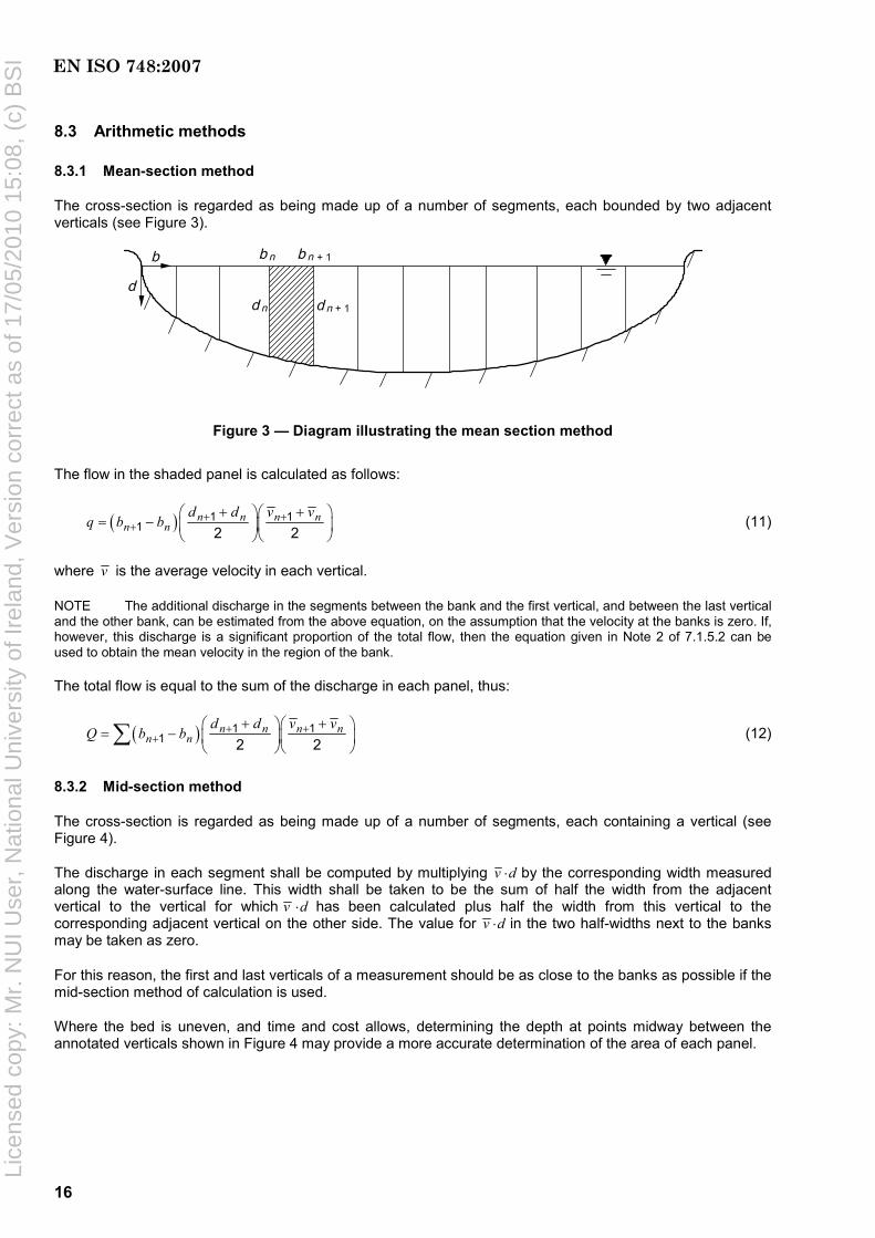
The cross-section is regarded as being made up of a number of segments, each bounded by two adjacent verticals (see Figure 3).
Figure 3 — Diagram illustrating the mean section method
The flow in the shaded panel is calculated as follows:
( ) 1 11 2 2
n n n nn n
d d v vq b b + +
++ +⎛ ⎞⎛ ⎞
= − ⎜ ⎟⎜ ⎟⎝ ⎠⎝ ⎠
(11)
where v is the average velocity in each vertical.
NOTE The additional discharge in the segments between the bank and the first vertical, and between the last vertical and the other bank, can be estimated from the above equation, on the assumption that the velocity at the banks is zero. If, however, this discharge is a significant proportion of the total flow, then the equation given in Note 2 of 7.1.5.2 can be used to obtain the mean velocity in the region of the bank.
The total flow is equal to the sum of the discharge in each panel, thus:
( ) 1 11 2 2
n n n nn n
d d v vQ b b + +
++ +⎛ ⎞⎛ ⎞
= − ⎜ ⎟⎜ ⎟⎝ ⎠⎝ ⎠
∑ (12)
8.3.2 Mid-section method
The cross-section is regarded as being made up of a number of segments, each containing a vertical (see Figure 4).
The discharge in each segment shall be computed by multiplying v ⋅d by the corresponding width measured along the water-surface line. This width shall be taken to be the sum of half the width from the adjacent vertical to the vertical for which v ⋅d has been calculated plus half the width from this vertical to the corresponding adjacent vertical on the other side. The value for v ⋅d in the two half-widths next to the banks may be taken as zero.
For this reason, the first and last verticals of a measurement should be as close to the banks as possible if the mid-section method of calculation is used.
Where the bed is uneven, and time and cost allows, determining the depth at points midway between the annotated verticals shown in Figure 4 may provide a more accurate determination of the area of each panel.
EN ISO 748:2007
Lice
nsed
cop
y: M
r. N
UI U
ser,
Nat
iona
l Uni
vers
ity o
f Ire
land
, Ver
sion
cor
rect
as
of 1
7/05
/201
0 15
:08,
(c)
BS
I

17
Figure 4 — Diagram illustrating the mid-section method
For this method, the flow in each panel is calculated as shown below:
1 12
n nn n
b bq v d + −−⎛ ⎞= ⎜ ⎟
⎝ ⎠ (13)
where again v is the average velocity in the vertical.
The computation is carried out at each vertical and the total discharge through the section is obtained by summing these partial discharges as follows:
1 12
n nn n
b bQ v d + −−⎛ ⎞= ⎜ ⎟
⎝ ⎠∑ (14)
8.4 Independent vertical method
This method is useful for measuring streams with rapidly changing discharge. Several verticals are chosen and their distances measured from a fixed reference point [Figure 5 a)]. On each gauging, measurements of velocity and depth at all the chosen verticals are made, using one of the methods described above. The water level is measured at the beginning and end of the series of measurements on each vertical. For each segment, a separate stage discharge relation is prepared. Subsequently, the discharge of the river at a given stage can be determined by combining the discharges for each segment.
By employing this gauging technique over a period of time and if a sufficiently large range in flow has been covered, it will be possible to derive a relationship between stage and unit-width discharge for each vertical. A family of curves can then be constructed, each curve representing an independent stage/discharge relationship for the corresponding segment of channel width [Figure 5 b)]. This assumes that the channel geometry remains constant and that no change occurs in the position of a vertical relative to the reference point.
Then, for a given value of stage, total flow in the cross-section is obtained by using a mathematical method by summation of all segment discharges [Figure 5 c)]; or with a graphical method [Figure 5 d)] by plotting the unit-width discharge for all verticals and determining the area under this curve.
Total flow in the cross-section for any given value of stage can be obtained by either of these methods.
EN ISO 748:2007
Lice
nsed
cop
y: M
r. N
UI U
ser,
Nat
iona
l Uni
vers
ity o
f Ire
land
, Ver
sion
cor
rect
as
of 1
7/05
/201
0 15
:08,
(c)
BS
I

18
Key X channel width (m) Y stage (m)
1 verticals 2 channel bed 3 stage datum
a) Verticals in cross-section
Key X discharge per unit (m3/s) Y stage (m)
b) Stage/discharge curves for individual verticals
Figure 5 — Computation of discharge from current-meter measurement — Independent vertical method (continued)
EN ISO 748:2007
Lice
nsed
cop
y: M
r. N
UI U
ser,
Nat
iona
l Uni
vers
ity o
f Ire
land
, Ver
sion
cor
rect
as
of 1
7/05
/201
0 15
:08,
(c)
BS
I

19
Key X total discharge (m3/s) Y stage (m)
c) Total discharge (mathematical method)
Key X distance (m) Y discharge per unit width (m3/s)
A distribution of q for h1 or h2
d) Graphical method
Figure 5 — Computation of discharge from current-meter measurement — Independent vertical method
EN ISO 748:2007
Lice
nsed
cop
y: M
r. N
UI U
ser,
Nat
iona
l Uni
vers
ity o
f Ire
land
, Ver
sion
cor
rect
as
of 1
7/05
/201
0 15
:08,
(c)
BS
I

20
8.5 Mean-section method — Horizontal planes
Instead of determining the mean velocity in each vertical, the mean velocities for a number of horizontal planes can be determined by a corresponding procedure to that given in 7.1.5.2. A similar method to that given in 8.3.1 can then be used to determine the discharge. The use of horizontal and vertical-plane computation is particularly suited to measurements in regular-shaped channels, as it enables a check to be made on the accuracy of the computation.
8.6 Determination of discharge from surface-float velocity measurements
If the upstream and downstream cross-sections are plotted as shown in Figure 6 a) and then divided into a suitable number of segments of equal width, the cross-sectional area of each of these segments can be determined. Halfway between the two cross-section lines, another line MN shall be drawn parallel to the cross-sectional lines. The starting and ending points of each float may then be plotted and joined by firm lines, while the surface-points separating the various panels of the two cross-sections may be joined by dotted lines. Where the firm lines cross the line MN, the corresponding mean velocity (float velocity multiplied by the appropriate coefficient - see Note 1 below) shall be plotted normal to MN and the end points of these velocity vectors joined to form a velocity-distribution curve [Figure 6 b)].
Key 1 surface velocity distribution 2 depth (m) 3 direction of flow
a) Measurement sections and float paths
Figure 6 — Computation of discharge from float measurements (continued)
EN ISO 748:2007
Lice
nsed
cop
y: M
r. N
UI U
ser,
Nat
iona
l Uni
vers
ity o
f Ire
land
, Ver
sion
cor
rect
as
of 1
7/05
/201
0 15
:08,
(c)
BS
I

21
Key 1 velocity (m/s)
b) Mean velocity-distribution curve from float measurements
Figure 6 — Computation of discharge from float measurements
The mean area of corresponding segments of the upper and lower cross-sections, when multiplied by the mean velocity for this panel as shown by the velocity-distribution curve, represents the discharge through that segment. The summation of the discharges for all the segments is equal to the total discharge. The mean velocity in a panel may be determined by measuring, by means of a planimeter, the area under the velocity-distribution curve for the corresponding segment or, alternatively, an approximate value may be adopted equal to the reading of the velocity halfway across the panel.
2
mi i
iA A
Q v′+
= ∑ (15)
where
iv is the mean velocity in the segment;
iA is the area of upstream segment;
iA′ is the area of downstream segment.
NOTE 1 When it is impossible to obtain satisfactory movement of the floats across the whole width of the river, for instance if the floats move towards the centreline of the flow, an unadjusted discharge can be determined by measuring the mean of the surface velocities. This discharge has then to be multiplied by a coefficient determined from the results of current-meter measurements carried out simultaneously with float measurements at the level which approximates to that of the float measurements.
NOTE 2 Annex F presents a method for determining the discharge from a float measurement using two stop watches (see 7.2.3).
EN ISO 748:2007
Lice
nsed
cop
y: M
r. N
UI U
ser,
Nat
iona
l Uni
vers
ity o
f Ire
land
, Ver
sion
cor
rect
as
of 1
7/05
/201
0 15
:08,
(c)
BS
I

22
8.7 Determination of discharge for variations of water level
8.7.1 General
If the fluctuation of water level during the period of velocity measurement is less than 5 % of the mean depth or 0,05 m, whichever is the lesser dimension, the mean value shall be adopted for the computation of the discharge. If the fluctuation is more than this amount, then the discharge shall be computed as shown in 8.7.2 and the mean water level corresponding to this discharge computed as shown in 8.7.3.
8.7.2 Computation of discharge
The water level is plotted separately for each segment to form a series of steps as shown in Figure 7. Alternatively, the levels can be joined by a smooth curve. A curve of mean velocity multiplied by depth is then plotted above the water-surface line, the area enclosed representing the total discharge.
8.7.3 Computation of mean water level
The mean water level representative of the discharge measurement shall be computed from the equations:
i iq zz
Q= ∑ (16)
i i i iq b d v= (17)
where
z is the weighted mean water level above the gauge datum;
iq is the partial discharge in the ith segment;
iz is the mean water level corresponding to the partial discharge ;iq
Q is the total discharge and equal to the sum of the partial discharges ;iq∑
ib is the width of the ith segment;
id is the depth of the ith segment;
iv is the mean velocity in the ith segment.
The required measurements are illustrated in Figure 7.
EN ISO 748:2007
Lice
nsed
cop
y: M
r. N
UI U
ser,
Nat
iona
l Uni
vers
ity o
f Ire
land
, Ver
sion
cor
rect
as
of 1
7/05
/201
0 15
:08,
(c)
BS
I

23
Key 1 weighted mean water level above the gauge datum 2 gauge datum
Figure 7 — Computation of discharge and mean water level for variations of water level
9 Uncertainties in flow measurement
9.1 General
The uncertainty in a single measurement of discharge is dealt with in ISO 5168, to which reference should be made. Additional information is given in the GUM:19951), especially Clauses 2 and 3. In these clauses, a general outline of the method of estimating this uncertainty under conditions of steady flow is given. In Annex E, the individual components of the uncertainty are examined and examples of these are given. It should not be assumed, however, that these are generally applicable and it should be stressed that the observations on which they are based did not include all kinds and sizes of rivers (see ISO 1088).
9.2 Definition of uncertainty
All measurements of a physical quantity are subject to uncertainties. These may be due to systematic errors (biases) in the equipment used for calibration and measurement, or to random scatter caused by, for example, a lack of sensitivity of the equipment used for the measurement. The result of a measurement thus is only an estimate of the true value of the measured quantity and therefore is complete only when accompanied by a statement of its uncertainty.
The discrepancy between the true and measured values is the measurement error. The measurement error, which cannot be known, causes an uncertainty about the correctness of the measurement result. The uncertainty is expressed quantitatively as a “parameter … that characterizes the dispersion of the values that could reasonably be attributed to the measurand” (GUM:1995, 2.2.3). The GUM further states that the parameter may be, for example, a standard deviation or the half-length of an interval having a stated level of confidence, and that all sources of uncertainty, including those arising from systematic effects, contribute to the dispersion.
1) To be republished as ISO/IEC Guide 98-3.
EN ISO 748:2007
Lice
nsed
cop
y: M
r. N
UI U
ser,
Nat
iona
l Uni
vers
ity o
f Ire
land
, Ver
sion
cor
rect
as
of 1
7/05
/201
0 15
:08,
(c)
BS
I

24
The measurement error is a combination of component errors that arise during the performance of various elementary operations during the measurement process. For measurements of composite quantities that depend on several component quantities, the total error of the measurement is a combination of the errors in all component quantities. Determination of measurement uncertainty involves identification and characterization of all components of error, quantification of the corresponding uncertainties, and combination of the component uncertainties. The uncertainties are combined using the statistical rules for combining standard deviations, giving proper consideration to correlations among all of the various sources of measurement error in order to account for both systematic and random errors. The resulting uncertainty values are termed standard uncertainties; they correspond to one standard deviation of the probability distribution of measurement errors.
In some applications it is necessary to express the uncertainty of a measurement as a band or interval that may be expected to contain a specified fraction of the distribution of values that could reasonably be attributed to the measurand. Such an interval is obtained by multiplying the standard uncertainty by a factor, k, usually in the range 2 to 3, called the coverage factor. The fraction of the distribution contained by the interval is called the level of confidence. The relation between the level of confidence and the coverage factor depends on the probability distribution of measurement errors.
In this clause, uncertainties are given as standard uncertainties (one standard deviation) and are expressed as percentages of the measured values (relative or percentage uncertainties). (Note that the use of standard uncertainties is a change from previous editions of this International Standard, which used expanded uncertainties with a coverage factor of 2.) If expanded uncertainties are required, the standard normal (Gaussian) distribution is used to determine the coverage factor corresponding to a specified degree of confidence. In particular, expanded uncertainties with a coverage factor of 2 have an approximate level of confidence of 95 %. The expanded uncertainty with a coverage factor of 1 has an approximate level of confidence of 68 %.
9.3 Method of calculating the uncertainty in discharge by measurement of velocity by current-meter
9.3.1 General
The measurement method, briefly, consists of dividing the channel cross-section under consideration into segments by m verticals and measuring the width, depth and mean velocity (denoted by bi, di and vi, respectively) associated with each vertical i. The mean velocity vi at each vertical is computed from point velocity measurements made at each of several depths on the vertical. The flow is computed as follows:
i i iQ F b d v= ∑ (18)
where
Q is the flow (in cubic metres per second);
F is a factor, assumed to be unity, that relates the discrete sum over the finite number of verticals to the integral of the continuous function over the cross-section.
9.3.2 Contributory uncertainties
The relative (percentage) combined standard uncertainty in the measurement is given by Equation (19):
( )( ) ( )
( )
2 2 2 2b, d, ,
2 2 2 1m s 2
1
m
i i i i i v ii
m
i i ii
b d v u u u
u Q u u
b d v
=
=
+ +
= + +⎛ ⎞⎜ ⎟⎜ ⎟⎝ ⎠
∑
∑ (19)
EN ISO 748:2007
Lice
nsed
cop
y: M
r. N
UI U
ser,
Nat
iona
l Uni
vers
ity o
f Ire
land
, Ver
sion
cor
rect
as
of 1
7/05
/201
0 15
:08,
(c)
BS
I

25
where
u (Q) is the relative (percentage) combined standard uncertainty in discharge;
b, d, ,, ,i i v iu u u are the relative (percentage) standard uncertainties in the width, depth and mean velocity measured at vertical i;
us is the uncertainty due to variable responsiveness of the current-meter (ucm), width measurement instrument (ubm) and depth sounding instrument (uds).
2 2 2s cm bm dsu u u u= + + (20)
An estimated practical value of 1 % may be taken for this expression.
um is the uncertainty due to the limited number of verticals, and
m is the number of verticals.
The mean velocity iv at vertical i is an estimate of the average of point measurements of velocity made at one or more depths in the vertical (see for example 7.1.5.3). The uncertainty in iv is computed as follows:
( ) ( )2 2 2 2p, c, e,
1i i i i
iu v u u u
n⎛ ⎞
= + +⎜ ⎟⎝ ⎠
(21)
where
2p,iu is the uncertainty in mean velocity iv due to the limited number of depths at which velocity
measurements are made at vertical i;
ni is the number of depths in the vertical i at which velocity measurements are made;
uc,i is the uncertainty in the velocity at a particular measuring point in vertical i due to lack of repeatability of the current-meter;
ue,i is the uncertainty in point velocity at a particular depth in vertical i due to velocity fluctuations (pulsations) in the stream during the exposure time of the current-meter.
Combining Equations (19) and (21) yields:
( )( ) ( )
( )
2 2 2 2 2 2b, d, p, c, e,
2 2 2 1m s 2
1
1m
i i i i i i i iii
m
i i ii
b d v u u u u un
u Q u u
b d v
=
=
⎛ ⎞⎛ ⎞+ + +⎜ ⎟⎜ ⎟⎜ ⎟⎝ ⎠⎝ ⎠= + +
⎛ ⎞⎜ ⎟⎜ ⎟⎝ ⎠
∑
∑ (22)
If the measurement verticals are placed so that the segment discharges (bi di vi) are approximately equal and if the component uncertainties are equal from vertical to vertical, then Equation (22) simplifies to:
( ) ( )12
2 2 2 2 2 2 2m s b d p c e
1 1u Q u u u u u u um n
⎡ ⎤⎛ ⎞⎛ ⎞ ⎛ ⎞= + + + + + +⎢ ⎥⎜ ⎟⎜ ⎟ ⎜ ⎟⎝ ⎠ ⎝ ⎠⎢ ⎥⎝ ⎠⎣ ⎦
(23)
EN ISO 748:2007
Lice
nsed
cop
y: M
r. N
UI U
ser,
Nat
iona
l Uni
vers
ity o
f Ire
land
, Ver
sion
cor
rect
as
of 1
7/05
/201
0 15
:08,
(c)
BS
I

26
9.3.3 Example
It is required to estimate the uncertainty in a current-meter gauging from the following particulars:
Number of verticals used in the gauging 20
Number of points taken in the vertical (0,2 and 0,8) 2
Average velocity in measuring section above 0,3 m/s
Exposure time of current-meter 3 min
Rating of current-meter individual rating
Component uncertainties (percentages) can be obtained from information given in Annex E, which presents the results of investigations carried out since the publication of the first edition of this International Standard in 1968.
um 2,5 (Table E.6)
us 1,0 (see above)
ub 0,5 (see E.2 line 1)
ud 0,5 (see E.3 line 2)
up 3,5 (Table E.4)
uc 1,0 (Table E.5)
ue 3,0 (at 0,2 depth) (Table E.3)
3,0 (at 0,8 depth) (Table E.3)
Therefore
2 2e 3 3 4,2u = + =
9.3.4 Combined uncertainty
Therefore, from Equation (23):
( ) ( ) ( )( )( )122 2 2 2 2 2 2
m s b d p c e1 1u Q u u u u u u um n⎡ ⎤= + + + + + +⎢ ⎥⎣ ⎦
( ) ( ) ( )( )( )122 2 2 2 2 2 21 12,5 1,0 0,5 0,5 3,5 1,0 4,220 2u Q ⎡ ⎤= + + + + + +⎢ ⎥⎣ ⎦
giving
u (Q) = 2,89 %
EN ISO 748:2007
Lice
nsed
cop
y: M
r. N
UI U
ser,
Nat
iona
l Uni
vers
ity o
f Ire
land
, Ver
sion
cor
rect
as
of 1
7/05
/201
0 15
:08,
(c)
BS
I

27
The expanded uncertainty at the 95 % confidence level, U95, is obtained by applying a coverage factor of k = 2,
Thus:
U95(Q) = k* u(Q)
= 2 × 2,89
= 5,78 %
Therefore
U95(Q) = 6 %
Now, if the measured flow is Q m3/s, the result of the measurement is expressed as:
Q m3/s ± 6 % (expanded uncertainty, coverage factor k = 2, approximate level of confidence = 95 %).
9.4 Method of calculating the uncertainty in discharge by measurement of velocity using floats
9.4.1 General
Whilst there have been considerable investigations carried out into the uncertainties in current-meter gauging, little work has been performed into the uncertainties in float gauging. As a result, there is little guidance in the literature and little research reported to allow reliable recommendations to be made. The following analysis is therefore given as a guide until more information is available.
9.4.2 Contributory uncertainties
The equation for discharge is: (see 7.2 and 8.6)
f 2i i
iA A
Q F K v′ +⎛ ⎞
= ⎜ ⎟⎝ ⎠
∑ (24)
where
Q is the discharge (cubic metres per second);
F is a factor, assumed to be unity, that relates the discrete sum over the finite number of verticals to the integral of the continuous function over the cross-section;
Kf is the coefficient of velocity for the float;
iv is the mean float velocity in the ith segment;
Ai and iA′ are the ith segment areas of upstream and downstream cross-sections, respectively.
The overall uncertainty in discharge is composed of
a) uncertainties in width: ub,i in estimating cross-section areas,
b) uncertainties in depth: ud,i in estimating cross-section areas (allowing for scour and fill if any),
EN ISO 748:2007
Lice
nsed
cop
y: M
r. N
UI U
ser,
Nat
iona
l Uni
vers
ity o
f Ire
land
, Ver
sion
cor
rect
as
of 1
7/05
/201
0 15
:08,
(c)
BS
I
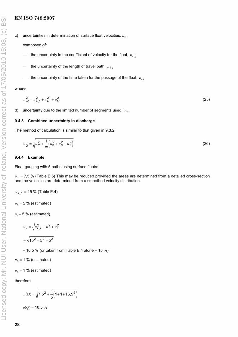
28
c) uncertainties in determination of surface float velocities: uv,i
composed of:
⎯ the uncertainty in the coefficient of velocity for the float, ,k fu
⎯ the uncertainty of the length of travel path, ,L iu
⎯ the uncertainty of the time taken for the passage of the float, ,t iu
where
2 2 2 2, , , ,v i k f L i t iu u u u= + + (25)
d) uncertainty due to the limited number of segments used, um.
9.4.3 Combined uncertainty in discharge
The method of calculation is similar to that given in 9.3.2.
( )2 2 2 2m b d
1Q vu u u u u
m= + + + (26)
9.4.4 Example
Float gauging with 5 paths using surface floats:
um = 7,5 % (Table E.6) This may be reduced provided the areas are determined from a detailed cross-section and the velocities are determined from a smoothed velocity distribution.
,k fu = 15 % (Table E.4)
uL = 5 % (estimated)
ut = 5 % (estimated)
2 2 2,v k f L tu u u u= + +
2 2 215 5 5= + +
= 16,5 % (or taken from Table E.4 alone = 15 %)
ub = 1 % (estimated)
ud = 1 % (estimated)
therefore
( )2 21( ) 7,5 1 1 16,55
u Q = + + +
u(Q) = 10,5 %
EN ISO 748:2007
Lice
nsed
cop
y: M
r. N
UI U
ser,
Nat
iona
l Uni
vers
ity o
f Ire
land
, Ver
sion
cor
rect
as
of 1
7/05
/201
0 15
:08,
(c)
BS
I

29
The expanded uncertainty at a level of confidence of approximately 95 %, U95, is obtained by applying a coverage factor of k = 2.
Then
U95(Q) = k ⋅ u(Q)
= 2 × 10,5
= 21 %
Therefore
U95(Q) = 21 %
Now, if the measured flow is Q m3/s, the result of the measurement is expressed as:
Q m3/s ± 21 % (expanded uncertainty, coverage k = 2, approximate level of confidence = 95 %)
EN ISO 748:2007
Lice
nsed
cop
y: M
r. N
UI U
ser,
Nat
iona
l Uni
vers
ity o
f Ire
land
, Ver
sion
cor
rect
as
of 1
7/05
/201
0 15
:08,
(c)
BS
I

30
Annex A (informative)
Correction for sag, pull, slope and temperature in measurement of
cross-section width by tape or wire
A.1 Correction for sag
A.1.1 The correction due to sag of the measuring tape or wire to be applied to the measured length is given by the following formula:
2 3
s 2T24
m lkF
= (A.1)
where
ks is the sag correction for length (shortening);
m is the mass of tape or wire per unit length;
l is the actual length of tape or wire which has been previously measured;
FT is the cable tension.
A.1.2 When the tape or wire has been calibrated on the flat, the horizontal distance between the end marks when it is used in catenary are obtained by subtracting the sag correction from the calibrated length on the flat. Similarly if the tape or wire was calibrated in catenary, the true length on the flat is obtained by adding the catenary correction.
A.1.3 For odd lengths, or lengths differing from that in which the tape or wire was calibrated, the correction for the particular span involved is subtracted from that span to give the corrected horizontal distance if the tape or wire was calibrated on the flat; if it was calibrated in catenary, the correction to be applied is given by Equation (A.2):
s xxk k kl
⎛ ⎞= −⎜ ⎟⎝ ⎠
(A.2)
where
k is the correction;
x is the length of span involved;
ks is the sag correction for length l;
kx is the sag correction for length x.
The above correction is positive if x is less than l, it is negative if x is more than l.
EN ISO 748:2007
Lice
nsed
cop
y: M
r. N
UI U
ser,
Nat
iona
l Uni
vers
ity o
f Ire
land
, Ver
sion
cor
rect
as
of 1
7/05
/201
0 15
:08,
(c)
BS
I

31
A.2 Correction for pull
A.2.1 If the pull applied to the tape or wire is not the same as that used during calibration, the following correction for pull shall be applied:
( )T lf
l F Fk
AE−
= (A.3)
where
kf is the length correction for pull;
l is the actual length of tape or wire;
FT is the pull at the time of measurement;
Fl is the pull corresponding to l during calibration;
A is the area of cross-section of tape or wire;
E is the Young's modulus of the material of the tape or wire.
A.3 Correction for slope
A.3.1 The correction for slope, if measured as an angle, is given by Equation (A.4):
( )1 cosik l β= − (A.4)
where
ki is the correction for slope;
β is the angle of slope.
A.3.2 The correction for slope, if measured as a difference in height, is given by Equation (A.5):
2 4
32 8i
y ykl l
= − (A.5)
where y is the difference in height.
NOTE 1 The term 4
38yl
is negligible for a slope of about 8° or less.
NOTE 2 This correction is always negative.
EN ISO 748:2007
Lice
nsed
cop
y: M
r. N
UI U
ser,
Nat
iona
l Uni
vers
ity o
f Ire
land
, Ver
sion
cor
rect
as
of 1
7/05
/201
0 15
:08,
(c)
BS
I

32
A.4 Correction for temperature
The correction due to temperature is negative or positive according to whether the temperature at measurement time is less or more than the temperature at calibration of the tape or wire, and is given by Equation (A.6):
1 ∆θk lλ= (A.6)
where
l is the actual length of tape or wire;
k1 is the correction for temperature;
λ is the coefficient of thermal expansion;
∆θ is the increase or decrease in temperature from the temperature at calibration.
EN ISO 748:2007
Lice
nsed
cop
y: M
r. N
UI U
ser,
Nat
iona
l Uni
vers
ity o
f Ire
land
, Ver
sion
cor
rect
as
of 1
7/05
/201
0 15
:08,
(c)
BS
I
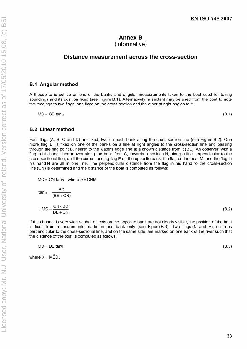
33
Annex B (informative)
Distance measurement across the cross-section
B.1 Angular method
A theodolite is set up on one of the banks and angular measurements taken to the boat used for taking soundings and its position fixed (see Figure B.1). Alternatively, a sextant may be used from the boat to note the readings to two flags, one fixed on the cross-section and the other at right angles to it.
MC = CE tanα (B.1)
B.2 Linear method
Four flags (A, B, C and D) are fixed, two on each bank along the cross-section line (see Figure B.2). One more flag, E, is fixed on one of the banks on a line at right angles to the cross-section line and passing through the flag point B, nearer to the water's edge and at a known distance from it (BE). An observer, with a flag in his hand, then moves along the bank from C, towards a position N, along a line perpendicular to the cross-sectional line, until the corresponding flag E on the opposite bank, the flag on the boat M, and the flag in his hand N are all in one line. The perpendicular distance from the flag in his hand to the cross-section line (CN) is determined and the distance of the boat is computed as follows:
MC = CN tanα where α = ˆCNM
BCtan(BE CN)
α =+
CN BCMCBE CN
×∴ =
+ (B.2)
If the channel is very wide so that objects on the opposite bank are not clearly visible, the position of the boat is fixed from measurements made on one bank only (see Figure B.3). Two flags (N and E), on lines perpendicular to the cross-sectional line, and on the same side, are marked on one bank of the river such that the distance of the boat is computed as follows:
MD = DE tanθ (B.3)
where θ = ˆMED .
EN ISO 748:2007
Lice
nsed
cop
y: M
r. N
UI U
ser,
Nat
iona
l Uni
vers
ity o
f Ire
land
, Ver
sion
cor
rect
as
of 1
7/05
/201
0 15
:08,
(c)
BS
I

34
B.3 Pivot-point method
When the river is wide and flat land is available, the pivot-point method may be used. In Figure B.4, the distance AP is approximately half the width of the river and PD is about one-fifth of AP. On line DD', points are marked at fixed intervals depending on the width between the selected verticals. The boat moving on line A A' can be fixed in the selected vertical by lining up with points P and E1, E2, etc. A second set of pivot-points on the other bank may be used if required. The computation is undertaken as follows:
AB DEPA PD
n n=
DE PAABPDn
n×
∴ = (B.4)
where n is the number of pivot points.
B.4 Other methods
Other methods using high technology such as Differential Global Positioning Systems (DGPS) are available.
Figure B.1 — Angular method
Figure B.2 — Linear method
EN ISO 748:2007
Lice
nsed
cop
y: M
r. N
UI U
ser,
Nat
iona
l Uni
vers
ity o
f Ire
land
, Ver
sion
cor
rect
as
of 1
7/05
/201
0 15
:08,
(c)
BS
I

35
Figure B.3 — Linear method from one bank
Key 1 pivot point 2 line of direction blocks 3 channel width 4 cross-section line
Figure B.4 — Pivot-point method
EN ISO 748:2007
Lice
nsed
cop
y: M
r. N
UI U
ser,
Nat
iona
l Uni
vers
ity o
f Ire
land
, Ver
sion
cor
rect
as
of 1
7/05
/201
0 15
:08,
(c)
BS
I

36
Annex C (informative)
Corrections for wetted length of wire when measuring depths with wire
not normal to surface
C.1 The following tables are based on Measurement and computation of streamflow, Vol. 1, Measurement of stage and discharge, the United States Geological Survey, Water Supply, Paper No. 2175, 1982. It should be noted that a correction must also be made for the change between the vertical length and the slant length of the line above the water surface. If the point of suspension of the sounding line is at a vertical distance X above the surface and the angle between the sounding line and vertical is a, then the air line correction k1a to be applied is given by the formula:
( )1 sec 1ak a X= − (C.1)
The percentage correction (k1a ⋅ 100/X) to be deducted from the measured length of the sounding line, for angles up to 30°, is given in Table C.1.
Table C.1 — Air-line correction
Vertical angle Correction
%
Vertical angle Correction
%
4° 0,24 18° 5,15
6° 0,55 20° 6,42
8° 0,98 22° 7,85
10° 1,54 24° 9,46
12° 2,23 26° 11,26
14° 3,06 28° 13,26
16° 4,03 30° 15,47
The wet-line correction k1w (see Table C.2), also expressed as a percentage to be deducted from the measured length of the sounding line, is estimated on the assumptions that the horizontal drag pressure on the weight in the comparatively still water near the bottom can be neglected, that the velocity distribution in the vertical is normal, and that the sounding wire and the weight are designed to offer little resistance to the water current.
The uncertainties in this estimation are such that significant errors may be introduced if the angle of the sounding wire with the vertical is more than 30°.
EN ISO 748:2007
Lice
nsed
cop
y: M
r. N
UI U
ser,
Nat
iona
l Uni
vers
ity o
f Ire
land
, Ver
sion
cor
rect
as
of 1
7/05
/201
0 15
:08,
(c)
BS
I

37
Table C.2 — Wet line correction
Vertical angle Correction
%
Vertical angle Correction
%
4° 0,06 18° 1,64
6° 0,16 20° 2,04
8° 0,32 22° 2,48
10° 0,50 24° 2,96
12° 0,72 26° 3,50
14° 0,98 28° 4,08
16° 1,28 30° 4,72
The corrections given in this table are percentages of the wet-line depth (see also ISO/TR 9209).
C.2 Figure C.1 shows a typical situation where the position of a current-meter is affected by the velocity of the water. The required position for the current-meter is at point B, a distance L from the point of suspension. The velocity of the water will cause the current-meter to be pulled downstream so that the angle of suspension is α.
W
W
cos
cos
cos
cos
LL
L L CL
L CLL C
LC L
α
α
α
α
=
= +
∴ =+
+ =
= −
Key 1 water level 2 point of suspension 3 bed level
Figure C.1 — Wet line correction
If the cross-section is pre-surveyed then the value of L is either known or can be measured on site. The angle α can be measured and the correction factor C calculated. The process may be iterative as the angle, α, may alter as the current-meter is lowered into the water.
EN ISO 748:2007
Lice
nsed
cop
y: M
r. N
UI U
ser,
Nat
iona
l Uni
vers
ity o
f Ire
land
, Ver
sion
cor
rect
as
of 1
7/05
/201
0 15
:08,
(c)
BS
I

38
This method assumes that the bed is horizontal between points D and D1.
If the cross-section is not pre-surveyed then the current-meter can be lowered to the bed at point D1 and the distance AD1 measured. At the same time the angle, α, can be measured and thus the distance AD can be calculated.
ADcosAD1
α = (C.2)
Thus:
AD AD1cosα= (C.3)
Having determined distance AD, the procedure used for a pre-surveyed cross-section can be used.
EN ISO 748:2007
Lice
nsed
cop
y: M
r. N
UI U
ser,
Nat
iona
l Uni
vers
ity o
f Ire
land
, Ver
sion
cor
rect
as
of 1
7/05
/201
0 15
:08,
(c)
BS
I

39
Annex D (informative)
Correction for drift
Where motor launches are used, they shall be of sufficient power to avoid drift under normal circumstances. In great depths and high velocities, it is sometimes impossible to keep the measuring launch exactly at the desired point. The upstream or downstream and lateral movements of the launch during velocity observation shall be measured by appropriate surveying techniques or electronic distance-measuring equipment, and a vector analysis made to determine the true velocity corrected for movement of the measuring launch.
For downstream drift in high velocities, the drift can be measured and due allowance made in the velocity measurement. For example, based on 388 observations carried out on the River Indus at Kotri (range of velocities between 1,146 m/s and 2,911 m/s), the correction for drift was obtained statistically using the following formula:
p b d0,060 0,98 0,98v v v= + + (D.1)
where
pv is the true velocity, in metres per second;
bv is the velocity, in metres per second, observed at the point with the boat drifting;
dv is the drift velocity, in metres per second.
In the above set of observations, the velocity without drift was observed by means of a sufficiently powered motor launch, while that with drift was observed by means of a flat-bottomed boat. A two-pronged anchor weighing 28,123 kg was used for partially anchoring the boat, the length of the rope paid out generally varying between 20 m and 25 m. After the boat was towed sufficiently upstream, the anchor was dropped, and the velocity was measured while the boat drifted.
The drift velocity was measured from drift flags fixed at known distances apart on both the banks.
EN ISO 748:2007
Lice
nsed
cop
y: M
r. N
UI U
ser,
Nat
iona
l Uni
vers
ity o
f Ire
land
, Ver
sion
cor
rect
as
of 1
7/05
/201
0 15
:08,
(c)
BS
I

40
Annex E (informative)
Uncertainties in the velocity-area measurement
E.1 General
See also Clause 9.
It should be noted that the values given in this annex are the result of investigations carried out since the publication of the first edition of this International Standard in 1968. In particular, reference should be made to ISO 1088. Nevertheless, it is recommended that each user should determine independently the values of the uncertainties which will apply to a particular case. The values in the tables are relative standard uncertainties (“one standard deviation” values, level of confidence approximately 68 %), expressed as percentages of the measured value.
The information given in the tables can also be used to determine the optimum observational procedure for a desired accuracy.
E.2 Uncertainties in width (ub)
The uncertainty in the measurement of width should be no greater than 0,5 %.
As an example, the error introduced for a particular range finder having a base distance of 800 mm varies approximately as given in Table E.1.
Table E.1 — Example of uncertainties for a range finder (Standard uncertainties, level of confidence approximately 68 %)
Range of width
m
Absolute error
m
Relative uncertainty
%
0 to 100 0 to 0,15 0,15
101 to 150 0,15 to 0,25 0,2
151 to 250 0,3 to 0.6 0,25
E.3 Uncertainties in depth (ud)
For depths up to 0,300 m, the uncertainly should not exceed 1,5 %, and for depths over 0,300 m, the uncertainty should not exceed 0,5 %.
As an example, the uncertainty in depth in an alluvial river whose depth varied from 2 m to 7 m and where the velocity varied up to 1,5 m/s was, for these conditions, of the order of 0,05 m measured using a suspension cable.
As another example, measurements of depth were taken with a sounding-rod up to a depth of 6 m, and beyond that value by a log line with standard air-line and wet-line corrections. These observations were made within the range of 0,087 m/s to 1,3 m/s, the results being as given in Table E.2.
EN ISO 748:2007
Lice
nsed
cop
y: M
r. N
UI U
ser,
Nat
iona
l Uni
vers
ity o
f Ire
land
, Ver
sion
cor
rect
as
of 1
7/05
/201
0 15
:08,
(c)
BS
I

41
Table E.2 — Examples of uncertainties in depth measurements (Standard uncertainties, level of confidence approximately 68 %)
Range of depth
m
Absolute uncertainty
m
Relative uncertainty
% Remarks
0,4 to 6
6 to 14
0,02
0,025
0,65
0,25
With sounding rod.
With log-line and air- and wet-line corrections.
NOTE Column 3 relative uncertainties were computed from column 2 absolute uncertainties using mid-range depths 3,2 m and 10 m.
E.4 Uncertainties in determination of the mean velocity
E.4.1 Times of exposure (ue)
The percentage uncertainty in point velocity measurement taken at different exposure times and points in the vertical, shown in Table E.3 are given as a guide and should be verified by the user.
Table E.3 — Percentage uncertainties in point velocity measurements due to limited exposure time (Standard uncertainties, level of confidence approximately 68 %)
Point in vertical
0,2D, 0,4D or 0,6D 0,8D or 0,9D
Exposure time
min
Velocity
m/s
0,5 1 2 3 0,5 1 2 3
0,050 25 20 15 10 40 30 25 20
0,100 14 11 8 7 17 14 10 8
0,200 8 6 5 4 9 7 5 4
0,300 5 4 3 3 5 4 3 3
0,400 4 3 3 3 4 3 3 3
0,500 4 3 3 2 4 3 3 2
1,000 4 3 3 2 4 3 3 2
over 1,000 4 3 3 2 4 3 3 2
EN ISO 748:2007
Lice
nsed
cop
y: M
r. N
UI U
ser,
Nat
iona
l Uni
vers
ity o
f Ire
land
, Ver
sion
cor
rect
as
of 1
7/05
/201
0 15
:08,
(c)
BS
I

42
E.4.2 Number of points in the vertical (up)
The uncertainty values shown in Table E.4 were derived from many samples of irregular vertical velocity curves. They are given as a guide and should be verified by the user.
Table E.4 — Percentage uncertainties in the measurement of mean velocity at a vertical, due to limited number of points in the vertical
(Standard uncertainties, level of confidence approximately 68 %)
Method of measurement Uncertainties
%
Velocity distribution 0,5
5 points (7.1.5.3.3) 2,5
2 points (0,2D and 0,8D) (7.1.5.3.2) 3,5
1 point (0,6D) (7.1.5.3.3) 7,5
Surface (7.1.5.3.5) 15
E.4.3 Rotating-element current-meter rating (uc)
The uncertainty values shown in Table E.5 are given as a guide and are based on experiments performed in several of the world’s rating tanks.
Table E.5 — Percentage uncertainties in point velocity measurement due to current-meter rating error (Standard uncertainties, level of confidence approximately 68 %)
Uncertainties
% Velocity measured
m/s Individual rating Group or standard rating
0,03 10 10
0,10 2,5 5
0,12 1,25 2,5
0,25 1,0 2
0,50 0,5 1,5
Over 0,50 0,5 1,0
EN ISO 748:2007
Lice
nsed
cop
y: M
r. N
UI U
ser,
Nat
iona
l Uni
vers
ity o
f Ire
land
, Ver
sion
cor
rect
as
of 1
7/05
/201
0 15
:08,
(c)
BS
I

43
E.4.4 Number of verticals (um)
The uncertainty values in Table E.6 are given as a guide and should be verified by the user.
Table E.6 — Percentage uncertainties in the measurement of mean velocity due to the limited number of verticals
(Standard uncertainties, level of confidence approximately 68 %)
Number of verticals Uncertainties
%
5 7,5
10 4,5
15 3,0
20 2,5
25 2,0
30 1,5
35 1,0
40 1,0
45 1,0
EN ISO 748:2007
Lice
nsed
cop
y: M
r. N
UI U
ser,
Nat
iona
l Uni
vers
ity o
f Ire
land
, Ver
sion
cor
rect
as
of 1
7/05
/201
0 15
:08,
(c)
BS
I

44
Annex F (informative)
Determination of mean velocity from float measurements
F.1 Establishment of cross-sections
Two parallel cross-sections AB and CD are selected as shown in Figure F.1, their positions indicated by flags or markers. For the purpose of the measurement, markers A and C or A and D must be easily accessible and all should be visible from points A and C or A and D. The distance ac between the cross-sections should be at least twice the channel width and, for ease of computation, each should be aligned perpendicular to the flow direction. Distances AB, CD, AC and ac are determined by topographic surveys.
Note that in the above discussion, it is assumed that distances AC = ac.
F.2 Velocity measurements
The observer stations himself at point C equipped with a double stopwatch and on his signal a float is thrown into the channel upstream of cross-section AB. An assistant at point A takes a line of sight along AB and when the float crosses the line, signals to the observer who immediately starts both watches. The first of these is stopped when the float crosses his line of sight along CB and the second when the float reaches CD. Accordingly, t is the time taken for the float to traverse distance ab (reading from the first stopwatch) and T the time taken to cover distance ac (reading from the second stopwatch). In this way, it is possible to compute the float velocity, assuming a straight path and uniform velocity.
ab ACut T
= = (F.1)
where u is the float velocity, in metres per second.
Note that again it is assumed that distances AC = ac.
F.3 Determination of position of float in the cross-section
Taking the example in Figure F.1 to determine distance aB: ABC and aBb are similar triangles and therefore, assuming uniform float velocity, the ratios of their sides will be equal to the ratio T:t.
Thus:
aBAB
tT
= (F.2)
Hence:
ABaB tT⋅
= (F.3)
EN ISO 748:2007
Lice
nsed
cop
y: M
r. N
UI U
ser,
Nat
iona
l Uni
vers
ity o
f Ire
land
, Ver
sion
cor
rect
as
of 1
7/05
/201
0 15
:08,
(c)
BS
I
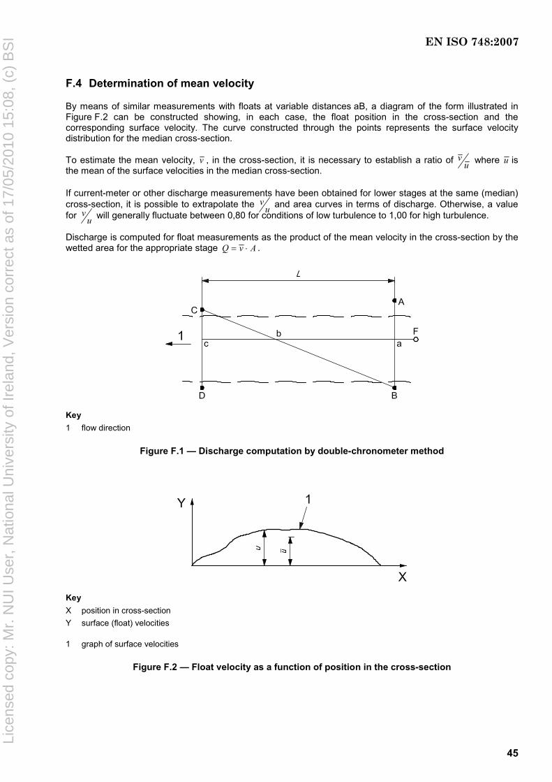
45
F.4 Determination of mean velocity
By means of similar measurements with floats at variable distances aB, a diagram of the form illustrated in Figure F.2 can be constructed showing, in each case, the float position in the cross-section and the corresponding surface velocity. The curve constructed through the points represents the surface velocity distribution for the median cross-section.
To estimate the mean velocity, v , in the cross-section, it is necessary to establish a ratio of vu where u is
the mean of the surface velocities in the median cross-section.
If current-meter or other discharge measurements have been obtained for lower stages at the same (median) cross-section, it is possible to extrapolate the v
u and area curves in terms of discharge. Otherwise, a value for v
u will generally fluctuate between 0,80 for conditions of low turbulence to 1,00 for high turbulence.
Discharge is computed for float measurements as the product of the mean velocity in the cross-section by the wetted area for the appropriate stage Q v A= ⋅ .
Key 1 flow direction
Figure F.1 — Discharge computation by double-chronometer method
Key X position in cross-section Y surface (float) velocities
1 graph of surface velocities
Figure F.2 — Float velocity as a function of position in the cross-section
EN ISO 748:2007
Lice
nsed
cop
y: M
r. N
UI U
ser,
Nat
iona
l Uni
vers
ity o
f Ire
land
, Ver
sion
cor
rect
as
of 1
7/05
/201
0 15
:08,
(c)
BS
I

46
Bibliography
[1] ISO 1000, SI units and recommendations for the use of their multiples and of certain other units
[2] ISO 1100-1, Measurement of liquid flow in open channels — Part 1: Establishment and operation of a gauging station
[3] ISO 1100-2, Measurement of liquid flow in open channels — Part 2: Determination of the stage-discharge relation
[4] ISO 3454, Hydrometry — Direct depth sounding and suspension equipment
[5] ISO 4366, Hydrometry — Echo sounders for water depth measurements
[6] ISO 4369, Measurement of liquid flow in open channels — Moving-boat method
[7] ISO 4373, Hydrometry — Water level measuring devices
[8] ISO 4375, Hydrometric determinations — Cableway systems for stream gauging
[9] ISO 5168, Measurement of fluid flow — Procedures for the evaluation of uncertainties
[10] ISO 9196, Liquid flow measurement in open channels — Flow measurements under ice conditions
[11] ISO/TR 9209, Measurement of liquid flow in open channels — Determination of the wetline correction
[12] Guide to the expression of uncertainty in measurement (GUM), BIPM, IEC, IFCC, ISO, IUPAC, IUPAP, OIML, 19932)
[13] RANTZ, S.E. et al. USGS Water Supply Paper 2175 — Measurement and computation of discharge, Volume 1 — Measurement of stage and discharge, 1982
2) Corrected and reprinted in 1995. To be republished as ISO/IEC Guide 98-3.
EN ISO 748:2007
Lice
nsed
cop
y: M
r. N
UI U
ser,
Nat
iona
l Uni
vers
ity o
f Ire
land
, Ver
sion
cor
rect
as
of 1
7/05
/201
0 15
:08,
(c)
BS
I

blank
Lice
nsed
cop
y: M
r. N
UI U
ser,
Nat
iona
l Uni
vers
ity o
f Ire
land
, Ver
sion
cor
rect
as
of 1
7/05
/201
0 15
:08,
(c)
BS
I

Lice
nsed
cop
y: M
r. N
UI U
ser,
Nat
iona
l Uni
vers
ity o
f Ire
land
, Ver
sion
cor
rect
as
of 1
7/05
/201
0 15
:08,
(c)
BS
I
BS EN ISO 748:2007BSI389 Chiswick High RoadLondonW4 4AL
BSI — British Standards InstitutionBSI is the independent national body responsible for preparing British Standards. It presents the UK view on standards in Europe and at the international level. It is incorporated by Royal Charter.
Revisions
British Standards are updated by amendment or revision. Users of British Standards should make sure that they possess the latest amendments or editions.
It is the constant aim of BSI to improve the quality of our products and services. We would be grateful if anyone finding an inaccuracy or ambiguity while using this British Standard would inform the Secretary of the technical committee responsible, the identity of which can be found on the inside front cover. Tel: +44 (0)20 8996 9000. Fax: +44 (0)20 8996 7400.
BSI offers members an individual updating service called PLUS which ensures that subscribers automatically receive the latest editions of standards.
Buying standards
Orders for all BSI, international and foreign standards publications should be addressed to Customer Services. Tel: +44 (0)20 8996 9001. Fax: +44 (0)20 8996 7001. Email: [email protected]. Standards are also available from the BSI website at http://www.bsi-global.com.
In response to orders for international standards, it is BSI policy to supply the BSI implementation of those that have been published as British Standards, unless otherwise requested.
Information on standards
BSI provides a wide range of information on national, European and international standards through its Library and its Technical Help to Exporters Service. Various BSI electronic information services are also available which give details on all its products and services. Contact the Information Centre. Tel: +44 (0)20 8996 7111. Fax: +44 (0)20 8996 7048. Email: [email protected].
Subscribing members of BSI are kept up to date with standards developments and receive substantial discounts on the purchase price of standards. For details of these and other benefits contact Membership Administration. Tel: +44 (0)20 8996 7002. Fax: +44 (0)20 8996 7001. Email: [email protected].
Information regarding online access to British Standards via British Standards Online can be found at http://www.bsi-global.com/bsonline.
Further information about BSI is available on the BSI website at http://www.bsi-global.com.
Copyright
Copyright subsists in all BSI publications. BSI also holds the copyright, in the UK, of the publications of the international standardization bodies. Except as permitted under the Copyright, Designs and Patents Act 1988 no extract may be reproduced, stored in a retrieval system or transmitted in any form or by any means – electronic, photocopying, recording or otherwise – without prior written permission from BSI.
This does not preclude the free use, in the course of implementing the standard, of necessary details such as symbols, and size, type or grade designations. If these details are to be used for any other purpose than implementation then the prior written permission of BSI must be obtained.
Details and advice can be obtained from the Copyright & Licensing Manager. Tel: +44 (0)20 8996 7070. Fax: +44 (0)20 8996 7553. Email: [email protected].