hydrogeologic assessment proposed pole yard · hydrogeologic assessment proposed pole yard...
TRANSCRIPT
Hydrogeologic Assessment
Proposed Pole Yard
Arlington, Washington
for Snohomish County PUD No. 1
April 26, 2016

Hydrogeologic Assessment
Proposed Pole Yard
Arlington, Washington
for Snohomish County PUD No. 1
April 26, 2016
8410 154th Avenue NE Redmond, Washington 98052 425.861.6000
April 26, 2016 | Page i File No. 0482-051-03
Table of Contents INTRODUCTION ....................................................................................................................................................... 1
SCOPE OF SERVICES ............................................................................................................................................. 1
SITE DESCRIPTION AND LOCATION ...................................................................................................................... 2
PROPOSED LAND USE ACTIVITES ......................................................................................................................... 2
Pole and Transformer Storage .......................................................................................................................... 3
OVERVIEW OF GEOLOGIC AND HYDROGEOLOGIC CONDITIONS ......................................................................... 3
General Geology ................................................................................................................................................. 3 Hydrogeologic Conditions .................................................................................................................................. 4
Recharge ..................................................................................................................................................... 5 Surface Water Bodies ................................................................................................................................. 5 Water Supplies ............................................................................................................................................ 5 Water Quality ............................................................................................................................................... 5
HYDROGEOLOGIC SITE EVALUATION .................................................................................................................... 6
Soil Texture, Permeability, and Contaminant Attenuation Properties ............................................................ 6 Characteristics of the Unsaturated Soil ............................................................................................................ 6 Depth to Groundwater ....................................................................................................................................... 7 Aquifer Properties .............................................................................................................................................. 8 Potential Impacts to the Aquifer or Groundwater ............................................................................................ 8
Hazardous Materials ................................................................................................................................... 9
CONCLUSIONS AND RECOMMENDATIONS .......................................................................................................... 9
LIMITATIONS ......................................................................................................................................................... 10
REFERNECES ....................................................................................................................................................... 10
LIST OF FIGURES
Figure 1. Vicinity Map Figure 2. Site Plan Figure 3. Water Level Data Figure 4. Well Location Map
APPENDICES
Appendix A. Water Well Reports Figure A-1 – Albert Kluin Sr Well Figure A-2 – Atonement Free Lutheran Well Figure A-3 – Bud Nold Well Figure A-4 – Canus Investment Corp (100 feet deep) Figure A-5 – Canus Investment Corp (217 feet deep) Figure A-6 – City of Arlington, Airport Well Figure A-7 – Elwood R Falor Well Figure A-8 – Gary Bohanon Well
Appendix B. Report Limitations and Guidelines for Use

April 26, 2016 | Page 1 File No. 0482-051-03
INTRODUCTION
This report presents the results of our hydrogeologic assessment of the proposed Snohomish County Public Utility District No. 1 (Snohomish County PUD) Pole Yard project located between 172nd Street NE and 180th Street NE, east of 59th Avenue NE and west of the Burlington-Northern Santa Fe (BNSF) railroad in Arlington, Washington. The project location is shown on the Vicinity Map, Figure 1. The preliminary layout of the Proposed Pole Yard is shown relative to surrounding physical features on the Site Plan, Figure 2.
We previously prepared a draft geotechnical report for the project titled, “Geotechnical Engineering Services, Local Office Replacement and Substation, Arlington, Washington,” dated May 20, 2013. Additionally, we have been monitoring groundwater levels at the site since February 2013. This report is based on our previous experience at the site and discussions with Snohomish County PUD.
We understand that a portion of the site is being developed for a permanent treated-pole and transformer storage area (Pole Yard). Development of this Pole Yard will include constructing gravel laydown areas and asphalt-paved roadways. We understand that the transformer storage area will be paved and curbed, with stormwater captured and routed to an on-site oil stop valve.
This hydrogeologic site assessment is provided for the evaluation of the potential groundwater impacts from the proposed Pole Yard on Snohomish PUD property (the site). The City of Arlington (City) requires that a hydrogeologic site assessment be completed for this project because it is located within the 1-year time-of-travel wellhead protection zone associated with a City of Arlington water-supply well, referred to as the Airport Well. The City requires submitting a written assessment that details the hydrogeologic characteristics and subsurface conditions and indicates the susceptibility and potential for contamination of groundwater supplies. The report will be prepared to meet the requirements of a hydrogeologic site assessment per Arlington Municipal Code, Chapter 20.93.
SCOPE OF SERVICES
Proposed project activities include permanent treated-pole and transformer storage facilities. Our scope of services for this task includes the following:
1. Reviewing available published and site-specific reports and other information regarding the geologicsetting, hydrogeology and background water quality of the site and vicinity.
2. Reviewing available well and borehole data within 1,000 feet of the site.
3. Estimating groundwater elevations, recharge potential, flow direction and gradient. Three groundwatermonitoring points are needed to estimate the direction of groundwater flow beneath the site. There aretwo existing groundwater monitoring wells on the site. Access to another well that is completed withinthe shallow recessional outwash aquifer (less than approximately 50 feet below ground surface) isneeded for an accurate flow direction and gradient.
4. Completing a brief site visit to observe geologic conditions, nearby surface water features and springs.
5. Preparing an evaluation of the risk of the hazardous materials to be stored on the facility. If we findthat there are potential risks or impacts to critical public aquifer storage recharge areas, we will provide

April 26, 2016 | Page 2 File No. 0482-051-03
a discussion of alternatives to avoid or prevent the impacts. We will also describe and list best management practices (BMP) plans.
6. Preparing a hydrogeologic site assessment report by a qualified licensed hydrogeologist. We will submita draft report to Snohomish County PUD for internal review and comment. After comments arediscussed and incorporated, we will produce the final report for submittal to the City. The report will bebased on the City’s requirements that include descriptions of:
Soil texture, permeability, and contaminant attenuation properties;
Characteristics of the unsaturated top layer of soil, the vadose zone, and geologic material,including permeability and attenuation properties;
Depth to groundwater and/or impermeable soil layer;
Aquifer properties such as hydraulic conductivity and gradients; and
Potential impacts to the aquifer or groundwater.
We received information from Snohomish PUD on the substances used to treat power poles, a preliminary design plan for the Pole Yard, and general descriptions of the proposed facility uses and on-site handling or storage of hazardous materials. Other sources of information are listed in the Bibliography at the end of this report.
SITE DESCRIPTION AND LOCATION
The site is located approximately 2.8 miles south of the Stillaguamish River within the city limits of Arlington, Washington. Topographically, the site is located within the Marysville Trough, which is a north-south trending lowland that extends from the Stillaguamish River to approximately one mile south of the City of Marysville.
The 25.6-acre site is relatively flat, and is currently undeveloped other than a temporary pole storage yard at the western edge of the property. The site grade ranges from about Elevation 140 feet1 in the northeast corner to Elevation 131 feet in the southwest corner. Vegetation on the site consists of recently mowed blackberry brambles, shrubs and scattered deciduous and conifer trees. An abandoned barn is located near the center of the property. The locations of adjacent roads and railroad, the proposed Pole Yard, and locations of boreholes and test pits related to our 2013 geotechnical study are shown on the Site Plan, Figure 2.
PROPOSED LAND USE ACTIVITES
A Pole Yard operated by Snohomish PUD is proposed for the site. Our understanding of the site activities are based on information provided by Ben Davis, PE of Snohomish PUD. The following activities are proposed:
■ Treated power-pole storage
1 Note that all elevations provided in the report are relative to the North American Vertical Datum 1988 (NAVD88).
April 26, 2016 | Page 3 File No. 0482-051-03
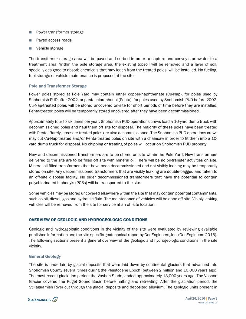
■ Power transformer storage
■ Paved access roads
■ Vehicle storage
The transformer storage area will be paved and curbed in order to capture and convey stormwater to a treatment area. Within the pole storage area, the existing topsoil will be removed and a layer of soil, specially designed to absorb chemicals that may leach from the treated poles, will be installed. No fueling, fuel storage or vehicle maintenance is proposed at the site.
Pole and Transformer Storage
Power poles stored at Pole Yard may contain either copper-naphthenate (Cu-Nap), for poles used by Snohomish PUD after 2002, or pentachlorophenol (Penta), for poles used by Snohomish PUD before 2002. Cu-Nap-treated poles will be stored uncovered on-site for short periods of time before they are installed. Penta-treated poles will be temporarily stored uncovered after they have been decommissioned.
Approximately four to six times per year, Snohomish PUD operations crews load a 10-yard dump truck with decommissioned poles and haul them off site for disposal. The majority of these poles have been treated with Penta. Rarely, creosote-treated poles are also decommissioned. The Snohomish PUD operations crews may cut Cu-Nap-treated and/or Penta-treated poles on site with a chainsaw in order to fit them into a 10-yard dump truck for disposal. No chipping or treating of poles will occur on Snohomish PUD property.
New and decommissioned transformers are to be stored on site within the Pole Yard. New transformers delivered to the site are to be filled off site with mineral oil. There will be no oil-transfer activities on site. Mineral-oil-filled transformers that have been decommissioned and not visibly leaking may be temporarily stored on site. Any decommissioned transformers that are visibly leaking are double-bagged and taken to an off-site disposal facility. No older decommissioned transformers that have the potential to contain polychlorinated biphenyls (PCBs) will be transported to the site.
Some vehicles may be stored uncovered elsewhere within the site that may contain potential contaminants, such as oil, diesel, gas and hydraulic fluid. The maintenance of vehicles will be done off site. Visibly leaking vehicles will be removed from the site for service at an off-site location.
OVERVIEW OF GEOLOGIC AND HYDROGEOLOGIC CONDITIONS
Geologic and hydrogeologic conditions in the vicinity of the site were evaluated by reviewing available published information and the site-specific geotechnical report by GeoEngineers, Inc. (GeoEngineers 2013). The following sections present a general overview of the geologic and hydrogeologic conditions in the site vicinity.
General Geology
The site is underlain by glacial deposits that were laid down by continental glaciers that advanced into Snohomish County several times during the Pleistocene Epoch (between 2 million and 10,000 years ago). The most recent glaciation period, the Vashon Stade, ended approximately 13,000 years ago. The Vashon Glacier covered the Puget Sound Basin before halting and retreating. After the glaciation period, the Stillaguamish River cut through the glacial deposits and deposited alluvium. The geologic units present in
April 26, 2016 | Page 4 File No. 0482-051-03
the project vicinity are, from youngest to oldest: River Alluvium (Qal), Vashon Recessional Outwash (Qvr), Vashon Till (Qvt), Vashon Advance Outwash (Qva), Transitional Beds (Qtb), and Older Gravel (Qog). The following unit descriptions are from Thomas et al. (1997):
■ The Qal unit is composed of fluvial deposits from the Stillaguamish River deposited after the glaciation period. Alluvium consists primarily of sand with some gravel, with lenses of fine-grained overbank deposits, gravel and cobbles. The alluvium is typically 40 feet thick near the river.
■ The Qvr unit was deposited by the retreating glacier, and covers most of the Marysville Trough. The Qvr is composed of moderately to well-sorted gravel and sand that grades to silt and is typically 40 to 250 feet thick.
■ The Qvt unit underlies the Qvr and was deposited by the advancing glacier overriding and reworking older deposits and rocks. Glacial till is compact and typically consists of an unsorted combination of clay- through cobble-sized sediments. The average thickness of Qvt is about 70 feet, but can range from 0 to 250 feet thick.
■ The Qva unit underlies the Qvt. The Qva was deposited by meltwater originating from the advancing glacier. The Qva typically has fine-grained sediments that grade upward into coarse-grained deposits. The advance outwash is typically 120 feet thick and up to 350 feet thick.
■ The Qtb underlies the Qva. The Qtb is an interglacial unit that was deposited in a low energy environment, consisting of fine-grained materials of sandy to silty clay, with lenses of sand and gravel. The Qtb unit is typically 100 feet thick, up to 400 feet thick.
■ The Qog unit underlies the Qtb and is comprised of a wide range of generally coarse-grained sands and gravels. The typical thickness of Qog is about 500 feet, but it can be as thick as 1,000 feet.
Hydrogeologic Conditions
There are four aquifers in the project vicinity: the Alluvial Aquifer, the Vashon Recessional Aquifer, the Vashon Advance Aquifer and the Deep Aquifer.
The Alluvial Aquifer is shallow and is in direct contact with the Stillaguamish River (Pacific Groundwater Group 2007a). The Alluvial Aquifer extends nearly 2 miles south of the present-day location of the Stillaguamish River, but is not present within ¼-mile of the project site, according to mapping by Minard (1985).
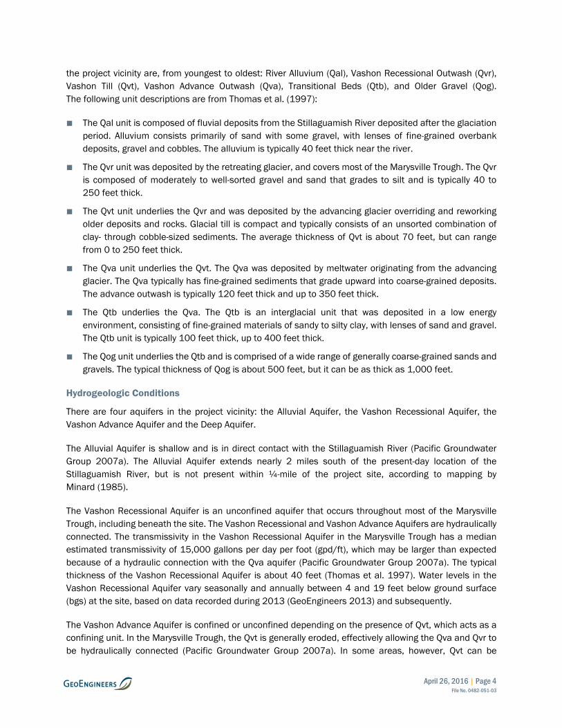
The Vashon Recessional Aquifer is an unconfined aquifer that occurs throughout most of the Marysville Trough, including beneath the site. The Vashon Recessional and Vashon Advance Aquifers are hydraulically connected. The transmissivity in the Vashon Recessional Aquifer in the Marysville Trough has a median estimated transmissivity of 15,000 gallons per day per foot (gpd/ft), which may be larger than expected because of a hydraulic connection with the Qva aquifer (Pacific Groundwater Group 2007a). The typical thickness of the Vashon Recessional Aquifer is about 40 feet (Thomas et al. 1997). Water levels in the Vashon Recessional Aquifer vary seasonally and annually between 4 and 19 feet below ground surface (bgs) at the site, based on data recorded during 2013 (GeoEngineers 2013) and subsequently.
The Vashon Advance Aquifer is confined or unconfined depending on the presence of Qvt, which acts as a confining unit. In the Marysville Trough, the Qvt is generally eroded, effectively allowing the Qva and Qvr to be hydraulically connected (Pacific Groundwater Group 2007a). In some areas, however, Qvt can be

April 26, 2016 | Page 5 File No. 0482-051-03
between 70 and 250 feet thick (Thomas et al. 1997) and can act as a confining unit between the Vashon Recessional and Vashon Advance Aquifers.
The Deep Aquifer is confined by the Qtb and has a top elevation from about 100 feet to below –400 feet. The median value of transmissivity for the Deep Aquifer is 3,300 gpd/ft (Pacific Groundwater Group 2007a). In the vicinity of the site, the top of the Deep Aquifer is 100 feet bgs, and water levels are at about 102 feet bgs.
Recharge
Recharge to the aquifers is primarily by infiltration and percolation of precipitation. Average annual recharge to the groundwater by infiltration and percolation is estimated to be approximately 24 inches per year in the vicinity of the City of Arlington (Thomas et al. 1997). According to the same source, the average minimum permeability is 1.3 inches per hour for outwash deposits. The recharge potential for the proposed Pole Yard is high based on the relatively permeable surface and subsurface soils (Thomas et al. 1997).
Surface Water Bodies
Slightly more than ¼ mile south of the site is an ephemeral drainage to the Middle Fork Quilceda Creek, which is not a salmon-bearing stream within the nearby reach (DNR 2016).
Water Supplies
The City of Arlington’s water supply is obtained from the Haller Wellfield, the Airport Well, and an intertie between Snohomish PUD and the City of Everett (City of Arlington 2016). The Haller Wellfield is located adjacent to the Stillaguamish River, approximately 3 miles north of the Pole Yard site. The Airport Well is located approximately ½ mile northwest of the project site. The source of the Airport Well is the Deep Aquifer (Pacific Groundwater Group 2007a).
Other water-supply wells exist within the site vicinity; according to Ecology records, there are seven water-supply wells within ¼ mile of the site boundary. No springs were identified within ¼ mile from the site. The monitoring wells installed on site by GeoEngineers in 2012 are completed within the Vashon Recessional Aquifer.
Water Quality
A USGS study conducted in 1992-1993 (Thomas et al. 1997) found the groundwater quality in Snohomish County to be generally good. Water quality was observed to be soft or moderately hard, and dissolved solids concentrations ranged between 36 to 1,040 milligrams per liter (mg/L) with a median of 133 mg/L. The groundwater system had no widespread groundwater contamination, although some contamination was possible because of the presence of agriculture and septic systems.
High natural concentrations of iron and manganese, two secondary (aesthetic) contaminants, were common. High iron and manganese have been detected in some water systems near the site, including the City’s Arlington Well (Washington Department of Health database 2016). Near Arlington, detectable arsenic was found with concentrations that ranged from less than 1 to 280 micrograms per liter (µg/L) and a median of 2 µg/L.

April 26, 2016 | Page 6 File No. 0482-051-03
HYDROGEOLOGIC SITE EVALUATION
The following summary of findings is provided to address the City of Arlington’s hydrogeologic site evaluation requirements as listed in Arlington Municipal Code (AMC), Chapter 20.93, Part IX Aquifer Recharge Areas (AMC 20.93.930).
A portion of the subject site is located within the 1-year time-of-travel zone of the Airport Well (Pacific Groundwater Group 2007b). Although the Wellhead Protection and Watershed Control Program (RH2 2016) recommends the evaluation of restricting land uses with the 1-year time-of-travel zone through a wellhead protection ordinance, no ordinance currently exists.
Soil Texture, Permeability, and Contaminant Attenuation Properties
On-site subsurface explorations consisted of six borings (B-1 through B-6) and eight test pits (TP-1 through TP-8) conducted by GeoEngineers (2013). The borings were drilled in 2012 to depths of 26½ to 51½ feet bgs and the test pits were excavated to depths ranging from 11 to 12 feet below the existing site grade. The approximate locations of the explorations are shown on the Site Plan, Figure 2.
Based on the explorations completed at the site, the subsurface conditions generally consist of a thin layer of silty sand overlying recessional outwash (Qvr) deposits. At the surface, we observed 4 to 8 inches of topsoil with roots overlying either fill or native recessional outwash deposits. The topsoil thickness was measured to be 4 inches at four locations and 8 inches in one location across the proposed Pole Yard. A 2-foot thick layer of disturbed native soils was observed in test pits TP-2 through TP-8. A 4-foot-thick layer of disturbed native soils or fill was observed in Boring B-4. The fill or disturbed native soils consist of loose silty sand, with occasional gravel. The fill/disturbed native soils overlie native glacially deposited recessional outwash (Marysville Sand Member) consisting of medium dense to dense sand, with variable silt and gravel content. Recessional outwash soils (Qvr) were observed to the full depth explored.
The permeability of the recessional outwash in Snohomish County is conservatively estimated to be 1.3 inches per hour (Thomas et al. 1997). The moderate to high permeability of the soil increases the susceptibility of the underlying aquifer to contamination from the ground surface. However, the concentration of contaminants reaching the water table may be reduced by attenuation processes occurring within the vadose zone.
Attenuation processes include biodegradation, dispersion, dilution and sorption and chemical and biological stabilization (EPA 1998). Because the water table in the recessional outwash aquifer is relatively shallow, attenuation of contaminants has a relatively short distance in which to occur before they reach the water table. Biodegradation is the most important attenuation mechanism (EPA 1998), with the organic-material content of the soil affecting contaminant attenuation and transport. The upper layer of the natural soils will be removed from the Pole Yard and replaced by soils specially selected for their attenuation properties beneath permeable areas. The treatment layer will comply with the current (2012) Ecology Stormwater Manual for Western Washington for enhanced treatment.
Characteristics of the Unsaturated Soil
The surface unsaturated soil is mapped as recessional outwash, which is medium dense to dense sand with variable silt and gravel. A 2- to 4-foot-thick layer of disturbed native soils or fill that consists of loose silty sand with occasional gravel was encountered overlying the recessional outwash. Beneath the surface

April 26, 2016 | Page 7 File No. 0482-051-03
layer, at least between 7½ and 12 feet of unsaturated recessional outwash was encountered in 2012 (GeoEngineers 2012). The thickness of the unsaturated zone varies with fluctuating groundwater levels, as discussed below. The depth to the bottom of the aquifer was not clearly defined by previous explorations on site.
Depth to Groundwater
In 2012, groundwater was observed to range from 7 to 12 feet bgs (Elevation 121 to 129 feet). Based on water level data between 2013 and 2016 at the two monitoring wells installed on site in the shallow Vashon Recessional Aquifer, the water levels fluctuate seasonally up to 14 feet and depths range from 4 to 19 feet bgs (Elevation 115 to 131 feet) (Water Level Data, Figure 3).
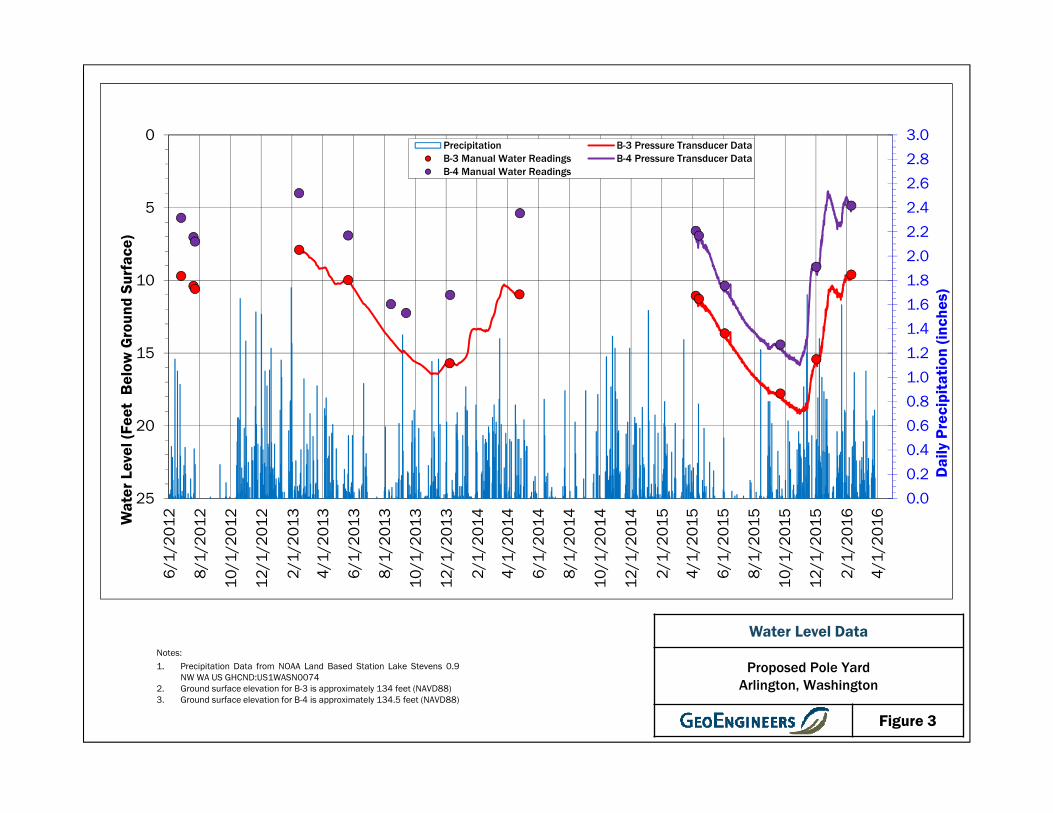
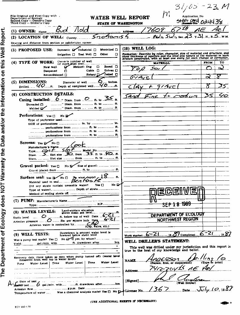
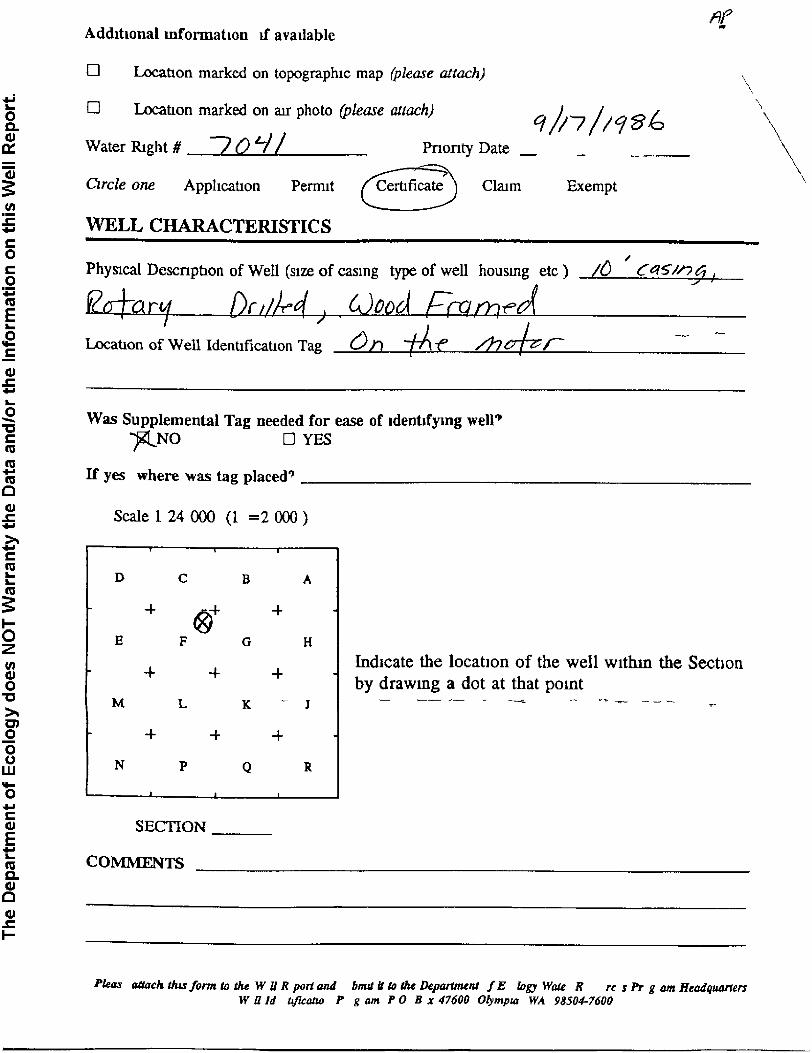
Our review of Washington State Department of Ecology (Ecology) Water Well Reports available on their Well Log Viewer website indicates that there are several records of water-supply wells located within ¼ mile of the site. Locations of the wells provided on the logs are typically to the nearest quarter-quarter section and are generally considered approximate. According to Ecology records summarized in Table 1 below, there are eight water-supply wells that potentially could be located within a ¼ mile of the property (Well Location Map, Figure 4). These wells are reportedly drilled to depths ranging from 38 to 217 feet bgs, with water levels ranging from 12 to 217 feet below the top of wells.
TABLE 1. SUMMARY OF WATER-SUPPLY WELLS WITHIN THE SITE VICINITY
Well Owner Well
Depth (feet, bgs)
Well Diameter (inches)
Water Level
(feet, bgs)
Completion Date
State Plane Coordinates
Easting Northing
Albert Kluin Sr 38 36 - 05/26/1952 1239205 1032849
Atonement Free Lutheran
40 6 12 10/12/1987 1240489 1032802
Bud Nold 40 6 - 06/21/1989 1240524 1034132
Canus Investment Corp. 217 6 217 10/04/1980 1240563 1035461
Canus Investment Corp. 100 6 12 08/15/1980 1240563 1035461
City of Arlington1 185 10 102 08/1945 1236680 1035611
Elwood R Falor 46 6 - 09/14/1957 1239262 1035509
Gary Bohanon 40 6 - 12/06/1989 1240489 1032802
1 According to the Wellhead Protection Memorandum (Pacific Groundwater Group 2007b), the City of Arlington’s Airport Well is located
approximately 2,100 feet from the border of the Snohomish PUD site.
In addition to these eight water wells, 126 resource protection wells and dewatering wells that range from 12 to 217 feet deep are listed by Ecology within ¼ mile of the Pole Yard site. The dewatering wells and most of the resource protection wells have likely been decommissioned based on Ecology well log records. Most of the resource protection wells are associated with Welco Lumber. The only known active water supply wells are owned by the Arlington Water Department (Group A), referred to in this report as the Airport

April 26, 2016 | Page 8 File No. 0482-051-03
Well, and the Atonement Free Lutheran Church (Group B). Most of these wells do not have accurate locations beyond the typical quarter-quarter section. The Water Well Reports for these wells indicate that groundwater within the Vashon Recessional Aquifer is approximately 10 feet below ground surface. Copies of Water Well Reports for these wells are included in Appendix A.
Aquifer Properties
Pacific Groundwater Group (2007b) conducted a capture zone study in the vicinity of the City of Arlington, and characterized the three aquifers that are the source of the City’s water supply: the Alluvial Aquifer, the Vashon Advance Aquifer, and the Deep Aquifer. The values for primary aquifer parameters determined from their study are presented in Table 2 below. The flow direction for the Deep Aquifer near the site is to the northwest towards the Stillaguamish River. The unconfined Vashon Recessional Aquifer beneath the site likely has a similar flow direction as the Deep Aquifer.
TABLE 2. AQUIFER PARAMETERS
Name
Hydraulic Conductivity
K
Hydraulic Gradient
i
Effective Porosity
ne
(feet per day) (feet per foot) (ft³/ft³)
Alluvial Aquifer 3,119 0.002 0.27
Vashon Recessional Aquifer
180 0.011 0.27
Vashon Advance Aquifer 40 0.016 0.27
Deep Aquifer 134 0.05 0.27
Notes:
Data from Pacific Groundwater Group (2007b)
We were not able to access a third well completed in the shallow Vashon Recessional Aquifer. Therefore, a site-specific hydraulic gradient and flow direction were not obtained. However, the on-site monitoring wells B-3 and B-4 are approximately 935 feet apart and the water elevation from B-3 was 5.2 feet lower than the water elevation in B-4 on February 9, 2016, consistent with a northwest flowing aquifer. The water levels in the two wells indicate a two-dimensional gradient of 0.005 feet per foot. Based on this estimated gradient and depth to groundwater measurements, we anticipate that groundwater levels below the proposed Pole Yard will be greater than 5 feet below existing grade.
Potential Impacts to the Aquifer or Groundwater
Because of the high permeability of the recessional outwash and the shallow depth to groundwater, the site is susceptible to shallow groundwater contamination. The source aquifer for the Airport Well is the Deep Aquifer encountered at a depth of 112 feet bgs. In order for contamination to reach the Deep Aquifer it would have to travel down through the unconfined shallow Vashon Recessional Aquifer and through a confining layer that is 9-foot-thick and consists of fine sand and clay at the well location. The confining unit therefore provides protection from contaminants potentially released at the surface.

April 26, 2016 | Page 9 File No. 0482-051-03
Hazardous Materials
Snohomish PUD no longer uses Penta- or creosote-treated wood poles. These products are being phased out of use as old poles are replaced with newer ones. The use of Penta and creosote to treat and preserve wood poles has been replaced by Cu-Nap. Cu-Nap is a non-restricted oil-borne wood preservative used to protect wood from decay by microorganisms and wood-eating insects.
Cu-Nap concentrate is classified as a “general use” pesticide by the United States Environmental Protection Agency (EPA) under the Federal Insecticide, Fungicide and Rodenticide Act (FIFRA). It has been standardized for use by the American Wood Protection Association (AWPA) (EPA Reg. No. 71992-1-54471). General use pesticides are those that are not classified by EPA for restricted use (40 CFR 152.175). The FIFRA requires that all pesticides sold or distributed in the United States be registered by the EPA. Registration is based on evaluation of scientific data and assessment of risks and benefits of a product's use. Cu-Nap-treated poles will be stored at the site according to all applicable regulations.
There will be no storage or application of concentrated Cu-Nap or Penta or PCBs at the site (personal communication Ben Davis, Snohomish PUD, March 15, 2016). Equipment (vehicles or transformers) will be inspected for leaks prior to being stored at the site. Any leaking equipment will be assessed and taken to an off-site facility.
CONCLUSIONS AND RECOMMENDATIONS
The water-table aquifer beneath the site is shallow and is potentially susceptible to water quality impacts due to the highly permeable nature of the surface soils. However, the deeper regional aquifer that is a source for the City of Arlington’s Airport Well, located more than 2,000 feet from the site, is likely protected by the presence of one or more fine-grained layers that form aquitards, or confining units, beneath the site, and would limit or delay contamination from reaching the deep aquifer. Furthermore, steps are planned at the site that will reduce the likelihood of the potential contaminants such as hydrocarbons, mineral oil and Cu-Nap from reaching the groundwater table.
Because of the activities proposed on the site and its location within the 1-year time-of-travel wellhead protection zone of the City’s Airport Well, we recommend the following:
1. Incorporate Best Management Practices (BMPs) that conform to Ecology’s Stormwater Management Manual for Western Washington.
2. Infiltration facilities, if proposed, should meet BMPs to protect groundwater quality.
3. Store the transformers only in a paved area designated for that purpose.
4. Capture and convey stormwater that occurs within the transformer storage area to an on-site treatment area.
5. Add a layer of soil beneath permeable sections that has improved contaminant attenuation properties.
6. Require that an approved Spill Prevention and Control Plan be prepared before the facility is actively used that identifies equipment and structures that could fail, resulting in an impact to the underlying aquifer. Spill plans shall include provisions for regular inspection, repair, and replacement of structures and equipment with the potential to fail.

April 26, 2016 | Page 10 File No. 0482-051-03
In our opinion, the proposed development will likely cause little or no adverse impact to the quality of water in the shallow aquifer beneath the site if the above-mentioned recommendations are implemented, including infiltration of stormwater with sufficient treatment BMPs for the transformer storage area. The occurrence of 9 feet of unsaturated soil and a confining layer beneath the shallow aquifer will provide added protection against impacts to the deep aquifer that is the source of the City of Arlington’s water supply.
LIMITATIONS
We have prepared this report for use by Snohomish County PUD No. 1 for the proposed Local Office Replacement and Substation located between 172nd Street NE and 180th Street NE off of 59th Avenue NE in Arlington, Washington. Our services were provided to complete a hydrogeologic assessment related to permitting for planned facilities and activities to be located on the property. Within the limitations of scope, schedule and budget, our services have been executed in accordance with generally accepted practices in the field of hydrogeology in this area at the time this report was prepared. No warranty or other conditions, express or implied, should be understood.
Please refer to Appendix B titled “Report Limitations and Guidelines for Use” for additional information pertaining to use of this report.
REFERNECES
City of Arlington, 2016, 2015 Comprehensive Water System Plan. Final. Released January 2016. Prepared with assistance from RH2 Engineering Inc. and FCS Group Inc.
GeoEngineers, Inc., May 20, 2013, Geotechnical Engineering Services, Local Office Replacement and Substation, Arlington, Washington. Prepared for Snohomish County PUD No. 1. File No. 0482-051-01.
Snohomish County Planning and Development Services, GIS-Cartography Section. 2007. Aquifer Recharge/Wellhead Protection Map. Revised October 1, 2007. Available at http://snohomishcountywa.gov/DocumentCenter/View/8240
Thomas, B.E., Wilkinson, J.M., and Embrey, S.S. 1997. The Ground-Water System and Ground-Water Quality in Western Snohomish County, Washington. US Geological Survey Water-Resources Investigations Report 86-4312.
Washington State Department of Natural Resources (DNR). 2016. Forest Practices Application Mapping Tool. Accessed on 30 March 2016. Available at https://fortress.wa.gov/dnr/protectiongis/fpamt/index.html#
Minard, J.P., 1985, Geologic Maps of the Arlington West 7.5 Minute Quadrangle, Snohomish County, Washington. United States Geological Survey. Miscellaneous Field Studies Map MP-1740. Available at http://ngmdb.usgs.gov/Prodesc/proddesc_7432.htm
Pacific Groundwater Group, January 2007a, Hydrogeologic Conceptual Model Summary Report. City of Arlington.

April 26, 2016 | Page 11 File No. 0482-051-03
Pacific Groundwater Group. February 4, 2007b, Wellhead Protection Capture Zone Delineation Memorandum. City of Arlington.
Snohomish County Planning and Development Services, GIS-Cartography Section, 2007, Aquifer Recharge/Wellhead Protection Map. Revised October 1, 2007. Available at http://snohomishcountywa.gov/DocumentCenter/View/8240
Thomas, B.E., Wilkinson, J.M., and Embrey, S.S., 1997, The Ground-Water System and Ground-Water Quality in Western Snohomish County, Washington. US Geological Survey Water-Resources Investigations Report 86-4312.
U.S. Environmental Protection Agency, 1998, Technical Protocol for Evaluation Natural Attenuation of Chlorinated Solvents in Ground Water (Appendix A), U.S. EPA, Office of Research and Development, EPA./600/R-98/128.
Washington State Department of Health, 2016, Sentry Internet. Division of Environmental Health, Office of Drinking Water. Available at https://fortress.wa.gov/doh/eh/portal/odw/si/Intro.aspx

FIGU
RE
S

Arlington Muni
Gissberg Twin LakesGissberg Twin Lakes
Nina LakeNina Lake
SS oo uu tt hh PPoorr ttaaggee CC rr eeee kkPPrraai ir ri iee CCrreeeekk
PPoorrttaag ge eCCrreeeekk
MMii dd dd
ll ee FF oo
rr kk QQ
uu ii llcc ee dd aa CC rr ee ee kk
QQ uu ii ll cc ee dd aa CC rr ee eekk
§̈¦5 152Nd St NE
51St
Ave N
E
59Th
Ave N
E
Cemetery Rd
204Th St NE
Twin Lakes Ave
77Th
Ave N
E
156Th St NE
188Th St NE
200Th St NE
19Th
Ave N
E
23Rd
Ave N
E
Eaglefield Dr
63Rd
Ave N
E
66Th
Ave N
E
40Th
Ave N
E
59Th
Dr N
E
191S
t Pl N
E
79Th
Ave N
E
Crown Ridge Blvd
25Th
Ave N
E
Old Burn Rd
143Rd Pl NE
Olympic Pl NE
Vista Dr
165Th Pl NE
Burn Rd
180Th St NE
Mcpherson Rd
Servi
ce R
d
168Th St NE
190Th Pl NE
199Th St NE
35Th
Ave N
E
68Th
Dr N
E
Redh
awk D
r
Portage St
43Rd
Ave N
E
19Th Dr NE
176Th Pl NE47
Th Av
e NE
Highla
nd Vi
ew D
r
Harrow Pl
Knoll Dr
73Rd
Ave N
E
Oxford Dr
147Th Pl NE
31St Dr NE
206Th St NE
162Nd Pl NE
81St
Ave N
E
178Th Pl NE
174Th Pl NE
169Th Pl NE
69Th
Ave N
E
64Th
Dr N
E
62Nd
Dr N
E
62Nd Ave NE
196Th Pl NE
18Th
Dr N
E
Champions Dr
192Nd Pl NE
71St
Dr NE
145Th St NE
71St
Ave N
E
Greywalls Dr
162Nd St NE
Ironwood St
Lois
Ln
27Th
Ave N
E
184Th St NE
79Th
Ave N
E
27Th
Ave N
E
19Th
Ave N
E
43Rd
Ave N
E
188Th St NE
25Th
Ave N
E
168Th St NE
23Rd
Ave N
E
156Th St NE
23Rd
Ave N
E
UV9
531
Stilla
guam
ish H
wy
Pacif
ic Hw
y
Smokey Point Blvd 188Th St NE
45Th Rd 67Th
Ave N
E
µ
SITE
Vicinity Map
Figure 1
Proposed Pole Yard Arlington, Washington
§̈¦90
§̈¦84§̈¦5
§̈¦405
I d a h o
W a s h i n g t o n
O r e g o n
2,000 2,0000
Feet
Data Sources: ESRI Data & Maps
Notes:1. The locations of all features shown are approximate.2. This drawing is for information purposes. It is intended to assist in
showing features discussed in an attached document. GeoEngineers, Inc. can not guarantee the accuracy and content of electronic files. The master file is stored by GeoEngineers, Inc. and will serve as the official record of this communication.
3. It is unlawful to copy or reproduce all or any part thereof, whether for personal use or resale, without permission.
Projection: NAD 1983 UTM Zone 10NOffic
e: SE
APa
th: W
:\Sea
ttle\Pr
ojects
\0\04
8205
1\01\G
IS\M
XD\04
8205
101_
Vicini
tyMap
.mxd
Map R
evise
d: 17
Augu
st 20
12
syi

3008
131.92
DEA_CON
3009
135.31
DEA_CON
3010
134.56
DEA_CON
3011
134.49
DEA_CON
3012
137.24
DEA_CON
3013
DEA_CON
10425
136.14
TOE
10426
136.05
TOE
10427
136.11
TOE
10428
136.19
TOE
10429
136.21
TOE
10430
136.18
TOE
1
3
1
131
1
3
2
1
3
2
132
13
2
1
3
2
132
1
3
3
133
133
1
3
3
133
1
3
3
1
3
4
1
3
5
135
1
3
5
1
3
5
135
1
3
5
13
6
1
3
6
1
3
6
1
3
6
136
1
3
6
1
3
7
1
3
7
1
3
7
138
1
4
0
1
4
2
X
X
X
X
X
X
X
X
XX
XX
X
X
X
TP-1
TP-2
TP-3
TP-5
TP-6
TP-7
B-1
B-2
B-3
B-4
B-5
B-6
TP-8
PROPOSED
POLE YARD
TP-4
SITE BOUNDARY
Proposed Pole Yard
Arlington, Washington
Site Plan
Figure 2
S
N
W E
200 0 200
Feet
:
P:\0
\0
48
20
51
\C
AD
\0
3\T
10
0 G
eo
te
ch
\0
48
20
51
03
_T
10
0_
F2
.d
wg
\T
AB
:F
2 m
od
ifie
d o
n M
ar 2
8, 2
01
6 - 1
1:5
5a
mS
CY
RE
DM
:B
DR
Notes:
1. The locations of all features shown are approximate.
2. This drawing is for information purposes. It is intended to assist in
showing features discussed in an attached document.
GeoEngineers, Inc. cannot guarantee the accuracy and content
of electronic files. The master file is stored by GeoEngineers, Inc.
and will serve as the official record of this communication.
Reference: Snohomish County PUD No. 1.
Approximate test pit location
TP-1
Approximate boring location
Legend
B-1
Approximate boring/groundwater monitoring well locationB-3
Water Level Data
Proposed Pole YardArlington, Washington
Figure 3
Notes:1. Precipitation Data from NOAA Land Based Station Lake Stevens 0.9
NW WA US GHCND:US1WASN00742. Ground surface elevation for B-3 is approximately 134 feet (NAVD88)3. Ground surface elevation for B-4 is approximately 134.5 feet (NAVD88)
0.0
0.2
0.4
0.6
0.8
1.0
1.2
1.4
1.6
1.8
2.0
2.2
2.4
2.6
2.8
3.0
6/1
/20
12
8/1
/20
12
10
/1/2
01
2
12
/1/2
01
2
2/1
/20
13
4/1
/20
13
6/1
/20
13
8/1
/20
13
10
/1/2
01
3
12
/1/2
01
3
2/1
/20
14
4/1
/20
14
6/1
/20
14
8/1
/20
14
10
/1/2
01
4
12
/1/2
01
4
2/1
/20
15
4/1
/20
15
6/1
/20
15
8/1
/20
15
10
/1/2
01
5
12
/1/2
01
5
2/1
/20
16
4/1
/20
16
0
5
10
15
20
25
Dai
ly P
reci
pita
tion
(inc
hes)
Wat
er L
evel
(Fee
t B
elow
Gro
und
Surf
ace)
Precipitation B-3 Pressure Transducer DataB-3 Manual Water Readings B-4 Pressure Transducer DataB-4 Manual Water Readings

@< @<
@<
@<@<@<
@<
@<
ALBERTKLUIN SR
ATONEMENTFREE
LUTHERAN
BUD NOLD
CANUSINVESTMENT
CORP.
CITY OFARLINGTON ELWOOD
R FALOR
GARY BOHANON67
thAv
e NE
59th
Ave N
E
67th
Ave N
E
SR 531 SR 531SR 531 NE172nd St NE
59th
Ave N
E
Middle Fork Quilceda Creek
Well Location MapProposed Pole Yard
Arlington, Washington
Figure 4
µ1,000 0 1,000
Feet
Notes:1. The locations of all features shown are approximate. Well Locations are approximate and may only be accurate to a quarter-quarter section.2. This drawing is for information purposes. It is intended toassist in showing features discussed in an attacheddocument. GeoEngineers, Inc. cannot guarantee the accuracy and content of electronic files. The master fileis stored by GeoEngineers, Inc. and will serve as theofficial record of this communication.
Projection: NAD 1983 StatePlane Washington North FIPS 4601 Feet
LegendSite Boundary0.25 mile BufferTax Parcel Boundary
P:\0\
0482
051\
GIS\
MXD\
0482
0510
1_We
llLoc
ation
s.mxd
Date
Expo
rted:
04/2
6/16
by m
augu
st
Data Source:

AP
PE
ND
ICE
S

APPENDIX A Water Well Reports


APPENDIX B Report Limitations and Guidelines for Use

April 26, 2016 | Page B-1 File No. 0482-051-03
APPENDIX B REPORT LIMITATIONS AND GUIDELINES FOR USE2
This appendix provides information to help you manage your risks with respect to the use of this report.
Hydrogeologic Services are Performed for Specific Purposes, Persons and Projects
This report has been prepared for the exclusive use of Snohomish County Public Utilities District No. 1. This report is not intended for use by others, and the information contained herein is not applicable to other sites.
GeoEngineers structures our services to meet the specific needs of our clients. For example, a hydrogeologic study conducted for a civil engineer or architect may not fulfill the needs of a construction contractor or even another civil engineer or architect that are involved in the same project. Because each hydrogeologic study is unique, each hydrogeologic report is unique, prepared solely for the specific client and project site. Our report is prepared for the exclusive use of Snohomish County Public Utilities District No. 1. No other party may rely on the product of our services unless we agree in advance to such reliance in writing. This is to provide our firm with reasonable protection against open-ended liability claims by third parties with whom there would otherwise be no contractual limits to their actions. Within the limitations of scope, schedule and budget, our services have been executed in accordance with our Agreement with Tacoma Public Utilities and generally accepted geotechnical practices in this area at the time this report was prepared. This report should not be applied for any purpose or project except the one originally contemplated.
A Hydrogeologic Report is Based on a Unique Set of Project-Specific Factors
This report has been prepared for the proposed Pole Yard site in Arlington, Washington. GeoEngineers considered a number of unique, project-specific factors when establishing the scope of services for this project and report. Unless GeoEngineers specifically indicates otherwise, do not rely on this report if it was:
■ not prepared for you,
■ not prepared for your project,
■ not prepared for the specific site explored, or
■ completed before important project changes were made.
For example, changes that can affect the applicability of this report include those that affect:
■ the function of the proposed structure;
■ elevation, configuration, location, orientation or weight of the proposed structure;
■ composition of the design team; or
■ project ownership.
2 Developed based on material provided by ASFE, Professional Firms Practicing in the Geosciences; www.asfe.org.

April 26, 2016 | Page B-2 File No. 0482-051-03
If important changes are made after the date of this report, GeoEngineers should be given the opportunity to review our interpretations and recommendations and provide written modifications or confirmation, as appropriate.
Subsurface Conditions Can Change
This hydrogeologic report is based on conditions that existed at the time the study was performed. The findings and conclusions of this report may be affected by the passage of time, by manmade events such as construction on or adjacent to the site, or by natural events such as floods, earthquakes, slope instability or ground water fluctuations. Always contact GeoEngineers before applying a report to determine if it remains applicable.
Topsoil
For the purposes of this report, we consider topsoil to consist of generally fine-grained soil with an appreciable amount of organic matter based on visual examination, and to be unsuitable for direct support of the proposed improvements. However, the organic content and other mineralogical and gradational characteristics used to evaluate the suitability of soil for use in landscaping and agricultural purposes was not determined, nor considered in our analyses. Therefore, the information and recommendations in this report, and our logs and descriptions should not be used as a basis for estimating the volume of topsoil available for such purposes.
Most Hydrogeologic Findings Are Professional Opinions
Our interpretations of subsurface conditions are based on field observations from widely spaced sampling locations at the site. Site exploration identifies subsurface conditions only at those points where subsurface tests are conducted or samples are taken. GeoEngineers reviewed field and published data and then applied our professional judgment to render an opinion about subsurface conditions throughout the site. Actual subsurface conditions may differ, sometimes significantly, from those indicated in this report. Our report, conclusions and interpretations should not be construed as a warranty of the subsurface conditions.
Read These Provisions Closely
Some clients, design professionals and contractors may not recognize that the geoscience practices (hydrogeology or geology) are far less exact than other engineering and natural science disciplines. This lack of understanding can create unrealistic expectations that could lead to disappointments, claims and disputes. GeoEngineers includes these explanatory “limitations” provisions in our reports to help reduce such risks. Please confer with GeoEngineers if you are unclear how these “Report Limitations and Guidelines for Use” apply to your project or site.
Hydrogeologic, Geotechnical, Geologic and Environmental Reports Should not be Interchanged
The equipment, techniques and personnel used to perform an environmental study differ significantly from those used to perform a hydrogeologic, geotechnical or geologic study and vice versa. For that reason, a geotechnical engineering or geologic report does not usually relate any environmental findings, conclusions or recommendations; e.g., about the likelihood of encountering underground storage tanks or regulated contaminants. Similarly, environmental reports are not used to address geotechnical or geologic concerns regarding a specific project.

April 26, 2016 | Page B-3 File No. 0482-051-03
Biological Pollutants
GeoEngineers’ Scope of Work specifically excludes the investigation, detection, prevention, or assessment of the presence of Biological Pollutants in or around any structure. Accordingly, this report includes no interpretations, recommendations, findings, or conclusions for the purpose of detecting, preventing, assessing, or abating Biological Pollutants. The term “Biological Pollutants” includes, but is not limited to, molds, fungi, spores, bacteria, and viruses, and/or any of their byproducts.

Have we delivered World Class Client Service?
Please let us know by visiting www.geoengineers.com/feedback.