hydrogen technical analysis: energy station · revenue from power sales help overall economics in...
TRANSCRIPT

Hydrogen Technical Analysis: Energy Station
TIAX, LLC1601 S. De Anza BlvdCupertino, California95014
TIAX Ref: D0038DOE Ref: DE-FCO4-02AL67602
2003 Hydrogen and Fuel Cells Merit Review Meeting
Berkeley CA
May 19-22, 2003Work in Progress

041003/SL/PT/D0035 FC Phase III Summary_draft.ppt 1
Introduction Background
Hydrogen energy stations could substantially enhance competitiveness of on-site hydrogen production in the near and long-term.
• Key hurdles to the development of a hydrogen infrastructure are:Long-term cost of hydrogenTransition cost to implement the minimum infrastructureEfficiency of hydrogen production in on-site stations
• Combining hydrogen production with power production could provide synergy that could make both parts competitive:
Revenue from power sales help overall economics in early yearsImproved economy of scale from larger systems reduces specific system costSynergy in storage system allows for cost reduction and low-cost back-up and rapid start-up for power generation systemIntegration can increase overall efficiency slightly
041003/SL/PT/D0035 FC Phase III Summary_draft.ppt 2
Introduction Goals and Objectives
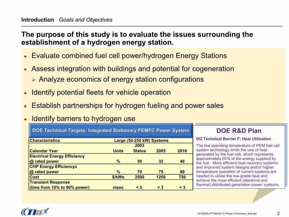
The purpose of this study is to evaluate the issues surrounding the establishment of a hydrogen energy station.
• Evaluate combined fuel cell power/hydrogen Energy Stations
• Assess integration with buildings and potential for cogenerationAnalyze economics of energy station configurations
• Identify potential fleets for vehicle operation
• Establish partnerships for hydrogen fueling and power sales
• Identify barriers to hydrogen use
Characteristics Large (50-250 kW) Systems
Calendar Year Units2003
Status 2005 2010Electrical Energy Efficiency@ rated power % 30 32 40CHP Energy Efficiencyc@ rated power % 70 75 80Cost $/kWe 2500 1250 750Transient Response(time from 10% to 90% power) msec < 3 < 3 < 3
DOE Technical Targets: Integrated Stationary PEMFC Power SystemDOE Technical Targets: Integrated Stationary PEMFC Power System DOE R&D PlanDG Technical Barrier F: Heat Utilization. The low operating temperature of PEM fuel cell system technology limits the use of heat generated by the fuel cell, which represents approximately 50% of the energy supplied by the fuel. More efficient heat recovery systems and improved system designs and/or higher temperature operation of current systems are needed to utilize the low-grade heat and achieve the most efficient (electrical and thermal) distributed generation power systems.
DOE R&D PlanDG Technical Barrier F: Heat Utilization. The low operating temperature of PEM fuel cell system technology limits the use of heat generated by the fuel cell, which represents approximately 50% of the energy supplied by the fuel. More efficient heat recovery systems and improved system designs and/or higher temperature operation of current systems are needed to utilize the low-grade heat and achieve the most efficient (electrical and thermal) distributed generation power systems.

041003/SL/PT/D0035 FC Phase III Summary_draft.ppt 3
Introduction Hydrogen Energy Station Overview
The purpose of this study is to evaluate the issues surrounding the establishment of a hydrogen energy station
• Evaluate combined fuel cell power/hydrogen Energy Stations Analyze energy station systems with 50 kW PEMFCs that are suitable for installation in Federal buildingsAnalyze options for system components including direct hydrogen and reformate fuel cells and various storage, power production, and hydrogen usage configurationsDetermine costs and energy efficiency for different system configurations
• Assess integration with buildings and potential for cogenerationAnalyze potential for heat recovery from fuel cell/hydrogen production systemsIdentify potential for cogeneration in Federal building applications
• Identify potential fleets for vehicle operation
• Establish partnerships for hydrogen fueling and power sales
• Identify barriers to hydrogen use
• This study was supported by DOE contract DE-FC36-01GO11088
041003/SL/PT/D0035 FC Phase III Summary_draft.ppt 4
Introduction Tasks and Schedule
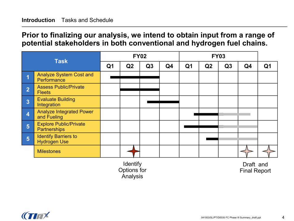
Prior to finalizing our analysis, we intend to obtain input from a range of potential stakeholders in both conventional and hydrogen fuel chains.
Task
1
2 Assess Public/Private Fleets
Analyze System Cost and Performance
Q1FY02 FY03
Q2 Q3 Q4 Q1 Q2 Q3 Q4 Q1
Evaluate Building Integration3Analyze Integrated Power and Fueling4Explore Public/Private Partnerships5Identify Barriers to Hydrogen Use5
Milestones
Identify Options for
Analysis
Draft and Final Report

041003/SL/PT/D0035 FC Phase III Summary_draft.ppt 5
Hydrogen Energy Station System Analysis Component Options
Several component choices are options for hydrogen production systems
Blower for SMR,Compressor for ATR,
C/E for ATR
Blower for SMR,Compressor for ATR,
C/E for ATR
50 kWeFuelCell
Reformer
Purif
icat
ion
Reformate FC,Direct H2 FC,
High pressure H2 FC
Reformate FC,Direct H2 FC,
High pressure H2 FCFC Coolant (heat)
Reformer exhaust (heat)PSA Tailgas (low Btu gas)
FC Coolant (heat)Reformer exhaust (heat)
PSA Tailgas (low Btu gas)
Cogen
Air HydrogenStorage
SMR (1 atm), SMR (10 atm), ATR (10 atm)
SMR (1 atm), SMR (10 atm), ATR (10 atm) PSA, Membrane,
Fluorinated HydridePSA, Membrane,
Fluorinated HydrideEliminate
compressor with 10 atm reformer
Eliminate compressor with 10 atm reformer
Natural Gas
Dispenser

041003/SL/PT/D0035 FC Phase III Summary_draft.ppt 6
Hydrogen Energy Station System Configurations
We applied filters to the matrix of possible configurations to select four promising technology combinations that meet various customer needs
Major ComponentsMajor ComponentsSystem AttributesSystem Attributes
Simple cogeneration
SMR, Reformate Fuel Cell, PSA
SMR, PSA, Direct Hydrogen Fuel Cell
SMR, Reformate Fuel Cell, Fluorinate metal hydrides
Air Compressor, ATR, PSA, Direct Hydrogen Fuel Cell
Small scale purification
Conventional system
Lower cost fuel cell
Note: Cost are for high production volumes: 1,000+ units per year.Variations in operating profile are also being considered

041003/SL/PT/D0035 FC Phase III Summary_draft.ppt 7
Hydrogen Energy Station System Analysis SMR Configuration
A steam reformer results in higher hydrogen yield and simpler purification.
BlowerBlower
Purif
icat
ion
Steam-Methane Reformer
Direct H2 FCDirect H2 FC
Reformate compressorReformate compressor
50 kWeFuelCell
FC Coolant (heat)Reformer exhaust (heat)
FC Coolant (heat)Reformer exhaust (heat)
Cogen
Air HydrogenStorage
Natural Gas
Dispenser
SMR (1 atm)SMR (1 atm)PSAPSA
An ideal system would include a high pressure reformer and eliminate the reformate compressor.
041003/SL/PT/D0035 FC Phase III Summary_draft.ppt 8
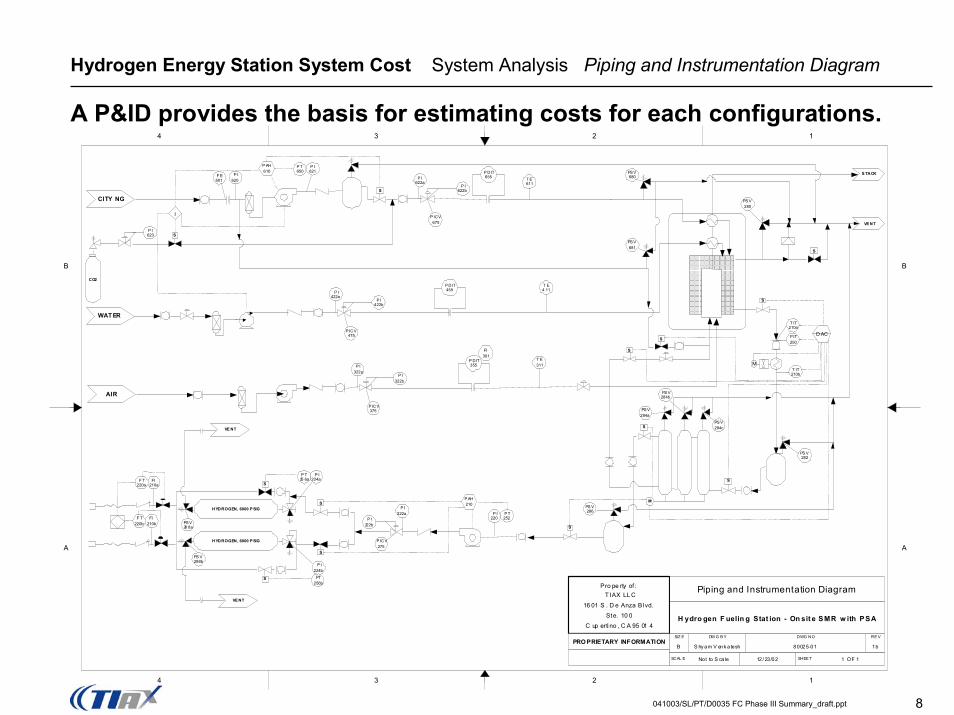
Hydrogen Energy Station System Cost System Analysis Piping and Instrumentation Diagram
A P&ID provides the basis for estimating costs for each configurations.
Pro pe rty of : T IAX LL C
16 01 S . D e Anza Bl vd.Ste. 10 0
C up erti no , C A 95 01 4
PRO PRIETARY INFORMATION
Piping and Instrumentation Diagram
H ydro gen F uelin g Stat ion - On sit e SMR w ith PSA
SIZ E DW G B Y DWG NO RE V
B S hy am V enk a tesh 80025-01 1b
SCAL E Not to S ca le 12 / 23/02 SHEE T 1 OF 1
CITY NG
AIR
WAT ER
CO2
HYDROGEN, 6000 P SIG
HYDROGEN, 6000 P SIG
S
S
S
S
S
S TACK
VE NT
M
S
F E601
P I620
P I621
P T650
P AH610 P DIT
655 T E611
I
P I622b
P I622a
P ICV675
S
PS V680
PS V681
PS V280
PS V284a
PS V284b
PS V284c
T IT210a
P IT250
D AC
T IT210b
P I220
P T252
S
P I222b
P I222a
P ICV275
P AH210
P I224a
P T25 6a
P I224b
PT256b
PS V288b
PS V28 8a
FI210a
F T220a
FI210b
F T220b
P DIT455
P I422b
P I422a
P ICV475
P DIT355
P ICV375
S
S
S
S
PS V282
PS V286
VE NT
P I322a
P I322b
FI301
T E311
T E4 11
M
P I623
S
B
A
4 3 2 1
B
A
4 3 2 1
VE NT

041003/SL/PT/D0035 FC Phase III Summary_draft.ppt 9
Hydrogen Energy Station System Analysis Operational Profiles
Daily operational levels for the FC and reformer will vary depending upon the target energy utilization strategy for the energy station si
X-Axis
BuildingLoad
Fuel ProcessorSized for Average
Loads Time
Fuel Cell StackOperated to Offset
Peak Loads AverageLoad
Power Demand and Related Fuel Cell Operational Scenarios
0 1 2 3 4 5 6 7 8 9 10 11 12 13 14 15 16 17 18 19 20 21 22 23 24
Time of day
Pow
er D
eman
d
Station and building loadVehicle load
Load-following FC outputConstant reformer load
Hydrogen from reformer into FC
Excess hydrogen into Storage
Hydrogen from Storage into FC
Power Demand and Fuel Cell Operating StrategiesPower Demand and Fuel Cell Operating Strategies
te
♦ Base-loaded
♦ Electric load-following
♦ Heat-load following co-generation
♦ Peak shaving
♦ Back-up power
♦ Tailgas Exhaust to Boiler
Candidate Operating StrategiesCandidate Operating Strategies
Matching Building loads:Peak shaving: operating the fuel cell to reduce peak load on utility serviceAverage load: operate the reformer and fuel cell continuously to provide power to building Emergency backup: operate fuel cell on stored hydrogen and/or reformer during power emergencies

041003/SL/PT/D0035 FC Phase III Summary_draft.ppt 10
Hydrogen Energy Station System Cost Economic Analysis Cost Curves
In addition to technical performance parameters, the cost of components depends on production volumes.
$-
$100
$200
$300
$400
1,000 10,000 100,000 1,000,000Production Volume, units/year
Stac
k Fa
ctor
y C
ost,
$/kW
H2 PEMFC 450 mW/cm2
SR PEMFC 430 mW/cm2
Example 5kW system0.6 mg/cm2 Pt total
Example
PEMFC stack components will be used in both vehicle and stationary applications while markets for steam reformers will be more limited.

041003/SL/PT/D0035 FC Phase III Summary_draft.ppt 11
Hydrogen Energy Station Economics Production Volume Effects
The commercial success of any FCV, regardless of fuel, is tied to the cost of the fuel cell engine. Other fuel cell markets can help bring down costs.
10
100
1,000
10,000
2000 2005 2010 2015 2020
Stac
k C
ost (
$/kW
)
50,000 FCVs/yr
500,000 FCVs/yr and>100,000 stationary FCs
Gradual Vehicle Introduction
Fuel Cells in Multiple Markets
♦ Demonstration vehicles♦ Government fleets♦ Premium power♦ Combined heat and power♦ Commercial vehicle sales
♦ Demonstration vehicles♦ Government fleets♦ Premium power♦ Combined heat and power♦ Commercial vehicle sales

041003/SL/PT/D0035 FC Phase III Summary_draft.ppt 12
Hydrogen Energy Station Efficiency and Economics Fuel Cell System Architecture Options
There are two basic fuel cell architectures with multiple variations thereof
CO Cleanup
Fuel Processing
Fuel Cell Stack
Fuel
H2, CO2, CO,N2, H2O
“Conventional” -- Integrated Reformate Fueled PEMFC
Fuel ProcessorSubsystem
Fuel Cell Stack (~40% size reduction with H2 feed)
Fuel
Separate H2 Production & Purification Pure H2 Stack
H2Purification
CO2, CO,N2, H2O
H2 Storage
(1)
H2
This system strategy allows use of PEMFC stack technology that is likely to be available, and affordable due to early vehicle demos.

041003/SL/PT/D0035 FC Phase III Summary_draft.ppt 13
Hydrogen Energy Station System Analysis Fueling Capacity
Several trade-off options available between generating FC electricity and providing sufficient hydrogen for vehicle fueling
Fuel Cell Demand and Number of Vehicles Servedby a 50 kWe Reformer
0
10
20
30
40
50
60
70
0 200 400 600 800 1000 1200 1400Daily Fuel Cell Power (kWhe DC)
Max
imum
Use
able
Hyd
roge
n fro
m
Ref
orm
er O
utpu
t (kg
/day
)
50kWeReformer,Full LoadOperation
2 car fill-up
4 car fill-up
6 car fill-up
8 car fill-up10 car fill-up
12 car fill-up
Constraints on Vehicle Fueling and Fuel Cell Power Constraints on Vehicle Fueling and Fuel Cell Power Output Output -- 50 50 kWkWee ReformerReformer
Operating Strategies: Back up Peak Shaving Base Load
The reformer capacity, vehicle refuelings, and fuel cell can be matched for different operating strategies

041003/SL/PT/D0035 FC Phase III Summary_draft.ppt 14
Hydrogen Energy Station System Analysis Cogeneration Configuration
A simple cogeneration system uses the waste gas from an ATR to produce heat. Recovering the waste heat is simplified.
Purif
icat
ion
Auto-thermal Reformer
50 kWeFuelCell
Direct H2 FCDirect H2 FC
Eliminate reformate
compressor with 10 atm ATR
Eliminate reformate
compressor with 10 atm ATR
FC Coolant (heat), PSA Tailgas (low Btu gas)
FC Coolant (heat), PSA Tailgas (low Btu gas)
Air CompressorAir Compressor
Cogeneration
Air HydrogenStorage
Natural Gas
Dispenser
ATR (10 atm)ATR (10 atm)PSAPSA

041003/SL/PT/D0035 FC Phase III Summary_draft.ppt 15
Hydrogen Energy Station Technical Barriers Recognizing Environmental Benefits
With an energy station, optimal use of natural resources could be combined with zero emissions and extremely high reliability.
Over 90% reduction of criteria pollutant emissions
Enhances grid reliability through energy storage and fuel cells with few moving parts
Reduced greenhouse gas emissions
Managed technical risk through use of hydrogen fuel cells rather than conventional stationary fuel cell systems
Facilitates implementation of fueling infrastructure
Lower cost through shared components for vehicle fueling and stationary fuel cell power
Annual Greenhouse Gas Emissions
0100200300400500600700
Gasoline Vehicle, Grid Power Energy Station
GH
G E
mis
sion
s, to
n/yr
VehicleHeatPowerPower/Heat
Over 50 % Reduction
Annual Criteria Pollutant Emissions
020406080
100120140160180
Gasoline Vehicle, Grid Power Energy Station
Crit
eria
Pol
luta
nt
Emis
sion
s, k
g/yr Vehicle
HeatPowerPower/Heat
Over 95% Reduction
Note: criteria pollutants include NOx, CO, and hydrocarbons

041003/SL/PT/D0035 FC Phase III Summary_draft.ppt 16
Hydrogen Energy Station Proposed Future Work
Future energy stations need to evolve along with the vehicles.
Future WorkFuture Work
Compare cost and performance to baseline technologies
• Cost depends on vehicle and stationary FC production volume
ChallengesChallenges
Develop a design concept for larger scale production
• Much smaller packaging would facilitate acceptance in more locations
• Required stand off distances for hydrogen storage can be over 50 ft
Identify partners for commercialization • Need to obtain better perspective of benefits to federal fleets
• Strained economy limits new ventures• Code requirements are evolving• Deployment of hydrogen FCVs from manufacturers
presents a chicken/egg problem to potential energy station users
Evaluate barriers to hydrogen utilization

041003/SL/PT/D0035 FC Phase III Summary_draft.ppt 17
Hydrogen Energy Station Cooperative Efforts
A number of stakeholders are being contacted to determine their requirements and interest in energy stations.
StakeholdersStakeholders
AutomakersFuel cell manufacturerElectric utilitiesGovernment hospitalsMilitary basesGovernment fleetsEPACT fleets
Attend Fuel Cell Seminar Nov ‘02Made presentations on environmental impacts to CA Air Resources Board, South Coast AQMD, Blue Water Network, and othersSubmitted Paper to Dec ‘03 Fuel Cell Seminar
Outreach EffortsOutreach Efforts CommentsComments
“This (energy station) is the only way fuel cell infrastructure will ever work”
“Aren’t SOFCs more efficient for stationary applications?”
“We have to deal with Rule 21, for grid interconnection.”
“With the downturn in the economy we have to focus on our core activities.”
“If we could get a fuel cell car, this (energy station) would be a good idea.”