hydro mobile m2 series owner's manual v 5
TRANSCRIPT

Call us for information:1-888-484-9376 (US)
(toll free in the United States)450 589-8100 (Canada)
Owner’s Manual
11053005-0-00000-0
M2_OpMan_v5.02_EN

www.hydro-mobile.comGENERAL INFORMATION
Model M2 Series 14' (4,3 m) motorized unit
M2 Series 24' (7,3 m) motorized unit
Motorized unit serial number
Manufacturing date
© 2015 by Hydro Mobile Inc. All rights reservedThis manual was produced by Hydro Mobile Inc. on Adobe® InDesign CS5.5® version 5.0.1 for Windows®.Technical drawings were prepared using Autodesk Inventor ® 2012. Illustrations were created with Autodesk® 3ds Max®, Autodesk Inventor ® 2008, Adobe® Illustrator CS5.1 for Windows® and Adobe® Photoshop CS5.1® for Windows®.This manual may not, in whole or in part, be copied, photocopied, reproduced, translated, or converted to any electronic or machine readable form without prior written consent of Hydro Mobile Inc.APAVE certifi cation: 0077-5237-760-0411-4103 (2014)
125 de l’IndustrieL’Assomption, Quebec, Canada
J5W 2T9
NOTE
All assembly and operation instructions located on motorized units and bridges take precedence over information contained in this manual. Should there be any discrepancies discovered throughout any published documentation issued by Hydro Mobile or its authorized affi liates, the following order of precedence shall prevail:1. Written documents issued by the Hydro Mobile Engineering department2. Recall instructions3. Assembly or operation instructions displayed on the motorized unit4. Owner's manualAny use of one or several Hydro Mobile motorized units, with or without accessories, in such a confi guration or manner as not explicitly described in this manual is not allowed without the permission of Hydro Mobile Inc.
LEGEND OF ICONS
These icons are used to highlight important information throughout this manual
InformationUseful information for safe and easy operation
Warning noteAn important warning: damage or injury may occur
Useful tipA useful tip to facilitate installation or operation
Wind speed warningAn important warning: wind speed conditions must be observed to avoid damage or injury
Type of setupSingle unit freestanding installation
Type of setupSingle unit installation with mast ties
Type of setupMultiple units freestanding installation
Type of setupMultiple units installation with mast ties
The information and instructions contained in this manual applies to units bearing the following serial numbers
24M 5157 M2 and up 14M 0200 M2 and up
REVISION LISTVersion Date Descriptionv1.0 April 2002 First edition of Owner’s manual
v2.0 May 2002 Addition of forward extension and monorail
v2.1 June 2002 “Long” mast ties changed for “extensions”
v2.2 Sept 2002 Access and rest platforms
v3.0 Sept 2004 Addition of 14' (4,3 m) unit, split base and training sheets
v3.1 Sept 2004 Modifi cations to weights; various typographical corrections; modifi cation of grease type
v4.0 Sept 2010 Overall revision; inclusion of additional accessories; detailed warranty policy; inclusion of new modular bridge assemblies
v4.01 Oct 2010 Minor corrections
v4.02 Nov 2010 Modifi cations to load capacity charts; minor additions and corrections
v4.03 Oct 2015 Corrections to components included with shipped unit
v5.0 Feb/Mar 2016 Overall revision; major changes to installation instructions; inclusion of accessories (sidewalk canopy, mast base plates, swivel bridge, fl ush bearing bridge adapter, multiple mast handler) (typo corrections in March before fi rst print)
v5.01 Sept 2016 Modifi cation to distance to wall in MU dimensions; modifi cation of number of plywoods required when cribbing; modifi cations to bridge lengths in load capacities
v5.02 April 2017 Minor corrections; addition of storage instructions for unit and bridge
For orders or information:1-888-484-9376 (US)
(toll free in the United States)450 589-8100 (Canada)
11053005-0-00000-0

GENERAL INFORMATION
TABLE OF CONTENTS
Introduction .................................................................3Warranty .................................................................4
Performance and safety rules......................................5 Defi nition of the competent person ...................5 Defi nition of the qualifi ed person ......................5 General guidelines ............................................5 Defi nition of standard installation ......................7
Overview .................................................................8List of components included with shipped unit ............8Specifi cations ............................................................10Weight of components ...............................................12Dimensions 13Positioning Minimum bearing surface capacities ..............15 Cribbing ..........................................................16Setup and confi gurations General guidelines ..........................................17 Combination of standard and non standard confi gurations .................................................17 Defi nition of a standard confi guration .............17 Positioning of base outriggers ........................19 Installation of freestanding setups Single unit ...................................................19 Multiple units ...............................................21 Installation of tied setups Methods to install tie levels .........................22 “A” – progressive installation Single unit ..............................................23 Multiples units ........................................24 “B” – pre-installation of tie levels Single unit ..............................................25 Multiple units ..........................................27 “C” – pre-installation of tie levels Single unit ..............................................28 Multiple units ..........................................30 Dismantling an installation Safety guidelines .........................................32 Freestanding installations Single unit .............................................32 Multiple units ..........................................32 Tied installations Single unit (“A” or “B” installation) ................33 Multiple units (“A” or “B” installation) ............34 Single unit (“C” installation) ........................35 Multiple units (“C” installation).....................36 Lifting and moving a motorized unit setup ........37
Safety hooks system .................................................41Fall protection equipment ..........................................41
Standard bridge Overview .........................................................43Bridge types...............................................................43Cantilever bridge Installation.......................................................43Bearing bridge Safety guidelines ............................................46 Installation.......................................................46 Offset bearing bridge structure ...................47 Safety chains ..............................................47 Dismantling a bearing bridge ..........................48Multi purpose insert bridge (MPI) Forward/Back extension bridge ......................49 Cantilever bridge.............................................50 Lateral cantilever bridge .................................50 Narrow bearing bridge ....................................51Alternate bridge confi gurations ..................................53 Angled bearing bridge setup ...........................53 Inside / Outside corner bearing bridge............54Swivel bridge Installation of the square bridge adapter ........56 Installation of the swivel and square bridges ..57 Angle adjustment ............................................57 Standard and swivel bridge guardrails............58 Front cantilever confi gurations........................59 Counterweight adapter ...................................60
Motorized unit preparation instructions......................62Engine startup preparation instructions .....................63Storage of the control post ........................................64Raising the platform...................................................65Lowering the platform ................................................67
Installation of a mast section .....................................69Installation of mast ties ..............................................70 Mast tie schedule ............................................70 Appropriate mast tie installation......................71 Mast tie requirements for planking confi gurations ...................................72 Angle of mast ties and wall tie distances ........74 Passing mast tie levels ...................................75 Removal of mast ties ......................................75 Removal and transport of mast sections ........75 Angled mast ties .............................................76 Installation of the angle bracket ..................76 Installation of extended mast ties ................77Anchoring system Wall tie types ..................................................78 Installation of fl oor ties ....................................79 Installation of fi xed wall ties ............................79 Installation of a welded wall tie on a beam .......79 Installation of a re-usable wall tie....................79
Changes to the calculation method ...........................80Load capacity calculation guidelines .........................80Evenly distributed – Single unit setup 14' (4,3 m) motorized unit ...............................81 24' (7,3 m) motorized unit ...............................81Evenly distributed – Multiple units setup 14' (4,3 m) motorized unit ...............................82 24' (7,3 m) motorized unit ...............................83MPI – Evenly distributed with 24' (7,3 m) unit Lateral cantilever ............................................84 Forward extension ..........................................85 Narrow bearing bridge ....................................86Swivel bridge with 24' (7,3 m) unit Single unit front 0-45 degrees.........................87 Single unit with counterweight adapter ...........88Angled and corner installations Inside corner ...................................................89 Outside corner ................................................90
Safety accessories Guardrails Standard .....................................................91 Face guardrail supports ..............................91 Plank-end guardrails ...................................92 Movable guardrails ......................................93 Universal plank safety support ....................93 Retractable rest platform .............................94Other accessories Outriggers ........................................................... Planking confi guration guidelines ...............95 Outrigger selection table .............................95 Doubled outriggers ......................................96 Cross boxes ................................................97 Non standard planking confi gurations .........97 Top outriggers .............................................99 Bottom outriggers ........................................99 Cantilever outrigger supports ....................100 Sliding doors .................................................100 Wheel set ......................................................102 Hoist .............................................................103 Weather protection .......................................104 Monorail ........................................................108 Flush bearing bridge adapter ........................ 110 Securing the access walkway ....................... 111 Adapter base for sidewalk canopy installation ..................................................... 112 Mast base plates........................................... 115 Multiple mast handler.................................... 117
Transport and storage Preparation of the motorized unit for transport........................................................ 118 Storage of the control post............................ 119 Storage of the motorized unit........................ 119Inspections and maintenance Daily and weekly inspections and maintenance Inspection and maintenance of the cylinder hook .......................................120 Greasing the mast carriage and guide rollers ........................................................121 Inspecting and greasing the safety hooks ..............................................122 Frequent inspections and maintenance ........123 Annual inspections and maintenance ...........123 Examples of checklists .................................124 Hydraulic diagram .........................................125
General InformationGeneral Information
Performance and SafetyPerformance and Safety
1 – Motorized Unit1 – Motorized Unit
3 – Bridges3 – Bridges
4 – Power Pack and Operating Components4 – Power Pack and Operating Components
6 – Load Capacities6 – Load Capacities
7 – Accessories7 – Accessories
2 – Safety Devices2 – Safety Devices
8 – Transport, Storage and Maintenance8 – Transport, Storage and Maintenance
5 – Masts and Mast Ties5 – Masts and Mast Ties

GENERAL INFORMATION
Dear owner or user:
Thank you for investing in a Hydro Mobile M2 Series mast climbing work platform system (24' / 7,3 m model or 14' / 4,3 m model). The design of these motorized units refl ects over a decade of continued fi eld operation, testing and research work and comes as a solution to our company’s deepest concern, your safety and well being on the job.
To ensure that the workplace becomes safer and more effi cient using a Hydro Mobile system, always have appropriately trained personnel assemble, operate, dismantle and move your mast climbing work platform system. These qualifi ed persons will be required to read this owner’s manual and assimilate the information contained herein. Failure to do so could lead to serious injury and/or equipment damage.
These motorized units were designed in accordance with the following standards: US ANSI A92.9-2011, ISO 16369:2007 and EN 1495, 2006/42/CE “directive machine” and 89/336/CEE “directive CEM”. Furthermore, these motorized units and the owner’s manual comply with US ANSI A92.9-2011 standards, Federal Occupational Safety and Health Administration Standards OSHA 29CFR1926 subpart L; with ISO 16369:2007 and CSA B354.5-07; and with EN 1495, 2006/42/CE“directive machine”, 89/336/CEE “directive CEM” and ISO 16369:2007.
To maximize the life expectancy of your equipment and to enjoy years of trouble free operation, we recommend that this Hydro Mobile system be serviced according to maintenance schedules and recommendations provided in this manual. It is also advised to refer to the Honda user’s manual included with the motorized unit.
Should you have any questions or concerns, please contact the nearest authorized service center or Hydro Mobile directly at 888-484-9376 (in the United States) or 450 589-8100 (in Canada). You can also visit our Web site at www.hydro-mobile.com for additional support and information on our factory safety and performance training seminars.
We wish you years and years of safe, productive construction and renovation work.
Sincerely,
Introduction
Vincent DequoyPresident

GENERAL INFORMATION
Warranty
Warranty periodHydro Mobile Inc., herein referred to as Hydro Mobile, warrants its new M2 Series motorized units to be free from defect of materials and workmanship for a period of 15 months from the date of delivery to the authorized distributor/service center.Hydro Mobile also warrants its new M2 Series parts and accessories to be free from defect of materials and workmanship for a period of 15 months from the date of delivery to the authorized distributor/service center.
Description of warranty
Hydro Mobile's obligation and liability under this warranty are expressly limited to repairing or replacing with re-manufactured or new parts, at Hydro Mobile's option, any part and accessory manufactured by Hydro Mobile proven defective after inspection by Hydro Mobile which appear to have been defective in material or workmanship. Only permanent repairs will be covered under this warranty. Hydro Mobile reserves the right to ask for maintenance records of the defective part before settling a claim and to deny such claim if maintenance records are not available or not compliant with maintenance schedules. This warranty shall not apply to component parts or accessories of products not manufactured by Hydro Mobile and which carry the warranty of the manufacturer thereof or to normal maintenance (such as engine tune-up) or any part necessary to perform such maintenance. Hydro Mobile offers no other warranty, expressed or implied, and offers no warranty of merchantability or fi tness for any particular purpose.
Parts and accessories manufactured by Hydro Mobile
All engines manufactured by Honda under the "GX" lineup are covered by an international warranty of 36 months (12 months on muffl ers). To have an engine repaired under this warranty, the engine must be brought to an authorized Hydro Mobile distributor/service center or to a Honda authorized distributor/service center.
Engine
All the batteries shipped from the factory with new equipment are guaranteed for a period of 60 days. Any battery discharged due to operator error will not be covered under this warranty. Dead batteries that can be recharged will not be replaced under this warranty.
Battery
Hydro Mobile's obligation under such warranty shall not include duty, taxes or any other charge whatsoever, or any liability for direct, indirect, incidental or consequential damage or delay.
Costs and liability associated with warranty
Any use of one or several Hydro Mobile motorized units, with or without accessories, in such a confi guration or manner as not explicitly described in the owner's manual is not recommended without the prior written permission of Hydro Mobile.Any improper use, including operation after discovery of defective or worn parts, shall void this warranty. Improper use also includes operation beyond rated capacity, substitution of parts other than those approved by Hydro Mobile, including anchor systems, or any alteration, modifi cation or repair by others in such manner as in Hydro Mobile's judgment affects the product materially and adversely.
Exclusion
All warranty work must be performed by a certifi ed Hydro Mobile technician to be eligible for reimbursement under the warranty.
Labor
Product registrationIn accordance with standards governing mast climbing work platform systems, the owner of a Hydro Mobile M2 Series unit must register the product with Hydro Mobile within sixty (60) days. The initial buyer of a Hydro Mobile M2 Series unit is automatically registered by Hydro Mobile.
Hydro Mobile must be kept informed of any change of ownership. The new owner must provide Hydro Mobile with a full name and address, along with the model and serial number of the unit acquired.

5
PERFORMANCE AND SAFETY
Performance and Safety RulesSAFETY comes fi rst. The installation and operation of a mast climber is subject to hazards that can be avoided only by using extreme care and common sense, and by providing the appropriate training and supervision to all its users. It is essential that the installation and dismantling of an M2 Series motorized unit and its related accessories be carried out according to the guidelines, instructions and warnings included in the owner's manual and performed by qualifi ed erectors/dismantlers under the supervision of a competent person (see boxes below). It is also imperative that the operation of an M2 Series motorized unit setup be carried out according to the guidelines, instructions and warnings included in the owner's manual. To ensure safe and proper operation, Hydro Mobile recommends that two persons be on hand to perform maneuvers for each motorized unit in a setup and that at least one of those two persons is a qualifi ed operator (see box below) for an M2 Series motorized unit and its accessories.
General guidelines1- Prepare a layout plan showing how the mast climbing work platform system (motorized units, bridges and accessories) will be positioned near structures or walls to be erected. On long walls, install separate mast climber sections to allow for fl exibility. Make sure to position motorized units so as to provide proper anchoring points for masts for tied installations. 2- Rely on a licensed engineer for help on special jobs and to approve plans if required by local regulation. 3- It is recommended to use the job survey form as a guide for the proper installation of the confi guration. Refer to p. 124 of the Transport, Storage and Maintenance section for more information about the job survey form.
WARNINGIt is mandatory to refer to the Mast Tie Schedule table on p. 70 of the Masts and Mast Ties
section before the installation of any M2 Series confi guration.
WARNINGThe confi gurations and methods to achieve these confi gurations for an M2 Series installation shown and described in this owner’s manual are the only ones authorized by Hydro Mobile. For any confi guration or method to achieve such a confi guration other than those shown and described in this owner’s manual, contact the Hydro Mobile technical support team.
Defi nition of the competent person Competent person means a person who is capable of identifying existing and predictable hazards in the surroundings or working conditions which are unsanitary, hazardous or dangerous to employees,
and who has authorization to take prompt corrective measures to eliminate them.
Defi nition of the qualifi ed person“Qualifi ed” means a person who, by possession of a recognized degree, certifi cate or professional standing, or who by extensive knowledge, training and experience, has successfully demonstrated the ability to solve or resolve problems relating to the subject matter, the work or the project.Only a qualifi ed person on the specifi c make and model of the Hydro Mobile equipment can carry out the following tasks:User/operatorA qualifi ed user/operator is allowed to operate Hydro Mobile units according to the guidelines, instructions, warnings and methods set out in the owner’s manuals and Hydro Mobile training courses and after they have been erected, tested and passed for use by a qualifi ed person. Erector/dismantlerA qualifi ed erector/dismantler is allowed to erect, dismantle, test, pass for use and modify the confi guration of Hydro Mobile units according to the guidelines, instructions, warnings and methods set out in the owner’s manuals and Hydro Mobile training courses. TechnicianA qualifi ed technician is allowed to perform maintenance inspections and repairs on Hydro Mobile units according to the guidelines, instructions, warnings and methods set out in the owner’s manuals and Hydro Mobile training courses.
Hydro Mobile recommends that Qualifi ed Persons follow the Hydro Mobile University Training Program on the specifi c task and specifi c make and model to get proper qualifi cations. For more
information on the Hydro Mobile University Training Program, visit www.hydro-mobile.com/training.

6
PERFORMANCE AND SAFETY
Performance and Safety Rules
4- Any M2 Series setup requiring an approved, angled or non-linear confi guration achieved with a forward/back extension or a swivel bridge must have mast ties. In addition, mast ties must be installed following the appropriate schedule for the installation of tie levels. 5- Any M2 Series setup requiring the use of additional, approved accessories and equipment such as a hoist and hoist support structure specifi cally manufactured to be used on an M2 Series installation, weather protection or an approved planking confi guration wider than the standard four planks must have mast ties. In addition, mast ties must be installed following the appropriate schedule for the installation of tie levels.6- It is mandatory to refer to the Mast Tie Schedule table on p. 70 of the Masts and Mast Ties section and to the Load Capacities section on p. 80 before the installation of any M2 Series confi guration. 7- Establish the distance between the mast climbing work platform system and the structure or wall, taking into account the length of plank outriggers, as well as curvatures, balconies, columns, trees, telephone wires, electrical lines, etc. 8- Refer to and follow local regulations governing distances between the mast climbing work platform system and electrical lines. As a reference, North American regulations generally recommend keeping a safe distance of at least 10' (3 m) from overhead power lines carrying 50,000 volts or less. 9- Make sure the ground or support surface capacity meets with values included in the Minimum Bearing Surface Capacities table herein (fig. 1.18, p. 15). Soil compacting, cribbing or shoring can increase bearing capacity. 10- Never modify the mast climbing work platform system or use substitute factory parts. This could adversely affect worker safety, unit performance and void the warranty. In addition, this could lead to serious injury or death. 11- The M2 Series motorized unit must not be used with any equipment or any accessories not specifically manufactured and rated by Hydro Mobile to be used with M2 Series motorized units. For the use and installation of any such equipment or accessories, contact the distributor/service center or the Hydro Mobile technical support team. 12- Never use the motorized unit in a enclosed space due to carbon monoxide emissions or in a place where explosives are stored. It is recommended to use an electrically-powered motorized unit as an alternative.13- Each M2 Series motorized unit must be equipped with an appropriate fi re extinguisher (not supplied). Use the bracket supplied with the motorized unit to hang the fire extinguisher in a readily accessible location (fi g. 1.1, p. 8).14- It is recommended not to smoke on the platform.15- Planks used for planking must be scaffold graded (SPF), in good condition and meet local regulations. 16- IMPORTANT: It is strongly recommended not to use equipment that may generate excessive vibrations or reactions on Hydro Mobile platforms.17- Workers exposed to potential hazards must always wear proper personal protection equipment (PPE) such as a helmet, safety boots, a fall arrest harness, etc., as prescribed by local regulations. In all cases where workers are exposed to fall hazards, fall protection is required. Installation of all the necessary guardrails is mandatory.18- The M2 Series motorized unit must only be used on a mast whose height does not exceed 250' (76 m). 19- To ensure work effi ciency, maintain an adequate equipment and parts inventory on the job site. Keep equipment in good condition. 20- Inspection and maintenance operations must be carried out effi ciently and in a timely manner. Daily inspections and their related operations must be performed by a qualifi ed user/operator every day or before every working shift. Frequent and annual inspections and their related operations must be carried out by a qualifi ed technician. Refer to the Transport, Storage and Maintenance section on p. 120 for more information on inspection and maintenance requirements for M2 Series motorized units and their accessories. 21- After installation, mark off limit areas of the system using fencing, barriers, warning tape and note emergency phone numbers (fi re and police dept.) for quick reference. Prepare an emergency evacuation plan that is specifi c to the job site and is in accordance with local regulations. 22- Never load bridges or motorized units beyond their rated capacities. Overloading may bring damages to equipment or cause the installation to become unbalanced, leading to serious injury or death.
General guidelines (cont’d)

7
PERFORMANCE AND SAFETY
23- Contact the distributor/service center or Hydro Mobile for service, repair or technical advice. Refer to equipment type and serial number when calling. 24- Each person should access the platform by a staircase, through an opening in the building or, when the unit is at least 10' (3 m) above base level, by the back of the mast, using the access walkway to reach the platform. The use of the access walkway is mandatory to reach the platform by the mast. To avoid crushing hazards, it is important to make sure that the access ladder is fully extended before it is used. In all cases, transfer must be safe and free from obstruction.25- The use of appropriate fall protection equipment is mandatory when using the mast for climbing or descending at heights between 30' (9,1 m) and 69' (21 m), when modifying plank confi guration or whenever the worker is exposed to a fall hazard. Failure to use fall protection equipment can expose the user to serious injury or death. It is not recommended to climb up the mast to reach work areas at heights over 69' (21 m) because of the time and effort required to reach such heights. The use of alternate equipment compliant with local regulations, such as a rapid mast climber, a transport platform system, or a conventional scaffold stair system will prove to be more effi cient. Refer to local regulations for more information. 26- Only one person at a time may evacuate the platform by climbing down the mast. It is not recommended to evacuate the platform by climbing down the mast when the platform is at heights beyond 69' (21 m).27- In the event of an abnormal occurrence or operation which could compromise security (ex. malfunction of a motorized unit component, collision with an obstacle, etc.), immobilize the unit and inform the competent person.28- It is strongly recommended not to touch any of the moving parts on the motorized unit when it is in use. 29- All access doors and panels on the motorized unit must be closed when they are not in use. All access doors and panels should be free from any material or obstruction. 30- The motorized unit must not be used or operated during an electrical thunderstorm. 31- The deposit of loads on the setup must be done with extreme care and under proper supervision. Refer to the Load Capacities section on p. 80 for more information about placing loads on the platform. When the motorized unit setup is not in use and above base level, loads must not be left on the platform except for counterweights.
Performance and Safety RulesGeneral guidelines (cont’d)
Defi nition of a standard installation A standard installation, referred to throughout this owner’s manual and related documentation, is an installation that does not require the use of additional equipment, such as a forward extension bridge, a swivel bridge or a planking confi guration wider than four planks nor the use of accessories such as
weather protection, a hoist or a monorail.It is mandatory to refer to the Load Capacities section on p. 80 for the number of bridges allowed in
a standard single unit or multiple units installation.
WARNING - WIND SPEEDS The erection and dismantling of a motorized unit setup (including the base, the bridges, the masts, the mast ties and all the other components) must not be conducted when wind speeds exceed 28 mph (45 km/h). Freestanding installations and setups equipped with weather protection, when allowed, must not be used with wind speeds exceeding 28 mph (45 km/h). Weather protection, when allowed, must not be used when work is performed on an open air structure. A motorized unit setup with mast ties must not be operated when wind speeds exceed 35 mph (56 km/h). When a motorized unit is not in use- It is mandatory to leave the platform between two tie levels when the motorized unit is not in use.- Remove all loads from the setup when the motorized unit is not in use. - It is mandatory to leave all the counterweights applied on the setup in place when the motorized unit is not in use. - In a freestanding installation, when allowed, the motorized unit must be brought down to base level when not in use.- If wind speeds are expected to exceed 94 mph (150 km/h), the motorized unit must be brought down to base level when not in use.

8
fi g. 1.1
fi g. 1.2
fi g. 1.3
1 - MOTORIZED UNIT
Motorized Unit Overview
Sliding door guardrails
84" (213 cm) door support
guardrail
84" (213 cm) end guardrail with pockets
72" (183 cm) outrigger
Access walkway Plank-end
guardrailsBottom mast section (welded
on base)
Adjustable jack
Mudsill
Base
Control post
24' (4,3 m) motorized unit structure
Access panel
HooksEngine
access panel
List of components included with shipped unitM2 SERIES 24' (7,3 m) MOTORIZED UNIT
Qty Component Qty Component1 M2 Series 24' (7,3 m) motorized unit 1 1 1/2" wrench
1 15/16" wrench 2 84" (213 cm) end guardrails
2 sliding guardrail doors 4 pockets for 84" (213 cm) end guardrails
2 84" (213 cm) guardrail doors 6 72" (183 cm) outriggers
2 plank-end guardrails 1 Owner’s manual
1 support for fi re extinguisher
M2 SERIES 14' (4,3 m) MOTORIZED UNITQty Component Qty Component1 M2 Series 14' (4,3 m) motorized unit 1 1 1/2" wrench
1 15/16" wrench 2 84" (213 cm) end guardrails
2 sliding guardrail doors 4 pockets for 84" (213 cm) end guardrails
2 44" (112 cm) guardrail doors 4 72" (183 cm) outriggers
2 plank-end guardrails 1 Owner’s manual
1 support for fi re extinguisher
NoteThe list of components included with each shipped motorized unit may change without notice.
24' (7,3 m) motorized unit
Mast tie door
Note: Items depicted in illustrations may differ from actual products.
Support for fi re extinguisher
Base outrigger
84" (213 cm) end guardrail with pockets
84" (213 cm) door support
guardrail

9
fi g. 1.4
fi g. 1.5
fi g. 1.6 fi g. 1.7
fi g. 1.8
1 - MOTORIZED UNIT
Motorized Unit Overview
Sliding guardrail doors44" (112 cm) door
support guardrail44" (112 cm) door support guardrail
72" (183 cm) outrigger
Adjustable jack
Mudsill
Base
Control post
14' (4,3 m) motorized unit structure
Access panel
Plank-end guardrails
Access walkway
Engine access
panelHooks
14' (4,3 m) motorized unit
Guardrail storage location
Forklift tubes(for transport)
Hydraulic tank
Engine
Power pack
Mast tie door
24' (7,3 m) motorized unit shown in this illustration
Bottom mast section (welded on
base)
Support for fi re extinguisher
Base outrigger
84" (213 cm) end guardrail with pockets
84" (213 cm) end guardrail with pockets

10
fi g. 1.9
fi g. 1.10
1 - MOTORIZED UNIT
Motorized Unit Specifi cations
fig 1 9
General Specifi cations
24' (7,3 m) model 14' (4,3 m) model
Dimensions of the motorized unit (as shipped)
84" x 288" x 48"(2,1 m x 7,3 m x 1,2 m)
84" x 168" x 48"(2,1 m x 4,3 m x 1,2 m)
Drive system Hydraulic ratchet drive Hydraulic ratchet drive
Maximum height 250' (76 m) 250' (76 m)
Distance between tie levels
Up to 30' (9,14 m) if mast ties are pre-installed(refer to Masts and Mast Ties section for complete information)
Up to 30' (9,14 m) if mast ties are pre-installed(refer to Masts and Mast Ties section for complete information)
Freestanding height 35' (10,1 m) with extended telescopic base outriggers
25' (7,6 m) with extended telescopic base outriggers
Safety devices Safety hooks Speed-activated hook system Safety hooks Speed-activated
hook system
fig 1 10
Specifi c Features
24' (7,3 m) model 14' (4,3 m) model
Platform weight(as shipped)
Total 7300 lb (3311 kg) 6000 lb (2722 kg)
Base 2300 lb (1043 kg) 1500 lb (680 kg)
MU structure assembly 5000 lb (2268 kg) 4500 lb (2041 kg)
Maximum load capacity
Single unit installation
16,600 lb at 64' (7530 kg at 19,7 m)
19,300 lb at 34' (8754 kg at 10,4 m)
Multiple units installation
30,000 lb at 148'(13 607 kg at 45,1 m)
32,800 lb at 108'(14 878 kg at 32,9 m)
Maximum lifting capacity 22,000 lb (9979 kg) 22,000 lb (9979 kg)
Vertical travel speed 3' (0,9 m) per minute 3' (0,9 m) per minute
Mast section16" x 16" x 60"(40,6 cm x 40,6 cm x 1,5 m)235 lb (107 kg) per section
16" x 16" x 60"(40,6 cm x 40,6 cm x 1,5 m)235 lb (107 kg) per section
Bridges Refer to the Bridges section for dimensions
Refer to the Bridges section for dimensions
Guardrails (included)Sliding guardrail doors (2)Plank-end guardrails (2)84" (213 cm) end guardrails (2)84" (213 cm) door support guardrails (2)
Sliding guardrail doors (2)Plank-end guardrails (2)84" (213 cm) end guardrails (2)44" (112 cm) door support guardrails (2)

11
fi g. 1.11
fi g. 1.12
fi g. 1.13
1 - MOTORIZED UNIT
Motorized Unit Specifi cations
fi g. 1.11
Hydraulic Specifi cations
Component Specifi cations
Double gear pump 2 x 3.18 GPM (2 x 12,02 l/min)
Hydraulic cylinder 2 x 3 1/2" x 23 1/2" x 1 1/2" (8,9 cm x 59,7 cm x 3,8 cm) with 3000 psi counterbalance
Hydraulic tank capacity 5.26 US gal (19,9 l)
Hydraulic oil Dexron III ATF
Oil fi lter Ikron fi lter model HE K44-20-135-AS-SP010(HM part number A0410000-0004)
fi g. 1.12
Engine Specifi cations
24' (7,3 m) model 14' (4,3 m) model
Model Honda GX270 Honda GX270
Rated power 9 HP @ 3600 RPM 9 HP @ 3600 RPM
Consumption 313 g / kWh (230 g / hph) 313 g / kWh (230 g / hph)
Spark plug BPR6ES BPR6ES
Oil type SAE 10W30 SAE 10W30
Gasoline tank capacity 1.6 US gal (6 l) 1.6 US gal (6 l)
Oil capacity 1.16 US qt (1,10 l) 1.16 US qt (1,10 l)
Electrical power supply 12 VDC – 10 Ah 12 VDC – 10 Ah
Battery 12 VC – 230 CCA 12 VC – 230 CCA
For any other information regarding the use and maintenance of Honda engines, refer to the Honda User’s manual.
1 measured at 23' (7 m) @ 3600 RPM2 with super silent muffl er, noise level is 76 dB(A) fig 1 131 measured at 23' (7 m) @ 3600 RPM
Operation Specifi cations
Wind exposure
Maximum wind speed allowed
During operation (of a setup with mast ties) 35 mph (56 km/h)
During erecting and dismantling (all types of setups), for freestanding installations and setups equipped with
weather protection28 mph (45 km/h)
When unit is not in use 94 mph (150 km/h)
A setup with mast ties should only be used on masts whose height does not exceed 250' (76 m).
For complete information about wind speed restrictions and recommendations, see warning on p. 7.
A freestanding setup should only be used on masts whose height does not exceed 35' (10,1 m) for 24' (7,3 m) motorized units and 25' (7,6 m) for 14' (4,3 m) motorized units, with extended telescopic base outriggers for both motorized unit models
Noise exposure
Standard noise level 1 = 83 dB(A) 2

12
fi g. 1.14
1 - MOTORIZED UNIT
Motorized Unit Specifi cations
fi 1 14
Weight of Components
Description Weight
24' (7,3 m) motorized unit 7300 lb (3311 kg)
14' (4,3 m) motorized unit 6000 lb (2722 kg)
24' (7,3 m) base assembly 2300 lb (1043 kg)
14' (4,3 m) base assembly 1500 lb (680 kg)
24' (7,3 m) structure assembly 5000 lb (2268 kg)
14' (4,3 m) structure assembly 4500 lb (2041 kg)
Mast assembly 235 lb (107 kg)
Walkway operator assembly 420 lb (191 kg)
6' (1,8 m) bearing bridge adapter assembly 900 lb (408 kg)
10' (3 m) modular bridge assembly 1360 lb (617 kg)
5' (1,5 m) modular bridge assembly 795 lb (361 kg)
Multi-purpose insert bridge assembly 800 lb (363 kg)
72" (183 cm) outrigger kit 25 lb (11 kg)
120" (305 cm) outrigger kit 55 lb (25 kg)
Sliding guardrail door - LEFT assembly for 24' (7,3 m) motorized unit 68 lb (31 kg)
Sliding guardrail door - RIGHT assembly for 24' (7,3 m) motorized unit 68 lb (31 kg)
Sliding guardrail door - LEFT assembly for 14' (4,3 m) motorized unit 50 lb (23 kg)
Sliding guardrail door - RIGHT assembly for 14' (4,3 m) motorized unit 50 lb (23 kg)
84" (213 cm) door support guardrail for 24' (7,3 m) motorized unit 70 lb (32 kg)
44" (112 cm) door support guardrail for 14' (4,3 m) motorized unit 50 lb (23 kg)
84" (213 cm) end guardrail 60 lb (27 kg)
60" (150 cm) guardrail 32 lb(15 kg)
Plank-end guardrail 30 lb (14 kg)
Movable guardrail assembly – TYPE 2 75 lb (34 kg)
Hoist main assembly 1860 lb (844 kg)
Hoist power pack rack assembly 750 lb (340 kg)
Hoist power pack bracket adapter for 14' (4,3 m) motorized unit 30 lb (15 kg)
Monorail beam assembly 85 lb (39 kg)
Junction plate assembly 19,5 lb (9,5 kg)
Monorail beam attachment assembly 27 lb (12 kg)
Weather protection – complete kit 224 lb (102 kg)
Weather protection connection tube kit 68 lb (31 kg)
Weather protection post assembly – TYPE 1 37 lb (17 kg)
Weather protection top outrigger kit 74 lb (34 kg)
Swivel bridge assembly (with guardrail) 800 lb (363 kg))
5' (1,5 m) square bridge assembly 390 lb (177 kg)
Flush bearing bridge adapter 350 lb (159 kg)
Wheel set 535 lb(243 kg)
Square bridge adapter assembly 230 lb (112 kg)

13
fi g. 1
.15
1 - MOTORIZED UNIT
Motorized Unit Specifi cations
Fron
t
Bac
k
Dimensions of the Motorized Unit
190
3/16
"48
3,1
cm
28 3
/8"
72,1
cm
105
1/4"
267,
3 cm
55 5
/8"
141,
3 cm
180
1/8"
457,
5 cm
196
3/16
"49
8,3
cm
202
3/16
"51
3,6
cm
288"
731,
5 cm
45 1
/4"
114,
9 cm
A
* 14
1 3/
8" (3
59,1
cm
) with
out
rigge
rs fu
lly e
xten
ded
24' (
7,3
m) m
otor
ized
uni
t
93 3
/8"
237,
2 cm
*
A =
Dis
tanc
e fr
om fi
nish
ed w
all.
For m
ore
info
rmat
ion,
re
fer t
o th
e ge
nera
l ins
talla
tion
guid
elin
es, o
n p.
18.
Ther
e m
ust b
e an
11"
(28
cm) c
lear
ance
bet
wee
n th
e fro
nt e
dge
of th
e m
otor
ized
uni
t dec
k an
d th
e fi n
ishe
d w
all

14
fi g. 1
.16
fi g. 1.17
1 - MOTORIZED UNIT
14' (
4,3
m) m
otor
ized
uni
t
Dimensions of the Motorized Unit
106
3/16
"27
1,5
cm
28 3
/8"
72,1
cm
Fron
t
Bac
k
105
1/4"
267,
3 cm
93 3
/8"
237,
2 cm
55 5
/8"
141,
3 cm
96 1
/8"
244,
2 cm
112
1/4"
285,
1 cm
118
3/16
"30
0,2
cm
168
1/4"
427,
4 cm
* 14
1 3/
8" (3
59,1
cm
) with
out
rigge
rs fu
lly e
xten
ded
45 1
/4"
114,
9 cm
A
*
Side view dimensions24' (7,3 m) motorized unit and 14' (4,3 m) motorized unit
54 1/4"137,8 cmFront Back47 1/2"
120,7 cm
30 5/16"77 cm
57 9/16"146,2 cm
87 7/8"223,2 cm
Ther
e m
ust b
e an
11”
(28
cm)
clea
ranc
e be
twee
n th
e fro
nt e
dge
of th
e m
otor
ized
uni
t dec
k an
d th
e fi n
ishe
d w
all
A =
Dis
tanc
e fr
om fi
nish
ed w
all.
For m
ore
info
rmat
ion,
re
fer t
o th
e ge
nera
l ins
talla
tion
guid
elin
es, o
n p.
18.

15
fi g. 1.18
fi g. 1.19
1 - MOTORIZED UNIT
Positioning the Motorized Unit
Mudsill
Jack
Cribbing may be required to distribute reaction depending
on the bearing surface
WARNINGMake sure the ground or support surface capacity meets with values
included in the Minimum Bearing Surface Capacities table (fi g. 1.18). Soil compacting, cribbing or shoring can increase bearing capacity. Contact an
engineer for assistance.
Minimum Bearing Surface Capacities
HeightMotorized unit
(pressure per mudsill) Load under mast
Mudsill: 14" x 28" (35,6 x 71 cm)Contact surface: 392 sq in (,25 m2)
(ft) (m) Load reactionLoad
pressure(psi)
Load pressure
(kpa)Load reaction
35 10,715 972 lb
41 28321 880 lb
7245 kg 9925 kg
50 15,215 005 lb
38 26222 735 lb
6806 kg 10 312 kg
75 22,915 830 lb
40 27623 985 lb
7180 kg 10 879 kg
100 30,516 655 lb
43 29625 235 lb
7556 kg 11 446 kg
150 45,718 305 lb
47 32427 735 lb
8303 kg 12 580 kg
200 61,019 955 lb
51 35230 235 lb
9051 kg 13 714 kg
250 76,221 605 lb
55 37932 735 lb
9800 kg 14 848 kg
Bearing surfaceBefore installing the motorized unit, make sure the bearing surface under it is level, clear of debris and has the proper bearing capacity. When required, appropriate cribbing must be placed under the mudsills on the base to distribute the load. It is important to make sure that the bearing surface is stable and has not been subject to any type of erosion or deterioration caused by weather conditions (snow, rain, etc.).
General Concept
C ibbi bCribbing may be
Freestanding installation
Tied installation
Load reactions under each mast must be considered for an installation using mast base plates. For more information about mast base plates, refer to p. 115 of the Accessories section. Load reactions in above table include a dynamic factor.

16
WARNING / AVERTISSEMENT / AVISO
A0800100-0011
Make sure thatsupport surfaceunder jackshas sufficientbearing capacity.
Veiller à ce quela capacité de charge de la surface d’appuisous les vérinssoit adéquate.
Asegúrese que lacapacidad de cargade la superficie deapoyo bajo losgatos sea la adecuada.
fi g. 1.20
fi g. 1.21
fi g. 1.22
fi g. 1.23
1
2
1
2
2
1 - MOTORIZED UNIT
Suggested Cribbing40" x 40" x 6"
(102 cm x 102 cm x 15,2 cm)
Plywood 40" x 40" x 3/4"
(102 cm x 102 cm x 1,9 cm)2
2"x 10" x 40"(5 cm x 25 cm x 102 cm) 12
Suggested cribbing for most bearing surfaces
The plywood and lumber used as cribbing should be secured together to prevent slipping. Using screws instead of nails for securing will prolong the service life of lumber and plywood used as cribbing.
Positioning the Motorized Unit
40" (102 cm) 40" (102 cm)
6" (15,2 cm) Values shown in the above table are for reference only. Any cribbing equivalent to or larger than these values can be used.
The type of cribbing chosen may vary according to the bearing surface where the setup must be installed.
For example, a setup installed on a concrete slab that is covering the bearing surface would require cribbing consisting of only one plywood panel under each mudsill while a setup installed on a concrete slab that is covering an indoor garage would require shoring in addition to plywood cribbing.
A setup installed on a bearing surface composed of gravel, sand or any such type of surface would require stronger cribbing under the mudsills.
In cases where shoring is required, it is recommended to contact an engineer for assistance.
Plywood3/4" (1,9 cm)
Lumber1 1/2" (3,8 cm)
Plywood3/4” (1,9 cm)
Lumber1 1/2" (3,8 cm)
Lumber1 1/2" (3,8 cm)
1
2

17
fi g. 1
.24
1 - MOTORIZED UNIT
Setups with M2 Series motorized units and bridges can be freestanding or tied, depending on the equipment and accessories required and used in the confi guration. A standard confi guration is an installation that does not require the use of additional equipment, such as a forward extension bridge, a swivel bridge or a planking confi guration wider than four planks, or the use of accessories such as weather protection, a hoist or a monorail. It is important to note that non standard confi gurations are not allowed for freestanding M2 Series installations. It is mandatory to refer to the Mast Tie Schedule table on p. 70 of the Masts and Mast Ties section before the installation of any M2 Series confi guration, whether freestanding or tied. The installation of an M2 Series setup with mast ties (standard or non standard confi guration) can be achieved using a progressive installation method or through complete pre-installation of tie levels. The confi guration required by the layout plan and the schedule of installation of tie levels will determine which method of installation is more appropriate. It is also important to consider that for tied installations, the combined use of equipment and accessories required to achieve an non standard confi guration may not be allowed on a same installation. Refer to the Combination of Standard and Non Standard Confi gurations table in fi g. 1.24 for more information on the combinations allowed.
Combination of Standard and Non Standard Confi gurations
Confi gurations
Stan
dard
– C
antil
ever
Stan
dard
– B
earin
g br
idge
5 to
8 p
lank
s
Forw
ard
exte
nsio
n ( M
PI)
Swiv
el b
ridge
Hois
t and
sup
port
stru
ctur
e
Wea
ther
pro
tect
ion
Mon
orai
l
Standard – Cantilever
Standard – Bearing bridge
5 to 8 planks
Forward extension (MPI)
Swivel bridge
Hoist and support structure
Weather protection
Monorail
WARNINGIt is important to note that non standard confi gurations are not allowed for a
freestanding installation.
Defi nition of a standard confi gurationA standard confi guration, referred to throughout this owner’s manual and related documentation,
is an installation that does not require the use of additional equipment, such as a forward extension bridge, a swivel bridge or a planking confi guration wider than four planks nor the use of accessories
such as weather protection, a hoist or a monorail.It is mandatory to refer to the Load Capacities section on p. 80 for the number of bridges allowed
in a standard single unit or multiple units installation.
Setup and confi gurationsGeneral Guidelines
Equi
pmen
tA
cces
sorie
s
WARNINGFailure to select and follow the mast tie installation schedule appropriate for the confi guration
could adversely affect worker safety, leading to serious injury or death and equipment damage. It is mandatory to refer to the Mast Tie Schedule table on p. 70 of the Masts and Mast Ties section before the installation of any M2 Series confi guration. It is also mandatory to refer to the Load Capacities section on p. 80 for more information about the loads allowed in a
confi guration. It is also recommended to review and follow the instructions included in this manual for the installation and use of each accessory and equipment to be installed.

18
1 - MOTORIZED UNIT
1- Installation should be carried out by qualified erectors/dismantlers under the supervision of a competent person, in accordance with all applicable local regulations.2- In reference to the plan/layout drawing, make sure that all the components required are available. Establish the position of the motorized unit, determine if there are obstacles and what are the cribbing and mast tie requirements.3- Before installing the motorized unit, determine where the cribbing and the mudsills will rest. The bearing surface under the motorized unit should be level, clear of debris and have the proper bearing capacity (see the Minimum Bearing Surface Capacities table, fi g. 1.18, p. 15). Should the actual bearing capacity be inferior to the values in the table, please seek instructions and recommendations from Hydro Mobile.4- On freestanding installations, the base outriggers on the back of the unit must be extended completely to a total of 24" (61 cm) and locked in place with a lock pin (second hole). The base outriggers on the front of the unit must be extended and locked in place to the appropriate distance according to the number of planks required and allowed for the installation, as shown in fi g. 1.25, p. 19. With the front base outriggers completely extended, the maximum width of planking allowed in front of the unit on a freestanding installation is a three-plank wide confi guration. 5- On tied installations, the base outriggers must be closed completely. The maximum width of planking allowed in front of the unit is an eight-plank wide confi guration and requires the use of optional outriggers and accessories. Refer to p. 95 of the Accessories section for more information about outriggers and planking confi gurations. For more information about planking and mast ties, refer to the Mast Tie Schedule table on p. 70 of the Masts and Mast Ties section. 6- Distance from the fi nished wall (see “A” in fi g. 1.15, p. 13 and fi g. 1.16, p. 14) should be the number of planks multiplied by the width of one plank, while allowing 6" to 8" (15 cm to 20 cm) of play. Add an additional 2" (5 cm) if using a toe board. Refer to applicable local regulations to determine play or the maximum allowable distance between the motorized unit, including its accessories, and the face of the work.7- Mark the position of mudsills while taking center-to-center distances into account. Base level differences can be compensated by adjusting the height of the base jacks or by building wood cribbing. Major differences in the level of the bearing surface or obstacles can be bypassed using mast base plates. Refer to p. 115 of the Accessories section for instructions on the installation and use of mast base plates.8- Make sure that all loads have been removed from the platform and that all workers have stepped down before lifting and transporting the motorized unit. Refer to p. 37 for more information on the lifting and moving of a motorized unit. Unload the motorized unit with a rough terrain forklift or a crane. When moving the motorized unit with a forklift, the unit must be lifted by the designated areas on the platform (see fi g. 1.6, p. 9). 9- Using a rough terrain forklift, a crane or an optional wheel set, position and align the motorized unit with the face of the work or the structure. Before lowering the unit on the bearing surface, lower the base jacks by 4" to 5" (11 cm to 13 cm). Refer to p. 102 of the Accessories section for more information about lifting and moving a motorized unit or a setup with a wheel set. 10- Install a mast section on each of the bottom mast sections. Refer to p. 69 of the Masts and Mast Ties section for instructions on how to install mast sections. Verify that each mast is plumb on both its front and side axis. If required, level the motorized unit using the adjustable jacks on the base. If mast sections remain out of plumb after adjusting the base jacks, contact the Hydro Mobile technical support team.11- Remove the mast locking bar from both bottom mast sections. Store the mast locking bars in their storage location. For instructions on the removal and storage of mast locking bars, refer to p. 62 of the Power Pack and Operating Components section.12- Remove the transport hook from each cylinder. Retrieve and install the cylinder and secondary hooks on each mast. Store the transport hooks in their storage location. For instructions on the installation and use of hooks, refer to p. 62 of the Power Pack and Operating Components section.
Setup and Confi gurationsGeneral Guidelines

19
fi g. 1.25
fi g. 1.26
XXXA
C
A
CB
1 - MOTORIZED UNIT
Setup and confi gurationsGeneral Guidelines
13- The platform can safely be accessed by the front of the mast when it is less than 10' (3 m) above base level. Once the platform has been raised over 10' (3 m) above base level, use the access ladder on the walkway to reach the platform. Make sure that the access ladder is completely extended. To avoid any crushing hazard, the access walkway must not be used if the access ladder is not entirely extended (as shown in fi g. 1.26).14- It is also suggested to install an optional retractable rest platform when the platform has been raised at more than 30' (9 m) above base level or beyond the maximum allowable height prescribed by local regulations for mast climbing without a rest platform. Refer to p. 94 of the Accessories section for instructions on the installation and use of a retractable rest platform.15- Proceed to the following instruction steps for the installation of the setup, as the confi guration requires.
Installation of a single unit confi guration – freestandingThe following installation steps can be used for standard confi gurations only. Non standard confi gurations are not allowed for freestanding installations. For more information about the defi nition of a standard confi guration, refer to p. 17 of this section.
1- Prepare the motorized unit and the area where it will be installed as described in the general guidelines on p. 18 (steps 1 through 15). Make sure that the base outriggers on the back of the motorized unit are completely extended and the base outriggers on the front of the unit are extended to the appropriate distance, as described in step 4 of the general guidelines and in fi g. 1.25. Make sure all base outriggers are properly locked in place.
Positioning the motorized unit
Installation of bridges2- With the motorized unit at base level, install as many bridges as is required and allowed. For instructions on how to install a bridge, refer to p. 43 of the Bridges section. Refer to the Load Capacities section on p. 80 for the maximum number of bridges allowed in a setup.
To wall
Rear Front
Type of installation
Length of base outriggers
With mast ties 0" ( 0 cm)
Freestanding 24" (61 cm)
Type of installation
Maximum number of planks
Length of base outriggers
With mast ties As allowed 0" ( 0 cm)
Freestanding
0 - 1 0” ( 0 cm)
2 11" (28 cm)
3 24" (61 cm)
C
A A
C
A
B
B Never used at the rear A Position for TIED installation
Positioning of base outriggers
To avoid any crushing hazard, the access walkway must not be used if the access ladder is not entirely extended

20
1 - MOTORIZED UNIT
Setup and Confi gurationsInstallation of a single unit confi guration – freestanding
Installation of a multiple units confi guration – freestanding(requires the use of two bearing bridge adapters – sold separately)
The following installation steps can be used only for a standard confi guration. Non standard confi gurations are not allowed for freestanding installations. For more information about the defi nition of a standard confi guration, refer to p. 17 of this section.
1- Prepare the fi rst motorized unit and the area where the setup will be installed as described in the general guidelines on p. 18 (steps 1 through 15). Make sure that the base outriggers on the back of the motorized unit are completely extended and the base outriggers on the front of the unit are extended to the appropriate distance, as described in step 4 of the general guidelines and in fi g. 1.25, p. 19. Make sure all base outriggers are properly locked in place.
Positioning the fi rst motorized unit
Verifi cation of the setup4- Make a fi nal verifi cation of the setup before starting to install mast sections. Make sure all the guardrails are in place and secure (see p. 91 of the Accessories section for more information about guardrails). In all cases where workers are exposed to fall hazards greater than specifi ed by local regulations, the installation of guardrails or face guardrail supports is mandatory.5- Before authorizing workers to use the motorized unit, perform every step in the daily inspection checklist. If required, fi ll out the handover sheet to complete the installation. Refer to p. 120 of the Transport, Storage and Maintenance section for more information about the daily inspection checklist and to p. 124 for information about the handover sheet.
WARNINGA freestanding setup must not be raised over 35' (10,1 m) with a 24' (7,3 m)
motorized unit and 25' (7,6 m) with a 14' (4,3 m) motorized unit.
Positioning the second motorized unit2- Determine the position of the second motorized unit while making sure that the ideal distance is kept between the two motorized units. Refer to the installation instructions for a bearing bridge structure, on p. 46 of the Bridges section.
3- Adjust the outriggers and install planks, as required and allowed (see p. 95 of the Accessories section for more information).
Installation of outriggers and planking
Installation of mast sections6- Using a crane or a rough terrain forklift, load mast sections on the unit. Mast sections should be stored horizontally and distributed equally on the motorized unit to ensure good balance. Refer to the Load Capacities section on p. 80 for more information about loading the platform.7- Proceed with the installation of mast sections. Refer to p. 69 of the Masts and Mast Ties section for instructions on how to install mast sections.8- Install as many mast sections as required to reach the desired height, equal or inferior to the maximum allowable height for a freestanding installation, making sure throughout the process that each mast remains plumb on both its front and side axis. It is important to install mast sections alternately – one on mast, then one on the other, to ensure good balance. Refer to p. 70 of the Masts and Mast Ties section for more details on the maximum allowable height for a freestanding installation. 9- It is important to make sure to verify the mast bolts on each mast when lowering the platform to make sure they are tightened to the proper torque and are in good condition, especially on brand-new mast sections, as the galvanized coating may have compressed. In all cases, mast bolts must be tightened to a torque of 120 lb-ft (163 N-m). Failure to tighten bolts properly may lead to serious injury or death.

21
1 - MOTORIZED UNIT
Setup and confi gurationsInstallation of a multiple units confi guration – freestanding
(requires the use of two bearing bridge adapters – sold separately)
Positioning the second motorized unit (cont’d)3- Prepare the second motorized unit and the area where it will be installed as described in the general guidelines on p. 18 (steps 1 through 15). Make sure that the base outriggers on the back of the motorized unit are completely extended and the base outriggers on the front of the unit are extended to the appropriate distance, as described in step 4 of the general guidelines and in fi g. 1.25, p. 19. Make sure all base outriggers are properly locked in place.
Verifi cation of the setup6- Make a fi nal verifi cation of the setup before starting to install mast sections. Make sure all the guardrails are in place and secure (see p. 91 of the Accessories section for more information about guardrails). In all cases where workers are exposed to fall hazards greater than specifi ed by local regulations, the installation of guardrails or face guardrail supports is mandatory.7- Before authorizing workers to use the motorized units, perform every step in the daily inspection checklist. If required, fi ll out the handover sheet to complete the installation. Refer to p. 120 of the Transport, Storage and Maintenance section for more information about the daily inspection checklist and to p. 124 for information about the handover sheet.
Installation of the bearing bridge structure and the cantilever bridges4- Proceed with the installation of the bearing bridge structure and the cantilever bridges. Refer to p. 46 of the Bridges section for more information on the installation of a bearing bridge. It is mandatory to install any additional cantilever bridge after the bearing bridge structure has been installed to avoid throwing the structure off balance.
5- Adjust the outriggers and install planks, as required and allowed (see p. 95 of the Accessories section for more information).
Installation of outriggers and planking
WARNINGOn freestanding installations, with the front base outriggers completely
extended, the maximum width of planking allowed in front of the unit is a three-plank wide confi guration.
Installation of mast sections8- Using a crane or a rough terrain forklift, load mast sections on the units. Mast sections should be stored horizontally and distributed equally on each motorized unit to ensure good balance. Refer to the Load Capacities section on p. 80 for more information about loading the units.9- Proceed with the installation of mast sections. Refer to p. 69 of the Masts and Mast Ties section for instructions on how to install mast sections.10- Install as many mast sections as required on each motorized unit until the setup has reached the desired height, equal or inferior to the maximum allowable height for a freestanding installation, making sure throughout the process that each mast remains plumb on both its front and side axis. It is important to install mast sections alternately – on the fi rst motorized unit, then on the second, to ensure good balance. Refer to p. 21 of the Masts and Mast Ties section for more details on the maximum allowable height for a freestanding installation. 11- It is important to make sure to verify the mast bolts on each mast when lowering the platform to make sure they are tightened to the proper torque and are in good condition, especially on brand-new mast sections, as the galvanized coating may have compressed. In all cases, mast bolts must be tightened to a torque of 120 lb-ft (163 N-m). Failure to tighten bolts properly may lead to serious injury or death.

22
fi g. 1.27
fi g. 1.28
fi g. 1.29
1 - MOTORIZED UNIT
Setup and Confi gurations
STANDARD CONFIGURATION NON STANDARD CONFIGURATION
Method of installation of tie levels Progressive Pre-installation Progressive Pre-installation Pre-installationTie levels every 20' (6,1 m) 30' (9,1 m) 10' (3 m) 20' (6,1 m) 20' (6,1 m)Standard cantilever bridges
Installed and used
Installed but not used
Installed and used
Installed but not used Not installed
Standard bearing bridges
Installed and used
Installed but not used
Installed and used
Installed but not used
Installed but not used
5 to 8 planks Installed and used Not installed Not installed
Forward extension (MPI)
Installed and used Not installed
Swivel bridge Installed and used Not installed
Hoist Installed and used
Installed but not used above last tie level
Installed but not used above last tie level
Weather protection
Installed and used
Installed but not used *
Monorail Installed and used
Installed but not used *
* Installed but not used: accessory is installed but can only be used when tie levels have been completely installed to top of work. Weather protection tarps must be installed only when tie level installation is complete.
The installation of an M2 Series setup with mast ties (standard or non standard confi guration) can be achieved using a progressive installation method or through complete pre-installation of tie levels. The confi guration required by the layout plan and the schedule of installation of tie levels will determine which method of installation is more appropriate. Use the tables in fi g. 1.27, fi g. 1.28, fi g. 1.29 and the Mast Tie Schedule table on p. 70 of the Masts and Mast Ties section to guide the selection of the proper method of installation.
PROGRESSIVE INSTALLATION OF TIE LEVELS
Standard bridges installed and used
Standard bridges can be installed and used for workers and material
Equipment installed and used
5 to 8 plank confi guration, forward extension bridge and swivel bridge can be installed and used for workers and material
Accessories installed and used
Hoist, monorail and weather protection can be installed and used
9
d
COMPLETE PRE-INSTALLATION OF TIE LEVELS TO THE TOP OF THE WORK
Standard bridges installed but not used
Any required and allowed standard bridges (cantilever or bearing) can be installed but cannot be used for material or workers until tie levels are complete to the top of the work. For example, mast sections can be loaded on the motorized unit only, not on bridges.
Standard cantilever bridges must not be installed; bearing bridge can be installed but not used
Any required and allowed standard cantilever bridge must not be installed until tie levels are complete to the top of the work.
Any required and allowed standard bearing bridge can be installed but not used until tie levels are complete to the top of the work.
Equipment can be installed but not used
Any required and allowed additional equipment – 5 to 8 plank confi guration, forward extension bridge and swivel bridge – can be installed but cannot be used until tie levels are complete to the top of the work.
Accessories installed but not used
Any required and allowed accessory – monorail and weather protection (structure only) – can be installed but cannot be used until tie levels are complete to the top of the work.Weather protection tarps must be installed only when tie level installation is complete.
Hoist installed but not used above last tie level
If required and allowed, the hoist can be installed and used to load mast sections only but cannot be used above the last tie level installed.
Installation of confi gurations with mast ties
A B CA B
A B C

23
1 - MOTORIZED UNIT
Setup and confi gurationsSingle unit confi guration with mast ties – progressive installation
The following installation steps can be used for both standard and non-standard confi gurations with mast ties. For more information about the defi nition of a standard confi guration, refer to p. 17 of this section. A
1- Prepare the motorized unit and the area where the setup will be installed as described in the general guidelines on p. 18 (steps 1 through 15). Make sure that all base outriggers are completely closed.
Positioning the motorized unit
Installation of bridges, accessories and additional equipment2- With the motorized unit at base level, install as many bridges as is required and allowed. For instructions on how to install a bridge, refer to p. 43 of the Bridges section. Refer to the Load Capacities section on p. 80 for the maximum number of bridges allowed in a setup. 3- Install accessories and additional equipment as is required and allowed. For information about the combined use of equipment and accessories allowed for a confi guration, refer to the Combination of Standard and Non Standard Confi gurations table in fi g. 1.24, p. 17. For instructions on the installation and use of forward extension or swivel bridges, refer to the Bridges section on p. 43. For instructions on the installation and use of a 5 to 8 plank confi guration, a hoist, a monorail or weather protection, refer to the Accessories section on p. 91.
Verifi cation of the setup5- Make a fi nal verifi cation of the setup before starting to install mast sections. Make sure all the guardrails are in place and secure (see p. 91 of the Accessories section for more information about guardrails). In all cases where workers are exposed to fall hazards greater than specifi ed by local regulations, the installation of guardrails or face guardrail supports is mandatory.6- Before authorizing workers to use the motorized unit, perform every step in the daily inspection checklist. If required, fi ll out the handover sheet to complete the installation. Refer to p. 120 of the Transport, Storage and Maintenance section for more information about the daily inspection checklist and to p. 124 for information about the handover sheet.
4- Adjust the outriggers and install planks, as required and allowed (see p. 95 of the Accessories section for more information).
Installation of outriggers and planking
Installation of mast sections and mast ties7- Using a crane or a rough terrain forklift, load mast sections on the unit. Mast sections should be stored horizontally and distributed equally on the motorized unit to ensure good balance. Refer to the Load Capacities section on p. 80 for more information about loading the platform.8- Install mast sections until a fi rst tie level is required. Refer to p. 69 of the Mast and Mast Ties section for instructions on how to install mast sections. It is important to install mast sections alternately – one on one mast, then one on the other, to ensure good balance. For more information about the schedule of installation of tie levels, refer to the Mast Tie Schedule table on p. 70 of the Masts and Mast Ties section. Refer to p. 70 of the Masts and Mast Ties section for instructions on how to install mast ties. 9- Install as many mast sections as the plan layout requires and as is allowed. A setup with mast ties should not be raised above 250' (76 m). Make sure throughout the process that each mast remains plumb on both its front and side axis and that tie levels are installed when required.10- It is important to make sure to verify the mast bolts on each mast when lowering the platform to make sure they are tightened to the proper torque and are in good condition, especially on brand-new mast sections, as the galvanized coating may have compressed. In all cases, mast bolts must be tightened to a torque of 120 lb-ft (163 N-m). Failure to tighten bolts properly may lead to serious injury or death.

24
1 - MOTORIZED UNIT
Setup and confi gurations
Multiple units confi guration with mast ties – progressive installation(requires the use of two bearing bridge adapters – sold separately)
Positioning the fi rst motorized unit1- Prepare the fi rst motorized unit and the area where the setup will be installed as described in the general guidelines on p. 18 (steps 1 through 15). Make sure that all base outriggers are completely closed.
Positioning the second motorized unit2- Determine the position of the second motorized unit while making sure that the ideal distance is kept between the two motorized units. Refer to the installation instructions for a bearing bridge structure, on p. 46 of the Bridges section. 3- Prepare the second motorized unit and the area where it will be installed as described in the general guidelines on p. 18 (steps 1 through 15).
Installation of the bearing bridge structure and the cantilever bridges4- Proceed with the installation of the bearing bridge structure and the cantilever bridges. Refer to p. 46 of the Bridges section for more information on the installation of a bearing bridge. It is mandatory to install any additional cantilever bridge after the bearing bridge structure has been installed to avoid throwing the structure off balance.
Installation of accessories and additional equipment5- Install accessories and additional equipment as is required and allowed. For information about the combined use of equipment and accessories allowed for a confi guration, refer to the Combination of Standard and Non Standard Confi gurations table in fi g. 1.24, p. 17. For instructions on the installation and use of forward extension or swivel bridges, refer to the Bridges section on p. 43. For instructions on the installation and use of a 5 to 8 plank confi guration, a hoist, a monorail or weather protection, refer to the Accessories section on p. 91.
The following installation steps can be used for both standard and non-standard confi gurations with mast ties. For more information about the defi nition of a standard confi guration, refer to p. 17 of this section. A
Verifi cation of the setup7- Make a fi nal verifi cation of the setup before starting to install mast sections. Make sure all the guardrails are in place and secure (see p. 91 of the Accessories section for more information about guardrails). In all cases where workers are exposed to fall hazards greater than specifi ed by local regulations, the installation of guardrails or face guardrail supports is mandatory.8- Before authorizing workers to use the motorized units, perform every step in the daily inspection checklist. If required, fi ll out the handover sheet to complete the installation. Refer to p. 120 of the Transport, Storage and Maintenance section for more information about the daily inspection checklist and to p. 124 for information about the handover sheet.
9- Using a crane or a rough terrain forklift, load mast sections on the units. Mast sections should be stored horizontally and distributed equally on each motorized unit to ensure good balance. Refer to the Load Capacities section on p. 80 for more information about loading the units.
Installation of mast sections and tie levels
6- Adjust the outriggers and install planks, as required and allowed (see p. 95 of the Accessories section for more information).
Installation of outriggers and planking
25
1 - MOTORIZED UNIT
Setup and confi gurations
Multiple units confi guration with mast ties – progressive installation(requires the use of two bearing bridge adapters – sold separately)
1- Prepare the motorized unit and the area where the setup will be installed as described in the general guidelines on p. 18 (steps 1 through 15). Make sure that all base outriggers are completely closed.
Positioning the motorized unit
Installation of bridges and accessories2- With the motorized unit at base level, install as many bridges as is required and allowed. For instructions on how to install a bridge, refer to p. 43 of the Bridges section. Refer to the Load Capacities section on p. 80 for the maximum number of bridges allowed in a setup. It is important to note that loads cannot be applied on bridges during pre-installation. 3- If required and allowed, install the hoist. It is important to note that during pre-installation, the hoist can be used only to handle mast sections and cannot be used above the last tie level installed. For information on the installation and use of the hoist, refer to p. 103 of the Accessories section.
Single unit confi guration with mast ties – pre-installationThe following installation steps can be used for a standard confi guration. The following steps also apply to a non-standard confi guration equipped with accessories but not requiring additional equipment. Refer to fi g. 1.27, fi g. 1.28 and fi g. 1.29 on p. 22, for details about the restrictions and allowances for a confi guration. Refer also to p. 17 of this section for more information about standard and non standard confi gurations.
B
WARNINGDuring pre-installation, only mast sections can be loaded on the motorized unit. It is important to note that no loads are allowed on the bridges until the
pre-installation process is complete.
A
Installation of mast sections and tie levels (cont'd)10- Install mast sections until a fi rst tie level is required. Refer to p. 69 of the Mast and Mast Ties section for instructions on how to install mast sections. It is important to install mast sections alternately – on the fi rst motorized unit, then on the second, to ensure good balance. For more information about the schedule of installation of tie levels, refer to the Mast Tie Schedule table on p. 70 of the Masts and Mast Ties
section. Refer to p. 70 of the Masts and Mast Ties section for instructions on how to install mast ties.11- Install as many mast sections as the plan layout requires and as is allowed. A setup with mast ties should not be raised above 250' (76 m). Make sure throughout the process that each mast remains plumb on both its front and side axis and that tie levels are installed when required.12- It is important to make sure to verify the mast bolts on each mast when lowering the platform to make sure they are tightened to the proper torque and are in good condition, especially on brand-new mast sections, as the galvanized coating may have compressed. In all cases, mast bolts must be tightened to a torque of 120 lb-ft (163 N-m). Failure to tighten bolts properly may lead to serious injury or death.
To access the work platform by climbing up the mast once the setup has been raised over 10' (3 m) above base level, it is recommended to use the access
ladder on the walkway. It is also suggested to install a retractable rest platform when the setup is at a height over 30' (9 m) above base level or beyond the maximum allowable height prescribed by local regulations for mast climbing
without a rest platform.

26
1 - MOTORIZED UNIT
Setup and confi gurations
Single unit confi guration with mast ties – pre-installation
4- Install all other accessories as is required and allowed. It is important to note that any accessory installed, with exception of the hoist, cannot be used until all required tie levels have been completely installed to the top of the work. If weather protection is required, only the structure can be installed. Tarps and shields can only be installed once all required tie levels are in place. For information about the combined use of accessories allowed for a confi guration, refer to the Combination of Standard and Non Standard Confi gurations table in fi g. 1.24, p. 17. For instructions on the installation and use of a monorail or weather protection, refer to the Accessories section on p. 91.
Installation of bridges and accessories (cont'd)B
WARNINGDuring pre-installation, the hoist can only be used to load mast sections.
It is important to note that the hoist cannot be used above the last tie level installed.
Verifi cation of the setup6- Make a fi nal verifi cation of the setup before starting to install mast sections. Make sure all the guardrails are in place and secure (see p. 91 of the Accessories section for more information about guardrails). In all cases where workers are exposed to fall hazards greater than specifi ed by local regulations, the installation of guardrails or face guardrail supports is mandatory.
Installation of mast sections and mast ties7- Using a crane or a rough terrain forklift, load mast sections on the unit. Mast sections should be stored horizontally and distributed equally on the motorized unit to ensure good balance. Refer to the Load Capacities section on p. 80 for more information about loading the platform.8- Install mast sections until a fi rst tie level is required. Refer to p. 69 of the Mast and Mast Ties section for instructions on how to install mast sections. It is important to install mast sections alternately – one on one mast, then one on the other, to ensure good balance. For more information about the schedule of installation of tie levels, refer to the Mast Tie Schedule table on p. 70 of the Masts and Mast Ties section. Refer to p. 70 of the Masts and Mast Ties section for instructions on how to install mast ties. 9- Install as many mast sections and tie levels as the plan layout requires and as is allowed. A setup with mast ties should not be raised above 250' (76 m). Make sure throughout the process that each mast remains plumb on both its front and side axis and that tie levels are installed when required.10- It is important to make sure to verify the mast bolts on each mast when lowering the platform to make sure they are tightened to the proper torque and are in good condition, especially on brand-new mast sections, as the galvanized coating may have compressed. In all cases, mast bolts must be tightened to a torque of 120 lb-ft (163 N-m). Failure to tighten bolts properly may lead to serious injury or death.
5- Adjust the outriggers and install planks, as required and allowed (see p. 95 of the Accessories section for more information).
Installation of outriggers and planking
Preparing for operation11- Once all tie levels are in place, all accessories can be used and weather protection tarps and shields, if required, can be installed. 12- Before authorizing workers to use the motorized unit, perform every step in the daily inspection checklist. If required, fi ll out the handover sheet to complete the installation. Refer to p. 120 of the Transport, Storage and Maintenance section for more information about the daily inspection checklist and to p. 124 for information about the handover sheet.

27
1 - MOTORIZED UNIT
Setup and confi gurations
Multiple units confi guration with mast ties – pre-installation
The following installation steps can be used for a standard confi guration. The following steps also apply to a non-standard confi guration equipped with accessories but not requiring additional equipment. Refer to fi g. 1.27, fi g. 1.28 and fi g. 1.29 on p. 22, for details about the restrictions and allowances for a confi guration. Refer also to p. 17 of this section for more information about standard and non standard confi gurations.
Positioning the fi rst motorized unit1- Prepare the fi rst motorized unit and the area where the setup will be installed as described in the general guidelines on p. 18 (steps 1 through 15). Make sure that all base outriggers are completely closed.
Positioning the second motorized unit2- Determine the position of the second motorized unit while making sure that the ideal distance is kept between the two motorized units. Refer to the installation instructions for a bearing bridge structure, on p. 46 of the Bridges section. 3- Prepare the second motorized unit and the area where it will be installed as described in the general guidelines on p. 18 (steps 1 through 15). Make sure that all base outriggers are completely closed.
Installation of the bearing bridge structure and the cantilever bridges4- Proceed with the installation of the bearing bridge structure and cantilever bridges. Refer to p. 46 of the Bridges section for more information on the installation of a bearing bridge. It is mandatory to install any additional cantilever bridge after the bearing bridge structure has been installed to avoid throwing the structure off balance.
It is important to note that loads cannot be applied on bridges during pre-installation.
Installation of accessories5- If required and allowed, install the hoist(s). It is important to note that during pre-installation, any hoist installed can be used only to handle mast sections and cannot be used above the last tie level installed. For information on the installation and use of the hoist, refer to p. 103 of the Accessories section.6- Install all other accessories as is required and allowed. It is important to note that any accessory installed, with exception of the hoist, cannot be used until all required tie levels have been completely installed to the top of the work. If weather protection is required, only the structure can be installed. Tarps and shields can only be installed once all required tie levels are in place. For instructions on the installation and use of a monorail or weather protection, refer to the Accessories section on p. 91. For information about the combined use of accessories allowed for a confi guration, refer to the Combination of Standard and Non Standard Confi gurations table in fig. 1.24, p. 17. For instructions on the installation and use of a monorail or weather protection, refer to the Accessories section on p. 91.
7- Adjust the outriggers and install planks, as required and allowed (see p. 95 of the Accessories section for more information).
Installation of outriggers and planking
Verifi cation of the setup8- Make a fi nal verifi cation of the setup before starting to install mast sections. Make sure all the guardrails are in place and secure (see p. 91 of the Accessories section for more information about guardrails). In all cases where workers are exposed to fall hazards greater than specifi ed by local regulations, the installation of guardrails or face guardrail supports is mandatory.
(requires the use of two bearing bridge adapters – sold separately)
B

28
1 - MOTORIZED UNIT
B
Setup and confi gurations
Multiple units confi guration with mast ties – pre-installation
Installation of mast sections and mast ties9- Using a crane or a rough terrain forklift, load mast sections on the units. Mast sections should be stored horizontally and distributed equally on each motorized unit to ensure good balance. Refer to the Load Capacities section on p. 80 for more information about loading the units.10- Install mast sections until a fi rst tie level is required. Refer to p. 69 of the Mast and Mast Ties section for instructions on how to install mast sections. It is important to install mast sections alternately – on the fi rst motorized unit, then on the second, to ensure good balance. For more information about the schedule of installation of tie levels, refer to the Mast Tie Schedule table on p. 70 of the Masts and Mast Ties
section. Refer to p. 70 of the Masts and Mast Ties section for instructions on how to install mast ties.11- Install as many mast sections as the plan layout requires and as is allowed. A setup with mast ties should not be raised above 250' (76 m). Make sure throughout the process that each mast remains plumb on both its front and side axis and that tie levels are installed when required.12- It is important to make sure to verify the mast bolts on each mast when lowering the platform to make sure they are tightened to the proper torque and are in good condition, especially on brand-new mast sections, as the galvanized coating may have compressed. In all cases, mast bolts must be tightened to a torque of 120 lb-ft (163 N-m). Failure to tighten bolts properly may lead to serious injury or death.Preparing for operation13- Once all tie levels are in place, all accessories can be used and weather protection tarps and shields, if required, can be installed.14- Before authorizing workers to use the motorized unit, perform every step in the daily inspection checklist. If required, fi ll out the handover sheet to complete the installation. Refer to p. 120 of the Transport, Storage and Maintenance section for more information about the daily inspection checklist and to p. 124 for information about the handover sheet.
WARNINGDuring pre-installation, when weather protection is required and allowed, only
the structure can be installed. Tarps and shields must only be installed once all tie levels are in place up to the top of the work.
Single unit confi guration with mast ties – pre-installationThe following installation steps can be used for a non-standard confi guration requiring additional equipment but no accessories other than a hoist. Refer to fi g. 1.27, fi g. 1.28 and fi g. 1.29 on p. 22, for details about the restrictions and allowances for a confi guration. Refer also to p. 17 of this section for more information about standard and non standard confi gurations.
C
1- Prepare the motorized unit and the area where the setup will be installed as described in the general guidelines on p. 18 (steps 1 through 15). Make sure that all base outriggers are completely closed.
Positioning the motorized unit
It is important to note that cantilever bridges must not be installed until all tie levels are in place.
(requires the use of two bearing bridge adapters – sold separately)

29
1 - MOTORIZED UNIT
Installation of the hoist2- If required and allowed, install a hoist. It is important to note that during pre-installation, the hoist can be used only to handle mast sections and cannot be used above the last tie level installed. For information on the installation and use of the hoist, refer to p. 103 of the Accessories section.
Setup and confi gurations
Single unit confi guration with mast ties – pre-installationC
Verifi cation of the setup3- Make a fi nal verifi cation of the setup before starting to install mast sections. Make sure all the guardrails are in place and secure (see p. 91 of the Accessories section for more information about guardrails). In all cases where workers are exposed to fall hazards greater than specifi ed by local regulations, the installation of guardrails or face guardrail supports is mandatory.
Installation of mast sections and mast ties4- Using a crane or a rough terrain forklift, load mast sections on the unit. Mast sections should be stored horizontally and distributed equally on the motorized unit to ensure good balance. Refer to the Load Capacities section on p. 80 for more information about loading the platform.5- Install mast sections until a fi rst tie level is required. Refer to p. 69 of the Mast and Mast Ties section for instructions on how to install mast sections. It is important to install mast sections alternately – one on one mast, then one on the other, to ensure good balance. For more information about the schedule of installation of tie levels, refer to the Mast Tie Schedule table on p. 70 of the Masts and Mast Ties section. Refer to p. 70 of the Masts and Mast Ties section for instructions on how to install mast ties. 6- Install as many mast sections as the plan layout requires and as is allowed. A setup with mast ties should not be raised above 250' (76 m). Make sure throughout the process that each mast remains plumb on both its front and side axis and that tie levels are installed when required.7- It is important to make sure to verify the mast bolts on each mast when lowering the platform to make sure they are tightened to the proper torque and are in good condition, especially on brand-new mast sections, as the galvanized coating may have compressed. In all cases, mast bolts must be tightened to a torque of 120 lb-ft (163 N-m). Failure to tighten bolts properly may lead to serious injury or death.
Installation of bridges and additional equipment8- With the motorized unit at base level, install as many bridges as is required and allowed. For instructions on how to install a bridge, refer to p. 43 of the Bridges section. Refer to the Load Capacities section on p. 80 for the maximum number of bridges allowed in a setup. It is important to note that loads cannot be applied on bridges during pre-installation.9- Install additional equipment as is required and allowed. For information about the combined use of equipment and accessories allowed for a confi guration, refer to the Combination of Standard and Non Standard Confi gurations table in fi g. 1.24, p. 17. For instructions on the installation and use of forward extension or swivel bridges, refer to the Bridges section on p. 43.
Installation of outriggers and planking10- Adjust the outriggers and install planks, as required and allowed (see p. 95 of the
Accessories section for more information).
Preparing for operation11- Once all tie levels are in place, the hoist can be used as required.12- Before authorizing workers to use the motorized unit, perform every step in the daily inspection checklist. If required, fi ll out the handover sheet to complete the installation. Refer to p. 120 of the Transport, Storage and Maintenance section for more information about the daily inspection checklist and to p. 124 for information about the handover sheet.

30
1 - MOTORIZED UNIT
Setup and confi gurations
Multiple units confi guration with mast ties – pre-installation(requires the use of two bearing bridge adapters – sold separately)
The following installation steps can be used for a non-standard confi guration requiring additional equipment but no accessories other than a hoist. Refer to fi g. 1.27, fi g. 1.28 and fi g. 1.29 on p. 22, for details about the restrictions and allowances for a confi guration. Refer also to p. 17 of this section for more information about standard and non standard confi gurations.
C
Positioning the fi rst motorized unit1- Prepare the fi rst motorized unit and the area where the setup will be installed as described in the general guidelines on p. 18 (steps 1 through 15). Make sure that all base outriggers are completely closed.
Positioning the second motorized unit2- Determine the position of the second motorized unit while making sure that the ideal distance is kept between the two motorized units. Refer to the installation instructions for a bearing bridge structure, on p. 46 of the Bridges section.
3- Prepare the second motorized unit and the area where it will be installed as described in the general guidelines on p. 18 (steps 1 through 15).
It is important to note that cantilever bridges must not be installed until all tie levels are in place.
Installation of the bearing bridge structure4- Proceed with the installation of the bearing bridge structure. Refer to steps 1 through 12 only of the installation instructions for a bearing bridge structure on p. 46 of the Bridges section. Cantilever bridges must not be installed at this point. It is important to note that loads cannot be applied on bridges during pre-installation.
Installation of the hoist5- If required and allowed, install the hoist(s). It is important to note that during pre-installation, any hoist installed can be used only to handle mast sections and cannot be used above the last tie level installed. For information on the installation and use of the hoist, refer to p. 103 of the Accessories section.
Verifi cation of the setup6- Make a fi nal verifi cation of the setup before starting to install mast sections. Make sure all the guardrails are in place and secure (see p. 91 of the Accessories section for more information about guardrails). In all cases where workers are exposed to fall hazards greater than specifi ed by local regulations, the installation of guardrails or face guardrail supports is mandatory.
Installation of mast sections and mast ties7- Using a crane or a rough terrain forklift, load mast sections on the units. Mast sections should be stored horizontally and distributed equally on each motorized unit to ensure good balance. Refer to the Load Capacities section on p. 80 for more information about loading the units.8- Install mast sections until a fi rst tie level is required. Refer to p. 69 of the Mast and Mast Ties section for instructions on how to install mast sections. It is important to install mast sections alternately – on the fi rst motorized unit, then on the second, to ensure good balance. For more information about the schedule of installation of tie levels, refer to the Mast Tie Schedule table on p. 70 of the Masts and Mast Ties
section. Refer to p. 70 of the Masts and Mast Ties section for instructions on how to install mast ties.

31
1 - MOTORIZED UNIT
Setup and confi gurations
Multiple units confi guration with mast ties – pre-installation(requires the use of two bearing bridge adapters – sold separately)
Installation of mast sections and mast ties (cont'd)9- Install as many mast sections as the plan layout requires and as is allowed. A setup with mast ties should not be raised above 250' (76 m). Make sure throughout the process that each mast remains plumb on both its front and side axis and that tie levels are installed when required.10- It is important to make sure to verify the mast bolts on each mast when lowering the platform to make sure they are tightened to the proper torque and are in good condition, especially on brand-new mast sections, as the galvanized coating may have compressed. In all cases, mast bolts must be tightened to a torque of 120 lb-ft (163 N-m). Failure to tighten bolts properly may lead to serious injury or death.
Installation of cantilever bridges and additional equipment11- With the motorized unit at base level, proceed with the installation of cantilever bridges at the ends of the motorized units opposite to the bearing structure, as required and allowed. Refer to p. 44 of the Bridges section for instructions on the installation of a cantilever bridge and to the Load Capacities section on p. 80 for the maximum number of bridges allowed in a setup.
12- Install additional equipment as is required and allowed. For information about the combined use of equipment and accessories allowed for a confi guration, refer to the
Combination of Standard and Non Standard Confi gurations table in fi g. 1.24, p. 17. For instructions on the installation and use of forward extension or swivel bridges, refer to the Bridges section on p. 43. For instructions on the installation and use of a 5 to 8 plank confi guration, refer to the Accessories section on p. 91.
Installation of outriggers and planking13- Adjust the outriggers and install planks, as required and allowed (see p. 95 of the
Accessories section for more information).
Preparing for operation14- Once all tie levels are in place, the hoist can be used as required.15- Before authorizing workers to use the motorized unit, perform every step in the daily inspection checklist. If required, fi ll out the handover sheet to complete the installation. Refer to p. 120 of the Transport, Storage and Maintenance section for more information about the daily inspection checklist and to p. 124 for information about the handover sheet.
WARNINGDuring pre-installation, the hoist can only be used to load mast sections.
It is important to note that the hoist cannot be used above the last tie level installed.
C
WARNINGDuring pre-installation, only mast sections can be loaded on the motorized unit. It is important to note that no loads are allowed on the bridges until the
pre-installation process is complete.

32
1 - MOTORIZED UNIT
Setup and confi gurationsDismantling an installation
Dismantling a standard single unit installation – freestanding1- Prepare the installation as described in the safety guidelines for dismantling an M2 Series installation above.2- Bring the motorized unit to the top of the work, verifying mast bolts on each mast on the way up. Make sure that all mast bolts are tightened at the appropriate torque. 3- Lower the motorized unit to base level, removing mast sections on the way down. Refer to p. 75 of the Masts and Mast Ties section for instructions on how to remove and transport mast sections. Mast sections should be stored horizontally and distributed equally on the motorized unit to ensure good balance.4- Once at base level, remove all loads from the platform and make all workers step down. 5- Remove all planking, push in all outriggers and secure in place. Remove and store all guardrails. For instructions on the removal and storage of guardrails, refer to p. 118 of the Transport, Storage and Maintenance section. 6- Remove all installed cantilever bridges on each side of the motorized unit. 7- Push in and close all base outriggers. 8- If the unit is to be stored for any signifi cant length of time, refer to p. 118 of the Transport, Storage and Maintenance section for instructions on how to properly store an M2 Series motorized unit.
Dismantling a standard multiple units installation – freestanding
SAFETY comes fi rst. It is essential that the dismantling of an M2 Series motorized unit setup be carried out by qualifi ed erectors/dismantlers under the supervision of a competent person and be performed with the same care and precaution taken during the installation. It is mandatory to make sure that the motorized unit installation remains stable and secure throughout the dismantling maneuvers. For the defi nition of a qualifi ed erector/dismantler, refer to p. 5 of this section.Safety guidelines for dismantling an installation1- Make sure all the equipment necessary for a safe dismantlement of the installation is on hand (slings, crane or rough terrain forklift, etc., as required). 2- Perform every step in the daily inspection checklist. Refer to p. 120 of the Transport, Storage and Maintenance section for more information about the daily inspection checklist. 3- Make sure to choose the appropriate method for dismantling the installation. For more information about standard and non standard confi gurations, refer to p. 17 of this section. For instructions on the dismantling of an installation using adapter bases for sidewalk canopy installation, refer to p. 114 of the Accessories section. For installation using mast base plates, refer to p. 116 of the Accessories section for dismantling guidelines.
WARNINGIt is essential that the dismantling of an M2 Series motorized unit setup be carried out with the same care and precaution taken during the installation.
1- Prepare the installation as described in the safety guidelines for dismantling an M2 Series installation above.2- Bring the motorized units to the top of the work, verifying mast bolts on each mast on the way up. Make sure that all mast bolts are tightened at the appropriate torque.
33
1 - MOTORIZED UNIT
Setup and confi gurationsDismantling an installation
1- Prepare the installation as described in the safety guidelines for dismantling an M2 Series installation, on p. 32.2- If the installation is equipped with weather protection, remove all tarps and shields before the start of dismantling operations. 3- It is important to note that any installed monorail must not be used during dismantling operations. 4- It is important to consider that any installed hoist can only be used to unload mast sections and cannot be used above the last tie level installed. 5- Bring the motorized unit to the top of the work, verifying mast bolts and mast ties on each mast on the way up. Make sure that all mast bolts are tightened at the appropriate torque and that all mast ties are properly tied to the face of the work.
Dismantling a single unit installation with mast tiesThe following dismantling steps can be used for a standard confi guration. The following steps also apply to a non-standard confi guration equipped with accessories but no additional equipment. Refer to fi g. 1.27, fi g. 1.28 and fi g. 1.29 on p. 22, for details about the restrictions and allowances for a confi guration. Refer also to p. 17 of this section for more information about standard and non standard confi gurations.
A
B
WARNINGTarps and shields used for weather protection must be removed before the start of dismantling operations. Any installed monorail must not be used
during dismantling operations.
WARNINGDuring dismantling, a hoist can only be used to unload mast sections and
cannot be used above the last tie level installed.
Dismantling a standard multiple units installation – freestanding3- Lower the motorized units linked by a bearing bridge until the units are two rungs (20" or 50 cm) above base level, removing mast sections on the way down. To make sure that the installation remains stable, remove mast sections alternately – on one motorized unit, then one on the other. Refer to p. 75 of the Masts and Mast Ties section for instructions on how to remove and transport mast sections. Mast sections should be stored horizontally and distributed equally on the motorized units to ensure good balance.4- Once at base level, remove all loads from the platform and make all workers step down. 5- Remove all planking, push in all outriggers and secure in place. Remove and store all guardrails. For instructions on the removal and storage of guardrails, refer to p. 118 of the Transport, Storage and Maintenance section. 6- First remove any installed cantilever bridge, then dismantle the bearing bridge structure as described in the instructions on p. 48 of the Bridges section.7- Push in and close all base outriggers. 8- If any of the units is to be stored for any signifi cant length of time, refer to p. 118 of the Transport, Storage and Maintenance section for instructions on how to properly store an M2 Series motorized unit.
WARNINGIt is mandatory to make sure that all tension (or compression) is released
from the mast tie before attempting to unpin it from the wall tie
34
1 - MOTORIZED UNIT
Dismantling a single unit installation with mast ties
Dismantling a standard multiple units installation – with mast ties
Setup and confi gurationsDismantling an installation
A
B
6- Lower the motorized unit to base level, removing all mast sections and mast ties on the way down. Refer to p. 75 of the Masts and Mast Ties section for instructions on how to remove and transport mast sections. Refer to p. 75 of the Masts and Mast Ties section for instructions on how to remove mast ties. Mast sections should be stored horizontally and distributed equally on the motorized unit to ensure good balance. 7- Make sure to avoid overloading the motorized unit. On higher installations, it may be required to use a crane to remove mast sections from the motorized unit to avoid any overloads. Refer to the Load Capacities section on p. 80 of for more information about loads allowed on a motorized unit. 8- Once at base level, remove any installed accessory such as hoist, monorail and weather protection structure.9- Remove all loads from the platform and make all workers step down. 10- Remove all planking, push in all outriggers and secure in place. Remove and store all guardrails. For instructions on the removal and storage of guardrails, refer to p. 118 of the Transport, Storage and Maintenance section. 11- Remove all installed cantilever bridges on each side of the motorized unit. 12- If the unit is to be stored for any signifi cant length of time, refer to p. 118 of the Transport, Storage and Maintenance section for instructions on how to properly store an M2 Series motorized unit.
The following dismantling steps can be used for a standard confi guration. The following steps also apply to a non-standard confi guration equipped with accessories but no additional equipment. Refer to fi g. 1.27, fi g. 1.28 and fi g. 1.29 on p. 22, for details about the restrictions and allowances for a confi guration. Refer also to p. 17 of this section for more information about standard and non standard confi gurations.
A
B
1- Prepare the installation as described in the safety guidelines for dismantling an M2 Series installation, on p. 32.2- If the installation is equipped with weather protection, remove all tarps and shields before the start of dismantling operations. 3- It is important to note that any installed monorail must not be used during dismantling operations. 4- It is important to consider that any installed hoist can only be used to unload mast sections and cannot be used above the last tie level installed. 5- Bring the motorized units to the top of the work, verifying mast bolts and mast ties on each mast on the way up. Make sure that all mast bolts are tightened at the appropriate torque and that all mast ties are properly tied to the face of the work. 6- Lower the motorized units linked by a bearing bridge until the units are two rungs (20" or 50 cm) above base level, removing mast sections and mast ties on the way down. To make sure that the installation remains stable, remove mast sections alternately – one on one motorized unit, then one on the other. Refer to p. 75 of the Masts and Mast Ties section for instructions on how to remove and transport mast sections. Refer to p. 75 of the Masts and Mast Ties section for instructions on how to remove mast ties. Mast sections should be stored horizontally and distributed equally on the motorized units to ensure good balance.
WARNINGIt is mandatory to make sure that all tension (or compression) is released
from the mast tie before attempting to unpin it from the wall tie

35
1 - MOTORIZED UNIT
Setup and confi gurationsDismantling an installation
Dismantling a standard multiple units installation – with mast ties
7- Make sure to avoid overloading the motorized units. On higher installations, it may be required to use a crane to remove mast sections from the motorized units to avoid any overloads. Refer to the Load Capacities section on p. 80 of for more information about loads allowed on a motorized unit. 8- Once at base level, remove any installed accessory such as hoist, monorail and weather protection structure.9- Remove all loads from the platform and make all workers step down. 10- Remove all planking, push in all outriggers and secure in place. Remove and store all guardrails. For instructions on the removal and storage of guardrails, refer to p. 118 of the Transport, Storage and Maintenance section. 11- First remove any installed cantilever bridge, then dismantle the bearing bridge structure as described in the instructions on p. 48 of the Bridges section.12- If any of the units is to be stored for any signifi cant length of time, refer to p. 118 of the Transport, Storage and Maintenance section for instructions on how to properly store an M2 Series motorized unit.
WARNINGTarps and shields used for weather protection must be removed before the start of dismantling operations. Any installed monorail must not be used
during dismantling operations.
WARNINGDuring dismantling, a hoist can only be used to unload mast sections and
cannot be used above the last tie level installed. .
A
B
The following dismantling steps can be used for a non-standard confi guration with additional equipment but no accessories other than a hoist. Refer to fi g. 1.27, fi g. 1.28 and fi g. 1.29 on p. 22, for details about the restrictions and allowances for a confi guration. Refer also to p. 17 of this section for more information about standard and non standard confi gurations.
C
Dismantling a single unit installation with mast ties
1- Prepare the installation as described in the safety guidelines for dismantling an M2 Series installation, on p. 32.2- It is important to consider that any installed hoist can only be used to unload mast sections and cannot be used above the last tie level installed. 3- Lower the motorized unit to base level and remove all cantilever bridges and any installed equipment such as a forward extension, swivel bridge or planking wider than four planks. 4- Bring the motorized unit to the top of the work, verifying mast bolts and mast ties on each mast on the way up. Make sure that all mast bolts are tightened at the appropriate torque and that all mast ties are properly tied to the face of the work.5- Lower the motorized unit to base level again, removing all mast sections and mast ties on the way down. Refer to p. 75 of the Masts and Mast Ties section for instructions on how to remove and transport mast sections. Refer to p. 75 of the Mast and Mast Ties section for instructions on how to remove mast ties. Mast sections should be stored horizontally and distributed equally on the motorized unit to ensure good balance.

36
1 - MOTORIZED UNIT
Setup and confi gurationsDismantling an installation
Dismantling a standard single unit installation – with mast tiesC 6- Make sure to avoid overloading the motorized unit. On higher installations, it may be required
to use a crane to remove mast sections from the motorized unit to avoid any overloads. Refer to the Load Capacities section on p. 80 of for more information about loads allowed on a motorized unit. 7- Once at base level, remove the hoist, if installed.8- Remove all loads from the platform and make all workers step down. 9- Remove all planking, push in all outriggers and secure in place. Remove and store all guardrails. For instructions on the removal and storage of guardrails, refer to p. 118 of the Transport, Storage and Maintenance section. 10- If the unit is to be stored for any signifi cant length of time, refer to p. 118 of the Transport, Storage and Maintenance section for instructions on how to properly store an M2 Series motorized unit.
The following dismantling steps can be used for a non-standard confi guration with additional equipment but no accessories other than a hoist. Refer to fi g. 1.27, fi g. 1.28 and fi g. 1.29 on p. 22, for details about the restrictions and allowances for a confi guration. Refer also to p. 17 of this section for more information about standard and non standard confi gurations.
C
Dismantling a multiple units installation with mast ties
1- Prepare the installation as described in the safety guidelines for dismantling an M2 Series installation, on p. 32.2- It is important to consider that any installed hoist can only be used to unload mast sections and and cannot be used above the last tie level installed. 3- Lower the motorized units to base level and remove all cantilever bridges and any installed equipment such as a forward extension, swivel bridge or planking wider than four planks. 4- Bring the motorized units to the top of the work, verifying mast bolts and mast ties on each mast on the way up. Make sure that all mast bolts are tightened at the appropriate torque and that all mast ties are properly tied to the face of the work. 5- Lower the motorized units linked by a bearing bridge until the units are two rungs (20" or 50 cm) above base level, removing mast sections and mast ties on the way down. To make sure that the installation remains stable, remove mast sections alternately – one on one motorized unit, then one on the other. Refer to p. 75 of the Masts and Mast Ties section for instructions on how to remove and transport mast sections. Refer to p. 75 of the Masts and Mast Ties section for instructions on how to remove mast ties. Mast sections should be stored horizontally and distributed equally on the motorized units to ensure good balance.6- Make sure to avoid overloading the motorized units. On higher installations, it may be required to use a crane to remove mast sections from the motorized units to avoid any overloads. Refer to the Load Capacities section on p. 80 of for more information about loads allowed on a motorized unit. 7- Once at base level, remove the hoist, if installed.8- Remove all loads from the platform and make all workers step down. 9- Remove all planking, push in all outriggers and secure in place. Remove and store all guardrails. For instructions on the removal and storage of guardrails, refer to p. 118 of the Transport, Storage and Maintenance section. 10- Dismantle the bearing bridge structure as described in the instructions on p. 48 of the Bridges section.11- If any of the units is to be stored for any signifi cant length of time, refer to p. 118 of the Transport, Storage and Maintenance section for instructions on how to properly store an M2 Series motorized unit.

37
fi g. 1.30
fi g. 1.31
1 - MOTORIZED UNIT
Setup and confi gurationsLifting and moving a motorized unit or a setup
1- Before lifting and moving a motorized unit, a bearing bridge or a cantilever setup, make sure that all the workers have stepped down and that all tools, equipment and loads have been removed from the platform.
2- Remove all the planking, masts and mast ties leaving only one mast section in place. Make sure that all the guardrails and other components are secure, and that the mast locking bars are in place.
3- In reference to the plan/layout drawing, establish the position where the motorized unit or setup must be moved to and determine if there are obstacles.
4- Make sure that the lifting, transport and destination areas are clear of workers and equipment and that there are no obstacles.
Preparation
The lift and relocation of an M2 Series motorized unit or setup must be carried out with extreme care, using proper certifi ed lifting equipment.
It is mandatory to refer to and comply with the capacities and limitations of the lifting device as specifi ed by the manufacturer. It is important to consider that a 24' (7,3 m) motorized unit that must be lifted has a total weight of 7300 lb (3311 kg), while a 14' (4,3 m) motorized unit weighs a total of 6000 lb (2722 kg).
If required and if terrain is fl at and solid, the M2 Series optional wheel set can be used to relocate an M2 Series motorized setup. For instructions on the installation and use of the wheel set, refer to p. 102 of the Accessories section.
Lifting a motorized unit with a rough terrain forkliftThis method must be used to lift and position a motorized unit only. It is mandatory to make sure that there aren’t any bridges attached to the motorized unit before lifting and transporting it.
Lifting by the forklift tubes1- Prepare the motorized unit as described in the preparation instructions above. 2- Insert the forks in the designated areas (forklift tubes) under the deck of the motorized unit (fi g. 1.30).
Forklift tubes(for transport)
WARNINGAn M2 Series motorized unit setup must only be lifted by the designated areas
under the deck of the motorized unit.

38
fi g. 1.32
fi g. 1.33
fi g. 1.34
fi g. 1.35
1 - MOTORIZED UNIT
Setup and confi gurationsLifting and moving a motorized unit or a setup
1- Prepare the motorized unit as described in the preparation instructions on p. 37. 2- Slip chains through the forklift tubes on the motorized unit. Secure the chains to the forks of a rough terrain forklift (fi g. 1.34). Make sure to use an appropriate forklift attachment to secure the chains (shown in red, in fi g. 1.34 and fi g. 1.35).3- Make sure that two workers, wearing proper personal protection (PPE), are standing on the ground using tag lines to help stabilize the structure during the lift, transport and landing of the motorized unit.4- Lift and position the motorized unit over its destination area. Before lowering the unit on the bearing surface, lower the base jacks 4" to 5" (11 cm to 13 cm). Refer to p. 18 for more information about the installation and positioning of a motorized unit.
Lifting with chains, using a forklift
Lifting by the forklift tubes (cont’d)
1- Prepare the motorized unit as described in the preparation instructions on p. 37.2- Slip slings through the forklift tubes on the motorized unit (see fi g. 1.34, p. 38). Secure the chains to the slings and to the crane.
Lifting a motorized unit or a cantilever setup with a craneThis method can be used to lift and position a motorized unit or a motorized unit cantileversetup measuring a maximum of 64' (19,5 m).
Lifting with chains, using a crane
Appropriate forklift
attachment to secure chains
3- Lift and position the motorized unit over its destination area. Before lowering the unit on the bearing surface, lower the base jacks by 4" to 5" (11 cm to 13 cm). Refer to p. 18 for more information about the installation and positioning of a motorized unit.

39
fi g. 1.36 fi g. 1.37
fi g. 1.38
.36
1 - MOTORIZED UNIT
Setup and confi gurationsLifting and moving a motorized unit or a setup
Forklift tubes
Lifting with chains, using a crane (cont’d)
Lifting and moving a motorized unit with the wheel setThis method can be used to lift and position a motorized unit using the optional M2 Series wheel set under one end of the unit. It is important to note that masts must have a maximum height of 10' (3 m) when using this procedure to move a motorized unit. 1- Carefully follow the steps described in the preparation instructions on p. 37. Make sure to select a sling, a cable or chains that can lift a minimum weight of 7000 lb (3175 kg). 2- Install the optional wheel set under one end of the motorized unit (fi g. 1.38). For instructions on the installation and use of a wheel set, refer to p. 102 of the Accessories section.
Wheel set installed under one end of the motorized unit
Slings or chains through this end
3- Make sure that two workers, wearing proper personal protection (PPE), are standing on the ground using tag lines to help stabilize the structure during the landing of the motorized unit.4- Lift and position the motorized unit or the cantilever setup over its destination area. Before lowering the unit on the bearing surface, lower the base jacks by 4" to 5" (11 cm to 13 cm). Refer to p. 18 for more information about the installation and positioning of a motorized unit.
3- Slide chains, a cable or a sling through the other end of the motorized unit and secure it crosswise to the forks of a rough terrain forklift. Make sure to use an appropriate forklift attachment to secure the sling (shown in red, in fi g. 1.34 and fi g. 1.35, p. 38).4- Move the motorized unit to its destination area. Position the motorized unit. Before lowering the unit on the bearing surface, lower the base jacks by 4" to 5" (11 cm to 13 cm). Refer to p. 18 for more information about the installation and positioning of a motorized unit.

40
fi g. 1.39
fi g. 1.40
fi g. 1.41
fi g. 1.39
1 - MOTORIZED UNIT
Setup and confi gurationsLifting and moving a motorized unit or a setup
Lifting and moving a bearing bridge structure with the wheel setThis method can be used to lift and position a bearing bridge structure measuring a maximum of 62' (18,9 m) using the optional M2 Series wheel set at one end of the structure.
1- Carefully follow the steps described in the preparation instructions on p. 37. Make sure to select a sling that can lift a minimum weight of 4500 lb (2041 kg). 2- Install the optional wheel set under the second vertical member of the fi rst bridge at one end of the bearing bridge structure. For more information about the installation and use of a wheel set, refer to p. 102 of the Accessories section.
Second vertical member
Wheel set installed under bridge closest to
motorized unit
Lifting and moving a cantilever setup with the wheel setThis method can be used to lift and position a cantilever setup measuring a maximum of 64' (19,7 m) using the optional M2 Series wheel set at one end of the structure. It is important to note that masts must have a maximum height of 10' (3 m) when using this procedure to move a cantilever setup. 1- Carefully follow the steps described in the preparation instructions on p. 37. Make sure to select a sling, a cable or chains that can lift a minimum weight of 7000 lb (3175 kg). 2- Install the optional wheel set under the second vertical member of the bridge in the cantilever structure closest to the motorized unit (fi g. 1.39 and fi g. 1.40). For more information about the installation and use of a wheel set, refer to p. 102 of the
Accessories section.
WARNINGInstalling the wheel set under an area of the bridge without a vertical member
will damage the bridge structure permanently.
3- Slide chains, a cable or a sling through the last bridge installed at the other end of the setup and secure it crosswise to the forks a rough terrain forklift. Make sure to use an appropriate forklift attachment to secure the sling (shown in red, in fi g. 1.34 and fi g. 1.35, p. 38).4- Move the cantilever setup to its destination area. Position the motorized unit. Before lowering the unit on the bearing surface, lower base jacks by 4" to 5" (11 cm to 13 cm). Refer to p. 18 for more information about the installation and positioning of a motorized unit.
3- Slide chains, a cable or a sling through the last bridge installed at the other end of the structure and secure it crosswise to the forks of a rough terrain forklift. Make sure to use an appropriate forklift attachment to secure the sling (shown in red, in fi g. 1.36).4- Move the bearing bridge structure to its destination area. Refer to p. 18 for more information about the installation and positioning of multiple units linked by a bearing bridge.

41
fi g. 2.1 fi g. 2.2
2 - SAFETY DEVICES
Safety DevicesSafety Hooks System
Safety hooks in normal working position Safety hooks in emergency
activation position
Activation of the safety hooks system1- In the event of an activation of the safety hooks system, the qualifi ed operator must contact the distributor/service center or the Hydro Mobile technical support team. 2- All precautions must be immediately taken to ensure the safe return of all workers to the nearest safe evacuation point according to the evacuation plan (see step 21 on p. 6 of the Performance and Safety Rules section). The motorized unit must be immediately put out of service. 3- Make sure the safety hooks system is properly engaged (fi g. 2.2).
Triggered safety hook
4- Determine what caused the activation of the safety hooks system.5- Remove as much load from the motorized unit and the bridges as possible.6- Perform a thorough inspection of the entire installation from base level to the top of the work, including structures, mast ties, anchoring system for any damages possibly caused by the incident.7- Take the necessary actions to have the motorized unit repaired properly, according to Hydro Mobile standards. It is mandatory to visually inspect the safety hooks and replace the hook that was activated. Any triggered safety hook cannot be used a second time and must be replaced immediately before operating the motorized unit. It is mandatory to also replace the bolt and nut of the safety hook. 8- Once all the mandatory corrective actions described in the previous steps have been carried out, make sure that the cylinder hook and the secondary hook are properly engaged on a mast rung on each mast (fi g. 4.23, p. 66) and carefully lower the motorized unit to base level.9- In all cases, the motorized unit must be thoroughly inspected and all the necessary repairs must be made according to Hydro Mobile's recommendations before resuming normal operation of the motorized unit.
The following steps must be performed by a qualifi ed technician. For the defi nition of a qualifi ed technician, refer to p. 5 of the Performance and Safety Rules section.
Fall Protection Equipment(not provided)
Safety Devices
The use of fall protection equipment is mandatory for all workers on an M2 Series motorized unit setup whenever a fall hazard is present. It is recommended to use a combination of full body harness and a shock-absorbing lanyard. It is mandatory to use certifi ed fall protection equipment that is clean and in good working condition. Fall protection equipment should be inspected before each use and be replaced if found to be defective. Refer to the manufacturer’s recommendations for more information about the use and care of the selected equipment. Refer also to local regulations for more information about fall protection equipment requirements.

42
fi g. 2.3
fi g. 2.4
fi g. 2.5
fi g. 2.6
fi g. 2.7
fi g. 2.8
fi g. 2.55
fi g. 2.6
. 2.555
fi g. 2.9
2 - SAFETY DEVICES
Tie point located at the front of the motorized unit
Tie a lifeline with a rope grab or a self-retracting lifeline to the designated tie point
under the motorized unit
Self-retracting lifeline
Fall Protection Equipment(not provided)
Safety Devices
1- Attach a rope to a self-retracting lifeline hook for easy retrieval from base level. 2- Using the designated tie point (fi g. 2.5) on the motorized unit, secure the fall protection equipment. Tie points are designed to resist to a maximum arrest force of 5000 lb (2268 kg) and can be used by workers to tie themselves to the unit (not more than one worker per tie point).3- Attach the body harness to the self-retracting lifeline before climbing or descending the mast.
When climbing or descending the mastThe use of fall protection equipment is recommended when climbing or descending the mast when the height of lift is over 10' (3 m) above base level and is mandatory for climbing or descending the mast when the height of lift is between 30' and 69' (9 m and 21 m). It is not recommended to climb or descend the mast when the setup is at heights over 69' (21 m) because of the time and effort required to reach such heights. The use of alternate equipment compliant with local regulations, such as a rapid mast climber, a transport platform system, or a conventional scaffold stair system will prove to be more effi cient. Refer to local regulations for more information.
Cross-arm anchorage strap(not manufactured by Hydro Mobile)
Fall arrest bracket
When moving planks
1- Using the designated tie point (fi g. 2.5) on the motorized unit, an optional fall arrest bracket installed on two guardrails (fi g. 2.8) or a cross-arm anchorage strap tied to two guardrails (fi g. 2.9), secure the fall protection equipment. Tie points are designed to resist to a maximum arrest force of 5000 lb (2268 kg) and can be used by workers to tie themselves to the unit (not more than one worker per tie point).
2- Move planks in front of each mast to pass a tie level or modify the planking confi guration.
The use of fall protection equipment is mandatory when moving planks – for example, when moving planks away from in front of the masts to pass a tie level or to modify the planking confi guration.

43
fi g. 3.1
fi g. 3.2
fi g. 3.3
3 - BRIDGES
Bridges
Bridges are assembled to the motorized unit to be used in cantilever or bearing bridge setups or as extensions to the platform work surface. Modular bridges have a dedicated wall side that must be installed towards the face of the work.
Standard bridge
Outrigger
Double bottom outrigger pocket
Top outrigger pocketForklift tube
Link plate and pin sets
Bolt and nutassemblies
10' (3 m) modular bridge assembly shown in illustration
Dedicated wall
side (with outrigger pockets)
5' (1,5 m) modular bridge
Bridge Types10' (3 m) modular bridge
Size 60 1/16" x 87 13/16" x 39 3/16" (153 cm x 223 cm x 100 cm)Weight 795 lb (361 kg)Guardrail 1x 60" (1,5 m) – 42 lb (19 kg)Outrigger 1x 2 1/2" x 1 1/2" x 3/16" x 72” long (6,4 cm x 3,8 cm x 0,5 cm x 183 cm)Bolt and nut set 4x 1" x 2" long (GR5)Link plates and pins set 4x standard link plates and pins sets
Size 120 1/8" x 87 13/16" x 39 3/16" (305 cm x 223 cm x 100 cm)Weight 1360 lb (617 kg)Guardrail 2x 60" (1,5 m) – 42 lb (19 kg) eachOutrigger 2x 2 1/2" x 1 1/2" x 3/16" x 72" long (6,4 cm x 3,8 cm x 0,5 cm x 183 cm)Bolt and nut set 4x 1" x 2” long (GR5)Link plates and pins set 4x standard link plates and pins sets

44
fi g. 3.4
fi g. 3.5
fi g. 3.6
fi g. 3.7 fi g.
3 - BRIDGES
6' (1,8 m) bearing bridge adapter
Multi-purpose insert bridge (MPI)
Size 33" x 88 11/16" x 43 3/4" (83,8 cm x 225,3 cm x 111,1 cm)Weight 800 lb (363 kg)Guardrail 1x 32" (0,8 m) – 35 lb (16 kg)Outrigger 2x 2 1/2" x 1 1/2" x 3/16" x 72” long (6,4 cm x 3,8 cm x 0,5 cm x 183 cm)Bolt and nut sets 6x 1" x 2" long (GR5) and 2x 1" x 3 1/2" long (GR8)
Link plates and pins 4x TYPE 1 link plates and pins sets
Cantilever Bridge A cantilever bridge is the assembly of a bridge or an insert at one end of a motorized unit. To ensure stability, refer to the Load Capacities section on p. 80 for the number of bridges allowed in a cantilever confi guration.
Bridge Setups
Bridge Types
Installation
Outer assembly socket
Outer assembly sockets
1- Make sure at least one mast section has been installed on top of each of the bottom mast sections welded on the base of the motorized unit.
Size 75 11/16" x 90 1/2" x 39 3/16" (192,3 cm x 229,9 cm x 100 cm)Weight 900 lb (408 kg)Guardrail 1x movable guardrail – 75 lb (34 kg)Outrigger 1x 2 1/2" x 1 1/2" x 3/16" x 72" long (6,4 cm x 3,8 cm x 0,5 cm x 183 cm)Bolt and nut set 4x 1" x 2" long (GR5)Link plates and pins set 4x standard link plates and pins sets

45
fi g. 3.8
fi g. 3.9
fi g. 3.10
3 - BRIDGES
C = Cantilever setting
Link plate cantilever setting
Cantilever BridgeBridge Setups
Installation (cont’d)
WARNINGIn a cantilever confi guration, it is important to install each bridge alternately on one side, then on the other side of the motorized unit to avoid throwing
the structure out of balance. The number of bridges should be equal on both sides of a cantilever installation.
2- Raise the motorized unit by two mast rungs above base level. Refer to p. 65 of the Power Pack and Operating Components section for instructions on how to raise a motorized unit. 3- Using a rough terrain forklift or a crane, lift the bridge by the forklift tubes (fi g. 1.4, p. 9) and align the top and bottom parts with the bridge or the motorized unit it must be attached to, according to the layout. For the installation of 10' (3 m) and 5' (1,5 m) modular bridges, make sure that the dedicated wall side (with outrigger pockets) is turned towards the face of the work (fi g. 3.1, p. 43). 4- Assemble the top part of the bridge to the other bridge or to the motorized unit using four 1" x 2" long (GR5) bolt and nut assemblies through the four outer assembly sockets (fi g. 3.6, p. 44) in the front and back. Do not tighten the bolt and nut assemblies yet.5- Attach the bottom part of the bridge to the other bridge or to the motorized unit using link plates and pins sets (4) at the cantilever setting ("C" on fi g. 3.8).
6- Tighten the nut and bolt assemblies (4) at the top of the bridge to 100 lb-ft (136 N-m) of torque and install the appropriate guardrails. Refer to p. 91 of the Accessories section for more information on the installation and use of guardrails. 7- Repeat steps 3 to 6 to attach a second bridge assembly on the other side of the motorized unit.8- Install as many additional bridges as required and allowed. It is important to install each bridge alternately on one side, then on the other side of the unit, to avoid throwing the structure out of balance. The number of bridges should be equal on both sides of a cantilever installation. Refer to the Load Capacities section on p. 80 for information on the number of bridges allowed in a cantilever bridge confi guration. 9- If required, install optional cantilever outrigger supports. For more information about the installation and use of a cantilever outrigger support, refer to p. 100 of the
Accessories section.

46
fi g. 3.11 fi g. 3.12 fi g. 3.13
3 - BRIDGES
Bridge SetupsBearing Bridge
(requires the use of two motorized units and two bearing bridge adapters – sold separately)
A bearing bridge is the assembly of a bridge structure that will be installed between two motorized units in a multiple units installation. The standard M2 Series bearing bridge structure will include two 6' (1,8 m) bearing bridge adapters at each end of the bearing bridge.For the installation of a bearing bridge structure using a fl ush bearing bridge adapter, refer to p. 110 of the Accessories section.
Installation1- Choose a clear, level surface close to the work area where the bridges can be temporarily set down to assemble the bearing bridge structure. To make sure that all the link plates are above the ground, set down wood cribbing or mast sections laid horizontally before lowering the bridges in place. 2- Using a rough terrain forklift or a crane, lift and lower a bridge on top of the wood cribbing or the laid down mast sections. 3- Lift another bridge and align it carefully with the bridge it must be attached to. Assemble the top part of the bridge to the other bridge using four 1" x 2" long (GR5) bolt and nut assemblies through the four outer assembly sockets (fi g. 3.6, p. 44) in the front and back. Do not tighten the bolt and nut assemblies yet.4- Attach the bottom part of the bridge to the other bridge using link plates and pins sets (4) at the bearing setting (fi g. 3.11).5- Tighten the nut and bolt assemblies (4) at the top of the bridges to 100 lb-ft (136 N-m) of torque.
B = Bearing bridge setting
Link plate bearing setting
WARNINGWhen raising or lowering motorized units linked by a bearing bridge, any
bridge slope should not to exceed a maximum of 2º or1" / 24" (2,5 cm / 61 cm).
Safety guidelines1- In a bearing bridge setup (multiple units), it is mandatory to install any additional cantilever bridge after the bearing bridge structure has been installed to avoid throwing the structure off balance. Dismantle all the components of the structure in reverse order. 2- It is mandatory that two qualifi ed operators handle all rise and descent operations and coordinate the motion of the two motorized units linked by a bearing bridge to ensure that the structure slope does not exceed 2º or 1" / 24" (2,5 cm / 61 cm). Refer to p. 5 of the Motorized Unit section for the defi nition of a qualifi ed operator.3- It is also important to make sure that the safety chains (two at each end) are properly hooked at all times (see step 10 of the installation instructions on p. 47).
6- Repeat steps 2 through 5 to assemble the complete bearing bridge structure using as many bridges as is required and allowed, making sure that a 6' (1,8 m) bearing bridge adapter is installed at each end of the bearing bridge. For more information on the number of bridges allowed in a setup, refer to the Load Capacities section on p. 80.7- Measure the length of the bearing bridge structure and subtract 9" x 2 = 18" (23 cm x 2 = 46 cm) to obtain the ideal distance between the two motorized units.8- Make sure that the ideal distance is kept between the two motorized units installed in order to have an overlap of 9" (23 cm) at each end of the bearing bridge structure.

47
E A C C A E
DB B
fi g. 3.14
fi g. 3.15
fi g. 3.16
fi g. 3.17
fi g. 3.18
3 - BRIDGES
Bridge SetupsBearing Bridge
(requires the use of two motorized units and two bearing bridge adapters – sold separately)
Installation (cont’d)9- Using a rough terrain forklift or a crane, lift the bearing bridge assembly from the ground and lower it down onto the two motorized units making sure the overlap is between 6" and 12" (15 and 30 cm) at each end. If the bearing bridge structure must be installed off center, make sure it not offset by more than 12" (30,5 cm) at either end.
Overlap[(between 6" and
12" (15 and 30 cm)]
Bearing bridge safety chains
Anchor point for safety chain
10- Using the shackle, tie the bridge safety chain to the safety loop on the motorized unit, making sure the slack does not exceed 1" (2,5 cm) when pulling it tightly towards the motorized unit (fig. 3.15). Perform this step for each safety chain at both ends of the bearing bridge structure (four in total).
WARNINGWhen installing a bearing bridge structure off center between two motorized
units, it is important to make sure that the structure is not offset by more than 12" (30,5 cm) at either end.
WARNINGTo ensure safe and proper operation, Hydro Mobile recommends that two persons be on hand to perform maneuvers for each motorized unit in a
setup and that at least one of those two persons is a qualifi ed operator for an M2 Series motorized unit and its accessories.
Bearing bridge structure offset at either end
Bearing bridge structure offset at both ends
= Maximum offset of 12" (30,5 cm)
WARNINGIt is important to make sure that all safety chains are properly hooked at all
times.

48
fi g. 3.19
fi g. 3.20 fi g. 3.21
fi g. 3.22 fi g. 3.23
3 - BRIDGES
Multi Purpose Insert Bridge (MPI)Designed to work with both 14' (4,3 m) and 24' (7,3 m) M2 Series motorized units, multi-purpose insert (MPI) bridges can be assembled to create back or forward extensions, as well as regular cantilever bridges. Multiple cantilever, lateral cantilever and narrow bearing bridge setups can also be assembled using optional link plates.
Bridge Setups
Outrigger
Connector angleDouble outrigger
Outrigger pocket
Dedicated wall side
Bridge Link PlatesTYPE 1 (factory default)
A
BPart number 11011500-1-10000-4
Distance A 7 5/8" (19,4 cm)
Distance B 5 1/2" (14 cm)
TYPE 2 (optional)
A
Part number 11011300-1-10000-4
Distance A 6" (15,2 cm)
TYPE 3 (optional)A
BPart number 11011600-1-10000-4
Distance A 4 1/8" (10,5 cm)
Distance B 8 1/4" (21 cm)
TYPE 4 (optional)A
Part number 11011700-1-10000-4
Distance A 6 1/2" (16,5 cm)
Outer assembly sockets
Bearing Bridge(requires the use of two motorized units and two bearing bridge adapters – sold separately)
1- Follow the dismantling steps appropriate to the installation. 2- Unhook the bearing bridge safety chains (four in total). 3- To make sure that all the link plates are above the ground, set down wood cribbing or mast sections laid horizontally before lowering the bridges in place. 4- Using a rough terrain forklift or a crane, slightly raise the bearing bridge and lower it on wood cribbing or mast sections laid horizontally to facilitate disassembly.
SAFETY comes fi rst. It is essential that all dismantling operations of a bearing bridge be carried out with the same care and precaution taken during the installation. It is mandatory to refer to the safety guidelines and to select the dismantling method appropriate to the installation, starting on p. 32 of the Motorized Unit section. The following dismantling steps are for the bearing bridge structure only.
Dismantling a bearing bridge structure
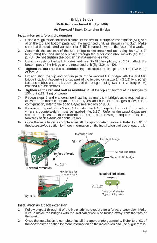
49
fi g. 3.24
fi g. 3.25
fi g. 3.26
fi g. 3.27
3 - BRIDGES
Installation as a forward extension
As Forward / Back Extension Bridge
1- Using a rough terrain forklift or a crane, lift the fi rst multi purpose insert bridge (MPI) and align the top and bottom parts with the motorized unit, as shown in fi g. 3.24. Make sure that the dedicated wall side (fi g. 3.19) is turned towards the face of the work. 2- Assemble the top part of the MPI bridge to the motorized unit using four 1" x 2" long (GR5) bolt and nut assemblies through the outer assembly sockets (fi g. 3.19, p. 48). Do not tighten the bolt and nut assemblies yet.3- Using four sets of bridge link plates and pins (TYPE 1 link plates, fi g. 3.27), attach the bottom part of the bridge to the motorized unit (fi g. 3.24, p. 49).4- Tighten the nut and bolt assemblies (4) at the top of the bridge to 100 lb-ft (136 N-m) of torque.5- Lift and align the top and bottom parts of the second MPI bridge with the fi rst MPI bridge installed. Assemble the top part of the bridges using two 1" x 3 1/2" long (GR8) bolt assemblies and the bottom part of the bridges using two 1" x 2" long (GR5) bolt and nut assemblies.6- Tighten all the nut and bolt assemblies (4) at the top and bottom of the bridges to 100 lb-ft (136 N-m) of torque.7- Repeat steps 5 and 6 to continue installing as many MPI bridges as is required and allowed. For more information on the types and number of bridges allowed in a confi guration, refer to the Load Capacities section on p. 80.8- If required, repeat steps 5 and 6 to install the MPI bridge in the back of the setup where a counterweight must be applied (fi g. 3.26). Refer to the Load Capacities section on p. 80 for more information about counterweight requirements in a forward / back extension confi guration. 9- Once the installation is complete, install the appropriate guardrails. Refer to p. 91 of the Accessories section for more information on the installation and use of guardrails.
First MPI bridge
Connector angleTo face of work
Forward extension
Required link platesTYPE 1
Second MPI bridge
Motorized unit
Position of pins for Type 1 link plates
Multi Purpose Insert Bridge (MPI)Bridge Setups
MPI bridge for counterweight
Installation as a back extension1- Follow steps 1 through 8 of the installation procedure for a forward extension. Make sure to install the bridges with the dedicated wall side turned away from the face of the work. 2- Once the installation is complete, install the appropriate guardrails. Refer to p. 91 of the Accessories section for more information on the installation and use of guardrails.

50
fi g. 3.28
fi g. 3.29
fi g. 3.30 fi g. 3.31 fi g. 3.32
3 - BRIDGES
Multi Purpose Insert Bridge (MPI)Bridge Setups
As Cantilever Bridge
1- Using a rough terrain forklift or a crane, lift the fi rst multi purpose insert bridge (MPI) (fi g. 3.30) and align the top and bottom parts with the motorized unit. Make sure that the dedicated wall side (fi g. 3.19, p. 48) is turned towards the face of the work.2- Assemble the top part of the MPI bridge to the motorized unit using four 1" x 2" long (GR5) bolt and nut assemblies through the outer assembly sockets (fi g. 3.19, p. 48). Do not tighten the bolt and nut assemblies yet.3- Using four sets of bridge link plates and pins (TYPE 1 link plates, fi g. 3.29), attach the bottom part of the bridge to the motorized unit (fi g. 3.31).4- Tighten the nut and bolt assemblies (4) at the top of the bridge to 100 lb-ft (136 N-m) of torque.5- Lift and align the top and bottom parts of the second MPI bridge with the fi rst MPI bridge installed. Assemble the top part of the bridges as described in step 2.
Installation
Required link plates
(requires the use of optional cantilever link plates)
TYPE 1
TYPE 1 link plates
Position of pins for Type 1 link plates TYPE 2
TYPE 2 link plates
First MPI bridge
Second MPI bridge
6- Using four sets of bridge link plates and pins (TYPE 2 link plates, fi g. 3.29), attach the bottom part of the bridge to the other bridge installed. It is important to note that
TYPE 2 link plates must be used to attach the bottom part of each subsequent MPI bridge installed (fi g. 3.32). Tighten all bolt assemblies to 100 lb-ft (136 N-m) of torque.7- Repeat steps 5 and 6 to continue installing as many MPI bridges as is required and allowed. For more information on the types and number of bridges allowed in a confi guration, refer to the Load Capacities section on p. 80.8- Once the installation is complete, install the appropriate guardrails. Refer to p. 91 of the Accessories section for more information on the installation and use of guardrails.
As Lateral Cantilever Bridge
1- Using a rough terrain forklift or a crane, lift the fi rst multi purpose insert bridge (MPI) and align the top and bottom parts with the motorized unit, as shown in fi g. 3.35, p. 51. Make sure that the connector angles (fi g. 3.19, p. 48) are turned towards the motorized unit.
Installation
(requires the use of optional cantilever link plates)

51
fi g. 3.33
fi g. 3.34
fi g. 3.35
fi g. 3.36
fi g. 3.37
3 - BRIDGES
Multi Purpose Insert Bridge (MPI)Bridge Setups
Required link platesTYPE 1
Position of pins
2- Assemble the top part of the MPI bridge to the motorized unit using two 1" x 2"long (GR5) bolt and nut assemblies. Do not tighten the bolt and nut assemblies yet.3- Using two bridge link plates and pins assemblies (TYPE 1 link plates, fi g. 3.34), attach the bottom part of the bridge to the motorized unit (fi g. 3.36).4- Tighten the nut and bolt assemblies (2) at the top of the bridge to 100 lb-ft (136 N-m) of torque.5- Lift the second MPI bridge and align the top and bottom parts with the fi rst MPI bridge installed. 6- Assemble the top part of the bridges using two 1" x 3 1/2" long (GR8) bolt assemblies and the bottom part of the bridges using two 1" x 2" long (GR5) bolt and nut assemblies (fi g. 3.37). It is important to note that a maximum of two bridges can be installed in a lateral cantilever confi guration. For more information on the types and number of bridges allowed in a confi guration, refer to the Load Capacities section on p. 80.
As Lateral Cantilever Bridge(requires the use of optional cantilever link plates)
Installation (cont’d)
7- Tighten all the nut and bolt assemblies (4) at the top and bottom of the bridge to 100 lb-ft (136 N-m) of torque.8- Once the installation is complete, install the appropriate guardrails. Refer to p. 91 of the Accessories section for more information on the installation and use of guardrails.
As Narrow Bearing Bridge(requires the use of optional bearing link plates)
Installation1- Choose a clear, level surface close to the work area where the bridges can be temporarily set down to assemble the bearing bridge structure. To make sure that all the bridge link plates are above the ground, set down wood cribbing or mast sections laid horizontally before lowering the bridges in place.2- Using a rough terrain forklift or a crane, lift the fi rst multi purpose insert bridge (MPI) and align the connector angle (fi g. 3.19, p. 48) with the 6' (1,8 m) bearing bridge adapter it must be attached to.3- Assemble the top part of the two bridges using two 1" x 2" long (GR5) bolt and nut assemblies. Do not tighten the bolt and nut assemblies yet.4- Using two bridge link plates and pins assemblies (TYPE 3 link plates, fi g. 3.39, p. 52), attach the bottom part of the MPI bridge to the 6' (1,8 m) bridge as shown in “A”, fi g. 3.42, p. 52.
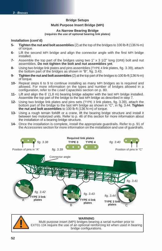
52
AB CCB
fi g. 3.38
fi g. 3.39
fi g. 3.40
fi g. 3.41
fi g. 3.42 fi g. 3.43 fi g. 3.44
3 - BRIDGES
WARNINGMulti purpose insert (MPI) bridges bearing a serial number prior to
EXT01-134 require the use of an optional reinforcing kit when used in bearing bridge confi gurations.
Multi Purpose Insert Bridge (MPI)Bridge Setups
Required link platesTYPE 3 TYPE 4
Position of pins in “A” Position of pins in “C”
Connector angle
TYPE 3 link plates TYPE 4 link
plates TYPE 3 link plates
5- Tighten the nut and bolt assemblies (2) at the top of the bridges to 100 lb-ft (136 N-m) of torque.6- Lift the second MPI bridge and align the connector angle with the fi rst MPI bridge installed.7- Assemble the top part of the bridges using two 1" x 3 1/2" long (GR8) bolt and nut assemblies. Do not tighten the bolt and nut assemblies yet.8- Using two bridge link plates and pins assemblies (TYPE 4 link plates, fi g. 3.39), attach the bottom part of the bridges as shown in “B”, fi g. 3.43.9- Tighten the nut and bolt assemblies (2) at the top part of the bridges to 100 lb-ft (136 N-m) of torque.10- Repeat steps 6 to 9 to continue installing as many MPI bridges as is required and allowed. For more information on the types and number of bridges allowed in a confi guration, refer to the Load Capacities section on p. 80.11- Lift and align the 6' (1,8 m) bearing bridge adapter with the last MPI bridge installed. Assemble the top part of the bridge to the last MPI bridge as described in step 7. 12- Using two bridge link plates and pins sets (TYPE 3 link plates, fi g. 3.39), attach the bottom part of the bridge to the last MPI bridge as shown in “C”, in fi g. 3.44. Tighten the nut and bolt assemblies to 100 lb-ft (136 N-m) of torque.13- Using a rough terrain forklift or a crane, lift the bearing bridge structure and install it between two motorized units. Refer to p. 46 of this section for more information about the installation of a bearing bridge structure. 14- Once the installation is complete, install the appropriate guardrails. Refer to p. 91 of the Accessories section for more information on the installation and use of guardrails.
As Narrow Bearing Bridge(requires the use of optional bearing link plates)
Installation (cont’d)

53
fi g. 3.45
fi g. 3.46
3 - BRIDGES
Bridge Setups
An angled bearing bridge setup is the overlapping of a bearing bridge structure at an angle on one or both motorized units of a multiple units installation (fi g. 3.45). It is important to note that fl ush bearing bridge adapters cannot be used when a bearing bridge must be overlapped at an angle.
Alternate Bridge Confi gurationsAlternate bridge confi gurations can be used with M2 Series motorized units to adapt setups to various structures (curvatures, recesses, columns, etc.).
Angled Bearing Bridge Setup(requires the use of one or two optional MPI bridges)
Multi purpose insert bridge (MPI)
Unit
Bearing bridge structure
The following installation steps must be carried out as part of a selected method of installation appropriate for the confi guration. For more information about setups and
confi gurations, refer to p. 18 of the Motorized Unit section.
Point of support of the structure
Counterweight
Positioning the fi rst motorized1- Prepare and position the fi rst motorized unit and the area where the setup will be installed as described in the instructions steps included in the method of installation appropriate for the confi guration. For more information about methods of installation, refer to p. 18 of the Motorized Unit section.
B
A
MU
AMUA Cantilever bridgeB Bearing bridgeMU Motorized unit
2- Install a cantilever multi purpose insert bridge (MPI) to support the angled bearing bridge structure. Refer to steps 1 through 4 of the installation instructions for a cantilever multi purpose insert bridge (MPI) on p. 50 of this section.
Installation of a multi purpose insert bridge (MPI)
Installation of the bearing bridge structure3- Assemble the bearing bridge structure as required and allowed. Refer to steps 1 through 6 of the installation instructions for a bearing bridge structure, on p. 46 of the Bridges section. 4- Carefully lift and lower one end of the bearing bridge structure at an angle on top of the MPI attached to the motorized unit installed. Still holding the bearing bridge structure, make sure the distance between the corners of the bearing bridge structure and the corresponding support points on the surface on which it is overlapped (shown in yellow in fi g. 3.46) is not more than 6" (15 cm) at each corner. Adjust the alignment of the structure, as necessary. Make sure the bearing bridge structure is supported at the end where no motorized unit is yet installed.
Positioning the second motorized unit5- Prepare and position the second motorized unit and the area where the setup will be installed as described in the instructions steps included in the method of installation appropriate for the confi guration. For more information about methods of installation, refer to p. 18 of the Motorized Unit section.
Max 6" (15 cm)
Max 6" (15 cm)

54
fi g. 3.47
3 - BRIDGES
Inside / Outside Corner Bearing Bridge Setup
Bridge SetupsAlternate Bridge Confi gurations
An inside or outside corner bearing bridge setup is the installation of a bearing bridge structure between two motorized units installed at a 90° angle from one another. It is important to note that fl ush bearing bridge adapters cannot be used when a bearing bridge is used in a corner confi guration.
The following installation steps must be carried out as part of a selected method of installation appropriate for the confi guration. For more information about setups and
confi gurations, refer to p. 18 of the Motorized Unit section.
1- Prepare and position the fi rst motorized unit and the area where the setup will be installed as described in the instructions steps included in the method of installation appropriate for the confi guration. For more information about methods of installation, refer to p. 18 of the Motorized Unit section.2- Determine the position of the second motorized unit while making sure that the ideal distance is kept between the two motorized units. Refer to the installation instructions for a bearing bridge structure, on p. 46 of the Bridges section.
Angled Bearing Bridge Setup(requires the use of one or two optional MPI bridges)
(requires the use of an optional 6' (1,8 m) bridge)
Installation of a multi purpose insert bridge (MPI)6- If required, install a cantilever multi purpose insert bridge (MPI) on the second motorized unit to support the bearing bridge structure at an angle. Refer to steps 1 through 4 of the installation instructions for a cantilever multi purpose insert bridge (MPI) on p. 50 of this section.
Complete the installation of the bearing bridge structure7- Carefully lower the bearing bridge structure on the motorized unit or the MPI installed, making sure the overlap is appropriate. Refer to step 4 of these installation instructions if this end of the structure is also at an angle or to the regular bearing bridge installation procedure, on p. 46 of this section.8- Make sure all safety chains are properly installed and secured. 9- Proceed with the installation steps as described in the method of installation appropriate for the confi guration. For more information about methods of installation, refer to p. 18 of the Motorized Unit section.10- Once the bearing bridge structure and the cantilever bridges are installed, apply the appropriate counterweight on the unit supporting the angled bearing bridge structure. The counterweight must be set between the mast section and the edge of the motorized unit (see fi g. 3.46). Refer to p. 89 and p. 90 of the Load Capacities section for counterweight requirements and load capacities for an angled bearing bridge confi guration.
Positioning the motorized units
WARNINGDuring the pre-installation of an angled or corner bearing bridge setup, it is important to make sure that any required counterweight is in place before
the start of any pre-installation operation.
Bearing bridge
6' (1,8 m) bridge
Edges of bearing bridge and 6' (1,8 m)bridge perfectly aligned, creating overlap area on the corner of the unit (shown in yellow)
Overlap area
Motorized unit

55
fi g. 3.48
fi g. 3.49
A
C A
B
B
C
D
D
CW
CW
3 - BRIDGES
Outside corner setup
Inside corner setup
Loads applied to the bearing bridge
must be evenly distributed
Overlap area
Location of “corner” overlap
UM
MU
A Cantilever bridgeB Bearing bridgeC Additional
6’ (1,8 m) bridgeD Cantilever on
corner unitMU Motorized unit
Installation of the 6' (1,8 m) bridge3- On the corner end of the motorized unit where the bearing bridge will be overlapped, attach a 6' (1,8 m) bridge to the motorized unit to provide support for the bearing bridge structure (see “C” in fi g. 3.48 and fi g. 3.49). Refer to the installation instructions for a cantilever bridge on p. 44 of this section.
Installation of a cantilever bridge
Bridge SetupsAlternate Bridge Confi gurations
Inside / Outside Corner Bearing Bridge Setup(requires the use of an optional 6' (1,8 m) bridge)
4- Install a cantilever bridge (see “D” in fi g. 3.48 and fi g. 3.49) on the “corner” motorized unit on the side opposite to where the bearing bridge structure will be installed.
Counterweight
Loads applied to the bearing bridge
must be evenly distributed Counterweight
Location of “corner” overlap
Complete the installation of the bearing bridge structure5- Carefully lower the bearing bridge structure on the corner motorized unit and on the 6' (1,8 m) bridge installed on the other unit (“C” in fi g. 3.48 and fi g. 3.49, making sure the overlap is appropriate at both ends. The edge of the bearing bridge must be in line with the edge of the 6' (1,8 m bridge on the “corner” unit, creating a 12" (30,5 cm) overlap on the corner of unit (see fi g. 3.47, p. 54). 6- Make sure all safety chains are properly installed and secured. 7- Once the bearing bridge structure and the cantilever bridges are installed, apply the appropriate counterweight on the unit supporting the angled bearing bridge structure. The counterweight must be set between the mast section and the edge of the motorized unit (see “CW” in fi g. 3.48 and fi g. 3.49). Refer to p. 89 and p. 90 of the Load Capacities section for counterweight requirements and load capacities for an inside or outside corner bearing bridge confi guration.8- Proceed with the installation steps as described in the method of installation appropriate for the confi guration. For more information about methods of installation, refer to p. 18 of the Motorized Unit section.
CO
RN
ER
MU
CO
RN
ER
MU
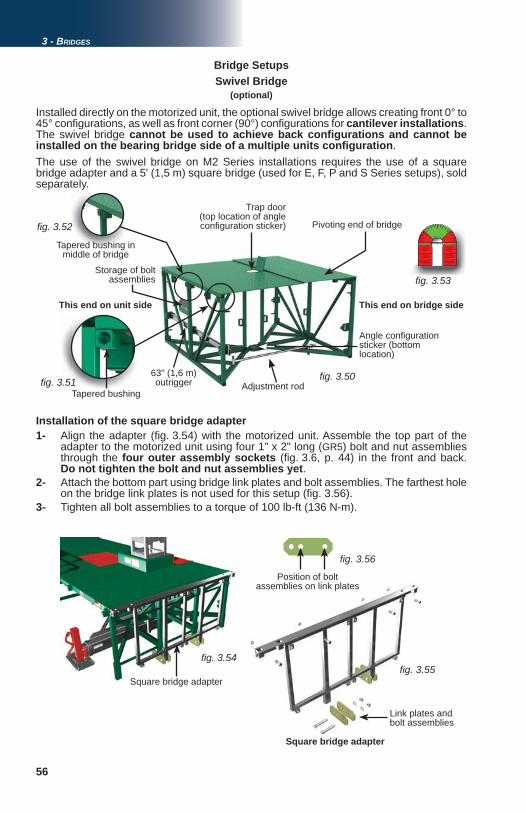
56
fi g. 3.50 fi g. 3.51
fi g. 3.55
fi g. 3.50
Cut
-out
A0800001-0004
Corner / Coin / Esquina
45o 45 o
90 o
180o
Corner / Coin / Esquina
90o
For any setup in thered zone,
please call your local distributor
Pour toute installation dans la zone rouge,
veuillez contacter votre distributeur local
Es necesario que llame a su distribuidor para
cualquier montaje en la zona roja
For any setup in thered zone,
please call your local distributor
Pour toute installation dans la zone rouge,
veuillez contacter votre distributeur local
Es necesario que llame a su distribuidor para
cualquier montaje en la zona roja
fi g. 3.52
fi g. 3.53
fi g. 3.54
2
fi g. 3.56
3 - BRIDGES
Bridge SetupsSwivel Bridge
(optional)
Installed directly on the motorized unit, the optional swivel bridge allows creating front 0° to 45° confi gurations, as well as front corner (90°) confi gurations for cantilever installations. The swivel bridge cannot be used to achieve back confi gurations and cannot be installed on the bearing bridge side of a multiple units confi guration. The use of the swivel bridge on M2 Series installations requires the use of a square bridge adapter and a 5' (1,5 m) square bridge (used for E, F, P and S Series setups), sold separately.
Square bridge adapter
Installation of the square bridge adapter1- Align the adapter (fi g. 3.54) with the motorized unit. Assemble the top part of the adapter to the motorized unit using four 1" x 2" long (GR5) bolt and nut assemblies through the four outer assembly sockets (fi g. 3.6, p. 44) in the front and back. Do not tighten the bolt and nut assemblies yet.2- Attach the bottom part using bridge link plates and bolt assemblies. The farthest hole on the bridge link plates is not used for this setup (fi g. 3.56). 3- Tighten all bolt assemblies to a torque of 100 lb-ft (136 N-m).
Square bridge adapter
Position of bolt assemblies on link plates
This end on unit side
Storage of bolt assemblies
This end on bridge side
Adjustment rod
Trap door (top location of angle confi guration sticker)
63" (1,6 m) outrigger
Pivoting end of bridge
Tapered bushing
Angle confi guration sticker (bottom location)
Link plates and bolt assemblies
Tapered bushing in middle of bridge

57
fi g. 3.57
fi g. 3.58
fi g. 3.59
3 - BRIDGES
Angle adjustment1- Make sure that the adjustment rod is installed on the appropriate side of the swivel bridge to achieve the desired confi guration. If required, remove the bolt assemblies at both ends of the adjustment rod and reinstall on the other side of the swivel bridge (fi g. 3.58).
2- Position the swivel bridge installation at the desired angle using the adjustment nuts (fi g. 3.59). Refer to the angle sticker located under the trap door on the bridge deck or on the pivot pin at the bottom of the bridge (fi g. 3.50, p. 56) to make sure the installation is at an appropriate angle. A swivel bridge confi guration may only be installed at an angle between 0 and 45 degrees or at exactly 90 degrees towards the front.
Bridge SetupsSwivel Bridge
Square bridge adapter
5' (1,5 m) bridgesSwivel bridge
Installation of the swivel bridge and the 5' (1,5 m) square bridge1- Using the tapered bushings (fi g. 3.51), align the swivel bridge with the adapter installed on the motorized unit. If the welded stoppers on the bottom trusses of the adapter and of the bridge prevent proper alignment, the swivel bridge is not properly positioned.
2- Attach the swivel bridge to the adapter using six bolt assemblies: one 5/8" x 5 1/2" (GR8) hex bolt, one 5/8" (GR8) lock washer and one 5/8" (GR8) nut in each of the four corner tapered bushings (fi g. 3.50 and fi g. 3.51, p. 56) and in either one of the tapered bushings (left or right) at the top and bottom in the middle of the bridge, fi g. 3.50 and fi g. 3.52, p. 56). Tighten all bolt assemblies to a torque of 120 lb-ft (163 N-m).
3- Repeat steps 1 and 2 to attach a 5' (1,5 cm) square bridge to the swivel bridge and to install any subsequent 5' (1,5 cm) square bridge, as required and allowed. Refer to p. 87 of the Load Capacities section for the number of bridges allowed in a swivel bridge installation.
Bolt assemblies
Adjustment nuts
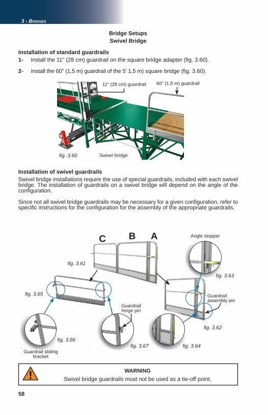
58
fi g. 3.60
fi g. 3.61
fi g. 3.62
fi g. 3.63
fi g. 3.64
fi g. 3.65
fi g. 3.66 fi gfifi g
fi g.
fi gfi g. 3.67 fi g
3 - BRIDGES
Bridge SetupsSwivel Bridge
Installation of standard guardrails1- Install the 11" (28 cm) guardrail on the square bridge adapter (fi g. 3.60).
2- Install the 60" (1,5 m) guardrail of the 5' 1,5 m) square bridge (fi g. 3.60).
11" (28 cm) guardrail
Guardrail sliding bracket
Angle stopper
Guardrail hinge pin
Guardrail assembly pin
C B A
Installation of swivel guardrailsSwivel bridge installations require the use of special guardrails, included with each swivel bridge. The installation of guardrails on a swivel bridge will depend on the angle of the confi guration.
Since not all swivel bridge guardrails may be necessary for a given confi guration, refer to specifi c instructions for the confi guration for the assembly of the appropriate guardrails.
WARNINGSwivel bridge guardrails must not be used as a tie-off point.
Swivel bridge
60" (1,5 m) guardrail

59
15
47
63
2
S
8
fi g. 3.68
3 - BRIDGES
Bridge Setups
1- Make sure that the adjustment rod is installed on the appropriate side of the swivel bridge to achieve the desired confi guration. If required, remove the bolt assemblies at both ends of the adjustment rod and reinstall it on the other side of the swivel bridge (fi g. 3.58, p. 57).
2- Lock the angle pivot between parts “A” and “B” of the swivel bridge guardrail assembly at 0° using the angle stopper (fi g. 3.63, p. 58).
3- Align the hinge tubes on the swivel bridge guardrail assembly with the hinge tubes on the 11" (28 cm) guardrail on the square bridge adapter and secure in place with guardrail assembly pins (fi g. 3.64, p. 58).
4- Insert the guardrail hinge pins on part “C” in the corresponding hinge tubes on part “B”. Secure the assembly with hairpin cotter pins.
5- Install the 60" (1,5 m) guardrail of the square bridge attached to the swivel bridge.
6- Secure part “C” of the swivel bridge guardrail assembly to the 60" (1,5 m) guardrail by tightening the bolt on the sliding bracket (fi g. 3.66, p. 58).
7- Make sure all the necessary guardrails are in place and secure (see the Accessories section on p. 91 for more information about guardrails). In all cases where workers are exposed to fall hazards greater than specifi ed by local regulations, the installation of guardrails or face guardrail supports is mandatory.
Cantilever Confi gurationsFront cantilever confi gurations (0 to 45° and 90°)
Swivel Bridge
Front 0 to 45° cantilever confi gurations
Angle locked at 0°
LEGEND
1 Part “A” of swivel bridge guardrail assembly 4 Sliding bracket to secure
guardrails together 7 Square 5' (1,5 m) bridge
2 Part “B” of swivel bridge guardrail assembly 5 11" (28 cm) guardrail 8 Adapter for square bridge
3 Part “C” of swivel bridge guardrail assembly 6 60" (1,5 m) guardrail
for square bridge S Swivel bridge

60
1
2
34
5
6
5
fi g. 3.69
3 - BRIDGES
Bridge SetupsSwivel Bridge
The optional counterweight adapter is required to install a square 5' (1,5 m) bridge to support a counterweight (not provided) in a swivel bridge installation with forward cantilever bridges. The use of a counterweight for any other swivel bridge confi guration is not advantageous and should not be considered.
Counterweight bridge
Counterweight
Counterweight adapter
Forward cantilever square bridges
Swivel bridge
Installation
Swivel Bridge Counterweight Adapter(optional)
Recommended order of installation:
1 Square bridge adapter and swivel bridge2 Cantilever bridge on opposite side of motorized unit (refer to Load Capacities section)3 Counterweight adapter4 Square 5' (1,5 m) counterweight bridge5 Square 5' (1,5 m) forward cantilever bridges (as required and allowed)6 Apply counterweight
1- Make sure that there are no bridges installed except for the swivel bridge and a 5' (1,5 m) modular bridge installed on the opposite cantilever side of the unit. For instructions on the installation of a swivel bridge, refer to p. 56 of this section. Refer to p. 57 of this section for instructions on the installation of a 5' (1,5 m) square bridge.
2- Make sure that the end of the swivel bridge that is not bolted to the adapter (pivoting end, fi g. 3.69) is supported so the two halves of the swivel bridge remain together.
3- Remove the lock bolt from the top pivot pin (fi g. 3.70, p. 61). It is not necessary to remove the lock bolt from the bottom pivot pin.
4- Lift out the top pivot pin until it clears the top part of the pivot structure (fi g. 3.71, p. 61) and it is possible to align the hole in the top plate of the counterweight adapter. It is not necessary to remove the pivot pin completely. Lift out the bottom pivot pin until it is possible to insert the bottom plate (forked) of the counterweight adapter around the pivot pin.
Pivoting end of bridge
Swivel bridge adapter

61
fi g. 3.70
fi g. 3.71
fi g. 3.72
fi g. 3.73 fi g. 3.74
3 - BRIDGES
Bridge SetupsSwivel Bridge
Counterweight adapter
Swivel bridge
Top pivot pin
Bottom pivot pin
Top plate
Bottom (forked) plate
Swivel Bridge Counterweight Adapter(optional)
Installation (cont’d)
Bolt assemblies
Counterweight bridge
Frame of swivel bridge
Counterweight bridge
5- Slide in the bottom plate of the counterweight adapter around the bottom pivot pin and align the hole of the top plate with the top pivot pin. Replace the top pivot pin.
6- Replace the lock bolt of the top pivot pin and tighten to secure.
7- Secure the counterweight adapter to the frame of the swivel bridge with bolt assemblies to lock it into position (fi g. 3.74).
8- Bolt a 5' (1,5 m) square bridge to the counterweight adapter as described in steps 1 through 3 of the installation instructions for a swivel bridge and a 5' (1,5 m) square bridge on p. 57 of this section.
9- Install forward cantilever square bridges, as required and allowed (fi g. 3.69, p. 60). Refer to the Load Capacities section on p. 80 for the number of bridges allowed in a confi guration.
10- Apply the counterweight on the square bridge attached to the counterweight adapter. For information on the type of counterweight to apply, refer to p. 88 of the Load Capacities section.
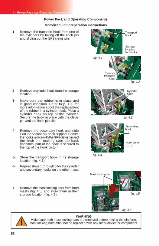
62
fi g. 4.1
fi g. 4.2
fi g. 4.3
fi g. 4.4
fi g. 4.5
fi g. 4.6
4 - POWER PACK AND OPERATING COMPONENTS
Power Pack and Operating ComponentsMotorized unit preparation instructions
WARNINGMake sure both mast locking bars are removed before raising the platform.
Mast locking bars must not be replaced with any other device or component.
1- Remove the transport hook from one of the cylinders by taking off the linch pin and sliding out the GR8 clevis pin.
2- Retrieve a cylinder hook from the storage location.
3- Make sure the rubber is in place and in good condition. Refer to p. 120 for more information about the replacement of the rubber in a cylinder hook. Place a cylinder hook on top of the cylinder. Secure the hook in place with the clevis pin and the linch pin clip.
4- Retrieve the secondary hook and slide it on the secondary hook support. Secure the hook in place with the GR8 clevis pin and the linch pin, making sure the back horizontal part of the hook is secured to the top of the hook piston.
5- Store the transport hook in its storage location (fi g. 4.1).
6- Repeat steps 1 through 5 for the cylinder and secondary hooks on the other mast.
7- Remove the mast locking bars from both masts (fi g. 4.5) and store them in their storage location (fi g. 4.6).
Cylinder hook
Secondary hook
Mast locking bar
Hook piston
Transport hook
Storage location for hooks
Remove transport
hook

63
fi g. 4.7
fi g. 4.8
fi g. 4.9
fi g. 4.10
fi g. 4.11
fi g. 4.12
4 - POWER PACK AND OPERATING COMPONENTS
Engine startup preparation instructionsPower Pack and Operating Components
1- Open the engine access panel (fi g. 4.7).
2- Pull the control post out of its storage location.
3- Slide the control post in the holding pocket until the stopper rests on top of the pocket.
4- Secure the control post in place by tightening the pocket bolt.
5- Check the hydraulic oil level to make sure it is at least 3/4 full. Replenish if necessary.
6- Check the gasoline level and refill if necessary.
44 9.9.99
fifi 4 11
Control post
Bolt
Storage location for control post
Engine access panel
Stopper
Hydraulic oil tank
Gasoline tank
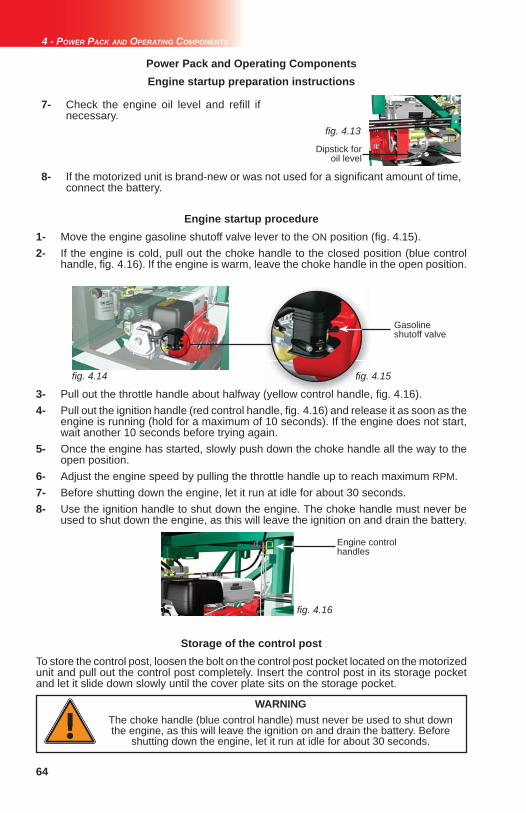
64
fi g. 4.13
fi g. 4.14 fi g. 4.15
fi g. 4.16
4 - POWER PACK AND OPERATING COMPONENTS
Power Pack and Operating Components
WARNINGThe choke handle (blue control handle) must never be used to shut down the engine, as this will leave the ignition on and drain the battery. Before
shutting down the engine, let it run at idle for about 30 seconds.
1- Move the engine gasoline shutoff valve lever to the ON position (fi g. 4.15).2- If the engine is cold, pull out the choke handle to the closed position (blue control handle, fi g. 4.16). If the engine is warm, leave the choke handle in the open position.
Engine startup procedure
Gasoline shutoff valve
Engine control handles
To store the control post, loosen the bolt on the control post pocket located on the motorized unit and pull out the control post completely. Insert the control post in its storage pocket and let it slide down slowly until the cover plate sits on the storage pocket.
Storage of the control post
Engine startup preparation instructions
7- Check the engine oil level and refi ll if necessary.
8- If the motorized unit is brand-new or was not used for a signifi cant amount of time, connect the battery.
Dipstick for oil level
3- Pull out the throttle handle about halfway (yellow control handle, fi g. 4.16).4- Pull out the ignition handle (red control handle, fi g. 4.16) and release it as soon as the engine is running (hold for a maximum of 10 seconds). If the engine does not start, wait another 10 seconds before trying again. 5- Once the engine has started, slowly push down the choke handle all the way to the open position.6- Adjust the engine speed by pulling the throttle handle up to reach maximum RPM.7- Before shutting down the engine, let it run at idle for about 30 seconds.8- Use the ignition handle to shut down the engine. The choke handle must never be used to shut down the engine, as this will leave the ignition on and drain the battery.

65
fi g. 4.17
fi g. 4.18
fi g. 4.19
fi g. 4.20
4 - POWER PACK AND OPERATING COMPONENTS
Power Pack and Operating Components
Raising the platform
WARNINGVisually make sure the cylinder hook and the secondary hook are properly engaged on a mast rung on each mast before raising or lowering platform (fi g. 4.19 and fi g. 4.20). Failure to engage hooks correctly can cause the
platform to drop, leading to equipment damage, injury, even death.
1- Before raising the platform, make sure that the motorized unit and plank outriggers clear the building, balconies, etc., that the mast tie door is open and that planking has been removed from in front of each mast when passing a tie level.
2- Lock the lowering cams on the cylinder hook and the secondary hook on each mast (fi g. 4.18).
3- Make sure that the engine is running at full throttle. Visually make sure that the cylinder hook and the secondary hook are properly engaged (fig. 4.19 and fi g. 4.20) and on the same mast rung (fi g. 4.23, p. 66) on both masts. Failure to engage the hooks correctly can cause the platform to drop.
RAISING the control levers will cause the cylinders to extend and generate a downward motion of the platformGREEN ARROWGREEN ARROW indicates to raise and hold the control levers until the cylinders extend completelyYELLOW ARROWYELLOW ARROW indicates to raise and hold the control levers until the cylinders have extended suffi ciently for the task to perform
LOWERING the control levers will cause the cylinders to retract and generate an upward motion of the platformGREEN ARROWGREEN ARROW indicates to lower and hold the control levers until the cylinders retract completelyYELLOW ARROWYELLOW ARROW indicates to lower and hold the control levers until the cylinders have retracted suffi ciently for the task to perform
SAFETY comes fi rst. The raising and lowering of the platform must be visually monitored at all times. It is mandatory to make sure that both hooks are properly engaged on a mast rung on each mast before raising or lowering the platform. Failure to engage the hooks correctly may cause the platform to drop, leading to equipment damage, injury, even death.
Mast tie door
Push pin for locking the cam
Cam locked in raising position
Incorrect
Correct
To facilitate rise and descent operations, it is suggested to engage both the cylinder hook and the secondary hook on the same mast rung on both masts, as shown in fi g. 4.23, p. 66.

66
fi g. 4.21
fi g. 4.22
fi g. 4.23
4 - POWER PACK AND OPERATING COMPONENTS
WARNINGThe use of fall protection equipment is mandatory to handle operations when passing tie levels. Properly tied to the unit, slide planks away from in front of the masts and open the mast tie doors. Close the mast tie doors once the tie
levels are passed.
WARNINGIn a bearing bridge confi guration, it is mandatory to coordinate the raising and
lowering operations on each motorized unit linked by the bearing bridge to ensure that any slope of the bridge structure does not exceed 2 degrees or
1" / 24" (35 cm / 61 cm).
Power Pack and Operating Components
Raising the platform (cont’d)
4- Raise the control levers until the hydraulic cylinders are extended completely (to a height equal to two rungs) (fi g. 4.21). The engine will slow down when the cylinders are fully extended.
5- Lower the control levers so the cylinder hooks lower enough to engage onto a mast rung.
Check visually on both masts to make sure that the cylinder hooks are properly engaged on a mast rung.
6- Lower the control levers and let the platform rise until each secondary hook is above the rung where the cylinder hook is engaged. The lift can be 10" or 20" (25,4 cm or 50,8 cm), or a height equal to one or two mast rungs.
7- Raise the control levers enough to engage the secondary hook on the mast rung on each mast. Both hooks should now be side by side on the same mast rung on both masts.
8- Repeat steps 4 through 7 to continue raising the platform.
9- Once the platform has reached the desired height, make sure that both hooks are properly engaged on the same mast rung on each mast.
2 rungs
The use of shorter planks will facilitate the passing of tie levels.

67
fi g. 4.24
fi g. 4.25
fi g. 4.26
fi g. 4.27
fi g. 4.28
fi g. 4.29
4 - POWER PACK AND OPERATING COMPONENTS
Lowering the platform
Power Pack and Operating Components
1- Before lowering the platform, make sure that the motorized unit and plank outriggers clear the building, balconies, etc., that the mast tie door is open and that planking has been removed from in front of each mast when passing a tie level.
2- Unlock the lowering cam on both the cylinder hook and the secondary hook on both masts (fi g. 4.25).
3- Make sure that the engine is running at full throttle. Visually make sure that the cylinder hook and the secondary hook are properly engaged (fig. 4.26 and fi g. 4.27) and on the same mast rung (fi g. 4.32, p. 68) on both masts. Failure to engage the hooks correctly can cause the platform to drop.
4- Lower the control levers to retract the cylinders completely so the lowering cam on each secondary hook can swing toward the mast. The engine will slow down when the cylinders are fully retracted.
5- Raise the control levers to extend the cylinders completely. The engine will slow down when the cylinders are fully extended. The platform will lower by 10" or 20" (25,4 cm or 50,8 cm), or a height equal to one or two mast rungs (fi g. 4.29).
Cam in unlocked lowering position
Incorrect
Correct
WARNINGVisually make sure the cylinder hook and the secondary hook are properly engaged on a mast rung on each mast before raising or lowering platform
(fi g. 4.26 and fi g. 4.27). Failure to engage hooks correctly can cause the platform to drop, leading to equipment damage, injury, even death.
Mast tie door
2 rungs

68
fi g. 4.30
fi g. 4.31
fi g. 4.32
4 - POWER PACK AND OPERATING COMPONENTS
Lowering the platform (cont’d)
Power Pack and Operating Components
6- Lower the control levers to retract the cylinders enough so the secondary hook is above the mast rung on each mast (but not its lowering cam).
7- Raise the control levers so the secondary hooks lower enough to engage onto the mast rungs.
Before lowering the platform, check visually to make sure that the secondary hook is properly engaged on the mast rung on both masts.
8- Raise the control levers again to extend each cylinder completely and force its lowering cam to swing toward the mast.
9- Lower the control levers to fully retract the cylinders completely. The engine will slow down when the cylinders are fully retracted.
10- Raise the control levers to extend each cylinder enough until its hook is above the mast rung (but not its lowering cam).
11- Lower the control levers so the cylinder hooks lower enough to engage onto the mast rungs.
Both the cylinder and secondary hooks will be side by side on the same mast rung on each mast.
12- Repeat steps 4 through 11 to continue lowering the platform.
13- Monitor the last 10' (3 m) of lowering to base level to ensure the proper seating of the access walkway.
14- Once the platform has been brought down to base level or to the desired height, make sure that both hooks are properly engaged on the same mast rung on each mast.
fi g. 4.3
fi g
WARNINGThe use of fall protection equipment is mandatory to handle operations when passing tie levels. Properly tied to the unit, slide planks away from in front of the masts and open the mast tie doors. Close the mast tie doors once the tie
levels are passed.
WARNINGIn a bearing bridge confi guration, it is mandatory to coordinate the raising and
lowering operations on each motorized unit linked by the bearing bridge to ensure that any slope of the bridge structure does not exceed 2 degrees or 1"
/ 24" (35 cm / 61 cm).

69
fi g. 5.1
fi g. 5.2
5 - MAST AND MAST TIES
1- To connect one mast section to another, align the mast section to be installed on top of the bottom mast section. Insert the anti-error stubs on top of the bottom section into the bottom tubes of the section to be installed, making sure the mast sections line up square and that rungs for the hooks are on the same side.2- Flip the 5/8" x 6 1/2" toggle bolt, mast clamp and fl ange nut onto the connecting lug and tighten by hand. Perform this operation for all four (4) corners.3- Tighten all toggle bolts to 120 lb-ft (163 N-m) of torque. Use a cross-pattern sequence when tightening (fi g. 5.1).4- Repeat steps 1, 2 and 3 for each mast section to be installed at every 5' (1,5 m) of rise. Install mast sections alternately – on one mast, then on the other. 5- For faster assembly, lengths of mast sections can be pre-assembled (also referred to as "sticks"). The length of pre-assembled mast allowed is equal to the height in feet (meters) authorized between tie levels for the installation. For more information about tie levels, refer to the Mast Tie Installation Schedule on p. 70 of this section. It is recommended to use an optional multiple mast handler to handle pre-assembled lengths of mast sections. For instructions on the use of the optional mast handler, refer to p. 117 of the Accessories section.6- Always make sure that the mast assemblies are plumb on both the front and side axis. 7- It is important to make sure to verify the mast bolts on each mast when lowering the platform to make sure they are in good condition and tightened to the proper torque, especially on brand-new mast sections, as the galvanized coating may have compressed. In all cases, mast bolts must be tightened to a torque of 120 lb-ft (163 N-m). Failure to tighten bolts properly may lead to serious injury or death.
Masts and Mast Ties
Installation of a mast section
The installation of mast sections must be performed with care. The front face of mast sections must always be parallel to the face of the work. It is important to verify that each mast remains parallel throughout the installation of mast sections.
Mast sections loaded on the motorized unit using a crane or a rough terrain forklift must be stored horizontally on the motorized unit to ensure good balance. Refer to the Load Capacities section on p. 80 for more information about loading the motorized unit.
WARNINGIt is important to make sure to verify the mast bolts when lowering the platform
to make sure they are in condition and are tightened to the proper torque, especially on brand-new mast sections, as the galvanized coating may have
compressed.
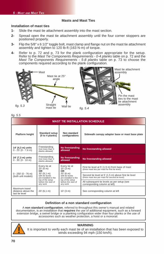
70
fi g. 5.3 fi g. 5.4
fi g. 5.5
5 - MAST AND MAST TIES
WARNINGIt is important to verify each mast tie of an installation that has been exposed to
winds exceeding 94 mph (150 km/h).
MAST TIE INSTALLATION SCHEDULE
Platform height Standard setup(0 to 4 planks)
Non standard confi gurations Sidewalk canopy adapter base or mast base plate
14' (4,3 m) units0 - 25' (0 - 7,6 m)
Freestanding(not more than 3 planks allowed)
No freestanding allowed No freestanding allowed
24' (7,3 m) units0 - 35' (0 - 10 m)
Freestanding(not more than 3 planks allowed)
No freestanding allowed No freestanding allowed
0 - 250' (0 - 76 m)(both unit models)
Every tie at 20' (6 m) OR 30' (9,1 m) with tie levels pre-installed to the top of the setup before the start of any work
Every tie at 10' (3 m) OR 20' (6 m) with tie levels pre-installed to the top of the setup before the start of any work
First tie level at 5' (1,5 m) from base of mast (three mast ties per mast for fi rst tie level)
Second tie level at 5' (1,5 m) above fi rst tie level(three mast ties per mast for second tie level)
All subsequent tie levels as per setup (see corresponding column at left)
Maximum travel distance above the last tie level
20' (6,1 m) 10' (3 m) See corresponding column at left
Masts and Mast TiesInstallation of mast ties1- Slide the mast tie attachment assembly into the mast section.2- Spread open the mast tie attachment assembly until the four corner stoppers are positioned properly.3- Flip the 5/8" x 6 1/2" toggle bolt, mast clamp and fl ange nut on the mast tie attachment assembly and tighten to 120 lb-ft (163 N-m) of torque.4- Refer to p. 72 and p. 73 for the plank confi guration appropriate for the setup. Refer to the Mast Tie Components Requirements - 0-4 planks table on p. 72 and the Mast Tie Components Requirements - 5-8 planks table on p. 73 to choose the components required according to the plank confi guration.
Mast tie at 25° angle
Wall tie
Mast tie attachment assemblyMast
Straightmast tie
Pin the mast ties to the mast tie attachment assembly
Defi nition of a non standard confi gurationA non standard confi guration, referred to throughout this owner’s manual and related
documentation, is an installation that requires the use of additional equipment, such as a forward extension bridge, a swivel bridge or a planking confi guration wider than four planks or the use of
accessories such as weather protection, a hoist or a monorail.

71
Xfi g. 5.6
OU
fi g. 5.7
fi g. 5.8
5 - MAST AND MAST TIES
Masts and Mast Ties
5- Pin the required straight mast tie to the mast tie attachment using a clevis pin and a linch pin. 6- Pin the straight mast tie to the wall tie and adjust its length until the mast is perfectly plumb on the front axis. Use the threaded rod and the pin for adjustment, leaving a maximum length of threaded rod inside the mast tie tube for added strength. 7- Install the required mast tie at a 25° angle (fi g. 5.1, p. 69) and use the threaded rod to adjust its length until the mast is perfectly plumb on the side axis. Mast ties installed at a 25° angle must be installed outside or inside, using the same confi guration on both masts, as shown in fi g. 5.6 and fi g. 5.7. Mast ties must never be installed in a parallel fashion.
WARNING - WIND SPEEDS
The erection and dismantling of a motorized unit setup (including the base, the bridges, the masts, the mast ties and all the other components) must not be conducted when wind speeds exceed 28 mph (45 km/h). Freestanding installations and setups equipped with weather protection, when allowed, must not be used with wind speeds exceeding 28 mph (45 km/h). Weather protection, when allowed, must not be used when work is performed on an open air structure. A motorized unit setup with mast ties must not be operated when wind speeds exceed 35 mph (56 km/h).
When a motorized unit is not in use- It is mandatory to leave the platform between two tie levels when the motorized unit is not in use.- Remove all loads from the setup when the motorized unit is not in use. - It is mandatory to leave all the counterweights applied on the setup in place when the motorized unit is not in use. - In a freestanding installation, when allowed, the motorized unit must be brought down to base level when not in use.- If wind speeds are expected to exceed 94 mph (150 km/h), the motorized unit must be brought down to base level when not in use.
Installation of mast ties (cont'd)
INCORRECT MAST TIE INSTALLATION
INSIDE OUTSIDE
APPROPRIATE MAST TIE INSTALLATION
Mast ties must always be installed with the angled mast tie outside or inside, as shown in fi g. 5.6 and fi g. 5.7, using the same confi guration for both masts. Mast ties must never be installed in a parallel fashion as shown in fi g. 5.8.

72
fi g. 5.9 fi g. 5.10
fi g. 5.11 fi g. 5.12
fi g. 5.13
fi g. 5.14
3
3
2
11
1
4
3
5 - MAST AND MAST TIES
MAST TIE REQUIREMENTS FOR PLANK CONFIGURATION - 0 to 4 PLANKS MAST TIE REQUIREMENTS FOR PLANK CONFIGURATION - 0 to 4 PLANKS
Ref Component 0 planks 1 plank 2 planks 3 planks 4 planks
Mast tie short assembly 1 2 0 0 0
Mast tie short male assembly 1 0 0 0 0
Mast tie assembly 0 0 1 2 2
Mast tie male assembly 0 0 1 0 0
Note: Parts required are based on number of planks x 10" (25,4 cm) + 6" to 8" (15 cm to 20 cm) of play per mast per tie level
Masts and Mast Ties
1
2
3
4
Mast Tie Requirements for Planking Confi gurations
1 2 3 4
Mast tie short assembly
Mast tie short male assembly Mast tie assembly Mast tie male
assembly
5
Mast tie extension
0 planks 1 plank
2 planks 3-4 planks
0 to 4 Planks Confi gurations

73
fi g. 5.15
fi g. 5.16
fi g. 5.17
3
3
5
5
5
fi g. 5.17 5
5
fi g. 5.18 fi g. 5.19
5
3
3
3
33
3
3
3
3 3
3
5 - MAST AND MAST TIES
Masts and Mast Ties Mast Tie Requirements for Planking Confi gurations
5 planks
1- Remove the mast tie pin holding both ends of the mast tie assembly together. 2- Insert the male end of the mast tie assembly into the female end of the mast tie extension and secure with a mast tie pin.3- Insert the male end of the mast tie extension into the female end of the mast tie assembly and secure with a mast tie pin.
5 to 8 Planks Confi gurations
1 2 3 4
Mast tie short assembly
Mast tie short male assembly Mast tie assembly Mast tie male
assembly
5
Mast tie extension
MAST TIE REQUIREMENTS FOR PLANK CONFIGURATION - 5 to 8 PLANKS MAST TIE REQUIREMENTS FOR PLANK CONFIGURATION - 5 to 8 PLANKS
Ref Component 5 planks 6 plank 7 planks 8 planks
Mast tie assembly 2 2 2 3
Mast tie extension 1 2 2 3
Note: Parts required are based on number of planks x 10" (25,4 cm) + 6" to 8" (15 cm to 20 cm) of play per mast per tie level
3
5
8 planks
Three-tie system
6-7 planks
Male end
Female end
Disassemble here and insert mast tie extension
Assembling a mast tie and a mast tie extension

74
fi g. 5.20 fi g. 5.21
fi g. 5.22
fi g. 5.23 fi g. 5.24
fi g. 5.23
fi g. 5.
5 - MAST AND MAST TIES
Masts and Mast Ties
HH
Wall
Wall tie distanceNumber
of planks
HHin (cm)
C/CC/Cin (cm)
0 8" (20 cm) minimum 11" (28 cm)1 17" (43 cm) 15" (38 cm)2 27" (69 cm) 21" (53 cm)
3 37" (94 cm) 24" (61 cm)
4 47" (119 cm) 33" (84 cm)
5 57" (145 cm) 34" (86 cm)
6 68" (173 cm) 38" (97 cm)
7 78" (198 cm) 42" (107 cm)
Distances above are given as a reference only. Tolerance rate is of ± 2" (5 cm).
Angle of Mast Ties and Wall Tie Distances
A planking confi guration with 8 planks requires a three-tie system on each mast. It is important to refer to p. 95 of the Accessories section for more information about wide plank confi gurations and their restrictions.
Wall tie distanceNumber
of planks
HHin (cm)
AAin (cm)
BBin (cm)
8 88" (223 cm) 37" (94 cm) 11" (28 cm)
Distances above are given as a reference only. Tolerance rate is of ± 2" (5 cm).
C/CC/C
HH
AABB
The planking confi gurations (5, 6, 7 and 8 planks) shown on the previous page require the use of optional outriggers and accessories. Refer to p. 95 of the Accessories section for more information on outriggers and planking confi gurations.
0 to 7 Planks Confi gurations
Angle of Mast Ties and Wall Tie Distances8 Planks Confi guration
C/CC/C
Third tie required with certain accessories
Wall
Third tie required at all times on
each mast
25° 25°
20°5°

75
fi g. 5.25
fi g. 5.26
fi g. 5.27
5 - MAST AND MAST TIES
Passing mast tie levelsThe use of fall protection equipment is mandatory to handle operations when passing tie levels. To safely pass mast tie levels, slide planks away from the front area of each mast and open the mast tie doors. The use of shorter planks will facilitate this task. It is recommended to use the designated tie point located on the motorized unit and on the substructure to anchor the fall protection equipment. For information about tie points on the units and the substructure, refer to p. 42 of the Accessories section.
Mast tie door
Removal and transport of mast sections1- To remove one mast section, loosen the toggle bolt assembly and disengage from the connecting lug (fi g. 5.27). Perform this operation for all four (4) corners.2- Pull the top mast section off the bottom mast section. If mast sections are to be stored on the platform during dismantling, make sure they are set down horizontally and distributed equally on the motorized unit.3- Store mast sections on a fl at surface away from work areas and construction traffi c.4- Masts can be removed and carried in lengths of mast sections (also referred to as "sticks"). It is recommended to use an optional multiple mast handler to handle pre-assembled lengths of mast sections. For instructions on the use of the optional mast handler, refer to p. 117 of the Accessories section.5- For best results when carrying mast sections in bundles, it is recommended to strap them in groups of nine (9). Make sure that mast sections positioned in the middle are securely strapped to the other sections to prevent them from slipping out during transport.
Removal of mast ties1- Loosen the adjustment rod on the angle mast tie until the mast tie is loose enough to be easily unfastened from the wall tie installed on the face of the work. 2- Repeat step 1 for the straight mast tie. The straight mast tie must be the last mast tie removed. 3- Repeat steps 1 and 2 for each tie level on each mast.
Angle mast tie
Straight mast tie
The use of shorter planks will facilitate the passing of tie levels.
WARNINGIt is mandatory to make sure that all tension (or compression) is released
from the mast tie before attempting to unpin it from the wall tie.
Masts and Mast Ties

76
fi g. 5.28
fi g. 5.29
fi g. 5.30
fi g. 5.31
fi g. 5.32
5 - MAST AND MAST TIES
Masts and Mast Ties
1- Install the mast tie attachment assembly as described in steps 1 through 3 of the mast tie installation procedure on p. 70.2- Slide the top part (two angle bars) of the 30-degree mast tie bracket in the mast over the mast tie attachment assembly and make sure they are inserted in both the front and back mast rungs (fi g. 5.30). 3- Slide the bottom part of the 30-degree mast tie bracket in the mast under the mast tie attachment assembly. 4- Align the top two angle bars with the bottom part of the 30-degree mast tie bracket and bolt them together using 5/8" bolt and nut assemblies (4).5- Attach the angle bracket (fi g. 5.31) to the front of the mast tie attachment assembly with 9/16" bolt, washer and nut assemblies (3). 6- Tighten all the nut and bolt assemblies to 60 lb-ft (81 N-m) of torque.
Installation of the angle bracket
Mast tie attachment assembly with 30-degree mast tie kit
Angle bracket
Mast tie bracket – type 2
Angled Mast TiesSome mast tie confi gurations require that the mast ties be attached at an angle (between 5 and 30 degrees from horizontal) through windows or other building openings (fi g. 5.32). These angled mast tie confi gurations require the use of the optional 30-degree mast tie kit (fi g. 5.28) and an anchoring system suitable for ties on a fl oor. An angled mast tie installation must not exceed a 30-degree angle from horizontal (fi g. 5.33, p. 77). It is mandatoryto use three mast ties for each tie point of an angled mast tie installation.
Only one optional mast tie extension is allowed for each mast tie in an angled mast tie confi guration.
WARNINGAn angled mast tie installation must not exceed a 30-degree angle from
horizontal. Only one optional mast tie extension is allowed for each mast tie in an angled mast tie confi guration.

77
fi g. 5.33
5 - MAST AND MAST TIES
Masts and Mast Ties
0 to 30-degree UPPER angle
0 to 30-degree LOWER angleOR
Maximum 30-degree angle UP from horizontal
Mast tie male section
Mast tie extension
Mast tie female section
Floor ties must be able to sustain 1500 lb (680 kg) of tension/compression and 3000 lb (1361 kg) of shear force.
Calculation of a mast tie angle
12" (30 cm)
12" (30 cm)
1" (2,5 cm)
7" (18 cm)
A 5-degree slope represents a 12" to 1" (30 cm to 2,5 cm) ratio
A 30-degree slope represents a 12" to 7" (30 cm to 18 cm) ratio
Angled Mast Ties
OROR
Mast tie attachment assembly with 30-degree mast tie kit
1- Remove the linch pin and clevis pin joining the two parts of the mast tie assembly together.2- Insert the male part of the mast tie assembly into an optional mast tie extension. Secure with a clevis pin and a linch pin.3- Insert this new assembly into the female part of the mast tie assembly. Secure with a clevis pin and a linch pin.4- Pin the required straight mast tie to the mast tie attachment using a clevis pin and a linch pin. 5- Pin the straight mast tie to the fl oor tie and adjust its length until the mast is perfectly plumb on the front axis. Use the threaded rod and the pin for adjustment, leaving a maximum length of threaded rod inside the mast tie tube for added strength. Floor ties must be able to sustain 1500 lb (680 kg) of tension/compression and 3000 lb (1361 kg) of shear force.6- Repeat steps 1 through 5 to install the other two required mast ties at a 25° angle (fi g. 5.20, p. 74) and use the threaded rods to adjust their length until the mast is perfectly plumb on the side axis.
Installation of extended mast ties
Maximum 30-degree angle DOWN from horizontal

78
WARNING / AVERTISSEMENT / AVISO
A0800500-0005
Les attaches murales doivent être installées sur une structure pouvant résister à une traction ou compression de 1360 kg (3000 lb) et une force de cisaillement de 680 kg (1500 lb).
Ajuster les attaches de mât de façon à ce que le mât soit d’aplomb.
Wall ties must be installed on a structure capable of withstanding 3000 lb (1360 kg) of tension or compression and 1500 lb (680 kg) of shear.
Adjust mast ties until mast is plumb.
Las ataduras murales deben ser puestos sobre una estructura capaz de resistir a una tracción o compresión de 1360 kg (3000 lb) y una fuerza de cizallamiento de 680 kg (1500 lb).
Ajustar las ataduras de mástil para poner el mástil de plomo.
fi g. 5.34 fi g. 5.35 fi g. 5.36
fi g. 5.37 fi g. 5.38
fi g. 5.39
fi g. 5.40
5 - MAST AND MAST TIES
Before attaching masts to the building using the mast tie system, wall ties must be installed on a solid component of the building structure. It is important to understand that whether the anchoring installation is a wall or fl oor type, values for tension / compression and shear forces will be inverted. Concrete slabs, columns, steel beams, relief angles and other structural elements can be used provided they and the anchoring system chosen can sustain 3000 lb (1360 kg) of tension / compression and 1500 lb (680 kg) of shear force for an anchoring installation on a wall and 1500 lb (680 kg) of tension / compression and 3000 lb (1360 kg) of shear force for an anchoring installation on a fl oor. There are 4 types of wall ties that can be used. As the installation is rising, install the wall ties as per the Mast Tie Schedule table (fi g. 5.5, p. 70). It is important to note that M1 Series wall ties do not meet minimum strength requirements for Hydro Mobile M2 equipment setups.
Wall tie typesAnchoring System
Floor or wall tie
Welded wall tie Re-usable wall tie(welded at bottom)
WARNING
It is important to note that M1 Series wall ties do not meet minimum strength requirements for Hydro Mobile M2 equipment setups.
Fixed wall tie(4" or 10 cm only)
Re-usable wall tie(welded in center)
5 1/8" (13 cm)Ø 3/4" (1,9 cm)
Wall tie bracket template
Masts and Mast Ties

79
fi g. 5.43
fi g. 5.44
fi g. 5.45
fi g. 5.46
fi g. 5.47
fi g. 5.41 fi g. 5.42
5 - MAST AND MAST TIES
Masts and Mast Ties
Installation guidelines for a welded wall tie on a beamThe welded wall tie is 6 7/8" (17,5 cm) long and should protrude from the beam by a maximum of 3 7/8" (10 cm), as shown in fi g. 5.46.
Installation of the re-usable wall tie
2" (5 cm) weld bead
3" (5 cm) weld bead
Maximum length of 3 7/8" (10 cm)
Wall tie welded to beam
Installation guidelines for fi xed wall tiesFixed wall ties can be installed on a wall between two layers of brick (fi g. 5.43). It is important to make sure that several layers of brick have been laid on top of the fi xed wall ties and that the mortar has cured properly before attaching mast ties to the wall ties. Distance between the anchoring structure and the back of the brick wall must not be greater than 1 1/2" (3,8 cm), as show in fi g. 5.44.
Installation guidelines for a re-usable wall tieUsed mainly for masonry work projects, the re-usable wall tie is installed in a cavity left unfi lled in a brick wall under construction. When dismantling the setup and removing mast ties, the re-usable wall tie is removed and the brickwork is completed.
Maximum distance1 1/2" (3,8 cm)
Anchoring System
The welded wall tie can be fastened to the beam by three 3/16" (5 mm) wide weld beads. The two weld beads along the length of the wall tie will be 3" (5 cm) long, while the weld bead along the width of the wall tie will be 2" (5 cm) long.
Installation guidelines for fl oor tiesFloor anchoring can be installed at angles ranging from 0° up to 30° from horizontal. Floor ties must be able to sustain 1500 lb (680 kg) of tension/compression and 3000 lb (1361 kg) of shear force.
Floor tie

80
6 - LOAD CAPACITIES
Load Capacities
WARNINGTo ensure safety at all times on a mast climbing work platform system, bridges should not be loaded beyond their maximum rated weight capacities. In addition, to prevent a mast climbing work platform system from stalling because of an overload, maximum rated load capacities of the motorized unit(s) should be observed. Overloading a mast climbing work platform system
could result in serious injury or death.Make sure that there is never two workers standing on the same plank outrigger at the same time.
Changes to the calculation method of load capacitiesIt is important to note that in versions prior to version 4.0 of the M2 Series owner’s manual, the load allowed to be placed on a bridge or a unit was as shown in the load capacities charts: users did not have to take into account the weight of planks or the weight of workers (including their personal tools) on the setup, except for the number of workers. The interpretation of the M2 Series load capacities diagrams has been modifi ed in order to standardize the method used for all Hydro Mobile series. For point load confi gurations, contact the Hydro Mobile technical support team.
Load capacity calculation guidelines
1- The weight of planks and any additional accessory being used must be deducted from the load capacities.2- Each worker’s weight (personal tools and equipment included) must be deducted from load capacities. 3- To ensure stability in a single unit modular setup, the length of cantilever bridges on either side of the unit must be equal at all times, with the exception of the setup shown in the single unit capacity chart for 24' (7,3 m) units. It is also recommended that the loads applied on the platform be as evenly distributed as possible.4- To ensure stability in a multiple unit modular setup, the minimum load applied on the bearing bridge must be similar to the total load applied on the cantilever bridges. 5- It is recommended that there be a maximum number of workers for each installation, calculated as follows: overall length of installation divided by 7' (2,1 m) and rounded up, PLUS two workers for each motorized unit in the installation, with at least one of those two workers being a qualifi ed user/operator for an M2 Series motorized unit and its accessories. For example, on a setup with an overall length of 108' (32,9 m), the calculation would be: 108' / 7' (or 32,9 m / 2,1 m) rounded up to 16, PLUS two workers for each motorized unit (in this case, two units) = 4, resulting in a maximum of 20 workers for the installation, including two qualifi ed users/operators. Refer to p. 5 of the Performance and Safety Rules section for the defi nition of a qualifi ed user/operator.6- The weight of each person working in a given area reduces the load capacity of that area.7- The load capacities charts stickers displayed on the motorized unit used in the setup will take precedence over the information included in this owner’s manual. 8- The load capacity for the unit is shown in the green box on the same line as the cantilever bridge chosen, both on single and multiple unit setups load capacity charts. 9- Multiple unit setups can be a combination of any cantilever bridge on one side with any bearing bridge shown on the charts. Exclusions are shown in red in the charts (see fi g. 6.3, p. 82 and fi g. 6.4, p. 83).10- To calculate the load capacity of a standard, authorized multiple unit confi guration that is not shown in the charts included in this manual, take the length of the bearing bridge to be installed and refer to the capacities of the bearing bridge in the chart that is longer and closest to it. For example, for a 48' (15 m) bearing bridge, the load capacities and positioning of a 52' (16 m) bearing bridge would be used.
The load capacities charts included in this owner’s manual apply to installations using modular bridges or old-style bridges, as well as a combination of both.
LEGEND
10’ (3 m) modular bridge assembly Length of bridge setup
5’ (1,5 m) modular bridge assembly
6’ (1,8 m) bearing bridgeadapter
Motorized unit

81
fi g. 6.1
fi g. 6.2
6 - LOAD CAPACITIES
Single unit setups [14' (4,3 m) motorized unit] – Evenly distributedSingle unit setups [14' (4,3 m) motorized unit] – Evenly distributed
34'(10,4 m)
14'(4,3 m)
10'(3 m)
5'(1,5 m)
10'(3 m)
5'(1,5 m)
2500 lb1134 kg
2500 lb1134 kg
3500 lb1588 kg
14300 lb6486 kg
13400 lb6078 kg
3500 lb1588 kg
22000 lb9979 kg
Load Capacities
Single unit setups [24' (7,3 m) motorized unit] – Evenly distributedSingle unit setups [24' (7,3 m) motorized unit] – Evenly distributed64'
(19,5 m)
20'(6 m)
20'(6 m)
15'(4,6 m)
15'(4,6 m)
10'(3 m)
10'(3 m)
5'(1,5 m)
5'(1,5 m)
1500 lb680 kg
Total 3500 lb (1588 kg)2000 lb907 kg
Total 3500 lb (1588 kg)
Total 4000 lb (1814 kg)2500 lb1134 kg
Total 4000 (1814 kg)
4500 lb2041 kg
5000 lb2268 kg
5000 lb2268 kg
24'(7,3 m)
9600 lb4354 kg
9800 lb4445 kg
10300 lb4672 kg
10400 lb4717 kg
1500 lb680 kg
2000 lb907 kg
1500 lb680 kg
2500 lb1134 kg
4500 lb2041 kg
To ensure safety at all times, refer to guidelines, warnings and legend on p. 80 for more information on load capacities. These load capacities charts apply to confi gurations using modular bridges or old-style bridges, as well as a combination of both.
22000 lb9979 kg
1500 lb680 kg
5'(1,5 m)
3000 lb1361 kg
18200 lb8255 kg
54'(16,5 m)
44'(13,4 m)
34'(10,4 m)
29'(8,8 m)
24'(7,3 m)

82
fi g. 6.3
6 - LOAD CAPACITIES
Load Capacities
Multiple unit setups [14' (4,3 m) motorized units] – Evenly distributedMultiple unit setups [14' (4,3 m) motorized units] – Evenly distributed
For point load confi gurations, contact the Hydro Mobile technical support team.
108'(32,9 m)
9400 lb4264 kg
2500 lb1132 kg
3500 lb1588 kg
10’(3 m)
14'(4,3 m)
5'(1,5 m)
10'(3 m)
14'(4,3 m)
5'(1,5 m)
Total 9000 lb4082 kg
Total 10400 lb4717 kg
62'(18,9 m)
1800 lb817 kg
52'(15,8 m)
2600 lb1179 kg
42'(12,8 m)
32'(9,8 m)
22'(6,7 m)
12'(3,7 m)
9400 lb4264 kg
9000 lb4082 kg
MAXIMUM 5' (1,5 m) cantilevers permitted
1800 lb817 kg
1800 lb817 kg
1800 lb817 kg
1800 lb817 kg
2500 lb1132 kg
3500 lb1588 kg2600 lb
1179 kg2600 lb1179 kg
2600 lb1179 kg
9000 lb4082 kg
Total 11700 lb5307 kg
3900 lb1769 kg
3900 lb1769 kg
3900 lb1769 kg
13200 lb5987 kg
13200 lb5987 kg
Total 13000 lb5897 kg
6500 lb2948 kg
6500 lb2948 kg
Total 14300 lb6486 kg
14300 lb6486 kg
Total 15600 lb7076 kg
Overall length of installation / 7' (2,1 m), rounded up
+Two (2) workers per motorized unit in the installation
108' (32,9 m) / 7' (2,1 m), rounded up 16
+Two (2) workers for each motorized unit in the installation 4
Total of workers allowed on the installation 20
Formula Calculation example for a 108' (32,9 m) installationCalculating the maximum number of workers allowed on a given installation
To ensure safety at all times, refer to guidelines, warnings and legend on p. 80 for more information on load capacities. These load capacities charts apply to confi gurations using modular bridges or old-style bridges, as well as a combination of both.
88'(26,8 m)
68'(20,7 m)
58'(17,7 m)
48'(14,6 m)
38'(11,6 m)

83
fi g. 6
.4
6 - LOAD CAPACITIES
Load Capacities14
8'(4
5,1
m)
7000
lb31
75 k
g
2500
lb11
32 k
g
62'
(18,
9 m
)20
'(6
m)
20'
(6 m
)
24'
(7,3
m)
15'
(4,6
m)
15'
(4,6
m)
10'
(3 m
)10
'(3
m)
5'(1
,5 m
)5'
(1,5
m)
52'
(15,
8 m
)
42'
(12,
8 m
)
32'
(9,8
m)
22'
(6,7
m)
12'
(3,7
m)
24'
(7,3
m)
MA
XIM
UM
15’
(4,6
m) c
antil
ever
s pe
rmitt
ed
MA
XIM
UM
10’
(3 m
) can
tilev
ers
perm
itted
MA
XIM
UM
5’ (
1,5
m) c
antil
ever
s pe
rmitt
ed
Multiple unit setups [24' (7,3 m) motorized units] – Evenly distributedMultiple unit setups [24' (7,3 m) motorized units] – Evenly distributed
For p
oint
load
con
fi gur
atio
ns, c
onta
ct th
e H
ydro
Mob
ile te
chni
cal s
uppo
rt te
am.
Tota
l 350
0 lb
1588
kg
1500
lb68
0 kg
1500
lb68
0 kg
2000
lb90
7 kg
Tota
l 900
0 lb
4082
kg
1800
lb81
7 kg
1800
lb81
7 kg
1800
lb81
7 kg
1800
lb81
7 kg
1800
lb81
7 kg
1500
lb68
0 kg
2000
lb90
7 kg
Tota
l 350
0 lb
1588
kg
7000
lb31
75 k
g
Tota
l 400
0 lb
1814
kg
7100
lb32
20 k
g
Tota
l 104
00 lb
4717
kg
2600
lb11
79 k
g26
00 lb
1179
kg
2600
lb11
79 k
g26
00 lb
1179
kg
7100
lb32
20 k
g25
00 lb
1132
kg
1500
lb68
0 kg
Tota
l 400
0 lb
1814
kg
4500
lb20
41 k
g74
00 lb
3357
kg
7400
lb33
57 k
g
Tota
l 117
00 lb
5307
kg
4500
lb20
41 k
g39
00 lb
1769
kg
3900
lb17
69 k
g39
00 lb
1769
kg
5000
lb22
68 k
g50
00 lb
2268
kg
7500
lb34
02 k
g75
00 lb
3402
kg
Tota
l 130
00 lb
5897
kg
6500
lb29
48 k
g65
00 lb
2948
kg
1320
0 lb
5987
kg
1320
0 lb
5987
kg
1430
0 lb
6486
kg
Tota
l 143
00 lb
6486
kg
Tota
l 156
00 lb
7076
kg
To ensure safety at all times, refer to guidelines, warnings and legend on p. 80 for more information on load capacities. These load capacities charts apply to confi gurations using modular bridges or old-style bridges, as well as a combination of both.
128'
(39
m)
108'
(33
m)
88'
(26,
8 m
)
68'
(20,
7 m
)
58'
(17,
7 m
)

84
fi g. 6
.5
6 - LOAD CAPACITIES
Load CapacitiesMulti purpose insert bridge (Multi purpose insert bridge (MPIMPI) – Evenly distributed) – Evenly distributed
Lateral cantilever setups — with 24' (7,3 m) motorized unitLateral cantilever setups — with 24' (7,3 m) motorized unit
AM
U 2
4' (7
,3 m
)R
emai
ning
cap
acity
BC
Min
imum
leng
thB
earin
gC
antil
ever
m
in.
Can
tilev
er
max
.C
antil
ever
Any
late
ral
or fo
rwar
d ex
tens
ion
setu
p
Any
leng
th
of s
tand
ard
bear
ing
brid
ge(fo
r cap
aciti
es,
refe
r to
bear
ing
brid
ge lo
ad c
a-pa
city
cha
rts)
No
cant
ileve
r5'
(1,5
m)
10 4
00 lb
(471
7 kg
)
2000
lb(9
07 k
g)no
t use
d31
'(9
,4 m
)
5'(1
,5 m
)10
'(3
m)
500
lb(2
27 k
g)50
0 lb
(227
kg)
44'
(13,
4 m
)
Max
imum
con
fi gur
atio
n of
3 p
lank
s at
the
end
of th
e la
tera
l can
tilev
er, s
how
n as
“D
” in
the
char
t abo
ve.
BA A A
CD
B B
C C
D D
24' (
7,3
m)
MU
24' (
7,3
m)
MU
24' (
7,3
m)
MU
To e
nsur
e sa
fety
at a
ll tim
es, r
efer
to g
uide
lines
, war
ning
s an
d le
gend
on
p. 8
0 fo
r mor
e in
form
atio
n on
load
ca
paci
ties.
The
se lo
ad c
apac
ities
cha
rts a
pply
to c
onfi g
urat
ions
usi
ng m
odul
ar b
ridge
s or
old
-sty
le b
ridge
s,
as w
ell a
s a
com
bina
tion
of b
oth.
Max
imum
1 w
orke
r on
can
tilev
er
Max
imum
1 w
orke
r on
can
tilev
er

85
fi g. 6
.6
6 - LOAD CAPACITIES
Load Capacities
Multi purpose insert bridge (Multi purpose insert bridge (MPIMPI) – Evenly distributed) – Evenly distributedForward extension setups — with 24' (7,3 m) motorized unitForward extension setups — with 24' (7,3 m) motorized unit
AM
U 2
4’ (7
,3 m
)R
emai
ning
cap
acity
CW
BC
D
Leng
th o
f fo
rwar
d ex
tens
ion
(with
3 p
lank
s at
th
e en
d)B
earin
gC
antil
ever
m
in.
Can
tilev
er
max
.
Any
late
ral
or fo
rwar
d ex
tens
ion
setu
p
Any
leng
th
of s
tand
ard
bear
ing
brid
ge(fo
r cap
aciti
es,
refe
r to
bear
ing
brid
ge lo
ad
capa
city
cha
rts)
No
cant
ileve
r5'
(1
,5 m
)76
00 lb
(344
7 kg
)no
t use
d25
00 lb
(113
4 kg
)10
00 lb
(454
kg)
not u
sed
10'
(3 m
)
5'
(1,5
m)
10'
(3 m
)65
00 lb
(294
8 kg
)
250
lb(1
13 k
g)20
00 lb
(907
kg)
2000
lb(9
07 k
g)no
t use
d10
'(3
m)
5'
(1,5
m)
15'
(4,6
m)
1000
lb(4
54 k
g)15
00 lb
(680
kg)
500
lb(2
27 k
g)50
0 lb
(227
kg)
17'
(5,2
m)
Max
imum
con
fi gur
atio
n of
3 p
lank
s at
the
end
of th
e fo
rwar
d ex
tens
ion,
sho
wn
as “
E” in
the
char
t abo
ve.
BA
C
D
24' (7,3 m) MU
Max
imum
1 w
orke
r on
exte
nsio
n
CW
E
To e
nsur
e sa
fety
at a
ll tim
es, r
efer
to g
uide
lines
, war
ning
s an
d le
gend
on
p. 8
0 fo
r m
ore
info
rmat
ion
on lo
ad c
apac
ities
. The
se lo
ad c
apac
ities
cha
rts a
pply
to
confi
gur
atio
ns u
sing
mod
ular
brid
ges
or o
ld-s
tyle
brid
ges,
as
wel
l as
a co
mbi
natio
n of
bot
h.

86
fi g. 6
.7
6 - LOAD CAPACITIES
Load Capacities
Multi purpose insert bridge (Multi purpose insert bridge (MPIMPI) – Evenly distributed) – Evenly distributedNarrow bearing bridge setups — with 24' (7,3 m) motorized unitNarrow bearing bridge setups — with 24' (7,3 m) motorized unit
BC
DF
E24
' (7,
3 m
) M
U
24' (
7,3
m)
MU
24' (
7,3
m)
MU
24' (
7,3
m)
MU
24' (
7,3
m)
MU
A A
A A A
BC
DF
E
BC
DF
E
WA
RN
ING
Onl
y co
nfi g
urat
ions
with
a m
axim
um o
f thr
ee p
lank
s ar
e al
low
ed a
t all
times
. The
con
fi gur
atio
ns s
how
n ab
ove
are
auth
oriz
ed fo
r mul
ti pu
rpos
e br
idge
s ( M
PI)
with
se
rial n
umbe
r EX
T01-
134
and
up O
NLY
. Spe
cial
rein
forc
ing
kits
mus
t be
used
with
MP
I brid
ges
havi
ng p
revi
ous
seria
l num
bers
. To
ensu
re s
afet
y at
all
times
, ref
er
to g
uide
lines
, war
ning
s an
d le
gend
on
p. 8
0 fo
r mor
e in
form
atio
n on
load
cap
aciti
es. T
hese
load
cap
aciti
es c
harts
app
ly to
con
fi gur
atio
ns u
sing
mod
ular
brid
ges
or o
ld-s
tyle
brid
ges,
as
wel
l as
a co
mbi
natio
n of
bot
h.
A24
' (7,
3 m
) M
U
A24
' (7,
3 m
) mot
oriz
ed u
nit
Rem
aini
ng c
apac
ityB
CD
EF
24’ (
7,3
m) m
otor
ized
uni
tR
emai
ning
cap
acity
Min
imum
le
ngth
Bea
ring
Can
tilev
er m
in.
Can
tilev
er m
ax.
Any
leng
th o
f st
anda
rd b
earin
g br
idge
(for c
apac
ities
, ref
er
to b
earin
g br
idge
lo
ad c
apac
ity
char
ts)
No
cant
ileve
r5'
(1,5
m)
8500
lb(3
856
kg)
5700
lb(2
585
kg)
not u
sed
not u
sed
not u
sed
not u
sed
8500
lb(3
856
kg)
66'
(20,
1 m
)
No
cant
ileve
r10
'(3
m)
2400
lb(1
089
kg)
2400
lb(1
089
kg)
not u
sed
not u
sed
not u
sed
73'
(22,
3 m
)
No
cant
ileve
r10
'(3
m)
1550
lb(7
03 k
g)15
50 lb
(703
kg)
1550
lb(7
03 k
g)no
t use
dno
t use
d80
'(2
4,4
m)
No
cant
ileve
r15
’(4
,6 m
)10
00 lb
(454
kg)
1000
lb(4
54 k
g)10
00 lb
(454
kg)
1000
lb(4
54 k
g)no
t use
d87
'(2
6,5
m)
No
cant
ileve
r15
'(4
,6 m
)70
0 lb
(318
kg)
700
lb(3
18 k
g)70
0 lb
(318
kg)
700
lb(3
18 k
g)70
0 lb
(318
kg)
95'
(29
m)
6' (1
,8 m
) br
idge
6' (1
,8 m
) br
idge
6' (1
,8 m
) br
idge
6' (1
,8 m
) br
idge
6' (1
,8 m
) br
idge
6' (1
,8 m
) br
idge
Max
imum
2 w
orke
rs o
n be
arin
g br
idge
Max
imum
2 w
orke
rs o
n be
arin
g br
idge

87
fi g. 6
.8
fi g. 6
.9
6 - LOAD CAPACITIES
Load Capacities Sw
ivel
brid
ge in
stal
latio
n on
a 2
4' (7
,3 m
) mot
oriz
ed u
nit
Swiv
el b
ridge
inst
alla
tion
on a
24'
(7,3
m) m
otor
ized
uni
tSi
ngle
uni
t (Fr
ont 0
-45
degr
ees)
Sing
le u
nit (
Fron
t 0-4
5 de
gree
s)
Top
view
Rea
r vie
w
To ensure safety at all times, refer to load calculation guidelines and warnings on p. 80.
LEG
END
5' (1
,5 m
) squ
are
brid
ge a
ssem
bly
Leng
th o
f brid
ge s
etup
Squ
are
brid
ge a
dapt
erS
wiv
el b
ridge
At
this
end
, it
is m
anda
tory
to
inst
all
a br
idge
. The
onl
y br
idge
con
fi gur
atio
ns
allo
wed
are
a c
antil
ever
brid
ge m
easu
ring
at le
ast 5
' (1,
5 m
) and
a m
axim
um o
f 10'
(3
m) w
ith c
apac
ities
as
show
n in
the
load
ca
paci
ties
char
ts f
or s
ingl
e un
it se
tups
(s
ee fi
g. 6
.2, p
. 81)
— O
R —
an
y be
arin
g br
idge
con
fi gur
atio
n sh
own
in
the
load
cap
aciti
es c
harts
for m
ultip
le u
nit
setu
ps (s
ee fi
g. 6
.3, p
. 82)
— O
R —
any
swiv
el c
onfi g
urat
ion
show
n on
thi
s lo
ad c
apac
ity c
hart.
700
lb31
8 kg
300
lb13
6 kg
300
lb13
6 kg
1000
lb45
4 kg
500
lb22
7 kg
2000
lb90
7 kg
15' (
4,6
m)
10' (
3 m
)
Tota
l 130
0 lb
590
kg
Tota
l 150
0 lb
680
kg
Tota
l 200
0 lb
907
kg

88
A B C
A B
A B C
15' (4,6 m)
10' (3 m)
fi g. 6.10
fi g. 6.11
fi g. 6.12
fi g. 6.13
6 - LOAD CAPACITIES
Load Capacities Swivel bridge installation on a 24' (7,3 m) motorized unit Swivel bridge installation on a 24' (7,3 m) motorized unit
Single unit with counterweight adapter — Front 90 degreesSingle unit with counterweight adapter — Front 90 degrees
LEGEND5' (1,5 m) square bridge assembly Length of bridge setup
Square bridge adapter Swivel bridge
Counterweight adapter Counterweight
To ensure safety at all times, refer to load calculation guidelines and warnings on p. 80.
CW
CW
3
CWLoad capacities for two
bridges
300 lb(136 kg)
1000 lb(453 kg)
1000 lb(453 kg)
500 lb(227 kg)
1500 lb(680 kg)
1000 lb(453 kg)
500 lb(227 kg)
2000 lb(907 kg)
750 lb(340 kg)
1000 lb(453 kg)
1500 lb(680 kg)
1250 lb(567 kg)
1000 lb(453 kg)
1950 lb(885 kg)
1000 lb(453 kg)
At this end, it is mandatory to install a bridge. The only bridge configurations allowed are a cantilever bridge measuring at least 5' (1,5 m) and a maximum of 10' (3 m) with capacities as shown in the load capacities charts for single unit setups (see fi g. 6.2, p. 81)
— OR —any bearing bridge confi guration shown in the load capacities charts for multiple unit setups (see fi g. 6.3, p. 82).
es
CWLoad capacities for three
bridges
300 lb(136 kg)
900 lb (408 kg) evenly distributed on three bridges
— OR —600 lb (272 kg) on one of the three bridges
800 lb(363 kg)
1200 lb (544 kg) evenly distributed on three bridges
— OR —800 lb (363 kg) on one of the three bridges
1100 lb(499 kg)
1400 lb (635 kg) evenly distributed on three bridges
— OR —950 lb (431 kg) on one of the three bridges
1500 lb(680 kg)
1700 lb (771 kg) evenly distributed on three bridges
— OR —1150 lb (522 kg) on one of the three bridges
1600 lb(726 kg)
1800 lb (816 kg) evenly distributed on three bridges
— OR —1200 lb (544 kg) on one of the three bridges
A B C
A B
CW
NO OTHER CONFIGURATION THAN THOSE ABOVE ARE ALLOWED AT THIS END

89
fi g. 6
.14
6 - LOAD CAPACITIES
Load Capacities Angled and Corner Installations – Inside Corner Angled and Corner Installations – Inside Corner
with 24' (7,3 m) motorized unitswith 24' (7,3 m) motorized units
AM
U #
1B
MU
#2
C
Can
tilev
er le
ngth
Rem
aini
ng
capa
city
Leng
thC
apac
ityR
emai
ning
ca
paci
tyC
antil
ever
le
ngth
Non
e5'
(1,5
m)
10' (
3 m
)15
' (4,
6 m
)20
' (6,
1 m
)
CW
=
1000
lb
(454
kg)
No
CW
Cap
aciti
es
as s
how
n on
fi g.
6.4
, p.
83
No
CW
Cap
aciti
es
as s
how
n on
fi g.
6.4
, p.
83
No
CW
Cap
aciti
es
as s
how
n on
fi g.
6.4
, p.
83
No
CW
Cap
aciti
es
as s
how
n on
fi g.
6.4
, p.
83
10,6
00 lb
(480
8 kg
)
12' (
3,7
m)
6800
lb(3
084
kg)
11,5
00 lb
(521
6 kg
)
Any
ca
ntile
ver
as s
how
n on
fi g.
6.4
, p.
83
22' (
6,7
m)
5400
lb(2
449
kg)
32' (
9,8
m)
4000
lb(1
814
kg)
AM
U #
1
MU # 2
24' (
7,3
m)
mot
oriz
ed u
nit
24' (7,3 m)motorized unit BC
CW
Cou
nter
wei
ght m
ust b
e in
stal
led
betw
een
the
mas
t and
the
edge
of
the
unit
Insi
de c
orne
r

90
fi g. 6
.15
6 - LOAD CAPACITIES
Load Capacities
AM
U #
1B
MU
#2
CC
antil
ever
leng
thR
emai
ning
ca
paci
tyLe
ngth
Cap
acity
Rem
aini
ng
capa
city
Can
tilev
er
leng
thN
one
5' (1
,5 m
)10
' (3
m)
15' (
4,6
m)
20' (
6,1
m)
CW
=
2500
lb
(113
4 kg
)
CW
=15
00 lb
(680
kg)
Rem
aini
ng
capa
city
3500
lb(1
588
kg)
CW
=50
0 lb
(227
kg)
Rem
aini
ng
capa
city
4000
lb(1
814
kg)
No
CW
Cap
aciti
es
as s
how
n on
fi g.
6.4
, p.
83
No
CW
Cap
aciti
es
as s
how
n on
fi g.
6.4
, p.
83
8000
lb(3
629
kg)
12' (
3,7
m)
11,5
00 lb
(521
6 kg
)
8900
lb(4
037
kg)
Any
ca
ntile
ver
as s
how
n on
fi g.
6.4
, p.
83
22' (
6,7
m)
10,5
00 lb
(476
3 kg
)
32' (
9,8
m)
9000
lb(4
082
kg)
42' (
12,8
m)
7500
lb(3
402
kg)
52' (
15,8
m)
6500
lb(2
948
kg)
62' (
18,9
m)
5000
lb(2
268
kg)
AM
U #
1
MU # 2
24' (
7,3
m)
mot
oriz
ed u
nit
24' (7,3 m)motorized unit BC
Angled and Corner Installations – Outside Corner Angled and Corner Installations – Outside Cornerwith 24' (7,3 m) motorized unitswith 24' (7,3 m) motorized units
CW
Cou
nter
wei
ght m
ust b
e in
stal
led
betw
een
the
mas
t and
the
edge
of
the
unit
Out
side
cor
ner

91
fi g. 7.1 fi g. 7.2
fi g. 7.3
fi g. 7.4
fi g. 7.5
7 - ACCESSOIRES
Guardrail leg
Guardrail pocket End guardrail pocket
Guardrails In all cases where workers are exposed to fall hazards greater than specifi ed by local regulations, the installation of appropriate guardrails is mandatory to ensure safety.
1- Slide the guardrail legs in the guardrail pockets at the top of the motorized unit or the bridge (fi g. 7.1). 2- To secure the guardrail in place, tighten the bolt in each guardrail pocket to a torque of 30 lb-ft (41 N-m). 3- Install as many guardrails as is required by the setup.
Installation of standard bridge guardrails
1- Align an end guardrail pocket with an outer assembly socket at one end of the motorized unit or the bridge (fi g. 7.3). Secure in place with a 1" x 2" long (GR5) bridge bolt assembly. 2- Repeat step 1 to install the second end guardrail pocket in the opposite corner. 3- Slide the guardrail legs in the end guardrail pockets (fi g. 7.4). 4- To secure the end guardrail in place, tighten the bolt in each guardrail pocket to a torque of 30 lb-ft (41 N-m). 5- Install as many end guardrails as is required by the setup.
Installation of end guardrails
End guardrail
Safety Accessories SAFETY comes fi rst. While most hazards that may occur when operating an M2 Series motorized unit setup can be avoided by using extreme care and common sense, the use of safety accessories, such as a rest platform and appropriate guardrails and plank support outriggers, is recommended when areas and activities involve heights or positioning of the setup that put workers at risk.
Face guardrail supports must be installed when the distance between the end of planking (or deck, if not using planks) and the structure is greater than what local regulations allow or 6" (15 cm) (ex. recess in a wall, end of a building, etc.), the most stringent of conditions taking precedence over the others. On all M2 Series motorized units and bridges, the face guardrail supports can be installed at the bottom or top outrigger position.
Face Guardrail Supports(optional)
Installation1- If there are no outriggers installed, install the outriggers at the top or bottom position, as required. Refer to p. 95 for instructions on the installation of outriggers. Make sure not to install any plank stop pins. If outriggers are already installed, remove the plank stop pins and proceed to step 2.
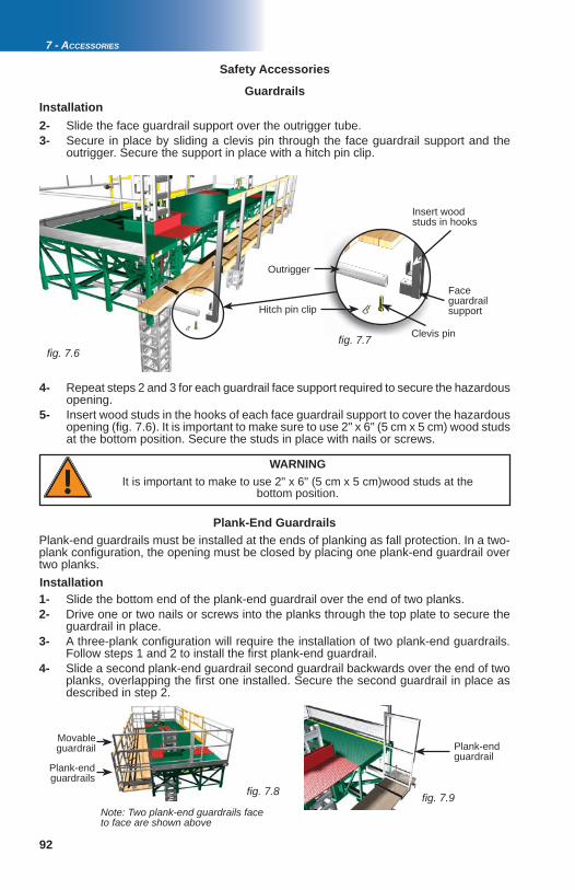
92
fi g. 7.6 fi g. 7.7
fi g. 7.8 fi g. 7.9
7 - ACCESSORIES
Guardrails
Face guardrail support
Clevis pin
Hitch pin clip
Outrigger
Insert wood studs in hooks
Safety Accessories
WARNINGIt is important to make to use 2" x 6" (5 cm x 5 cm)wood studs at the
bottom position.
Installation2- Slide the face guardrail support over the outrigger tube.3- Secure in place by sliding a clevis pin through the face guardrail support and the outrigger. Secure the support in place with a hitch pin clip.
4- Repeat steps 2 and 3 for each guardrail face support required to secure the hazardous opening. 5- Insert wood studs in the hooks of each face guardrail support to cover the hazardous opening (fi g. 7.6). It is important to make sure to use 2" x 6" (5 cm x 5 cm) wood studs at the bottom position. Secure the studs in place with nails or screws.
Plank-end guardrail
Installation1- Slide the bottom end of the plank-end guardrail over the end of two planks.2- Drive one or two nails or screws into the planks through the top plate to secure the guardrail in place. 3- A three-plank confi guration will require the installation of two plank-end guardrails. Follow steps 1 and 2 to install the fi rst plank-end guardrail.4- Slide a second plank-end guardrail second guardrail backwards over the end of two planks, overlapping the fi rst one installed. Secure the second guardrail in place as described in step 2.
Plank-end guardrails must be installed at the ends of planking as fall protection. In a two-plank confi guration, the opening must be closed by placing one plank-end guardrail over two planks.
Plank-End Guardrails
Note: Two plank-end guardrails face to face are shown above
Plank-end guardrails
Movable guardrail
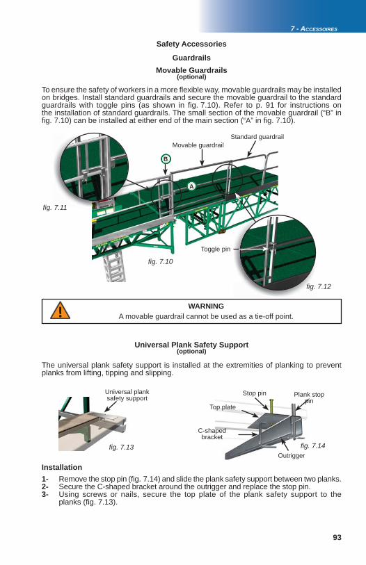
93
fi g. 7.10
fi g. 7.11
fi g. 7.12
B
fi g. 7.13 fi g. 7.14
A
7 - ACCESSOIRES
GuardrailsMovable Guardrails
To ensure the safety of workers in a more fl exible way, movable guardrails may be installed on bridges. Install standard guardrails and secure the movable guardrail to the standard guardrails with toggle pins (as shown in fi g. 7.10). Refer to p. 91 for instructions on the installation of standard guardrails. The small section of the movable guardrail (“B” in fi g. 7.10) can be installed at either end of the main section (“A” in fi g. 7.10).
(optional)
Toggle pin
Movable guardrailStandard guardrail
Safety Accessories
WARNINGA movable guardrail cannot be used as a tie-off point.
The universal plank safety support is installed at the extremities of planking to prevent planks from lifting, tipping and slipping.
Top plate
Stop pin
Outrigger
Plank stop pin
C-shaped bracket
1- Remove the stop pin (fi g. 7.14) and slide the plank safety support between two planks.2- Secure the C-shaped bracket around the outrigger and replace the stop pin. 3- Using screws or nails, secure the top plate of the plank safety support to the planks (fi g. 7.13).
Installation
Universal plank safety support
Universal Plank Safety Support(optional)

94
fi g. 7.15
fi g. 7.16 fi g. 7.17
fi g. 7.18
7 - ACCESSORIES
Retractable Rest Platform(optional)
The use of an automatically retractable rest platform is recommended to reach work areas at heights between 30' and 69' (9 m and 21 m). It is not recommended to climb up the mast to reach work areas at heights over 69' (21 m) because of the time and effort required to reach such heights. The use of alternate equipment compliant with local regulations, such as a rapid mast climber, a transport platform system, or a conventional scaffold stair system will prove to be more effi cient. Refer to local regulations for more information. It is recommended to inspect the rest platform before every working shift to make sure it is clean and in good working condition.Installation1- For safety reasons, it is recommended that the rest platform be installed from the platform of the motorized unit or from a man basket underneath the motorized unit. The rest platform must be installed on the back side of the mast, when the platform of the motorized unit has been raised to more than 30' (9 m) from base level. 2- Remove the 3/8" nuts and bolts from the folder part (fi g. 7.17).3- Unfold the rest platform and leave the handle on top.4- Slide the rest platform inside the mast with its rectangular step resting against the back side of the mast (fi g. 7.16).5- Install the folder part on a rung facing the wall using 3/8" bolts and nuts.6- Let the rest platform retract slowly inside the mast.7- Remove the 3/8" bolt and nut from the handle.8- Install the handle 5 rungs above the rest platform (fi g. 7.18). Fasten with the 3/8" bolt and nut.9- Test the rest platform by raising the handle. Doing so will retrieve the rest platform from inside the mast. When the handle is released the rest platform will fold and retract inside the mast.10- If the rest platform unfolds and retracts as and when it should, it is safe to use the rest platform.
Safety Accessories
In useRetracted
This side facing wall
Folder part
3/8" bolts and nutsHandle
1- Climb up the mast until one step above the rest platform.
2- Raise the handle to a vertical position to retrieve the rest platform from inside the mast.
3- Step on the rest platform only when the handle is in a vertical position.
4- Once on the rest platform, release the handle.
5- Resuming the climb up the mast will make the rest platform retract into the mast automatically.
Using the retractable rest platform
Handle
5 ru
ngs
or 5
0" (1
,3 m
)
Rest platform
Rest platform area
Wall

95
fi g. 7.19
fi g. 7.20
fi g. 7.21
7 - ACCESSOIRES
M2 Series motorized units and bridges are shipped with outriggers that may be used at the top or bottom position. Plank support outriggers must be installed 5' (1,5 m) from one another. The 72" (183 cm) outrigger, installed at the bottom position close to the walkway assembly, must not be replaced by any other outrigger. Installing any outrigger other than the 72" (183 cm) outrigger in front of the walkway will lead to damages to the walkway assembly and could lead to injuries.The size and number of outriggers required will vary according to the planking confi guration. Planking confi gurations of fi ve to eight planks will require the use of additional, optional components such as longer outriggers and cross boxes. Refer to the Outrigger Selectiontable (fi g. 7.19) for more information about the size and number of outriggers required for each planking confi guration. Refer also to p. 96 for more information on the installation and use of doubled outriggers.For any outrigger confi guration other than those described in this owner’s manual, contact the Hydro Mobile technical support team.
Outriggers
OUTRIGGER SELECTION TABLE OUTRIGGER SELECTION TABLE
Planking confi guration Outrigger size
0 to 4 planks 2 1/2" x 1 1/2" x 3/16" x 72"(6,4 cm x 3,8 cm x 0,5 cm x 183 cm)(standard outrigger, as provided with unit or bridge)
SINGLE
5 planks * 2 1/2" x 1 1/2" x 1/4" x 84"(6,4 cm x 3,8 cm x 0,6 cm x 213 cm)
SINGLE
6 planks * 2 1/2" x 1 1/2" x 1/4" x 120"(6,4 cm x 3,8 cm x 0,6 cm x 305 cm)
DOUBLED
7 planks * 2 1/2" x 1 1/2" x 1/4" x 120"(6,4 cm x 3,8 cm x 0,6 cm x 305 cm)
DOUBLED
8 planks * 2 1/2" x 1 1/2" x 1/4" x 120"(6,4 cm x 3,8 cm x 0,6 cm x 305 cm)
DOUBLED
* Refer to the planking confi guration guidelines for more information.
Planking confi gurations
Planking confi guration guidelines
fig 7 20
PLANKING CONFIGURATIONS – WIDTH ALLOWED ON INSTALLATIONPLANKING CONFIGURATIONS – WIDTH ALLOWED ON INSTALLATION
Number of planks Motorized unit Bearing bridge Cantilever bridge(s)
0 to 4 planks 100% of total width 100% of total width 100% of total width
5 to 8 planks 100% of total width 50% of total width Max width 5' (1,5 m)
WARNINGThe 72" (183 cm) outrigger installed close to the walkway assembly must
not be replaced by any other outrigger
Plank stop pin
Hitch pin clip
Clevis pin and hitch pin clip
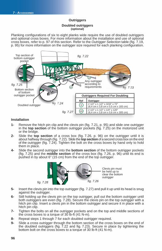
96
fi g. 7.22
fi g. 7.23
fi g. 7.24
fi g. 7.25
fi g. 7.27
fi g. 7.28 fi g. 7.26
fig. 7.2
fig. 7
72
120
72
120
7 - ACCESSORIES
Installation1- Remove the hitch pin clip and the clevis pin (fi g. 7.21, p. 95) and slide one outrigger in the top section of the bottom outrigger pockets (fi g. 7.25) on the motorized unit or the bridge. 2- Slide the top section of a cross box (fi g. 7.26, p. 96) on the outrigger until it is about halfway through (fi g. 7.22). Slide the top section of a second cross box on the end of the outrigger (fi g. 7.24). Tighten the bolt on the cross boxes by hand only to hold them in place. 4- Slide the second outrigger into the bottom section of the bottom outrigger pockets (fi g. 7.25) and the middle section of the cross box (fi g. 7.26, p. 96) until its end is pushed in by about 6" (15 cm) from the end of the top outrigger.
Outriggers Doubled outriggers
(optional)
Planking confi gurations of six to eight planks wide require the use of doubled outriggers and optional cross boxes. For more information about the installation and use of optional cross boxes, refer to p. 97 of this section. Refer to the Outrigger Selection table (fi g. 7.19, p. 95) for more information on the outrigger size required for each planking confi guration.
Doubled outrigger
Clevis pin must be held up to clear the bottom outrigger
5- Insert the clevis pin into the top outrigger (fi g. 7.27) and pull it up until its head is snug against the outrigger. 6- Still holding up the clevis pin on the top outrigger, pull out the bottom outrigger until both outriggers are even (fi g. 7.28). Secure the clevis pin on the top outrigger with a hitch pin clip. Insert a clevis pin in the bottom outrigger and secure it in place with a hitch pin clip. 7- Tighten the bolts on all the outrigger pockets and on the top and middle sections of the cross boxes to a torque of 30 lb-ft (41 N-m).8- Repeat steps 1 through 7 for each doubled outrigger required. 9- Slide a cross outrigger through the bottom section of the cross boxes on the end of the doubled outriggers (fi g. 7.22 and fi g. 7.23). Secure in place by tightening the bottom bolt on the cross boxes to a torque of 30 lb-ft (41 N-m).
Top section of bottom outrigger
Bottom section of bottom
outrigger pocket
Any outrigger according to requirements
7
Outriggers Required For Doubling
Ref Outrigger2 1/2" x 1 1/2" x 3/16" x 72"(6,4 cm x 3,8 cm x 0,5 cm x 183 cm)2 1/2" x 1 1/2" x 1/4" x 120"(6,4 cm x 3,8 cm x 0,6 cm x 305 cm)
72
120

97
fi g. 7.29
fi g. 7.30
fi g. 7.31
12084
84
120
12084
84
fi g. 7.32
fi g. 7.33
7 - ACCESSOIRES
Cross boxes are used to install auxiliary outriggers, as required when planking the inside corner of a forward extension or the recessed area in a wall. Cross boxes are also used when doubling outriggers is required.Installation1- Remove the clevis pin, hitch pin clip and plank stop pin (fi g. 7.21, p. 95) from two outriggers.2- Slide a cross box on the back and the front of each of the two outriggers (fi g. 7.29). Replace the clevis pin, hitch pin clip and plank stop pin on each outrigger and tighten the pocket bolts on both outriggers.
Cross Boxes(optional)
Cross boxes installed on the front of two
outriggers
Special planking confi gurations may be required according to job site requirements, to install planking in areas not covered by standard planking. Only the following three non standard planking confi gurations are allowed. The following planking confi gurations will require the use of optional cross boxes and, in some cases, optional 120" (305 cm) outriggers. It is mandatory to install the cross boxes as close to the bridge outrigger pockets as possible.
Outriggers
Non Standard Planking Confi gurations
3- Slide the cross outriggers through the cross boxes until they are halfway through.4- Install a cross box on each cross outrigger and extend each outrigger in position.5- Slide auxiliary outriggers through the cross boxes on the cross outriggers until they are in position. Secure them in place with a clevis pin and a hitch pin clip. Install a plank stop pin in each of the auxiliary outriggers.6- Once the planks are in place, adjust the auxiliary outriggers until the plank stop pins rest snugly against the planks. 7- Secure the outriggers in place by tightening all the bolts on the cross boxes to a torque of 30 lb-ft (41 N-m).
Top section
Middle section
Bottom section
Outriggers Required for Non Standard planking Confi guration #1
Ref Quantity Outrigger
4 2 1/2" x 1 1/2" x 1/4" x 84"(6,4 cm x 3,8 cm x 0,6 cm x 213 cm)
3 2 1/2" x 1 1/2" x 1/4" x 120"(6,4 cm x 3,8 cm x 0,6 cm x 305 cm)
Non Standard Planking Confi guration #1
84
3 planks Maximum 2 planks at this end
120
WallPlanking
Planking
Bridge Outriggers

98
fi g. 7.34
fi g. 7.35
fi g. 7.36
fi g. 7.37
72
120
120
120
72
72
72
84
84
fi g. 7.38
84
84
84
84
fi g. 7.39
7 - ACCESSORIES
OutriggersNon Standard Planking Confi gurations
Non Standard Planking Confi guration #2
Outriggers Required for Non Standard planking Confi guration #2
Ref Quantity Outrigger
4 2 1/2" x 1 1/2" x 3/16" x 72"(6,4 cm x 3,8 cm x 0,5 cm x 183 cm)
2 2 1/2” x 1 1/2" x 1/4" x 84"(6,4 cm x 3,8 cm x 0,6 cm x 213 cm)
3 2 1/2" x 1 1/2" x 1/4" x 120"(6,4 cm x 3,8 cm x 0,6 cm x 305 cm)
Outriggers Required for Non Standard planking Confi guration #3
Ref Quantity Outrigger
6 2 1/2" x 1 1/2" x 1/4" x 84"(6,4 cm x 3,8 cm x 0,6 cm x 213 cm)
Non Standard Planking Confi guration #3
Maximum 2 planks
84
120
72
Any outrigger according to requirements Wall
Bridge
Pla
nkin
g
This planking confi guration can be used for planking recessed areas
84
Outriggers
Wall
Wall
Planking
Bridge Outriggers
Maximum 8 planks

99
fi g. 7.40
7 - ACCESSOIRES
Outriggers used at the top position can be inserted either from the front or the back of the motorized unit or the bridge. In a confi guration where 72" (183 cm) outriggers are used at the top position only, the maximum width of planking allowed is four planks. In a confi guration where 72" (183 cm) outriggers are used at both the top and bottom position (fi g. 7.2), the maximum width of planking allowed at the top position is two planks. Refer to the outrigger selection table and the planking confi guration guidelines for more information.Each outrigger installed at the top position has a maximum capacity of 265 lb (120 kg) and can be used for workers and material.
Top outrigger
Bottom outrigger
Outriggers
The outrigger confi guration shown in fi g. 7.40 requires the use of additional outriggers not factory-provided with M2 Series bridges and units.
Installation1- Remove the hitch pin clip, the clevis pin and the plank stop pin (fi g. 7.21, p. 95) and slide the outrigger in the top outrigger pockets on the motorized unit or the bridge, leaving no more than 21" (53,3 cm) protruding from the structure if bottom outriggers are installed, or no more than 41" (104 cm) if there are no bottom outriggers installed. Replace the hitch pin clip, the clevis pin and the plank stop pin.2- Once the planks are in place, push in the outrigger until the plank stop pin rests snugly against the planks. 3- Secure the outrigger in place by tightening the outrigger pocket bolts to a torque of 30 lb-ft (41 N-m).
(optional)Top outriggers
Bottom outriggersOutriggers used at the bottom position can be inserted either from the front or the backof the motorized unit or the bridge. Each outrigger at the bottom position can be used by workers only (including personal tools and equipment). The bottom outriggers cannot be used to store material, tools, equipment or to support any other load. In a confi guration where 72" (1,8 cm) outriggers are used at the bottom position, the maximum width of planking allowed is four planks. Refer to the Outrigger Selection table on p. 95 and to the planking confi guration guidelines on p. 95 for more information.
Installation1- Remove the hitch pin clip, the clevis pin and the plank stop pin (fi g. 7.21, p. 95). Slide the outrigger in the bottom outrigger pockets on the motorized unit or the bridge, leaving no more than 41" (104 cm) protruding from the structure. Replace the hitch pin clip, the clevis pin and the plank stop pin.2- Once the planks are in place, push in the outrigger until the plank stop pin rests snugly against the planks. 3- Secure the outrigger in place by tightening the outrigger pocket bolt to a torque of 30 lb-ft (41 N-m).

100
fi g. 7.41
fi g. 7.42
7 - ACCESSORIES
Cantilever Outrigger Supports
In a cantilever installation, it is possible to install cantilever outrigger supports at the ends of the cantilever bridges on both sides of the mast to complete the installation of planking on bottom outriggers along the entire length of the setup, if necessary. The maximum widthof planking allowed on bottom outriggers is four planks.
Installation1- Align and insert the top tube of the cantilever outrigger support into the end tube of the bridge. Push in the support as far as possible. 2- Lift up the U-bracket and hold it up against the end tube of the bridge, making sure the holes align properly. Secure the U-bracket in place by sliding a clevis pin through the holes and locking it with a hitch pin clip.3- Insert a 72" (183 cm) outrigger in the bottom tube of the cantilever outrigger support and tighten the tube bolt slightly.4- Once the planking is installed (maximum four planks wide), install a plank stop pin in the outrigger on the cantilever support. Push the outrigger in until it is snug against the planking and tighten the tube bolt properly to secure the outrigger in place.
(optional)
OutriggerCantilever
outrigger support
End tube of bridge
Sliding DoorsTwo sliding doors allow the safe loading and unloading of materials and equipment onto M2 Series motorized units.
Installation1- Retrieve the sliding doors and the door support guardrails from their storage location on the motorized unit (fi g. 7.42).
Storage location
Sliding door (yellow)
Note: Items depicted in illustrations may differ from actual products.
Door support guardrail

101
fi g. 7.43
fi g. 7.44
fi g. 7.45
fi g. 7.46
fi g. 7.47
fi g. 7.48
fi g. 7.49
7 - ACCESSOIRES
Sliding DoorsInstallation (cont’d)
Door support guardrail
Mid rail tubes
Top and bottom nuts
Bottom guide wheel
Top guide wheel
Sliding door
2- Install the two door support guardrails (84" or 213 cm) at each end of the back of the motorized unit, making sure that their mid rail tubes are slanting toward the opening (fi g. 7.43). For instructions on the installation and use of guardrails, refer to p. 91 of this section.
3- Take the left sliding door. Loosen the top and bottom nuts on the short threaded rod (fi g. 7.46) on the bottom guide wheel. Lower the guide wheel completely.
4- Insert the left sliding door on the left door support guardrail, making sure the top guide wheel is engaged on the top mid rail tube (fi g. 7.43).
5- Tighten the top nut on the short threaded rod to adjust the height of the guide wheel until the door is parallel to the deck. Secure the door in place by tightening the bottom nut. 6- Repeat steps 3 through 5 to install the right sliding door.7- To open the sliding doors, lift each door enough so that it clears the gate latch and slide it open (fi g. 7.49).
Bottom guide wheel
WARNINGTo ensure safety and avoid mishaps, it is important to make sure each sliding
door is properly latched when closed.
Gate latch
WARNINGSliding doors must not be used to tie a lifeline.

102
fi g. 7.50
fi g. 7.51 fi g. 7.51
fi g. 7.52
7 - ACCESSORIES
Wheel Set
The optional M2 Series wheel set facilitates the relocation of a motorized unit. The wheel set can also be used to move a cantilever setup measuring up to 64' (19,5 m) or a bearing bridge structure of a length of up to 62' (18,9 m). On job sites where space is limited, the wheel set can be unlocked and set in a “crab mode” to enable steering with the two-part tongue. It is important to use extreme care when lifting and moving a motorized unit or a setup with the wheel set.
1- Remove all loads and equipment from the deck and make sure there are no bridges bolted to the motorized unit. Make sure all doors and guardrails are secure and that there is no one on the platform.2- Make sure that there is at least but not more than one mast section on top of each of the bottom mast sections welded on the base of the unit. Raise the motorized unit to the top of the mast sections. For instructions on how to raise or lower the motorized unit, refer to p. 65 and p. 67 of the Power Pack and Operating Components section.3- Using the handle bars, move the wheel set under one end of the motorized unit. Make sure the wheel set is positioned under a vertical member.4- Lower the motorized unit onto the wheel set with precaution, making sure the deck of the motorized unit remains level. 5- Secure the wheel set in place with the four locking pins.6- Slide chains, cable or slings through the other end of the motorized unit and secure them crosswise to the forks of a rough terrain forklift, making sure the deck of the motorized unit remains level. Refer to p. 37 of the Motorized Unit section for instructions on the lifting and moving of a motorized unit.7- Make sure both cylinders are fully retracted and that the hooks are not engaged on a mast rung. For more information on how to make the cylinders retract themselves, refer to step 4 of the instructions for raising a motorized unit on p. 65 of the Power Pack and Operating Components section. 8- Retrieve the transport hooks from their storage location. Remove the cylinder hooks and install the transport hooks. Store the cylinder hooks in their storage location. For more information, refer to p. 62 of the Power Pack and Operating Components section. 9- Make sure the secondary hooks are not engaged on a mast rung. Proceed with caution and extend the cylinders to raise the base off the ground by about 12" (30,5 cm).10- Retrieve the mast locking bars from their storage location and insert them in the masts. Refer to p. 62 of the Power Pack and Operating Components for instructions on the storage of locking bars. Lower the motorized unit until the base rests on the mast locking bars. Raise the base jacks, if necessary.11- Move the motorized unit like a trailer to its new location. For more information about the lifting and moving of a motorized unit, refer to p. 37 of the Motorized Unit section.
Installation on a motorized unit
1- Follow steps 1 and 2 of the instructions for the installation of the wheel set on a motorized unit. 2- Using the handle bars, move the wheel set under the bridge at one end of the cantilever setup. Make sure the wheel set is positioned under a vertical member.
Installation on a cantilever setup
(optional)
Second vertical member of bridge
Wheel set installed under bridge closest to
motorized unit
Chains or slings through this end
Wheel set

103
fi g. 7.53
fi g. 7.54 fi g. 7.55
7 - ACCESSOIRES
Hoist
1- Make sure the bearing bridge structure is not attached to any motorized unit.2- Follow steps 1 and 2 of the instructions for the installation of the wheel set on a motorized unit, on p. 102.3- Using the handle bars, move the wheel set under the bridge at one end of the bearing bridge structure. Make sure the wheel set is positioned under a vertical member. 4- Proceed with steps 4 through 10 of the instructions for the installation of the wheel set on a motorized unit.5- Move the bearing bridge structure like a trailer to its new location (fi g. 7.50, p. 102). For more information about the lifting and moving of a bearing bridge structure, refer to p. 37 of the Motorized Unit section.
Installation on a bearing bridge setup
Designed to fi t M2 Series motorized units, the hoist system is used to supply material on the work platform. With a nominal capacity of 4000 lb (1815 kg) and equipped with 250' (76 m) of cable, the hoist can lift and handle large bulks of material such as full pallets of blocks or bricks.
The hoist power pack must be installed in the rack mounting pockets on the right side of the motorized unit (fi g. 7.53). The installation of the hoist engine on a 14' (4,3 m) motorized unit will require the use of the rack adapter (fi g. 7.54).
It is important to note that the weight of the hoist system and its components totals 2500 lb (1134 kg) and that this weight must be deducted from the load capacities of the setup. Refer to the Load Capacities section on p. 80 to avoid overloading the platform. For instructions on the installation, use and specifi cations of the hoist system, refer to the Hoist System owner’s manual.
(optional)
Rack adapter
Wheel Set
Rack mounting pockets are located on the right side of the unit
Installation on a cantilever setup (cont'd)3- Follow steps 4 through 10 of the instructions for the installation of the wheel set on a motorized unit. 4- Move the cantilever setup like a trailer to its new location. For more information about the lifting and moving of a cantilever setup, refer to p. 37 of the Motorized Unit
section.

104
fi g. 7.56 fi g. 7.57
fi g. 7.58
fi g. 7.59
7 - ACCESSORIES
Weather Protection
The weather protection system can increase work effi ciency by protecting workers, material and equipment against adverse climatic conditions. A structure using a combination of steel and wood allows users to fasten tarpaulins quickly. A lower structure can also be installed to cover up to 7' (2,1 m) of wall underneath the platform as an additional protection against cold weather conditions. The weight of the weather protection structure and its accessories must be deducted from the load capacities of the setup. Refer to the Load Capacities section on p. 80 for more information.
1- With the motorized unit at base level, slide a bottom support assembly under the motorized unit or the bridge (fi g. 7.57). Hook the clamp-end tubes (fi g. 7.56) on the deck. 2- Slide a taper pin from right to left in each clamp-end tube and secure in place with a hitch pin clip. Secure each grip end tube to the deck by tightening the bolt at the bottom (fi g. 7.57).3- Install as many bottom support assemblies as is required by the setup. The distance between two bottom supports must not exceed 8' (2,4 m).
Installation of the bottom support structure
Installation of the top support structure
(optional)
Taper pin Bolt
Bottom support assembly
Distance between supports must not exceed 8' (2,4 m)
1- Insert a vertical post into the rear bottom support bracket (fi g. 7.60, p. 105). The diagonal brace on the vertical post must be turned toward the face of the work (fi g. 7.61, p. 105).
Clamp-end tube
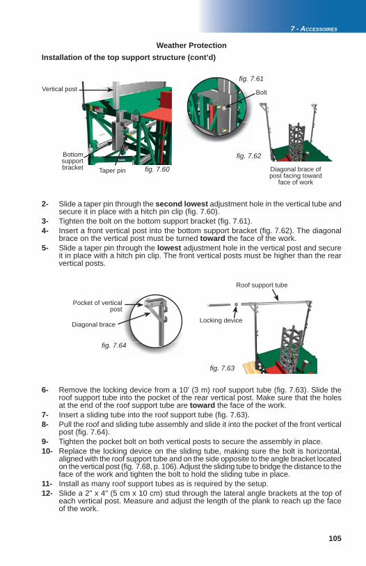
105
fi g. 7.60
fi g. 7.61
fi g. 7.62
fi g. 7.63
fi g. 7.64
7 - ACCESSOIRES
Weather ProtectionInstallation of the top support structure (cont’d)
Taper pin
BoltVertical post
Bottom support bracket Diagonal brace of
post facing toward face of work
Locking device
Roof support tube
Pocket of vertical post
Diagonal brace
2- Slide a taper pin through the second lowest adjustment hole in the vertical tube and secure it in place with a hitch pin clip (fi g. 7.60).3- Tighten the bolt on the bottom support bracket (fi g. 7.61).4- Insert a front vertical post into the bottom support bracket (fi g. 7.62). The diagonal brace on the vertical post must be turned toward the face of the work. 5- Slide a taper pin through the lowest adjustment hole in the vertical post and secure it in place with a hitch pin clip. The front vertical posts must be higher than the rear vertical posts.
6- Remove the locking device from a 10' (3 m) roof support tube (fi g. 7.63). Slide the roof support tube into the pocket of the rear vertical post. Make sure that the holes at the end of the roof support tube are toward the face of the work. 7- Insert a sliding tube into the roof support tube (fi g. 7.63). 8- Pull the roof and sliding tube assembly and slide it into the pocket of the front vertical post (fi g. 7.64).9- Tighten the pocket bolt on both vertical posts to secure the assembly in place.10- Replace the locking device on the sliding tube, making sure the bolt is horizontal, aligned with the roof support tube and on the side opposite to the angle bracket located on the vertical post (fi g. 7.68, p. 106). Adjust the sliding tube to bridge the distance to the face of the work and tighten the bolt to hold the sliding tube in place. 11- Install as many roof support tubes as is required by the setup. 12- Slide a 2" x 4" (5 cm x 10 cm) stud through the lateral angle brackets at the top of each vertical post. Measure and adjust the length of the plank to reach up the face of the work.

106
fi g. 7.65
fi g. 7.66
fi g. 7.67
fi g. 7.68
fi g. 7.70
fi g. 7.71
fi g. 7.72
fi g. 7.69
fi g. 7
fi g. 7.73
7 - ACCESSORIES
1- To install front bracing, slide 2" x 4" (5 cm x 10 cm) studs through the rear angle brackets located on the front vertical posts. Secure the studs in place using 1 1/2" (3,8 cm) nails or screws.
2- To install rear bracing, slide 2" x 4" (5 cm x 10 cm) studs through the top and bottom angle brackets located on the back of the rear vertical posts. Secure the studs in place using 1 1/2" (3,8 cm) nails or screws.
3- It is mandatory to install a diagonal brace every two bays. A bay could be left opened if there is diagonal bracing on both sides of the opening (fi g. 7.70).
Installation of bracing
Weather Protection
Installation of the top support structure (cont’d)
Lateral angle brackets
Bolt on locking device
Front angle bracket (located on the front end of
the sliding tube)
Rear angle brackets (located on the back of
vertical posts)
1- Install 2" x 4" (5 cm x 10 cm) studs in the angle brackets located at the front end of the sliding tubes, parallel to the face of the work. Secure the studs to the angle brackets with nails or screws.
2- Install 2" x 4" (5 cm x 10 cm) support studs at intervals on top of the roof section (fi g. 7.72). Make sure that no stud is installed over the locking devices and that the sliding tubes can be retracted if necessary. Secure the studs with nails or screws to the planks attached to the roof structure.
3- Install a tarp over the roof structure, using the studs to hold it in place.
Installation of the roof tarp
Front of unit
Back of unit
Diagonal brace
Roof tarp support studs
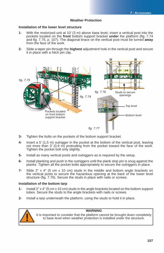
107
fi g. 7.74
fi g. 7.75
fi g. 7.76
fi g. 7.77
7 - ACCESSOIRES
Weather Protection
1- Install 2" x 4" (5 cm x 10 cm) studs in the angle brackets located on the bottom support tubes. Secure the studs to the angle brackets with nails or screws.
2- Install a tarp underneath the platform, using the studs to hold it in place.
Installation of the bottom tarp
1- With the motorized unit at 10' (3 m) above base level, insert a vertical post into the pockets located on the front bottom support bracket under the platform (fi g. 7.74 and fi g. 7.75, p. 107). The diagonal brace on the vertical post must be turned away from the face of the work.
2- Slide a taper pin through the highest adjustment hole in the vertical post and secure it in place with a hitch pin clip.
Installation of the lower level structure
Pockets located on front bottom support bracket
Studs to secure openings
3- Tighten the bolts on the pockets of the bottom support bracket.
4- Insert a 5' (1,5 m) outrigger in the pocket at the bottom of the vertical post, leaving not more than 3' (0,9 m) protruding from the pocket toward the face of the work. Tighten the pocket bolt only slightly.
5- Install as many vertical posts and outriggers as is required by the setup.
6- Install planking and push in the outriggers until the plank stop pin is snug against the planks. Tighten all the pocket bolts appropriately to secure the outriggers in place.
7- Slide 2" x 4" (5 cm x 10 cm) studs in the middle and bottom angle brackets on the vertical posts to secure the hazardous opening at the back of the lower level structure (fi g. 7.76). Secure the studs in place with nails or screws.
WARNINGIt is important to consider that the platform cannot be brought down completely
to base level when weather protection is installed under the structure.
Top level
Bottom level

108
fi g. 7.78
fi g. 7.79
7 - ACCESSORIES
Monorail
Installation of the support structure
8' (2,43 m)maximum4' (1,2 m)
maximum
(optional)
Installation of the monorail beam attachments1- Slide a monorail beam attachment assembly on a top support outrigger (fi g. 7.78) of the monorail structure. In a single unit installation, use the upper or lower tubes (fi g. 7.83) of the monorail attachment – using the same position throughout the installation. In a multiple units installation, use the lower tubes over the unit and
cantilever bridges and the upper tubes over the bearing bridge (fi g. 7.80).2- Secure the monorail beam attachment in place by tightening the pocket bolt.3- Loosen all four bolts on a monorail bracket (fi g. 7.78) to slacken the attachment plates on the bottom.
Distance between vertical supports
Monorail beam overhang
1- Follow steps 1 through 3 of the installation procedure for the bottom support structure on p. 104 for each bottom support tube required by the setup. The distance between two bottom supports must not exceed 8' (2,4 m), as shown in fi g. 7.78.2- Follow steps 1 through 5 of the installation procedure for the top support structure on p. 104 for each vertical post installation (front and back) required by the setup.3- Remove the locking device and the sliding tube from a 10' (3 m) outrigger and slide the outrigger into the pockets of the front and back vertical posts. Secure the outrigger in place by tightening the pocket bolts.4- Repeat step 3 for each 10' (3 m) outrigger required by the setup.
Using the same support structure as the weather protection system, the M2 Series monorail system allows loads of up to 1000 lb (454 kg) to be moved safely along the installation. The M2 Series monorail system can be used on setups with a maximum planking confi guration of three planks wide. It is recommended to refer to and comply with the monorail capacities tables on p. 109 before using a monorail installation. The weight of the monorail structure must also be deducted from the load capacities of the setup. Refer to the Load Capacities section on p. 80 to avoid overloading the platform.
Safety guidelines1- The use of a monorail is not allowed on a freestanding installation. For more information about tie levels for an installation with a monorail, refer to the Mast Tie Schedule on p. 70 of the Masts and Mast Ties section. 2- Before installing a monorail, it is important to refer to the general installation guidelines on p. 18 to select the appropriate method of installation for the confi guration.
Clearance area for passing tie levels
Top support outrigger
Stopper installed at each end of a beam installation
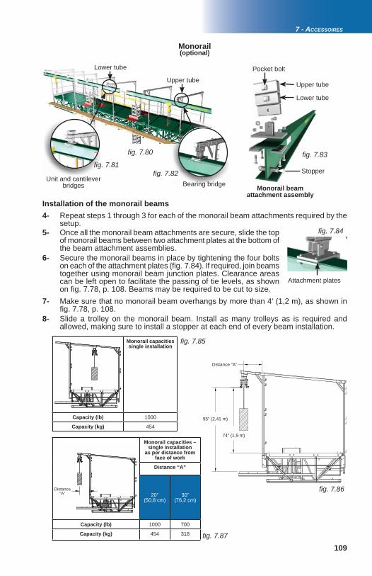
109
fi g. 7.80
fi g. 7.81 fi g. 7.82
fi g. 7.83
fi g. 7.84
fi g. 7.85
fi g. 7.86
fi g. 7.87
7 - ACCESSOIRES
Installation of the monorail beams
Monorail
Distance “A”
95" (2,41 m)
74" (1,9 m)
Monorail beam attachment assembly
Upper tube
Lower tube
(optional)
Monorail capacities – single installation
as per distance from face of work
Distance “A”
20"(50,8 cm)
30" (76,2 cm)
Capacity (lb) 1000 700
Capacity (kg) 454 318
Monorail capacitiessingle installation
Capacity (lb) 1000
Capacity (kg) 454
Distance “A”
Stopper
Pocket bolt
Unit and cantilever bridges Bearing bridge
Upper tube
Lower tube
Attachment plates
4- Repeat steps 1 through 3 for each of the monorail beam attachments required by the setup.5- Once all the monorail beam attachments are secure, slide the top of monorail beams between two attachment plates at the bottom of the beam attachment assemblies. 6- Secure the monorail beams in place by tightening the four bolts on each of the attachment plates (fi g. 7.84). If required, join beams together using monorail beam junction plates. Clearance areas can be left open to facilitate the passing of tie levels, as shown on fi g. 7.78, p. 108. Beams may be required to be cut to size.7- Make sure that no monorail beam overhangs by more than 4' (1,2 m), as shown in fi g. 7.78, p. 108.8- Slide a trolley on the monorail beam. Install as many trolleys as is required and allowed, making sure to install a stopper at each end of every beam installation.

110
fi g. 7.88 fi g. 7.89 fi g. 7.90
7 - ACCESSORIES
Flush Bearing Bridge Adapter(optional)
The optional fl ush bearing bridge adapter is used in a multiple units M2 Series installation to bring the bearing bridge structure at an even level with the motorized unit(s) and achieve a fl at deck platform. The fl ush bearing bridge adapter cannot be used to achieve an offset, angled or corner (inside or outside) bearing bridge installation. It is important to consider that the weight of the adapter (350 lb or 159 kg) must be deducted from the load capacities of the motorized unit.
Installation of the fl ush bearing bridge adapter1- Lift the top panel on the fl ush bearing bridge adapter. Align the adapter with the motorized unit. 2- Bolt the top part of the of the adapter to the top of the fi rst motorized unit using four 1" x 2" long (GR5) bolt assemblies through the four outer assembly sockets in the front and the back of the motorized unit. Do not tighten the bolt and nut assemblies yet.3- Attach the bottom part of the adapter to the bottom of the motorized unit using bridge link plates and pins sets (4) at the bearing bridge setting (fi g. 7.88 and fi g. 7.89). 4- Tighten the bolt assemblies (4) at the top of the adapter to 100 lb-ft (136 N-m).
Make sure to leave the top panel open.5- Repeat steps 1 through 5 to install an adapter on the second motorized unit.
Top panel of the adapter
B = Bearing bridge setting
Bridge link plate bearing setting
Positioning the fi rst motorized unit6- Prepare the fi rst motorized unit and the area where the setup will be installed as described in the general guidelines on p. 18 (steps 1 through 15). Make sure all base outriggers are properly confi gured according to the installation.Positioning the second motorized unit7- Determine the position of the second motorized unit. It is essential to make sure that the appropriate distance between the two motorized units is calculated precisely by measuring the length of the bearing bridge structure without any allocations for overlap.8- Prepare the second motorized unit and the area where it will be installed as described in the general guidelines on p. 18 (steps 1 through 15). Make sure all base outriggers are properly confi gured according to the installation.
The following installation steps must be carried out as part of a selected method of installation appropriate for the confi guration. For more information about setups and
confi gurations, refer to p. 18 of the Motorized Unit section.
WARNINGThe fl ush bearing bridge adapter cannot be used to achieve an offset,
angled or corner (inside or outside) bearing bridge installation.
9- Assemble the bearing bridge structure as required and allowed. Refer to steps 1 through 6 of the installation instructions for a bearing bridge structure, on p. 46 of the Bridges section.
Installation of the bearing bridge structure

111
fi g. 7.91
fi g. 7.92
fi g. 7.93
1
2
fi g. 7.94 fi g. 7.95
fi g. 7.96 3
7 - ACCESSOIRES
Flush bearing bridge adapter
Bearing bridge structure
Bearing bridge adapter properly hooked on fl ush bearing bridge
adapter
Flush Bearing Bridge Adapter(optional)
WARNINGIt is essential to make sure that the appropriate distance between the
two motorized units is calculated precisely by measuring the length of the bearing bridge structure without any allocations for overlap where a fl ush
bearing bridge adapter will be installed.
10- Using a rough terrain forklift or a crane, lift the bearing bridge assembly from the ground and lower it carefully between the two motorized units, making sure that the bearing bridge adapter is properly hooked on the fl ush bearing bridge adapter at each end.11- Close the top panel on each fl ush bearing bridge adapter and follow steps 12 to 14 of the installation instructions on p. 46 of the Bridges section to complete the installation of the bearing bridge. 12- Install the safety chains as described in step 10 of the installation instructions for a bearing bridge structure, on p. 47 of the Bridges section. 13- Proceed with the installation steps as described in the method of installation appropriate for the confi guration. For more information about methods of installation, refer to p. 18 of the Motorized Unit section.
Securing the Access WalkwayThe installation and use of some M2 Series applications, such as the sidewalk canopy and the mast base plates, will require that the access walkway be folded and locked in place. It is essential to proceed with extreme care to avoid any crushing hazard. 1- With the motorized unit at base level, slide an outrigger through the walkway over a bottom truss of the structure (see “1” in fi g. 7.93). 2- Using a U-bolt, secure the outrigger to the truss (see fi g. 7.94 and “2” in fi g. 7.93). 3- Use the chain to secure the access panel on the motorized unit to prevent use.
Installation of the bearing bridge structure (cont’d)
Access panelChain to secure

112
fi g. 7.97 fi g. 7.98
fi g. 7.99
fi g. 7.100
fi g. 7.101
fi g. 7.102
fi g. 7.103
7 - ACCESSORIES
Adapter Bases for Sidewalk Canopy Installation(optional)
Optional adapter bases for sidewalk canopy installation are used to install an M2 Series motorized unit at 10' (3 m) above the bearing surface, as part of a sidewalk canopy installation. The adapter bases for sidewalk canopy installation can be used in any single or multiple units M2 Series confi guration with mast ties. An M2 Series confi guration using adapter bases for a sidewalk canopy installation cannot be raised higher than 200' (61 m) above base level.
1- Before installing the adapter bases, determine where the cribbing and the jacks will rest. When required, appropriate cribbing must be placed under each screw jack on the legs of each support frame to distribute the load. Typically, for an installation without any planking, the support frames for the adapter bases will be installed at 8" (20 cm) from the face of the wall. Refer to p. 13 and p. 14 for the appropriate distance of installation between the two adapter bases. 2- The bearing surface under the adapter bases should be level, clear of debris and have a bearing capacity suffi cient to support the load under each screw jack. It is important to make sure that the bearing surface is stable and has not been subject to any type of erosion or deterioration caused by weather conditions (snow, rain, etc.).
Installation of the adapter bases
Adapter baseSupport frames
Screw jackScrew jack (4)
Retaining boltDO NOT
OVERTIGHTEN
To face of work
Adapter base frame
Rear jack
Front jack
X-brace
Support frame
Mast toggle bolt
Girder clamp assembly
74" (1,9 m)
91" (2,3 m)
g ( )
Minimum Bearing Surface CapacitiesInstallation with a Sidewalk Canopy
Height Load under each screw jack
(ft) (m) Reaction
50 15,28298 lb
3764 kg
75 22,98755 lb
3971 kg
100 30,59211 lb
4178 kg
150 45,710 123 lb
4592 kg
200 61,011 036 lb
5006 kg
Load reactions in the table above include a dynamic factor

113
fi g. 7.104
fi g. 7.105
7 - ACCESSOIRES
Adapter Bases for Sidewalk Canopy Installation(optional)
Installation of the adapter bases (cont’d)3- Mark the position of jacks. The distance between the front and rear jacks is 91" (2,3 m), while the distance between the left and right jacks is 74" (1,9 m) (fi g. 7.99, p. 112). 4- Using the supplied X-braces, assemble the two frames of the fi rst base support structure together. Verify the squareness of the assembly and make corrections, if necessary. 5- Loosen the retaining bolt on each leg of the frames (fi g. 7.98, p. 112) to release the screw jacks. 6- Repeat steps 3 to 5 for the second support structure. 7- Using a rough terrain forklift or a crane, lift and position the fi rst adapter base frame on top of one support assembly. Refer to the table in fi g. 7.104 to determine the distance between the mounting fl ange on the adapter base and the front edge of the support assembly. The adapter base frame will be moved back by 10" to 12" (25 cm to 30 cm) from the front edge of the support assembly for each plank required by the confi guration (as shown in fi g. 7.104). If necessary, install the support assembly further back from the face of the wall for larger planking confi gurations (see step 1 and fi g. 7.104). Use the Outrigger Selection table on p. 95 as a guide for planking confi gurations. 8- Secure the adapter base to the support assembly by tightening each girder clamp assembly (fi g. 7.102, p. 112) to a torque of 108 lb-ft (147 N-m).9- Verify the level of the adapter base and the support assembly. Adjust the level using the screw jacks on the support assembly or by adding cribbing. 10- Repeat steps 7 through 9 for the second adapter base.
WARNINGOnce the unit is installed on the adapter base, it is mandatory to install the fi rst two tie levels on both masts before proceeding with the installation.
Unit on adapter base for sidewalk canopy installation with three-plank confi guration
Three-tie system required for fi rst two tie levels on both masts
Unit must be held up by a crane or rough terrain forklift during installation until fi rst two tie levels are installed on both masts
Number of planks Distance “D”
0 14" (36 cm)1 24" (61 cm)2 34" (86 cm)3 44" (112 cm)
8" (20 cm)
Distance “D” in the above table is based on a 8" (20,3 cm) clearance between the support structure and the face of work, with a 10" (25 cm) wide planking confi guration.

114
7 - ACCESSORIES
Adapter Bases for Sidewalk Canopy Installation(optional)
Installation of the motorized unit11- On each mast on the motorized unit, make sure that there are two mast sections installed on each mast (fi g. 7.102) in addition to the mast sections welded on the base.12- Before lifting and moving the motorized unit, make sure all workers have stepped down, that all tools, equipment and loads have been removed from the platform and that the mast locking bars are in place. Fold and lock the access walkway, as described in the instructions on p. 111. 13- Raise the motorized unit up to the second mast sections until it is above the mast toggle bolts.14- Using a rough terrain forklift or a crane, support the motorized unit. Refer to p. 37 ofthe Motorized Unit section for instructions on the lifting of a motorized unit. Loosen and fl ip down the mast toggle bolts joining the lowest mast sections to the mast sections welded on the base. 15- Lift and carefully lower the motorized unit on top of the adapter bases. 16- Continue to hold the motorized unit and secure it to the adapter bases with the mast toggle bolts located on the adapter bases. Tighten all bolts to 120 lb-ft (163 N-m) of torque, using a cross-pattern sequence when tightening. Remove the mast locking bars. 17- Still holding the motorized unit, install two tie levels to tie the masts to the face of the work. It is important to use a three-tie system for the fi rst two tie levels. Refer to p. 70 of the Masts and Mast Ties section for instructions on how and when to install mast ties. 18- Once the fi rst two tie levels are installed, make sure that hooks are properly engaged on a mast rung on both masts and release the unit. Proceed with the installation steps as described in the method of installation appropriate for the confi guration. For more information about methods of installation, refer to p. 18 of the Motorized Unit section.Dismantling guidelines 1- Make sure all the equipment necessary for a safe dismantlement of the installation is on hand (slings, chains, crane or rough terrain forklift, etc.). Make sure the regular motorized unit base is also on hand. 2- Follow the dismantling instructions appropriate for the confi guration leaving the last two tie levels in place. For dismantling instructions, refer to the Motorized Unit section, starting on p. 32. 3- Before lifting and moving the motorized unit, make sure all workers have stepped down, that all tools, equipment and loads have been removed from the platform and that the mast locking bars are in place. 4- Using a rough terrain forklift or a crane, support the motorized unit. Refer to p. 37 of the Motorized Unit section for instructions on the lifting of a motorized unit. Remove the last two tie levels on each mast. Make sure that the motorized unit remains on the second mast sections, above the mast toggle bolts joining them to the fi rst mast sections installed. 5- Still holding the motorized unit, loosen all toggle bolts and clamps holding the unit to the adapter bases. 6- To ensure proper stability, make sure that the regular base is level. Carefully lift the motorized unit off the sidewalk canopy frames and lower it on top of the regular base. 7- Continue to hold the unit and secure it to the base by tightening all bolts to 120 lb-ft (163 N-m) of torque, using a cross-pattern sequence when tightening. 8- Once the base is secured, make sure that hooks are properly engaged on a mast rung on both masts and release the motorized unit.9- Remove the adapter bases from the support assemblies.

115
fi g. 7.106
fi g. 7.107
fi g. 7.108
7 - ACCESSOIRES
Adapter Bases for Sidewalk Canopy Installation(optional)
Mast Base Plates(optional)
Optional mast base plates are used to install an M2 Series motorized unit in areas where space is restricted around the base. The mast base plates can be used in any single or multiple units M2 Series confi guration with mast ties.
1- Before installing the mast base plates, determine where the cribbing will rest. The bearing surface under the cribbing should be level, clear of debris and have the proper bearing capacity. Refer to the Minimum Bearing Surface Capacities for an Installation with Mast Base Plates table, fi g. 7.108 for guidance. Should the actual bearing capacity be inferior to the values in the table, please seek instructions and recommendations from Hydro Mobile.
Installation
WARNINGOn an installation where the unit is not on its regular base and is on adapter bases or mast base plates, it is mandatory to use a three-tie system for
the fi rst two tie levels.
Dismantling guidelines (cont’d)10- Remove the mast locking bars and lower the motorized unit to base level.11- Unlock the access walkway and remove the additional mast sections installed on each mast of the unit.12- Remove the X-braces and disassemble the support assemblies.13- If the unit is to be stored for any signifi cant length of time, refer to p. 118 of the Transport, Storage and Maintenance section for instructions on how to properly store an M2 Series motorized unit.
Mast base plate
Mast toggle bolt
Minimum Bearing Surface CapacitiesInstallation with a Mast Base Plate
Height Load under each mast
(ft) (m) Reaction
50 15,222 735 lb
10 312 kg
75 22,923 985 lb
10 879 kg
100 30,525 235 lb
11 446 kg
150 45,727 735 lb12 580 kg
200 61,030 235 lb
13 714 kg
250 76,232 735 lb
14 848 kg
Access walkway folded
and secured
Load reactions in the table above include a dynamic factor
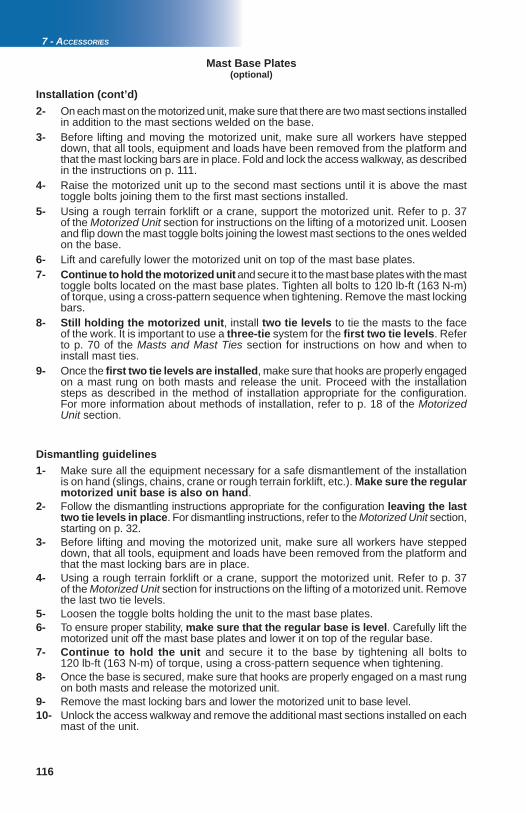
116
7 - ACCESSORIES
2- On each mast on the motorized unit, make sure that there are two mast sections installed in addition to the mast sections welded on the base.3- Before lifting and moving the motorized unit, make sure all workers have stepped down, that all tools, equipment and loads have been removed from the platform and that the mast locking bars are in place. Fold and lock the access walkway, as described in the instructions on p. 111. 4- Raise the motorized unit up to the second mast sections until it is above the mast toggle bolts joining them to the fi rst mast sections installed.5- Using a rough terrain forklift or a crane, support the motorized unit. Refer to p. 37 of the Motorized Unit section for instructions on the lifting of a motorized unit. Loosen and fl ip down the mast toggle bolts joining the lowest mast sections to the ones welded on the base. 6- Lift and carefully lower the motorized unit on top of the mast base plates. 7- Continue to hold the motorized unit and secure it to the mast base plates with the mast toggle bolts located on the mast base plates. Tighten all bolts to 120 lb-ft (163 N-m) of torque, using a cross-pattern sequence when tightening. Remove the mast locking bars. 8- Still holding the motorized unit, install two tie levels to tie the masts to the face of the work. It is important to use a three-tie system for the fi rst two tie levels. Refer to p. 70 of the Masts and Mast Ties section for instructions on how and when to install mast ties. 9- Once the fi rst two tie levels are installed, make sure that hooks are properly engaged on a mast rung on both masts and release the unit. Proceed with the installation steps as described in the method of installation appropriate for the confi guration. For more information about methods of installation, refer to p. 18 of the Motorized Unit section.
Mast Base Plates(optional)
Installation (cont’d)
1- Make sure all the equipment necessary for a safe dismantlement of the installation is on hand (slings, chains, crane or rough terrain forklift, etc.). Make sure the regular motorized unit base is also on hand. 2- Follow the dismantling instructions appropriate for the confi guration leaving the last two tie levels in place. For dismantling instructions, refer to the Motorized Unit section, starting on p. 32.3- Before lifting and moving the motorized unit, make sure all workers have stepped down, that all tools, equipment and loads have been removed from the platform and that the mast locking bars are in place. 4- Using a rough terrain forklift or a crane, support the motorized unit. Refer to p. 37 of the Motorized Unit section for instructions on the lifting of a motorized unit. Remove the last two tie levels. 5- Loosen the toggle bolts holding the unit to the mast base plates.6- To ensure proper stability, make sure that the regular base is level. Carefully lift the motorized unit off the mast base plates and lower it on top of the regular base. 7- Continue to hold the unit and secure it to the base by tightening all bolts to 120 lb-ft (163 N-m) of torque, using a cross-pattern sequence when tightening. 8- Once the base is secured, make sure that hooks are properly engaged on a mast rung on both masts and release the motorized unit. 9- Remove the mast locking bars and lower the motorized unit to base level.10- Unlock the access walkway and remove the additional mast sections installed on each mast of the unit.
Dismantling guidelines

117
fi g. 7.109
fi g. 7.110
fi g. 7.111
7 - ACCESSOIRES
Mast Base Plates(optional)
Dismantling guidelines (cont’d)11- If the unit is to be stored for any signifi cant length of time, refer to p. 118 of the Transport, Storage and Maintenance section for instructions on how to properly store an M2 Series motorized unit.
Multiple Mast Handler(optional)
The use of the multiple mast handler will allow the qualifi ed erector/dismantler to install pre-assembled lengths of mast (also referred to as "sticks") and reduce the time required to achieve the installation of the setup.
1- Pre-assemble a length of mast sections on the ground. Mast sections must be laid down horizontally on the ground. For instructions on the assembly of mast sections, refer to p. 69 of the Masts and Mast Ties section. Tighten all bolts to 120 lb-ft (163 N-m). The length of pre-assembled mast allowed will be equal to the authorized height in feet (meters) between two tie levels for the confi guration, according to the selected method of installation and the mast tie schedule specifi c to that method of installation. For more information about methods of installation, refer to p. 18 of the Motorized Unit section. Refer also to the Mast Tie Schedule on p. 70 for information about distances between tie levels.
Installation
Highest step of lowest
mast section
Max
imum
leng
th e
qual
to a
utho
rized
hei
ght
betw
een
two
tie le
vels
2- Install the mast handler on the highest step of the lowest mast section of the pre-assembled length of mast (fi g. 7.109).
It is important to consider the weight of the pre-assembled length of mast that must be lifted and to make sure to select a sling, chain or cable that can lift that weight. For example, a pre-assembled 30' (9,1 m) length of mast sections will weigh 1410 lb (640 kg). 3- Insert the sling (or chain or cable) through the pre-assembled length of mast and attach the hook to the shackle on the mast handler.4- Using a crane (or a forklift), carefully lift and lower the pre-assembled length of mast on top of the last mast section installed. 5- Still holding the length of mast, attach the bottom mast section to the top of the mast section already installed. For instructions on the assembly of mast sections, refer to p. 69 of the Masts and Mast Ties section. Tighten all bolts to 120 lb-ft (163 N-m).6- Remove the shackle from the mast handler to release the hook and sling.7- Remove the mast handler from the mast section. 8- Raise the motorized unit on the newly added length of mast and install the next tie level. 9- Repeat steps 2 to 8 for each pre-assembled length of mast to install, as required and allowed.
Sling attached to shackle on mast handler
Mast handler shown in red for illustration purposes only

118
fi g. 8.1
fi g. 8.2
fi g. 8.3
fi g. 8.4
8 - TRANSPORT, STORAGE AND MAINTENANCE
Transport and StoragePreparation of the motorized unit for transport
1- Dismantle the motorized unit setup following the appropriate guidelines. For any standard confi guration using a motorized unit with its regular base, follow the dismantling guidelines starting on p. 32 of the Motorized Unit section. For a setup equipped with adapter bases for a sidewalk canopy installation, refer to p. 114 for the appropriate dismantling instructions. Refer to the dismantling guidelines on p. 116 for a setup using mast base plates.
2- Once the setup has been dismantled and the unit is at base level, turn off the engine. The choke handle must not be used to shut down the engine.
3- Open the engine access panel and move the engine gasoline valve lever to the OFF position.
4- Store the control post.
5- Remove the cylinder and secondary hooks.
6- Install the transport hook and store the cylinder and secondary hooks in their storage location.
7- Retrieve the mast locking bar from its storage location and insert it into the mast. Refer to p. 62 of the Power Pack and Operating Components for instructions on the storage of locking bars.
8- Repeat steps 5 through 7 on the other mast.
9- Remove the plank-end guardrails and store them in their storage location.
ne.
Gas lever
Mast locking bar Transport hook
Hooks in their storage location
fi 8 3
Storage location for plank-end guardrails
Storage location for end guardrails

119
fi g. 8.5
fi g. 8.6
fi g. 8.7
fi g. 8.8
8 - TRANSPORT, STORAGE AND MAINTENANCE
Transport and StoragePreparation of the motorized unit for transport
10- Remove the end guardrails with the end guardrail pockets and store them in their storage location.
11- Remove the sliding doors and temporarily store them on the deck of the unit.
12- Remove the door support guardrails and store them in their storage location.
13- Store the sliding doors with the rest of the guardrails.
14- Once all guardrails are stored and secured, lower the jacks completely (fi g. 8.8).
15- Refer to p. 37 of the Motorized Unit section for more information on the lifting and transport of a motorized unit.
WARNINGBefore transporting or storing a motorized unit, make sure that the gasoline
valve lever has been turned OFF. Disconnect the battery if the motorized unit is to be stored for any signifi cant length of time.
fig 8 5
Temporarily store sliding doors on the deck of the unit
55
t lidi
fi g. 8.6
fi g. 8.7
fi g. 8.8
Storage of the motorized unit1- Inspect the structure of the motorized unit for any sign of damage or distortion. Clean the motorized unit thoroughly to limit the effects of any corrosive agent. 2- Prepare the motorized unit as described in the preparation steps on p. 118. If the motorized unit is to be stored for any signifi cant length of time, disconnect the battery. 3- Before storing the motorized unit, make sure to place suffi cient cribbing under the base to prevent damages to the bottom of the structure. 4- Choose an appropriate storage location. Avoid storing the motorized unit in a location with direct exposure to aggressive or corrosive materials in the surroundings.
1- Inspect the structure of the bridge, including the inside of the open-end tubes, for any sign of damage or distortion. Clean the bridge and its components thoroughly to limit the effects of any corrosive agent.
Storage of a bridge

120
fi g. 8.9
8 - TRANSPORT, STORAGE AND MAINTENANCE
Inspections and Maintenance Proper maintenance and service will warrant safe, economical, and trouble-free operation of an M2 Series motorized unit and its accessories. In order to ensure operational safety and avoid failures, the owner must make sure that all the scheduled inspection and maintenance operations have been effectively and timely carried out according to the inspection and maintenance schedules recommended for M2 Series motorized units and their accessories. Blank copies of the daily inspection checklist must be available on job sites at all times to be fi lled out when daily and weekly inspection operations are carried out. Maintenance and inspection logs must be kept on record for warranty and safety purposes. Copies of all maintenance and inspection checklists can be obtained by contacting the distributor/service center or the Hydro Mobile technical support team or downloaded directly from the Hydro Mobile website at www.hydro-mobile.com.
Inspection and maintenance of the cylinder hook To ensure safe and trouble-free operation of the cylinder hook, it is mandatory to inspect it as per the maintenance schedule. A worn rubber must be replaced immediately, before operating the motorized unit. A worn and defective rubber will prevent the cylinder hook from working correctly and engage properly on mast rungs.
Daily and Weekly Inspections and Maintenance Each Hydro Mobile motorized unit and its accessories must be submitted to daily (or before every working shift) and weekly inspections and maintenance operations performed by the qualifi ed operator. For more information about a qualifi ed operator, refer to p. 5 of the Motorized Unit section.Daily and weekly inspection operations are only necessary when the motorized unit and its accessories are in use. The owner and/or user is responsible for all inspection and maintenance operations. Before being fi rst used on a job site, an M2 Series motorized unit and its accessories must be inspected effectively and timely, according to the schedules recommended for M2 Series motorized units and their accessories.Maintenance and inspection logs must be kept on record for warranty and safety purposes. Blank copies of the daily inspection checklist must be available on job sites at all times to be fi lled out when daily and weekly inspection operations are carried out. The notes and comments form must be used to indicate any discrepancy or any item found to be not acceptable. Any discrepancy must be reported to the owner/user and appropriate corrective action must be taken immediately. Corrective actions must be performed by qualifi ed personnel.
1- Hold the cylinder fi rmly (fi g. 8.9) and pull the hook all the way back.
2- Let go of the hook and verify its position.
Hold cylinder here
Pull back here
Direction of pull
Transport and StorageStorage of a bridge
2- Bridges must not be stored directly on the ground. Make sure to place suffi cient cribbing under the bottom chords to prevent damages to the bottom of the structure. 3- Avoid storing the bridge in a location with direct exposure to aggressive or corrosive materials in the surroundings.

121
CAUTION / ATTENTION / CUIDADO
A0800000-0028
PROLAB GS-1000ONLY – SEULEMENT – SOLAMENTE
fi g. 8.10
fi g. 8.11
fi g. 8.12
fi g. 8.13 fi g. 8.14
fi g. 8.15
8 - TRANSPORT, STORAGE AND MAINTENANCE
Inspections and MaintenanceDaily and Weekly Inspections and Maintenance
Inspection and maintenance of the cylinder hook (cont’d)
3- The hook must not lean towards or away from the mast, but stand up straight as in “B” in fi g. 8.10. If the position of the hook is as in “A” or “C” in fi g. 8.10, the rubber must be replaced immediately.
B CACorrectIncorrect Incorrect
Hook in idle position
1- Remove the linch pin and slide out the clevis pin (GR8) (fi g. 8.11). Lift the hook from the cylinder.2- Remove the defective rubber.3- Cut slight beveled edges lengthwise on the replacement rubber (see fi g. 8.12) so that it fi ts snugly against the welding tracks at the bottom of the pocket. 4- Insert the replacement rubber in the top part of the cylinder. Slide in the hook and verify that the holes in the hook and the holes in the top part of the cylinder align properly, with no more than 1/16" to 1/8" (1,6 mm to 3,2 mm) of play. The rubber must be lightly compressed. Trim the bottom part of the rubber until the holes align correctly. 5- Once the rubber fi ts correctly, replace the hook and secure it in place with the clevis and linch pins. 6- Test the operation of the cylinder hook as described in steps 1 through 3 of the inspection instructions.
g. 8.11
Clevis pin (GR8)
Linch pin
Beveled edge
Cut Cut
Cut beveled edges on the replacement rubber only deep
enough for fi tting
Rubber
Replacement of the rubber of the cylinder hook
Greasing the mast carriage guide rollersTo ensure safe and trouble-free operation, it is mandatory to grease each mast carriage roller (32) as part of the weekly inspection and maintenance operations. A proper greasing will extend the life expectancy of the rollers. Rollers shown in red in fi g. 8.14 must be greased using only Prolab GS1000 grease.
Rollers are shown in red for illustration purposes only
Grease must be applied here on each roller (32)

122
fi g. 8.16
fi g. 8.17
fi g. 8.18
8 - TRANSPORT, STORAGE AND MAINTENANCE
Inspecting and greasing the safety hooksThe safety hooks are an important part of the safety mechanism of the M2 Series mast climber and must be able to move freely at all times and be in appropriate working condition. To ensure the proper operation of safety hooks, they must be inspected and greased as part of the weekly inspection and maintenance operations.
1- Inspect each safety hook (4) to make sure that there is no sign of engagement. If there are signs of an engagement, each safety hook must be thoroughly inspected by a qualifi ed technician. It is mandatory to replace any triggered safety hook and its pivot bolt immediately before resuming operation of the unit. The replacement of a safety hook must be performed by the qualifi ed technician. For information about qualifi ed technicians, refer to p. 5 of the Motorized Unit section.
2- Inspect each safety hook to make sure that there is no indication of excessive grease. If there are signs of excessive grease, a qualifi ed technician must take the safety hook apart and clean it properly.
3- Apply grease to each safety hook (4) as part of the weekly inspection and maintenance operation. Safety hooks must be greased using only Prolab GS1000 grease.
Safety hooks are shown in red for illustration purposes only
Grease must be applied here on each safety
hook (4)
Any triggered safety hook and its pivot
bolt must be replaced immediately before
resuming operation of the unit
Triggered safety hook
Pivot bolt
Inspections and MaintenanceDaily and Weekly Inspections and Maintenance

123
8 - TRANSPORT, STORAGE AND MAINTENANCE
Frequent inspections must be performed by a qualifi ed technician. For more information about qualifi ed technicians, refer to p. 5 of the Motorized Unit section.
Frequent Inspections and Maintenance
Each Hydro Mobile motorized unit must be submitted to a frequent inspection performed every three months by a qualifi ed technician.
Maintenance and inspection logs must be kept on record for warranty and safety purposes. Blank copies of the frequent inspection checklist must be fi lled out when frequent inspection operations are carried out. The notes and comments form must be used to indicate any discrepancy or any item found to be not acceptable. Any discrepancy must be reported to the owner/user and appropriate corrective action must be taken immediately. Corrective actions must be performed by a qualifi ed technician. For more information about qualifi ed technicians, refer to p. 5 of the Motorized Unit section.
All inspection and maintenance steps included in the daily inspection checklist must be performed before the frequent inspection and maintenance steps.
It is recommended to use replacement parts manufactured by or recommended by Hydro Mobile. The use of substitute parts could not only void the warranty covering this motorized unit and its components but cause serious damages that could lead to injury or death. It is recommended to replenish and grease components only with fl uids and lubricants recommended by Hydro Mobile.
Inspections and Maintenance
Annual Inspections and Maintenance
Annual inspections must be performed by a qualifi ed technician. For more information about qualifi ed technicians, refer to p. 5 of the Motorized Unit section.
Each Hydro Mobile motorized unit must be submitted to an annual inspection performed by a qualifi ed technician. This annual inspection must be carried out no later than 13 months after the previous annual inspection.
Maintenance and inspection logs must be kept on record for warranty and safety purposes. Blank copies of the annual inspection checklist must be fi lled out when annual inspection operations are carried out. The notes and comments form must be used to indicate any discrepancy or any item found to be not acceptable. Any discrepancy must be reported to the owner/user and appropriate corrective action must be taken immediately. Corrective actions must be performed by a qualifi ed technician. For more information about qualifi ed technicians, refer to p. 5 of the Motorized Unit section.
It is recommended to use replacement parts manufactured by or recommended by Hydro Mobile. The use of substitute parts could not only void the warranty covering this motorized unit and its components but cause serious damages that could lead to injury or death. It is recommended to replenish and grease components only with fl uids and lubricants recommended by Hydro Mobile.

124
fi g. 8.19 fi g. 8.20 fi g. 8.21
fi g. 8.22 fi g. 8.23
8 - TRANSPORT, STORAGE AND MAINTENANCE
Copies of inspection and maintenance checklists shown below can be obtained by contacting the distributor/service center or the Hydro Mobile technical support team or downloaded directly from the Hydro Mobile website at www.hydro-mobile.com.
Inspections and Maintenance
WEEK1USE CHECK MARK FOR EACH ENTRY VERIFIED. IF NECESSARY, TAKE CORRECTIVE ACTION BEFORE INSERTING CHECK MARK.
PROJECT: COMPETENT PERSON (full name):
Each Hydro Mobile motorized unit and its accessories must be inspected daily or before every working shift, as well as weekly. Use the spaces below to monitor 6 days of the daily and weekly inspections of an M2 Series motorized unit and its accessories. Use the Notes and Comments form to indicate any discrepancy or any item found to be not acceptable. Any discrepancy must be reported and appropriate corrective action must be taken immediately. Corrective actions must be performed by qualified personnel.
LOCATION:
CONTRACTOR:
MOTORIZED UNIT SERIAL NUMBER:
DATE (WEEK OF):
2 3 4 5
DAILY INSPECTION CHECKLISTM2 SERIESMOTORIZED UNITS and ACCESSORIES
SERIAL NUMBER (if applicable):ACCESS and SAFETYAll access panels are clear of material and equipment.
All safety guardrails are in position and doors are operational (no fall hazard).
An evacuation plan specific to the job site is available to all workers and a legible copy of the owner’s manual is in the tool box.
Construction traffic is controlled on and around job site (proper barriers installed).
If the work platform is accessed from inside the building or off a scaffold stair tower, transfer is safe and free from obstruction.
Mast climbing is not impeded in any way and access walkway is clear of debris and working properly.
Minimum clearance from overhead power lines is maintained according to local regulation.
On special façade shapes, cross box kits, face guardrails and plank guardrails are properly installed and secure.
Perimeter of setup is safe and delimited (warning tape, concrete blocks).
Setup and installation meet the requirements prescribed by owner’s manual or approved engineering drawing.
The platform clears all obstacles (building, balconies, etc.) and can be raised or lowered.
Work and circulation areas on the platform are clear of any obstruction.
SERIAL NUMBER (if applicable):BASEBase is level and cribbing under jacks has not moved.
SERIAL NUMBER (if applicable):MOTORIZED UNIT – COMPONENTSCables and control levers have been verified and are functioning properly.
Each cylinder hook, secondary hook and lowering cam is in good condition and functioning properly.
Each cylinder, hydraulic hose and hydraulic component is free of leaks and signs of wear.
Each roller has been greased using Prolab GS1000 #28840 only. (WEEKLY)
Each roller has been verified and is in good condition.
Gasoline and engine oil levels are appropriate or have been replenished. Air filter has been verified and is in good condition or has been replaced, if necessary.
Hydraulic oil level has been verified and hydraulic tank has been replenished, if required, with oil recommended by Hydro Mobile.
Lifting mechanism is clear of debris (mortar, masonry material, etc.) and shows no signs of excessive wear.
Motorized unit structure has been inspected and shows no signs of damage or distortion.
On an electrical unit, the power cable has been inspected and shows no signs of damage. Input power is adequate and phases are in sync.
On an electrical unit, the routing of the power cable is free from obstruction and the cable recoils properly.
Rubber on each cylinder hook has been verified as described in Owner’s manual procedure and is in good condition.
SERIAL NUMBER (if applicable):MOTORIZED UNIT – SAFETY DEVICESEach backup safety hook has been inspected and shows no sign of engagement prior to inspection. Each safety hook is clean and can move freely. Motorized unit must be put out of service if any safety hook is found to be defective or shows signs of having been engaged previously.
SERIAL NUMBER (if applicable):MASTS and MAST TIESMast bolts are tightened at the proper torque (120 lb-ft or 163 N-m). Mast bolt washers have been replaced if bent. (WEEKLY)
Mast sections have been inspected and show no signs of damage or distortion.
Page 1 of 2M2_MAINTDAILY_1014
M2 SERIESMOTORIZED UNITS and ACCESSORIES FREQUENT INSPECTION CHECKLIST
AUTHORIZED DEALER NAME and ADDRESS: USER/OWNER NAME and ADDRESS:
NAME of AUTHORIZED TECHNICIAN: MOTORIZED UNIT MODEL and SERIAL NUMBER: DATE of INSPECTION:
Each Hydro Mobile motorized unit and its accessories must be submitted to a frequent inspection. Use the spaces below to monitor inspections that need to be performed every three months. Use the Notes and Comments form to indicate any discrepancy or any item found to be not acceptable. Any discrepancy must be reported and appropriate corrective action must be taken immediately. Corrective actions must be performed by a technician certified specifically for M2 Series motorized units and their accessories. All inspection steps included in the daily inspection checklist must be performed before the frequent inspection steps.It is recommended to use replacement parts manufactured by or recommended by Hydro Mobile. The use of substitution parts could not only void the warranty covering this motorized unit and its components but cause serious damages that could lead to injury or death. It is recommended to replenish and grease components only with fluids and lubricants recommended by Hydro Mobile.
Frequent inspections must be performed by a technician specifically certified for M2 Series motorized units and their accessories. USE CHECK MARK FOR EACH ENTRY VERIFIED. IF NECESSARY, TAKE CORRECTIVE ACTION BEFORE INSERTING CHECK MARK. OK CORRECTED N/A
SERIAL NUMBER (if applicable):BASECheck condition of outriggers (4x) and outrigger shims.
Check squareness and alignment of the base as per technical procedure.
Inspect base outriggers for any welding defects, damaged parts and excessive rust or corrosion.
Inspect base structure for any welding defects, damaged parts or excessive rust or corrosion (LEFT).
Inspect base structure for any welding defects, damaged parts or excessive rust or corrosion (RIGHT).
Inspect center beam for any welding defects, damaged parts or excessive rust or corrosion.
Inspect jack (4x or 8x, as applicable) gears and mechanism. Grease jack mechanism, if necessary.
SERIAL NUMBER (if applicable):MOTORIZED UNIT STRUCTURECheck integrity of engine access panel.
Check integrity of mast tie door and hinges (LEFT).
Check integrity of mast tie door and hinges (RIGHT).
Check integrity of walkway access door, hinges and locking mechanism.
Check motorized unit structure for any welding defects, damaged parts or excessive rust or corrosion, and any sign of distortion.
SERIAL NUMBER (if applicable):ACCESS WALKWAY and COMPONENTSCheck access walkway structure for any welding defects, damaged parts or excessive rust or corrosion.
Check condition of safety straps.
SERIAL NUMBER (if applicable):GAS ENGINEPerform recommended maintenance on Honda engine as per instructions in Honda owner’s manual.
SERIAL NUMBER (if applicable):POWER PACK and HYDRAULIC COMPONENTSAdjust engine RPM at full throttle and idle speed as per technical procedure.
Check all hydraulic hoses and fittings for any leaks or signs of wear.
Check choke actuation.
Check condition and adjustment of hydraulic control cable.
Check condition and adjustment of hydraulic control lever.
Check condition of the hydraulic return filter and replace, if necessary.
Check electrical connection to the engine starter switch.
Check electrical wiring and connections.
Check engine control rods.
Page 1 of 3M2_MAINTFREQ_1014
M2 SERIESMOTORIZED UNITS and ACCESSORIES ANNUAL INSPECTION CHECKLIST
AUTHORIZED DEALER NAME and ADDRESS: USER/OWNER NAME and ADDRESS:
NAME of AUTHORIZED TECHNICIAN: MOTORIZED UNIT MODEL and SERIAL NUMBER: DATE of INSPECTION:
Each Hydro Mobile motorized unit and its accessories must be submitted to an annual inspection. Use the spaces below to monitor inspections that need to be performed every year. Use the Notes and Comments form to indicate any discrepancy or any item found to be not acceptable. Any discrepancy must be reported and appropriate corrective action must be taken immediately. Corrective actions must be performed by a technician certified specifically for M2 Series motorized units and their accessories. It is recommended to use replacement parts manufactured by or recommended by Hydro Mobile. The use of substitution parts could not only void the warranty covering this motorized unit and its components but cause serious damages that could lead to injury or death. It is recommended to replenish and grease components only with fluids and lubricants recommended by Hydro Mobile.
Annual inspections must be performed by a technician specifically certified for M2 Series motorized units and their accessories. USE CHECK MARK FOR EACH ENTRY VERIFIED. IF NECESSARY, TAKE CORRECTIVE ACTION BEFORE INSERTING CHECK MARK. OK CORRECTED N/A
SERIAL NUMBER (if applicable):BASECheck condition of outriggers (4x) and outrigger shims.
Check squareness and alignment of the base as per technical procedure.
Inspect base outriggers for any welding defects, damaged parts and excessive rust or corrosion.
Inspect base structure for any welding defects, damaged parts or excessive rust or corrosion (RIGHT).
Inspect base structure for any welding defects, damaged parts or excessive rust or corrosion (LEFT).
Inspect center beam for any welding defects, damaged parts or excessive rust or corrosion.
Inspect jack (4x or 8x, as applicable) gears and mechanism. Grease jack mechanism, if necessary.
SERIAL NUMBER (if applicable):MOTORIZED UNIT STRUCTURECheck integrity of engine access panel.
Check integrity of mast tie door and hinges (LEFT).
Check integrity of mast tie door and hinges (RIGHT).
Check integrity of walkway access door, hinges and locking mechanism.
Check motorized unit structure for any welding defects, damaged parts or excessive rust or corrosion, and any sign of distortion.
SERIAL NUMBER (if applicable):ACCESS WALKWAY and COMPONENTSCheck access walkway structure for any welding defects, damaged parts or excessive rust or corrosion.
Check condition of safety straps.
SERIAL NUMBER (if applicable):GAS ENGINEPerform recommended maintenance on Honda engine as per instructions in Honda owner’s manual.
SERIAL NUMBER (if applicable):POWER PACK and HYDRAULIC COMPONENTSAdjust engine RPM at full throttle and idle speed as per technical procedure.
Check all hydraulic hoses and fittings for any leaks or signs of wear.
Check choke actuation.
Check condition and adjustment of hydraulic control cable.
Check condition and adjustment of hydraulic control lever.
Check electrical connection to the engine starter switch.
Check electrical wiring and connections.
Check engine control rods.
Check gasoline level. Replenish, if necessary.
Page 1 of 3M2_MAINTANNUAL_1014
Copies of the job survey checklist and the handover checklist shown below can be obtained by contacting the distributor/service center or the Hydro Mobile technical support team or downloaded directly from the Hydro Mobile website at www.hydro-mobile.com.
Daily inspection checklist Frequent inspection checklist Annual inspection checklist
F300 – 460VF200 – 460VF300 – 600VF200 – 600V
F300 – 460VF200 – 460VF300 – 600VF200 – 600V
240V400V
230V400V
Power packbridge
24' (7,3 m)14' (4,3 m)
Crane available for Erecting Repositioning Dismantling Loading / unloading
Forklift available for Erecting Repositioning Dismantling Loading / unloadingInstallation to be erected / dismantled by Hydro Mobile Hydro Rents Dealer
Installation to be erected / dismantled by user User installers are appropriately qualifi ed YES NO
Erector / dismantler training required YES NO User / operator training required YES NO
Number of E&D training attendees Number of U/O training attendees
JOB SURVEY – JOB HAZARD ANALYSISProject Name: Date:
Series to be used for projectELECTRIC-POWERED GAS-POWERED TRANSPORT PLATFORM
Project address
City State/Province
Estimated start date Estimated duration WEEKS
Company Contact
Address Contact phone
Contact email
City Notes
State/Province Zip/Postal code
Phone Fax
General contractor Contact
Phone Contact phone
Brick Roofi ng
Block / stone Material only
Stucco Personnel / material
Glazing Other
Scope of workSteel frame Wood frame
Concrete Post tension cables
psi Balcony slab
Load bearing masonry Other
(specify)
Building / structure details
Height of building FTM Number of bearing bridges
Number of motor units Maximum cantilever length FTM
Number of repositions Outrigger support
Number of hoists Length of planking FTM
Number of swivel bridges Number of MPIs or planked corner returns
Required capacity LBKG Counterweight required
Total mast height FTM Number of ties per mast (if tied)
Distance between tie levels FTM Type of anchors (if tied)
Height of fi rst tie level FTM Max travel distance above last tie level MAST(S)
Available services and training levels
HMJAJHA0315
F300 – 480VF200 – 480VF300 – 600VF200 – 600V
F300F200
480V600V
240V400V
Power pack bridge – 480V
24' (7,3 m)14' (4,3 m)240V
400V
480V600V
240V400V
Power pack bridge – 600V
Single unit Multiple units (bearing bridge) Freestanding With mast ties
INSTALLATION HANDOVER SHEETProject Name: Date:
Number of units: Serial numbers:
Series used for projectELECTRIC-POWERED GAS-POWERED TRANSPORT PLATFORM
WARNINGTo ensure safety at all times on a mast climbing work platform system,
bridges should not be loaded beyond their maximum rated weight capacities. In addition, to prevent a mast climbing work platform system from stalling because of an overload, maximum rated load capacities of the motorized unit(s) should be observed. Overloading a mast climbing work platform
system could result in serious injury or death.It is mandatory to refer to the load capacity charts located on the motorized
unit and included in the owner’s manual at all times.
NOTE
All assembly and operation instructions located on motorized units and bridges take precedence over information contained in this manual. Should there be any discrepancies discovered throughout any published documentation issued by Hydro Mobile or its authorized affi liates, the following order of precedence shall prevail:
1. Written documents issued by the Hydro Mobile Engineering department2. Recall instructions3. Assembly or operation instructions displayed on the motorized unit4. Owner's manual
Any use of one or several Hydro Mobile motorized units, with or without accessories, in such a confi guration or manner as not explicitly described in this manual is not allowed without the permission of Hydro Mobile Inc.
Progressive installationIf setup will be installed progressively, skip ties and anchors information section
Complete installationMast ties must be installed to the top of the installation before the start of any work
Method of installation
Ties and anchors
Maximum heightFTM
Height of fi rst tie levelFTM
Distance between tie levelsFTM
Number of mast sections above last tie level
Anchor type Shelf angleMechanical expansion Welded
Mechanical screw Drilled
Chemical / resin Brick anchor
Details of installation
This motorized unit installation has been assembled following Hydro Mobile’s instructions and complies with applicable local regulations. The motorized unit(s) and its (their) accessories have been submitted to all steps included in the daily inspection checklist recommended for Hydro Mobile motorized units and their accessories. The installation has been tested and handed over in a fully functional, safe condition. This installation cannot be re-confi gured in any way without the owner’s permission.
Installer signature Installer name (IN PRINT) Date of installation
Cantilever bridges Length Composition No. planks CounterweightLeft cantilever FT
MLBKG
Right cantilever FTM
LBKG
Bearing bridge(s) Length Composition No. planks
Bridge 1 FTM
Bridge 2 FTM
Bridge 3 FTM
Length of corner returnsLeft FT
M O M S (Circle O for Outriggers, M for MPI or S for Swivel Bridge)
Right FTM O M S (Circle O for Outriggers, M for MPI or S for Swivel Bridge)
HMHS0315Owner signature Owner name (IN PRINT)
GAS-POWERED
Load capacities must be compliant with Owner’s manual Load capacities must be compliant with approved layout

125
1
2
3
4
5
6
7 7
88
9 9
10 10
11 12* * fi g. 8.24
8 - TRANSPORT, STORAGE AND MAINTENANCE
Hydraulic Diagram
ITEM DESCRIPTION ITEM DESCRIPTION
1 ENGINE HONDA 9 HP 7 HYDRAULIC VALVE SD4-ED-SAE (PPWK M2)
2 BELL HOUSING 8 VALVE COUNTERBALANCE SUN 3000 PSI(W/CAP)
3 COUPL KIT L-095 1 1/8-KW 1/4x5/8-KW 5/32 9 CYLINDER 3 1/2x23 1/2x1 1/2
4 PUMP DOUB GEAR (COMMERCIAL) 10 CYLINDER ASS’Y - M2
5 POWERPACK HYDR. FRAME ASS’Y 5.3 US GAL * 11 CAP. HYD. OIL TANK W / STRAINER (24 HP)
6 ENGINE FILTER OIL W/INDICATOR * 12 SWITCH GAUGE LEVEL/TEMP (EXT. TANK-LS5)
* Part not shown in fi g. 8.2
Maintenance
3000 PSI(20,7 MPa)
3000 PSI(20,7 MPa)
COUNTERBALANCE VALVE
COUNTERBALANCE VALVE
RELIEF VALVE RELIEF VALVE
2800 PSI(19,3 MPa)
2800 PSI(19,3 MPa)
2.59 US GPM9,8 l/min
9 HP @ 3600 RPM
BYPASS25 PSI(0,17 MPa)
* Part not shown in drawing