hydraulic upender installation & service manual · i.e. drawings, parts,etc. hydraulic...
TRANSCRIPT

Hydraulic UpenderInstallation & Service Manual

CONTENTS
PageResponsibilities of Owners and Users 1
Warnings 2
Safety Labels - Upender 3
Installation Instructions 4
Installation Instructions - Pit Mounted 6
Pit Layout Drawing 8
Sequence of Operation 9
Operating Instructions 10
Maintenance Instructions 12
General Hydraulic Information 14
Oil Viscosity Recommendations 15
Trouble Shooting 16
APPENDIX SECTION(This section includes additional relevant information. i.e. drawings,parts,etc.
Hydraulic Schematic
Upender Assembly Drawing
G:\o
-sha
red\
Ed-
do n
ot...
\Man
ualP
rog\
Std
Man
uals
\Sci
ssor
Lifts
Std
Man
\Hyd
raul
ic12
/02

RESPONSIBILITES OF OWNERS & USERS
Inspection and Maintenance: The upender shall be inspected and maintained in properworking order in accordance with this manual and safe operating practices.
Removal From Service: Any upender not in safe operating condition shall be removed fromservice until it is repaired to the original manufacturer’s standards.
Repairs: All repairs shall be made by authorized personnel in conformance with themanufacturer’s instructions.
Operators: Only trained and authorized personnel shall be permitted to operate the upender.They must understand to be alert to safety hazards during all operations.
Before Operation: Before using the upender, the operator shall have:
1. Read and understood the manufacturer’s operating instructions and safetyrules and been trained by a qualified person.
2. Inspected the upender for proper operation and condition. Any suspect itemshall be carefully examined and a determination made by a qualified personas to whether it constitutes a safety hazard. All unsafe items shall becorrected before further use of the upender.
During Operation: The upender shall be used only in accordance with its intended use andwithin the manufacturer’s limitations and safety rules:
1. Do not overload the upender. Please note that the upender has a capacitytag attached to it. Do not remove the tag. Be sure that no operator everexceeds the capacities shown on the tag or they may cause damage to theupender or injure personnel.
2. Insure that all safety devices are operational and in place.
3. Insure that all personnel near operating upender understand to stand backfrom operating upender so that no body parts can be pinched by themechanism or platform and any items that may fall off the upender will notstrike them.
Modifications or Alterations: Modifications or alterations of industrial upenders shall bemade in conformance with all applicable provisions of upender manufacturer’s proposedANSI standards and shall be at least as safe as the equipment was before modification.These changes shall also satisfy recommendations of the original equipment manufacturerfor the particular application of the upender.
1

WARNING!!! NO RIDERS!!!
WARNING!!!To avoid personal injury, never go under the upender platform until the load isremoved and the mechanism is securely blocked in the UP position to preventaccidental lowering of the upender.
WARNING!!!To avoid personal injury, stand clear of upender mechanism while in motion. Neverstand, sit or ride on upender.
WARNING!!!DO NOT install upenders in pits unless they have bevel toe guards or otherapproved toe protection. A shear point can exist causing serious toe injury orseverance.
WARNING!!!Use only approved oils in upender.
WARNINGS
SAFETY WARNING: REPLACE ALL SAFETY DEVICES, GUARDS, AND GUARDING PRIOR TO EQUIPMENT START UP.
2

SAFETY LABELS - UPENDER
SAFETY LABELS
1234567123456712345671234567
Do not stand,sit or ride on lift
WARNING
Do no work under liftwithout maintenancedevice
DANGER
To avoid bodily injury,read all instructionsbefore operating orservicing lift.
DANGER Do not puthands orfeet undertop.
Do not workunder liftwithoutmaintenancedevice.
Do notstand, sitor ride onlift.
#113611 - A-4 (6 7/8 x 1 1/4) or B-4 (17 x 2)Placed on the side edges of the lift table platform to warn personnel to read operating instructions before using lifttable, and to warn of possible bodily injury hazards.
#113608 - A-3 (6 7/8 x 1 1/4) or B-3 (8 x 2)Placed on the base frame adjacent to each maintenance device to warn service personnel to engage maintenancedevice before working on, and particularly under, lift table.
#113609 - A-1 (6 7/8 x 1 1/4 ) or B-1 ( 8” x 2)Placed on the top surface of the lift table platform to warn personnel against riding on scissor lifts that are notdesigned for such use.
#113610 - A-5 (6 7/8 x 1 1/4), B-5 (8 x 2), A-6 (2 x 1 /12)Place on or near the control station where up/down controlsare located to warn personnel to stand clear while lift tableis in operation. Location can vary depending on type ofcontrol station used.
1
3
2
1234567890112345678901DANGERTo avoid bodily injury,stand clear whilelift table is moving
4
3

INSTALLATION INSTRUCTIONS
Anchored Hydraulic UpendersNOTE: Check your local codes before permanently installing hydraulicupender, as the process may be subject to local codes, rules andregulations, permits, or inspections.
1. Upenders are shipped on either skids or pallets. With slings placed aroundthe base frame or upender bottom, remove the upender from the skid. Be carefulnot to damage any of the frame structure.
2. Level the upender and place solid shims under the frame base as detailed inthe drawing below. Grout as required. If shimming and grout will not be used, thefloor must be level within 1/8 in. over 5 ft. of length and width.
3. Where anchor clips have been provided, the bolt fit is close to restrict shifting.Careful location of the anchor bolts is required with special consideration beinggiven to the frame and platform.
4. Jog the motor with the control in very short jogs, to check if the upender will tilt.On 3 phase systems, 2 of 3 power leads may have to be switched so the pumpwill turn the proper direction. Caution-continued operation of a reversed directionhydraulic pump for approximately 30 seconds can burn up a pump, so use shortjogs.
5. Actuate the upender halfway several times, fully tilt, holding the down controlan extra 10 seconds each time when the upender is fully tilted to bleed air fromthe cylinders.
4

INSTALLATION INSTRUCTIONS
1. 2. 3.
INSTALLATION OF ANCHOR BOLTS
1. Position the upender according to above instructions. Drill holes in con-crete the same diameter as anchor bolts, using anchor clip holes as guides.Drill holes sufficiently deep.
2. With nut and washer on anchor bolts, drive anchor bolts into holes so that aminimum of six to seven threads are below the top of the anchor clips.
3. Tighten the nuts while making sure enough force is used to spread anchorbolt wedges. Use three or four turns past finger-tightening as a guide.
4. After the upender has been positioned, and all anchor bolts installed.Tighten nuts or anchor bolts.
5. Operate the upender through a few cycles.
6. Clean up any debris or spilled fluid, as this may later be misinterpreted asmechanical trouble or a cylinder leak.
7. Instruct user(s) in the proper operation of the lift, safety precautions, andequipment capacity. Supply maintenance personnel with this service manual.
5

Pit Mounted Hydraulic Upender
INSTALLATION INSTRUCTIONS6
Note: Check your local codes before permanently installing hydraulic upender, asthe process may be subject to local codes, rules and regulations, permits, orinspections.
1. Upenders are shipped on either skids or pallets. With slings placed around the baseframe or upender bottom, remove the upender from the skid. Be careful not to damageany of the frame structure.
2. Position and align the upender so that the 1 in. clearance is maintained around theplatform.
3. Lower the upender into the pit and check for proper height, shim if necessary.
4. Where anchor clips have been provided, the bolt fit is close to restrict shifting. Carefullocation of the anchor bolts is required with special consideration being given to the frame,platform and pit.
5. Jog the motor with the control in very short jogs, to check if the upender will tilt. On 3phase systems, 2 of 3 power leads may have to be switched so the pump will turn theproper direction. Caution-continued operation of a reversed direction hydraulic pump forapproximately 30 seconds can burn up a pump, so use short jogs.
6. Actuate the upender several times, fully tilt, holding the down control an extra 10 sec-onds each time when the upender is fully tilted to bleed air from the cylinders.

INSTALLATION INSTRUCTIONS
1. 2. 3.
INSTALLATION OF ANCHOR BOLTS
1. Position the upender according to above instructions. Drill holes inconcrete the same diameter as anchor bolts, using anchor clip holes asguides. Drill holes sufficiently deep.
2. With nut and washer on anchor bolts, drive anchor bolts into holes so that aminimum of six to seven threads are below the top of the anchor clips.
3. Tighten the nuts while making sure enough force is used to spread anchorbolt wedges. Use three or four turns past finger-tightening as a guide.
4. After the upender has been positioned, and all anchor bolts installed.Tighten nuts or anchor bolts.
5. Run hydraulic hose and/or electrical cord through the conduit in the pit wall.
6. Operate the upender though a few cycles.
6. Clean up any debris or spilled fluid, as this may later be misinterpreted asmechanical trouble or a cylinder leak.
7. Instruct user(s) in the proper operation of the lift, safety precautions, andequipment capacity. Supply maintenance personnel with this service manual.
See Pit Layout Drawing
7

PIT LAYOUT DRAWING8
Sum
p an
d /
or d
rain
(If
requ
ired
by o
ther
s)
PLATFORM WIDTH
PIT WIDTH = PLATFORM WIDTH +2”
1”
1”
MIN
IMU
M C
LEA
RA
NC
E
PLA
TF
OR
MPLA
TF
OR
M L
EN
GT
H
PIT
LE
NG
TH
= P
LAT
FO
RM
LE
NG
TH
= +
2”
LOW
ER
ED
HE
IGH
T
PIT
DE
PT
H(U
pend
er L
ower
ed h
eigh
tpl
us 1
/2” f
or s
him
s or
gro
ut)
1 3/
4 D
EE
P X
3 1
/2 W
IDE
RE
CE
SS
FO
R C
AB
LES
(IN
TE
RN
AL
PO
WE
R U
NIT
), O
R H
OS
ES
(RE
MO
TE
PO
WE
R U
NIT
) BY
OT
HE
RS
3 1/
2 M
AX
FR
OM
FLO
OR
OF
PIT
TO
TO
P O
F P
IPE
CH
AS
E
CU
RB
AN
GLE
S(B
Y O
TH
ER
S)
PO
WE
R S
UP
PLY
CH
AS
E(B
Y O
TH
ER
S)
CU
RB
AN
GLE
S(B
Y O
TH
ER
S)
PLA
TF
OR
M(R
EF
)
PIT
CE
NT
ER
LIN
E
NO
TE
S:
1.)
ALL
PIT
WO
RK
BY
OT
HE
RS
, IN
CL.
CO
ND
UIT
, PIP
ING
,
C
UR
B A
NG
LES
, ET
C.
2.)
RU
N 3
” DIA
. PV
C W
ITH
LO
NG
RA
DIU
S S
WE
EP
ELB
OW
S
T
O P
RO
VID
E P
IPE
CH
AS
E F
OR
HO
SE
OR
CA
BLE
S, R
UN
FR
OM
PIT
TO
PO
WE
R U
NIT
OR
CO
NT
RO
L LO
CA
TIO
N

SEQUENCE OF OPERATION
Upenders are designed primarily for in-plant applications and are furnished withconstant pressure push-button controls. Actuating the "UP" button causes the airpiloted valve spool to shift allowing air to be applied to the air motor.
Assuming the motor rotation is correct, the motor will drive a gear pump, which inturn draws oil from the reservoir through the pump and forces it at a constant vol-ume under pressure required by the load. The oil flows through the valves andpiping into the hydraulic cylinder. The hydraulic cylinder must displace the incom-ing volume of oil by increasing the size of the chamber. This is accomplished byforcing the piston inside the cylinder away from the fully collapsed position. Thepiston is attached to a rod which is attached to structural members of the upender.
When the desired degree of tilt of the platform is attained, the “UP” button isdeactivated by removing the operator's finger from the push-button. The motorstops the pump from pumping oil. The check valve in the pump assembly closes,preventing reverse flow of the oil. This maintains the desired tilt position.
When the operator desires to tilt down the upender, the person depresses the“DOWN” button on the push-button control which shifts the air piloted valve spoolchanging the hydraulic fluid valve in the opposite position.
The tilt of the upender may be stopped at any desired point by removing theoperator's finger from the “DOWN” button.
CAUTION: DO NOT continue to press the “UP” button if the upender is not tiltingor you have reached the fully tilted position. To do so may result in permanentdamage to the motor or pump.
9
1.
2.
3.
4.
5.

OPERATING INSTRUCTIONS
Custom Hydraulic Upender
Hydraulic upenders have an excellent safety record overall, but as with all moving equipment,they can be dangerous. Operators must use common sense and take responsibility for thesafety of everyone near the upender. They must use the safety devices provided and be carefulnot to surprise anyone in the area with the movement of the upender.
Preoperational Checks:1. Check all pneumatic and hydraulic connections to be sure that they are
completed properly and are operational.2. Check for obstructions or debris that may interfere with the safe operation of
the upender.3. Be sure that all personnel in the area are a safe distance away from the upender
and aware that you are about to operate it.4. If there are any optional safety devices such as bellows or electric toeguards,
check them for proper operation.
Test Operate the Equipment:1. Station yourself so that you will always see the equipment when it is in operation.
Never operate the equipment in the blind!2. Raise the equipment and note that the control is a constant pressure, deadman
type. When you release the up or down switch the unit should stop movingimmediately and maintain is elevation. If it does not, contact qualified
maintenance personnel.3. Cycle the equipment several times to be sure that it is operating smoothly with no
jerking or sudden movement. On initial start up there may be some air in the linesor the cylinders may be dry due to storage so it may take several cycles tosmooth out the operation. If the operation is not smooth after several cycles,contact qualified maintenance personnel. Any evidence of binding or scraping in
the operation should cause you to immediately stop using the upender.4. Check all safety devices for proper operation.5. If you elect to test load the equipment, be sure that you do not exceed the
capacities shown on the tag. Overloading may cause structural stresses thatmay not show up for some time, but will diminish the life and capacity of the unit.
Daily Operation:1. All personnel should be required to read and understand the entire operating
instructions section of this manual prior to operating the lift.2. Operators must know the capacity of the unit and be aware of any loads that may
exceed the capacity.
10

OPERATING INSTRUCTIONS
3. Operators must be alert to all personnel in the vicinity of the upender and avoidany surprises to these personnel in regard to movement of or the position of theupender at any time. Never operate the unit if you cannot see it and thepersonnel around it.
4. On the first use of the upender each day, each operator should check to seethat the upender is operating properly and smoothly. All safety devices must bein place and operating properly.
5. If the unit has a traveling electrical cord, the operator must insure that it is keptaway from the upender as it tilts.
6. Loads should be centered before tilting the upender as this will help insure evenwear on all moving parts.
11

MAINTENANCE INSTRUCTIONS
WARNING!
SAFETY WARNING: REPLACE ALL SAFETY DEVICES, GUARDS, AND GUARDING PRIOR TO EQUIPMENT START UP.
1. Always remember that this is a piece of machinery with large moving parts that can seriously hurt you.
2. Read and understand this manual in its entirety before attempting service work.
3. To avoid personal injury, never go under upender platform until the load is removed and the platform is securely blocked in position.
4. Disconnect and tag the electricity/pnuematics to the unit to prevent accidental movement of the upender by other personnel.
5. Spend as little time as possible under the upender.
6. Use only replacement parts recommended by the manufacturer.
7. Do not let the equipment stay in disrepair: fix little problems while they are little problems or some of them may get very severe very quickly.
8. Inspect the equipment on a regular schedule, preferably monthly.
9. Never work on the hydraulics/pnuematics or electrical systems unless the unit is fully lowered or properly sitting on a safety support.
10. Never apply a load to the equipment unless the base is continuously supported.
The routine maintenance of this equipment is minor and consists of periodic checks.
12

MAINTENANCE INSTRUCTIONS13
The service life of a bushing is generally not predictable, since their failurewill develop only as gradual wear, not as catastrophic failure, such as with abearing. The need for inspection is largely proportional to the actual dutycycle, environment, and application. It is recommended that the bushings beinspected for wear at least once a week during the first few months ofoperation. It is likely that such frequent attention will prove unnecessary, butwill result in establishing a realistic maintenance schedule based onexperience. Replace bushings as necessary. Failure to do so will damagethe scissor arms. It is also recommended that the bushings be inspectedfollowing a lengthy period of shutdown in severe environments.
Bushing Maintenance and Lubrication Instructions
WARNING:To avoid personal injury, never go under the upender platform until theload is removed and the upender is securely blocked in the "up"position to prevent accidental lowering of the upender.
Before maintenance or servicing, ELECTRICAL POWER MUST BETURNED OFF AND LOCKED / TAGGED OUT.
Be sure that all pressure is relieved from the hydraulic system beforedisassembling any components. See General Hydraulic Information.
WEEKLY (40 hrs.) Inspect bushings for wear. Replace if necessary.
(See Bushing Maintenance and Lubrication Instructions below.)
MONTHLY (160 hrs.) Inspect oil level in reservoir. Fill if necessary.
Inspect hydraulic hose(s) for pinch points and signs of wear.Correct pinch points and replace hose(s) when necessary.
Inspect all wires for looseness or wear.
Inspect all hydraulic fittings for leaks. Tighten as required.
Clean all debris from the vicinity of floor mounted units in order to avoid interference with the lift mechanism or rollers.
Operate the unit and check for any abnormal noise or vibrations.
Check all safety devices on the unit such as the condition of the pleated bellowsor smooth operation of the electric toeguards.
SEMI-ANNUALLY (1040 hrs.) Inspect oil for darkening or gritty feel. Change if necessary.
Inspect oil for presence of water (oil will turn milky in color). Change oil if necessary.
MAINTENANCE SCHEDULE:
SAFETY WARNING: REPLACE ALL SAFETY DEVICES, GUARDS, AND GUARDING PRIOR TO EQUIPMENT START UP.

GENERAL HYDRAULIC INFORMATION
1. All hydraulic cylinders will require the replacement of packing and seals after a period oftime, depending on usage and environmental conditions. It is normal maintenance just likechanging oil in an automotive engine. However, maintenance personnel should recognize thedifference between leakage and weepage:
A. Weepage is the normal accumulation of fluid that passes the seals in the course ofoperations. As the hydraulic fluid properly performs its lubrication function oncylinder walls and piston rods. It may be occasionally observed squirting fromcylinder breathers, but should stop squirting after several cycles of full stroke whenthe small accumulation is cleared.
B. Leakage is the fluid which leaks past worn or cut packing and seals. It too may beobserved squirting, but does not stop after several cycles and the lift will probablynot hold position under load.
C. Always be careful when working around cylinders, not to nick the extended rod ordent the cylinder casing, as this may cause damage to cylinder seals orpacking.
D. If you elect to repaint or retouch part of the lift, cover exposed rods with plastic orsoluble grease which can be removed after painting to insure that no paint sticks tothe rods and damages packing or seals.
2. General precautions:A. Be sure that all pressure is relieved from the hydraulic system before
disassembling any components. Continue to hold the down control for severalseconds after fully lowering the unit on its safety support or the ground, beforeopening a line orcomponent.
B. Always be careful to avoid contamination entering the system. Be careful with theends of the hoses which may fall into oil dry or dirt. If you suspect contamination,flush the system and components.
3. Hydraulic fittings sealants and torques:A. The upender may be equipped with NPT fittings (tapered), (JIC) 37 Degrees
(Flared) fittings, and SAE fittings (with “O” ring seals). Know the difference!
B. Be careful when tightening NPT fittings not to overtighten and crack them. Swivelfittings are especially vulnerable and should be snugged up enough to stop leaking.
C. If leakage persists after tightening the fittings fairly hard, inspect fittings for burrs onthe mating edges.
D. Always use a sealant or teflon tape with NPT fittings. If using teflon tape, be sure thetape is started 1 1/2 threads back from the leading edge and only use 2 wraps tobe sure that tape does not break off and contaminate the system. Never reuse oldsealant or teflon tape. Once a connection has been opened, remove old and applyfresh sealant or tape.
14

OIL VISCOSITY RECOMMENDATIONS
HYDRAULIC FLUID:All types of petroleum-based hydraulic fluids are more or less suitable for use. The exactchoice of fluid is determined by its wear and temperature viscosity characteristics, takinginto consideration oxidation and corrosion protection, material compatibility and air/waterseparation characteristics.
CHEMICAL AND PHYSICAL PROPERTIES:A.P.I. Gravity (@ 60° F) 28 to 31.5Viscosity (sus @ 100° F) 194 to 236Viscosity Index 90 min.Flash (o.c.) 385 deg. min.Fire (o.c.) 425 deg. min.
THESE PRODUCTS ARE PREFERRED DUE TO THE ANTI-WEAR ADDITIVES THEYCONTAIN:
Cities Service Oil Company Pacemaker XD 20Gulf Oil Corporation Harmony 48 AWMobil Oil Corporation D.T.E. 25Shell Oil Company Tellus 929Sinclair Refining Company Duro AW 21Standard Oil Company Ohio Induston FF-48Sun Oil Company Sunvis 821 WR OilTexaco Incorporated Rando Oil HD-B
FILL COMPONENTS WITH FLUID:- Reservoir filled with specified oil level mark.
Wolfshead Hydraulic Oil-46*Valvoline Quality Hydraulic Oil ISO-46
15

TROUBLE SHOOTING16
TROUBLE SHOOTING HINTS:
WARNING!
Warning: Only qualified service personnel should undertake service work onhydraulic upender. Service personnel should be able to read and understandwiring and hydraulic diagrams, know how to safely trouble shoot live electricalcircuits and be familiar with this manual and all safety devices on this upender.
Warning: No work should be performed beneath a upender platform unless loadis removed and platform is securely blocked in position.
UPENDER DOES NOT TILT (POWER UNIT IS RUNNING OR HUMMING):
1. Check for line or hose leak. Correct as necessary.
2. Check for oil shortage in reservoir. Add oil if necessary.
3. Load may exceed rating. Remove excessive load.
4. Suction screen may be clogged, starving pump. Screen is attached tosuction line in tank. Remove and clean. Drain and replace oil.
5. Breather cap on reservoir may be clogged. Remove and clean.
6. “Down” valve may be faulty plumbing or stuck open. Removeand check.
7. Pump may be seized if air motor is energized.
MOTOR LABORS OR HEATS EXCESSIVELY:
8. Pump may be binding from oil starvation, which develops high internalheat. Pump can be irreparably damaged by oil starvation and may have tobe replaced.
UPENDER OPERATES “JERKY” OR “SPONGY”:
9. Adjust the return flow control.
10. Check for oil starvation in pump.
UPENDER TILTS TOO SLOWLY WITH LOAD:
11. Adjust flow control.
12. Check for pinched tubing or hose.
13. Oil extremely heavy from existing temperature.
SAFETY WARNING: REPLACE ALL SAFETY DEVICES, GUARDS, AND GUARDING PRIOR TO EQUIPMENT START UP.

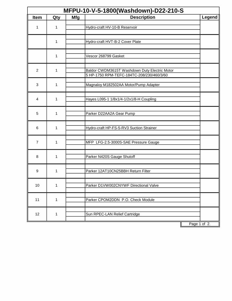
Item Qty Mfg Legend
MFPU-10-V-5-1800(Washdown)-D22-210-S
1 1
1
Description
Hydro-craft HV-10-B Reservoir
1 Vescor 268799 Gasket
Hydro-craft HVT-B-2 Cover Plate
2 1 Baldor CWDM3615T Washdown Duty Electric Motor
5 HP-1750 RPM-TEFC-184TC-208/230/460/3/60
3 1 Magnaloy M182502AA Motor/Pump Adapter
4 1 Hayes L095-1 1/8x1/4-1/2x1/8-H Coupling
5 1 Parker D22AA2A Gear Pump
6 1 Hydro-craft HP-FS-5-RV3 Suction Strainer
7 1 MFP LFG-2.5-3000S-SAE Pressure Gauge
8 1 Parker N420S Gauge Shutoff
9 1 Parker 12AT10CN25BBH Return Filter
10 1 Parker D1VW002CNYWF Directional Valve
11 1 Parker CPOM2DDN P.O. Check Module
Page 1 of 2.
12 1 Sun RPEC-LAN Relief Cartridge

Item Qty Mfg Legend
Page 2 of 2.
16 1 Sun W4P Sand. Body
15 1 Sun FDBA-LAN Pres. Comp. Flow Control Cartridge
14 1 Sun NCCB-LCN Flow Control Cartridge
Description
13 1 Daman AD03SPRVS8S Subplate
MFPU-10-V-5-1800(Washdown)-D22-210-S
