hydraulic motor series v12 variable...
TRANSCRIPT
Catalog 9129 8217-02June, 1998 GB
Hydraulic MotorSeries V12Variable Displacement
2
Hydraulic Motor Series V12
Content PageGeneral information 3
V12 cross section 3
Specifications 4
Efficiency diagrams 5
Ordering codes 6
Installation dimensions - ISO version 8
- Cartridge version 10
- SAE version 12
Bearing life 14
Controls 15
- AC 15
- AE 16
- AH 17
- EO 18
- EP 19
- HO 20
- HP 21
Control installation dimensions 22
Integrated flushing valve 23
Accessory valve blocks 24
Speed sensor 25
Split-flange kits 25
Motor installation 26
Conversion factors1 bar 14.5 psi
1 cm3 0.061 cu in
1 kg 2.20 lbf
1 kW 1.34 hp
1 l 0.264 US gallon
1mm 0.039 in
1 N 0.225 lbf
1 Nm 0.738 lbf ft9/5 °C + 32 1 °F
VOAC Hydraulics reserves the right to modify productswithout prior notice.Even though the brochure is revised and updatedcontinuously, there is always a possibility of errors.For more detailed information about the products,please contact VOAC Hydraulics.
3
Hydraulic Motor Series V12
1 2 3 4 5 6 7 8 9 10
General informationSeries V12 is a bent-axis, variable displacementmotor. It is intended for open and closed circuitsmainly in mobile applications but the V12 can alsobe utilized in a wide variety of other applications.
In the following, the basic design features of theV12 have been summarized.
• Max intermittent pressure to 480 bar andcontinuous operating pressure to 420 bar.
• Thanks to low weight pistons with laminated pis-ton rings and the compact design of the rotatingparts the V12 tolerates very high speeds.
• High allowable speeds and operating pressuresmeans high output power. Due to high overallefficiencies it remains high throughout the entiredisplacement range.
• The 9-piston design provides high start-uptorque and smooth operation.
• Wide displacement ratio (5:1).
• Broad range of controls and accessory valvesfor most applications.
• Small envelop size and a very high power-to-weight ratio.
• ISO, cartridge and SAE versions.
• Low noise levels due to a very compact andsturdy design with smooth fluid passages.
• Positive piston locking, strong synchronizingshaft, heavy-duty bearing set-up and smallnumber of parts add up to a compact and robustmotor with long service life and proven reliability.
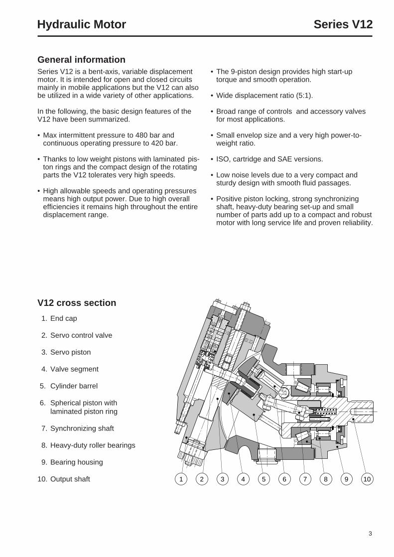
V12 cross section
11. End cap
12. Servo control valve
13. Servo piston
14. Valve segment
5. Cylinder barrel1
6. Spherical piston with15. laminated piston ring
17. Synchronizing shaft
18. Heavy-duty roller bearings
19. Bearing housing
10. Output shaft
4
Hydraulic Motor Series V12
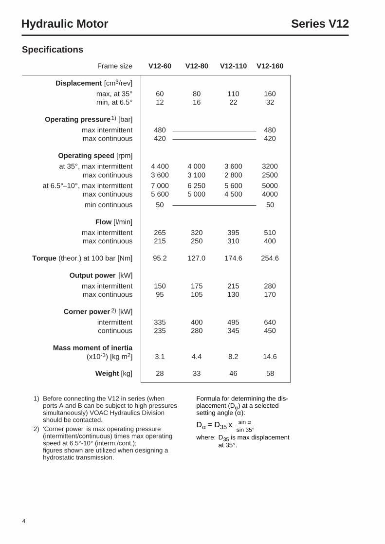
Formula for determining the dis-placement (Dα) at a selectedsetting angle (α):
Dα = D35 x
where: D35 is max displacementat 35°.
Specifications
sin α sin 35°
1) Before connecting the V12 in series (whenports A and B can be subject to high pressuressimultaneously) VOAC Hydraulics Divisionshould be contacted.
2) 'Corner power' is max operating pressure(intermittent/continuous) times max operatingspeed at 6.5°-10° (interm./cont.);figures shown are utilized when designing ahydrostatic transmission.
Frame size V12-60 V12-80 V12-110 V12-160
Displacement [cm3/rev]
max, at 35° 60 80 110 160min, at 6.5° 12 16 22 32
Operating pressure 1) [bar]
max intermittent 480 480max continuous 420 420
Operating speed [rpm]
at 35°, max intermittent 4 400 4 000 3 600 3200max continuous 3 600 3 100 2 800 2500
at 6.5°–10°, max intermittent 7 000 6 250 5 600 5000max continuous 5 600 5 000 4 500 4000
min continuous 50 50
Flow [l/min]
max intermittent 265 320 395 510max continuous 215 250 310 400
Torque (theor.) at 100 bar [Nm] 95.2 127.0 174.6 254.6
Output power [kW]
max intermittent 150 175 215 280max continuous 95 105 130 170
Corner power 2) [kW]
intermittent 335 400 495 640continuous 235 280 345 450
Mass moment of inertia(x10-3) [kg m2] 3.1 4.4 8.2 14.6
Weight [kg] 28 33 46 58
5
Hydraulic Motor Series V12
[%]
100
90
800 1000 2000 3000 4000 5000 [rpm]
Volumetric [%]
100
90
800 1000 2000 3000 4000 5000 [rpm]
Overall
Overall
Overall
Overall
V12-60
[%]
100
90
800 1000 2000 3000 4000 5000 [rpm]
Volumetric [%]
100
90
800 1000 2000 3000 4000 5000 [rpm]
V12-80
[%]
100
90
800 1000 2000 3000 4000 5000 [rpm]
Volumetric [%]
100
90
800 1000 2000 3000 4000 5000 [rpm]
V12-110
[%]
100
90
800 1000 2000 3000 4000 5000 [rpm]
Volumetric [%]
100
90
800 1000 2000 3000 4000 5000 [rpm]
V12-160
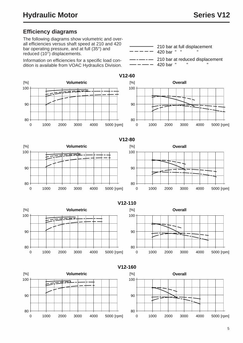
210 bar at full displacement420 bar " " "
210 bar at reduced displacement420 bar " " "
Efficiency diagramsThe following diagrams show volumetric and over-all efficiencies versus shaft speed at 210 and 420bar operating pressure, and at full (35°) andreduced (10°) displacements.
Information on efficiencies for a specific load con-dition is available from VOAC Hydraulics Division.
6
Hydraulic Motor Series V12
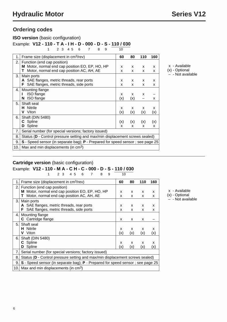
1. Frame size (displacement in cm3/rev) 60 80 110 1602. Function (end cap position)
M Motor, normal end cap position EO, EP, HO, HP x x x xT Motor, normal end cap position AC, AH, AE x x x x
3. Main portsA SAE flanges, metric threads, rear ports x x x xF SAE flanges, metric threads, side ports x x x x
4. Mounting flangeI ISO flange x x x –N ISO flange (x) (x) – x
5. Shaft sealH Nitrile x x x xV Viton (x) (x) (x) (x)
6. Shaft (DIN 5480)C Spline (x) (x) (x) (x)D Spline x x x x
7. Serial number (for special versions; factory issued)8. Status (D - Control pressure setting and max/min displacement screws sealed)9. S - Speed sensor (in separate bag); P - Prepared for speed sensor ; see page 25
10. Max and min displacements (in cm3)
1. Frame size (displacement in cm3/rev) 60 80 110 1602. Function (end cap position)
M Motor, normal end cap position EO, EP, HO, HP x x x xT Motor, normal end cap position AC, AH, AE x x x x
3. Main portsA SAE flanges, metric threads, rear ports x x x xF SAE flanges, metric threads, side ports x x x x
4. Mounting flangeC Cartridge flange x x x –
5. Shaft sealH Nitrile x x x xV Viton (x) (x) (x) (x)
6. Shaft (DIN 5480)C Spline x x x xD Spline (x) (x) (x) (x)
7. Serial number (for special versions; factory issued)8. Status (D - Control pressure setting and max/min displacement screws sealed)9. S - Speed sensor (in separate bag); P - Prepared for speed sensor ; see page 25
10. Max and min displacements (in cm3)
ISO version (basic configuration)Example: V12 - 110 - T A - I H - D - 000 - D - S - 110 / 030
1 2 3 4 5 6 7 8 9 10
Ordering codes
Cartridge version (basic configuration)Example: V12 - 110 - M A - C H - C - 000 - D - S - 110 / 030
1 2 3 4 5 6 7 8 9 10
x - Available(x) - Optional– - Not available
x - Available(x) - Optional– - Not available
7
Hydraulic Motor Series V12
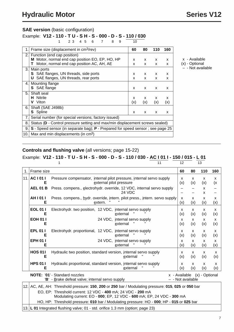
1. Frame size (displacement in cm3/rev) 60 80 110 1602. Function (end cap position)
M Motor, normal end cap position EO, EP, HO, HP x x x xT Motor, normal end cap position AC, AH, AE x x x x
3. Main portsS SAE flanges, UN threads, side ports x x x xU SAE flanges, UN threads, rear ports x x x x
4. Mounting flangeS SAE flange x x x x
5. Shaft sealH Nitrile x x x xV Viton (x) (x) (x) (x)
6. Shaft (SAE J498b)S Spline x x x x
7. Serial number (for special versions; factory issued)8. Status (D - Control pressure setting and max/min displacement screws sealed)9. S - Speed sensor (in separate bag); P - Prepared for speed sensor ; see page 25
10. Max and min displacements (in cm3)
Controls and flushing valve (all versions; page 15-22)
Example: V12 - 110 - T U - S H - S - 000 - D - S - 110 / 030 - AC I 01 I - 150 / 015 - L 011 11 12 13
SAE version (basic configuration)Example: V12 - 110 - T U - S H - S - 000 - D - S - 110 / 030
1 2 3 4 5 6 7 8 9 10
1. Frame size 60 80 110 160
11. AC I 01 I Pressure compensator, internal pilot pressure, internal servo supply x x x xE external pilot pressure (x) (x) (x) (x
AEL 01 B Press. compens., electrohydr. override, 12 VDC, internal servo supply – – x – 24 VDC – – x –
AH I 01 I Press. compens., hydr. override, intern. pilot press., intern. servo supply x x x xE extern. " " (x) (x) (x) (x)
EOL 01 I Electrohydr. two position, 12 VDC, internal servo supply x x x xE external " " (x) (x) (x) (x)
EOH 01 I 24 VDC, internal servo supply x x x xE external " " (x) (x) (x) (x)
EPL 01 I Electrohydr. proportional, 12 VDC, internal servo supply x x x xE external " " (x) (x) (x) (x)
EPH 01 I 24 VDC, internal servo supply x x x xE external " " (x) (x) (x) (x)
HOS 01I Hydraulic two position, standard version, internal servo supply x x x xE external " " (x) (x) (x) (x)
HPS 01 I Hydraulic proportional, standard version, internal servo supply x x x xE external " " (x) (x) (x) (x)
NOTE: '01' - Standard nozzles x - Available (x) - Optional'B ' - Brake defeat valve; internal servo supply – - Not available
12. AC, AE, AH: Threshold pressure: 150, 200 or 250 bar / Modulating pressure: 015, 025 or 050 barEO, EP: Threshold current: 12 VDC - 400 mA; 24 VDC - 200 mA
Modulating current: EO - 000; EP, 12 VDC - 600 mA; EP, 24 VDC - 300 mAHO, HP: Threshold pressure: 010 bar / Modulating pressure: HO - 000; HP - 015 or 025 bar
13. L 01 Integrated flushing valve; 01 - std. orifice 1.3 mm (option; page 23)
x - Available(x) - Optional– - Not available
8
Hydraulic Motor Series V12
V12-80
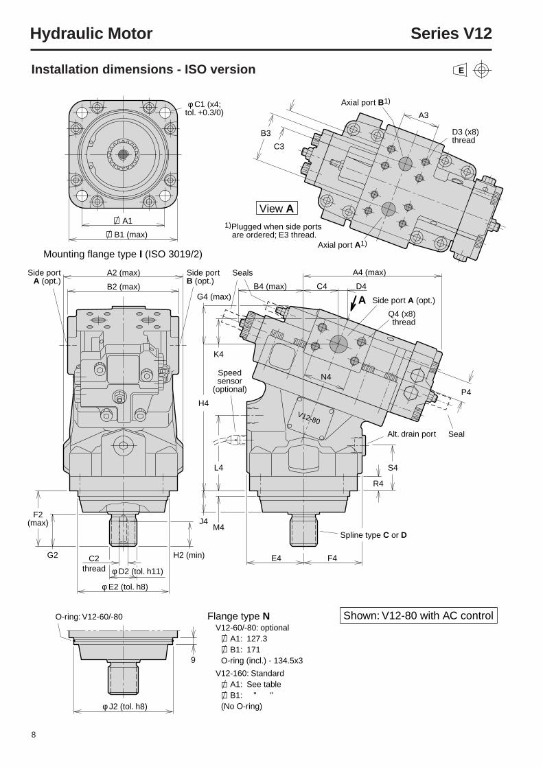
φ C1 (x4; tol. +0.3/0)
B1 (max)
A1
C3
A3
D3 (x8)thread
B3
A2 (max)Side portA (opt.)
Side portB (opt.)
A4 (max)
B4 (max) C4
K4
N4
H4
J4
L4
M4
Speed sensor
(optional)
E4 F4
Spline type C or D
Alt. drain port
G4 (max)
P4
S4
R4
D4
Side port A (opt.)
Q4 (x8)thread
B2 (max)
Mounting flange type I (ISO 3019/2)
F2(max)
C2thread
G2 H2 (min)
9
φ D2 (tol. h11)
φ E2 (tol. h8)
φ J2 (tol. h8)
Shown: V12-80 with AC controlFlange type NV12-60/-80: optional
A1: 127.3B1: 171
O-ring (incl.) - 134.5x3
V12-160: StandardA1: See tableB1: " "
(No O-ring)
Axial port A1)
1)Plugged when side ports are ordered; E3 thread.
Axial port B1)
View A
A
O-ring: V12-60/-80
Seal
Seals
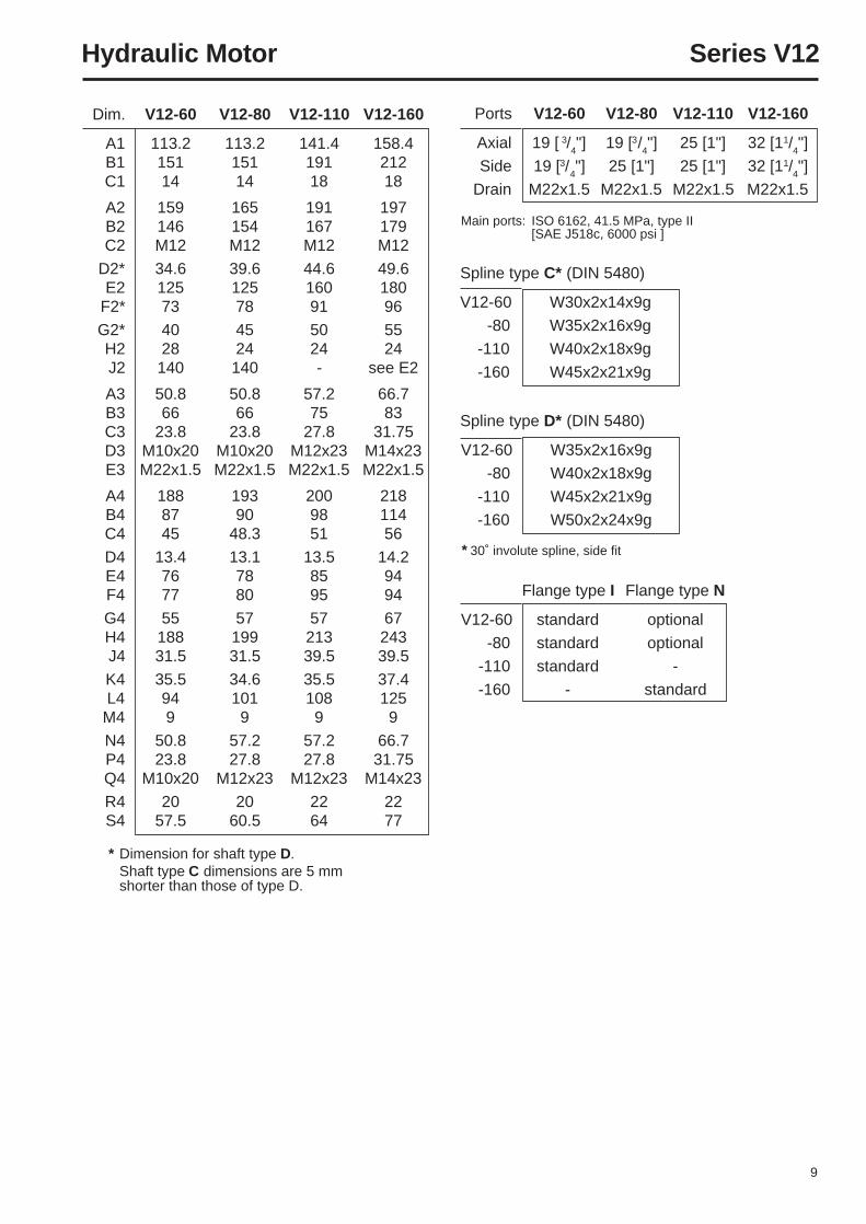
Installation dimensions - ISO version E
9
Hydraulic Motor Series V12
Ports V12-60 V12-80 V12-110 V12-160
Axial 19 [ 3/4"] 19 [3/
4"] 25 [1"] 32 [11/
4"]
Side 19 [3/4"] 25 [1"] 25 [1"] 32 [11/
4"]
Drain M22x1.5 M22x1.5 M22x1.5 M22x1.5
Main ports: ISO 6162, 41.5 MPa, type II[SAE J518c, 6000 psi ]
Spline type C* (DIN 5480)
V12-60 W30x2x14x9g
-80 W35x2x16x9g
-110 W40x2x18x9g
-160 W45x2x21x9g
Spline type D* (DIN 5480)
V12-60 W35x2x16x9g
-80 W40x2x18x9g
-110 W45x2x21x9g
-160 W50x2x24x9g
* 30˚ involute spline, side fit
* Dimension for shaft type D.Shaft type C dimensions are 5 mmshorter than those of type D.
Flange type I Flange type N
V12-60 standard optional
-80 standard optional
-110 standard -
-160 - standard
Dim. V12-60 V12-80 V12-110 V12-160
A1 113.2 113.2 141.4 158.4B1 151 151 191 212C1 14 14 18 18
A2 159 165 191 197B2 146 154 167 179C2 M12 M12 M12 M12
D2* 34.6 39.6 44.6 49.6E2 125 125 160 180
F2* 73 78 91 96
G2* 40 45 50 55H2 28 24 24 24J2 140 140 - see E2
A3 50.8 50.8 57.2 66.7B3 66 66 75 83C3 23.8 23.8 27.8 31.75D3 M10x20 M10x20 M12x23 M14x23E3 M22x1.5 M22x1.5 M22x1.5 M22x1.5
A4 188 193 200 218B4 87 90 98 114C4 45 48.3 51 56
D4 13.4 13.1 13.5 14.2E4 76 78 85 94F4 77 80 95 94
G4 55 57 57 67H4 188 199 213 243J4 31.5 31.5 39.5 39.5
K4 35.5 34.6 35.5 37.4L4 94 101 108 125M4 9 9 9 9
N4 50.8 57.2 57.2 66.7P4 23.8 27.8 27.8 31.75Q4 M10x20 M12x23 M12x23 M14x23
R4 20 20 22 22S4 57.5 60.5 64 77
10
Hydraulic Motor Series V12
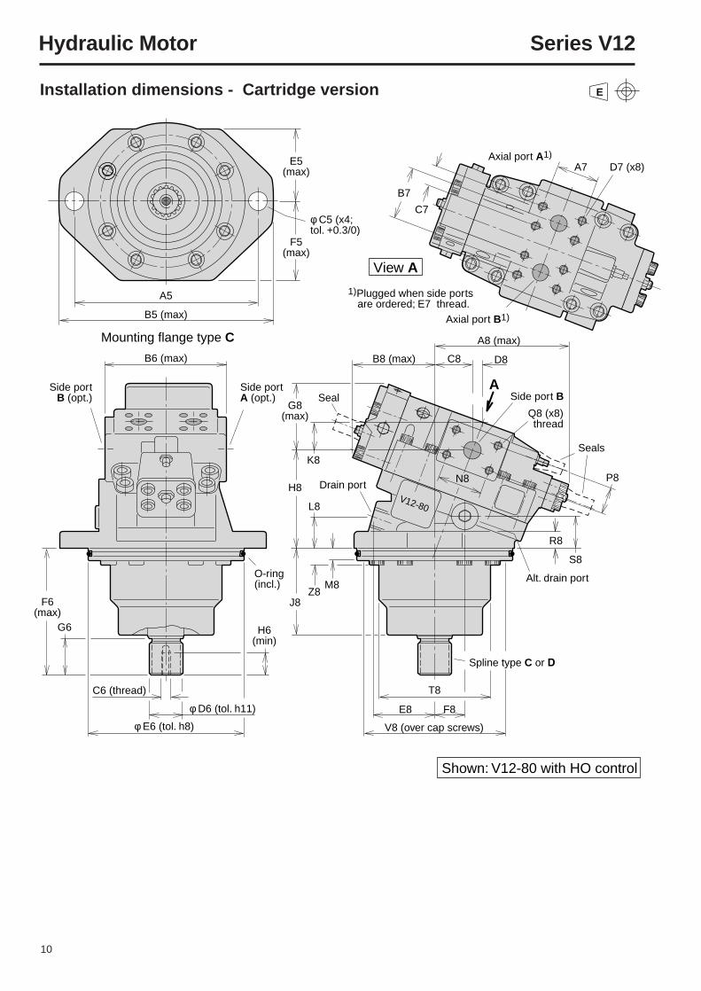
Installation dimensions - Cartridge version E
φ C5 (x4; tol. +0.3/0)
E5(max)
F5(max)
A5
B7
C7
A7 D7 (x8)
B5 (max)
B6 (max)
F6 (max)
C6 (thread)
G6
φ D6 (tol. h11)
φ E6 (tol. h8)
Side port B (opt.)
Side port A (opt.)
Mounting flange type C
Shown: V12-80 with HO control
View A
A
A8 (max)
C8
K8
L8
Z8M8
T8
R8
S8
P8
Spline type C or D
Alt. drain port
E8
V8 (over cap screws)
F8
G8(max)
H8
J8
H6(min)
D8
N8
B8 (max)
Drain port
O-ring(incl.)
Seals
V12-80
Axial port B1)
Side port B
1)Plugged when side ports are ordered; E7 thread.
Axial port A1)
Q8 (x8)thread
Seal
11
Hydraulic Motor Series V12
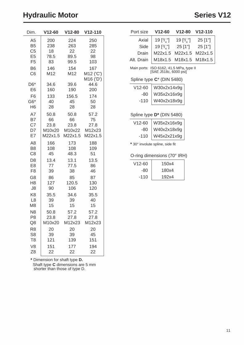
Port size V12-60 V12-80 V12-110
Axial 19 [3/4"] 19 [3/4"] 25 [1"]
Side 19 [3/4"] 25 [1"] 25 [1"]
Drain M22x1.5 M22x1.5 M22x1.5
Alt. Drain M18x1.5 M18x1.5 M18x1.5
* 30° involute spline, side fit
* Dimension for shaft type D. Shaft type C dimensions are 5 mm
shorter than those of type D.
Main ports: ISO 6162, 41.5 MPa, type II[SAE J518c, 6000 psi]
Spline type C* (DIN 5480)
V12-60 W30x2x14x9g
-80 W35x2x16x9g
-110 W40x2x18x9g
Spline type D* (DIN 5480)
V12-60 W35x2x16x9g
-80 W40x2x18x9g
-110 W45x2x21x9g
O-ring dimensions (70° IRH)
V12-60 150x4
-80 180x4
-110 192x4
Dim. V12-60 V12-80 V12-110
A5 200 224 250B5 238 263 285C5 18 22 22E5 78.5 89.5 98F5 83 99.5 103
B6 146 154 167C6 M12 M12 M12 ('C')
M16 ('D')D6* 34.6 39.6 44.6E6 160 190 200
F6 133 156.5 174G6* 40 45 50H6 28 28 28
A7 50.8 50.8 57.2B7 66 66 75C7 23.8 23.8 27.8D7 M10x20 M10x22 M12x23E7 M22x1.5 M22x1.5 M22x1.5
A8 166 173 188B8 108 108 109C8 45 48.3 51
D8 13.4 13.1 13.5E8 77 77.5 86F8 39 38 46
G8 86 85 87H8 127 120.5 130J8 90 106 120
K8 35.5 34.6 35.5L8 39 39 40M8 15 15 15
N8 50.8 57.2 57.2P8 23.8 27.8 27.8Q8 M10x20 M12x23 M12x23
R8 20 20 20S8 39 39 45T8 121 139 151
V8 151 177 194Z8 22 22 22
12
Hydraulic Motor Series V12
V12-80
Shown: V12-80 with AC control
A9
φ C9 (x4;tol. +0.3/0)
B9 (max)
A12 (max)
B12 (max)
A10 (max)
φ E10 (tol. h8)
φ D10 (tol. 0/-0.13)
B10 (max)Side portA (opt.)
Side portB (opt.)
View A
A
Mounting flange type S (SAE J744)
8
H10 (min)
G10
C10 (thread;V12-110/-160)
C11
B11
A11 D11 (x8)thread
C12
H12
J12
L12S12
P12
Alt. drain port
R12
E12 F12
Spline shaft type S
O-ring 117.1x3.53(V12-60/-80)
K12
G12(max)
D12
N11
Axial port B1)
Axial port A1)
1) Plugged when side ports are ordered; E11 thread
Side port A(optional)Q12 (x8)
thread
Speed sensor
(optional)
Seals
Seal
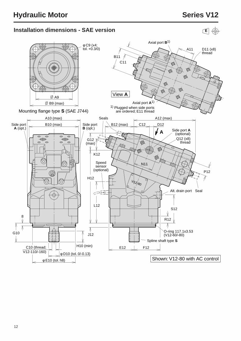
Installation dimensions - SAE version E
13
Hydraulic Motor Series V12
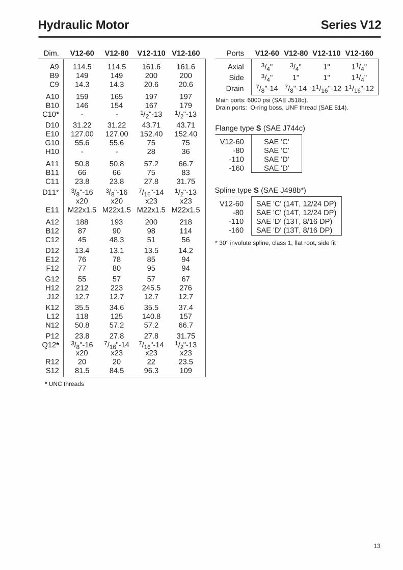
Flange type S (SAE J744c)
V12-60 SAE 'C'-80 SAE 'C'
-110 SAE 'D'-160 SAE 'D'
Spline type S (SAE J498b*)
V12-60 SAE 'C' (14T, 12/24 DP)-80 SAE 'C' (14T, 12/24 DP)
-110 SAE 'D' (13T, 8/16 DP)-160 SAE 'D' (13T, 8/16 DP)
Dim. V12-60 V12-80 V12-110 V12-160
A9 114.5 114.5 161.6 161.6B9 149 149 200 200C9 14.3 14.3 20.6 20.6
A10 159 165 197 197B10 146 154 167 179
C10* - - 1/2"-13 1/2"-13
D10 31.22 31.22 43.71 43.71E10 127.00 127.00 152.40 152.40G10 55.6 55.6 75 75H10 - - 28 36
A11 50.8 50.8 57.2 66.7B11 66 66 75 83C11 23.8 23.8 27.8 31.75
D11* 3/8"-16 3/8"-16 7/16"-14 1/2"-13x20 x20 x23 x23
E11 M22x1.5 M22x1.5 M22x1.5 M22x1.5
A12 188 193 200 218B12 87 90 98 114C12 45 48.3 51 56
D12 13.4 13.1 13.5 14.2E12 76 78 85 94F12 77 80 95 94
G12 55 57 57 67H12 212 223 245.5 276J12 12.7 12.7 12.7 12.7
K12 35.5 34.6 35.5 37.4L12 118 125 140.8 157N12 50.8 57.2 57.2 66.7
P12 23.8 27.8 27.8 31.75Q12* 3/8"-16 7/16"-14 7/16"-14 1/2"-13
x20 x23 x23 x23R12 20 20 22 23.5S12 81.5 84.5 96.3 109
Ports V12-60 V12-80 V12-110 V12-160
Axial 3/4" 3/4" 1" 11/4"
Side 3/4" 1" 1" 11/4"
Drain 7/8"-14 7/8"-14 11/16"-12 11/16"-12
Main ports: 6000 psi (SAE J518c).Drain ports: O-ring boss, UNF thread (SAE 514).
* UNC threads
* 30° involute spline, class 1, flat root, side fit
14
Hydraulic Motor Series V12
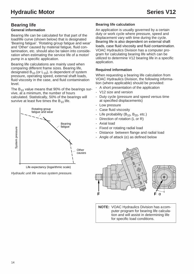
Rotating groupfatigue and wear
Bearingfatigue
Other causes
Life expectancy (logarithmic scale)
Sys
tem
pre
ssur
e
F α F
Hydraulic unit life versus system pressure.
Bearing lifeGeneral information
Bearing life can be calculated for that part of theload/life curve (shown below) that is designated'Bearing fatigue'. 'Rotating group fatigue and wear'and 'Other' caused by material fatigue, fluid con-tamination, etc. should also be taken into conside-ration when estimating the service life of a motor/pump in a specific application.
Bearing life calculations are mainly used whencomparing different frame sizes. Bearing life,designated B10 (or L10), is dependent of systempressure, operating speed, external shaft loads,fluid viscosity in the case, and fluid contaminationlevel.
The B10 value means that 90% of the bearings sur-vive, at a minimum, the number of hourscalculated. Statistically, 50% of the bearings willsurvive at least five times the B10 life.
Bearing life calculation
An application is usually governed by a certainduty or work cycle where pressure, speed anddisplacement vary with time during the cycle.Bearing life is also dependent on external shaftloads, case fluid viscosity and fluid contamination.VOAC Hydraulics Division has a computer pro-gram for calculating bearing life which can beutilized to determine V12 bearing life in a specificapplication.
Required information
When requesting a bearing life calculation fromVOAC Hydraulics Division, the following informa-tion (where applicable) should be provided:- A short presentation of the application- V12 size and version- Duty cycle (pressure and speed versus time
at specified displacements)- Low pressure- Case fluid viscosity- Life probability (B10, B20, etc.)- Direction of rotation (L or R)- Axial load- Fixed or rotating radial load- Distance between flange and radial load- Angle of attack (α) as defined below
NOTE: VOAC Hydraulics Division has acom-puter program for bearing life calcula-tion and will assist in determining lifefor specific load conditions.
15
Hydraulic Motor Series V12
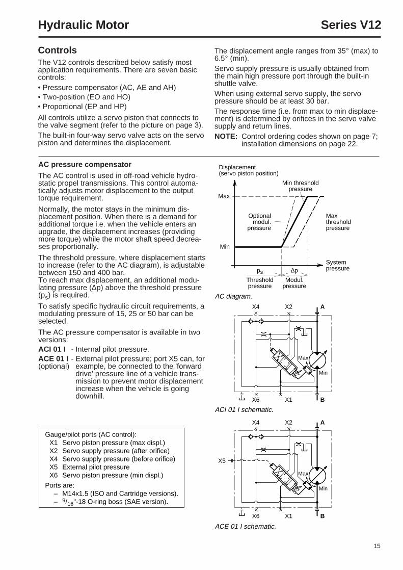
Displacement(servo piston position)
Maxthreshold pressure
System pressure
Max
Min
Optionalmodul.
pressure
Min thresholdpressure
∆p
Modul.pressure
ps
Thresholdpressure
AC diagram.
ACI 01 I schematic.
ACE 01 I schematic.
X4 X2 A
X4 X2 A
X6 X1 B
X6
X5
X1 B
Max
Min
Max
Min
ControlsThe V12 controls described below satisfy mostapplication requirements. There are seven basiccontrols:• Pressure compensator (AC, AE and AH)• Two-position (EO and HO)• Proportional (EP and HP)
All controls utilize a servo piston that connects tothe valve segment (refer to the picture on page 3).The built-in four-way servo valve acts on the servopiston and determines the displacement.
AC pressure compensator
The AC control is used in off-road vehicle hydro-static propel transmissions. This control automa-tically adjusts motor displacement to the outputtorque requirement.
Normally, the motor stays in the minimum dis-placement position. When there is a demand foradditional torque i.e. when the vehicle enters anupgrade, the displacement increases (providingmore torque) while the motor shaft speed decrea-ses proportionally.
The threshold pressure, where displacement startsto increase (refer to the AC diagram), is adjustablebetween 150 and 400 bar.To reach max displacement, an additional modu-lating pressure (∆p) above the threshold pressure(ps) is required.
To satisfy specific hydraulic circuit requirements, amodulating pressure of 15, 25 or 50 bar can beselected.
The AC pressure compensator is available in twoversions:ACI 01 I - Internal pilot pressure.ACE 01 I - External pilot pressure; port X5 can, for(optional) example, be connected to the 'forward
drive' pressure line of a vehicle trans-mission to prevent motor displacementincrease when the vehicle is goingdownhill.
The displacement angle ranges from 35° (max) to6.5° (min).Servo supply pressure is usually obtained fromthe main high pressure port through the built-inshuttle valve.When using external servo supply, the servopressure should be at least 30 bar.The response time (i.e. from max to min displace-ment) is determined by orifices in the servo valvesupply and return lines.NOTE: Control ordering codes shown on page 7;
installation dimensions on page 22.
Gauge/pilot ports (AC control):X1 Servo piston pressure (max displ.)X2 Servo supply pressure (after orifice)X4 Servo supply pressure (before orifice)X5 External pilot pressureX6 Servo piston pressure (min displ.)
Ports are:– M14x1.5 (ISO and Cartridge versions).– 9/16"-18 O-ring boss (SAE version).
16
Hydraulic Motor Series V12
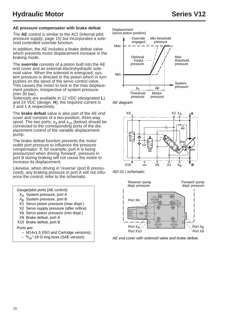
Displacement(servo piston position)
Maxthreshold pressure
System pressure
Max
Min
Optionalmodul.
pressure
Min thresholdpressure
Overrideengaged
∆p
Modul.pressure
ps
Thresholdpressure
AE diagram.
AEI 01 I schematic.
X9 X2 XA
XB
A
X10 X6 X1 B
Max
Min
AE end cover with solenoid valve and brake defeat.
'Forward' pumpdispl. pressure
'Reverse' pumpdispl. pressure
Port X6
Port XAPort X10
Port XBPort X9
Gauge/pilot ports (AE control):XA System pressure, port AXB System pressure, port BX1 Servo piston pressure (max displ.)X2 Servo supply pressure (after orifice)X6 Servo piston pressure (min displ.)X9 Brake defeat, port A
X10 Brake defeat, port B
Ports are:– M14x1.5 (ISO and Cartridge versions).– 9/16"-18 O-ring boss (SAE version).
AE pressure compensator with brake defeat
The AE control is similar to the ACI (internal pilotpressure supply; page 15) but incorporates a sole-noid controlled override function.
In addition, the AE includes a brake defeat valvewhich prevents motor displacement increase in thebraking mode.
The override consists of a piston built into the AEend cover and an external electrohydraulic sole-noid valve. When the solenoid is energized, sys-tem pressure is directed to the piston which in turnpushes on the spool of the servo control valve.This causes the motor to lock in the max displace-ment position, irrespective of system pressure(min 30 bar).Solenoids are available in 12 VDC (designated L)and 24 VDC (design. H); the required current is2 and 1 A respectively.
The brake defeat valve is also part of the AE endcover and consists of a two-position, three-wayspool. The two ports, x9 and x10 (below) should beconnected to the corresponding ports of the dis-placement control of the variable displacementpump.
The brake defeat function prevents the motoroutlet port pressure to influence the pressurecompensator. If, for example, port A is beingpressurized when driving 'forward', pressure inport B during braking will not cause the motor toincrease its displacement.
Likewise, when driving in 'reverse' (port B pressu-rized), any braking pressure in port A will not influ-ence the control; refer to the schematic.
17
Hydraulic Motor Series V12
Displacement(servo piston position)
Maxthreshold pressure
System pressure
Max
Min
Optionalmodul.
pressure
Min thresholdpressure
Overrideengaged
∆p
Modul.pressure
ps
Thresholdpressure
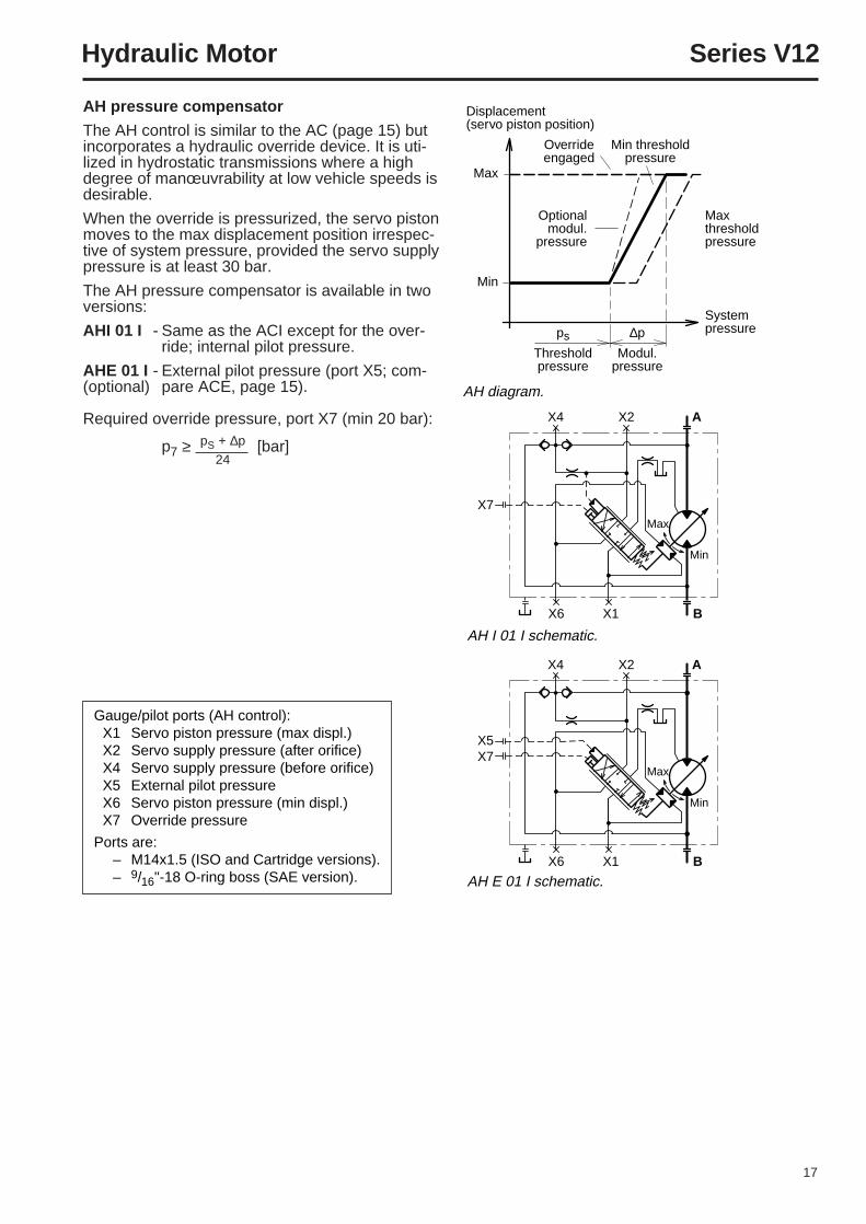
AH diagram.
AH I 01 I schematic.
X4
X7
X2 A
X6 X1 B
Max
Min
AH E 01 I schematic.
X4
X7X5
X2 A
X6 X1 B
Max
Min
pS + ∆p24
Gauge/pilot ports (AH control):X1 Servo piston pressure (max displ.)X2 Servo supply pressure (after orifice)X4 Servo supply pressure (before orifice)X5 External pilot pressureX6 Servo piston pressure (min displ.)X7 Override pressure
Ports are:– M14x1.5 (ISO and Cartridge versions).– 9/16"-18 O-ring boss (SAE version).
AH pressure compensator
The AH control is similar to the AC (page 15) butincorporates a hydraulic override device. It is uti-lized in hydrostatic transmissions where a highdegree of manœuvrability at low vehicle speeds isdesirable.
When the override is pressurized, the servo pistonmoves to the max displacement position irrespec-tive of system pressure, provided the servo supplypressure is at least 30 bar.
The AH pressure compensator is available in twoversions:
AHI 01 I - Same as the ACI except for the over-ride; internal pilot pressure.
AHE 01 I - External pilot pressure (port X5; com-(optional) pare ACE, page 15).
Required override pressure, port X7 (min 20 bar):
p7 ≥ [bar]
18
Hydraulic Motor Series V12
Displacement(servo piston position)
Solenoidcurrent
Max
Min
IsThreshold
current
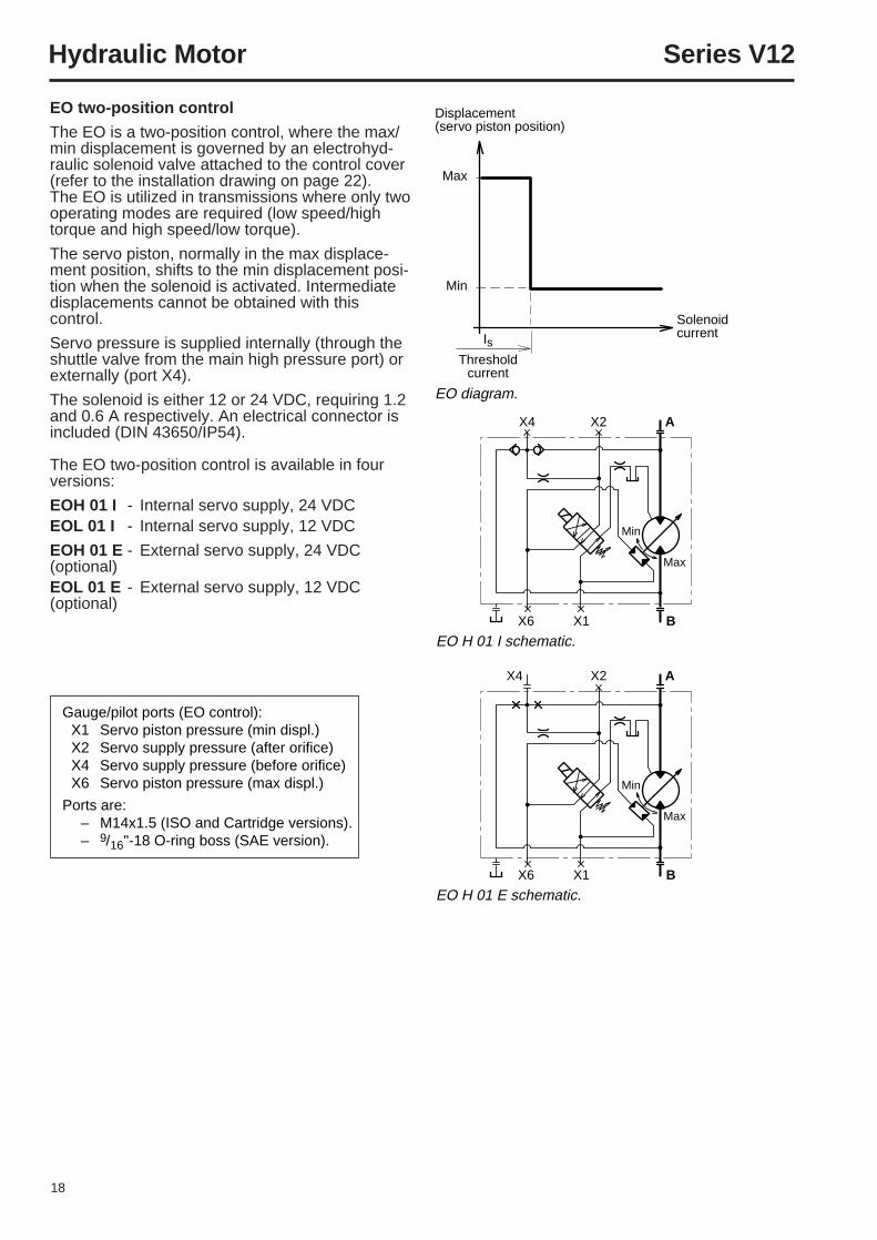
EO diagram.
EO H 01 E schematic.
X4 X2 A
X6 X1 B
Max
Min
EO H 01 I schematic.
X4 X2 A
X6 X1 B
Max
Min
EO two-position control
The EO is a two-position control, where the max/min displacement is governed by an electrohyd-raulic solenoid valve attached to the control cover(refer to the installation drawing on page 22).The EO is utilized in transmissions where only twooperating modes are required (low speed/hightorque and high speed/low torque).
The servo piston, normally in the max displace-ment position, shifts to the min displacement posi-tion when the solenoid is activated. Intermediatedisplacements cannot be obtained with thiscontrol.
Servo pressure is supplied internally (through theshuttle valve from the main high pressure port) orexternally (port X4).
The solenoid is either 12 or 24 VDC, requiring 1.2and 0.6 A respectively. An electrical connector isincluded (DIN 43650/IP54).
The EO two-position control is available in fourversions:
EOH 01 I - Internal servo supply, 24 VDCEOL 01 I - Internal servo supply, 12 VDC
EOH 01 E - External servo supply, 24 VDC(optional)EOL 01 E - External servo supply, 12 VDC(optional)
Gauge/pilot ports (EO control):X1 Servo piston pressure (min displ.)X2 Servo supply pressure (after orifice)X4 Servo supply pressure (before orifice)X6 Servo piston pressure (max displ.)
Ports are:– M14x1.5 (ISO and Cartridge versions).– 9/16"-18 O-ring boss (SAE version).
19
Hydraulic Motor Series V12
Shaft speed
Solenoidcurrent∆I
Modulatingcurrent
IsThreshold
current
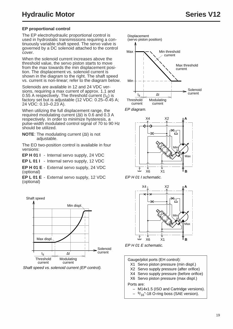
Shaft speed vs. solenoid current (EP control).
Min displ.
Max displ.
Displacement(servo piston position)
Max threshold current
Solenoidcurrent
Max
Min
Min thresholdcurrent
∆I
Modulatingcurrent
IsThreshold
current
EP diagram.
EP H 01 I schematic.
X4 X2 A
X6 X1 B
Max
Min
EP H 01 E schematic.
X4 X2 A
X6 X1 B
Max
Min
Gauge/pilot ports (EH control):X1 Servo piston pressure (min displ.)X2 Servo supply pressure (after orifice)X4 Servo supply pressure (before orifice)X6 Servo piston pressure (max displ.)
Ports are:– M14x1.5 (ISO and Cartridge versions).– 9/16"-18 O-ring boss (SAE version).
EP proportional control
The EP electrohydraulic proportional control isused in hydrostatic transmissions requiring a con-tinuously variable shaft speed. The servo valve isgoverned by a DC solenoid attached to the controlcover.
When the solenoid current increases above thethreshold value, the servo piston starts to movefrom the max towards the min displacement posi-tion. The displacement vs. solenoid current isshown in the diagram to the right. The shaft speedvs. current is non-linear; refer to the diagram below.
Solenoids are available in 12 and 24 VDC ver-sions, requiring a max current of approx. 1.1 and0.55 A respectively. The threshold current (IS) isfactory set but is adjustable (12 VDC: 0.25–0.45 A;24 VDC: 0.10–0.23 A).
When utilizing the full displacement range, therequired modulating current (∆I) is 0.6 and 0.3 Arespectively. In order to minimize hysteresis, apulse-width modulated control signal of 70 to 90 Hzshould be utilized.
NOTE: The modulating current (∆I) is notadjustable.
The EO two-position control is available in fourversions:EP H 01 I - Internal servo supply, 24 VDCEP L 01 I - Internal servo supply, 12 VDC
EP H 01 E - External servo supply, 24 VDC(optional)EP L 01 E - External servo supply, 12 VDC(optional)
20
Hydraulic Motor Series V12
Displacement(servo piston position)
Min thresholdpressure
Max thresholdpressure
Pilot pressure
Max
Min
ps
Thresholdpress. (min)
Adjustmentrange
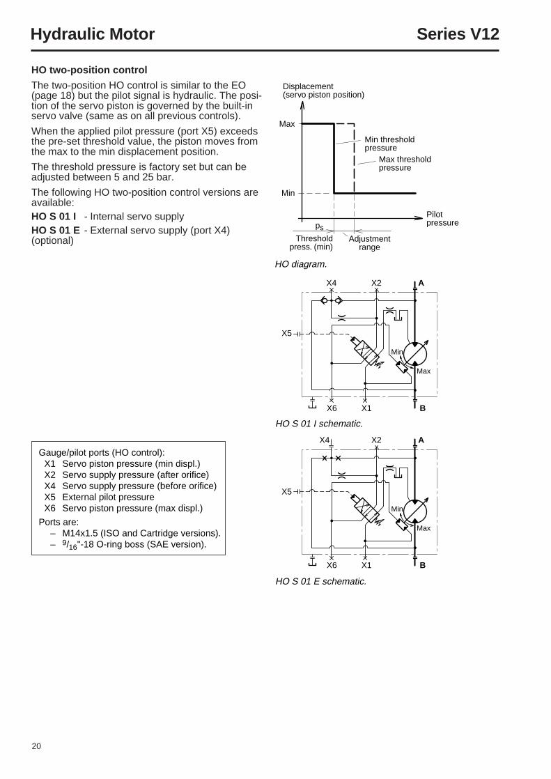
HO diagram.
HO S 01 I schematic.
X4
X5
X2 A
X6 X1 B
Max
Min
HO S 01 E schematic.
X4
X5
X2 A
X6 X1 B
Max
Min
Gauge/pilot ports (HO control):X1 Servo piston pressure (min displ.)X2 Servo supply pressure (after orifice)X4 Servo supply pressure (before orifice)X5 External pilot pressureX6 Servo piston pressure (max displ.)
Ports are:– M14x1.5 (ISO and Cartridge versions).– 9/16"-18 O-ring boss (SAE version).
HO two-position control
The two-position HO control is similar to the EO(page 18) but the pilot signal is hydraulic. The posi-tion of the servo piston is governed by the built-inservo valve (same as on all previous controls).
When the applied pilot pressure (port X5) exceedsthe pre-set threshold value, the piston moves fromthe max to the min displacement position.
The threshold pressure is factory set but can beadjusted between 5 and 25 bar.
The following HO two-position control versions areavailable:HO S 01 I - Internal servo supplyHO S 01 E - External servo supply (port X4)(optional)
21
Hydraulic Motor Series V12
Shaft speed
Pilotpressure∆p
Modulatingpressure
ps
Thresholdpressure
Shaft speed vs. pilot pressure (HP control).
Min displ.
Max displ.
Displacement(servo piston position)
Min thresholdpressure
Max thresholdpressure
Pilot pressure
Max
Min
ps
Thresholdpressure
∆p
Modulatingpressure
HP diagram.
HP S 01 I schematic.
X4
X5
X2 A
X6 X1 B
Max
Min
HP S 01 E schematic.
X4
X5
X2 A
X6 X1 B
Max
Min
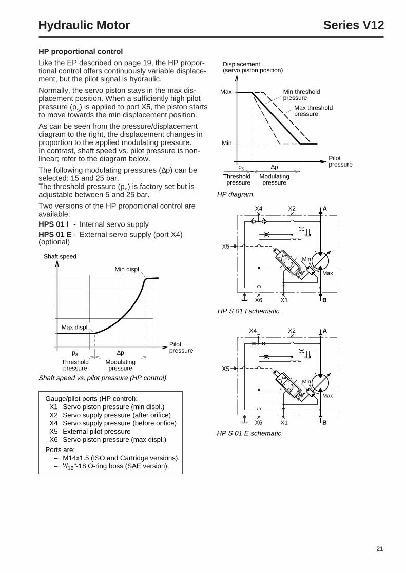
Gauge/pilot ports (HP control):X1 Servo piston pressure (min displ.)X2 Servo supply pressure (after orifice)X4 Servo supply pressure (before orifice)X5 External pilot pressureX6 Servo piston pressure (max displ.)
Ports are:– M14x1.5 (ISO and Cartridge versions).– 9/16"-18 O-ring boss (SAE version).
HP proportional control
Like the EP described on page 19, the HP propor-tional control offers continuously variable displace-ment, but the pilot signal is hydraulic.
Normally, the servo piston stays in the max dis-placement position. When a sufficiently high pilotpressure (pS) is applied to port X5, the piston startsto move towards the min displacement position.
As can be seen from the pressure/displacementdiagram to the right, the displacement changes inproportion to the applied modulating pressure.In contrast, shaft speed vs. pilot pressure is non-linear; refer to the diagram below.
The following modulating pressures (∆p) can beselected: 15 and 25 bar.The threshold pressure (pS) is factory set but isadjustable between 5 and 25 bar.
Two versions of the HP proportional control areavailable:HPS 01 I - Internal servo supplyHPS 01 E - External servo supply (port X4)(optional)
22
Hydraulic Motor Series V12
A1 A2
E1 E2
H1 H2
A3
A4
E3
H3
Port X7
Port X4
Port X2Port X1
Port X6Port X5
Override(AH control)
NOTE:End cap position T
Port X4
Port X2Port X1
NOTE:End cap position M
NOTE:End cap position M
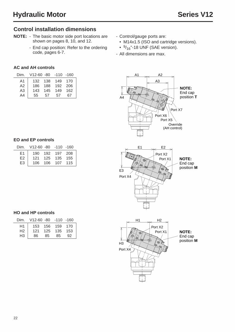
Control installation dimensionsNOTE: - The basic motor side port locations are
shown on pages 8, 10, and 12.
- End cap position: Refer to the orderingcode, pages 6-7.
HO and HP controls
Dim. V12-60 -80 -110 -160
H1 153 156 159 170H2 121 125 135 153H3 86 85 85 92
EO and EP controls
Dim. V12-60 -80 -110 -160
E1 190 192 197 208E2 121 125 135 155E3 106 106 107 115
AC and AH controls
Dim. V12-60 -80 -110 -160
A1 132 138 149 170A2 186 188 192 206A3 143 145 149 162A4 55 57 57 67
- Control/gauge ports are:• M14x1.5 (ISO and cartridge versions).• 9/16"-18 UNF (SAE version).
- All dimensions are max.
23
Hydraulic Motor Series V12
Nozzle (behindcover plate)
Flushingvalve
Flushing Nozzle valve
A
B
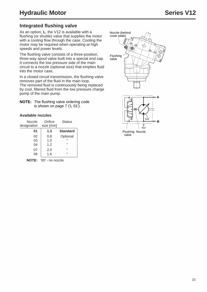
Available nozzles
Nozzle Orifice Statusdesignation size [mm]
01 1.3 Standard
02 0.8 Optional03 1.0 "04 1.2 "
07 2.0 "08 1.6 "
NOTE: '00' - no nozzle
Integrated flushing valveAs an option, L, the V12 is available with aflushing (or shuttle) valve that supplies the motorwith a cooling flow through the case. Cooling themotor may be required when operating at highspeeds and power levels.
The flushing valve consists of a three-position,three-way spool valve built into a special end cap.It connects the low pressure side of the maincircuit to a nozzle (optional size) that empties fluidinto the motor case.
In a closed circuit transmission, the flushing valveremoves part of the fluid in the main loop.The removed fluid is continuously being replacedby cool, filtered fluid from the low pressure chargepump of the main pump.
NOTE: The flushing valve ordering codeis shown on page 7 ('L 01').
24
Hydraulic Motor Series V12
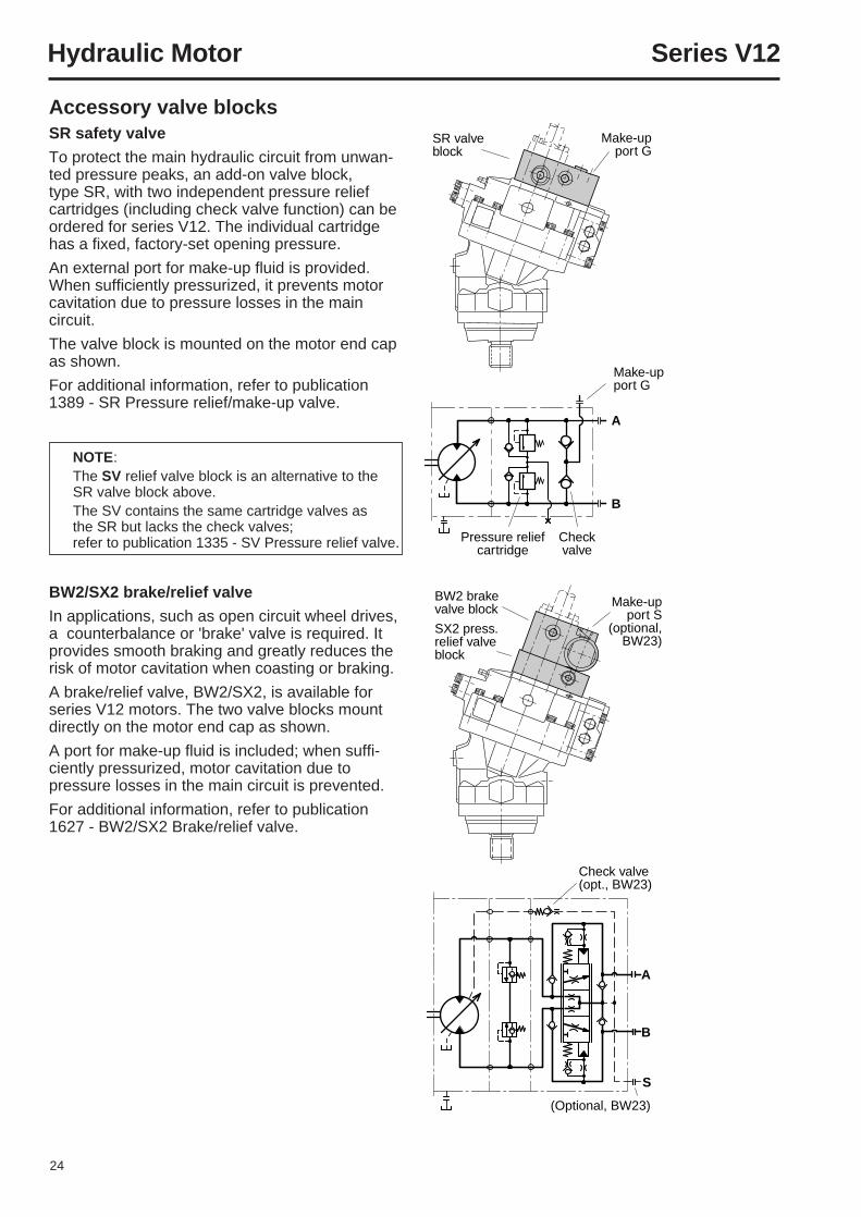
BW2 brake valve block Make-up
port S(optional,
BW23) SX2 press. relief valveblock
A
B
S
Check valve (opt., BW23)
(Optional, BW23)
Accessory valve blocksSR safety valve
To protect the main hydraulic circuit from unwan-ted pressure peaks, an add-on valve block,type SR, with two independent pressure reliefcartridges (including check valve function) can beordered for series V12. The individual cartridgehas a fixed, factory-set opening pressure.
An external port for make-up fluid is provided.When sufficiently pressurized, it prevents motorcavitation due to pressure losses in the maincircuit.
The valve block is mounted on the motor end capas shown.
For additional information, refer to publication1389 - SR Pressure relief/make-up valve.
NOTE:The SV relief valve block is an alternative to theSR valve block above.The SV contains the same cartridge valves asthe SR but lacks the check valves;refer to publication 1335 - SV Pressure relief valve.
BW2/SX2 brake/relief valve
In applications, such as open circuit wheel drives,a counterbalance or 'brake' valve is required. Itprovides smooth braking and greatly reduces therisk of motor cavitation when coasting or braking.
A brake/relief valve, BW2/SX2, is available forseries V12 motors. The two valve blocks mountdirectly on the motor end cap as shown.
A port for make-up fluid is included; when suffi-ciently pressurized, motor cavitation due topressure losses in the main circuit is prevented.
For additional information, refer to publication1627 - BW2/SX2 Brake/relief valve.
Make-up port G
Pressure reliefcartridge
Checkvalve
A
B
SR valve block
Make-upport G
25
Hydraulic Motor Series V12
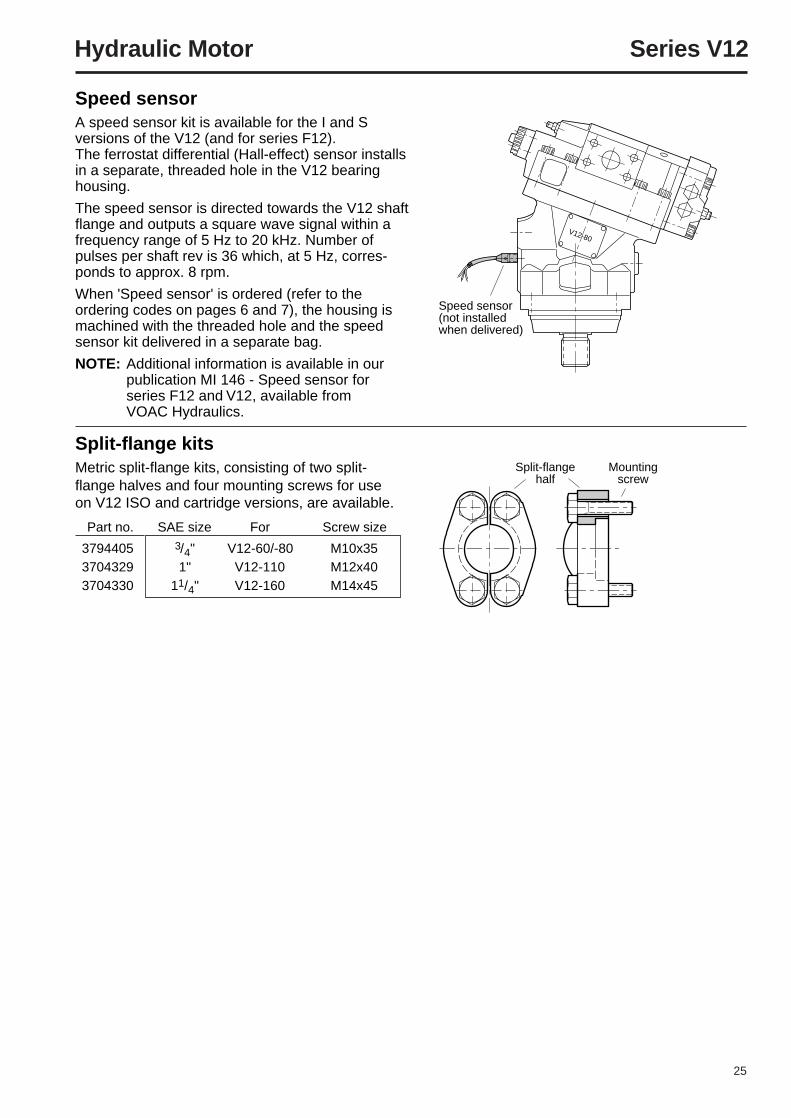
V12-80
Speed sensor(not installed when delivered)
Split-flange kitsMetric split-flange kits, consisting of two split-flange halves and four mounting screws for useon V12 ISO and cartridge versions, are available.
Part no. SAE size For Screw size
3794405 3/4" V12-60/-80 M10x353704329 1" V12-110 M12x403704330 11/4" V12-160 M14x45
Speed sensorA speed sensor kit is available for the I and Sversions of the V12 (and for series F12).The ferrostat differential (Hall-effect) sensor installsin a separate, threaded hole in the V12 bearinghousing.
The speed sensor is directed towards the V12 shaftflange and outputs a square wave signal within afrequency range of 5 Hz to 20 kHz. Number ofpulses per shaft rev is 36 which, at 5 Hz, corres-ponds to approx. 8 rpm.
When 'Speed sensor' is ordered (refer to theordering codes on pages 6 and 7), the housing ismachined with the threaded hole and the speedsensor kit delivered in a separate bag.
NOTE: Additional information is available in ourpublication MI 146 - Speed sensor forseries F12 and V12, available fromVOAC Hydraulics.
Split-flangehalf
Mountingscrew
26
Hydraulic Motor Series V12
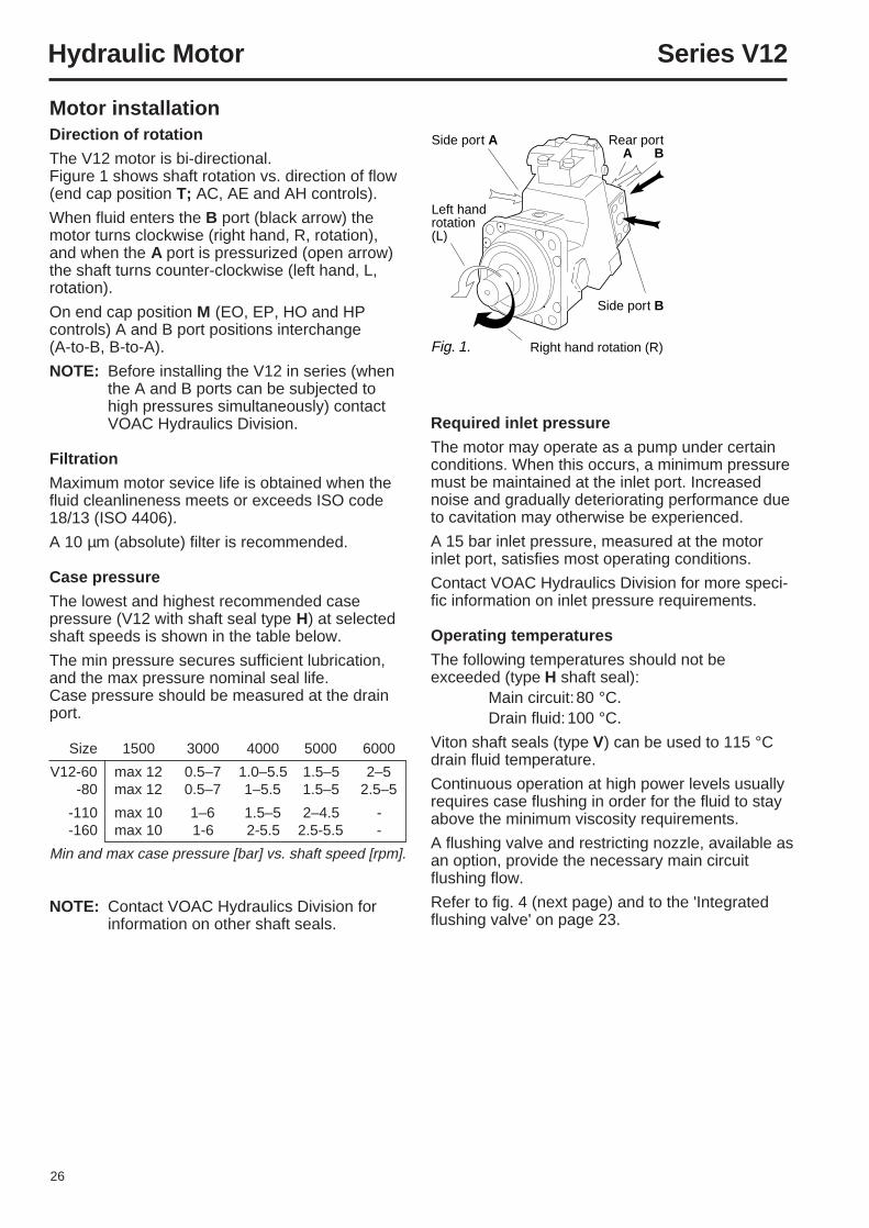
Fig. 1.
Side port A
Side port B
Right hand rotation (R)
Rear portA B
Left handrotation (L)
Motor installationDirection of rotation
The V12 motor is bi-directional.Figure 1 shows shaft rotation vs. direction of flow(end cap position T; AC, AE and AH controls).
When fluid enters the B port (black arrow) themotor turns clockwise (right hand, R, rotation),and when the A port is pressurized (open arrow)the shaft turns counter-clockwise (left hand, L,rotation).
On end cap position M (EO, EP, HO and HPcontrols) A and B port positions interchange(A-to-B, B-to-A).
NOTE: Before installing the V12 in series (whenthe A and B ports can be subjected tohigh pressures simultaneously) contactVOAC Hydraulics Division.
Filtration
Maximum motor sevice life is obtained when thefluid cleanlineness meets or exceeds ISO code18/13 (ISO 4406).
A 10 µm (absolute) filter is recommended.
Case pressure
The lowest and highest recommended casepressure (V12 with shaft seal type H) at selectedshaft speeds is shown in the table below.
The min pressure secures sufficient lubrication,and the max pressure nominal seal life.Case pressure should be measured at the drainport.
Size 1500 3000 4000 5000 6000
V12-60 max 12 0.5–7 1.0–5.5 1.5–5 2–5-80 max 12 0.5–7 1–5.5 1.5–5 2.5–5
-110 max 10 1–6 1.5–5 2–4.5 --160 max 10 1-6 2-5.5 2.5-5.5 -
Min and max case pressure [bar] vs. shaft speed [rpm].
NOTE: Contact VOAC Hydraulics Division forinformation on other shaft seals.
Required inlet pressure
The motor may operate as a pump under certainconditions. When this occurs, a minimum pressuremust be maintained at the inlet port. Increasednoise and gradually deteriorating performance dueto cavitation may otherwise be experienced.
A 15 bar inlet pressure, measured at the motorinlet port, satisfies most operating conditions.
Contact VOAC Hydraulics Division for more speci-fic information on inlet pressure requirements.
Operating temperatures
The following temperatures should not beexceeded (type H shaft seal):
Main circuit:80 °C.Drain fluid:100 °C.
Viton shaft seals (type V) can be used to 115 °Cdrain fluid temperature.
Continuous operation at high power levels usuallyrequires case flushing in order for the fluid to stayabove the minimum viscosity requirements.
A flushing valve and restricting nozzle, available asan option, provide the necessary main circuitflushing flow.
Refer to fig. 4 (next page) and to the 'Integratedflushing valve' on page 23.
27
Hydraulic Motor Series V12
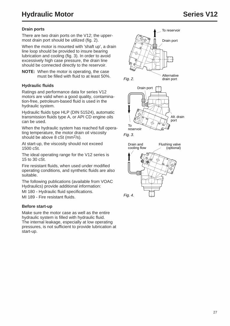
To reservoir
To reservoir
Drain port
Drain port
Alternativedrain port
Alt. drain port
Drain andcooling flow
Flushing valve(optional)
Fig. 2.
Fig. 3.
Fig. 4.
Drain ports
There are two drain ports on the V12; the upper-most drain port should be utilized (fig. 2).
When the motor is mounted with 'shaft up', a drainline loop should be provided to insure bearinglubrication and cooling (fig. 3). In order to avoidexcessively high case pressure, the drain lineshould be connected directly to the reservoir.
NOTE: When the motor is operating, the casemust be filled with fluid to at least 50%.
Hydraulic fluids
Ratings and performance data for series V12motors are valid when a good quality, contamina-tion-free, petroleum-based fluid is used in thehydraulic system.
Hydraulic fluids type HLP (DIN 51524), automatictransmission fluids type A, or API CD engine oilscan be used.
When the hydraulic system has reached full opera-ting temperature, the motor drain oil viscosityshould be above 8 cSt (mm2/s).
At start-up, the viscosity should not exceed1500 cSt.
The ideal operating range for the V12 series is15 to 30 cSt.
Fire resistant fluids, when used under modifiedoperating conditions, and synthetic fluids are alsosuitable.
The following publications (available from VOACHydraulics) provide additional information:MI 180 - Hydraulic fluid specifications.MI 189 - Fire resistant fluids.
Before start-up
Make sure the motor case as well as the entirehydraulic system is filled with hydraulic fluid.The internal leakage, especially at low operatingpressures, is not sufficient to provide lubrication atstart-up.
Parker Hannifin ABVOAC Hydraulics DivisionS-461 82 TrollhättanSwedenTel +46 520 986 00Fax +46 520 371 05
Catalog 9129 8217-02Ed. 1256-9825 GB
Please contact our sales representative: