hydraulic filtration & contamination control products kataloogid/filtrations/zf 02 hydr... ·...
TRANSCRIPT
Hydraulic Filtration & ContaminationControl Products
Brochure: FDHB200UK (Medium Pressure Section)
Parker Hannifin
Filter Division Europe
FDHB200UK.
• Consistent quality
• Technical innovation
• Premier customer service
Parkers technical resources provide the
correct filtration technologies that conform
to your requirements. That’s why thousands
of manufacturers and equipment users around
the world rely on Parker Filtration products
and people.
Worldwide Sales
and Service
Parker Filtration’s global reputation as a reliable
supplier of superior filtration products is the result
of a focused and integrated development and
manufacturing system.
Parker Filtration consolidates quality filtration
products, manufactured by process filtration, air
and gas filtration and separation, fuel conditioning
and filtration, hydraulic and lubrication filtration,
fluid power products and fluid condition monitoring
equipment into one broad-based range that
covers many markets and most applications,
as detailed here.
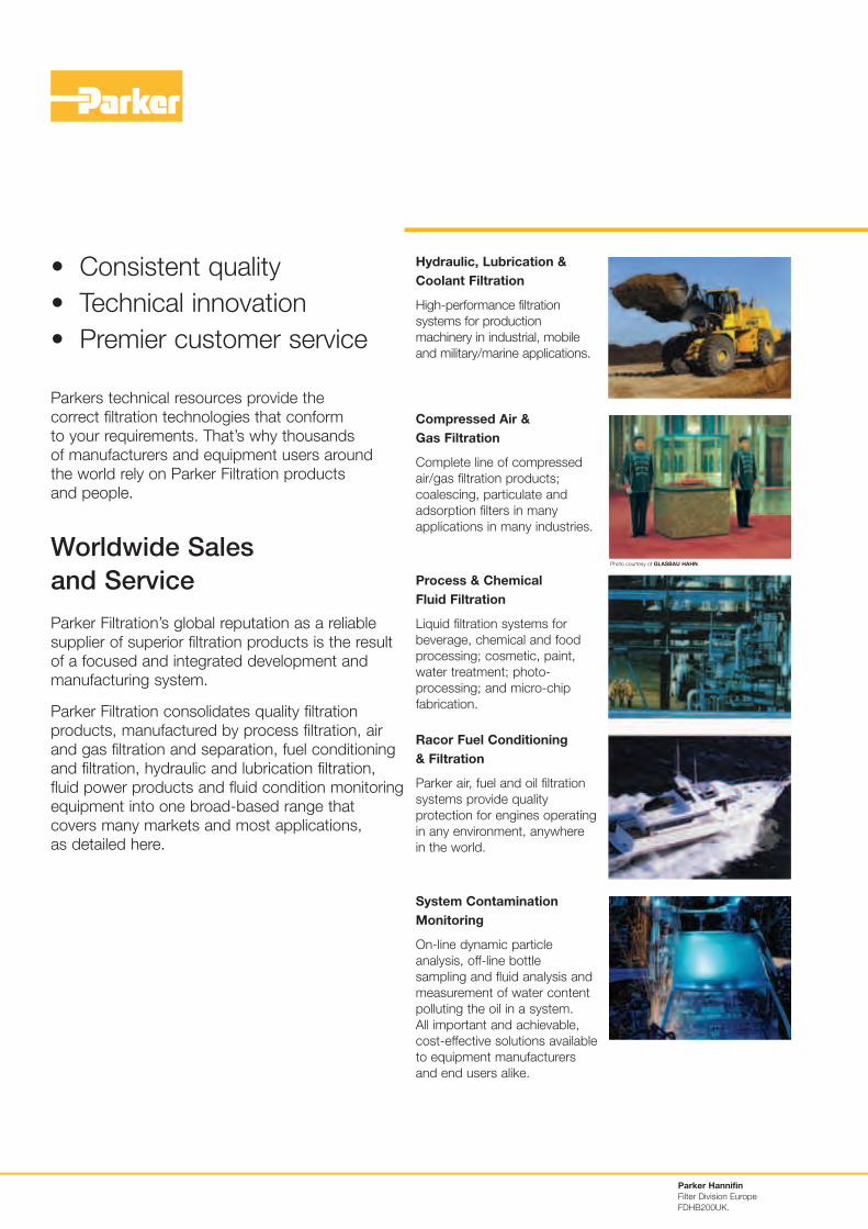
Hydraulic, Lubrication &
Coolant Filtration
High-performance filtration
systems for production
machinery in industrial, mobile
and military/marine applications.
Compressed Air &
Gas Filtration
Complete line of compressed
air/gas filtration products;
coalescing, particulate and
adsorption filters in many
applications in many industries.
Process & Chemical
Fluid Filtration
Liquid filtration systems for
beverage, chemical and food
processing; cosmetic, paint,
water treatment; photo-
processing; and micro-chip
fabrication.
Racor Fuel Conditioning
& Filtration
Parker air, fuel and oil filtration
systems provide quality
protection for engines operating
in any environment, anywhere
in the world.
System Contamination
Monitoring
On-line dynamic particle
analysis, off-line bottle
sampling and fluid analysis and
measurement of water content
polluting the oil in a system.
All important and achievable,
cost-effective solutions available
to equipment manufacturers
and end users alike.
Photo courtesy of GLASBAU HAHN.
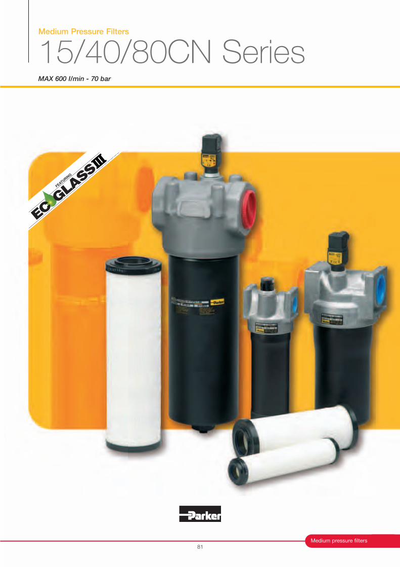
Medium Pressure Filters
15/40/80CN SeriesMAX 600 I/min - 70 bar
Medium pressure filters
FEATURIN
G
81
Medium Pressure Filters
15/40/80CN Series
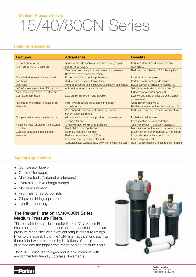
Typical Applications
Compressor lube oil
Off-line filter loops
Machine tools (Automotive standard)
Hydrostatic drive charge pumps
Mobile equipment
Pilot lines for servo controls
Oil patch drilling equipment
Injection moulding
The Parker Filtration 15/40/80CN SeriesMedium Pressure Filters.
This partial list of applications for Parker “CN” Series Filters
has a common factor, the need for an economical, medium
pressure range filter with excellent fatigue pressure ratings.
Prior to the availability of the “CN” filter, applications such as
those listed were restricted by limitations of a spin-on can,
or forced into the higher-cost range of high pressure filters.
The “CN” Series fills this gap and is now available with
environmentally friendly Ecoglass III elements.
Features & Benefits
Parker Hannifin
Filter Division Europe
FDHB200UK. Section 10
82
Features
56 bar fatigue rating
(eight times that of a spin-on)
Diametral (side) seal between head
and bowl
Dust seal
40CN-2 meets automotive HF3 standard
15CN meets automotive HF2 standard
Cast aluminium head
Reinforced Microglass III replacement
elements
Complete performance data disclosure
Visual, electrical or electronic indicators
available
Coreless Ecoglass III replacement
elements
Advantages
Ability to provide reliable service under tough cyclic
operating conditions
Can be utilised in applications where high pressure
filters may have been only option
Proven reliability in cyclic applications
Reduced importance of bowl torque
Prevents contamination from building up on bowl/head threads
Automotive industry acceptance
Low profile, lightweight and durable
Multi-layered design produced high capacity
and efficiency
Wire support reduces pleat bunching, keeps
performance consistent
All pertinent information is provided in an easy-to-
compare format
Check element condition at a glance
Right style for the application
No metal content in element
Reduced overall weight of 50%
Easy compaction of used elements
Conversion kits available: new bowl with permanent core
Benefits
Reduced downtime due to premature
filter failures
Reduced costs, better “fit” for the application
No downtime, no leaks
Performs with “real world” service
Easier service, eliminates thread galling
Satisfies specifications without need for
further testing and/or approval
Less weight, smaller envelop and cleaner
appearance
Great performance value
Reliable performance throughout element life
Reduces downtime, maximises element life
No hidden deficiencies
Easy selection of proper filtration
Optimise element life, prevent bypassing
Matches your system electrical connections
Environmentally friendly disposal by incineration
Lower element replacement costs
Lower disposal cost
Retrofit coreless design to housings already installed
Medium pressure filters
Specification
Flow fatigue characteristics:Filter media is supported so that the optimal fatigue life is achieved(ISO 3724).
Microglass III (available by request)Supported with epoxy coated metal wire mesh, end cap materialreinforced composite and metal inner core. Collapse rating 20 bar (ISO 2941).
Ecoglass IIISupported with plastic net, end cap material reinforced composite. No metal parts. Collapse rating 10 bar (ISO 2941).Filter element can only be used together with bowl including Eco-adaptor.Note: Ecoglass III contributes to ISO 14001 quality.
Indicator options:- visual M3.- electrical T1.- electronic F1(PNP).- electronic F2(NPN).For indicator details see catalogue section 6.
Weights (kg):Model Length 1 Length 215CN 1.1 1.640CN 2.0 2.580CN 5.6 6.9
Fluid compatibility:Suitable for use with mineral and vegetable oils, and some syntheticoils. For other fluids, please consult Parker Filtration.
83
15CN
40CN
80CN
156.6
(6.17)
170.8
(6.73)
280.9
(11.06)
250.7
(9.87)
262.4
(10.33)
401.6
(15.81)
46.5
(1.83)
62.0
(2.44)
77.7
(3.06)
25.4
(1.09)
32.6
(1.28)
49.5
(1.95)
71.1
(2.80)
107.2
(4.22)
124.8
(4.91)
85.9
(3.38)
127.0
(5.00)
158.7
(6.25)
73.2
(2.88)
111.0
(4.37)
82.6
(3.25)
82.6
(3.25)
121.9
(4.80)
151.4
(5.96)
38.1
(1.50)
62.0
(2.44)
101.6
(4.00)
22.9
(0.90)
31.8
(1.25)
41.1
(1.62)
42.9
(1.69)
58.8
(2.32)
79.4
(3.12)
36.6
(1.44)
60.2
(2.37)
41.3
(1.63)
53
53
69
4xM6-1.0x7.9 deep
4xM8-1.25x13 deep
4xM8-1.25x16 deep
20-27 Nm
57-68 Nm
80-95 Nm
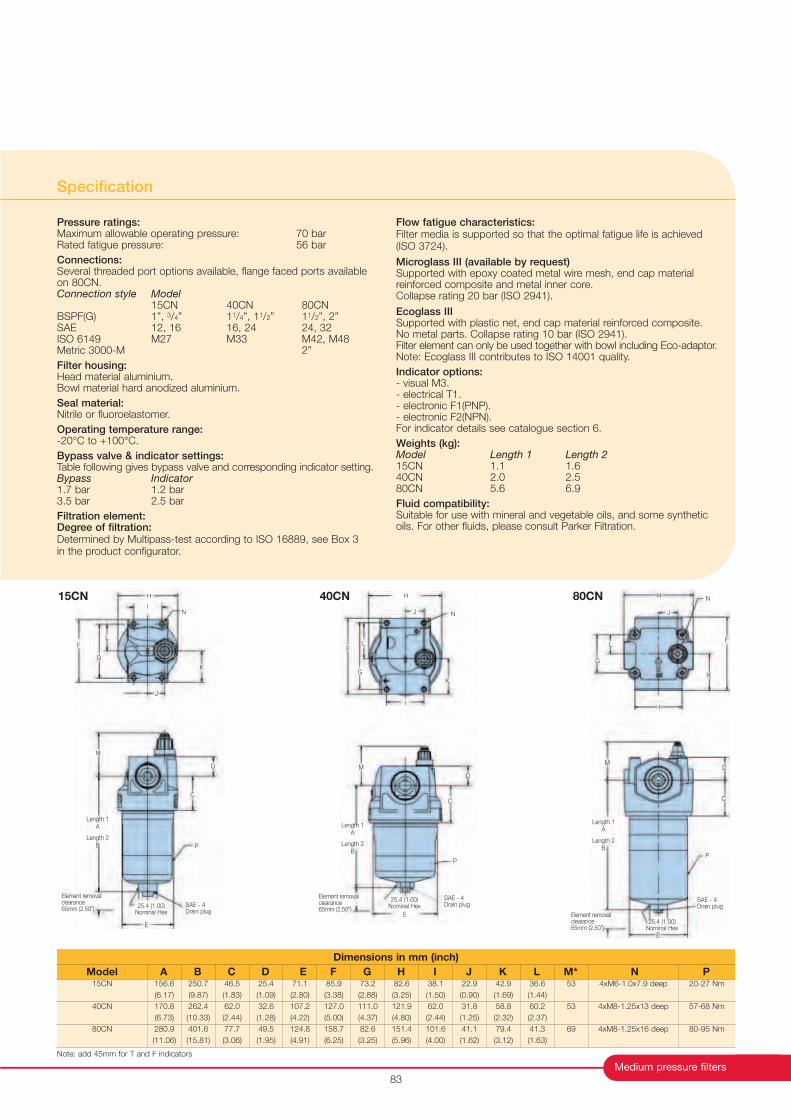
Dimensions in mm (inch)
Model A B C D E F G H I J K L M* N P
H
I
F
G
L
J
K
N
D
C
E
Length 1A
Length 2B P
SAE - 4Drain plug
Element removalclearance65mm (2.50”)
25.4 (1.00)Nominal Hex
H
J
F
G
N
K
I
L
15CN 80CN40CN
Length 1A
Length 2B
Element removalclearance65mm (2.50”)
SAE - 4Drain plug
25.4 (1.00)Nominal Hex
P
D
C
H
J
G
L
K
F
I
N
SAE - 4Drain plug
P
25.4 (1.00)Nominal Hex
E
C
DM
Length 1A
Length 2B
Element removalclearance65mm (2.50”)
M
M
E
Note: add 45mm for T and F indicators
Pressure ratings:Maximum allowable operating pressure: 70 barRated fatigue pressure: 56 bar
Connections:Several threaded port options available, flange faced ports availableon 80CN.Connection style Model
15CN 40CN 80CNBSPF(G) 1”, 3/4” 11/4”, 11/2” 11/2”, 2”SAE 12, 16 16, 24 24, 32ISO 6149 M27 M33 M42, M48Metric 3000-M 2”
Filter housing:Head material aluminium.Bowl material hard anodized aluminium.
Seal material:Nitrile or fluoroelastomer.
Operating temperature range:-20°C to +100°C.
Bypass valve & indicator settings:Table following gives bypass valve and corresponding indicator setting.Bypass Indicator1.7 bar 1.2 bar3.5 bar 2.5 bar
Filtration element:Degree of filtration:Determined by Multipass-test according to ISO 16889, see Box 3 in the product configurator.
Medium Pressure Filters
15/40/80CN Series
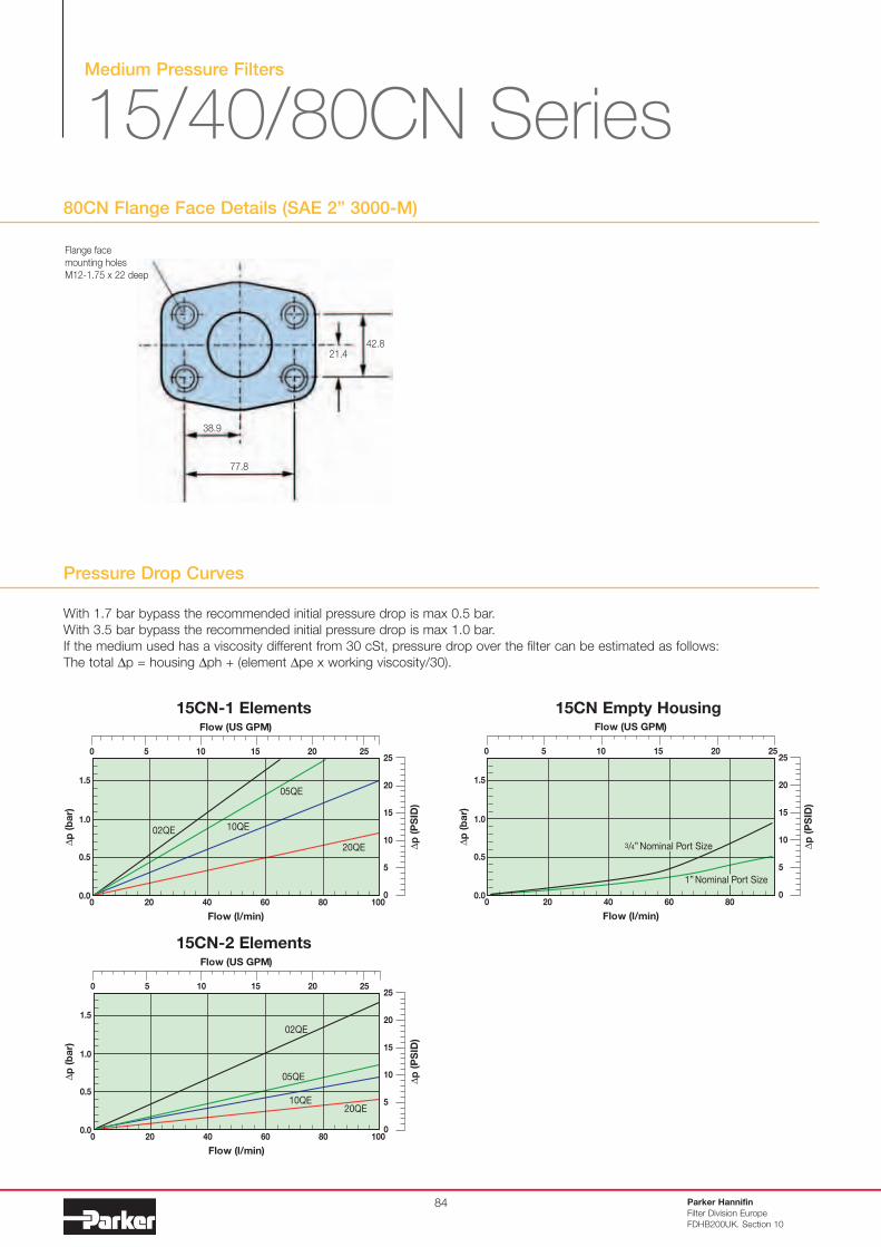
80CN Flange Face Details (SAE 2” 3000-M)
Parker Hannifin
Filter Division Europe
FDHB200UK. Section 10
84
38.9
77.8
21.442.8
Flange face
mounting holes
M12-1.75 x 22 deep
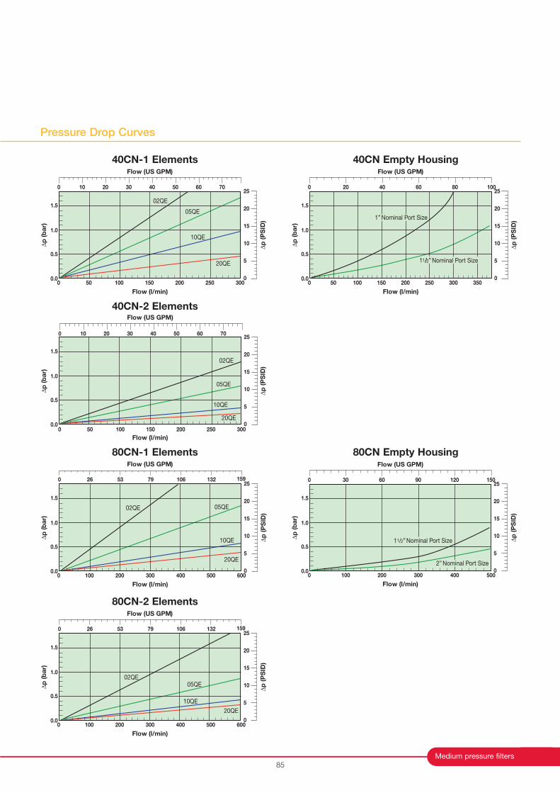
Pressure Drop Curves
With 1.7 bar bypass the recommended initial pressure drop is max 0.5 bar.
With 3.5 bar bypass the recommended initial pressure drop is max 1.0 bar.
If the medium used has a viscosity different from 30 cSt, pressure drop over the filter can be estimated as follows:
The total ∆p = housing ∆ph + (element ∆pe x working viscosity/30).
15CN-2 Elements
15CN-1 Elements 15CN Empty Housing
25
20
15
5
0
10
Flow (US GPM)
Flow (l/min)
20 40 600.0
∆p
(b
ar)
0.5
1.0
1.5
0
10 15 20 2550
80 100
02QE
05QE
20QE10QE
∆p
(P
SID
)
25
20
15
5
0
10
Flow (US GPM)
Flow (l/min)
20 40 600.0
∆p
(b
ar)
0.5
1.0
1.5
0
0 5 10 15 20 25
80
3/4” Nominal Port Size
1” Nominal Port Size
∆p
(P
SID
)
25
20
15
5
0
10
Flow (US GPM)
Flow (l/min)
20 40 600.0
∆p
(b
ar)
0.5
1.0
1.5
0
10 15 20 2550
80 100
02QE
05QE
20QE
10QE
∆p
(P
SID
)
Medium pressure filters
Pressure Drop Curves
85
80CN-1 Elements
80CN-2 Elements
40CN-2 Elements
80CN Empty Housing
25
20
15
5
0
10
Flow (US GPM)
Flow (l/min)
0.0
∆p
(b
ar)
0.5
1.0
1.5
02QE 05QE
20QE
10QE ∆p
(P
SID
)
0 100 200 300 400 500 600
0 26 53 79 106 132 159
25
20
15
5
0
10
Flow (US GPM)
Flow (l/min)
0.0
∆p
(b
ar)
0.5
1.0
1.5
02QE05QE
20QE
10QE
∆p
(P
SID
)
0 100 200 300 400 500 600
0 26 53 79 106 132 159
25
20
15
5
0
10
Flow (US GPM)
Flow (l/min)
0.0
∆p
(b
ar)
0.5
1.0
1.5
02QE
05QE
20QE
10QE
∆p
(P
SID
)
0 70
50 100 150 200 250 3000
10 20 30 40 50 60
40CN Empty Housing
25
20
15
5
0
10
0 20 40 60 100
Flow (US GPM)
Flow (l/min)
50 100 150 200 250 300 3500.0
∆p
(b
ar)
0.5
1.0
1.5
0
80
11/2” Nominal Port Size
1” Nominal Port Size
∆p
(P
SID
)
25
20
15
5
0
10
0 30 60 90 150
Flow (US GPM)
Flow (l/min)
100 200 300 4000.0
∆p
(b
ar)
0.5
1.0
1.5
0
120
500
11/2” Nominal Port Size
2” Nominal Port Size
∆p
(P
SID
)
40CN-1 Elements
25
20
15
5
0
10
0 70
Flow (US GPM)
Flow (l/min)
50 100 150 200 250 3000.0
∆p
(b
ar)
0.5
1.0
1.5
0
10 20 30 40 50 60
02QE
05QE
20QE
10QE
∆p
(P
SID
)
Medium Pressure Filters
15/40/80CN Series
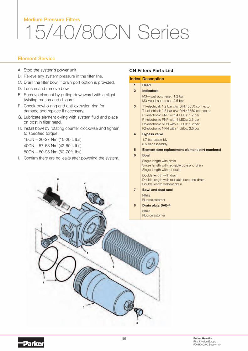
Element Service
8
3
2
1
6
5
4
7
A. Stop the system’s power unit.
B. Relieve any system pressure in the filter line.
C. Drain the filter bowl if drain port option is provided.
D. Loosen and remove bowl.
E. Remove element by pulling downward with a slight
twisting motion and discard.
F. Check bowl o-ring and anti-extrusion ring for
damage and replace if necessary.
G. Lubricate element o-ring with system fluid and place
on post in filter head.
H. Install bowl by rotating counter clockwise and tighten
to specified torque.
15CN – 20-27 Nm (15-20ft. lbs)
40CN – 57-68 Nm (42-50ft. lbs)
80CN – 80-95 Nm (60-70ft. lbs)
I. Confirm there are no leaks after powering the system.
Parker Hannifin
Filter Division Europe
FDHB200UK. Section 10
86
Head
Indicators
M3-visual auto reset: 1.2 bar
M3-visual auto reset: 2.5 bar
T1-electrical: 1.2 bar c/w DIN 43650 connector
T1-electrical: 2.5 bar c/w DIN 43650 connector
F1-electronic PNP with 4 LEDs: 1.2 bar
F1-electronic PNP with 4 LEDs: 2.5 bar
F2-electronic NPN with 4 LEDs: 1.2 bar
F2-electronic NPN with 4 LEDs: 2.5 bar
Bypass valve
1.7 bar assembly
3.5 bar assembly
Element (see replacement element part numbers)
Bowl
Single length with drain
Single length with reusable core and drain
Single length without drain
Double length with drain
Double length with reusable core and drain
Double length without drain
Bowl and dust seal
Nitrile
Fluoroelastomer
Drain plug: SAE-4
Nitrile
Fluoroelastomer
1
2
3
4
5
6
7
8
Index Description
CN Filters Parts List
Medium pressure filters
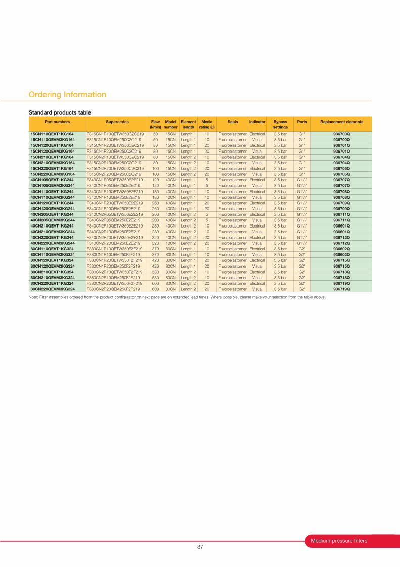
Ordering Information
87
Note: Filter assemblies ordered from the product configurator on next page are on extended lead times. Where possible, please make your selection from the table above.
Part numbers
15CN110QEVT1KG164
15CN110QEVM3KG164
15CN120QEVT1KG164
15CN120QEVM3KG164
15CN210QEVT1KG164
15CN210QEVM3KG164
15CN220QEVT1KG164
15CN220QEVM3KG164
40CN105QEVT1KG244
40CN105QEVM3KG244
40CN110QEVT1KG244
40CN110QEVM3KG244
40CN120QEVT1KG244
40CN120QEVM3KG244
40CN205QEVT1KG244
40CN205QEVM3KG244
40CN210QEVT1KG244
40CN210QEVM3KG244
40CN220QEVT1KG244
40CN220QEVM3KG244
80CN110QEVT1KG324
80CN110QEVM3KG324
80CN120QEVT1KG324
80CN120QEVM3KG324
80CN210QEVT1KG324
80CN210QEVM3KG324
80CN220QEVT1KG324
80CN220QEVM3KG324
Supercedes
F315CN1R10QETW350C2C219
F315CN1R10QEM250C2C219
F315CN1R20QETW350C2C219
F315CN1R20QEM250C2C219
F315CN2R10QETW350C2C219
F315CN2R10QEM250C2C219
F315CN2R20QETW350C2C219
F315CN2R20QEM250C2C219
F340CN1R05QETW350E2E219
F340CN1R05QEM250E2E219
F340CN1R10QETW350E2E219
F340CN1R10QEM250E2E219
F340CN1R20QETW350E2E219
F340CN1R20QEM250E2E219
F340CN2R05QETW350E2E219
F340CN2R05QEM250E2E219
F340CN2R10QETW350E2E219
F340CN2R10QEM250E2E219
F340CN2R20QETW350E2E219
F340CN2R20QEM250E2E219
F380CN1R10QETW350F2F219
F380CN1R10QEM250F2F219
F380CN1R20QETW350F2F219
F380CN1R20QEM250F2F219
F380CN2R10QETW350F2F219
F380CN2R10QEM250F2F219
F380CN2R20QETW350F2F219
F380CN2R20QEM250F2F219
Flow
(l/min)
50
50
80
80
80
80
100
100
120
120
180
180
260
260
200
200
280
280
320
320
370
370
420
420
530
530
600
600
Model
number
15CN
15CN
15CN
15CN
15CN
15CN
15CN
15CN
40CN
40CN
40CN
40CN
40CN
40CN
40CN
40CN
40CN
40CN
40CN
40CN
80CN
80CN
80CN
80CN
80CN
80CN
80CN
80CN
Element
length
Length 1
Length 1
Length 1
Length 1
Length 2
Length 2
Length 2
Length 2
Length 1
Length 1
Length 1
Length 1
Length 1
Length 1
Length 2
Length 2
Length 2
Length 2
Length 2
Length 2
Length 1
Length 1
Length 1
Length 1
Length 2
Length 2
Length 2
Length 2
Media
rating (µ)
10
10
20
20
10
10
20
20
5
5
10
10
20
20
5
5
10
10
20
20
10
10
20
20
10
10
20
20
Seals
Fluoroelastomer
Fluoroelastomer
Fluoroelastomer
Fluoroelastomer
Fluoroelastomer
Fluoroelastomer
Fluoroelastomer
Fluoroelastomer
Fluoroelastomer
Fluoroelastomer
Fluoroelastomer
Fluoroelastomer
Fluoroelastomer
Fluoroelastomer
Fluoroelastomer
Fluoroelastomer
Fluoroelastomer
Fluoroelastomer
Fluoroelastomer
Fluoroelastomer
Fluoroelastomer
Fluoroelastomer
Fluoroelastomer
Fluoroelastomer
Fluoroelastomer
Fluoroelastomer
Fluoroelastomer
Fluoroelastomer
Indicator
Electrical
Visual
Electrical
Visual
Electrical
Visual
Electrical
Visual
Electrical
Visual
Electrical
Visual
Electrical
Visual
Electrical
Visual
Electrical
Visual
Electrical
Visual
Electrical
Visual
Electrical
Visual
Electrical
Visual
Electrical
Visual
Bypass
settings
3.5 bar
3.5 bar
3.5 bar
3.5 bar
3.5 bar
3.5 bar
3.5 bar
3.5 bar
3.5 bar
3.5 bar
3.5 bar
3.5 bar
3.5 bar
3.5 bar
3.5 bar
3.5 bar
3.5 bar
3.5 bar
3.5 bar
3.5 bar
3.5 bar
3.5 bar
3.5 bar
3.5 bar
3.5 bar
3.5 bar
3.5 bar
3.5 bar
Replacement elements
936700Q
936700Q
936701Q
936701Q
936704Q
936704Q
936705Q
936705Q
936707Q
936707Q
936708Q
936708Q
936709Q
936709Q
936711Q
936711Q
936601Q
936601Q
936712Q
936712Q
936602Q
936602Q
936715Q
936715Q
936718Q
936718Q
936719Q
936719Q
Ports
G1"
G1"
G1"
G1"
G1"
G1"
G1"
G1"
G11/2"
G11/2"
G11/2"
G11/2"
G11/2"
G11/2"
G11/2"
G11/2"
G11/2"
G11/2"
G11/2"
G11/2"
G2"
G2"
G2"
G2"
G2"
G2"
G2"
G2"
Standard products table
Medium Pressure Filters
15/40/80CN Series
Parker Hannifin
Filter Division Europe
FDHB200UK. Section 10
88
* Fluoroelastomers are available under various registered trademarks,
including Viton (a registered trademark of DuPont) and Fluorel (a registered
trademark of 3M)
02Q
928935Q
928953Q
926696Q
926697Q
932656Q
932662Q
05Q
G04041Q
G04169Q
G04048Q
G04167Q
932657Q
932663Q
10Q
928934Q
928952Q
926835Q
926837Q
932658Q
932664Q
20Q
930367Q
930368Q
930099Q
930118Q
929899Q
929923Q
Model
15CN-1
15CN-2
40CN-1
40CN-2
80CN-1
80CN-2
Elements with nitrile seals
02Q
932610Q
932616Q
926716Q
926717Q
932659Q
932665Q
05Q
G04189Q
G04190Q
G04191Q
G04192Q
932660Q
932666Q
10Q
932612Q
932618Q
926836Q
926838Q
832661Q
932667Q
20Q
930369Q
930370Q
930100Q
930119Q
929903Q
929927Q
Model
15CN-1
15CN-2
40CN-1
40CN-2
80CN-1
80CN-2
Elements with Fluoroelastomer seals
02QE
10
30
60
80
150
180
05QE
30
70
120
200
300
420
10QE
50
80
180
280
370
530
20QE
80
100
260
320
420
600
Housing, port size
15CN-1, G1
15CN-2, G1
40CN-1, G11/2
40CN-2, G11/2
80CN-1, G2
80CN-2, G2
Nominal flow (l/min) for filter assembly at viscosity 30cSt
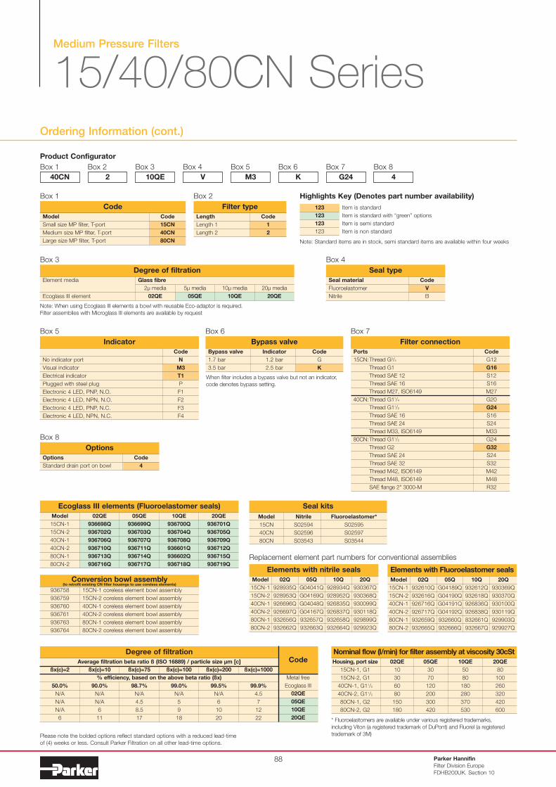
Ordering Information (cont.)
Product Configurator
Box 1
Code
1
2
Length
Length 1
Length 2
Filter type
Box 2
40CN
Box 2
2
Box 3
10QE
Box 4
V
Box 5
M3
Box 6
K
Box 7
G24
Box 8
4
Please note the bolded options reflect standard options with a reduced lead-time
of (4) weeks or less. Consult Parker Filtration on all other lead-time options.
Code
V
B
Seal material
Fluoroelastomer
Nitrile
Seal type
Box 4
Bypass valve
1.7 bar
3.5 bar
Bypass valve
Indicator
1.2 bar
2.5 bar
Code
G
K
Box 6
Code
N
M3
T1
P
F1
F2
F3
F4
No indicator port
Visual indicator
Electrical indicator
Plugged with steel plug
Electronic 4 LED, PNP, N.O.
Electronic 4 LED, NPN, N.O.
Electronic 4 LED, PNP, N.C.
Electronic 4 LED, NPN, N.C.
Indicator
Box 5
Code
G12
G16
S12
S16
M27
G20
G24
S16
S24
M33
G24
G32
S24
S32
M42
M48
R32
Ports
15CN:Thread G3/4
Thread G1
Thread SAE 12
Thread SAE 16
Thread M27, ISO6149
40CN:Thread G11/4
Thread G11/2
Thread SAE 16
Thread SAE 24
Thread M33, ISO6149
80CN:Thread G11/2
Thread G2
Thread SAE 24
Thread SAE 32
Thread M42, ISO6149
Thread M48, ISO6149
SAE flange 2" 3000-M
Filter connection
Box 7
Code
4
Options
Standard drain port on bowl
Options
Box 8
Code
15CN
40CN
80CN
Model
Small size MP filter, T-port
Medium size MP filter, T-port
Large size MP filter, T-port
Code
Box 1
Note: When using Ecoglass III elements a bowl with reusable Eco-adaptor is required.
Filter assemblies with Microglass III elements are available by request
Model
15CN-1
15CN-2
40CN-1
40CN-2
80CN-1
80CN-2
Ecoglass III elements (Fluoroelastomer seals)
02QE
936698Q
936702Q
936706Q
936710Q
936713Q
936716Q
05QE
936699Q
936703Q
936707Q
936711Q
936714Q
936717Q
10QE
936700Q
936704Q
936708Q
936601Q
936602Q
936718Q
20QE
936701Q
936705Q
936709Q
936712Q
936715Q
936719Q
936758
936759
936760
936761
936763
936764
Conversion bowl assembly
15CN-1 coreless element bowl assembly
15CN-2 coreless element bowl assembly
40CN-1 coreless element bowl assembly
40CN-2 coreless element bowl assembly
80CN-1 coreless element bowl assembly
80CN-2 coreless element bowl assembly
(to retrofit existing CN filter housings to use coreless elements)
Model
15CN
40CN
80CN
Seal kits
Nitrile
S02594
S02596
S03543
Fluoroelastomer*
S02595
S02597
S03544
Replacement element part numbers for conventional assemblies
When filter includes a bypass valve but not an indicator,
code denotes bypass setting.
Item is standard
Item is standard with “green” options
Item is semi standard
Item is non standard
123
123
123
123
Highlights Key (Denotes part number availability)
Note: Standard items are in stock, semi standard items are available within four weeks
Box 3
Element media
Ecoglass III element
20µ media
20QE
10µ media
10QE
5µ media
05QE
2µ media
02QE
Glass fibre
Degree of filtration
Average filtration beta ratio ß (ISO 16889) / particle size µm [c]
% efficiency, based on the above beta ratio (ßx)
ßx(c)=2
50.0%
N/A
N/A
N/A
6
Degree of filtrationCode
ßx(c)=10
90.0%
N/A
N/A
6
11
ßx(c)=75
98.7%
N/A
4.5
8.5
17
ßx(c)=100
99.0%
N/A
5
9
18
ßx(c)=200
99.5%
N/A
6
10
20
ßx(c)=1000
99.9%
4.5
7
12
22
02QE
05QE
10QE
20QE
Metal free
Ecoglass III
Medium Pressure Filters
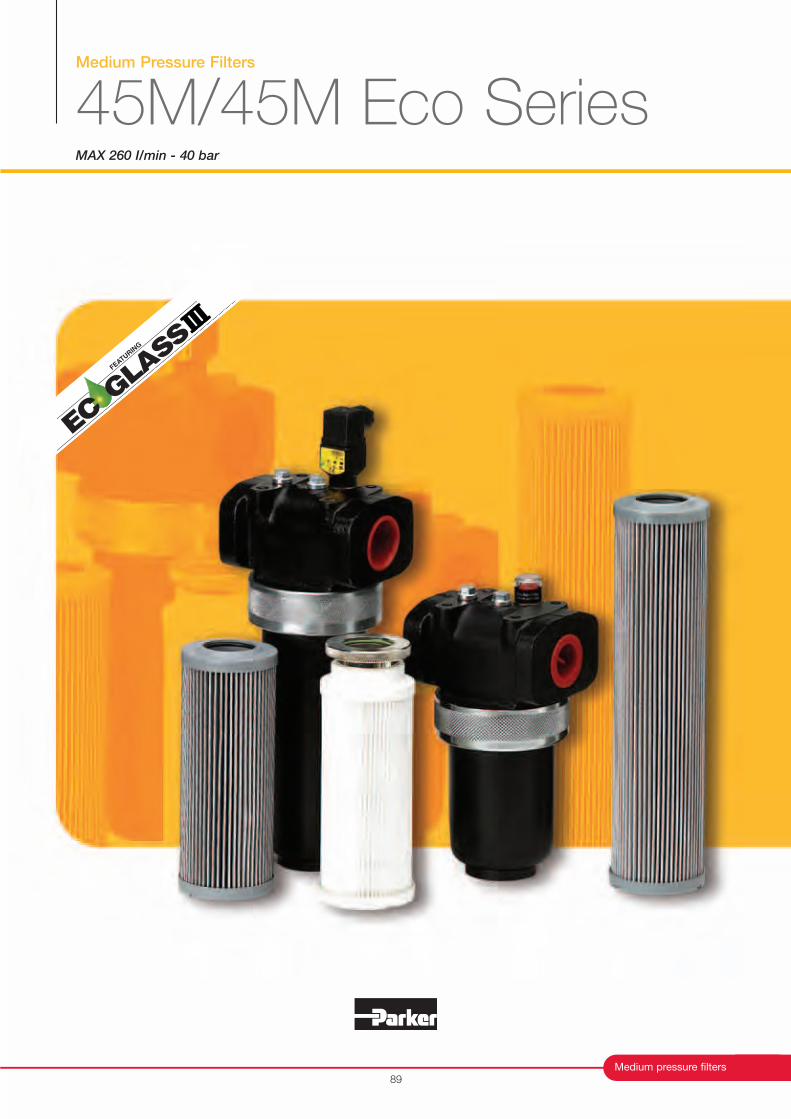
45M/45M Eco SeriesMAX 260 I/min - 40 bar
89
Medium pressure filters
FEATURIN
G
Medium Pressure Filters
45M/45M Eco Series
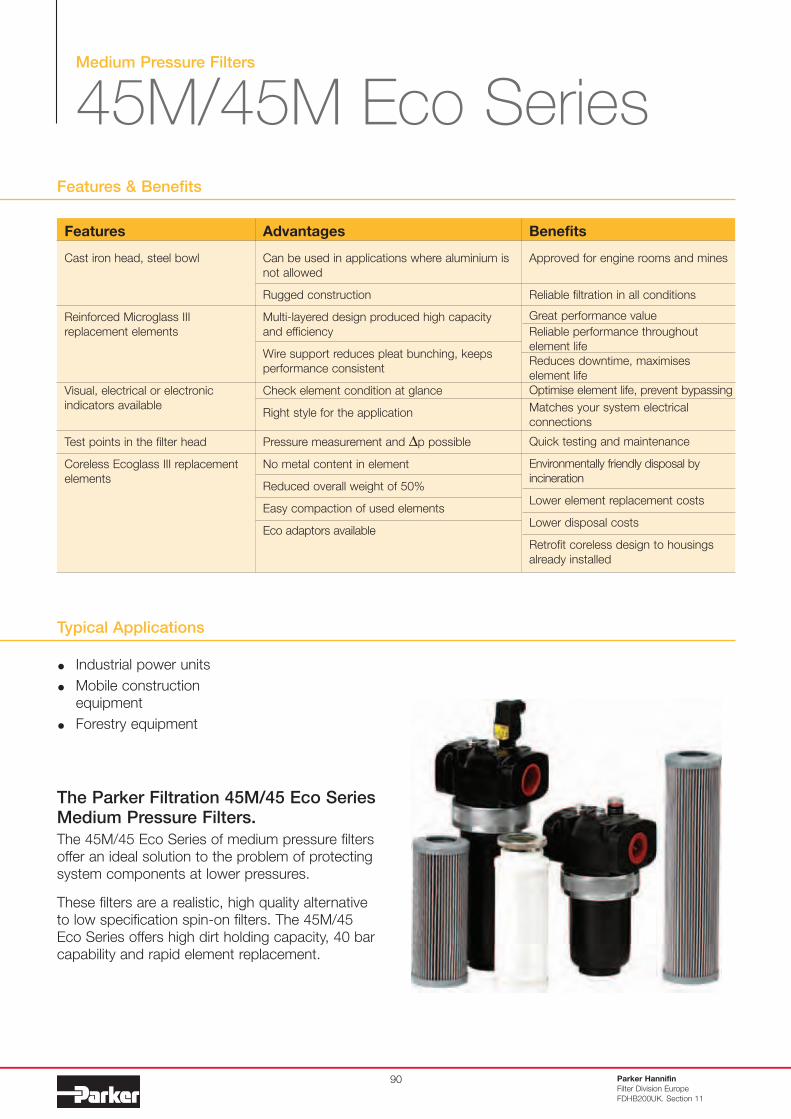
Typical Applications
Industrial power units
Mobile construction
equipment
Forestry equipment
The Parker Filtration 45M/45 Eco Series Medium Pressure Filters.
The 45M/45 Eco Series of medium pressure filters
offer an ideal solution to the problem of protecting
system components at lower pressures.
These filters are a realistic, high quality alternative
to low specification spin-on filters. The 45M/45
Eco Series offers high dirt holding capacity, 40 bar
capability and rapid element replacement.
Features & Benefits
Parker Hannifin
Filter Division Europe
FDHB200UK. Section 11
90
Features
Cast iron head, steel bowl
Reinforced Microglass III
replacement elements
Visual, electrical or electronic
indicators available
Test points in the filter head
Coreless Ecoglass III replacement
elements
Advantages
Can be used in applications where aluminium is
not allowed
Rugged construction
Multi-layered design produced high capacity
and efficiency
Wire support reduces pleat bunching, keeps
performance consistent
Check element condition at glance
Right style for the application
Pressure measurement and ∆p possible
No metal content in element
Reduced overall weight of 50%
Easy compaction of used elements
Eco adaptors available
Benefits
Approved for engine rooms and mines
Reliable filtration in all conditions
Great performance value
Reliable performance throughout
element life
Reduces downtime, maximises
element life
Optimise element life, prevent bypassing
Matches your system electrical
connections
Quick testing and maintenance
Environmentally friendly disposal by
incineration
Lower element replacement costs
Lower disposal costs
Retrofit coreless design to housings
already installed
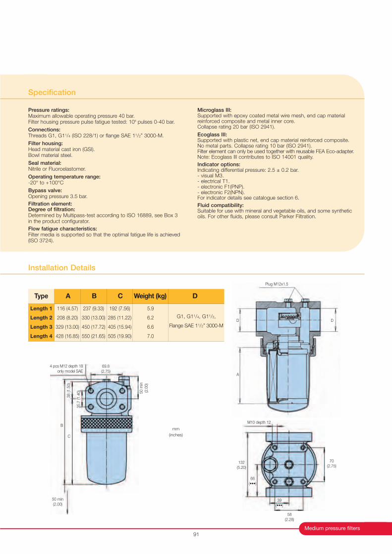
Type
116 (4.57)
208 (8.20)
329 (13.00)
428 (16.85)
237 (9.33)
330 (13.00)
450 (17.72)
550 (21.65)
192 (7.56)
285 (11.22)
405 (15.94)
505 (19.90)
G1, G11/4, G11/2,
Flange SAE 11/2” 3000-M
Length 1
Length 2
Length 3
Length 4
A B C Weight (kg) D
5.9
6.2
6.6
7.0
38 (1.5
0)
C
B
50 min
(2.00)
Plug M12x1.5
DD
A
70
(2.75)132
(5.20)
58
(2.28)
M10 depth 12
69.8
(2.75)
4 pcs M12 depth 18
only model SAE
35.7
(1.4
0)
mm
(inches)
Medium pressure filters
Installation Details
Specification
Pressure ratings:Maximum allowable operating pressure 40 bar.Filter housing pressure pulse fatigue tested: 106 pulses 0-40 bar.
Connections:Threads G1, G11/4 (ISO 228/1) or flange SAE 11/2” 3000-M.
Filter housing:Head material cast iron (GSI).Bowl material steel.
Seal material:Nitrile or Fluoroelastomer.
Operating temperature range:-20° to +100°C
Bypass valve:Opening pressure 3.5 bar.
Filtration element:Degree of filtration:Determined by Multipass-test according to ISO 16889, see Box 3 in the product configurator.
Flow fatigue characteristics:Filter media is supported so that the optimal fatigue life is achieved(ISO 3724).
Microglass III: Supported with epoxy coated metal wire mesh, end cap materialreinforced composite and metal inner core. Collapse rating 20 bar (ISO 2941).
Ecoglass III:Supported with plastic net, end cap material reinforced composite. No metal parts. Collapse rating 10 bar (ISO 2941).Filter element can only be used together with reusable FEA Eco-adapter.Note: Ecoglass III contributes to ISO 14001 quality.
Indicator options:Indicating differential pressure: 2.5 ± 0.2 bar.- visual M3.- electrical T1.- electronic F1(PNP).- electronic F2(NPN).For indicator details see catalogue section 6.
Fluid compatibility:Suitable for use with mineral and vegetable oils, and some syntheticoils. For other fluids, please consult Parker Filtration.
91
50 m
in
(2.0
0)
39
(•••)
66
(•••)
Medium Pressure Filters
45M/45M Eco Series
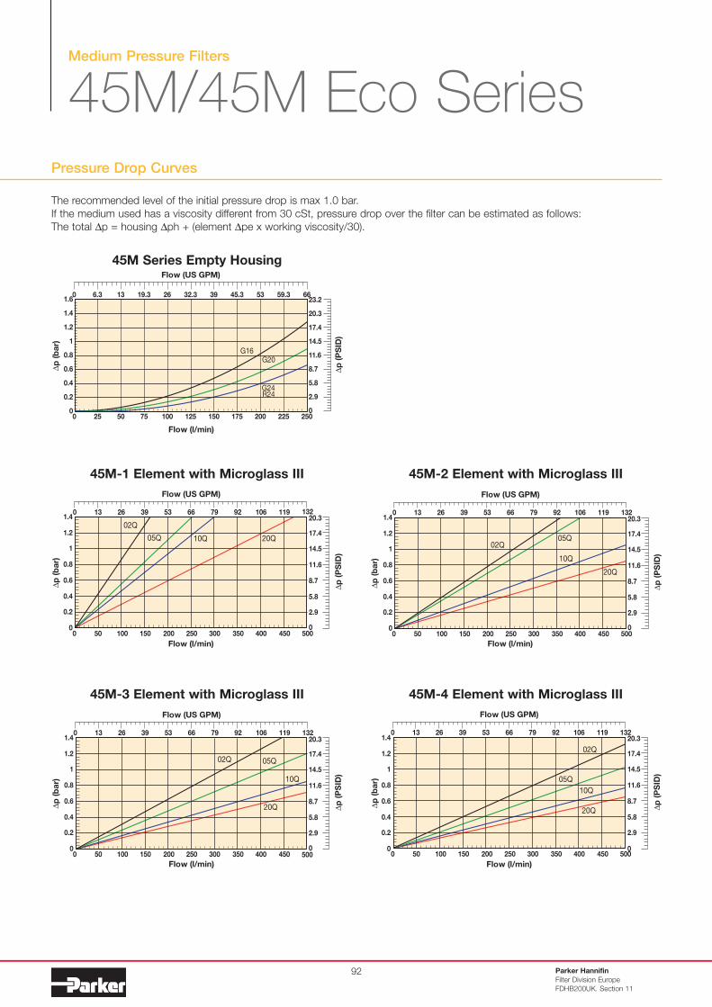
Pressure Drop Curves
The recommended level of the initial pressure drop is max 1.0 bar.
If the medium used has a viscosity different from 30 cSt, pressure drop over the filter can be estimated as follows:
The total ∆p = housing ∆ph + (element ∆pe x working viscosity/30).
Parker Hannifin
Filter Division Europe
FDHB200UK. Section 11
92
45M-1 Element with Microglass III
45M-3 Element with Microglass III
45M Series Empty Housing
45M-2 Element with Microglass III
45M-4 Element with Microglass III
0
0.2
0.4
0.6
0.8
1
1.2
1.4
0 50 100 150 200 250 300 350 400 450 500
Flow (l/min)
02Q
∆p
(b
ar)
05Q 10Q 20Q
∆p
(P
SID
)
0
2.9
5.8
8.7
11.6
14.5
17.4
20.3
Flow (US GPM)
0 13 26 39 53 66 79 92 106 119 132
0
0.2
0.4
0.6
0.8
1
1.2
1.4
0 50 100 150 200 250 300 350 400 450 500
Flow (l/min)
02Q
∆p
(b
ar)
05Q
10Q
20Q
∆p
(P
SID
)
0
2.9
5.8
8.7
11.6
14.5
17.4
20.3
Flow (US GPM)
0 13 26 39 53 66 79 92 106 119 132
0
0.2
0.4
0.6
0.8
1
1.2
1.4
0 50 100 150 200 250 300 350 400 450 500
Flow (l/min)
02Q
∆p
(b
ar)
05Q
10Q
20Q
∆p
(P
SID
)
0
2.9
5.8
8.7
11.6
14.5
17.4
20.3
Flow (US GPM)
0 13 26 39 53 66 79 92 106 119 132
0
0.2
0.4
0.6
0.8
1
1.2
1.4
1.6
0 25 50 75 100 125 150 175 200 225 250
G24R24
G20G16
23.2
20.3
14.5
2.9
0
8.7
∆p
(P
SID
)
Flow (l/min)
∆p
(b
ar)
0 6.3 32.3 53 66
Flow (US GPM)
13 19.3 26 39 45.3 59.3
5.8
11.6
17.4
0
0.2
0.4
0.6
0.8
1
1.2
1.4
0 50 100 150 200 250 300 350 400 450 500
Flow (l/min)
02Q
∆p
(b
ar) 05Q
10Q
20Q ∆p
(P
SID
)
Flow (US GPM)
0
2.9
5.8
8.7
11.6
14.5
17.4
20.30 13 26 39 53 66 79 92 106 119 132
Medium pressure filters
93
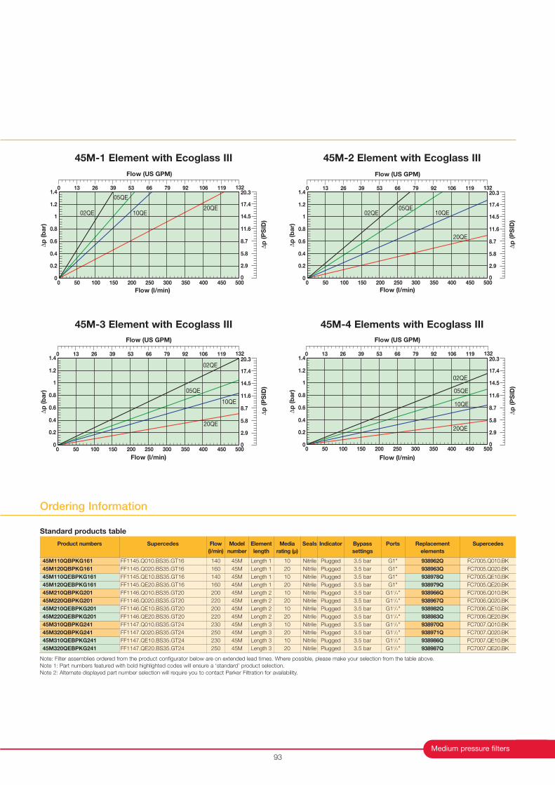
45M-1 Element with Ecoglass III
45M-3 Element with Ecoglass III 45M-4 Elements with Ecoglass III
45M-2 Element with Ecoglass III
0
0.2
0.4
0.6
0.8
1
1.2
1.4
0 50 100 150 200 250 300 350 400 450 500
Flow (l/min)
02QE
∆p
(b
ar)
05QE
10QE20QE
∆p
(P
SID
)
0
2.9
5.8
8.7
11.6
14.5
17.4
20.3
Flow (US GPM)
0 13 26 39 53 66 79 92 106 119 132
0
0.2
0.4
0.6
0.8
1
1.2
1.4
0 50 100 150 200 250 300 350 400 450 500
Flow (l/min)
02QE
∆p
(b
ar)
05QE10QE
20QE
∆p
(P
SID
)
0
2.9
5.8
8.7
11.6
14.5
17.4
20.3
Flow (US GPM)
0 13 26 39 53 66 79 92 106 119 132
0
0.2
0.4
0.6
0.8
1
1.2
1.4
0 50 100 150 200 250 300 350 400 450 500
Flow (l/min)
02QE
∆p
(b
ar) 05QE
10QE
20QE
∆p
(P
SID
)
0
2.9
5.8
8.7
11.6
14.5
17.4
20.3
Flow (US GPM)
0 13 26 39 53 66 79 92 106 119 132
0
0.2
0.4
0.6
0.8
1
1.2
1.4
0 50 100 150 200 250 300 350 400 450 500
Flow (l/min)
02QE
∆p
(b
ar) 05QE
10QE
20QE
∆p
(P
SID
)
0
2.9
5.8
8.7
11.6
14.5
17.4
20.3
Flow (US GPM)
0 13 26 39 53 66 79 92 106 119 132
Ordering Information
Note: Filter assemblies ordered from the product configurator below are on extended lead times. Where possible, please make your selection from the table above.
Note 1: Part numbers featured with bold highlighted codes will ensure a ‘standard’ product selection.
Note 2: Alternate displayed part number selection will require you to contact Parker Filtration for availability.
Product numbers
45M110QBPKG161
45M120QBPKG161
45M110QEBPKG161
45M120QEBPKG161
45M210QBPKG201
45M220QBPKG201
45M210QEBPKG201
45M220QEBPKG201
45M310QBPKG241
45M320QBPKG241
45M310QEBPKG241
45M320QEBPKG241
Supercedes
FF1145.Q010.BS35.GT16
FF1145.Q020.BS35.GT16
FF1145.QE10.BS35.GT16
FF1145.QE20.BS35.GT16
FF1146.Q010.BS35.GT20
FF1146.Q020.BS35.GT20
FF1146.QE10.BS35.GT20
FF1146.QE20.BS35.GT20
FF1147.Q010.BS35.GT24
FF1147.Q020.BS35.GT24
FF1147.QE10.BS35.GT24
FF1147.QE20.BS35.GT24
Flow
(l/min)
140
160
140
160
200
220
200
220
230
250
230
250
Model
number
45M
45M
45M
45M
45M
45M
45M
45M
45M
45M
45M
45M
Element
length
Length 1
Length 1
Length 1
Length 1
Length 2
Length 2
Length 2
Length 2
Length 3
Length 3
Length 3
Length 3
Media
rating (µ)
10
20
10
20
10
20
10
20
10
20
10
20
Seals
Nitrile
Nitrile
Nitrile
Nitrile
Nitrile
Nitrile
Nitrile
Nitrile
Nitrile
Nitrile
Nitrile
Nitrile
Indicator
Plugged
Plugged
Plugged
Plugged
Plugged
Plugged
Plugged
Plugged
Plugged
Plugged
Plugged
Plugged
Bypass
settings
3.5 bar
3.5 bar
3.5 bar
3.5 bar
3.5 bar
3.5 bar
3.5 bar
3.5 bar
3.5 bar
3.5 bar
3.5 bar
3.5 bar
Replacement
elements
938962Q
938963Q
938978Q
938979Q
938966Q
938967Q
938982Q
938983Q
938970Q
938971Q
938986Q
938987Q
Supercedes
FC7005.Q010.BK
FC7005.Q020.BK
FC7005.QE10.BK
FC7005.QE20.BK
FC7006.Q010.BK
FC7006.Q020.BK
FC7006.QE10.BK
FC7006.QE20.BK
FC7007.Q010.BK
FC7007.Q020.BK
FC7007.QE10.BK
FC7007.QE20.BK
Ports
G1"
G1"
G1"
G1"
G11/4"
G11/4"
G11/4"
G11/4"
G11/2"
G11/2"
G11/2"
G11/2"
Standard products table
Medium Pressure Filters
45M/45M Eco Series
Ordering Information (cont.)
Parker Hannifin
Filter Division Europe
FDHB200UK. Section 11
94
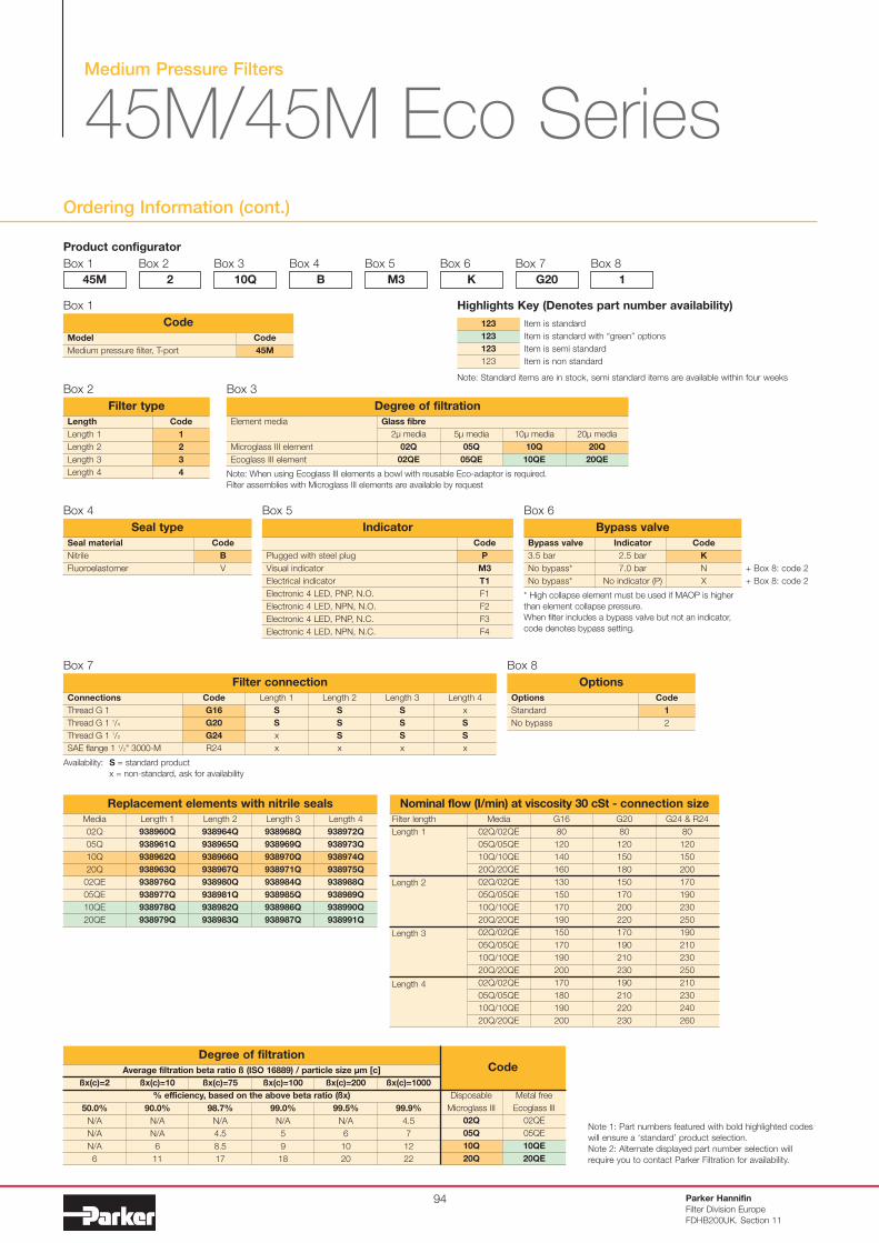
Product configurator
Box 1
Code
1
2
3
4
Length
Length 1
Length 2
Length 3
Length 4
Filter type
Box 2
45M
Box 2
2
Box 3
10Q
Box 4
B
Box 5
M3
Box 6
K
Box 7
G20
Box 8
1
Note 1: Part numbers featured with bold highlighted codes
will ensure a ‘standard’ product selection.
Note 2: Alternate displayed part number selection will
require you to contact Parker Filtration for availability.
Code
B
V
Seal material
Nitrile
Fluoroelastomer
Seal type
Box 4
Bypass valve
3.5 bar
No bypass*
No bypass*
Bypass valve
Indicator
2.5 bar
7.0 bar
No indicator (P)
Code
K
N
X
+ Box 8: code 2
+ Box 8: code 2
Box 6
Code
P
M3
T1
F1
F2
F3
F4
Plugged with steel plug
Visual indicator
Electrical indicator
Electronic 4 LED, PNP, N.O.
Electronic 4 LED, NPN, N.O.
Electronic 4 LED, PNP, N.C.
Electronic 4 LED, NPN, N.C.
Indicator
Box 5
Code
G16
G20
G24
R24
Connections
Thread G 1
Thread G 1 1/4
Thread G 1 1/2
SAE flange 1 1/2" 3000-M
Filter connection
Length 1
S
S
x
x
Length 2
S
S
S
x
Length 3
S
S
S
x
Length 4
x
S
S
x
Box 7
Code
1
2
Options
Standard
No bypass
Options
Box 8
Code
45M
Model
Medium pressure filter, T-port
Code
Box 1
* High collapse element must be used if MAOP is higher
than element collapse pressure.
When filter includes a bypass valve but not an indicator,
code denotes bypass setting.
Availability: S = standard product
x = non-standard, ask for availability
Media
02Q
05Q
10Q
20Q
02QE
05QE
10QE
20QE
Replacement elements with nitrile seals
Length 1
938960Q
938961Q
938962Q
938963Q
938976Q
938977Q
938978Q
938979Q
Length 2
938964Q
938965Q
938966Q
938967Q
938980Q
938981Q
938982Q
938983Q
Length 3
938968Q
938969Q
938970Q
938971Q
938984Q
938985Q
938986Q
938987Q
Length 4
938972Q
938973Q
938974Q
938975Q
938988Q
938989Q
938990Q
938991Q
Filter length
Length 1
Length 2
Length 3
Length 4
Nominal flow (I/min) at viscosity 30 cSt - connection size
Media
02Q/02QE
05Q/05QE
10Q/10QE
20Q/20QE
02Q/02QE
05Q/05QE
10Q/10QE
20Q/20QE
02Q/02QE
05Q/05QE
10Q/10QE
20Q/20QE
02Q/02QE
05Q/05QE
10Q/10QE
20Q/20QE
G16
80
120
140
160
130
150
170
190
150
170
190
200
170
180
190
200
G20
80
120
150
180
150
170
200
220
170
190
210
230
190
210
220
230
G24 & R24
80
120
150
200
170
190
230
250
190
210
230
250
210
230
240
260
Item is standard
Item is standard with “green” options
Item is semi standard
Item is non standard
123
123
123
123
Highlights Key (Denotes part number availability)
Note: Standard items are in stock, semi standard items are available within four weeks
Note: When using Ecoglass III elements a bowl with reusable Eco-adaptor is required.
Filter assemblies with Microglass III elements are available by request
Box 3
Element media
Microglass III element
Ecoglass III element
20µ media
20Q
20QE
10µ media
10Q
10QE
5µ media
05Q
05QE
2µ media
02Q
02QE
Glass fibre
Degree of filtration
Average filtration beta ratio ß (ISO 16889) / particle size µm [c]
% efficiency, based on the above beta ratio (ßx)
ßx(c)=2
50.0%
N/A
N/A
N/A
6
Degree of filtrationCode
ßx(c)=10
90.0%
N/A
N/A
6
11
ßx(c)=75
98.7%
N/A
4.5
8.5
17
ßx(c)=100
99.0%
N/A
5
9
18
ßx(c)=200
99.5%
N/A
6
10
20
ßx(c)=1000
99.9%
4.5
7
12
22
02Q
05Q
10Q
20Q
Disposable
Microglass III
02QE
05QE
10QE
20QE
Metal free
Ecoglass III
Medium Pressure Filters
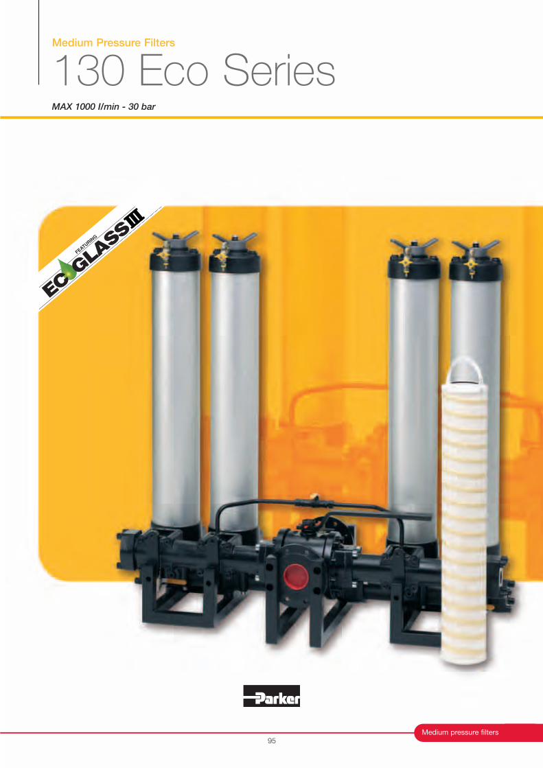
130 Eco SeriesMAX 1000 I/min - 30 bar
Medium pressure filters
FEATURIN
G
95
Medium Pressure Filters
130 Eco Series
96
Typical Applications
Paper production plants
Steel mills
Aluminium mills
Industrial power packs
Lubrication systems
Power generation
Features & Benefits
Parker Hannifin
Filter Division Europe
FDHB200UK. Section 12
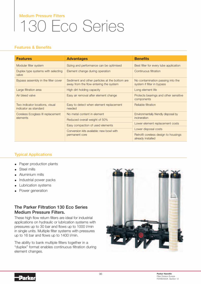
The Parker Filtration 130 Eco Series Medium Pressure Filters.
These high flow return filters are ideal for industrial
applications on hydraulic or lubrication systems with
pressures up to 30 bar and flows up to 1000 l/min
in single units. Multiple filter systems with pressures
up to 16 bar and flows up to 1400 l/min.
The ability to bank multiple filters together in a
“duplex” format enables continuous filtration during
element changes.
Features
Modular filter system
Duplex type systems with selecting
valve
Bypass assembly in the filter cover
Large filtration area
Air bleed valve
Two indicator locations, visual
indicator as standard
Coreless Ecoglass III replacement
elements
Advantages
Sizing and performance can be optimised
Element change during operation
Sediment and other particles at the bottom are
away from the flow entering the system
High dirt holding capacity
Easy air removal after element change
Easy to detect when element replacement
needed
No metal content in element
Reduced overall weight of 50%
Easy compaction of used elements
Conversion kits available: new bowl with
permanent core
Benefits
Best filter for every lube application
Continuous filtration
No contamination passing into the
system if filter in bypass
Long element life
Protects bearings and other sensitive
components
Reliable filtration
Environmentally friendly disposal by
incineration
Lower element replacement costs
Lower disposal costs
Retrofit coreless design to housings
already installed
Medium pressure filters
Installation Details
Specification
Pressure ratings:Maximum allowable operating pressure:Single filters 30 bar.Filter systems 16 bar.Filter housing pressure pulse fatigue tested: 106 pulses 0-25 bar.
Construction:Eco-element does not include any metal parts and is supported byEco-adaptor. Conventional elements can be used without removingthe Eco-adaptor.
Connections:Single unit connections:Flanges SAE 2” 3000-M, SAE 21/2” 3000-M or with adaptor threadsG11/2 or G2.
Dual unit connections:Flanges SAE 3” 3000-M or with adaptor threads G11/2 or G2.
Parallel unit and filter system assembly connections: DN80/PN16 or DN100/PN16. Assembly of two, four six or eight filters tothe same system by using L-bore valve assembly (only one side in use).
Filter housing:Material aluminium.
Seal material:Nitrile or Fluoroelastomer.
Operating temperature range:-20°C to +100°C.
Bypass valve:Opening pressure 3.5 bar.
Filter element:Degree of filtration:Determined by Multipass-test according to ISO 16889, see Box 3 in the product configurator.
Flow fatigue characteristics:Filter media is supported so that the optimal fatigue life is achieved (ISO3724).
Ecoglass III:Supported with plastic net, end cap material reinforced composite. Nometal parts. Collapse rating 10 bar (ISO 2941).Filter element can only be used together with reusable FEA Eco-adapter.Note: Ecoglass III contributes to ISO 14001 quality.Also available with Microglass III elements. Contact Parker Filtration fordetails.
Visual indicator:Includes M3, full part number FMUM3KVMU12H as standard.
Optional Indicators (mounted to lower indicator port):- electrical T1.- electronic F1(PNP).- electronic F2(NPN).For indicator details see catalogue section 6.
Fluid compatibility:Suitable for use with mineral and vegetable oils, and some syntheticoils. For other fluids, please consult Parker Filtration.
97
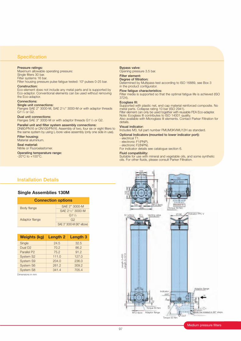
SAE 2” 3000-M
SAE 21/2” 3000-M
G11/2
G2
SAE 3” 3000-M (90° elbow)
Body flange
Adaptor flange
Connection options
24.5
70.2
75.2
111.0
204.0
261.2
341.4
32.5
86.2
91.2
127.0
236.0
309.2
705.4
Single
Dual D2
Parallel P2
System S2
System S9
System S6
System S8
Weights (kg) Length 2 Length 3
G1/2x2pcs G1/8 Venting valveIndicator FPC VØ196
Length
2=
650
Length
3=
1210
Indicator
port
A
Adaptor flange
128
Torque 50 Nm
Option.can be rotated in 90° steps.
In
OUT
1276
3
Torque 50 Nm
Adaptor flange
35
50.8
M12 4pcs
G1/2
42
88.9
102
50.8
100
200
M12 8pcs
96
126
35
222
10288.9
150
M12 4pcs
Torque 50 Nm
36
47
Direction A
Single Assemblies 130M
Dimensions in mm
Medium Pressure Filters
130 Eco Series
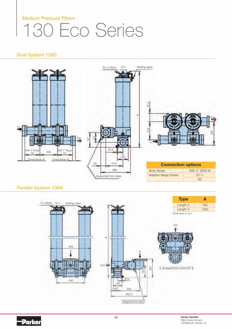
Dual System 130D
Parker Hannifin
Filter Division Europe
FDHB200UK. Section 12
98
In
Out
SAE 3” flange
191
SAE 3” flange
191
Thread flange 35 Thread flange 35
226
97.5
218
In
Out
282
635
440
In In
Out
Out
291
191
100
140
Ø14
345
562.5
Supported from base
G1/2x2pcs G1/8 Venting valve
A
Port Sizes DN80/PN16 or DN100/PN16
Parallel System 130N
Length 2
Length 3
780
1340
Type A
SAE 3” 3000-M
G11/2
G2
Body flange
Adaptor flange thread
Connection options
G1/2 x 2pcs G1/8 Venting valve
A
191
127
64 218
140
380
Ø14
Supported from base
Dimensions in mm
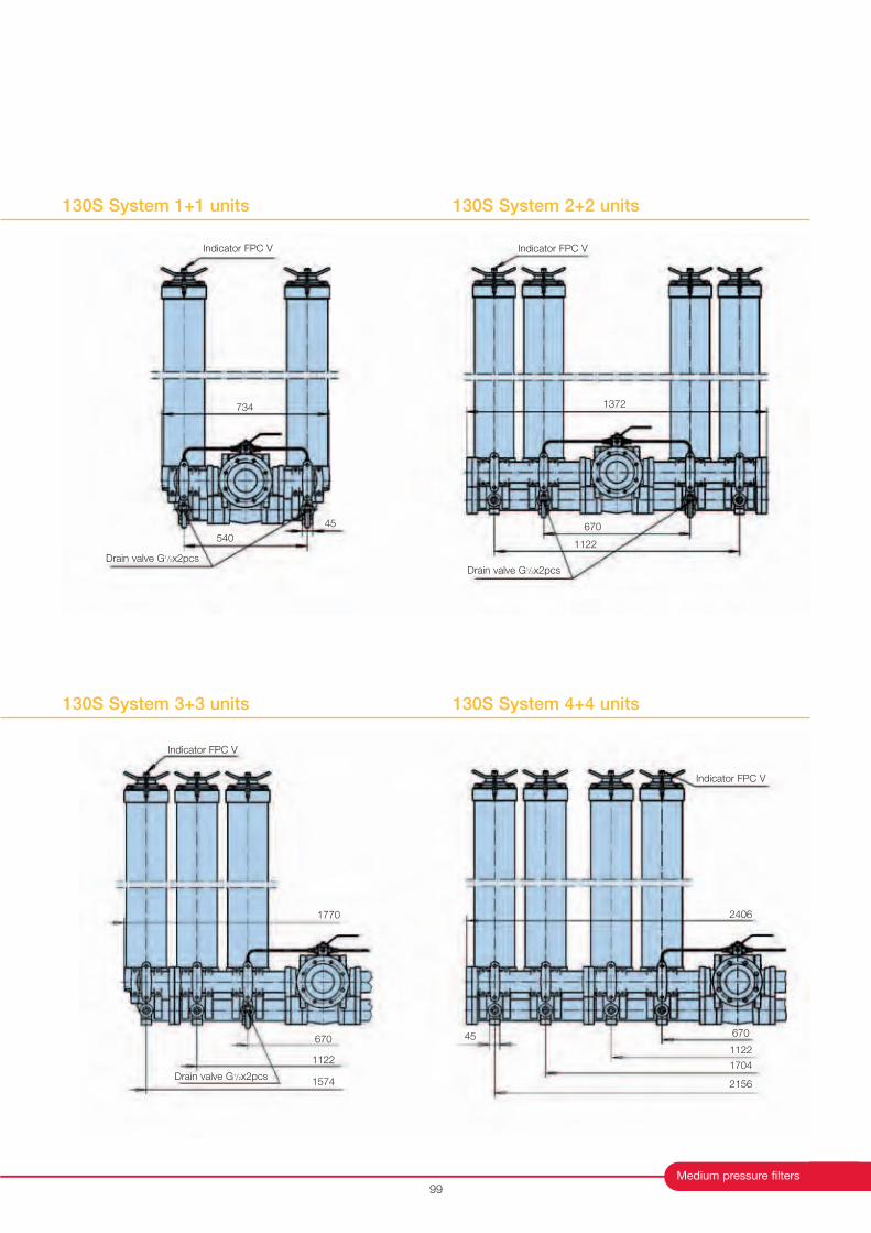
130S System 2+2 units
Medium pressure filters
130S System 1+1 units
99
Indicator FPC V
Drain valve G1/2x2pcs
540
45
734
Indicator FPC V
Drain valve G1/2x2pcs
1372
670
1122
Indicator FPC V
Drain valve G1/2x2pcs
1122
670
1574
1770
Indicator FPC V
2406
670
1122
1704
2156
45
130S System 3+3 units 130S System 4+4 units
Medium Pressure Filters
130 Eco Series
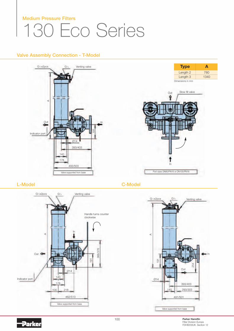
Valve Assembly Connection - T-Model
Parker Hannifin
Filter Division Europe
FDHB200UK. Section 12
100
G1/2x2pcs G1/8 Venting valve
191
InOut
A
140
178
493/503
393/403
Ø14
Indicator port
Valve supported from base Port sizes DN80/PN16 or DN100/PN16
In
Out Slow fill valve
Length 2
Length 3
780
1340
Type A
Valve supported from base
Valve supported from base
Indicator port
In
Out
A
G1/2x2pcs G1/8 Venting valve
191
366/3
76
140
178
Ø14
100 218
462/513
G1/2x2pcs G1/8 Venting valve
A
In
Out
191
Ø14
293/303
393/403
491/501
140
L-Model C-Model
Handle turns counter
clockwise
254
Dimensions in mm
Medium pressure filters
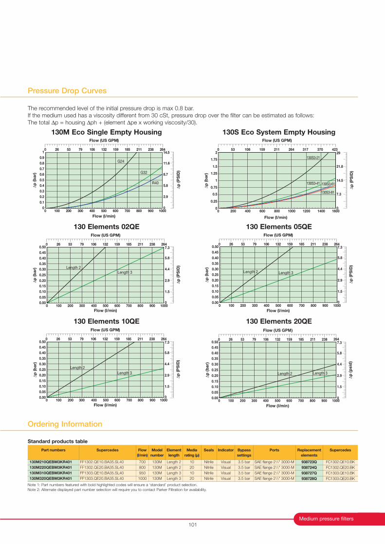
Pressure Drop Curves
101
The recommended level of the initial pressure drop is max 0.8 bar.
If the medium used has a viscosity different from 30 cSt, pressure drop over the filter can be estimated as follows:
The total ∆p = housing ∆ph + (element ∆pe x working viscosity/30).
G32
R40
G24
0
0.1
0.2
0.3
0.4
0.5
0.6
0.7
0.8
0.9
1
0 100 200 600 700 1000300 500 900
∆p
(b
ar)
Flow (l/min)
400 800
Flow (US GPM)
0 26 53 159 185 26479 132 238106 211
∆p
(P
SID
)
0
2.9
5.8
8.7
11.6
14.5
Flow (l/min)
∆p
(b
ar)
130S3-21
130S3-41
130S3-81
130S3-61
0 200 400 600 800 1000 1200 1400 16000
0.25
0.5
0.75
1
1.25
1.5
1.75
2
∆p
(P
SID
)
0
7.3
14.5
21.8
29
Flow (US GPM)
0 53 106 159 211 264 317 370 423
Flow (l/min)
Length 2Length 3
0 100 200 300 400 500 600 700 800 900 10000.00
0.05
0.10
0.15
0.20
0.25
0.30
0.35
0.40
0.45
0.50
∆p
(b
ar)
Flow (US GPM)
0 26 53 159 185 26479 132 238106 211
∆p
(P
SID
)
0
1.5
2.9
4.4
5.8
7.3
Length 2 Length 3
Flow (l/min)
0 100 200 300 400 500 600 700 800 900 10000.00
0.05
0.10
0.15
0.20
0.25
0.30
0.35
0.40
0.45
0.50
∆p
(b
ar)
Flow (US GPM)
0 26 53 159 185 26479 132 238106 211
∆p
(P
SID
)
0
1.5
2.9
4.4
5.8
7.3
∆p
(b
ar)
Flow (l/min)
Length 2
Length 3
0 100 200 300 400 500 600 700 800 900 10000.00
0.05
0.10
0.15
0.20
0.25
0.30
0.35
0.40
0.45
0.50
Flow (US GPM)
0 26 53 159 185 26479 132 238106 211
∆p
(P
SID
)
0
1.5
2.9
4.4
5.8
7.3
Flow (l/min)
Length 2 Length 3
0 100 200 300 400 500 600 700 800 900 10000.00
0.05
0.10
0.15
0.20
0.25
0.30
0.35
0.40
0.45
0.50
∆p
(b
ar)
Flow (US GPM)
0 26 53 159 185 26479 132 238106 211
∆p
(p
sid
)
0
1.5
2.9
4.4
5.8
7.3
130M Eco Single Empty Housing 130S Eco System Empty Housing
130 Elements 05QE
130 Elements 20QE
130 Elements 02QE
130 Elements 10QE
Ordering Information
Note 1: Part numbers featured with bold highlighted codes will ensure a ‘standard’ product selection.
Note 2: Alternate displayed part number selection will require you to contact Parker Filtration for availability.
Part numbers
130M210QEBM3KR401
130M220QEBM3KR401
130M310QEBM3KR401
130M320QEBM3KR401
Supercedes
FF1302.QE10.BA35.SL40
FF1302.QE20.BA35.SL40
FF1303.QE10.BA35.SL40
FF1303.QE20.BA35.SL40
Flow
(l/min)
700
800
950
1000
Model
number
130M
130M
130M
130M
Element
length
Length 2
Length 2
Length 3
Length 3
Media
rating (µ)
10
20
10
20
Seals
Nitrile
Nitrile
Nitrile
Nitrile
Indicator
Visual
Visual
Visual
Visual
Bypass
settings
3.5 bar
3.5 bar
3.5 bar
3.5 bar
Replacement
elements
938723Q
938724Q
938727Q
938728Q
Supercedes
FC1302.QE10.BK
FC1302.QE20.BK
FC1303.QE10.BK
FC1303.QE20.BK
Ports
SAE flange 21/2" 3000-M
SAE flange 21/2" 3000-M
SAE flange 21/2" 3000-M
SAE flange 21/2" 3000-M
Standard products table
Parker Hannifin
Filter Division Europe
FDHB200UK. Section 12
102
Medium Pressure Filters
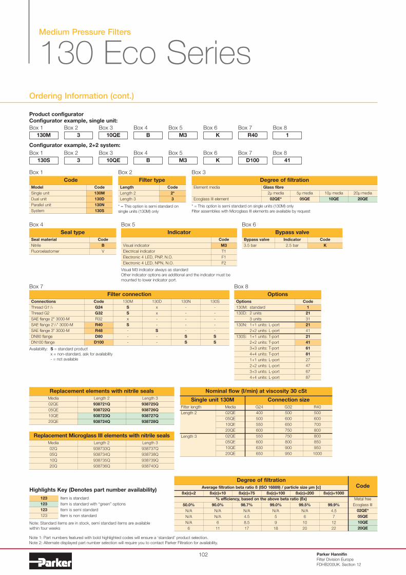
130 Eco Series
Ordering Information (cont.)
Product configurator
Configurator example, single unit:
Box 1
Code
2*
3
Length
Length 2
Length 3
Filter type
Box 2
130M
Box 2
3
Box 3
10QE
Box 4
B
Box 5
M3
Box 6
K
Box 7
R40
Box 8
1
Configurator example, 2+2 system:
Box 1
130S
Box 2
3
Box 3
10QE
Box 4
B
Box 5
M3
Box 6
K
Box 7
D100
Box 8
41
Note 1: Part numbers featured with bold highlighted codes will ensure a ‘standard’ product selection.
Note 2: Alternate displayed part number selection will require you to contact Parker Filtration for availability.
Code
B
V
Seal material
Nitrile
Fluoroelastomer
Seal type
Box 4
Bypass valve
3.5 bar
Bypass valve
Indicator
2.5 bar
Code
K
Box 6
Code
M3
T1
F1
F2
Visual indicator
Electrical indicator
Electronic 4 LED, PNP, N.O.
Electronic 4 LED, NPN, N.O.
Indicator
Box 5
Code
G24
G32
R32
R40
R48
D80
D100
Connections
Thread G11/2
Thread G2
SAE flange 2" 3000-M
SAE flange 21/2" 3000-M
SAE flange 3" 3000-M
DN80 flange
DN100 flange
Filter connection
130M
S
S
x
S
-
-
-
130D
x
x
-
-
S
-
-
130N
-
-
-
-
-
S
S
130S
-
-
-
-
-
S
S
Box 7
Code
1
21
31
21
41
21
41
61
81
27
47
67
87
Options
130M: standard
130D: 2 units
3 units
130N: 1+1 units: L-port
2+2 units: L-port
130S: 1+1 units: T-port
2+2 units: T-port
3+3 units: T-port
4+4 units: T-port
1+1 units: L-port
2+2 units: L-port
3+3 units: L-port
4+4 units: L-port
Options
Box 8
Code
130M
130D
130N
130S
Model
Single unit
Dual unit
Parallel unit
System
Code
Box 1
Availability: S = standard product
x = non-standard, ask for availability
- = not available
Media
02QE
05QE
10QE
20QE
Replacement elements with nitrile seals
Length 2
938721Q
938722Q
938723Q
938724Q
Length 3
938725Q
938726Q
938727Q
938728Q
Media
02Q
05Q
10Q
20Q
Replacement Microglass III elements with nitrile seals
Length 2
938733Q
938734Q
938735Q
938736Q
Length 3
938737Q
938738Q
938739Q
938740Q
Filter length
Length 2
Length 3
Connection sizeSingle unit 130M
Nominal flow (I/min) at viscosity 30 cSt
Media
02QE
05QE
10QE
20QE
02QE
05QE
10QE
20QE
G24
400
500
550
600
550
600
630
650
G32
500
600
650
750
750
800
900
950
R40
500
600
700
800
800
850
950
1000
* = This option is semi standard on
single units (130M) only
Visual M3 indicator always as standard
Other indicator options are additional and the indicator must be
mounted to lower indicator port.
Item is standard
Item is standard with “green” options
Item is semi standard
Item is non standard
123
123
123
123
Highlights Key (Denotes part number availability)
Note: Standard items are in stock, semi standard items are available
within four weeks
* = This option is semi standard on single units (130M) only
Filter assemblies with Microglass III elements are available by request
Box 3
Element media
Ecoglass III element
20µ media
20QE
10µ media
10QE
5µ media
05QE
2µ media
02QE*
Glass fibre
Degree of filtration
Average filtration beta ratio ß (ISO 16889) / particle size µm [c]
% efficiency, based on the above beta ratio (ßx)
ßx(c)=2
50.0%
N/A
N/A
N/A
6
Degree of filtrationCode
ßx(c)=10
90.0%
N/A
N/A
6
11
ßx(c)=75
98.7%
N/A
4.5
8.5
17
ßx(c)=100
99.0%
N/A
5
9
18
ßx(c)=200
99.5%
N/A
6
10
20
ßx(c)=1000
99.9%
4.5
7
12
22
02QE*
05QE
10QE
20QE
Metal free
Ecoglass III
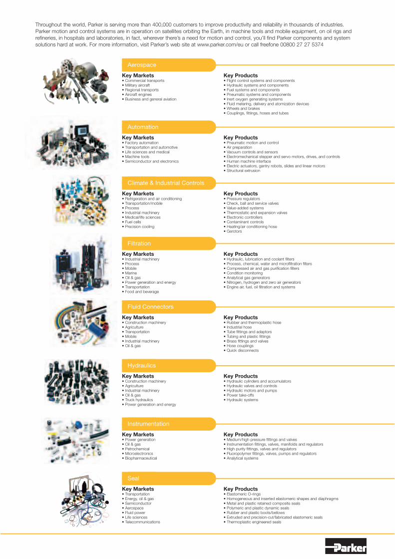
Throughout the world, Parker is serving more than 400,000 customers to improve productivity and reliability in thousands of industries.
Parker motion and control systems are in operation on satellites orbiting the Earth, in machine tools and mobile equipment, on oil rigs and
refineries, in hospitals and laboratories, in fact, wherever there’s a need for motion and control, you’ll find Parker components and system
solutions hard at work. For more information, visit Parker’s web site at www.parker.com/eu or call freefone 00800 27 27 5374
Key Markets• Commercial transports• Military aircraft• Regional transports• Aircraft engines• Business and general aviation
Key Products• Flight control systems and components• Hydraulic systems and components• Fuel systems and components• Pneumatic systems and components• Inert oxygen generating systems• Fluid metering, delivery and atomization devices• Wheels and brakes• Couplings, fittings, hoses and tubes
Aerospace
Key Markets• Factory automation• Transportation and automotive• Life sciences and medical• Machine tools• Semiconductor and electronics
Automation
Key Markets• Refrigeration and air conditioning• Transportation/mobile• Process• Industrial machinery• Medical/life sciences• Fuel cells• Precision cooling
Key Products• Pressure regulators• Check, ball and service valves• Value-added systems• Thermostatic and expansion valves• Electronic controllers• Contaminant controls• Heating/air conditioning hose• Gerotors
Climate & Industrial Controls
Key Markets• Industrial machinery• Process• Mobile• Marine• Oil & gas• Power generation and energy• Transportation• Food and beverage
Key Products• Hydraulic, lubrication and coolant filters• Process, chemical, water and microfiltration filters• Compressed air and gas purification filters• Condition monitoring• Analytical gas generators• Nitrogen, hydrogen and zero air generators• Engine air, fuel, oil filtration and systems
Filtration
Key Markets• Construction machinery• Agriculture• Transportation• Mobile• Industrial machinery• Oil & gas
Key Products• Rubber and thermoplastic hose• Industrial hose• Tube fittings and adaptors• Tubing and plastic fittings• Brass fittings and valves• Hose couplings• Quick disconnects
Fluid Connectors
Key Markets• Construction machinery• Agriculture• Industrial machinery• Oil & gas• Truck hydraulics• Power generation and energy
Key Products• Hydraulic cylinders and accumulators• Hydraulic valves and controls• Hydraulic motors and pumps• Power take-offs• Hydraulic systems
Hydraulics
Key Markets• Power generation• Oil & gas• Petrochemical• Microelectronics• Biopharmaceutical
Key Products• Medium/high pressure fittings and valves• Instrumentation fittings, valves, manifolds and regulators• High purity fittings, valves and regulators• Fluoropolymer fittings, valves, pumps and regulators• Analytical systems
Instrumentation
Key Markets• Transportation• Energy, oil & gas• Semiconductor• Aerospace• Fluid power• Life sciences• Telecommunications
Key Products• Elastomeric O-rings • Homogeneous and inserted elastomeric shapes and diaphragms• Metal and plastic retained composite seals• Polymeric and plastic dynamic seals• Rubber and plastic boots/bellows• Extruded and precision-cut/fabricated elastomeric seals• Thermoplastic engineered seals
Seal
Key Products• Pneumatic motion and control• Air preparation• Vacuum controls and sensors• Electromechanical stepper and servo motors, drives, and controls• Human machine interface• Electric actuators, gantry robots, slides and linear motors• Structural extrusion
The Ch ice is
Perfectly Clear
Parker Sales UK
Worldwide Sales
Locations
Tachbrook Park Drive
Tachbrook Park, Warwick
CV34 6TU, UK
Tel: +44 (0) 1926 317 878
Fax: +44 (0) 1926 317 855
Email: [email protected]
For international sales enquiries
contact the appropriate worldwide
sales location.
Argentina +54 (11) 4752 4129
Australia +61 (2) 9 634 777
Austria +43 2622 23501-0
Belgium +32 (67) 280900
Brazil +55 12 3955 1000
Canada +1 800 272 7537
Central & South
America/Caribbean +1 305 470 8800
China +86 (21) 6445 9339
Czech Republic +42 (0) 2 830 85 221
Denmark +45 (0) 43 56 04 00
Finland +358 20 7532 500
France +33 4 50 25 80 25
Germany +49 (0) 2131 40160
Hong Kong +852 (2) 428 8008
Hungary +36 (1) 252 8137
India +91 55907081 85
Indonesia +60 3 5638 1476
Italy +39 02 451921
Japan +81 3 6408 3900
Jordan +962 (6) 810679
Korea +82 31 379 2200
Malaysia +62 811 179135
Mexico +1 800 272 7537
Netherlands +31 (0) 541 585000
New Zealand +64 (9) 573 1523
Norway +47 64 91 1000
Philippines +63 34 4323 779
Poland +48 2257 32400
Russia +7 (495) 580-9145
Singapore +65 688 76300
South Africa +27 (11) 961 0700
Spain +34 (91) 675 7300
Sweden +46 8 5979 5000
Switzerland +41 31 917 1850
Taiwan +886 (2) 2298 8987
Thailand +662 693 3304
United Arab Emirates +971 2 6788587
United Kingdom +44 (0) 1926 317878
USA +1 800 272 7537
Venezuela +58 212 238 54 22
www.parker.com/eurofilt Email:[email protected]
For all other countries please contact: European Product
Information Centre (24 Hr.): 00800 27 27 5374
(AU, BE, CH, DE, EI, FR and UK only)
All other countries:
+44 (0)1442 358 429 (English)
+44 (0)1442 358 428 (Deutsch)
+44 (0)1442 358 427 (Français)
Distributor
©Parker Hannifin 2006 Brochure: Ref: FDHB200UK Issue Date: 06/06