hydraulic excavator pc800-8/lc-8 - komatsu · 2 walk-around the komatsu dash 8 crawler excavators...
TRANSCRIPT

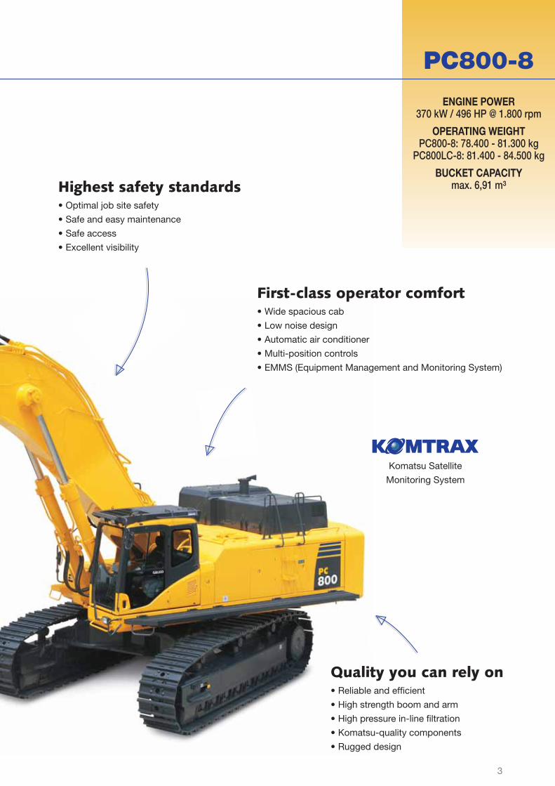
PC800-8/LC-8
ENGINE POWER370 kW / 496 HP @ 1.800 rpm
OPERATING WEIGHTPC800-8: 78.400 - 81.300 kg
PC800LC-8: 81.400 - 84.500 kg
BUCKET CAPACITYmax. 6,91 m³
Hydraulic Excavator
PC800

2
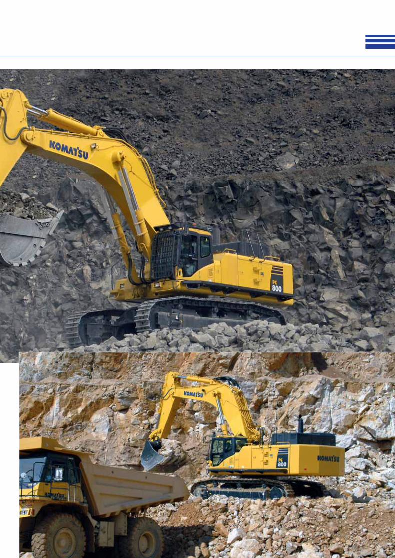
Walk-AroundThe Komatsu Dash 8 crawler excavators set new worldwide standards for quarry & mining
equipment. Operator safety and comfort is a focal point in their design, and their outstanding
performance and specifi cations will contribute directly to the success of your business. These
powerful and robust machines are designed to stand up to the hardest working conditions
while still maintaining maximum productivity. Safely rely on Komatsu’s 80 years of experience
and commitment to quality and durability: your Dash 8 crawler excavator will quickly become
your number one business partner.
Powerful and environmentally friendly• Low consumption ecot3 engine
• Hydraulic drive radiator cooling fan
• Less ambient noise
• Exceptional drawbar pull
and steering force
• Selectable working modes
Maximum productivity• Powerful digging force
• High speed work equipment
• Heavy lift mode
• Shockless boom control
• Swing priority mode
3
PC800-8
Komatsu Satellite
Monitoring System
First-class operator comfort• Wide spacious cab
• Low noise design
• Automatic air conditioner
• Multi-position controls
• EMMS (Equipment Management and Monitoring System)
Highest safety standards• Optimal job site safety
• Safe and easy maintenance
• Safe access
• Excellent visibility
Quality you can rely on• Reliable and effi cient
• High strength boom and arm
• High pressure in-line fi ltration
• Komatsu-quality components
• Rugged design
ENGINE POWER370 kW / 496 HP @ 1.800 rpm
OPERATING WEIGHTPC800-8: 78.400 - 81.300 kg
PC800LC-8: 81.400 - 84.500 kg
BUCKET CAPACITYmax. 6,91 m³

4
Maximum Productivity
Two-mode boom control
Smooth mode
Boom fl oats upward, reducing lifting of ma-
chine front. This facilitates gathering blasted
rock and scraping down operations.
Power mode
Boom pushing force is increased, ditch
digging and box digging operation on hard
ground are improved.
Shockless boom control
The PC800-8 features a shockless
valve (double-check slow return
valve) that automatically reduces
the vibration level when operat-
ing the boom. Operator fatigue is
reduced - which can improve safety
and productivity- and spillage
caused by vibrations is minimised.
High work equipment speed
A quick return circuit reduces the
time needed to unload the bucket.
During the arm dump operation, a
portion of oil fl ow is returned direct-
ly to the hydraulic tank. Combined
with the increased bucket dump
speed, loading work can be carried
out more quickly and effi ciently.
Powerful digging force
Thanks to the high engine out-
put and an optimised hydraulic
system, the PC800-8 delivers a
powerful bucket digging force of
up to 431 kN (43,9 tonnes) and an
arm crowd force of up to 341 kN
(34,8 tonnes).
Heavy lift mode
When handling rock or for heavy
lifting applications, the operator
can select the “heavy lift” mode to
gain 10% more lifting force on the
boom.
Swing priority mode
A twin swing motor system pro-
vides excellent swing performance,
with high speed and strong braking
power. The swing priority setting
allows using the same smooth mo-
tion for either 180° or 90° loading
operations. By altering the oil fl ow,
the operator selects either boom or
swing as the priority for increased
production.

5

6
Powerful and Environmentally Friendly
Komatsu SAA6D140E-5
Low consumption ecot3 engine
Designed and manufactured by
Komatsu, the SAA6D140E-5 engine
provides high torque, a better
performance at low speed, and low
fuel consumption. With direct fuel
injection, turbocharger, common
rail air-to-air aftercooler and cooled
EGR system, productivity and fuel
effi ciency are maximized.
Meets EU Stage IIIA
The Komatsu ecot3 engine technol-
ogy reduces NOx and particle emis-
sions, fuel consumption and noise
level. The Komatsu SAA6D140E-5
engine is certifi ed for EPA Tier III
and EU Stage IIIA emission regula-
tions.
Variable speed fan
4-stage Economy mode
Exceptional drawbar pull and steering force
Regardless of the selected travel
speed, the fi nal drives automatically
compensate for the load and give
maximum driving force whenever
needed. As a result, the PC800-8
generates exceptional drawbar pull
and steering force, giving smooth,
confi dent and safe machine move-
ment.
Less ambient noise
The PC800-8 is an exceptionally
powerful machine that maintains
low operating noise levels. In addi-
tion to the electronically-controlled
variable-speed fan drive, external
noise levels are further reduced to
meet EU Stage 2 noise regulations
by a low-noise glass wool furnished
muffl er with cover, a hybrid fan, and
low-noise components.
Hydraulic drive radiator cooling fan
The engine cooling fan rotation
speed is electronically controlled
and depends on the engine coolant
and the hydraulic oil temperatures:
the higher the temperature, the
faster the fan will turn. This system
increases fuel effi ciency, reduces
the operating noise levels and
requires less horsepower than belt
driven fans.

7
Selectable working modes
The selectable “Power” or “Econo-
my” modes are designed to match
the engine speed, pump speed and
system pressure to the current ap-
plication. They give the operator the
fl exibility to match the equipment
performance to the job at hand.
The Economy mode has 4 stages,
for an optimum combination of
economy and production.

8
First-Class Operator ComfortWide spacious cab
The wide and spacious cab in-
cludes a heated air suspension
seat with a reclining backrest. The
seat height and longitudinal incli-
nation are easily adjusted with a
pull-up lever. You can also set the
operational posture of the armrest
and the position of the console
or recline the seat all the way to
place it into a fully fl at state with the
headrest attached.
Automatic air conditioner
An automatic air conditioner, an air
fi lter and a positive internal air pres-
sure (60 Pa) combine to prevent
external dust from entering the cab.
Cab damper mounting
The built-in stability of the Komatsu
PC800-8, combined with a highly
rigid deck and a sprung multi-layer
viscous mount system, drastically
reduces vibration levels for the
operator.
Multi-position controls
The operator can work precisely
and in complete control and
comfort thanks to the multi-posi-
tion, proportional pressure control
levers. A double-slide mechanism
lets the seat and controllers move
together or independently, to be
positioned for maximum productiv-
ity and comfort.
Low noise design
Reduced fan speed, a large capac-
ity radiator, and the optimal usage
of sound insulation and of sound
absorbing materials help to make
the inside of your Dash 8 excava-
tor one of the quietest places in the
quarry.
Automatic air conditioner
Storage compartment
3 button lever

9
EMMS (Equipment Manage-ment and Monitoring System)
The EMMS is a highly sophisticated
system that controls and monitors
all the excavator functions. The
user interface is very intuitive and
provides the operator with easy
access to a huge range of functions
and operating information. The
high-resolution screen is easy to
read even in bright sunlight.

10
Highest Safety StandardsOptimal job site safety
Safety features on the Komatsu
PC800-8 comply with the latest
industry standards and work
together as a system to minimise
risks to personnel in and around the
machine. An audible travel alarm
further promotes job site safety.
Step light with timer
Wide walkway Anti-slip plates
Safe access
A wide catwalk and large handrails
give safe and easy access to the
cab and to maintenance check
points. Slip-resistant serrated
plates on working surfaces provide
improved foot traction.
Excellent visibility
The PC800-8’s large capacity cab
and increased glass area provide
superb front visibility. Large mirrors
on both sides ensure that ma-
chine visibility meets the latest ISO
standards. Additional work lamps
and a rotating beacon are fi tted as
standard, further enhancing safety.
Safe and easy maintenance
Thermal guards are placed around
high temperature parts of the
engine. The fan belt and pulleys
are well protected and in case of
damage, fi re risk is reduced by a
pump/engine partition that prevents
hydraulic oil from spraying onto the
engine.

11

12
Quality You Can Rely On
Komatsu bucket with Kmax teeth Full length track roller guards (optional)
Komatsu-quality components
With the latest computer design
techniques and a thorough test pro-
gramme, Komatsu’s global know-
how produces machines that are
designed, manufactured and tested
to meet your highest standards.
Rugged design
Komatsu strives to minimise the
welding areas on every machine
- particularly in highly loaded areas.
The swing circle mounting on the
upper structure of the machine and
the undercarriage tower to which
the swing circle is attached are
made from one piece of solid steel,
with no welding. The undercarriage
is strengthened to provide excel-
lent reliability and durability when
working on rocky ground or blasted
rock. Sturdy guards shield the
travel motors and piping against
damage from rocks.
Reliable and effi cient
Productivity is the key to success
– all major components of the
PC800-8 are designed and manu-
factured by Komatsu. All essential
functions are perfectly matched
for a highly reliable and productive
machine.
High strength boom and arm
Thanks to the large cross-sectional
structure made with high tensile
strength steel and a thick plate
and partition wall, the boom and
arm provide excellent durability
and are highly resistant to bending
and twisting. Highly durable rub-
bing strips on the underside of the
arm protect the structure from any
material that might fall from the
bucket.
High pressure in-line fi ltration
The PC800-8 has the most ex-
tensive fi ltration system available,
providing in-line fi lters as standard
equipment. An in-line fi lter in the
outlet port of each main hydraulic
pump reduces failure caused by
contamination.
Sturdy travel motor guards
13

14
Komatsu Satellite Monitoring System
KOMTRAX™ is a revolutionary
machine tracking system designed
to save you time and money. You
can now monitor your equipment
anytime and anywhere. Use valu-
able machine data received via the
KOMTRAX™ web site to optimise
your maintenance planning and
machine performances.
KOMTRAX™ can assist you with:
Full machine monitoring
Get detailed operation data to know
when your machines are used and
how productive they are.
Total Fleet Management
Keep track of the location of your
machines at all times and discour-
age unapproved usage or theft.
Complete machine status
Receive warnings, alerts and cau-
tions, via a web site or by e-mail,
to help with maintenance planning
and for longer machine life.
For further details on KOMTRAX™,
please ask your Komatsu dealer for
the latest KOMTRAX™ brochure.

15
KOMTRAX™
Alarm notifi cations - You can receive notifi -
cation of alarms both via the KOMTRAX™
website and by e-mail.
Added security - The “engine lock” feature
allows to program when a machine’s engine
can be started. And with “geo-fence”,
KOMTRAX™ sends notifi cation every time
your machine moves in or out of a predeter-
mined operating area.
Fleet location - The machine list instantly
locates all your machines, even those in
other countries.
Maintenance planning - To increase produc-
tivity and improve maintenance planning,
alerts indicate when items such as fi lters or
oil must be replaced.
Machine tracking during transport - When
your machine is transported, KOMTRAX™
sends travel messages to the web site or
by e-mail to inform you of its progress, and
confi rms when it reaches its destination.
Machine working time - With the “daily work-
ing record” chart, get precise engine running
time data: when your machine was started
and when it was shut down, as well as total
engine running time.

16
Easy Maintenance
Long-life oil fi lters
The hydraulic oil
fi lter uses high
performance
fi ltering material
for long element
replacement
intervals, which
signifi cantly
reduces mainte-
nance costs.
Flexible warranty
When you purchase Komatsu
equipment, you gain access to a
broad range of programmes and
services that have been designed
to help you get the most from
your investment. For example,
Komatsu’s Flexible Warranty
Programme provides a range of
extended warranty options on
the machine and its components.
These can be chosen to meet your
individual needs and activities. This
programme is designed to help
reduce total operating costs.
Centralized service
Check points are concentrated on
one side of the engine to facilitate
daily servicing.
Increased fuel tank capacity
The fuel tank capacity was in-
creased from 880 ltr to 980 ltr to
extend operating hours before
refuelling.
Steps connected to the machine cab
For easy engine and maintenance,
steps allow access from the left
hand catwalk to the top of the
machine.
Motorised grease gun equipped with hose reel
Greasing is made easy with the
electric motorised grease gun and
indicator.
Easier radiator cleaning
Reverse rotation function of fan al-
lows easier
cleaning of
the radiator.
5-step dust indicator
Informs of air cleaner
clogging in 5 steps
to warn of fi lter
condition.

17
Fuel tank...................................................................................980 ltr
Radiator....................................................................................100 ltr
Engine oil ....................................................................................53 ltr
Swing drive........................................................................2 × 24,5 ltr
Hydraulic tank ..........................................................................470 ltr
Final drive (each side).................................................................20 ltr
PTO case......................................................................................6 ltr
SERVICE REFILL CAPACITIES
UNDERCARRIAGE
Construction................... H-leg frame with box section track-frames
Track assembly
Type .............................................................................Fully sealed
Shoes (each side) ........................................... 47 (PC800LC-8: 51)
Tension.............................................................................Hydraulic
Rollers
Track rollers (each side) ...................................... 8 (PC800LC-8: 9)
Carrier rollers (each side) ..............................................................3
DRIVES AND BRAKES
Steering control .................................................. 2 levers with pedals
Drive method............................................................Fully hydrostatic
Travel motor................................. Axial piston motor, in-shoe design
Reduction system....................................Planetary double reduction
Max. drawbar pull...............................................................57.000 kg
Gradeability ................................................................................ 70%
Max. travel speeds
Lo / Hi .......................................................................2,8 / 4,2 km/h
Service brake...............................................................Hydraulic lock
Parking brake ...............................................................Oil disc brake
SWING SYSTEM
Type .......................................................................... Hydraulic motor
Swing reduction ..........................................................Planetary gear
Swing circle lubrication ..............................................Grease-bathed
Swing lock....................................................................Oil disc brake
Swing speed.......................................................................... 6,8 rpm
ENVIRONMENT
Engine emissions ...................Fully complies with EU Stage IIIA and
EPA Tier III exhaust emission regulations
Noise levels
LwA external ................................108 dB(A) (2000/14/EC Stage 2)
LpA operator ear........................73 dB(A) (ISO 6396 dynamic test)
Vibration levels (EN 12096:1997)*
Hand/arm............................≤ 2,5 m/s² (uncertainty K = 0,20 m/s²)
Body ...................................≤ 0,5 m/s² (uncertainty K = 0,04 m/s²)
* for the purpose of risk assessment under directive 2002/44/EC,
please refer to ISO/TR 25398:2006.
HYDRAULIC SYSTEM
Type ............................................. Open-center load-sensing system
Additional circuits...........Additional hydraulic function (preparation),
double acting only
Number of selectable working modes .............................................2
Main pump ........................................ Variable capacity piston pump
Pumps for.................. Boom, arm, bucket, swing, and travel circuits
Maximum pump fl ow.................................................. 2 × 494 ltr/min
Fan drive pump ................................. Variable capacity piston pump
Hydraulic motors:
Travel............................. 2 × axial piston motor with parking brake
Swing ..................2 × axial piston motor with swing holding brake
Relief valve settings
Implement circuits ..............................................................320 bar
Travel circuit........................................................................350 bar
Swing circuit .......................................................................290 bar
Heavy lift circuit ..................................................................350 bar
Pilot circuit ............................................................................30 bar
ENGINE
Model .......................................................... Komatsu SAA6D140E-5
Type ...............................Common rail direct injection, water-cooled,
cooled EGR, turbocharged, after-cooled diesel
Engine power
at rated engine speed.................................................... 1.800 rpm
ISO 14396............................................................370 kW / 496 HP
ISO 9249 (net engine power) ...............................363 kW / 487 HP
No. of cylinders ................................................................................6
Bore × stroke...............................................................140 × 165 mm
Displacement.........................................................................15,24 ltr
Fan drive type......................................................................Hydraulic
Specifi cations
Operating weight, including boom, arm, bucket, operator, lubricant, coolant, full fuel tank and the standard equipment.
OPERATING WEIGHT (APPR.)
PC800-8 PC800LC-8
Work equipment7,1 m boom / 2,9 m arm /
4,0 m³ bucket (SAE)8,0 m boom / 3,6 m arm /
3,4 m³ bucket (SAE)7,1 m boom / 2,9 m arm /
4,0 m³ bucket (SAE)8,0 m boom / 3,6 m arm /
3,4 m³ bucket (SAE)
Wide double grouser shoesOperating
weightGround pressure
Operating weight
Ground pressure
Operating weight
Ground pressure
Operating weight
Ground pressure
610 mm 78.400 kg 1,30 kg/m² 79.400 kg 1,31 kg/m² - - - -
710 mm 79.200 kg 1,12 kg/m² 80.200 kg 1,14 kg/m² - - - -
810 mm 79.800 kg 0,99 kg/m² 80.700 kg 1,00 kg/m² 81.400 kg 0,92 kg/m² 82.300 kg 0,93 kg/cm²
910 mm 80.400 kg 0,89 kg/m² 81.300 kg 0,90 kg/m² - - - -
1.010 mm - - - - 82.900 kg 0,75 kg/m² 83.800 kg 0,76 kg/cm²
1.110 mm - - - - 83.600 kg 0,69 kg/m² 84.500 kg 0,69 kg/cm²

18
Dimensions & Performance Figures
MODEL PC800LC-8 PC800-8
Boom length 8.040 mm 7.100 mm 8.040 mm 7.100 mm
Arm length 3.600 mm 2.945 mm 3.600 mm 2.945 mm
A Overall length 13.995 mm 13.130 mm 13.995 mm 13.130 mm
B Overall width (incl. catwalk) 4.335 mm 4.335 mm 4.335 mm 4.335 mm
C Overall height (to top of boom) 4.850 mm 4.615 mm 4.850 mm 4.615 mm
D Overall height (to top of Komtrax antenna) 3.720 mm 3.720 mm 3.720 mm 3.720 mm
E Clearance under counterweight 1.560 mm 1.560 mm 1.560 mm 1.560 mm
F Minimum ground clearance 840 mm 840 mm 840 mm 840 mm
G Tail swing radius 4.400 mm 4.400 mm 4.400 mm 4.400 mm
H Tumbler centre distance 5.020 mm 5.020 mm 4.500 mm 4.500 mm
I Track length 6.327 mm 6.327 mm 5.810 mm 5.810 mm
J Track gauge (working position) 3.500 mm 3.500 mm 3.500 mm 3.500 mm
K Width of crawler 4.210 mm 4.210 mm 4.110 mm 4.110 mm
Width of crawler (when retracted) 3.490 mm 3.490 mm 3.390 mm 3.390 mm
L Track shoe width 710 mm 710 mm 610 mm 610 mm
M Grouser height 50 mm 50 mm 50 mm 50 mm
N Machine height (to top of engine cover) 3.665 mm 3.665 mm 3.665 mm 3.665 mm
O Machine height (to top of exhaust pipe) 4.400 mm 4.400 mm 4.400 mm 4.400 mm
P Machine cab width 3.265 mm 3.265 mm 3.265 mm 3.265 mm
Q Distance, swing center to rear end 4.345 mm 4.345 mm 4.345 mm 4.345 mm
Max. capacity and weight have been calculated according to ISO 10567:2007.
Please consult with your distributor for the correct selection of buckets and attachments to suit the application.
A
I
H
G/Q
B
P
J
K
F
D
E
C
M
N O
L
MAX. BUCKET CAPACITY AND WEIGHT
PC800-8 PC800LC-8
Arm length2,9 m
(7,1 m boom)
3,6 m
(8,2 m boom)
2,9 m
(7,1 m boom)
3,6 m
(8,2 m boom)
Material weight up to 1,2 t/m³ 6,55 m³ 4.225 kg 5,31 m³ 3.950 kg 6,91 m³ 4.300 kg 5,60 m³ 4.025 kg
Material weight up to 1,5 t/m³ 5,40 m³ 3.975 kg 4,38 m³ 3.750 kg 5,70 m³ 4.025 kg 4,61 m³ 3.800 kg
Material weight up to 1,8 t/m³ 4,60 m³ 3.800 kg 3,73 m³ 3.625 kg 4,85 m³ 3.850 kg 3,93 m³ 3.650 kg

19
UPPER STRUCTURE + UNDERCARRIAGE
UPPER STRUCTURE
UNDERCARRIAGE
COUNTERWEIGHT
CYLINDERS
Boom Arm
AB
PC800-8 PC800LC-8
A Length 6.900 mm 7.160 mm
B Height 3.630 mm 3.720 mm
Overall width 3.490 mm 3.585 mm
Weight 49.100 kg 51.300 kg
PC800/LC-8
A Length 6.040 mm
B Total height 2.835 mm
Overall width 3.265 mm
Weight 26.700 kg
A
B
PC800-8 PC800LC-8
Quantity 2 2
A Length 5.810 mm 6.330 mm
B Overall width 1.445 mm 1.445 mm
C Height 1.380 mm 1.380 mm
Weight22.000 kg
(2 × 11.000 kg)
24.200 kg
(2 × 12.100 kg)
PC800/LC-8
A Width 950 mm
B Length 3.195 mm
C Height 1.540 mm
Weight 11.850 kg
BOOM LENGTH 7.100 mm 8.040 mm
A Length 7.430 mm 8.380 mm
B Height 2.695 mm 2.695 mm
Overall width 1.500 mm 1.500 mm
Weight 7.300 kg 8.200 kg
ARM LENGTH 2.945 mm 3.600 mm
A Length 4.080 mm 4.770 mm
B Height 1.695 mm 1.420 mm
Overall width 750 mm 750 mm
Weight 4.900 kg 4.900 kg
BOOM CYLINDER
A Length 3.235 mm
Weight1.530 kg
(2 × 765 kg)
ARM CYLINDER
A Length 2.595 mm
Weight970 kg
(2 × 485 kg)

20
Working Range
MODEL PC800LC-8 PC800-8
Boom length 8.040 mm 7.100 mm
Arm length 3.600 mm 2.945 mm
A Max. digging height 11.955 mm 11.330 mm
B Max. dumping height 8.235 mm 7.525 mm
C Max. digging depth 8.445 mm 7.130 mm
D Max. vertical wall digging depth 5.230 mm 4.080 mm
E Max. digging depth of cut for 2,44 m level 8.310 mm 6.980 mm
F Max. digging reach 13.660 mm 12.265 mm
G Max. digging reach at ground level 13.400 mm 11.945 mm
H Min. swing radius 5.985 mm 5.645 mm
Bucket digging force (SAE) 32.200 kg 39.900 kg
Arm crowd force (SAE) 29.100 kg 33.800 kg
Bucket digging force (ISO) 37.000 kg 43.900 kg
Arm crowd force (ISO) 30.400 kg 34.800 kg

21
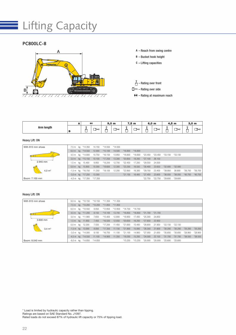
PC800-8
Lifting Capacity
A
B
C
– Reach from swing centre
– Bucket hook height
– Lifting capacities
– Rating over front
– Rating over side
– Rating at maximum reachCB
A
7,5 m kg *14.050 13.300 *14.250 13.950
6,0 m kg *14.250 11.200 *14.800 13.650 *16.500 *16.500
4,5 m kg 12.900 10.000 *15.800 13.100 *18.450 18.400 *23.100 *23.100 *32.850 *32.850
3,0 m kg 12.200 9.350 16.050 12.450 *20.500 17.200 *26.750 24.900
1,5 m kg 12.050 9.200 15.400 11.850 21.050 16.200 *29.200 23.250
0,0 m kg 12.500 9.500 15.000 11.450 20.350 15.550 29700 22.350 *31.650 *31.650
-1,5 m kg 13.700 10.450 14.850 11.350 20.100 15.300 *29.400 22.100 *39.550 37.000 *26.400 *26.400
-3,0 m kg 16.250 12.450 20.200 15.400 *27.100 22.350 *35.700 *35.700 *40.350 *40.350
-4,5 m kg *17.000 16.800 *22.400 *22.400 *29.250 *29.250
Arm length
9,0 m 7,5 m 6,0 m 4,5 m 3,0 m
2.945 mm
4,3 m3
With 610 mm shoes
Boom: 7.100 mm
Heavy Lift: ON
9,0 m kg *10.150 *10.150 *11.350 *11.350
7,5 m kg *10.200 10.050 *11.850 *11.850
6,0 m kg *10.550 8.650 *12.850 *12.850 *14.750 *14.750
4,5 m kg 10.200 7.750 *14.100 13.100 *16.850 *16.850 *21.700 *21.700
3,0 m kg 9.600 7.250 *15.400 12.250 *18.950 16.700 *25.300 23.850
1,5 m kg 9.400 7.000 15.000 11.450 20.350 15.500 *27.650 21.950
0,0 m kg 9.600 7.100 14.400 10.900 19.450 14.650 28.200 20.950 *22.150 *22.150
-1,5 m kg 10.200 7.600 14.050 10.550 19.000 14.250 27.800 20.600 *30.200 *30.200 *20.200 *20.200
-3,0 m kg 11.500 8.600 14.000 10.500 18.950 14.200 *27.050 20.650 *35.650 35.050 *28.900 *28.900
-4,5 m kg 14.000 10.550 14.300 10.800 *19.200 14.450 *24.500 21.150 *31.700 *31.700 *38.550 *38.550
-6,0 m kg *14.850 14.850 *15.250 15.200 *20.000 *20.000 *25.600 *25.600
With 610 mm shoes
Boom: 8.040 mm
Heavy Lift: ON
3.600 mm
3,4 m3
* Load is limited by hydraulic capacity rather than tipping.
Ratings are based on SAE Standard No. J1097.
Rated loads do not exceed 87% of hydraulic lift capacity or 75% of tipping load.
22
Lifting CapacityPC800LC-8
A
B
C
– Reach from swing centre
– Bucket hook height
– Lifting capacities
– Rating over front
– Rating over side
– Rating at maximum reach
7,5 m kg *14.350 14.150 *14.550 *14.550
6,0 m kg *14.550 12.000 *15.100 14.500 *16.800 *16.800
4,5 m kg *14.800 10.750 *16.150 13.950 *18.800 *18.800 *23.450 *23.450 *33.150 *33.150
3,0 m kg *15.150 10.100 *17.250 13.300 *20.850 18.200 *27.100 26.150
1,5 m kg 15.400 9.950 *18.200 12.700 *22.450 17.200 *29.550 24.500
0,0 m kg 15.950 10.300 *18.600 12.300 *23.200 16.550 *30.400 23.650 *32.000 *32.000
-1,5 m kg *16.750 11.250 *18.100 12.200 *22.950 16.300 *29.750 23.400 *39.950 38.900 *26.700 *26.700
-3,0 m kg *17.250 13.300 *21.150 16.400 *27.450 23.600 *36.050 *36.050 *40.700 *40.700
-4,5 m kg *17.350 *17.350 *22.750 *22.750 *29.600 *29.600
Arm length
9,0 m 7,5 m 6,0 m 4,5 m 3,0 m
With 810 mm shoes
Boom: 7.100 mm
Heavy Lift: ON
9,0 m kg *10.150 *10.150 *11.350 *11.350
7,5 m kg *10.200 *10.200 *11.850 *11.850
6,0 m kg *10.550 9.050 *12.850 *12.850 *14.750 *14.750
4,5 m kg *11.200 8.150 *14.100 13.700 *16.850 *16.850 *21.700 *21.700
3,0 m kg *11.900 7.650 *15.400 12.800 *18.950 17.450 *25.300 24.850
1,5 m kg 11.950 7.450 *16.500 12.050 *20.650 16.200 *27.650 22.950
0,0 m kg 12.200 7.550 *17.200 11.450 *21.600 15.400 *28.600 21.950 *22.150 *22.150
-1,5 m kg 13.000 8.050 *17.350 11.150 *21.800 15.000 *28.350 21.600 *30.200 *30.200 *20.200 *20.200
-3,0 m kg *14.000 9.100 *16.750 11.100 *21.100 14.900 *27.050 21.650 *35.650 *35.650 *28.900 *28.900
-4,5 m kg *14.550 11.100 *14.900 11.350 *19.200 15.200 *24.500 22.150 *31.700 *31.700 *38.550 *38.550
-6,0 m kg *14.850 *14.850 *15.250 *15.250 *20.000 *20.000 *25.600 *25.600
With 810 mm shoes
Boom: 8.040 mm
Heavy Lift: ON
* Load is limited by hydraulic capacity rather than tipping.
Ratings are based on SAE Standard No. J1097.
Rated loads do not exceed 87% of hydraulic lift capacity or 75% of tipping load.
CB
A
2.945 mm
4,0 m3
3.600 mm
3,4 m3

23
Notes
Komatsu Europe
International NVMechelsesteenweg 586
B-1800 VILVOORDE (BELGIUM)
Tel. +32-2-255 24 11
Fax +32-2-252 19 81
www.komatsu.eu
Materials and specifi cations are subject to change without notice.
is a trademark of Komatsu Ltd. Japan.
UESS11804 09/2010
Printed in Europe – This specifi cation sheet may contain attachments and optional equipment that are not available in your area.
Please consult your local Komatsu distributor for those items you may require. Materials and specifi cations are subject to change without notice.
Standard and Optional Equipment
Your Komatsu partner:
PC800-8/LC-8Hydraulic Excavator
Further equipment on request
standard equipment optional equipment
ENGINEKomatsu SAA6D140E-5, 370 kW turbocharged
common rail direct injection diesel engine,
EU Stage IIIA compliant
Radiator & oil cooler with fl y net
Automatic engine warm-up system
Engine overheat prevention system
Cooling fan: remote hydraulically driven variable
speed, reversible
Auto-deceleration function
Engine ignition can be password secured on
request
Alternator 24 V/75 A
Starter motor 24 V/11 kW
Batteries 2 × 12 V/240 Ah
HYDRAULIC SYSTEMElectronic Open-centre load sensing (E-OLSS)
hydraulic system
Pump and engine mutual control (PEMC) system
Working mode selection system (power mode,
economy mode)
In-line fi lter for hydraulics
Adjustable PPC wrist control levers with 3 button
controls for arm, boom, bucket and swing
Heavy lift mode
2 mode boom control
Additional hydraulic function (preparation), double
acting (2 way fl ow) only
(not with boom and arm safety valves)
DRIVES AND BRAKESHydrostatic, 2-speed travel system with automatic
shift and planetary triple reduction fi nal drives, and
hydraulic travel and oil disc parking brakes
PPC control levers and pedals for steering and
travel
CABINSpaceCab™; highly pressurised and tightly sealed
viscous mounted cab with tinted safety glass
windows, opening roof hatch with window, pull-up
type front window with locking device, removable
lower window, front window wiper with intermittent
feature, ashtray, luggage box, fl oor mat, cigarette
lighter, sun roller blind, bottle holder & magazine
rack
Fully adjustable heated air suspension seat
Air conditioning
12 Volt power supply
Stereo radio cassette
Lower wiper
Rain visor (not with OPG)
SERVICE AND MAINTENANCEAutomatic fuel line de-aeration
Double element type air cleaner with dust indicator
and auto dust evacuator
KOMTRAX™ - Komatsu satellite monitoring system
Multi-function colour monitor with equipment
management monitoring system (EMMS)
Toolkit and spare parts for fi rst service
SAFETY EQUIPMENTLockable fuel cap and covers
Audible travel alarm
Machine cab handrails and catwalk
Step light with timer
Battery main switch
Boom safety valves
(not with additional hydraulic function)
Arm safety valves (only with boom safety valves)
OPG Level II front guard (FOPS)
OPG Level II top guard (FOPS)
LIGHTING SYSTEMAdditional cab roof lights
Beacon
OTHER EQUIPMENTRemote greasing for swing circle and pins
Standard colour scheme and decals
Parts book and operator manual
Biodegradable oil for hydraulic system
UNDERCARRIAGETrack frame undercovers
LC undercarriage
610, 710, 810, 910, 1.010, 1.110 mm
wide double grouser shoes
Extra additional track roller guard
(2 per side is std.)
Full length track roller guards
WORK EQUIPMENT8,0 m boom and 3,6 m arm
7,1 m boom and 2,9 m arm