hydraulic dock leveler - wbmcguire.com · keep pedestrians and forklifts away from open door area...
TRANSCRIPT
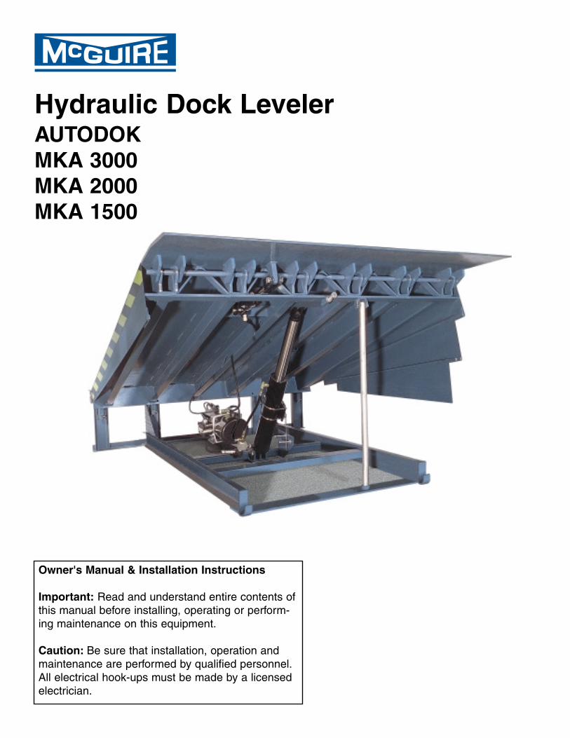
Hydraulic Dock Leveler AUTODOK
MKA 3000
MKA 2000
MKA 1500
Owner's Manual & Installation Instructions
Important: Read and understand entire contents of
this manual before installing, operating or perform-
ing maintenance on this equipment.
Caution: Be sure that installation, operation and
maintenance are performed by qualified personnel.
All electrical hook-ups must be made by a licensed
electrician.
TABLE OF CONTENTS
Introduction ...........................................................................................................................................
Overview of Potential Hazards ............................................................................................................
Definition & Function-, Safety Practices ..............................................................................................
Installation Instructions ......................................................................................................................
Pit Detail & Dimensions ........................................................................................................................
Shim Location Diagram ........................................................................................................................
Electrical Schematics ......................................................................................................................
Dock Bumper Mounting ......................................................................................................................
Operation Instructions ...................................................................................................................
Setting the Inspection Leg ..................................................................................................................
Maintenance & Service .......................................................................................................................
Trouble Shooting Procedures .............................................................................................................
Control Valves & Motor Pump Adjustments .......................................................................................
Switch Arrangements .........................................................................................................................
Hydraulic System View & Parts List ..................................................................................................
Control Panel View & Parts List ........................................................................................................
Warranty ..............................................................................................................................
INTRODUCTION
Congratulations! You have just purchased one of the industry's finest hydraulically operated dock lev-
elers from the W.B. McGuire Company Inc. of Hudson, NY When properly installed, operated and
serviced, this leveler can offer substantial efficiency and productivity. This McGuire hydraulic dock
leveler is the result of many skilled workers and its design, manufacture, and full hydraulic operation
are regarded with pride by the W.B. McGuire Company, Inc.
This hydraulic dock leveler by McGuire is designed to improve safety and efficiency for personnel
involved in shipping and receiving goods at the loading dock area. Improved safety conditions are
achieved by use of the control panel to operate the dock leveler. This reduces the risk of injury by
keeping personnel off of the leveler and eliminates the unhealthy practice of manually positioning the
leveler. Efficiency is the result of quicker operation, and a more reliable hydraulic operating system.
This system requires minimal maintenance and provides you with years of dependable service.
All safety considerations should be observed by all those who install, operate and service this equip-
ment. Even well-built products can be installed, operated and serviced in a less than safe manner.
Read this manual completely through to understand all installation, operation and maintenance
instructions and functions before attempting to install, operate or service this hydraulic dock leveler.
Pay special attention to all warnings and/or caution statements.
1
1
2
3
4-5
6
7
8-11
12
13-14
15
16
18
19
20
21
22
Back Cover
WARNING!
SAFETY INSTRUCTIONS
In the following sections the word:
Danger means that serious injury or death will occur from failure to follow instructions.
Warning means that serious injury or death can occur from failure to follow instructions.
Caution means that minor injury or property damage can occur from failure to follow instructions.
Note means that special attention should be given to the instruction.
2
1. Read manual carefully before installing, operating, or servicing dock leveler.
2. Be sure truck wheels are chocked or truck is held in place by a restraining device before loading or unloading.
3. Make sure leveler is returned to its level, stored position after truck pulls away from dock.
4. Do not attempt to manually lift the dock leveler platform or lip. Do Not operate leveler with equipment, material
or people on the platform, lip or in front of the leveler.
5. Keep pedestrians and forklifts away from open door area when not loading or unloading truck.
6. If dock leveler appears to be broken or is not working properly, contact your authorized McGuire representative.
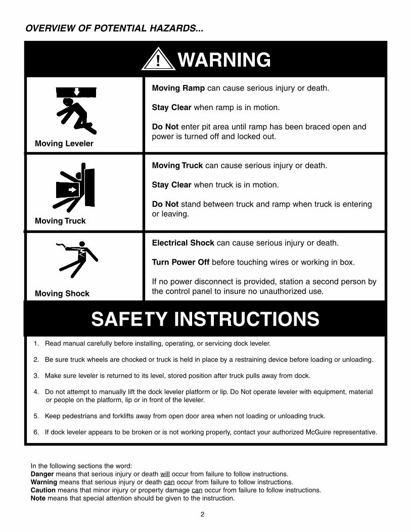
Moving Ramp can cause serious injury or death.
Stay Clear when ramp is in motion.
Do Not enter pit area until ramp has been braced open and
power is turned off and locked out.
Moving Truck can cause serious injury or death.
Stay Clear when truck is in motion.
Do Not stand between truck and ramp when truck is entering
or leaving.
Electrical Shock can cause serious injury or death.
Turn Power Off before touching wires or working in box.
If no power disconnect is provided, station a second person by
the control panel to insure no unauthorized use.
Moving Leveler
Moving Truck
Moving Shock
OVERVIEW OF POTENTIAL HAZARDS...
DEFINITION AND FUNCTION
The McGuire hydraulic dock leveler is designed for both structural integrity in operation and safety
features for the protection of dock personnel. Its function is to provide a safe and durable bridge
between the building and the trailer. This bridge allows the safe transportation of material handling
devices (i.e. fork truck, pallet jack, hand truck) and workers for the purpose of loading and unloading
the trailer.
All McGuire hydraulic levelers are equipped with a velocity fuse "Fail-Safe" system which automati-
cally halts all motion of the platform, within 1 " to 3", if a truck prematurely departs with a load on the
platform. Other safety features include full-range toe guards that are safety marked, a built-in service
leg support and an automatic night lock feature to aid in the prevention of possible break-in attempts
through the dock area.
The leveler is push button operated from a wall mount control panel and is fully electro-hydraulic
operated. Models can be equipped with an Emergency Stop button which halts all movement of the
leveler at any point during the cycle. A selector switch on the control panel allows automatic posi-
tiong for below dock end load situations.
The unit is powered by a 1 horsepower single or polyphase electric motor with manifold block and a
reservoir that is directly coupled to the motor via the manifold block. The main lift cylinder raises and
lowers the platform. The lip cylinder extends, supports and retracts the lip. Flexible hosing connects
both cylinders to the power unit.
Electrical leads from motor/pump and integral control switches are factory wired, ready to hook up to
leads in the junction box at the rear of the pit. The control panel is wired to work in conjunction with
the motor/pump. Connections between terminals in the control panel and the pit junction box are not
furnished by McGuire. This must be done prior to installing this hydraulic leveler. Connections
between terminals in the control panel and the main power line are also not furnished by McGuire.
SAFETY PRACTICES
1. Do not operate this equipment while under the influence of drugs or alcohol.
2. Do not stand in the driveway between the leveler and a moving truck.
3. Be sure that the trailer wheels are chocked or restraint device is positioned.
4. Do not use the leveler if appears to be broken or operating improperly.
5. Do not operate the leveler with equipment, material or people on the platform.
6. Be certain that nothing is on the leveler while a truck pulls away from the dock.
7. Keep all limbs clear of the leveler while it is in motion.
8. Do not attempt to manually lift the leveler platform.
9. Always make sure the leveler has been returned to the dock level (stored) position.
10. Never work under the dock leveler without proper placement of the service leg.
11. When servicing leveler, disconnect power and tag control panel "Out of Service."
Place a barrier on grade level in front of the leveler to prevent any truck from backing to the dock.
Contact the McGuire Technical Support Team at 1-800-624-8473 if you have any
questions or do not understand any material presented in this manual.
3
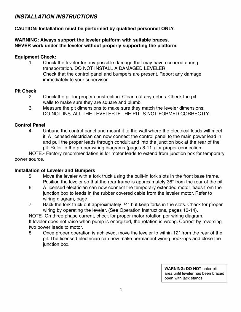
INSTALLATION INSTRUCTIONS
CAUTION: Installation must be performed by qualified personnel ONLY.
WARNING: Always support the leveler platform with suitable braces.
NEVER work under the leveler without properly supporting the platform.
Equipment Check:
1. Check the leveler for any possible damage that may have occurred during
transportation. DO NOT INSTALL A DAMAGED LEVELER.
Check that the control panel and bumpers are present. Report any damage
immediately to your supervisor.
Pit Check
2. Check the pit for proper construction. Clean out any debris. Check the pit
walls to make sure they are square and plumb.
3. Measure the pit dimensions to make sure they match the leveler dimensions.
DO NOT INSTALL THE LEVELER IF THE PIT IS NOT FORMED CORRECTLY.
Control Panel
4. Unband the control panel and mount it to the wall where the electrical leads will meet
it. A licensed electrician can now connect the control panel to the main power lead in
and pull the proper leads through conduit and into the junction box at the rear of the
pit. Refer to the proper wiring diagrams (pages 8-11 ) for proper connection.
NOTE.- Factory recommendation is for motor leads to extend from junction box for temporary
power source.
Installation of Leveler and Bumpers
5. Move the leveler with a fork truck using the built-in fork slots in the front base frame.
Position the leveler so that the rear frame is approximately 36" from the rear of the pit.
6. A licensed electrician can now connect the temporary extended motor leads from the
junction box to leads in the rubber covered cable from the leveler motor. Refer to
wiring diagram, page
7. Back the fork truck out approximately 24" but keep forks in the slots. Check for proper
wiring by operating the leveler. (See Operation Instructions, pages 13-14).
NOTE- On three phase current, check for proper motor rotation per wiring diagram.
If leveler does not raise when pump is energized, the rotation is wrong. Correct by reversing
two power leads to motor.
8. Once proper operation is achieved, move the leveler to within 12" from the rear of the
pit. The licensed electrician can now make permanent wiring hook-ups and close the
junction box.
4
WARNING: DO NOT enter pit
area until leveler has been braced
open with jack stands.
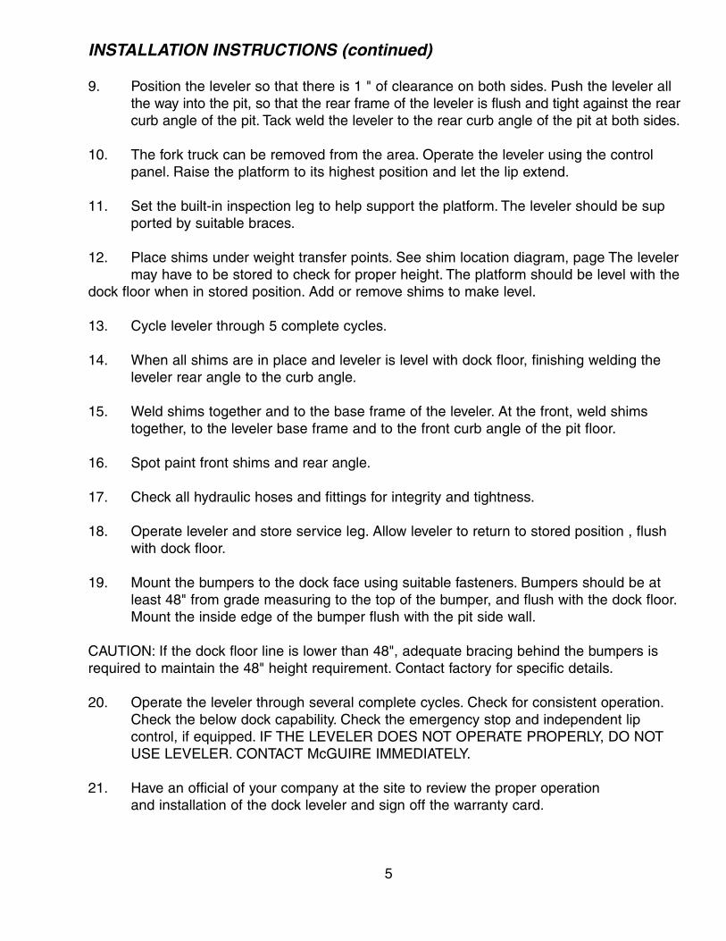
INSTALLATION INSTRUCTIONS (continued)
9. Position the leveler so that there is 1 " of clearance on both sides. Push the leveler all
the way into the pit, so that the rear frame of the leveler is flush and tight against the rear
curb angle of the pit. Tack weld the leveler to the rear curb angle of the pit at both sides.
10. The fork truck can be removed from the area. Operate the leveler using the control
panel. Raise the platform to its highest position and let the lip extend.
11. Set the built-in inspection leg to help support the platform. The leveler should be sup
ported by suitable braces.
12. Place shims under weight transfer points. See shim location diagram, page The leveler
may have to be stored to check for proper height. The platform should be level with the
dock floor when in stored position. Add or remove shims to make level.
13. Cycle leveler through 5 complete cycles.
14. When all shims are in place and leveler is level with dock floor, finishing welding the
leveler rear angle to the curb angle.
15. Weld shims together and to the base frame of the leveler. At the front, weld shims
together, to the leveler base frame and to the front curb angle of the pit floor.
16. Spot paint front shims and rear angle.
17. Check all hydraulic hoses and fittings for integrity and tightness.
18. Operate leveler and store service leg. Allow leveler to return to stored position , flush
with dock floor.
19. Mount the bumpers to the dock face using suitable fasteners. Bumpers should be at
least 48" from grade measuring to the top of the bumper, and flush with the dock floor.
Mount the inside edge of the bumper flush with the pit side wall.
CAUTION: If the dock floor line is lower than 48", adequate bracing behind the bumpers is
required to maintain the 48" height requirement. Contact factory for specific details.
20. Operate the leveler through several complete cycles. Check for consistent operation.
Check the below dock capability. Check the emergency stop and independent lip
control, if equipped. IF THE LEVELER DOES NOT OPERATE PROPERLY, DO NOT
USE LEVELER. CONTACT McGUIRE IMMEDIATELY.
21. Have an official of your company at the site to review the proper operation
and installation of the dock leveler and sign off the warranty card.
5
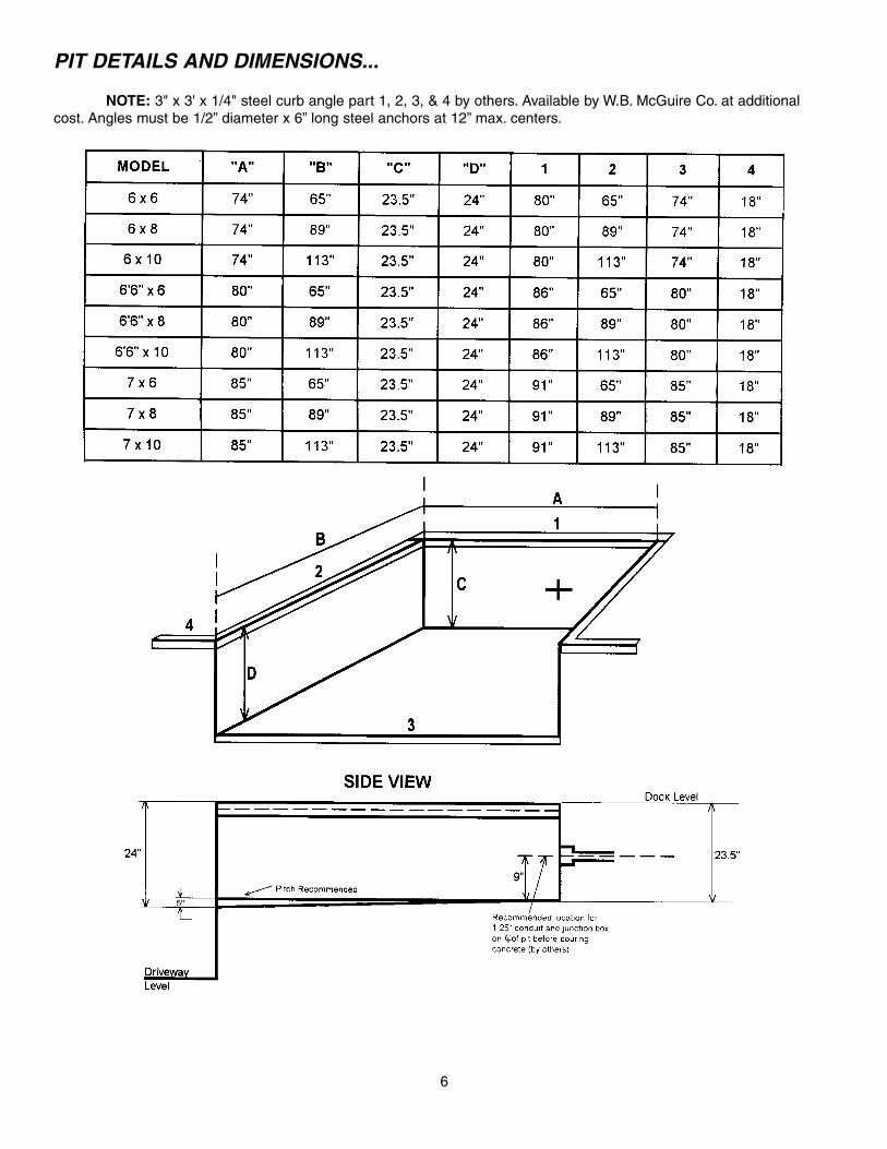
PIT DETAILS AND DIMENSIONS...
NOTE: 3" x 3' x 1/4" steel curb angle part 1, 2, 3, & 4 by others. Available by W.B. McGuire Co. at additional
cost. Angles must be 1/2” diameter x 6” long steel anchors at 12” max. centers.
6
7
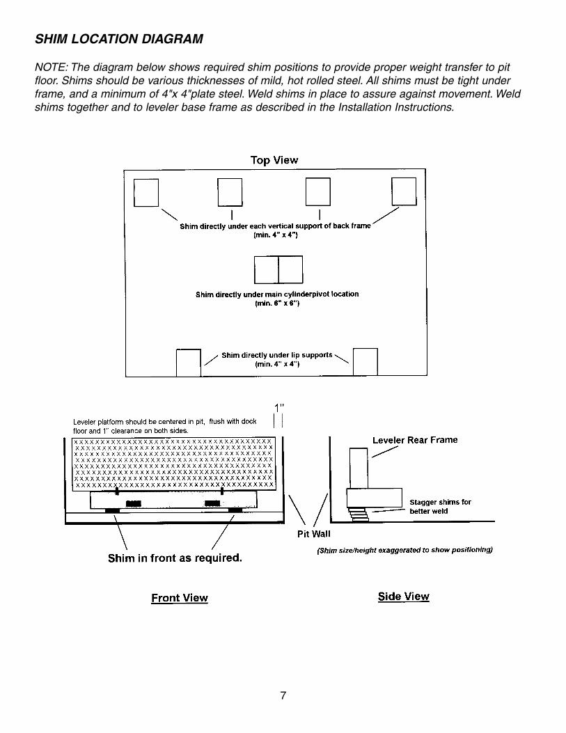
SHIM LOCATION DIAGRAM
NOTE: The diagram below shows required shim positions to provide proper weight transfer to pit
floor. Shims should be various thicknesses of mild, hot rolled steel. All shims must be tight under
frame, and a minimum of 4"x 4"plate steel. Weld shims in place to assure against movement. Weld
shims together and to leveler base frame as described in the Installation Instructions.
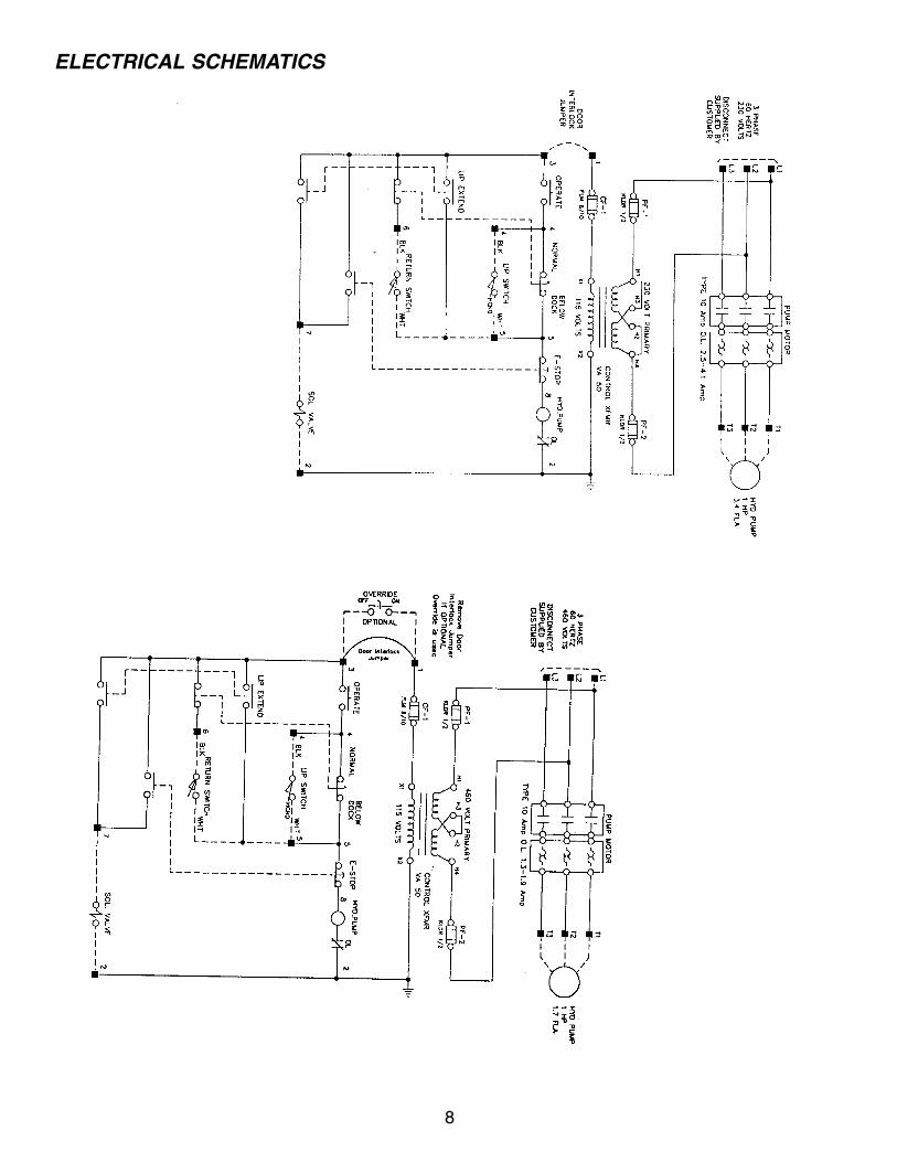
ELECTRICAL SCHEMATICS
8
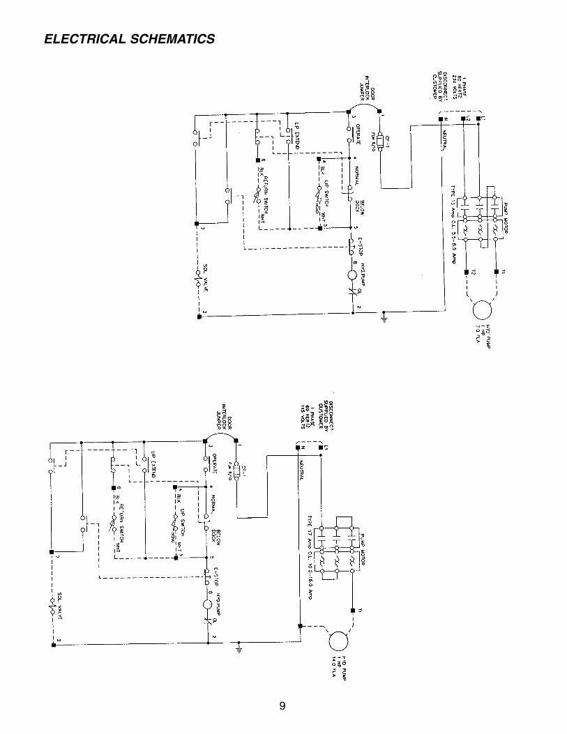
ELECTRICAL SCHEMATICS
9
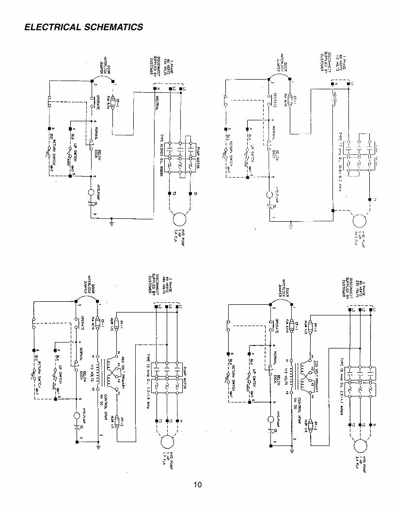
ELECTRICAL SCHEMATICS
10
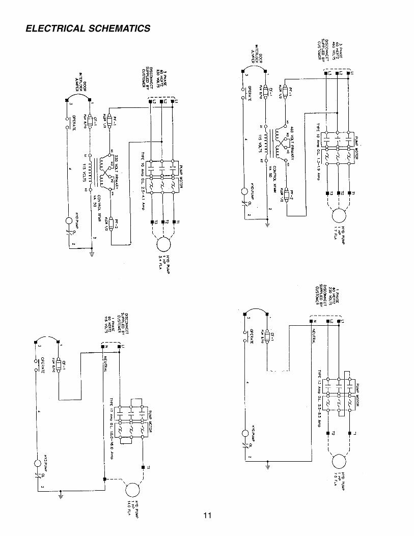
ELECTRICAL SCHEMATICS
11
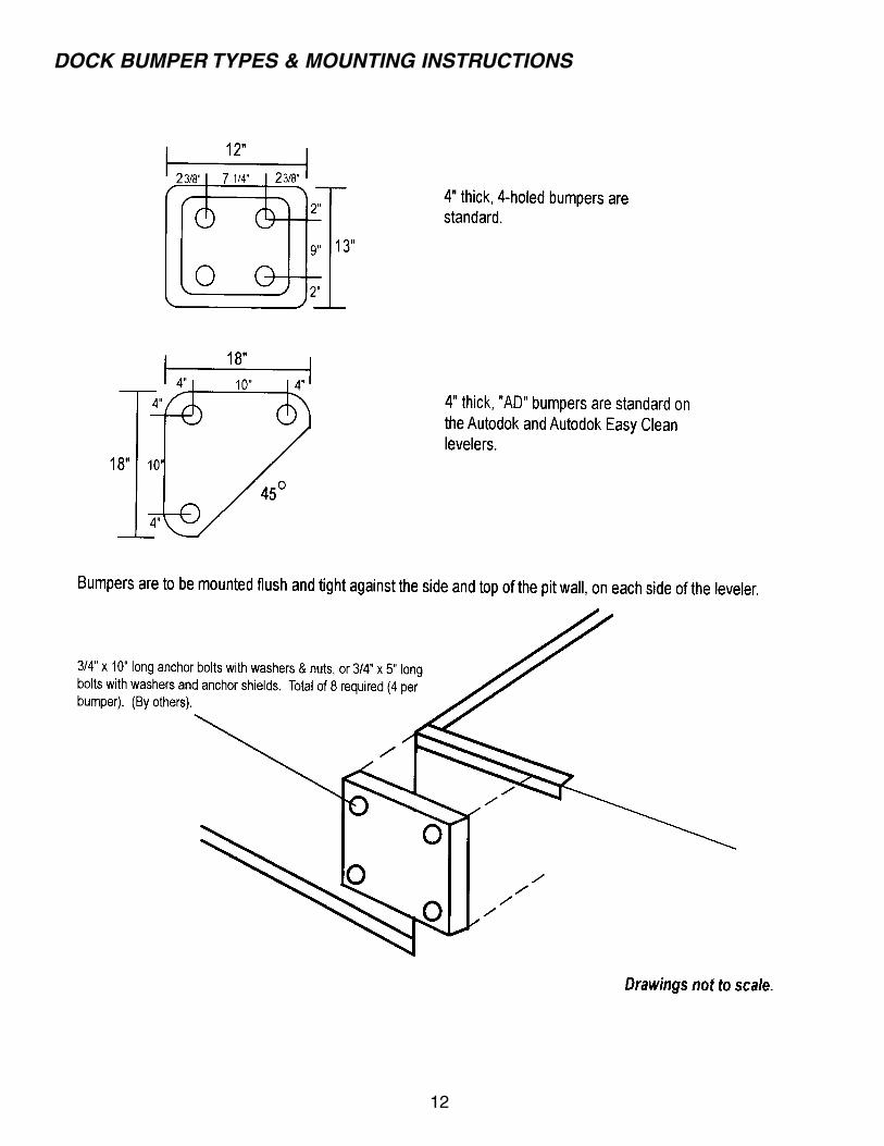
DOCK BUMPER TYPES & MOUNTING INSTRUCTIONS
12
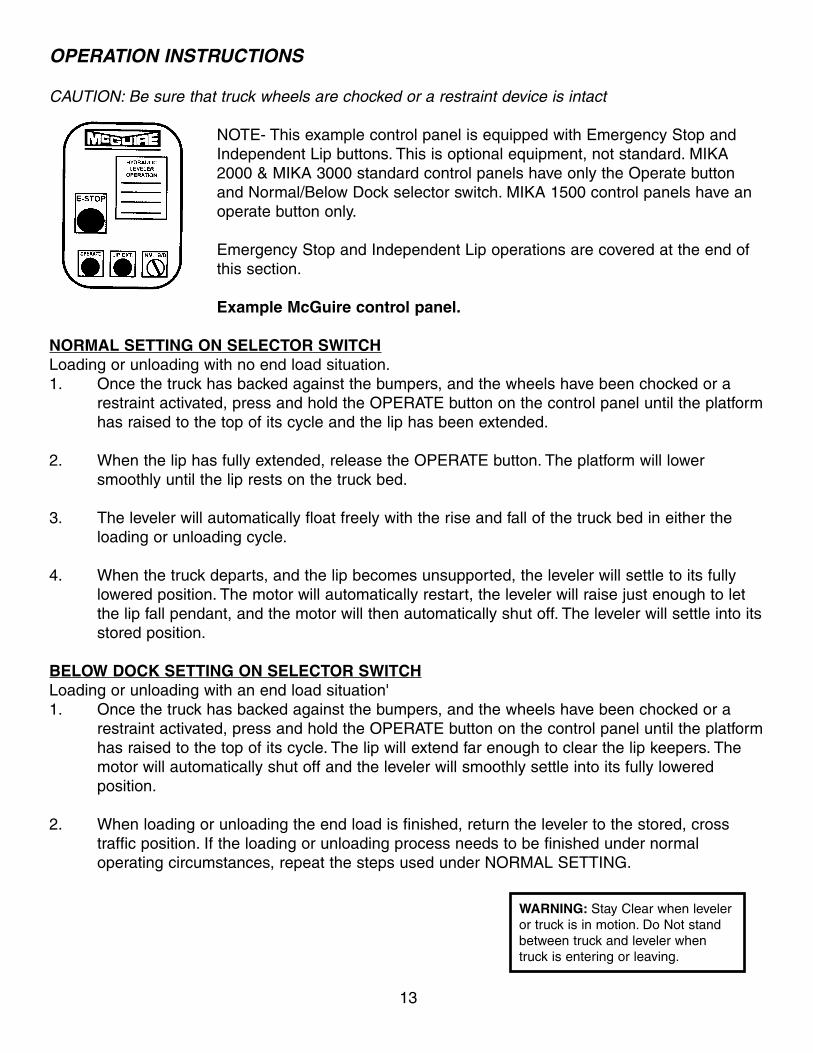
OPERATION INSTRUCTIONS
CAUTION: Be sure that truck wheels are chocked or a restraint device is intact
NOTE- This example control panel is equipped with Emergency Stop and
Independent Lip buttons. This is optional equipment, not standard. MIKA
2000 & MIKA 3000 standard control panels have only the Operate button
and Normal/Below Dock selector switch. MIKA 1500 control panels have an
operate button only.
Emergency Stop and Independent Lip operations are covered at the end of
this section.
Example McGuire control panel.
NORMAL SETTING ON SELECTOR SWITCH
Loading or unloading with no end load situation.
1. Once the truck has backed against the bumpers, and the wheels have been chocked or a
restraint activated, press and hold the OPERATE button on the control panel until the platform
has raised to the top of its cycle and the lip has been extended.
2. When the lip has fully extended, release the OPERATE button. The platform will lower
smoothly until the lip rests on the truck bed.
3. The leveler will automatically float freely with the rise and fall of the truck bed in either the
loading or unloading cycle.
4. When the truck departs, and the lip becomes unsupported, the leveler will settle to its fully
lowered position. The motor will automatically restart, the leveler will raise just enough to let
the lip fall pendant, and the motor will then automatically shut off. The leveler will settle into its
stored position.
BELOW DOCK SETTING ON SELECTOR SWITCH
Loading or unloading with an end load situation'
1. Once the truck has backed against the bumpers, and the wheels have been chocked or a
restraint activated, press and hold the OPERATE button on the control panel until the platform
has raised to the top of its cycle. The lip will extend far enough to clear the lip keepers. The
motor will automatically shut off and the leveler will smoothly settle into its fully lowered
position.
2. When loading or unloading the end load is finished, return the leveler to the stored, cross
traffic position. If the loading or unloading process needs to be finished under normal
operating circumstances, repeat the steps used under NORMAL SETTING.
WARNING: Stay Clear when leveler
or truck is in motion. Do Not stand
between truck and leveler when
truck is entering or leaving.
13
OPERATION INSTRUCTIONS CONTINUED
OPERATION WITH EXTREMELY LOW TRUCK BEDS These instructions are intended to be followed when it is necessary to service extremely low trucks
with no end load and the lip must be extended.
1. Once the truck has backed against the bumpers, and the wheels have been chocked
or a restraint activated, set the selector switch to NORMAL, press and hold the
OPERATE button until the platform rises to the top of its cycle and the lip has extended.
2. When the leveler lip has fully extended, release the OPERATE button. The deck will
start to lower with lip extended. Turn the selector switch to BELOW DOCK. The leveler
will settle to its fully lowered position with the lip fully extended.
3. When loading or unloading is finished, return the leveler to the stored, cross
traffic position.
STORING THE LEVELER WITH A TRUCK AT THE DOCK
1. The leveler will be positioned on the bed of the truck.
2. With the selector switch in the NORMAL position, press and hold the OPERATE
button.
3. As the leveler begins to rise, the lip will fall pendant. At this point, release the
OPERATE button and the leveler will return to the stored, cross traffic position.
INDEPENDENT LIP OPERATION (IF EQUIPPED)
1. Once the truck has backed against the bumpers, and the wheels have been chocked
or a restraint activated, set selector switch to NORMAL. Press and hold the OPERATE
button. When the leveler has reached the desired position, release the OPERATE
button and immediately press and hold the LIP EXTEND button.
2. Once the lip has fully extended, release the LIP EXTEND button and deck will settle on
to truck bed with lip extended.
EMERGENCY STOP (IF EQUIPPED)
1. The EMERGENCY STOP button can be pushed at any point of the leveler's cycle to
immediately halt any and all movement of the leveler. Pull the button out to resume
action.
14
OPERATION INSTRUCTIONS CONTINUED
OPERATION WITH EXTREMELY LOW TRUCK BEDS These instructions are intended to be followed when it is necessary to service extremely low trucks
with no end load and the lip must be extended.
1. Once the truck has backed against the bumpers, and the wheels have been
chocked or a restraint activated, set the selector switch to NORMAL, press
and hold the OPERATE button until the platform rises to the top of its cycle
and the lip has extended.
2. When the leveler lip has fully extended, release the OPERATE button. The
deck will start to lower with lip extended. Turn the selector switch to BELOW
DOCK. The leveler will settle to its fully lowered position with the lip fully
extended.
3. When loading or unloading is finished, return the leveler to the stored, cross
traffic position.
STORING THE LEVELER WITH A TRUCK AT THE DOCK
1. The leveler will be positioned on the bed of the truck.
2. With the selector switch in the NORMAL position, press and hold the
OPERATE button.
3. As the leveler begins to rise, the lip will fall pendant. At this point, release
the OPERATE button and the leveler will return to the stored, cross traffic
position.
INDEPENDENT LIP OPERATION (IF EQUIPPED)
1. Once the truck has backed against the bumpers, and the wheels have been
chocked or a restraint activated, set selector switch to NORMAL. Press and
hold the OPERATE button. When the leveler has reached the desired position
release the OPERATE button and immediately press and hold the LIP
EXTEND button.
2. Once the lip has fully extended, release the LIP EXTEND button and deck
will settle on to truck bed with lip extended.
EMERGENCY STOP (IF EQUIPPED)
1. The EMERGENCY STOP button can be pushed at any point of the leveler's cycle to
immediately halt any and all movement of the leveler. Pull the button out to resume
action.
14
SETTING THE BUILT-IN INSPECTION LEG
The inspection leg is a built-in steel pipe which, when set in place properly, will support the platform
in an upright position. For qualified personnel to perform maintenance or service, the platform should
be supported with adequate bracing. Setting the inspection leg requires two people.
CAUTION: The inspection leg is meant to support the weight of the platform only,
1. Tag the control panel "Out of Service'' to prevent accidental operation of the
leveler.
2. Place barriers on grade level in front of the leveler to prevent trucks from
backing to the dock.
3. Have one attendant raise the leveler platform using the OPERATE button.
Keep the button depressed until the second attendant gives the "OK" to
release.
4. The second attendant can unhook the inspection leg and set it in its vertical position.
Once set, the second attendant can give the "OK" and the first attendant can release
the OPERATE button. As an additional safety measure, press the EMERGENCY STOP
button (if equipped) to cut all power to the leveler.
5. To store the inspection leg, pull the EMERGENCY STOP button (if equipped), press
and hold the OPERATE button until the platform rises to the top of its cycle and the lip
is fully extended. Keep the button depressed until the second attendant gives the "OK"
to release.
6. The second attendant can re-hook the inspection leg to its stored position.
Once set, the second attendant can give the "OK" and the first attendant can
release the OPERATE button. The leveler will return to the stored, cross
traffic position.
NOTE: NEVER WORK UNDER THE LEVELER WITHOUT
PROPERLY SUPPORTING THE PLATFORM WITH ADEQUATE BRACES.
DO NOT PUT ANYTHING ON THE LEVELER PLATFORM WHILE
THE INSPECTION LEG IS SUPPORTING THE PLATFORM.
MAKE SURE CO-WORKERS KNOW NOT TO OPERATE THE LEVELER
WHILE MAINTENANCE OR SERVICE IS BEING PERFORMED.
15
WARNING: DO NOT enter pit area
until leveler has been braced open
with jack stands.
MAINTENANCE AND SERVICE
On-site maintenance personnel can observe the following
procedures or you can arrange for professional service through your authorized McGuire representative.
The frequency of maintenance and service required will vary due to the amount and type of usage.
Contact your authorized McGuire representative of the factory for information.
Authorization to repair, replace or otherwise adjust any portion of the dock leveler should always be
secured in advance of any work taking place. Failure to do so could VOID the dock leveler warranty.
1. Follow the procedures for Setting the Built-in Inspection Leg.
2. Clean any debris from the pit. Clear the hinge areas of any collected debris. During winter
months in cold climate, remove any ice formed on moving parts.
3. Inspect the condition of lip, platform, subframe and all welds for wear and/or damage. Report
any deficiencies immediately. If in doubt, report it!
4. Check conditions of front and rear hinges. Report any deficiencies.
5. Check the fluid level in the motor/pump reservoir using the dipstick on the breather cap. If
necessary, add proper fluid. Replace the breather cap.
6. Check integrity of ail hydraulic hoses and fittings for tightness. Replace or tighten as needed.
7. Inspect all hydraulic cylinders and switches for damage or wear. Replace as required.
8. Inspect and lubricate all cylinder pivots.
9. Check weatherseals for damage or signs of wear. Replace as required.
10. Inspect toe guards for damage. Replace as required.
11. Inspect all electrical connections and wiring for signs of wear or damage. Report
any deficiencies. Have only a licensed electrician make repairs.
12. Check safety tape markings. Replace as required.
13. Check all labels and warnings. Replace as required.
14. Inspect bumpers for wear. Check fasteners. Tighten, or replace as required.
15. Follow the instructions for storing the service leg.
16. Once leveler is returned to the stored position, operate the leveler following the Operation
Instructions. Run the leveler through several complete cycles. IF LEVELER IS NOT OPERATING
PROPERLY, DO NOT USE THE LEVELER. CONTACT YOUR AUTHORIZED REPRESENTATIVE
OR THE FACTORY IMMEDIATELY.
16
WARNING: DO NOT enter pit area
until leveler has been braced open
with jack stands.
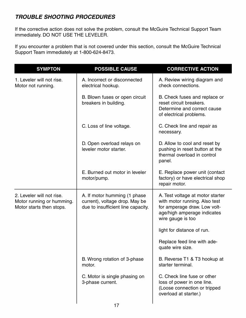
TROUBLE SHOOTING PROCEDURES
If the corrective action does not solve the problem, consult the McGuire Technical Support Team
immediately. DO NOT USE THE LEVELER.
If you encounter a problem that is not covered under this section, consult the McGuire Technical
Support Team immediately at 1-800-624-8473.
1. Leveler will not rise.
Motor not running.
2. Leveler will not rise.
Motor running or humming.
Motor starts then stops.
A. Incorrect or disconnected
electrical hookup.
B. Blown fuses or open circuit
breakers in building.
C. Loss of line voltage.
D. Open overload relays on
leveler motor starter.
E. Burned out motor in leveler
motor/pump.
A. If motor humming (1 phase
current), voltage drop. May be
due to insufficient line capacity.
B. Wrong rotation of 3-phase
motor.
C. Motor is single phasing on
3-phase current.
17
A. Review wiring diagram and
check connections.
B. Check fuses and replace or
reset circuit breakers.
Determine and correct cause
of electrical problems.
C. Check line and repair as
necessary.
D. Allow to cool and reset by
pushing in reset button at the
thermal overload in control
panel.
E. Replace power unit (contact
factory) or have electrical shop
repair motor.
A. Test voltage at motor starter
with motor running. Also test
for amperage draw. Low volt-
age/high amperage indicates
wire gauge is too
light for distance of run.
Replace feed line with ade-
quate wire size.
B. Reverse T1 & T3 hookup at
starter terminal.
C. Check line fuse or other
loss of power in one line.
(Loose connection or tripped
overload at starter.)
SYMPTON POSSIBLE CAUSE CORRECTIVE ACTION
SYMPTON POSSIBLE CAUSE CORRECTIVE ACTION
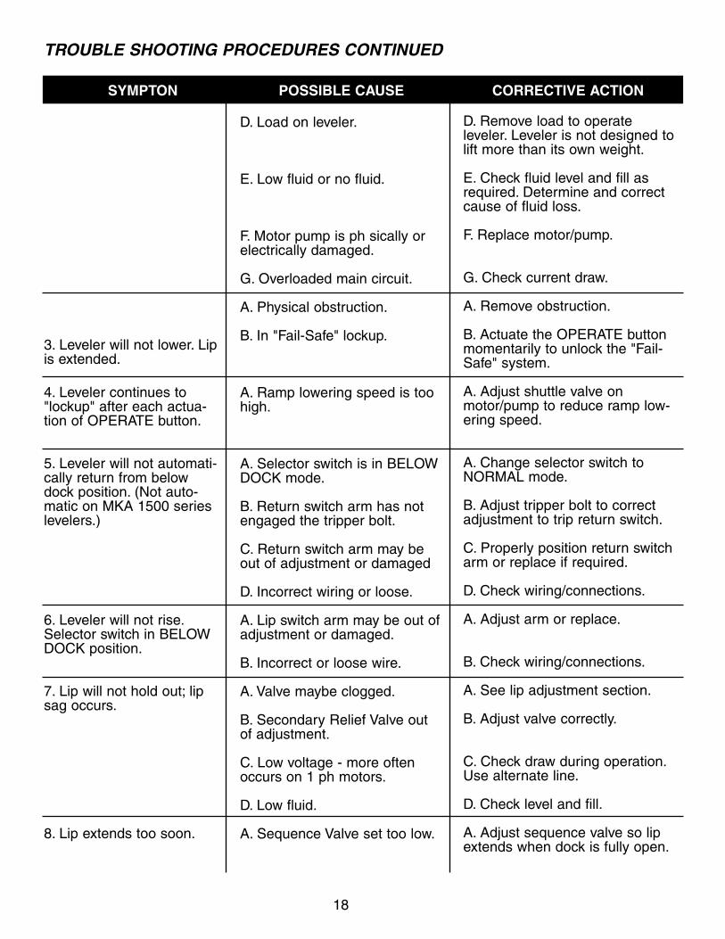
TROUBLE SHOOTING PROCEDURES CONTINUED
3. Leveler will not lower. Lipis extended.
4. Leveler continues to"lockup" after each actua-tion of OPERATE button.
5. Leveler will not automati-cally return from belowdock position. (Not auto-matic on MKA 1500 serieslevelers.)
6. Leveler will not rise.Selector switch in BELOWDOCK position.
7. Lip will not hold out; lipsag occurs.
8. Lip extends too soon.
D. Load on leveler.
E. Low fluid or no fluid.
F. Motor pump is ph sically orelectrically damaged.
G. Overloaded main circuit.
A. Physical obstruction.
B. In "Fail-Safe" lockup.
A. Ramp lowering speed is toohigh.
A. Selector switch is in BELOWDOCK mode.
B. Return switch arm has notengaged the tripper bolt.
C. Return switch arm may beout of adjustment or damaged
D. Incorrect wiring or loose.
A. Lip switch arm may be out ofadjustment or damaged.
B. Incorrect or loose wire.
A. Valve maybe clogged.
B. Secondary Relief Valve outof adjustment.
C. Low voltage - more oftenoccurs on 1 ph motors.
D. Low fluid.
A. Sequence Valve set too low.
18
D. Remove load to operate leveler. Leveler is not designed tolift more than its own weight.
E. Check fluid level and fill asrequired. Determine and correctcause of fluid loss.
F. Replace motor/pump.
G. Check current draw.
A. Remove obstruction.
B. Actuate the OPERATE buttonmomentarily to unlock the "Fail-Safe" system.
A. Adjust shuttle valve onmotor/pump to reduce ramp low-ering speed.
A. Change selector switch toNORMAL mode.
B. Adjust tripper bolt to correctadjustment to trip return switch.
C. Properly position return switcharm or replace if required.
D. Check wiring/connections.
A. Adjust arm or replace.
B. Check wiring/connections.
A. See lip adjustment section.
B. Adjust valve correctly.
C. Check draw during operation.Use alternate line.
D. Check level and fill.
A. Adjust sequence valve so lipextends when dock is fully open.
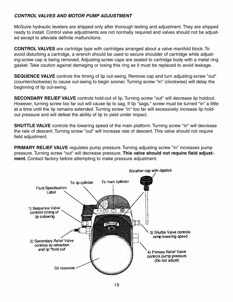
CONTROL VALVES AND MOTOR PUMP ADJUSTMENT
McGuire hydraulic levelers are shipped only after thorough testing and adjustment. They are shipped
ready to install. Control valve adjustments are not normally required and valves should not be adjust-
ed except to alleviate definite malfunctions.
CONTROL VALVES are cartridge type with cartridges arranged about a valve manifold block. To
avoid disturbing a cartridge, a wrench should be used to secure shoulder of cartridge while adjust-
ing-screw cap is being removed. Adjusting-screw caps are sealed to cartridge body with a metal ring
gasket. Take caution against damaging or losing this ring as it must be replaced to avoid leakage.
SEQUENCE VALVE controls the timing of lip out-swing. Remove cap and turn adjusting-screw "out"
(counterclockwise) to cause out-swing to begin sooner. Turning screw "in" (clockwise) will delay the
beginning of lip out-swing.
SECONDARY RELIEF VALVE controls hold-out of lip. Turning screw "out" will decrease lip holdout.
However, turning screw too far out will cause lip to sag. If lip "sags," screw must be turned "in" a little
at a time until the lip remains extended. Turning screw "in" too far will excessively increase lip hold-
out pressure and will defeat the ability of lip to yield under impact.
SHUTTLE VALVE controls the lowering speed of the main platform. Turning screw "in" will decrease
the rate of descent. Turning screw "out" will increase rate of descent. This valve should not require
field adjustment.
PRIMARY RELIEF VALVE regulates pump pressure. Turning adjusting screw "in" increases pump
pressure. Turning screw "out" will decrease pressure. This valve should not require field adjust-
ment. Contact factory before attempting to make pressure adjustment.
19
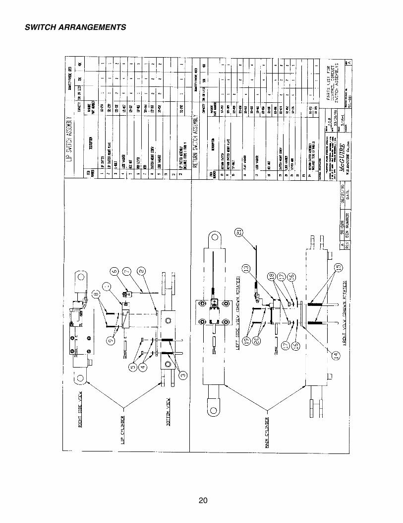
SWITCH ARRANGEMENTS
20
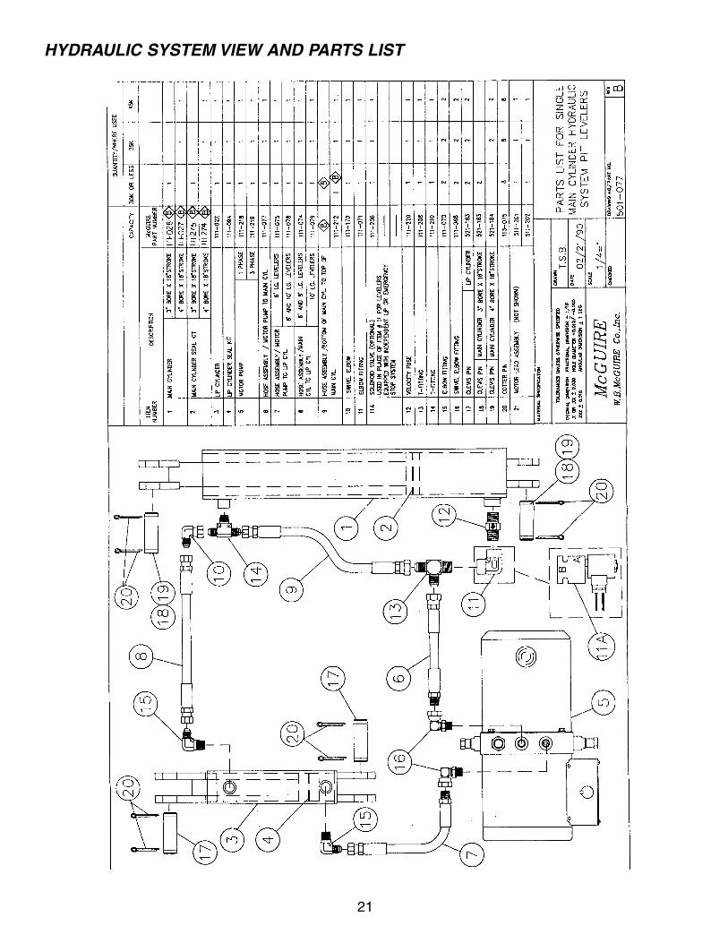
HYDRAULIC SYSTEM VIEW AND PARTS LIST
21
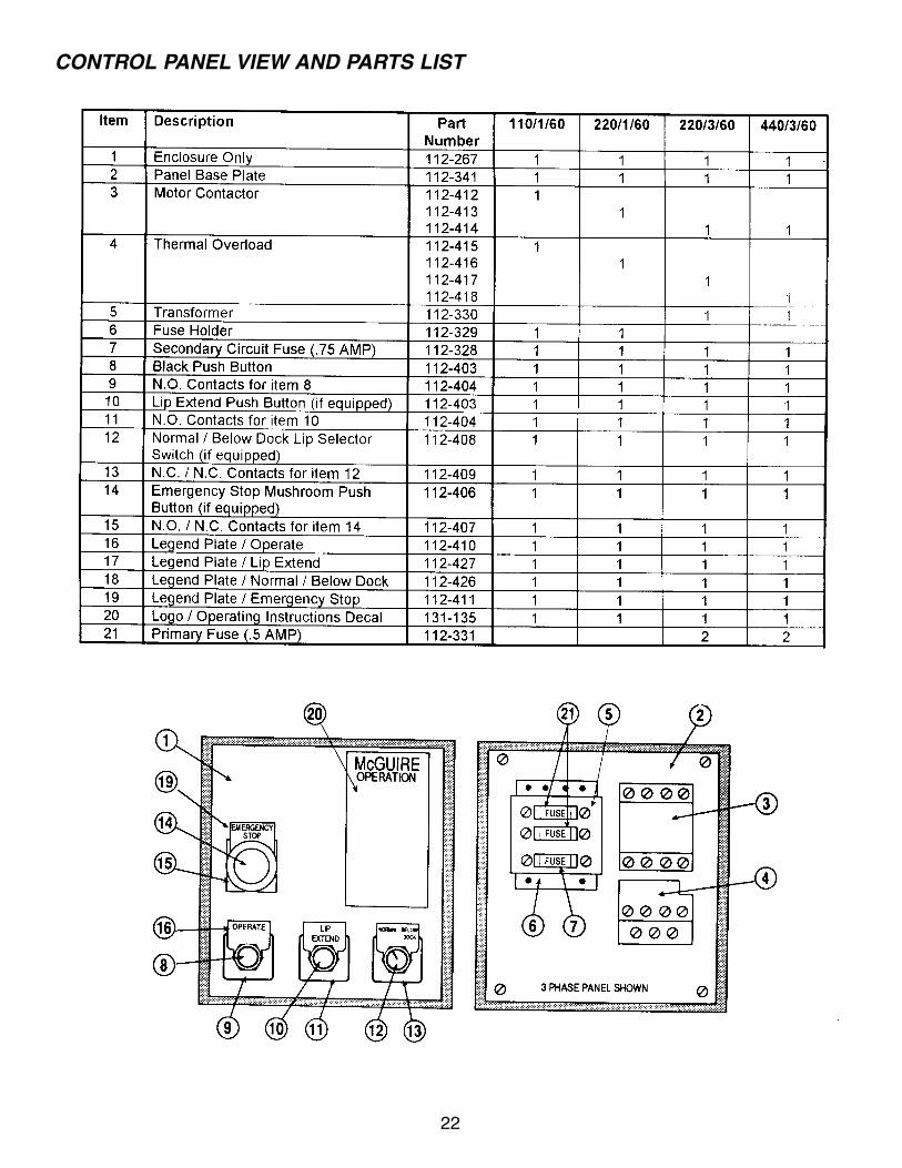
CONTROL PANEL VIEW AND PARTS LIST
22
W.B. McGUIRE COMPANY, INC.
Hydraulic Dock Leveler Warranty
The W.B. McGuire Company, Inc. warrants that its hydraulic dock leveler (see models below) will be
free from defects in materials and workmanship under normal use and service for the time period
described below, depending on model, effective from the date of installation. This warranty covers
parts and labor.
McGuire's sole obligation under this warranty is limited to repairing or replacing any part which shall
be determined by McGuire to be defective, and is conditioned upon the buyer giving written notice of
any such defect within the warranty period. If McGuire concludes that repair or replacement is nec-
essary, work will commence within a reasonable time period after the decision to repair or replace
has been made.
This warranty will not apply to any product which has been altered, modified, damaged or which has
deteriorated due to abuse, neglect, misuse or by accident. Warranty will be VOID if any repairs are
made or attempted to be made by any person not authorized by McGuire. Proper application, instal-
lation, maintenance and operation are required to keep warranty in force.
Hydraulic systems are factory preset. Periodic maintenance and adjustment is the sole responsibility
of the owner.
This warranty is McGuire's exclusive expressed warranty. Warranty is limited to value of components
only. McGuire assumes no liability for loss of the use of any equipment and expressly disclaims any
liability for incidental or consequential damages. Warranties implied by law are limited in duration to
the five year period described above.
HYDLEV/31-5-1 Go back to Main Page PRINTED IN U.S.A.
Models covered by this warranty:
M-Series (5 years)
MKA 1300 (1 year)
MKA 1000HD & MKA 1000LB (1 year)
One Hudson Ave.Hudson, NY 125341-800-624-8473518-828-7652 • Fax: 518-828-1262www.wbmcguire.com
The specifications described herein were in effect at the time of printing. However, W.B. McGuire Company, Inc. reserves the right to change specifications and designs or to discontinue models at any time without incurring obligation.
Represented in This Area By: