hydraulic cylinders j ic h e
TRANSCRIPT

HYDRAULIC CYLINDERS
■ Hydraulic Cylinders
Hydraulic cylinders are devices which convert fluids power into mechanical force or motion. This force or
motion will be in a straight line.
Graphic Symbol
■ “CE” Series Hydraulic Cylinders
CE-Type standard hydraulic cylinders (small bore series) have a variety of applications in various fields.
■ Specification
Cylinder
Model Number Bore mm
Surge Pressure
Kgf/cm2
Allowable Withstand
Operating
Pressure
Kgf/cm2
Max. Min.
Operating
Speed
mm/sec
Max. Min.
Max. Ambt.
Stroke Temp mm Range
0C
Stroke
Tolerance
CE-_ -__ -140B
40, 50
63, 80 100, 125,
150
210 (105)
*1
210 140 (105)
*1 (70)
*1
1200*
3 300*2
10 1600*
-10 ~ +80
200*3
Ref
Table-1
*1 In case of ‘LB’ type mounting, pressure will be as given in ( ).
*2 Surge Pressure should be kept within acceptable range. *3 Stroke should be determined according to buckling strength. Obtain the max. stroke
according to the buckling strength from the chart given in the page11.
■ Tolerance of Stroke
[Table 1]
Stroke
Tolerance
mm
mm
~ 100
+0.8
0
100 ~ 250
+1.0
0
250 ~ 630
+1.25
0
630 ~ 1000
+1.4
0
J
Hydraulic Cylinders
1
EIC
-J-1
00
1-0
H
ydra
uli
c C
yli
nd
ers

HYDRAULIC CYLINDERS
■ Model Number Designation
F- CE -LA -100 B -140 B -100 -30 80
Special Series
Series Number
Max. operating Mounting Rod Type Pressure
Kgf/cm2
Location of
Cushion
Stroke Design* Design
mm Number Std.
F: Applicable
CE:
Phosphate CE Type
Ester Type hydraulic
(Omit if not cylinder
required)
B:
Heavy
LA, LB 40, 50 Duty
FA, FB 63, 80 TA, TC 100, 125
CA 150 C:
Standard
Type
B:
With cushion
at both ends
R:
With cushion
at rod end 140 : 140
H:
With cushion
at head end
N: No cushion
provided
Ex: 100 mm
For different
stroke
length
requirement,
refer to
rating table
on page 3 to
10
30 80
* Design Numbers subjected to change from 30 to 39 but installation dimensions remain same.
■ Mounting
Name of Mounting
Type
Illustration of
Mounting type
Name of Mounting
Type
Illustration of
Mounting type
LA: Foot Mounting
Side Lugs
LB: Foot Mounting
Side End Angle
TA: Rod Trunnion
TC: Intermediate Trunnion
FA: Rod Rectangular CA: Cap detachable
Flange eye/clevis
FB: Cap/Head Rectangular
Flange
Care in Application
1 Air Bleeding : Air Bleed screws are provided at head and rod side to remove any air entrapped in the oil
chamber. Turn the screw anti-clockwise to remove air. After air removal turn the screw clockwise to close
the screw. 2 Cushion : Cylinder cushion are often provided at both ends of the cylinder to slow down near the end of the
stroke and prevent the piston from hammering against the end cap. 3 Cushion Adjust Valve : Turn the screw clockwise for longer cushioning time and turn screw anti-clockwise
for shorter cushion time.
Effective Length of Cushion
Cushion
Position
Cylinder Bore mm
40 50 63 80 100 125 150
Head Side mm
Rod Side mm
10 13 13 15 15 15 15
17 20 20 22 22 25 25
2 Hydraulic Cylinders
Cylinder Bore mm
for
Fluids
standard Type

L
L
CELA-40B
M18,P1.5
31.5
20
22.4
6
17
CELA-50B
M22,P1.5
35.5
26
28
8
23
CELA-63B
M26,P1.5
40
33
35.5
8
29
CELA-80B
M33,P1.5
47.5
42
45
10
38
CELA-100B
M42,P1.5
56
53
56
10
46
CELA-125B
M55,P2
67
68
71
12
58
HYDRAULIC CYLINDERS
■ L A : Foot Mounting Side Lugs Type
The positions of connecting port and cushion adjusting screw can not be altered. The position of air vent is indicated
in the illustration as the standard. However it is changeable to other position. When required to install the air vent at
any other position, please specify it by the following positional numbers ( II III & IV )
I 'F' Width
Across Flats R.SQ
'X' Dia. 'A' Thd.
4 Places IV II
Connecting Ports
'P' BSP.F Thd. 2 Places
H
Air Vent
2 Places
S + Stroke
N + Stroke
Cushion
Adj. Screw
2 Places
Q
2xPitch E Y K Z B G J M
T III Lo
BB Dia. knock pin hole
4 Places
U + Stroke
K
M
Calculate the approximate weight using the formula below.
Weight = Basic Weight + Added Weight Per Stroke of 100 mm x Stroke
Model Number
CELA-40C A B C D
M14,P1.5 28 16 18 E F G H J K L M N
6 14 30 45 20 20 11 29 94
P Q R S T
3/8 11 65 165 61
CELA-50C M18,P1.5 31.5 20 22.4 6 17
35.5 49.2 21.2 23 11.5 33.5 116 1/2 13 80 195.2 68.2
CELA-63C M22,P1.5 35.5 26 28 8 23
40 52 24 23 13.5 31.5 114 1/2 14 95 197 77.5
CELA-80C M26,P1.5 40 33 35.5 8 29
47.5 60.5 27 28 16.5 30.5 132 3/4 16 115 231 91
CELA-100C M33,P1.5 47.5 42 45 10 38
53 69 35.5 28 17 39 144 3/4 19 136 254.5 105.5
CELA-125C M42,P1.5 56 53 56 10 46
60 80 39 35.5 19.5 51.5 1658 1 21 165 299 118.5
CELA-150C
CELA-150B M50,P1.5 63 64 67 12 54
M65,P2 80 82 85 12 67
67 88.5 47.5 35.5 22.5 48.5 178 1 23 200 319.5 137
Weight (Approx.) Kg
Model Number U V W X Y Z AA BB Lo. Basic Added Weight Wt/100 mm
J
CELA-40C
CELA-40B
112 18
±0.15
33.5
90 112 64 5 89 4.6 0.9
92.5
4.7
1.0
CELA-50C
CELA-50B
138 21.2 4
±0.15 13 109 132 82.5 5
99.7 7.3 1.4
103.7
7.5
1.4
CELA-63C
CELA-63B
CELA-80C CELA-80B
132 25 5
±0.15 15 128
155 30 6
±0.25 18 152
155 97.5 5
185 117.5 8
113 11.3 2.0
117.5
11.6
2.3
131 20.0 3.0
138.5
20.5
3.5
CELA-100C
CELA-100B
CELA-125C CELA-125B
166 35.5 7
±0.25 20 178
200 42.5 8
±0.25 24 211
212 139 8
250 167.5 8
153 33.0 4.6
161.5
33.7
5.3
174.5 57.0 7.0
185.5
58.2
8.2
CELA-150C
CELB-150B
204 50
±0.25
103
255 300 203 8 200 89.0 10.3
217 90.5 11.8
Foot Mounting Side Lugs Type 3
11
28
V W
AA
Ce6
Dia
. D
Dia
.
Hydra
uli
c C
yli
nd
ers
100
2.5
0
0
1
5
CELB-40B
M18,P1.5
31.5
20
22.4
6
17
CELB-50B
M22,P1.5
33.5
26
28
8
23
CELB-63B
M26,P1.5
40
33
35.5
8
29
CELB-80B
M33,P1.5
47.5
42
45
10
38
CELB-100B
M42,P1.5
56
53
56
10
46
CELB-125B
M55,P2
67
68
71
12
58
33.5
4.6
1.0
36
7.3
1.6
43
11.1
2.3
53
19.7
3.5
59
31.7
5.3
67
56.8
8.2
HYDRAULIC CYLINDERS
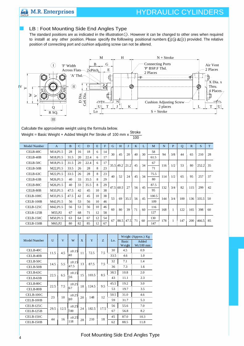
■ LB : Foot Mounting Side End Angles Type The standard positions are as indicated in the illustration I . However it can be changed to other ones when required
to install at any other position. Please specify the following positional numbers ( II III & IV ) provided. The relative
position of connecting port and cushion adjusting screw can not be altered.
M H N + Stroke
I 'F' Width
Across Flats
'A' Thd.
IV II
B G
2xPitch E
Connecting Ports
'P' BSP.F Thd. 2 Places
Air Vent
2 Places
X Dia. x
Thru. 4 Places
Q U T
R SQ. Lo
III
Z
J
Cushion Adjusting Screw
K 2 places L T
S + Stroke
U
Calculate the approximate weight using the formula below.
Weight = Basic Weight + Added Weight Per Stroke of 100 mm x Stroke
Model Number
CELB-40C A B C D
M14,P1.5 28 16 18 E F G H J K L
6 14 30 45 20 40 30
M
58
61.5
N P Q 94 3/8 44
R S T 65 210 28
CELB-50C M18,P1.5 31.5 20 22.4 6 17 35.5 49.2 21.2 45 34
67
71
116 1/2 53 80 252.2 35
CELB-63C M22,P1.5 33.5 26 28 8 23 40 52 24 45 34
75.5
80
114 1/2 65 95 257 37
CELB-80C M26,P1.5 40 33 35.5 8 29 47.5 60.5 27 56 45
87.5
95
132 3/4 82 115 299 42
CELB-100C
CELB-125C
M33,P1.5 47.5 42
M42,P1.5 56 53
45 10 38 53
56 10 46
60
69 35.5 56 45
80 39 71 60
100.5
109
116 127
144 3/4 100
168 1 122
136 335.5 50
165 398 60
CELB-150C
CELB-150B M50,P1.5
M65,P2 63 64 67 12 54
80 82 85 12 67
67 88.5 47.5 71 60 130
147
178 1 147 200 466.5 85
Weight (Approx.) Kg
Model Number U V W X Y Z Lo. Basic Added Weight Wt/100 mm
CELB-40C
CELB-40B
CELB-50C
CELB-50B
CELB-63C
CELB-63B
CELB-80C
CELB-80B
CELB-100C CELB-100B
11.5 4.5
14.5 5.5
22.5 6.5
22.5 7.5
23 10
4
±0.15 11
±0.15
47.5
5
±0.15 15
6
±0.25 18
8
±0.25 20
72.5 7.5 30 4.5 0.9
87.5 7.5 32 7.1 1.4
103.5 8.5 38.5 10.8 2.0
124.5 9.5 45.5 19.2 3.0
148 12 50.5 31.0 4.6
CELB-125C
CELB-125B 29.5 12.5
1
±0.25 24 182.5 17.5
56 55.6 7.0
CELB-150C
CELB-150B
44 16
±0.25
118
210 18 45 87.0 10.3
62 88.5 11.8
4 Foot Mounting Side End Angles Type
00
28
V
W
Ce6
Dia
. D
Dia
.
Y
100
0
13
6
7
0
CEFA-40B
M18, P1.5
31.5
20
22.4
6
17
CEFA-50B
M22, P1.5
35.5
26
28
8
23
CEFA-63B
M26, P1.5
40
33
35.5
8
29
CEFA-80B
M33, P1.5
47.5
42
45
10
38
CEFA-100B
M42, P1.5
56
53
56
10
46
CEFA-125B
M55, P2
67
68
71
12
58
61.5
4.3
1.0
71
6.9
1.6
80.0
10.3
2.3
95
18.3
3.5
109
28.9
5.3
127
51.7
8.2
HYDRAULIC CYLINDERS
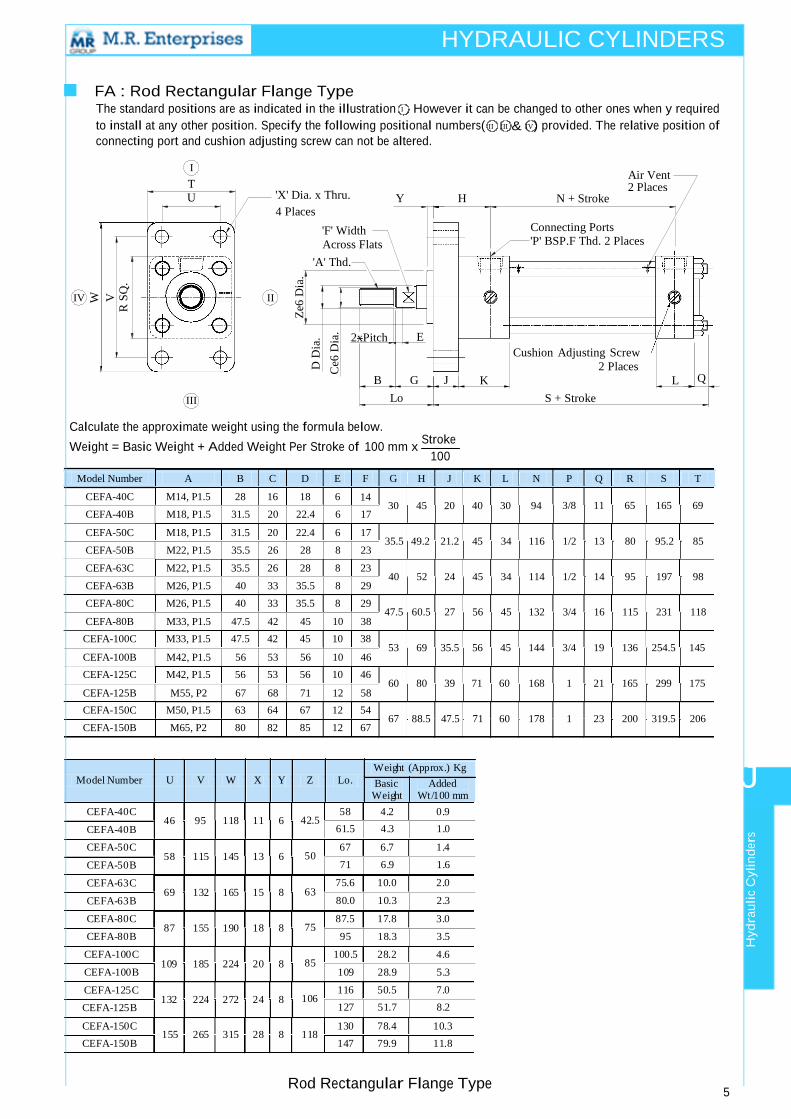
■ FA : Rod Rectangular Flange Type The standard positions are as indicated in the illustration I . However it can be changed to other ones when y required
to install at any other position. Specify the following positional numbers( II III & IV) provided. The relative position of
connecting port and cushion adjusting screw can not be altered.
I
T U 'X' Dia. x Thru. Y H
4 Places
Air Vent
2 Places N + Stroke
'F' Width
Across Flats
'A' Thd.
Connecting Ports 'P' BSP.F Thd. 2 Places
IV II
2xPitch E
B G J
III Lo
Cushion Adjusting Screw
2 Places K L
S + Stroke
Q
Calculate the approximate weight using the formula below.
Weight = Basic Weight + Added Weight Per Stroke of 100 mm x Stroke
Model Number
CEFA-40C A
M14, P1.5 B C D E
28 16 18 6 F G H J K L N
14 30 45 20 40 30 94
P Q R S T
3/8 11 65 165 69
CEFA-50C M18, P1.5 31.5 20 22.4 6 17
35.5 49.2 21.2 45 34 116 1/2 13 80 95.2 85
CEFA-63C M22, P1.5 35.5 26 28 8 23
40 52 24 45 34 114 1/2 14 95 197 98
CEFA-80C M26, P1.5 40 33 35.5 8 29
47.5 60.5 27 56 45 132 3/4 16 115 231 118
CEFA-100C
CEFA-125C
CEFA-150C
CEFA-150B
M33, P1.5 47.5 42 45 10 38
M42, P1.5 56 53 56 10 46
M50, P1.5 63 64 67 12 54
M65, P2 80 82 85 12 67
53 69 35.5 56 45 144
60 80 39 71 60 168
67 88.5 47.5 71 60 178
3/4 19 136
1 21 165
1 23 200
254.5 145
299 175
319.5 206
Weight (Approx.) Kg
Model Number U V W X Y Z Lo. Basic Added Weight Wt/100 mm
J
CEFA-40C
CEFA-40B
CEFA-50C
CEFA-50B
CEFA-63C
CEFA-63B
CEFA-80C
CEFA-80B
CEFA-100C
CEFA-100B
CEFA-125C CEFA-125B
46 95 118 11 6
58 115 145 13 6
69 132 165 15 8
87 155 190 18 8
109 185 224 20 8
132 224 272 24 8
42.5 58 4.2 0.9
50 67 6.7 1.4
63 75.6 10.0 2.0
75 87.5 17.8 3.0
85 100.5 28.2 4.6
106 116 50.5 7.0
CEFA-150C
CEFA-150B
155 265 315 28 8 118 130 78.4 10.3
147 79.9 11.8
Rod Rectangular Flange Type 5
Ce6
Dia
. D
Dia
.
Hydra
uli
c C
yli
nd
ers
W
V
R S
Q.
Ze6
Dia
.
100
CEFB-40B
M18, P1.5
31.5
20
22.4
6
17
CEFB-50B
M22, P1.5
35.5
26
28
8
23
CEFB-63B
M26, P1.5
40
33
35.5
8
29
CEFB-80B
M33, P1.5
47.5
42
45
10
38
CEFB-100B
M42, P1.5
56
53
56
10
46
CEFB-125B
M55, P2
67
68
71
12
58
235.5+Stroke
5.3
1.0
274.7+Stroke
8.6
1.6
287+Stroke
13.0
2.3
337+Stroke
22.7
3.5
380+Stroke
36.8
5.3
444+Stroke
64.4
8.2
HYDRAULIC CYLINDERS
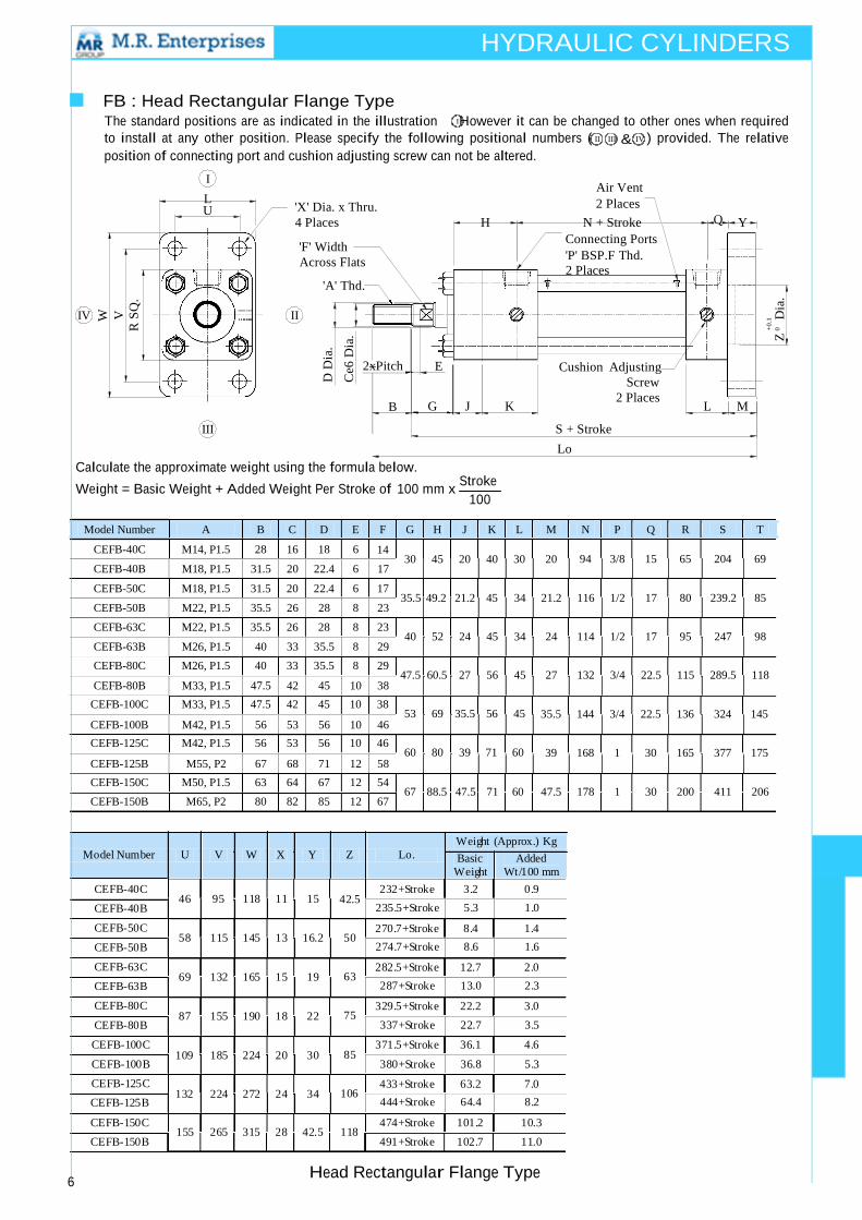
■ FB : Head Rectangular Flange Type The standard positions are as indicated in the illustration . However it can be changed to other ones when required
to install at any other position. Please specify the following positional numbers ( II III & IV ) provided. The relative
position of connecting port and cushion adjusting screw can not be altered.
I
L U 'X' Dia. x Thru.
4 Places
'F' Width
Across Flats
'A' Thd.
Air Vent
2 Places H N + Stroke Q Y
Connecting Ports 'P' BSP.F Thd.
2 Places
IV II
III
2xPitch
B
E Cushion Adjusting
Screw
G J K 2 Places
L M
S + Stroke
Lo
Calculate the approximate weight using the formula below.
Weight = Basic Weight + Added Weight Per Stroke of 100 mm x Stroke
Model Number
CEFB-40C A
M14, P1.5 B C D E
28 16 18 6 F G H J K L M
14 30 45 20 40 30 20
N P Q R S T 94 3/8 15 65 204 69
CEFB-50C M18, P1.5 31.5 20 22.4 6 17
35.5 49.2 21.2 45 34 21.2 116 1/2 17 80 239.2 85
CEFB-63C M22, P1.5 35.5 26 28 8 23
40 52 24 45 34 24 114 1/2 17 95 247 98
CEFB-80C M26, P1.5 40 33 35.5 8 29
47.5 60.5 27 56 45 27 132 3/4 22.5 115 289.5 118
CEFB-100C
CEFB-125C
M33, P1.5
M42, P1.5
47.5 42 45
56 53 56
10 38 53 69 35.5 56 45
10 46
60 80 39 71 60
35.5 144 3/4
39 168 1
22.5 136 324 145
30 165 377 175
CEFB-150C
CEFB-150B M50, P1.5
M65, P2 63 64 67 12 54
80 82 85 12 67
67 88.5 47.5 71 60 47.5 178 1 30 200 411 206
Weight (Approx.) Kg
Model Number U V W X Y Z Lo. Basic Added Weight Wt/100 mm
CEFB-40C
CEFB-40B
CEFB-50C
CEFB-50B
CEFB-63C
CEFB-63B
CEFB-80C
CEFB-80B
CEFB-100C
CEFB-100B
CEFB-125C CEFB-125B
46 95 118 11 15
58 115 145 13 16.2
69 132 165 15 19
87 155 190 18 22
109 185 224 20 30
132 224 272 24 34
42.5 232+Stroke 3.2 0.9
50 270.7+Stroke 8.4 1.4
63 282.5+Stroke 12.7 2.0
75 329.5+Stroke 22.2 3.0
85 371.5+Stroke 36.1 4.6
106 433+Stroke 63.2 7.0
CEFB-150C
CEFB-150B
155 265 315 28 42.5 118 474+Stroke 101.2 10.3
491+Stroke 102.7 11.0
6 Head Rectangular Flange Type
I
Ce6
Dia
.
D D
ia.
+0
.1
Z0
D
ia.
W
V
R S
Q.
100
X
.
U
M
Screw S + Stroke
Lo
CETA-40B
M18, P1.5
31.5
20
22.4
6
17
CETA-50B
M22, P1.5
35.5
26
28
8
23
CETA-63B
M26, P1.5
40
33
35.5
8
29
CETA-80B
M33, P1.5
47.5
42
45
10
38
CETA-100B
M42, P1.5
56
53
56
10
46
CETA-125B
M55, P2
67
68
71
12
58
HYDRAULIC CYLINDERS
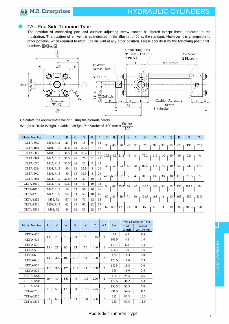
■ TA : Rod Side Trunnion Type The position of connecting port and cushion adjusting screw cannot be altered except those indicated in the
illustration. The position of air vent is as indicated in the illustration I as the standard. However it is changeable to
other position, when required to install the air vent at any other position. Please specify it by the following positional numbers ( II III & IV)
I
Z
-0.2
-0.3
Y
X
'F' Width
Across Flats
Connecting Ports
'P' BSP.F Thd. 2 Places
H
Air Vent
2 Places N + Stroke
'A' Thd.
IV II
Q
'R' SQ.
III
2xPitch E B G J K Cushion Adjusting L
Calculate the approximate weight using the formula below.
Weight = Basic Weight + Added Weight Per Stroke of 100 mm x Stroke
Model Number
CETA-40C A B C D
M14, P1.5 20 16 18 E F G H J K L M
6 14 30 45 20 40 30 70
N P Q R 94 3/8 10 65
S T 195 32.5
CETA-50C M18, P1.5 31.5 20 22.4 6 17
35.5 49.2 21.2 45 34 79.2 116 1/2 10 80 231 40
CETA-63C M22, P1.5 35.5 26 28 8 23
40 52 24 45 34 86.5 114 1/2 10 95 237 47.5
CETA-80C M26, P1.5 40 33 35.5 8 29
47.5 60.5 27 56 45 102.5 132 3/4 10 115 278.5 57.5
CETA-100C
CETA-125C
M33, P1.5 47.5 42
M42, P1.5 56 53
45 10 38 53
56 10 46
60
69 35.5 56 45 116.5 144
80 39 71 60 134.5 168
3/4 10 136
1 10 165
307.5 68
359 82.5
CETA-150C
CETA-150B M50, P1.5
M65, P2 63 64 67 12 54
80 82 85 12 67
67 88.5 47.5 71 60 150 178 1 10 200 386.5 100
Weight (Approx.) Kg
Model Number U V W X Y Z AA Lo. Basic Added Weight Wt/100 mm
J
CET A-40C
CET A-40B
CET A-50C
CET A-50B
CET A-63C
CET A-63B
CET A-80C
CET A-80B
CET A-100C
CET A-100B
CET A-125C CET A-125B
11 20 75
13 25 90
14 31.5 105
16 31.5 125
19 40 146
21 50 175
20 57.5 115 1
25 70 140 1
31.5 84 168 2
31.5 94 188 2
40 113 226 2
50 137.5 275 2
98 4.2 0.9
101.5
4.3
1.0
110.7 6.8 1.4
114..7
7.0
1.6
122 10.3 2.0
126.5
10.6
2.3
142.5 18.5 3.0
150
19.0
3.5
164 29.5 4.6
172.5
30.2
5.3
190.5 53.3 7.0
201.5
54.5
8.2
CET A-150C
CET A-150B
23 63 210 63 168 336 2 213 82.3 10.3
230 83.8 11.8
Rod Side Trunnion Type 7
Hydra
uli
c C
yli
nd
ers
W
Ve8
Dia
T
Ce6
Dia
. D
Dia
.
100
X
.
CETC-40B
M18, P1.5
31.5
20
22.4
6
17
CETC-50B
M22, P1.5
35.5
26
28
8
23
CETC-63B
M26, P1.5
40
33
35.5
8
29
CETC-80B
M33, P1.5
47.5
42
45
10
38
CETC-100B
M42, P1.5
56
53
56
10
46
CETC-125B
M55, P2
67
68
71
12
58
HYDRAULIC CYLINDERS
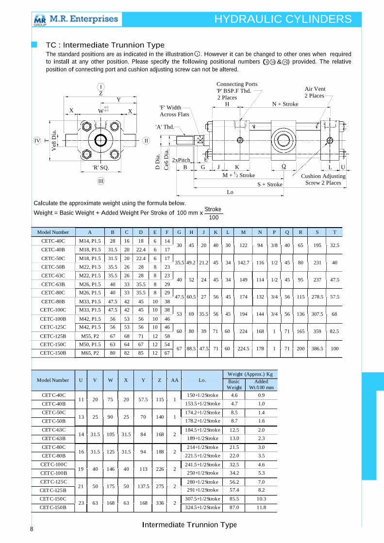
■ TC : Intermediate Trunnion Type The standard positions are as indicated in the illustration I . However it can be changed to other ones when required
to install at any other position. Please specify the following positional numbers ( II III & IV) provided. The relative
position of connecting port and cushion adjusting screw can not be altered.
I
Z Y
-0.2
-0.3
X
'F' Width
Across Flats 'A' Thd.
Connecting Ports
'P' BSP.F Thd. 2 Places
H
Air Vent
2 Places
N + Stroke
IV II
2xPitch
'R' SQ. B
III
E G J K Q
M +1
2 Stroke
S + Stroke
Lo
L U
Cushion Adjusting
Screw 2 Places
Calculate the approximate weight using the formula below.
Weight = Basic Weight + Added Weight Per Stroke of 100 mm x Stroke
Model Number
CETC-40C A B C D
M14, P1.5 28 16 18 E F G H J K L M
6 14 30 45 20 40 30 122
N P Q R 94 3/8 40 65
S T 195 32.5
CETC-50C M18, P1.5 31.5 20 22.4 6 17
35.5 49.2 21.2 45 34 142.7 116 1/2 45 80 231 40
CETC-63C M22, P1.5 35.5 26 28 8 23
40 52 24 45 34 149 114 1/2 45 95 237 47.5
CETC-80C M26, P1.5 40 33 35.5 8 29
47.5 60.5 27 56 45 174 132 3/4 56 115 278.5 57.5
CETC-100C
CETC-125C
M33, P1.5 47.5 42 45
M42, P1.5 56 53 56
10 38 53 69 35.5 56 45
10 46
60 80 39 71 60
194 144 3/4 56 136
224 168 1 71 165
307.5 68
359 82.5
CETC-150C
CETC-150B M50, P1.5
M65, P2 63 64 67 12 54
80 82 85 12 67
67 88.5 47.5 71 60 224.5 178 1 71 200 386.5 100
Weight (Approx.) Kg
Model Number U V W X Y Z AA Lo. Basic Added Weight Wt/100 mm
CETC-40C
CETC-40B
CETC-50C
CETC-50B
CETC-63C
CETC-63B
CETC-80C
CETC-80B
CETC-100C
CETC-100B
CETC-125C CETC-125B
11 20 75
13 25 90
14 31.5 105
16 31.5 125
19 40 146
21 50 175
20 57.5 115 1
25 70 140 1
31.5 84 168 2
31.5 94 188 2
40 113 226 2
50 137.5 275 2
150+1/2Stroke 4.6 0.9
153.5+1/2Stroke
4.7
1.0
174.2+1/2Stroke 8.5 1.4
178.2+1/2Stroke
8.7
1.6
184.5+1/2Stroke 12.5 2.0
189+1/2Stroke
13.0
2.3
214+1/2Stroke 21.5 3.0
221.5+1/2Stroke
22.0
3.5
241.5+1/2Stroke 32.5 4.6
250+1/2Stroke
34.2
5.3
280+1/2Stroke 56.2 7.0
291+1/2Stroke
57.4
8.2
CETC-150C
CETC-150B
23 63 168 63 168 336 2 307.5+1/2Stroke 85.5 10.3
324.5+1/2Stroke 87.0 11.8
8 Intermediate Trunnion Type
W
Ve8
Dia
T
Ce6
Dia
. D
Dia
.
100
CECA-40B
M18, P1.5
31.5
20
22.4
6
17
CECA-50B
M22, P1.5
35.5
26
28
8
23
CECA-63B
M26, P1.5
40
33
35.5
8
29
CECA-80B
M33, P1.5
47.5
42
45
10
38
CECA-100B
M42, P1.5
56
53
56
10
46
CECA-125B
M55, P2
67
68
71
12
58
HYDRAULIC CYLINDERS
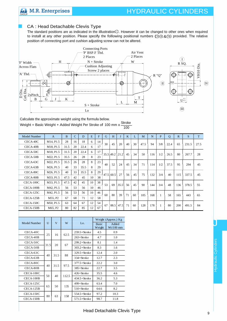
■ CA : Head Detachable Clevis Type The standard positions are as indicated in the illustration I . However it can be changed to other ones when required
to install at any other position. Please specify the following positional numbers ( II III & IV) provided. The relative
position of connecting port and cushion adjusting screw can not be altered.
'F' Width
Across Flats
'A' Thd.
Connecting Ports
'P' BSP.F Thd. 2 Places
H N + Stroke
Cushion Adjusting Screw 2 places
Air Vent
2 Places
W
R "Q"
I R SQ.
II IV
2xPitch E B G J K
T -0.1
S + Stroke L M
-0.3
Lo
III
Calculate the approximate weight using the formula below.
Weight = Basic Weight + Added Weight Per Stroke of 100 mm x Stroke
Model Number
CECA-40C A B C D
M14, P1.5 28 16 18 E F G H J K L M N
6 14 30 45 20 40 30 47.5 94
P Q R
3/8 22.4 65
S T 231.5 27.5
CECA-50C M18, P1.5 31.5 20 22.4 6 17
35.5 49.2 21.2 45 34 50 116 1/2 26.5 80 267.7 28
CECA-63C M22, P1.5 35.5 26 28 8 23
40 52 24 45 34 71 114 1/2 37.5 95 294 45
CECA-80C M26, P1.5 40 33 35.5 8 29
47.5 60.5 27 56 45 75 132 3/4 40 115 337.5 45
CECA-100C
CECA-125C
M33, P1.5 47.5 42 45
M42, P1.5 56 53 56
10 38 53 69 35.5 56 45
10 46
60 80 39 71 60
90 144 3/4
105 168 1
48 136 378.5 55
58 165 443 65
CECA-150C
CECA-150B M50, P1.5
M65, P2 63 64 67 12 54
80 82 85 12 67
67 88.5 47.5 71 60 128 178 1 80 200 491.5 84
Weight (Approx.) Kg
Model Number U V W Lo. Basic Added Weight Wt/100 mm
J
CECA-40C
CECA-40B
CECA-50C
CECA-50B
CECA-63C
CECA-63B
CECA-80C
CECA-80B
CECA-100C
CECA-100B
CECA-125C
CECA-125B
CECA-150C CECA-150B
25 16 62.5
31.5 20 67
40 31.5 88
40 31.5 97.5
50 40 112.5
63 50 135
80 63 158
259.5+Stroke 4.5 0.9
263+Stroke 4.7 1.0
299.2+Stroke 8.1 1.4
303.2+Stroke 8.3 1.6
329.5+Stroke 12.4 2.0
334+Stroke 12.7 2.3
377.5+Stroke 22.2 3.0
385+Stroke 22.7 3.5
426+Stroke 35.5 4.6
434.5+Stroke 36.2 5.3
499+Stroke 63.4 7.0
510+Stroke 64.6 8.2
554.5+Stroke 97.2 10.3 571.5+Stroke 98.7 11.8
Head Detachable Clevis Type 9
Hydra
uli
c C
yli
nd
ers
Ce6
Dia
. D
Dia
.
VH
10 D
ia.
U
100
HYDRAULIC CYLINDERS
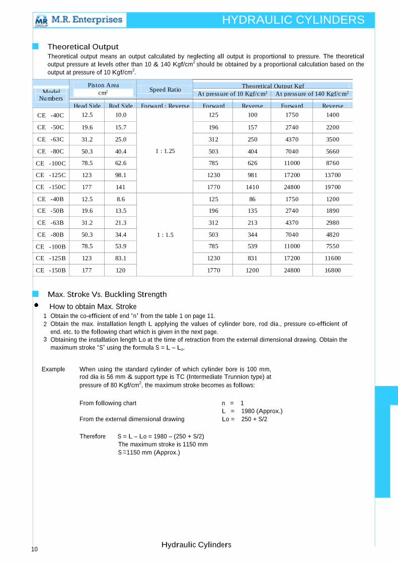
■ Theoretical Output Theoretical output means an output calculated by neglecting all output is proportional to pressure. The theoretical
output pressure at levels other than 10 & 140 Kgf/cm2
should be obtained by a proportional calculation based on the
output at pressure of 10 Kgf/cm2.
Piston Area
Theoretical Output Kgf
Speed Ratio
Model
cm
At pressure of 10 Kgf/cm
At pressure of 140 Kgf/cm
Nu mbers
Head Side
Rod Side
Forward : Reverse
Forward
Reverse
Forward
Reverse
CE_ -40C
12.5
10.0
1 : 1.25
125
100
1750
1400
CE_ -50C
19.6
15.7
196
157
2740
2200
CE_ -63C
31.2
25.0
312
250
4370
3500
CE_ -80C
50.3
40.4
503
404
7040
5660
CE_ -100C
78.5
62.6
785
626
11000
8760
CE_ -125C
123
98.1
1230
981
17200
13700
CE_ -150C
177
141
1770
1410
24800
19700
CE_ -40B
12.5
8.6
1 : 1.5
125
86
1750
1200 CE_ -50B
19.6
13.5
196
135
2740
1890
CE_ -63B
31.2
21.3
312
213
4370
2980
CE_ -80B
50.3
34.4
503
344
7040
4820
CE_ -100B
78.5
53.9
785
539
11000
7550
CE_ -125B
123
83.1
1230
831
17200
11600
CE_ -150B
177
120
1770
1200
24800
16800
■ Max. Stroke Vs. Buckling Strength
How to obtain Max. Stroke 1 Obtain the co-efficient of end ‘n’ from the table 1 on page 11.
2 Obtain the max. installation length L applying the values of cylinder bore, rod dia., pressure co-efficient of
end. etc. to the following chart which is given in the next page. 3 Obtaining the installation length Lo at the time of retraction from the external dimensional drawing. Obtain the
maximum stroke ‘S’ using the formula S = L – Lo.
Example When using the standard cylinder of which cylinder bore is 100 mm,
rod dia is 56 mm & support type is TC (Intermediate Trunnion type) at
pressure of 80 Kgf/cm2, the maximum stroke becomes as follows:
From following chart n = 1
L = 1980 (Approx.)
From the external dimensional drawing Lo = 250 + S/2
Therefore S = L – Lo = 1980 – (250 + S/2)
The maximum stroke is 1150 mm
S ~1150 mm (Approx.)
10 Hydraulic Cylinders
2 2 2
~

HYDRAULIC CYLINDERS
■ Max. Installation Length Vs. Cylinder Bore.
30000
20000
10000
5000
2000
1000
500
500
400
315
250
200
160 125 106 90 80 67
45
28 18
450
355
280
224
180
140 112 100 85 71 56 35.5 22.4
n = 14
n = 1
n = 2
n = 4
200
100 0.3 0.5 1 2 5 10 20 50 100 200 500 800 x 10³
10 Load (Approx.) Kgf
50
70
100
140
Cylinder Bore mm
Table - 1
Sup-port
Type
Operating
Condition
Coef-
ficient
of End n
Sup-port
Type
Operating
Condition
Coef-
ficient
of End n
S Lo
14
LA- L
Type
S Lo 2
LB- L Type
S Lo 4
L
S
FB- Type S
S
Lo
14
L
Lo 2
J L
Lo 4
L S = L – Lo S = Stroke mm
S Lo
L
FA- Type S Lo
L
TA- 1
4
Type
2
TA- Type S Lo
L TC- Type S Lo
L
L = Installation Length at a time of
Expansion Lo = installation Length at a time of
Retraction 1 L & Lo = mm
Note: Obtain Lo from the
externational dimensional drawing
4 S Lo
L
CA- Type S Lo
L Hydraulic Cylinders
11
Hydra
uli
c C
yli
nd
ers
Ro
d D
ia.
mm
Pre
ssu
re K
gf/
cm
²
Max
. In
stall
ati
on
mm
L
en
gth
40
50
63
80
10
0
12
5
14
0
15
0
16
0
18
0
20
0
22
4
25
6
28
0
31
5
35
5
40
0
45
0
50
0
56
0
63
0
71
0
80
0

M.R. Enterprises 2013
Gat No. - 163, Triveni Nagar, Behind Nutan School, Talawade Road, Pune - 412114, Maharashtra
Tel: +91 020 64150629
e-mail: [email protected]
Standard
Hydraulic
Cylinder
range

WELCOME / CONTENTS Catalogue Contents
Welcome to the M.R. Enterprises standard range of hydraulic cylinders.
This catalogue is designed to give a snapshot of the hydraulic cylinder range
available from M.R. Enterprises. It’s purpose is to give an idea of standard cylinder
dimensions & mounting options for the information of Original
Equipment Manufacturers, machinery designers & hydraulic equipment users
in general.
WELCOME & CATALOGUE CONTENTS page 1 - 2
WELDED SPHERICAL BEARING MOUNTED CYLINDERS page 2 - 3
THREADED SPHERICAL BEARING MOUNTED CYLINDERS page 3 - 4
FRONT FLANGE MOUNTED CYLINDERS page 4 - 5
M.R. specialising
Enterprises are bespoke hydraulic cylinder manufacturers REAR CLEVIS MOUNTED CYLINDERS page 5 - 6 in fast delivery, cost-effective hydraulic cylinder solutions in
quantities from one-off to batch work. We produce cylinders from 25mm to
250mm bore, with a huge range of mounting options as standard, and the
engineering capability to produce any cylinder configuration to suit the needs
of the client. We can design for you, or work to your drawings and specifications.
REAR PIN MOUNTED CYLINDERS page 6 - 7
FORKED CLEVIS MOUNTED CYLINDERS page 7 - 8
ALTERNATIVE MOUNTINGS & HYDRAULIC CYLINDER FORCES TABLE page 8 - 9 Our standard range of cylinders has a working pressure of 210 bar. Also available
is our Heavy Duty range, rated to work at 350 bar, designed to operate in the
most arduous of conditions.
Cylinders can be fitted with a range of electronic position sensing devices, from
simple proximity sensors signalling extremities of stroke, to internally fitted
infinite resolution linear transducers with a variety of output options.
Please feel free to download this catalogue and incorporate our cylinder designs
into your machinery. If you do not see exactly what you are looking for please
do not hesitate to contact us, our design team are always on hand to assist you
in any way possible
Download
M.R. Enterprises
Gat No. - 163, Triveni Nagar, Behind Nutan School, Talawade Road, Pune - 412114, Maharashtra, India
Tel: +91 020 64150629
Email:
mrenterprisespune26@gmail
.com Scan the code above
Questions ?
If you would l ike more information, technical assistance or to place an order please,
Call us on +91 020 64150629
or e-mail [email protected]
Any

WELDED SPHERICAL BEARING MOUNTED CYLINDERS Cylinder Dimensions
A range of cylinders mounted on self-aligning spherical bearings, welded Bore DIA Rod DIA A B C D E F G H I J K
to the rear of the cylinder body and rod-end. Suitable for cylinders with
Carbon Steel rod material. 40
20
25
206 22 38 19 38 50 1/4”BSP 28 20 19 40
25
50 30 230 22 45 23 45 60 3/8”BSP 28 25 23 43
35
A + Stroke
E H Ref
30
60 35 261 22 51 28 51 70 3/8”BSP 32 30 28 50
K B C 40
Feed ports G 30
63 35 261 22 51 28 51 73 3/8”BSP 32 30 28 50
40
35
ØI ØI 70 40 259 25 51 28 51 80 3/8”BSP 32 30 28 50
50
ØF
80
Our bespoke cylinders are designed with Solidworks and AutoCad, all cylinders supplied fully tested. 100
J Certificates available upon request
D
40
50
60
40
50
60 70
302 25 61
351 28 69
30 61 95
35 69 115
1/2”BSP 35 35 30 60
1/2”BSP 35 40 35 82
Maximum working pressure 210 bar.
Test pressure 300 bar unless otherwise stated.
All cylinders can be used as Double Acting OR Single Acting pull / Single Acting push. Cylinders can
be supplied with sintered bronze breathers fitted to ports for single acting applications.
Cylinder material: ST52.3 DOM and CDS tube DIN2393 I.S.O. H8 & H9
Rod material: Standard Grade EN8 DIN UNI CK45, Hard Chrome Plated, minimum 25 microns
Alternative rod materials available: Chrome plated Stainless Steel grades 431S29T / 316 / 304;
NIKROM 350
Headbush material: Cast Iron - UNI5007–G25 unless otherwise stated
Bore diameters available from 25mm to 250mm.
350 bar Heavy Duty range of cylinders and alternative rod and bore combinations available
Data given illustrates standard sizes. Bespoke manufacturing options are always available, call or
Download email for further details.
All data is given in good faith but without responsibility and may be subject to change without notice, all dimensions in mm
M.R. Enterprises
Gat No. - 163, Triveni Nagar, Behind Nutan School, Talawade Road, Pune - 412114, Maharashtra, India
Tel: +91 020 64150629
Email:
mrenterprisespune26@gmail
.com Scan the code above
Questions ?
If you would l ike more information, technical assistance
or to place an order please,
Call us on +91 020 64150629
or e-mail [email protected]
Any
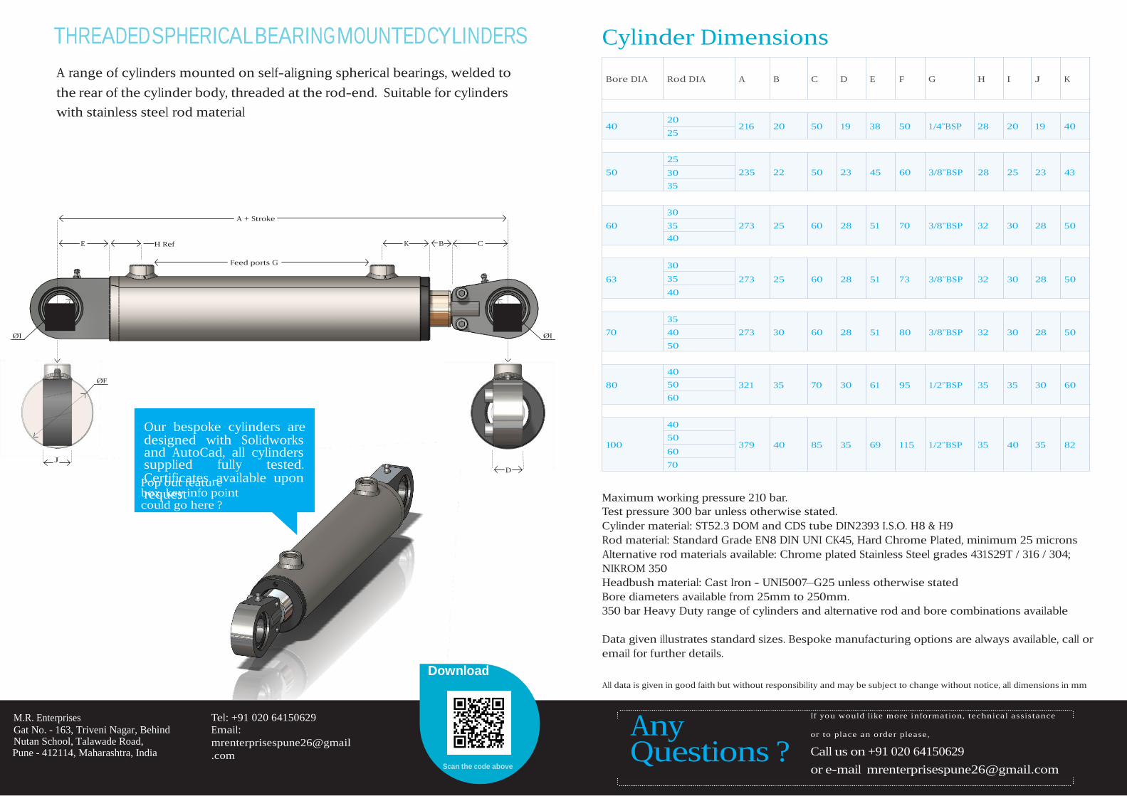
THREADED SPHERICAL BEARING MOUNTED CYLINDERS Cylinder Dimensions
A range of cylinders mounted on self-aligning spherical bearings, welded to
the rear of the cylinder body, threaded at the rod-end. Suitable for cylinders
with stainless steel rod material
Bore DIA
40
Rod DIA
20
25
A B C D
216 20 50 19
E F G H I J K
38 50 1/4”BSP 28 20 19 40
25
50 30 235 22 50 23 45 60 3/8”BSP 28 25 23 43
35
A + Stroke
E H Ref
30
60 35 273 25 60 28 51 70 3/8”BSP 32 30 28 50
K B C 40
Feed ports G 30
63 35 273 25 60 28 51 73 3/8”BSP 32 30 28 50
40
35
ØI ØI 70 40 273 30 60 28 51 80 3/8”BSP 32 30 28 50
50
40
ØF 80 50 321 35 70 30 61 95 1/2”BSP 35 35 30 60
60
Our bespoke cylinders are designed with Solidworks and AutoCad, all cylinders
J supplied fully tested. Certificates ravailable upon box, key info point could go here ?
40
100 60
379 40 85 35 69 115 1/2”BSP 35 40 35 82
D 70
Maximum working pressure 210 bar.
Test pressure 300 bar unless otherwise stated.
Cylinder material: ST52.3 DOM and CDS tube DIN2393 I.S.O. H8 & H9
Rod material: Standard Grade EN8 DIN UNI CK45, Hard Chrome Plated, minimum 25 microns
Alternative rod materials available: Chrome plated Stainless Steel grades 431S29T / 316 / 304;
NIKROM 350
Headbush material: Cast Iron - UNI5007–G25 unless otherwise stated
Bore diameters available from 25mm to 250mm.
350 bar Heavy Duty range of cylinders and alternative rod and bore combinations available
Data given illustrates standard sizes. Bespoke manufacturing options are always available, call or
email for further details.
Download All data is given in good faith but without responsibility and may be subject to change without notice, all dimensions in mm
M.R. Enterprises
Gat No. - 163, Triveni Nagar, Behind Nutan School, Talawade Road, Pune - 412114, Maharashtra, India
Tel: +91 020 64150629
Email:
mrenterprisespune26@gmail
.com Scan the code above
Questions ?
If you would l ike more information, technical assistance
or to place an order please,
Call us on +91 020 64150629
or e-mail [email protected]
request Pop out featu e
50
Any

FRONT FLANGE MOUNTED CYLINDERS Cylinder Dimensions
A range of cylinders mounted on a circular front flange, with a male threaded Bore DIA Rod DIA A B C D E F G H I J K
rod-end.
40
50
20
25
25
30
35
108 25 25
25
118 30 30
M16X1.5 109 50 M16X1.5
M20X1.5 128 60
1/4”BSP 11
3/8”BSP 13
87 12.5 40
105 14.5 43
A + Stroke
K
30
60 35 137 30 PCD I 40
30 M20X1.5
35 M24X2.0 142 70 3/8”BSP 13 117 16.5 50
40 M27X2.0
J B C
Feed ports G Thread D
30
63 35 137 30
40
30 M20X1.5
35 M24X2.0 142 73 3/8”BSP 13 117 16.5 50
40 M27X2.0
ØF
ØE 70
ØH
35
40 143 35
50
30 M24X2.0
40 M27X2.0 162 80 3/8”BSP 15 127 16.5 50
40
Front Flange 40 - 70 bore 4 holes ØH on PCD I 80 50
Front Flange 80 - 100 bore 6 holes ØH on PCD I 60
163 35 40
45
M27X2.0 181 95 1/2”BSP 17 149 18.5 60
M33X2.0
Our bespoke cylinders are designed with Solidworks and AutoCad, all cylinders supplied fully tested. Certificates x availablep upon request could go here ?
40 187 40
40 M27X2.0
100 45 M33X2.0 194 115 1/2”BSP 17 162 24.5 82
70 192 50
50 M39X2.0
Maximum working pressure 210 bar.
Test pressure 300 bar unless otherwise stated.
Cylinder material: ST52.3 DOM and CDS tube DIN2393 I.S.O. H8 & H9
Rod material: Standard Grade EN8 DIN UNI CK45, Hard Chrome Plated, minimum 25 microns
Alternative rod materials available: Chrome plated Stainless Steel grades 431S29T / 316 / 304;
NIKROM 350
Headbush material: Cast Iron - UNI5007–G25 unless otherwise stated
Bore diameters available from 25mm to 250mm.
350 bar Heavy Duty range of cylinders and alternative rod and bore combinations available
Data given illustrates standard sizes. Bespoke manufacturing options are always available, call or
email for further details.
Download All data is given in good faith but without responsibility and may be subject to change without notice, all dimensions in mm
M.R. Enterprises
Gat No. - 163, Triveni Nagar, Behind Nutan School, Talawade Road, Pune - 412114, Maharashtra, India
Tel: +91 020 64150629
Email:
mrenterprisespune26@gmail
.com Scan the code above
Questions ?
If you would l ike more information, technical assistance or to place an order please,
Call us on +91 020 64150629
or e-mail [email protected]
50
Pop out feature bo , key info oint
60
Any
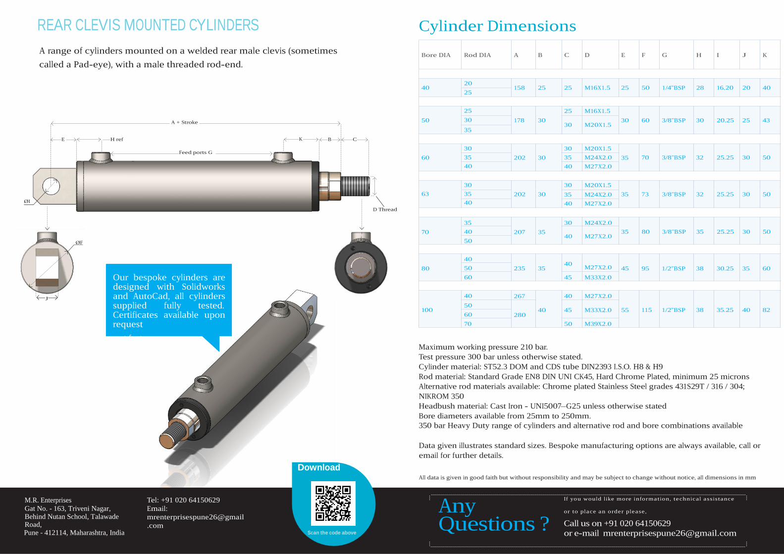
REAR CLEVIS MOUNTED CYLINDERS Cylinder Dimensions
A range of cylinders mounted on a welded rear male clevis (sometimes Bore DIA Rod DIA A B C D E F G H I J K
called a Pad-eye), with a male threaded rod-end.
40 20
25
158 25 25 M16X1.5 25 50 1/4”BSP 28 16.20 20 40
A + Stroke
E H ref
Feed ports G
25
50 30 178 30
35 K B C
30
60 35 202 30
40
25 M16X1.5
30 M20X1.5 30
30 M20X1.5
35 M24X2.0 35
40 M27X2.0
60 3/8”BSP 30 70 3/8”BSP 32
20.25 25 43 25.25 30 50
30
63 35 ØI 40
D Thread
30
202 30 35 40
M20X1.5
M24X2.0 35 73 3/8”BSP 32 25.25 30 50
M27X2.0
35
70 40 207 35
ØF 50
30 M24X2.0
40 M27X2.0 35 80 3/8”BSP 35 25.25 30 50
J
Our bespoke cylinders are designed with Solidworks and AutoCad, all cylinders supplied fully tested. Certificates available upon request
80
100
40
50 235
60
40 267
50 60 280
70
35 40
M27X2.0 45
45 M33X2.0
40 M27X2.0 40 45 M33X2.0 55
50 M39X2.0
95 1/2”BSP 38
115 1/2”BSP 38
30.25 35 60
35.25 40 82
Pop out feature box, key info point could go here ?
Maximum working pressure 210 bar.
Test pressure 300 bar unless otherwise stated.
Cylinder material: ST52.3 DOM and CDS tube DIN2393 I.S.O. H8 & H9
Rod material: Standard Grade EN8 DIN UNI CK45, Hard Chrome Plated, minimum 25 microns
Alternative rod materials available: Chrome plated Stainless Steel grades 431S29T / 316 / 304;
NIKROM 350
Headbush material: Cast Iron - UNI5007–G25 unless otherwise stated
Bore diameters available from 25mm to 250mm.
350 bar Heavy Duty range of cylinders and alternative rod and bore combinations available
Data given illustrates standard sizes. Bespoke manufacturing options are always available, call or
email for further details.
Download All data is given in good faith but without responsibility and may be subject to change without notice, all dimensions in mm
M.R. Enterprises
Gat No. - 163, Triveni Nagar, Behind Nutan School, Talawade Road, Pune - 412114, Maharashtra, India
Tel: +91 020 64150629
Email:
mrenterprisespune26@gmail
.com Scan the code above
Questions ?
If you would l ike more information, technical assistance or to place an order please,
Call us on +91 020 64150629
or e-mail [email protected]
Any
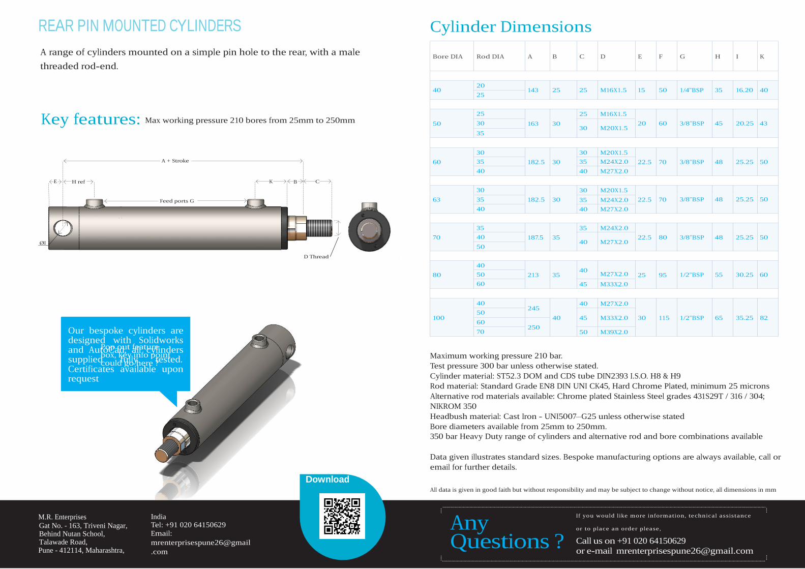
REAR PIN MOUNTED CYLINDERS Cylinder Dimensions
A range of cylinders mounted on a simple pin hole to the rear, with a male Bore DIA Rod DIA A B C D E F G H I K
threaded rod-end.
40 20
25
143 25 25 M16X1.5 15 50 1/4”BSP 35 16.20 40
Key features: Max working pressure 210 bores from 25mm to 250mm 50
25
30 163 30
35
25 M16X1.5
30 M20X1.5 20 60 3/8”BSP 45 20.25 43
E
H ref
A + Stroke
K B C
Feed ports G
30
60 35 182.5 30
40
30
63 35 182.5 30
40
30 M20X1.5
35 M24X2.0 22.5 70
40 M27X2.0
30 M20X1.5
35 M24X2.0 22.5 70
40 M27X2.0
3/8”BSP 48 3/8”BSP 48
25.25 50 25.25 50
ØI
D Thread
35
70 40 187.5 35
50
40
80 50 213 35
60
35 M24X2.0
40 M27X2.0 22.5 80
40 M27X2.0 25 95
45 M33X2.0
3/8”BSP 48 1/2”BSP 55
25.25 50 30.25 60
Our bespoke cylinders are designed with Solidworks and AutoCad, all cylinders supplied fully tested. Certificates available upon request
40 245
40 M27X2.0
100 40 45 M33X2.0 30 115 1/2”BSP 65 35.25 82
70 250
50 M39X2.0
Maximum working pressure 210 bar.
Test pressure 300 bar unless otherwise stated.
Cylinder material: ST52.3 DOM and CDS tube DIN2393 I.S.O. H8 & H9
Rod material: Standard Grade EN8 DIN UNI CK45, Hard Chrome Plated, minimum 25 microns
Alternative rod materials available: Chrome plated Stainless Steel grades 431S29T / 316 / 304;
NIKROM 350
Headbush material: Cast Iron - UNI5007–G25 unless otherwise stated
Bore diameters available from 25mm to 250mm.
350 bar Heavy Duty range of cylinders and alternative rod and bore combinations available
Data given illustrates standard sizes. Bespoke manufacturing options are always available, call or
email for further details.
Download All data is given in good faith but without responsibility and may be subject to change without notice, all dimensions in mm
M.R. Enterprises
Gat No. - 163, Triveni Nagar, Behind Nutan School, Talawade Road, Pune - 412114, Maharashtra,
India Tel: +91 020 64150629
Email:
mrenterprisespune26@gmail
.com
Questions ?
If you would l ike more information, technical assistance or to place an order please,
Call us on +91 020 64150629
or e-mail [email protected]
50
Pop out feature box, key info point could go here ?
60
Any
H Ref
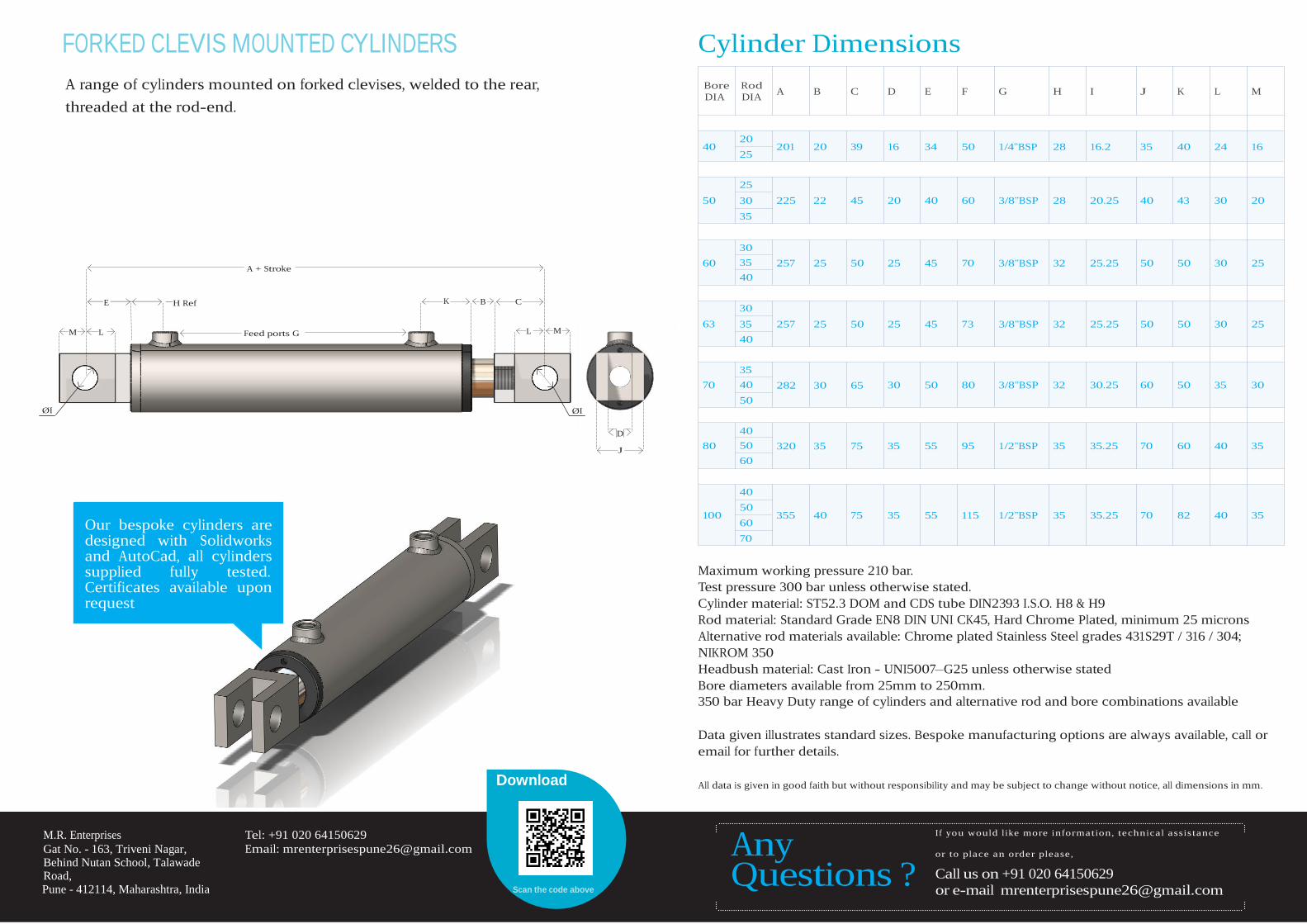
FORKED CLEVIS MOUNTED CYLINDERS Cylinder Dimensions
A range of cylinders mounted on forked clevises, welded to the rear,
threaded at the rod-end.
Bore Rod
DIA DIA
A B C D E F G H I J K L M
40
50
20
25
25
30
35
201 20 39
225 22 45
16 34 50 1/4”BSP 28
20 40 60 3/8”BSP 28
16.2 35 40 24 16
20.25 40 43 30 20
A + Stroke
30
60 35 257 25 50 25 45 70 3/8”BSP 32 25.25 50 50 30 25
40
E
K B C 30
M L Feed ports G L M 63 35 257 25 50 25 45 73 3/8”BSP 32 25.25 50 50 30 25
40
70
ØI ØI
D
J 80
35
40 282 30 65
50
40
50 320 35 75
60
30 50 80 3/8”BSP 32 35 55 95 1/2”BSP 35
30.25 60 50 35 30 35.25 70 60 40 35
Our bespoke cylinders are designed with Solidworks and AutoCad, all cylinders supplied fully tested. Certificates available upon request
40 100
60 355 40 75 35 55 115 1/2”BSP 35 35.25 70 82 40 35
70
Maximum working pressure 210 bar.
Test pressure 300 bar unless otherwise stated.
Cylinder material: ST52.3 DOM and CDS tube DIN2393 I.S.O. H8 & H9
Rod material: Standard Grade EN8 DIN UNI CK45, Hard Chrome Plated, minimum 25 microns
Alternative rod materials available: Chrome plated Stainless Steel grades 431S29T / 316 / 304;
NIKROM 350
Headbush material: Cast Iron - UNI5007–G25 unless otherwise stated
Bore diameters available from 25mm to 250mm.
350 bar Heavy Duty range of cylinders and alternative rod and bore combinations available
Data given illustrates standard sizes. Bespoke manufacturing options are always available, call or
email for further details.
Download All data is given in good faith but without responsibility and may be subject to change without notice, all dimensions in mm.
M.R. Enterprises
Gat No. - 163, Triveni Nagar, Behind Nutan School, Talawade Road, Pune - 412114, Maharashtra, India
Tel: +91 020 64150629
Email: [email protected]
Scan the code above
Questions ?
If you would l ike more information, technical assistance or to place an order please,
Call us on +91 020 64150629
or e-mail [email protected]
50
Any
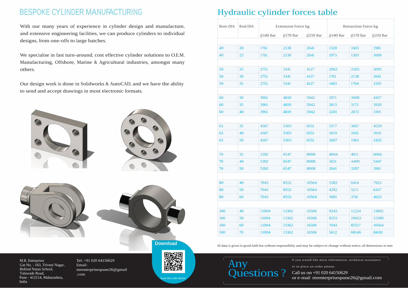
BESPOKE CYLINDER MANUFACTURING
With our many years of experience in cylinder design and manufacture,
and extensive engineering facilities, we can produce cylinders to individual
designs, from one-offs to large batches.
We specialise in fast turn-around, cost effective cylinder solutions to O.E.M.
Manufacturing, Offshore, Marine & Agricultural industries, amongst many
others.
Our design work is done in Solidworks & AutoCAD, and we have the ability
to send and accept drawings in most electronic formats.
Download
Hydraulic cylinder forces table
Bore DIA
Rod DIA
Extension Force kg
@140 Bar @170 Bar @210 Bar
Retraction Force kg
@140 Bar @170 Bar @210 Bar
40
20
1761
2138
2641
1320
1603
1981
40
25
1761
2138
2641
1073
1303
1609
50
25
2751
3341
4127
2063
2505
3095
50
30
2751
3341
4127
1761
2138
2641
50
35
2751
3341
4127
1403
1704
2105
60
30
3961
4810
5942
2971
3608
4457
60
35
3961
4810
5942
2613
3173
3920
60
40
3961
4810
5942
2201
2672
3301
63
35
4367
5303
6551
3377
3667
4529
63
40
4367
5303
6551
3019
3165
3910
63
50
4367
5303
6551
2607
1963
2425
70
35
5392
6547
8008
4044
4911
6066
70
40
5392
6547
8008
3631
4409
5447
70
50
5392
6547
8008
2641
3207
3961
80
40
7043
8552
10564
5282
6414
7923
80
50
7043
8552
10564
4292
5211
6437
80
60
7043
8552
10564
3081
3741
4622
100
40
11004
13362
16506
9243
11224
13865
100
50
11004
13362
16506
8253
10022
12380
100
60
11004
13362
16506
7043
85517
10564
100
70
11004
13362
16506
5612
68146
84181
All data is given in good faith but without responsibility and may be subject to change without notice, all dimensions in mm
M.R. Enterprises
Gat No. - 163, Triveni Nagar, Behind Nutan School, Talawade Road, Pune - 412114, Maharashtra, India
Tel: +91 020 64150629
Email:
mrenterprisespune26@gmail
.com Scan the code above
Questions ?
If you would l ike more information, technical assistance or to place an order please,
Call us on +91 020 64150629
or e-mail [email protected]
Any
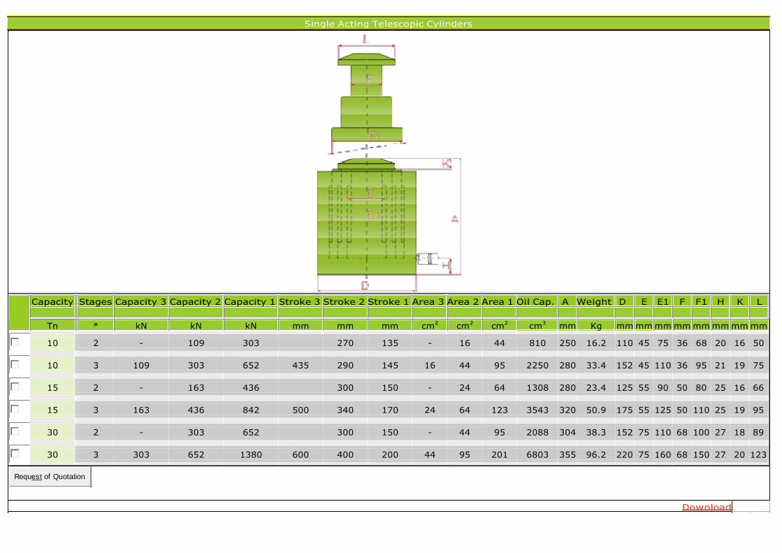
Single Acting Telescopic Cylinders
Capacity Stages Capacity 3 Capacity 2 Capacity 1 Stroke 3 Stroke 2 Stroke 1 Area 3 Area 2 Area 1 Oil Cap. A Weight D E E1 F F1 H K L
Tn * kN kN kN mm mm mm cm2
cm2
cm2
cm3
mm Kg mm mm mm mm mm mm mm mm
10 2 - 109 303 270 135 - 16 44 810 250 16.2 110 45 75 36 68 20 16 50
10 3 109 303 652 435 290 145 16 44 95 2250 280 33.4 152 45 110 36 95 21 19 75
15 2 - 163 436 300 150 - 24 64 1308 280 23.4 125 55 90 50 80 25 16 66
15 3 163 436 842 500 340 170 24 64 123 3543 320 50.9 175 55 125 50 110 25 19 95
30 2 - 303 652 300 150 - 44 95 2088 304 38.3 152 75 110 68 100 27 18 89
30 3 303 652 1380 600 400 200 44 95 201 6803 355 96.2 220 75 160 68 150 27 20 123
Request of Quotation
Download