hydraulic crimping tools crimping tools greenlee / a textron company 2 4455 boeing dr. • rockford,...
TRANSCRIPT

INSTRUCTION MANUAL
HydraulicCrimping Tools
99932245 REV 4 © 2011 Greenlee Textron Inc. 11/11
Read and understand all of the instructions and safety information in this manual before operating or servicing this tool.
Register this product at www.greenlee.com
LPK1230 LPK1240
LPK1240K LPK1550 LPK1550FT
Hydraulic Crimping Tools
Greenlee / A Textron Company 4455 Boeing Dr. • Rockford, IL 61109-2988 USA • 815-397-70702
LPK1550FT 15-ton Hydraulic Crimping Tool
50.8 mm (2.00") Jaw Opening
Ilsco ILD-P Dies
Burndy™ “P” Dies
Industry Standard 12-ton Type “U” Dies (requires 52060610 “U” Die Adapter Kit)*
* The dies and die holder kits are purchased separately.
These tools are protected by U.S. Patent No. 5,778,755.
Safety
Safety is essential in the use and maintenance of Greenlee tools and equipment. This instruction manual and any markings on the tool provide information for avoiding hazards and unsafe practices related to the use of this tool. Observe all of the safety information provided.
Purpose of this Manual
This manual is intended to familiarize all personnel with the safe operation and maintenance procedures for the following Greenlee Utility tools: LPK1230 (49340) Serial Code FYB LPK1240 (49345) Serial Code FYD LPK1240K (49350) Serial Code FYE LPK1550 (49355) Serial Code FYF LPK1550FT (00490) Serial Code GPC
Keep this manual available to all personnel.
Replacement manuals are available upon request at no charge at www.greenlee.com.
Other PublicationsTool Owners/Users
SAE Standard J1273 (Hose and Hose Assemblies): Publication 99930323
Greenlee Utility Authorized Service Centers
Service Manuals: LPK1230: Publication 99932253 LPK1240: Publication 99932261 LPK1240K: Publication 99932270 LPK1550: Publication 99932288 LPK1550FT: Publication 52059642
All specifications are nominal and may change as design improvements occur. Greenlee Textron Inc. shall not be liable for damages resulting from misapplication or misuse of its products.
Blackburn is a registered trademark of Thomas and Betts Corporation.
Burndy is a trademark of Framatome Connectors International.
Table of Contents
Description .................................................................... 2
Safety ............................................................................ 2
Purpose of this Manual ................................................. 2
Other Publications ......................................................... 2
Important Safety Information ..................................... 3-5
Identification .................................................................. 6
Specifications ............................................................. 7-8
Tool Setup ..................................................................... 9
Hoses and Fittings ...................................................... 10
Hose Connections ....................................................... 10
Typical Setup ............................................................... 10
Operation ..................................................................... 11
LPK1550 Die Installation ........................................ 12-14
LPK1550FT Die Installation ......................................... 15
Maintenance ................................................................ 16
Periodic Pressure Relief Valve Check.......................... 16
Troubleshooting ........................................................... 17
Illustrations and Parts Lists .................................... 18-27
Description
Greenlee Utility Hydraulic Crimping Tools are intended to crimp connectors onto electrical cable. All of these crimping tools can be adapted for use with either open-center or closed-center hydraulic systems.
The crimping tools and removable dies* they accept are as follows:
LPK1230, LPK1240, and LPK1240K 12-ton Hydraulic Crimping Tools
30 mm (1.18") Jaw Opening
LPK1230: Industry Standard 12-ton Type “U” Dies
42 mm (1.65") Jaw Opening
LPK1240: Industry Standard 12-ton Type “U” Dies
LPK1240K: Kearney PH2 and WH2 Dies
LPK1550 15-ton Hydraulic Crimping Tool
Jaw Opening is dependent on Die Set
Kearney PH14 Dies
Kearney PH2 Dies (requires 48824 Die Holder Kit)*
Thomas & Betts TBM 15 Dies (requires 48788 Die Holder Kit)*
Burndy™ Y46 Type “P” Dies (requires 48820 Die Holder Kit)*
Industry Standard 12-ton Type “U” Dies (requires 48802 Die Holder Kit)*
Hydraulic Crimping Tools
Greenlee / A Textron Company 4455 Boeing Dr. • Rockford, IL 61109-2988 USA • 815-397-70703
KEEP THIS MANUAL
IMPORTANT SAFETY INFORMATION
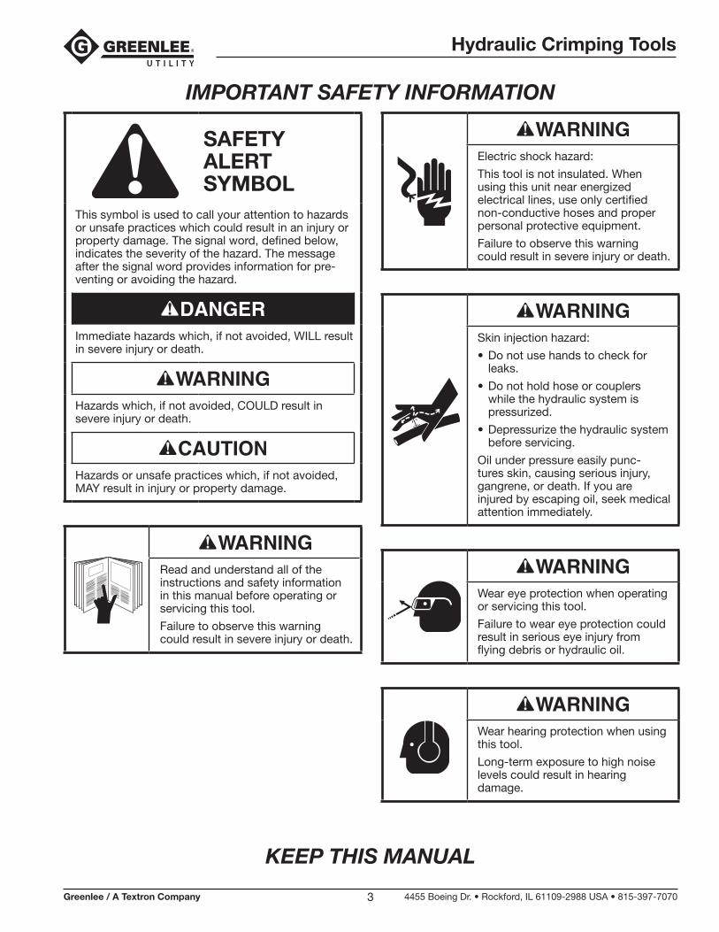
SAFETY ALERT SYMBOL
This symbol is used to call your attention to hazards or unsafe practices which could result in an injury or property damage. The signal word, defined below, indicates the severity of the hazard. The message after the signal word provides information for pre-venting or avoiding the hazard.
Immediate hazards which, if not avoided, WILL result in severe injury or death.
Hazards which, if not avoided, COULD result in severe injury or death.
Hazards or unsafe practices which, if not avoided, MAY result in injury or property damage.
Read and understand all of the instructions and safety information in this manual before operating or servicing this tool.
Failure to observe this warning could result in severe injury or death.
Electric shock hazard:
This tool is not insulated. When using this unit near energized electrical lines, use only certified non-conductive hoses and proper personal protective equipment.
Failure to observe this warning could result in severe injury or death.
Skin injection hazard:
• Do not use hands to check for leaks.
• Do not hold hose or couplers while the hydraulic system is pressurized.
• Depressurize the hydraulic system before servicing.
Oil under pressure easily punc-tures skin, causing serious injury, gangrene, or death. If you are injured by escaping oil, seek medical attention immediately.
Wear eye protection when operating or servicing this tool.
Failure to wear eye protection could result in serious eye injury from flying debris or hydraulic oil.
Wear hearing protection when using this tool.
Long-term exposure to high noise levels could result in hearing damage.
Hydraulic Crimping Tools
Greenlee / A Textron Company 4455 Boeing Dr. • Rockford, IL 61109-2988 USA • 815-397-70704
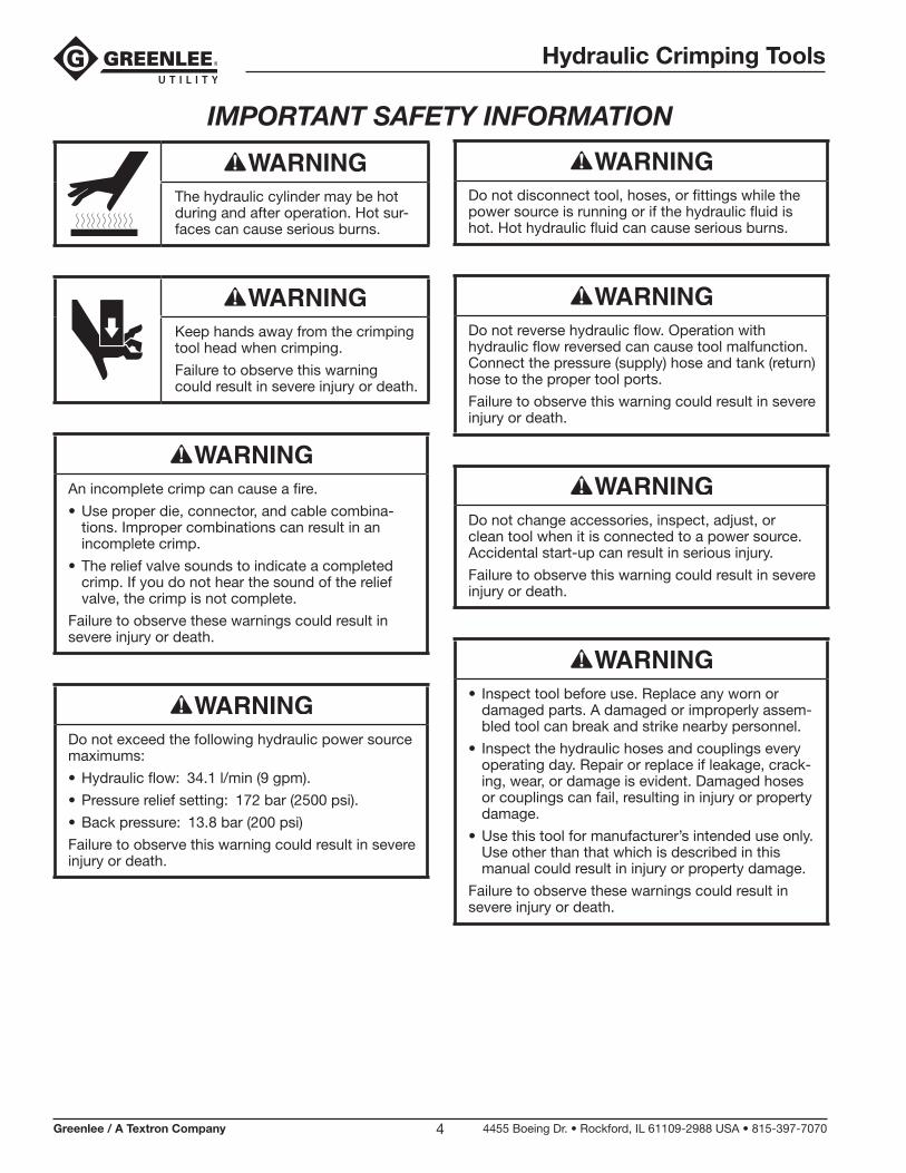
The hydraulic cylinder may be hot during and after operation. Hot sur-faces can cause serious burns.
Keep hands away from the crimping tool head when crimping.
Failure to observe this warning could result in severe injury or death.
An incomplete crimp can cause a fire.
• Use proper die, connector, and cable combina-tions. Improper combinations can result in an incomplete crimp.
• The relief valve sounds to indicate a completed crimp. If you do not hear the sound of the relief valve, the crimp is not complete.
Failure to observe these warnings could result in severe injury or death.
Do not exceed the following hydraulic power source maximums:
• Hydraulic flow: 34.1 l/min (9 gpm).
• Pressure relief setting: 172 bar (2500 psi).
• Back pressure: 13.8 bar (200 psi)
Failure to observe this warning could result in severe injury or death.
Do not disconnect tool, hoses, or fittings while the power source is running or if the hydraulic fluid is hot. Hot hydraulic fluid can cause serious burns.
Do not reverse hydraulic flow. Operation with hydraulic flow reversed can cause tool malfunction. Connect the pressure (supply) hose and tank (return) hose to the proper tool ports.
Failure to observe this warning could result in severe injury or death.
Do not change accessories, inspect, adjust, or clean tool when it is connected to a power source. Accidental start-up can result in serious injury.
Failure to observe this warning could result in severe injury or death.
• Inspect tool before use. Replace any worn or damaged parts. A damaged or improperly assem-bled tool can break and strike nearby personnel.
• Inspect the hydraulic hoses and couplings every operating day. Repair or replace if leakage, crack-ing, wear, or damage is evident. Damaged hoses or couplings can fail, resulting in injury or property damage.
• Use this tool for manufacturer’s intended use only. Use other than that which is described in this manual could result in injury or property damage.
Failure to observe these warnings could result in severe injury or death.
IMPORTANT SAFETY INFORMATION
Hydraulic Crimping Tools
Greenlee / A Textron Company 4455 Boeing Dr. • Rockford, IL 61109-2988 USA • 815-397-70705
IMPORTANT SAFETY INFORMATION
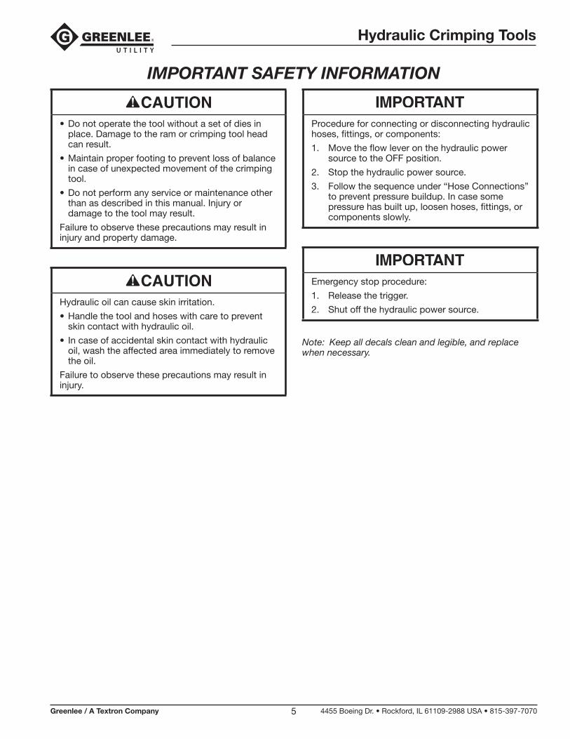
• Do not operate the tool without a set of dies in place. Damage to the ram or crimping tool head can result.
• Maintain proper footing to prevent loss of balance in case of unexpected movement of the crimping tool.
• Do not perform any service or maintenance other than as described in this manual. Injury or damage to the tool may result.
Failure to observe these precautions may result in injury and property damage.
Hydraulic oil can cause skin irritation.
• Handle the tool and hoses with care to prevent skin contact with hydraulic oil.
• In case of accidental skin contact with hydraulic oil, wash the affected area immediately to remove the oil.
Failure to observe these precautions may result in injury.
Procedure for connecting or disconnecting hydraulic hoses, fittings, or components:
1. Move the flow lever on the hydraulic power source to the OFF position.
2. Stop the hydraulic power source.
3. Follow the sequence under “Hose Connections” to prevent pressure buildup. In case some pressure has built up, loosen hoses, fittings, or components slowly.
Emergency stop procedure:
1. Release the trigger.
2. Shut off the hydraulic power source.
Note: Keep all decals clean and legible, and replace when necessary.
Hydraulic Crimping Tools
Greenlee / A Textron Company 4455 Boeing Dr. • Rockford, IL 61109-2988 USA • 815-397-70706
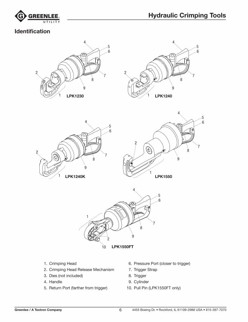
Identification
1. Crimping Head
2. Crimping Head Release Mechanism
3. Dies (not included)
4. Handle
5. Return Port (farther from trigger)
6. Pressure Port (closer to trigger)
7. Trigger Strap
8. Trigger
9. Cylinder
10. Pull Pin (LPK1550FT only)
LPK1230 LPK1240
LPK1240K LPK1550
1
2
456
8
9
7
1
2
456
8
9
7
1
2
456
8
9
7
2
456
8
9
7
1
LPK1550FT
1
8
9
10
456
2
7
Hydraulic Crimping Tools
Greenlee / A Textron Company 4455 Boeing Dr. • Rockford, IL 61109-2988 USA • 815-397-70707
SpecificationsCrimping Tool—All Models
Type of Hydraulic System: Open-center or closed-center
Hydraulic Ports:Pressure (supply): 3/4-16 UNF SAE O-ring BossTank (return): 3/4-16 UNF SAE O-ring Boss
Noise Levels LWA (Sound Power Level): 55.5 dBLpCpeak (Peak Emission Sound Pressure Level):
68.8 dB
Vibration: 3.15 ms2
LPK1230 Crimping Tool
Stroke (with dies): 30 mm (1.19")
Crimping Force @ 103 bar (1500 psi): 106.7 kN (24,000 lb)
Mass/Weight: 8.4 kg (18.5 lb)
Length: 490 mm (19.3")
Width: 140 mm (5.5")
LPK1240 Crimping Tool
Stroke (with dies): 42 mm (1.65")
Crimping Force @ 103 bar (1500 psi): 106.7 kN (24,000 lb)
Mass/Weight: 8.9 kg (19.7 lb)
Length: 516 mm (20.3")
Width: 140 mm (5.5")
LPK1240K Crimping Tool
Stroke (with dies): 41 mm (1.62")
Crimping Force @ 103 bar (1500 psi): 106.7 kN (24,000 lb)
Mass/Weight: 8.8 kg (19.5 lb)
Length: 516 mm (20.3")
Width: 140 mm (5.5")
LPK1550 Crimping Tool
Stroke (without dies): 58 mm (2.28")
Crimping Force @ 103 bar (1500 psi): 133 kN (30,000 lb)
Mass/Weight: 13.0 kg (28.6 lb)
Length: 605 mm (23.8")
Width: 165 mm (6.5")
LPK1550FT Crimping Tool
Stroke (without dies): 50.8 mm (2.00")
Crimping Force @ 103 bar (1500 psi): 133 kN (30,000 lb)
Mass/Weight: 11.1 kg (24.5 lb)
Length: 602 mm (23.7")
Width: 165 mm (6.5")
Hydraulic Crimping Tools
Greenlee / A Textron Company 4455 Boeing Dr. • Rockford, IL 61109-2988 USA • 815-397-70708
Specifications (cont’d)
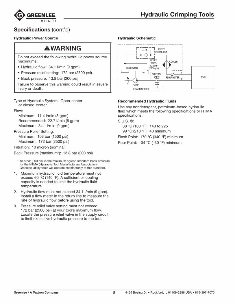
Hydraulic Power Source
Do not exceed the following hydraulic power source maximums:
• Hydraulic flow: 34.1 l/min (9 gpm).
• Pressure relief setting: 172 bar (2500 psi).
• Back pressure: 13.8 bar (200 psi)
Failure to observe this warning could result in severe injury or death.
Type of Hydraulic System: Open-center or closed-center
Flow:Minimum: 11.4 l/min (3 gpm)Recommended: 22.7 l/min (6 gpm)Maximum: 34.1 l/min (9 gpm)
Pressure Relief Setting:Minimum: 103 bar (1500 psi)Maximum: 172 bar (2500 psi)
Filtration: 10 micron (nominal)
Back Pressure (maximum*): 13.8 bar (200 psi)
* 13.8 bar (200 psi) is the maximum agreed standard back pressure for the HTMA (Hydraulic Tool Manufacturers Association). Greenlee Utility tools will operate satisfactorily at this standard.
1. Maximum hydraulic fluid temperature must not exceed 60 °C (140 °F). A sufficient oil cooling capacity is needed to limit the hydraulic fluid temperature.
2. Hydraulic flow must not exceed 34.1 l/min (9 gpm). Install a flow meter in the return line to measure the rate of hydraulic flow before using the tool.
3. Pressure relief valve setting must not exceed 172 bar (2500 psi) at your tool’s maximum flow. Locate the pressure relief valve in the supply circuit to limit excessive hydraulic pressure to the tool.
Hydraulic Schematic
FILTER(10 MICRON)
COOLERRELIEFVALVE
172 bar(2500 psi)
CONTROLVALVE FLOW METER
T
PTOOL
RESERVOIR
PUMP
POWER SOURCE
Recommended Hydraulic Fluids
Use any nondetergent, petroleum-based hydraulic fluid which meets the following specifications or HTMA specifications.
S.U.S. @:38 °C (100 °F): 140 to 22599 °C (210 °F): 40 minimum
Flash Point: 170 °C (340 °F) minimum
Pour Point: –34 °C (–30 °F) minimum
Hydraulic Crimping Tools
Greenlee / A Textron Company 4455 Boeing Dr. • Rockford, IL 61109-2988 USA • 815-397-70709
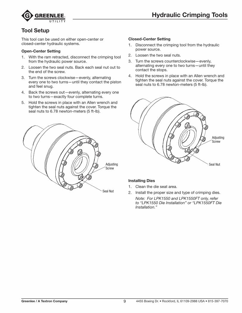
Tool Setup
This tool can be used on either open-center or closed-center hydraulic systems.
Open-Center Setting
1. With the ram retracted, disconnect the crimping tool from the hydraulic power source.
2. Loosen the two seal nuts. Back each seal nut out to the end of the screw.
3. Turn the screws clockwise—evenly, alternating every one to two turns—until they contact the piston and feel snug.
4. Back the screws out—evenly, alternating every one to two turns—exactly four complete turns.
5. Hold the screws in place with an Allen wrench and tighten the seal nuts against the cover. Torque the seal nuts to 6.78 newton-meters (5 ft-lb).
AdjustingScrew
Seal Nut
Closed-Center Setting
1. Disconnect the crimping tool from the hydraulic power source.
2. Loosen the two seal nuts.
3. Turn the screws counterclockwise—evenly, alternating every one to two turns—until they contact the stops.
4. Hold the screws in place with an Allen wrench and tighten the seal nuts against the cover. Torque the seal nuts to 6.78 newton-meters (5 ft-lb).
AdjustingScrew
Seal Nut
Installing Dies
1. Clean the die seat area.
2. Install the proper size and type of crimping dies.
Note: For LPK1550 and LPK1550FT only, refer to “LPK1550 Die Installation” or “LPK1550FT Die Installation.”
Hydraulic Crimping Tools
Greenlee / A Textron Company 4455 Boeing Dr. • Rockford, IL 61109-2988 USA • 815-397-707010
Hoses and FittingsInstallation and Maintenance
Refer to publication 99930323, SAE J1273 (Hose and Hose Assemblies).
Replacement
Refer to a Greenlee Utility catalog or publication 99910322, Low Pressure Quick Couplers, Adapters and Hoses.
Do not disconnect tool, hoses, or fittings while the power source is running or if the hydraulic fluid is hot. Hot hydraulic fluid can cause serious burns.
Hose ConnectionsTool Port Identification
Three methods are used to identify the pressure and return ports of Greenlee Utility tools. Match the mark-ings on your tool to this table.
Pressure Port Return Port
P T
or
In Out
or
3/4–16 O-ring Boss
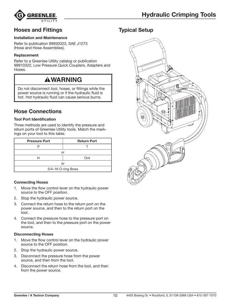
Connecting Hoses
1. Move the flow control lever on the hydraulic power source to the OFF position.
2. Stop the hydraulic power source.
3. Connect the return hose to the return port on the power source, and then to the return port on the tool.
4. Connect the pressure hose to the pressure port on the tool, and then to the pressure port on the power source.
Disconnecting Hoses
1. Move the flow control lever on the hydraulic power source to the OFF position.
2. Stop the hydraulic power source.
3. Disconnect the pressure hose from the power source, and then from the tool.
4. Disconnect the return hose from the tool, and then from the power source.
Typical Setup
Hydraulic Crimping Tools
Greenlee / A Textron Company 4455 Boeing Dr. • Rockford, IL 61109-2988 USA • 815-397-707011
Operation
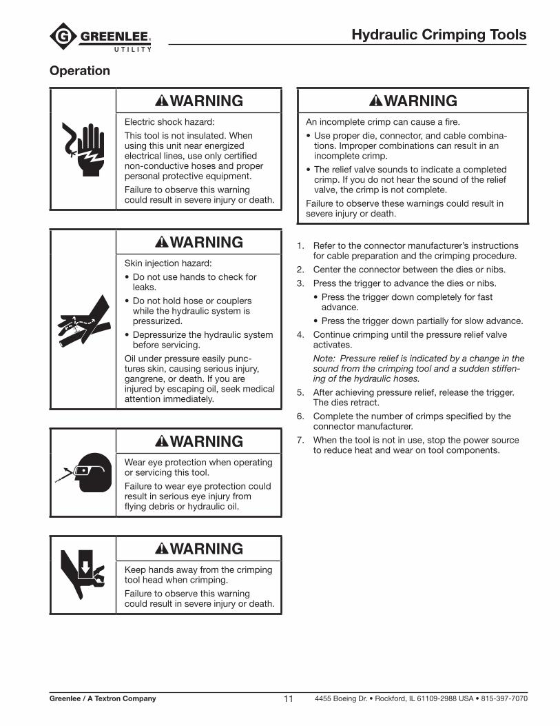
Electric shock hazard:
This tool is not insulated. When using this unit near energized electrical lines, use only certified non-conductive hoses and proper personal protective equipment.
Failure to observe this warning could result in severe injury or death.
Skin injection hazard:
• Do not use hands to check for leaks.
• Do not hold hose or couplers while the hydraulic system is pressurized.
• Depressurize the hydraulic system before servicing.
Oil under pressure easily punc-tures skin, causing serious injury, gangrene, or death. If you are injured by escaping oil, seek medical attention immediately.
Wear eye protection when operating or servicing this tool.
Failure to wear eye protection could result in serious eye injury from flying debris or hydraulic oil.
Keep hands away from the crimping tool head when crimping.
Failure to observe this warning could result in severe injury or death.
An incomplete crimp can cause a fire.
• Use proper die, connector, and cable combina-tions. Improper combinations can result in an incomplete crimp.
• The relief valve sounds to indicate a completed crimp. If you do not hear the sound of the relief valve, the crimp is not complete.
Failure to observe these warnings could result in severe injury or death.
1. Refer to the connector manufacturer’s instructions for cable preparation and the crimping procedure.
2. Center the connector between the dies or nibs.
3. Press the trigger to advance the dies or nibs.
• Press the trigger down completely for fast advance.
• Press the trigger down partially for slow advance.
4. Continue crimping until the pressure relief valve activates.
Note: Pressure relief is indicated by a change in the sound from the crimping tool and a sudden stiffen-ing of the hydraulic hoses.
5. After achieving pressure relief, release the trigger. The dies retract.
6. Complete the number of crimps specified by the connector manufacturer.
7. When the tool is not in use, stop the power source to reduce heat and wear on tool components.
Hydraulic Crimping Tools
Greenlee / A Textron Company 4455 Boeing Dr. • Rockford, IL 61109-2988 USA • 815-397-707012
LPK1550 Die Installation
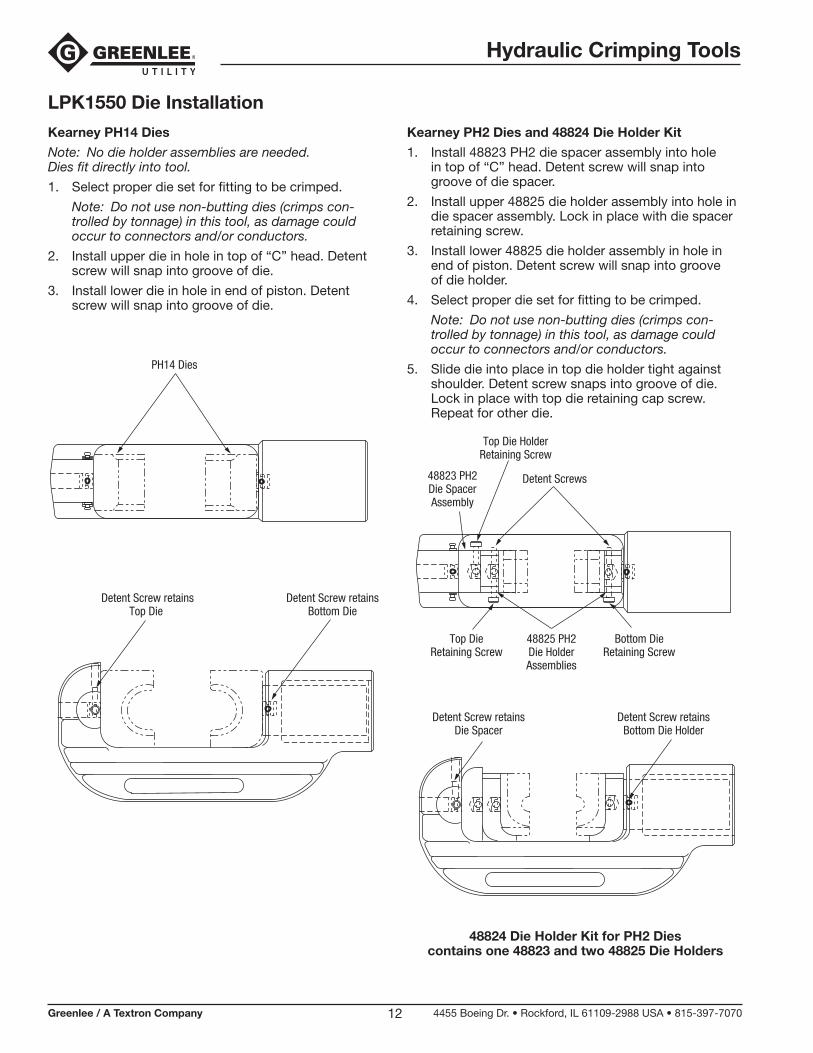
Kearney PH14 Dies
Note: No die holder assemblies are needed. Dies fit directly into tool.
1. Select proper die set for fitting to be crimped.
Note: Do not use non-butting dies (crimps con-trolled by tonnage) in this tool, as damage could occur to connectors and/or conductors.
2. Install upper die in hole in top of “C” head. Detent screw will snap into groove of die.
3. Install lower die in hole in end of piston. Detent screw will snap into groove of die.
Kearney PH2 Dies and 48824 Die Holder Kit
1. Install 48823 PH2 die spacer assembly into hole in top of “C” head. Detent screw will snap into groove of die spacer.
2. Install upper 48825 die holder assembly into hole in die spacer assembly. Lock in place with die spacer retaining screw.
3. Install lower 48825 die holder assembly in hole in end of piston. Detent screw will snap into groove of die holder.
4. Select proper die set for fitting to be crimped.
Note: Do not use non-butting dies (crimps con-trolled by tonnage) in this tool, as damage could occur to connectors and/or conductors.
5. Slide die into place in top die holder tight against shoulder. Detent screw snaps into groove of die. Lock in place with top die retaining cap screw. Repeat for other die.
Detent Screws
Detent Screw retainsBottom Die Holder
Detent Screw retainsDie Spacer
Top Die HolderRetaining Screw
Top DieRetaining Screw
Bottom DieRetaining Screw
48825 PH2Die HolderAssemblies
48823 PH2Die SpacerAssembly
48824 Die Holder Kit for PH2 Dies contains one 48823 and two 48825 Die Holders
PH14 Dies
Detent Screw retainsBottom Die
Detent Screw retainsTop Die
Hydraulic Crimping Tools
Greenlee / A Textron Company 4455 Boeing Dr. • Rockford, IL 61109-2988 USA • 815-397-707013
LPK1550 Die Installation (cont’d)
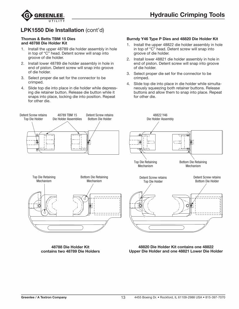
Thomas & Betts TBM 15 Dies and 48788 Die Holder Kit
1. Install the upper 48789 die holder assembly in hole in top of “C” head. Detent screw will snap into groove of die holder.
2. Install lower 48789 die holder assembly in hole in end of piston. Detent screw will snap into groove of die holder.
3. Select proper die set for the connector to be crimped.
4. Slide top die into place in die holder while depress-ing die retainer button. Release die button while it snaps into place, locking die into position. Repeat for other die.
48789 TBM 15Die Holder Assemblies
Bottom Die RetainingMechanism
Top Die RetainingMechanism
Detent Screw retainsTop Die Holder
Detent Screw retainsBottom Die Holder
48788 Die Holder Kit contains two 48789 Die Holders
Burndy Y46 Type P Dies and 48820 Die Holder Kit
1. Install the upper 48822 die holder assembly in hole in top of “C” head. Detent screw will snap into groove of die holder.
2. Install lower 48821 die holder assembly in hole in end of piston. Detent screw will snap into groove of die holder.
3. Select proper die set for the connector to be crimped.
4. Slide top die into place in die holder while simulta-neously squeezing both retainer buttons. Release buttons and allow them to snap into place. Repeat for other die.
Detent Screw retainsBottom Die Holder
Detent Screw retainsTop Die Holder
Top Die RetainingMechanism
48822 Y46Die Holder Assembly
Bottom Die RetainingMechanism
48820 Die Holder Kit contains one 48822 Upper Die Holder and one 48821 Lower Die Holder
Hydraulic Crimping Tools
Greenlee / A Textron Company 4455 Boeing Dr. • Rockford, IL 61109-2988 USA • 815-397-707014
LPK1550 Die Installation (cont’d)
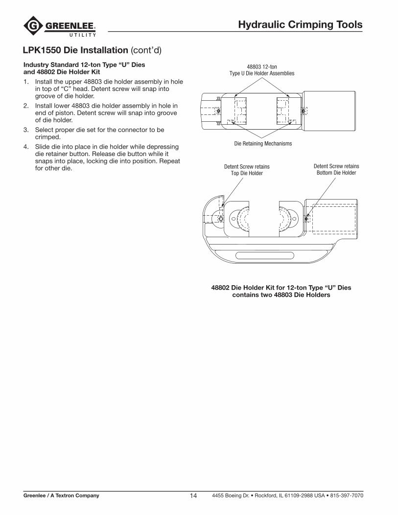
Industry Standard 12-ton Type “U” Dies and 48802 Die Holder Kit
1. Install the upper 48803 die holder assembly in hole in top of “C” head. Detent screw will snap into groove of die holder.
2. Install lower 48803 die holder assembly in hole in end of piston. Detent screw will snap into groove of die holder.
3. Select proper die set for the connector to be crimped.
4. Slide die into place in die holder while depressing die retainer button. Release die button while it snaps into place, locking die into position. Repeat for other die. Detent Screw retains
Bottom Die HolderDetent Screw retains
Top Die Holder
48803 12-tonType U Die Holder Assemblies
Die Retaining Mechanisms
48802 Die Holder Kit for 12-ton Type “U” Dies contains two 48803 Die Holders
Hydraulic Crimping Tools
Greenlee / A Textron Company 4455 Boeing Dr. • Rockford, IL 61109-2988 USA • 815-397-707015
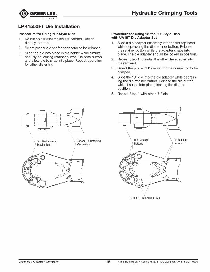
LPK1550FT Die InstallationProcedure for Using “P” Style Dies
1. No die holder assemblies are needed. Dies fit directly into tool.
2. Select proper die set for connector to be crimped.
3. Slide top die into place in die holder while simulta-neously squeezing retainer button. Release button and allow die to snap into place. Repeat operation for other die entry.
Procedure for Using 12-ton “U” Style Dies with UA15T Die Adapter Set
1. Slide a die adapter assembly into the flip-top head while depressing the die retainer button. Release the retainer button while the adapter snaps into place. The die adapter should be locked in position.
2. Repeat Step 1 to install the other die adapter into the ram end.
3. Select the proper “U” die set for the connector to be crimped.
4. Slide the “U” die into the die adapter while depress-ing the die retainer button. Release the die button while it snaps into place, locking the die into position.
5. Repeat Step 4 with other “U” die.
Top Die RetainingMechanism
Bottom Die RetainingMechanism
Die RetainerButtons
Die RetainerButtons
12-ton “U” Die Adapter Set
Hydraulic Crimping Tools
Greenlee / A Textron Company 4455 Boeing Dr. • Rockford, IL 61109-2988 USA • 815-397-707016
Maintenance
Skin injection hazard:
• Do not use hands to check for leaks.
• Do not hold hose or couplers while the hydraulic system is pressurized.
• Depressurize the hydraulic system before servicing.
Oil under pressure easily punc-tures skin, causing serious injury, gangrene, or death. If you are injured by escaping oil, seek medical attention immediately.
Wear eye protection when operating or servicing this tool.
Failure to wear eye protection could result in serious eye injury from flying debris or hydraulic oil.
Notes:
(1) Keep all decals clean and legible. Replace decals when necessary.
(2) When disposing of any components (hydraulic hoses, hydraulic fluid, worn parts, etc.), do so in accordance with federal, state and local laws or ordinances.
Daily
1. Thoroughly wipe all tool surfaces clean. Remove any oxide inhibitor, connector contact compound, and grit from the die seat areas, dies and die holders.
2. Inspect the hydraulic hoses and fittings for signs of leaks, cracks, wear or damage. Replace if necessary.
3. Install dust caps over the hydraulic ports when the tool is disconnected.
Monthly
1. Perform a thorough inspection of the hydraulic hoses and fittings as described in publication 99930323, SAE J1273 (Hose and Hose Assemblies).
2. Apply a light oil to all moving parts.
Quarterly or Every 500 Crimps
Perform the “Periodic Pressure Relief Valve Check.”
Annually
If required by your organization’s regulations, send the tool to a Greenlee Utility Authorized Service Center.
Periodic Pressure Relief Valve Check
Test the crimping tool periodically to ensure that the pressure relief valve activates at the proper pressure.
1. Test the crimping tool with either a Greenlee load cell or with an in-line pressure gauge.
• Purchase a Greenlee Load Cell, catalog number 35887. Refer to the instructions supplied with the load cell.
• Install an in-line pressure gauge on the input side of the tool. With dies in place, perform a test crimp.
2. Pressure relief should occur at 103 to 107 bar (1500 to 1550 psi).
3. If pressure relief occurs outside of the specified range, send the crimping tool to a Greenlee Utility Authorized Service Center.
Hydraulic Crimping Tools
Greenlee / A Textron Company 4455 Boeing Dr. • Rockford, IL 61109-2988 USA • 815-397-707017
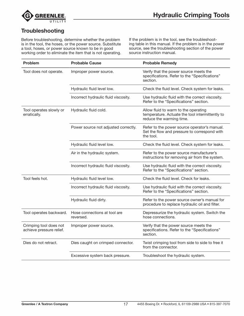
Problem Probable Cause Probable Remedy
Tool does not operate. Improper power source. Verify that the power source meets the specifications. Refer to the “Specifications” section.
Hydraulic fluid level low. Check the fluid level. Check system for leaks.
Incorrect hydraulic fluid viscosity. Use hydraulic fluid with the correct viscosity. Refer to the “Specifications” section.
Tool operates slowly or erratically.
Hydraulic fluid cold. Allow fluid to warm to the operating temperature. Actuate the tool intermittently to reduce the warming time.
Power source not adjusted correctly. Refer to the power source operator’s manual. Set the flow and pressure to correspond with the tool.
Hydraulic fluid level low. Check the fluid level. Check system for leaks.
Air in the hydraulic system. Refer to the power source manufacturer’s instructions for removing air from the system.
Incorrect hydraulic fluid viscosity. Use hydraulic fluid with the correct viscosity. Refer to the “Specifications” section.
Tool feels hot. Hydraulic fluid level low. Check the fluid level. Check for leaks.
Incorrect hydraulic fluid viscosity. Use hydraulic fluid with the correct viscosity. Refer to the “Specifications” section.
Hydraulic fluid dirty. Refer to the power source owner’s manual for procedure to replace hydraulic oil and filter.
Tool operates backward. Hose connections at tool are reversed.
Depressurize the hydraulic system. Switch the hose connections.
Crimping tool does not achieve pressure relief.
Improper power source. Verify that the power source meets the specifications. Refer to the “Specifications” section.
Dies do not retract. Dies caught on crimped connector. Twist crimping tool from side to side to free it from the connector.
Excessive system back pressure. Troubleshoot the hydraulic system.
Troubleshooting
Before troubleshooting, determine whether the problem is in the tool, the hoses, or the power source. Substitute a tool, hoses, or power source known to be in good working order to eliminate the item that is not operating.
If the problem is in the tool, see the troubleshoot-ing table in this manual. If the problem is in the power source, see the troubleshooting section of the power source instruction manual.
Hydraulic Crimping Tools
Greenlee / A Textron Company 4455 Boeing Dr. • Rockford, IL 61109-2988 USA • 815-397-707018
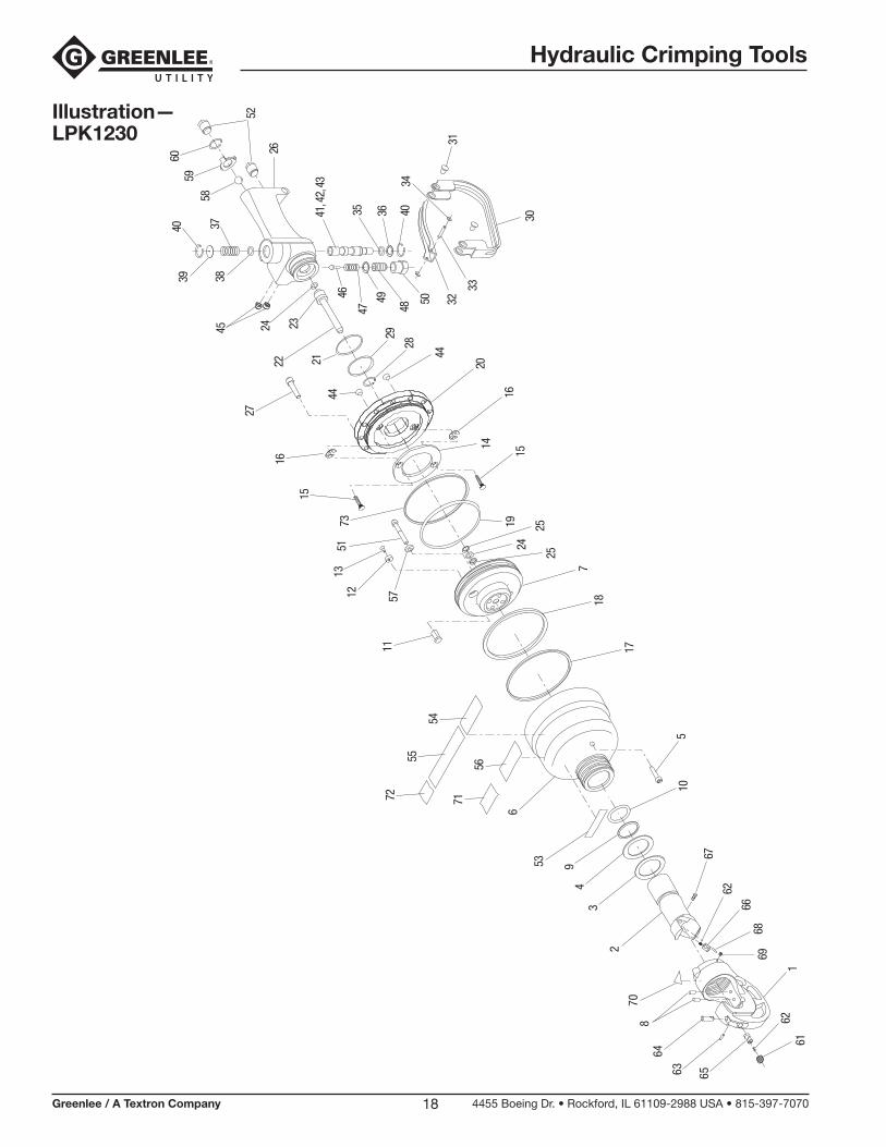
Illustration— LPK1230
2
70
64
63 65
8
34
953
11
12 57
1351
27
4039
3738
22
45
105
6
17
73
187
24
2525
30
32
34
31
33
28
26
35 36 40
47
46 50
48
49
55
72
54
2014
29
44
1615
19
15
16
44
24 23
2141
, 42,
43
56
71
67
61
6968
66
62
621
52
58
6059
Hydraulic Crimping Tools
Greenlee / A Textron Company 4455 Boeing Dr. • Rockford, IL 61109-2988 USA • 815-397-707019
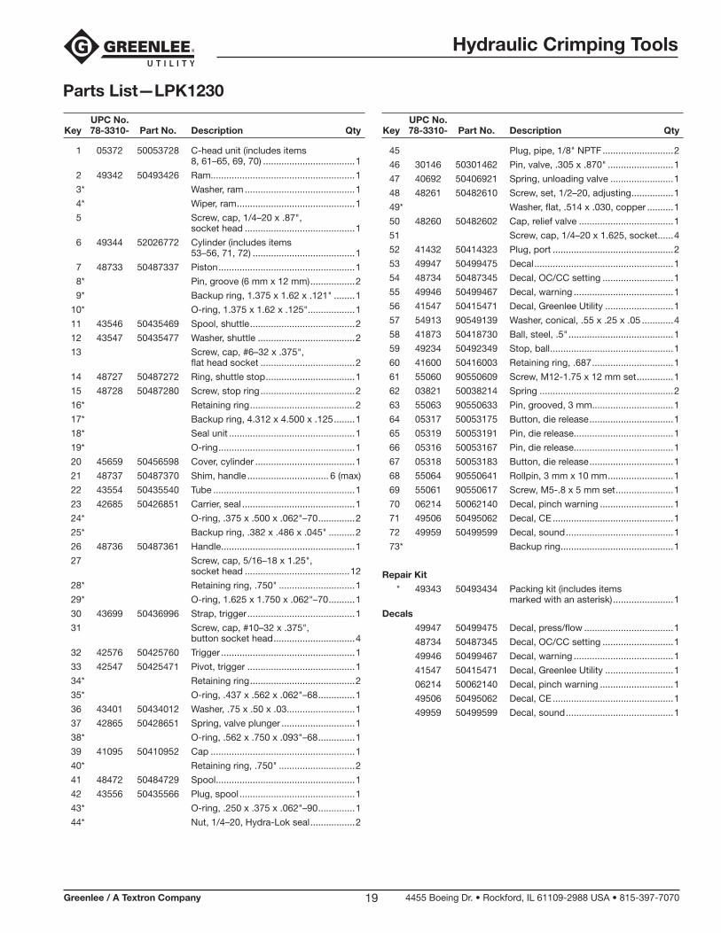
Parts List—LPK1230
UPC No. Key 78-3310- Part No. Description Qty
1 05372 50053728 C-head unit (includes items 8, 61–65, 69, 70) ...................................1
2 49342 50493426 Ram.......................................................1
3* Washer, ram ..........................................1
4* Wiper, ram .............................................1
5 Screw, cap, 1/4–20 x .87", socket head ..........................................1
6 49344 52026772 Cylinder (includes items 53–56, 71, 72) .......................................1
7 48733 50487337 Piston ....................................................1
8* Pin, groove (6 mm x 12 mm) .................2
9* Backup ring, 1.375 x 1.62 x .121" ........1
10* O-ring, 1.375 x 1.62 x .125"..................1
11 43546 50435469 Spool, shuttle ........................................2
12 43547 50435477 Washer, shuttle .....................................2
13 Screw, cap, #6–32 x .375", flat head socket ....................................2
14 48727 50487272 Ring, shuttle stop ..................................1
15 48728 50487280 Screw, stop ring ....................................2
16* Retaining ring ........................................2
17* Backup ring, 4.312 x 4.500 x .125 ........1
18* Seal unit ................................................1
19* O-ring ....................................................1
20 45659 50456598 Cover, cylinder ......................................1
21 48737 50487370 Shim, handle ............................... 6 (max)
22 43554 50435540 Tube ......................................................1
23 42685 50426851 Carrier, seal ...........................................1
24* O-ring, .375 x .500 x .062"–70 ..............2
25* Backup ring, .382 x .486 x .045" ..........2
26 48736 50487361 Handle ...................................................1
27 Screw, cap, 5/16–18 x 1.25", socket head ........................................12
28* Retaining ring, .750" .............................1
29* O-ring, 1.625 x 1.750 x .062"–70 ..........1
30 43699 50436996 Strap, trigger .........................................1
31 Screw, cap, #10–32 x .375", button socket head ...............................4
32 42576 50425760 Trigger ...................................................1
33 42547 50425471 Pivot, trigger .........................................1
34* Retaining ring ........................................2
35* O-ring, .437 x .562 x .062"–68 ..............1
36 43401 50434012 Washer, .75 x .50 x .03..........................1
37 42865 50428651 Spring, valve plunger ............................1
38* O-ring, .562 x .750 x .093"–68 ..............1
39 41095 50410952 Cap .......................................................1
40* Retaining ring, .750" .............................2
41 48472 50484729 Spool .....................................................1
42 43556 50435566 Plug, spool ............................................1
43* O-ring, .250 x .375 x .062"–90 ..............1
44* Nut, 1/4–20, Hydra-Lok seal .................2
UPC No. Key 78-3310- Part No. Description Qty
45 Plug, pipe, 1/8" NPTF ...........................2
46 30146 50301462 Pin, valve, .305 x .870" .........................1
47 40692 50406921 Spring, unloading valve ........................1
48 48261 50482610 Screw, set, 1/2–20, adjusting ................1
49* Washer, flat, .514 x .030, copper ..........1
50 48260 50482602 Cap, relief valve ....................................1
51 Screw, cap, 1/4–20 x 1.625, socket ......4
52 41432 50414323 Plug, port ..............................................2
53 49947 50499475 Decal .....................................................1
54 48734 50487345 Decal, OC/CC setting ...........................1
55 49946 50499467 Decal, warning ......................................1
56 41547 50415471 Decal, Greenlee Utility ..........................1
57 54913 90549139 Washer, conical, .55 x .25 x .05 ............4
58 41873 50418730 Ball, steel, .5" ........................................1
59 49234 50492349 Stop, ball ...............................................1
60 41600 50416003 Retaining ring, .687 ...............................1
61 55060 90550609 Screw, M12-1.75 x 12 mm set ..............1
62 03821 50038214 Spring ...................................................2
63 55063 90550633 Pin, grooved, 3 mm...............................1
64 05317 50053175 Button, die release ................................1
65 05319 50053191 Pin, die release......................................1
66 05316 50053167 Pin, die release......................................1
67 05318 50053183 Button, die release ................................1
68 55064 90550641 Rollpin, 3 mm x 10 mm .........................1
69 55061 90550617 Screw, M5-.8 x 5 mm set ......................1
70 06214 50062140 Decal, pinch warning ............................1
71 49506 50495062 Decal, CE ..............................................1
72 49959 50499599 Decal, sound .........................................1
73* Backup ring ...........................................1
Repair Kit
* 49343 50493434 Packing kit (includes items marked with an asterisk) .......................1
Decals
49947 50499475 Decal, press/flow ..................................1
48734 50487345 Decal, OC/CC setting ...........................1
49946 50499467 Decal, warning ......................................1
41547 50415471 Decal, Greenlee Utility ..........................1
06214 50062140 Decal, pinch warning ............................1
49506 50495062 Decal, CE ..............................................1
49959 50499599 Decal, sound .........................................1
Hydraulic Crimping Tools
Greenlee / A Textron Company 4455 Boeing Dr. • Rockford, IL 61109-2988 USA • 815-397-707020
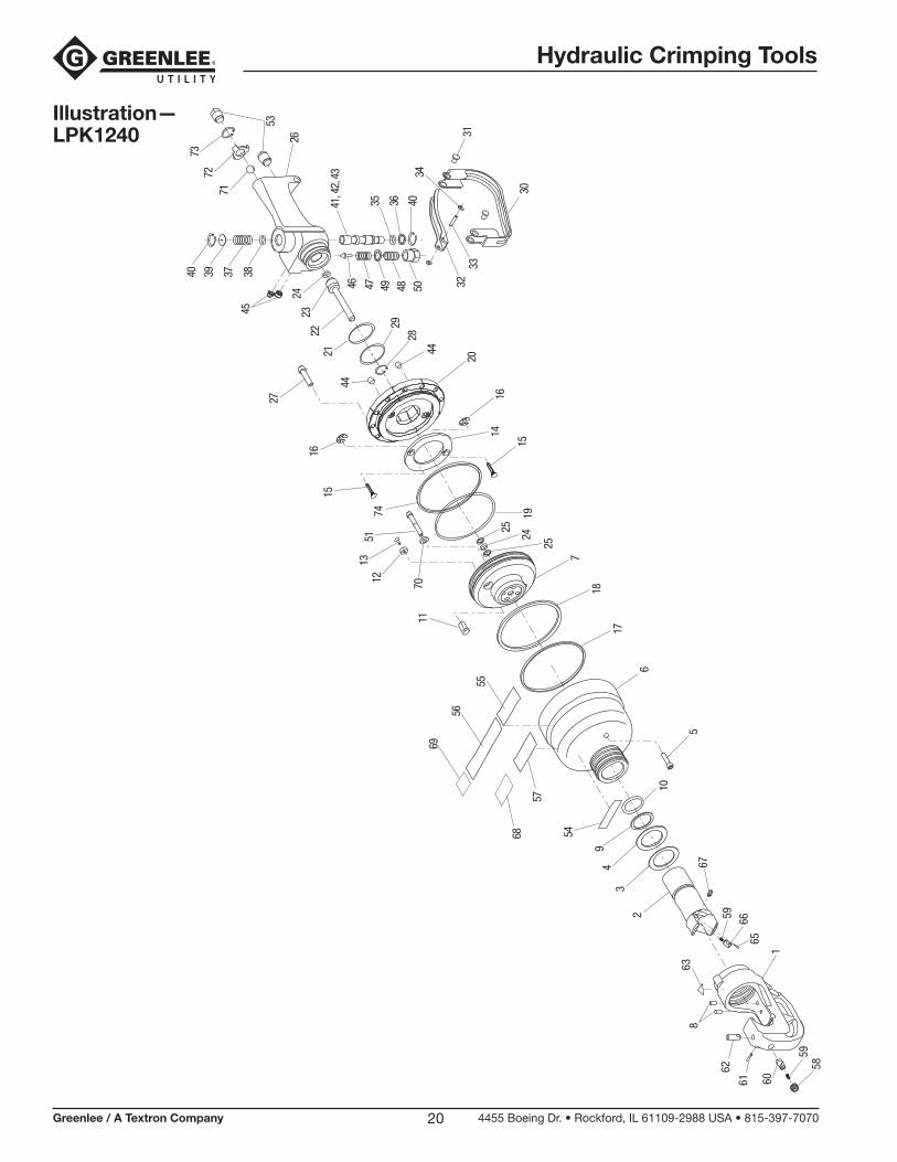
Illustration— LPK1240
2
34
9
54
6
11
12 70
1351
27
40 39 37 38
22
45
10
5
17
74
18
7
25
24
25
30
32
34
3133
28
26
41, 4
2, 4
3
35 36 40
4746 504849
56
69
5520
14
29
44
16
1519
1516
44
2423
21
57
68
53
71
7372
65
63
6659
67
5859
61
62
1
8
60
Hydraulic Crimping Tools
Greenlee / A Textron Company 4455 Boeing Dr. • Rockford, IL 61109-2988 USA • 815-397-707021
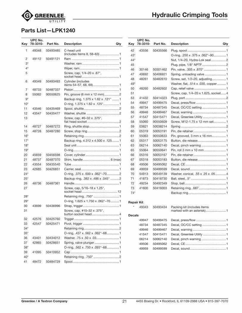
Parts List—LPK1240
UPC No. Key 78-3310- Part No. Description Qty
1 49348 50493485 C-head unit (includes items 8, 58–63) ......................1
2 49112 50491121 Ram ......................................................1
3* Washer, ram ..........................................1
4* Wiper, ram .............................................1
5 Screw, cap, 1/4–20 x .87", socket head ..........................................1
6 49349 50493493 Cylinder (includes items 54–57, 68, 69)..............................1
7 48733 50487337 Piston ....................................................1
8 55062 90550625 Pin, groove (6 mm x 12 mm) .................2
9* Backup ring, 1.375 x 1.62 x .121" ........1
10* O-ring, 1.375 x 1.62 x .125"..................1
11 43546 50435469 Spool, shuttle ........................................2
12 43547 50435477 Washer, shuttle .....................................2
13 Screw, cap, #6–32 x .375", flat head socket ....................................2
14 48727 50487272 Ring, shuttle stop ..................................1
15 48728 50487280 Screw, stop ring ....................................2
16* Retaining ring ........................................2
17* Backup ring, 4.312 x 4.500 x .125 ........1
18* Seal unit ................................................1
19* O-ring ....................................................1
20 45659 50456598 Cover, cylinder ......................................1
21 48737 50487370 Shim, handle ............................... 6 (max)
22 43554 50435540 Tube ......................................................1
23 42685 50426851 Carrier, seal ...........................................1
24* O-ring, .375 x .500 x .062"–70 ..............2
25* Backup ring, .382 x .486 x .045" ..........2
26 48736 50487361 Handle ...................................................1
27 Screw, cap, 5/16–18 x 1.25", socket head ........................................12
28* Retaining ring, .750" .............................1
29* O-ring, 1.625 x 1.750 x .062"–70 ..........1
30 43699 50436996 Strap, trigger .........................................1
31 Screw, cap, #10–32 x .375", button socket head ...............................4
32 42576 50425760 Trigger ...................................................1
33 42547 50425471 Pivot, trigger .........................................1
34* Retaining ring ........................................2
35* O-ring, .437 x .562 x .062"–68 ..............1
36 43401 50434012 Washer, .75 x .50 x .03..........................1
37 42865 50428651 Spring, valve plunger ............................1
38* O-ring, .562 x .750 x .093"–68 ..............1
39 41095 50410952 Cap .......................................................1
40* Retaining ring, .750" .............................2
41 48472 50484729 Spool .....................................................1
UPC No. Key 78-3310- Part No. Description Qty
42 43556 50435566 Plug, spool ............................................1
43* O-ring, .250 x .375 x .062"–90 ..............1
44* Nut, 1/4–20, Hydra-Lok seal .................2
45 Plug, pipe, 1/8" NPTF ...........................2
46 30146 50301462 Pin, valve, .305 x .870" .........................1
47 40692 50406921 Spring, unloading valve ........................1
48 48261 50482610 Screw, set, 1/2–20, adjusting ................1
49* Washer, flat, .514 x .030, copper ..........1
50 48260 50482602 Cap, relief valve ....................................1
51 Screw, cap, 1/4–20 x 1.625, socket ......4
53 41432 50414323 Plug, port ..............................................2
54 49947 50499475 Decal, press/flow ..................................1
55 48734 50487345 Decal, OC/CC setting ...........................1
56 49946 50499467 Decal, warning ......................................1
57 41547 50415471 Decal, Greenlee Utility ..........................1
58 55060 90550609 Screw, M12-1.75 x 12 mm set ..............1
59 03821 50038214 Spring ...................................................2
60 05319 50053191 Pin, die retainer .....................................1
61 55063 90550633 Pin, grooved, 3 mm x 16 mm................1
62 05317 50053175 Button, die release ................................1
63 06214 50062140 Decal, pinch warning ............................1
65 55064 90550641 Pin, roll 3 mm x 10 mm .........................1
66 05316 50053167 Pin, die retainer .....................................1
67 05318 50053183 Button, die release ................................1
68 49506 50495062 Decal, CE ..............................................1
69 49959 50499599 Decal, sound .........................................1
70 54913 90549139 Washer, conical, .55 x .25 x .05 ............4
71 41873 50418730 Ball, steel, .5" ........................................1
72 49234 50492349 Stop, ball ...............................................1
73 41600 50416003 Retaining ring, .687 ...............................1
74* Backup ring ...........................................1
Repair Kit
* 49343 50493434 Packing kit (includes items marked with an asterisk) .......................1
Decals
49947 50499475 Decal, press/flow ..................................1
48734 50487345 Decal, OC/CC setting ...........................1
49946 50499467 Decal, warning ......................................1
41547 50415471 Decal, Greenlee Utility ..........................1
06214 50062140 Decal, pinch warning ............................1
49506 50495062 Decal, CE ..............................................1
49959 50499599 Decal, sound .........................................1
Hydraulic Crimping Tools
Greenlee / A Textron Company 4455 Boeing Dr. • Rockford, IL 61109-2988 USA • 815-397-707022
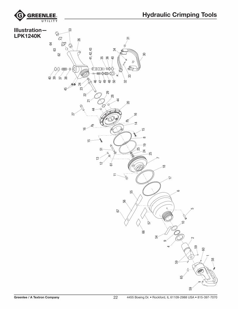
Illustration— LPK1240K
2
49
54
6
11
12 61
1351
27
40 39 37 38
22
45
10
5
17
8
18
7
25
24
25
30
32
34
3133
28
26
41, 4
2, 4
3
35 36 40
4746 504849
56
67
5520
14
29
44
16
1519
1516
44
2423
21
57
66
53
62
6463
581
60
59
59
59
65
Hydraulic Crimping Tools
Greenlee / A Textron Company 4455 Boeing Dr. • Rockford, IL 61109-2988 USA • 815-397-707023
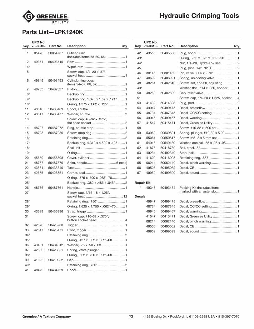
Parts List—LPK1240K
UPC No. Key 78-3310- Part No. Description Qty
1 05476 50054767 C-head unit (includes items 58-60, 65) .....................1
2 49351 50493515 Ram ......................................................1
4* Wiper, ram .............................................1
5 Screw, cap, 1/4–20 x .87", socket head ..........................................1
6 49349 50493493 Cylinder (includes items 54–57, 66, 67)..............................1
7 48733 50487337 Piston ....................................................1
8* Backup ring ...........................................1
9* Backup ring, 1.375 x 1.62 x .121" ........1
10* O-ring, 1.375 x 1.62 x .125"..................1
11 43546 50435469 Spool, shuttle ........................................2
12 43547 50435477 Washer, shuttle .....................................2
13 Screw, cap, #6–32 x .375", flat head socket ....................................2
14 48727 50487272 Ring, shuttle stop ..................................1
15 48728 50487280 Screw, stop ring ....................................2
16* Retaining ring ........................................2
17* Backup ring, 4.312 x 4.500 x .125 ........1
18* Seal unit ................................................1
19* O-ring ....................................................1
20 45659 50456598 Cover, cylinder ......................................1
21 48737 50487370 Shim, handle ............................... 6 (max)
22 43554 50435540 Tube ......................................................1
23 42685 50426851 Carrier, seal ...........................................1
24* O-ring, .375 x .500 x .062"–70 ..............2
25* Backup ring, .382 x .486 x .045" ..........2
26 48736 50487361 Handle ...................................................1
27 Screw, cap, 5/16–18 x 1.25", socket head ........................................12
28* Retaining ring, .750" .............................1
29* O-ring, 1.625 x 1.750 x .062"–70 ..........1
30 43699 50436996 Strap, trigger .........................................1
31 Screw, cap, #10–32 x .375", button socket head ...............................4
32 42576 50425760 Trigger ...................................................1
33 42547 50425471 Pivot, trigger .........................................1
34* Retaining ring ........................................2
35* O-ring, .437 x .562 x .062"–68 ..............1
36 43401 50434012 Washer, .75 x .50 x .03..........................1
37 42865 50428651 Spring, valve plunger ............................1
38* O-ring, .562 x .750 x .093"–68 ..............1
39 41095 50410952 Cap .......................................................1
40* Retaining ring, .750" .............................2
41 48472 50484729 Spool .....................................................1
UPC No. Key 78-3310- Part No. Description Qty
42 43556 50435566 Plug, spool ............................................1
43* O-ring, .250 x .375 x .062"–90 ..............1
44* Nut, 1/4–20, Hydra-Lok seal .................2
45 Plug, pipe, 1/8" NPTF ...........................2
46 30146 50301462 Pin, valve, .305 x .870" .........................1
47 40692 50406921 Spring, unloading valve ........................1
48 48261 50482610 Screw, set, 1/2–20, adjusting ................1
49* Washer, flat, .514 x .030, copper ..........1
50 48260 50482602 Cap, relief valve ....................................1
51 Screw, cap, 1/4–20 x 1.625, socket ......4
53 41432 50414323 Plug, port ..............................................2
54 49947 50499475 Decal, press/flow ..................................1
55 48734 50487345 Decal, OC/CC setting ...........................1
56 49946 50499467 Decal, warning ......................................1
57 41547 50415471 Decal, Greenlee Utility ..........................1
58 Screw, #10-32 x .500 set ......................1
59 53962 90539621 Spring, plunger, #10-32 x 5.00 .............4
60 55061 90550617 Screw, M5-.8 x 5 mm set .....................1
61 54913 90549139 Washer, conical, .55 x .25 x .05 ............4
62 41873 50418730 Ball, steel, .5" ........................................1
63 49234 50492349 Stop, ball ...............................................1
64 41600 50416003 Retaining ring, .687 ...............................1
65 06214 50062140 Decal, pinch warning ............................1
66 49506 50495062 Decal, CE ..............................................1
67 49959 50499599 Decal, sound .........................................1
Repair Kit
* 49343 50493434 Packing Kit (includes items marked with an asterisk) .......................1
Decals
49947 50499475 Decal, press/flow ..................................1
48734 50487345 Decal, OC/CC setting ...........................1
49946 50499467 Decal, warning ......................................1
41547 50415471 Decal, Greenlee Utility ..........................1
06214 50062140 Decal, pinch warning ............................1
49506 50495062 Decal, CE ..............................................1
49959 50499599 Decal, sound .........................................1
Hydraulic Crimping Tools
Greenlee / A Textron Company 4455 Boeing Dr. • Rockford, IL 61109-2988 USA • 815-397-707024
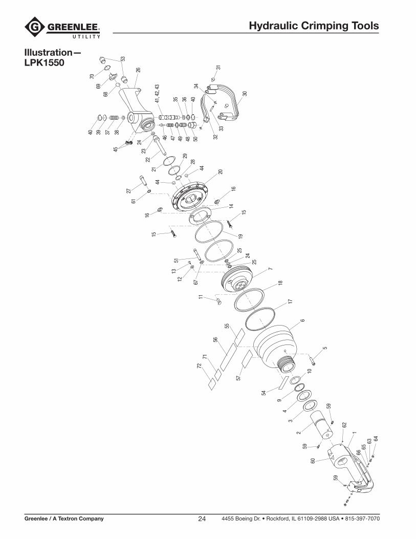
Illustration— LPK1550
2
60
34
9
54
6
11
12 67
1351
2761
40 39 37 38
22
45
10
5
17
18
7
2524
2530
32
34
3133
28
26
41, 4
2, 4
3
35 36 40
4746 504849
56
7172
5520
14
29
44
16
151915
16
44
2423
21
57
53
68
7069
59
59
1
62
59
6665
63 64
Hydraulic Crimping Tools
Greenlee / A Textron Company 4455 Boeing Dr. • Rockford, IL 61109-2988 USA • 815-397-707025
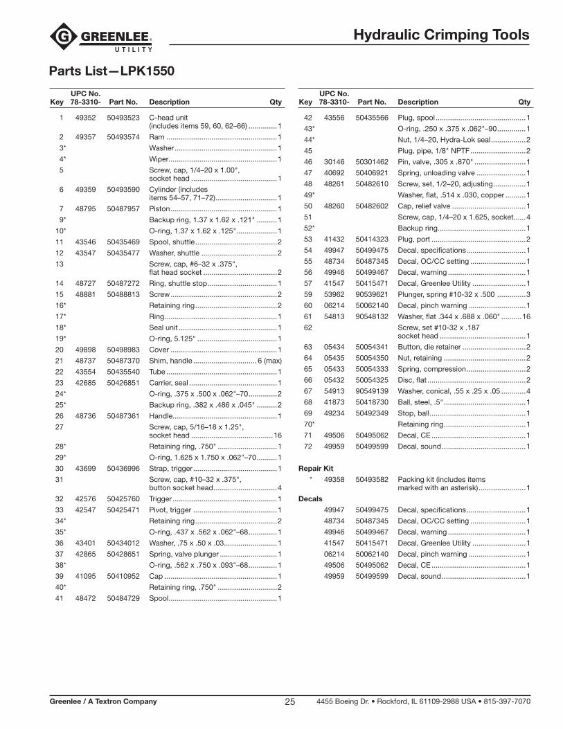
Parts List—LPK1550
UPC No. Key 78-3310- Part No. Description Qty
1 49352 50493523 C-head unit (includes items 59, 60, 62–66) ..............1
2 49357 50493574 Ram ......................................................1
3* Washer ..................................................1
4* Wiper .....................................................1
5 Screw, cap, 1/4–20 x 1.00", socket head ..........................................1
6 49359 50493590 Cylinder (includes items 54–57, 71–72) ..............................1
7 48795 50487957 Piston ....................................................1
9* Backup ring, 1.37 x 1.62 x .121" ..........1
10* O-ring, 1.37 x 1.62 x .125"....................1
11 43546 50435469 Spool, shuttle ........................................2
12 43547 50435477 Washer, shuttle .....................................2
13 Screw, cap, #6–32 x .375", flat head socket ....................................2
14 48727 50487272 Ring, shuttle stop ..................................1
15 48881 50488813 Screw ....................................................2
16* Retaining ring ........................................2
17* Ring .......................................................1
18* Seal unit ................................................1
19* O-ring, 5.125" .......................................1
20 49898 50498983 Cover ....................................................1
21 48737 50487370 Shim, handle ............................... 6 (max)
22 43554 50435540 Tube ......................................................1
23 42685 50426851 Carrier, seal ...........................................1
24* O-ring, .375 x .500 x .062"–70 ..............2
25* Backup ring, .382 x .486 x .045" ..........2
26 48736 50487361 Handle ...................................................1
27 Screw, cap, 5/16–18 x 1.25", socket head ........................................16
28* Retaining ring, .750" .............................1
29* O-ring, 1.625 x 1.750 x .062"–70 ..........1
30 43699 50436996 Strap, trigger .........................................1
31 Screw, cap, #10–32 x .375", button socket head ...............................4
32 42576 50425760 Trigger ...................................................1
33 42547 50425471 Pivot, trigger .........................................1
34* Retaining ring ........................................2
35* O-ring, .437 x .562 x .062"–68 ..............1
36 43401 50434012 Washer, .75 x .50 x .03..........................1
37 42865 50428651 Spring, valve plunger ............................1
38* O-ring, .562 x .750 x .093"–68 ..............1
39 41095 50410952 Cap .......................................................1
40* Retaining ring, .750" .............................2
41 48472 50484729 Spool .....................................................1
UPC No. Key 78-3310- Part No. Description Qty
42 43556 50435566 Plug, spool ............................................1
43* O-ring, .250 x .375 x .062"–90 ..............1
44* Nut, 1/4–20, Hydra-Lok seal .................2
45 Plug, pipe, 1/8" NPTF ...........................2
46 30146 50301462 Pin, valve, .305 x .870" .........................1
47 40692 50406921 Spring, unloading valve ........................1
48 48261 50482610 Screw, set, 1/2–20, adjusting ................1
49* Washer, flat, .514 x .030, copper ..........1
50 48260 50482602 Cap, relief valve ....................................1
51 Screw, cap, 1/4–20 x 1.625, socket ......4
52* Backup ring ...........................................1
53 41432 50414323 Plug, port ..............................................2
54 49947 50499475 Decal, specifications .............................1
55 48734 50487345 Decal, OC/CC setting ...........................1
56 49946 50499467 Decal, warning ......................................1
57 41547 50415471 Decal, Greenlee Utility ..........................1
59 53962 90539621 Plunger, spring #10-32 x .500 ..............3
60 06214 50062140 Decal, pinch warning ............................1
61 54813 90548132 Washer, flat .344 x .688 x .060" ..........16
62 Screw, set #10-32 x .187 socket head ..........................................1
63 05434 50054341 Button, die retainer ...............................2
64 05435 50054350 Nut, retaining ........................................2
65 05433 50054333 Spring, compression .............................2
66 05432 50054325 Disc, flat ................................................2
67 54913 90549139 Washer, conical, .55 x .25 x .05 ............4
68 41873 50418730 Ball, steel, .5" ........................................1
69 49234 50492349 Stop, ball ...............................................1
70* Retaining ring ........................................1
71 49506 50495062 Decal, CE ..............................................1
72 49959 50499599 Decal, sound .........................................1
Repair Kit
* 49358 50493582 Packing kit (includes items marked with an asterisk) .......................1
Decals
49947 50499475 Decal, specifications .............................1
48734 50487345 Decal, OC/CC setting ...........................1
49946 50499467 Decal, warning ......................................1
41547 50415471 Decal, Greenlee Utility ..........................1
06214 50062140 Decal, pinch warning ............................1
49506 50495062 Decal, CE ..............................................1
49959 50499599 Decal, sound .........................................1
Hydraulic Crimping Tools
Greenlee / A Textron Company 4455 Boeing Dr. • Rockford, IL 61109-2988 USA • 815-397-707026
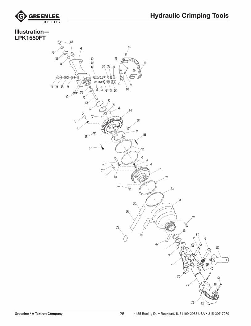
Illustration— LPK1550FT
49
54
6
11
12 67
1351
2761
40 39 37 38
22
45
10
5
17
18
7
2524
2530
32
34
3133
28
26
41, 4
2, 4
3
35 36 40
4746 504849
56
72
5520
14
29
44
16
151915
16
44
2423
21
57
53
68
7069
2
1
75
7360
7978
7475
77
76
8381
80
82
Hydraulic Crimping Tools
Greenlee / A Textron Company 4455 Boeing Dr. • Rockford, IL 61109-2988 USA • 815-397-707027
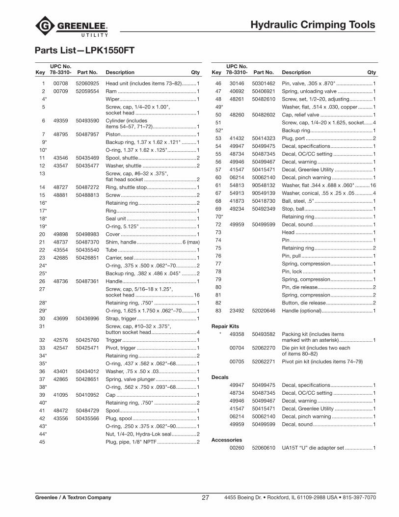
Parts List—LPK1550FT
UPC No. Key 78-3310- Part No. Description Qty
1 00708 52060925 Head unit (includes items 73–82) ..........1
2 00709 52059554 Ram ......................................................1
4* Wiper .....................................................1
5 Screw, cap, 1/4–20 x 1.00", socket head ..........................................1
6 49359 50493590 Cylinder (includes items 54–57, 71–72) ..............................1
7 48795 50487957 Piston ....................................................1
9* Backup ring, 1.37 x 1.62 x .121" ..........1
10* O-ring, 1.37 x 1.62 x .125"....................1
11 43546 50435469 Spool, shuttle ........................................2
12 43547 50435477 Washer, shuttle .....................................2
13 Screw, cap, #6–32 x .375", flat head socket ....................................2
14 48727 50487272 Ring, shuttle stop ..................................1
15 48881 50488813 Screw ....................................................2
16* Retaining ring ........................................2
17* Ring .......................................................1
18* Seal unit ................................................1
19* O-ring, 5.125" .......................................1
20 49898 50498983 Cover ....................................................1
21 48737 50487370 Shim, handle ............................... 6 (max)
22 43554 50435540 Tube ......................................................1
23 42685 50426851 Carrier, seal ...........................................1
24* O-ring, .375 x .500 x .062"–70 ..............2
25* Backup ring, .382 x .486 x .045" ..........2
26 48736 50487361 Handle ...................................................1
27 Screw, cap, 5/16–18 x 1.25", socket head ........................................16
28* Retaining ring, .750" .............................1
29* O-ring, 1.625 x 1.750 x .062"–70 ..........1
30 43699 50436996 Strap, trigger .........................................1
31 Screw, cap, #10–32 x .375", button socket head ...............................4
32 42576 50425760 Trigger ...................................................1
33 42547 50425471 Pivot, trigger .........................................1
34* Retaining ring ........................................2
35* O-ring, .437 x .562 x .062"–68 ..............1
36 43401 50434012 Washer, .75 x .50 x .03..........................1
37 42865 50428651 Spring, valve plunger ............................1
38* O-ring, .562 x .750 x .093"–68 ..............1
39 41095 50410952 Cap .......................................................1
40* Retaining ring, .750" .............................2
41 48472 50484729 Spool .....................................................1
42 43556 50435566 Plug, spool ............................................1
43* O-ring, .250 x .375 x .062"–90 ..............1
44* Nut, 1/4–20, Hydra-Lok seal .................2
45 Plug, pipe, 1/8" NPTF ...........................2
UPC No. Key 78-3310- Part No. Description Qty
46 30146 50301462 Pin, valve, .305 x .870" .........................1
47 40692 50406921 Spring, unloading valve ........................1
48 48261 50482610 Screw, set, 1/2–20, adjusting ................1
49* Washer, flat, .514 x .030, copper ..........1
50 48260 50482602 Cap, relief valve ....................................1
51 Screw, cap, 1/4–20 x 1.625, socket ......4
52* Backup ring ...........................................1
53 41432 50414323 Plug, port ..............................................2
54 49947 50499475 Decal, specifications .............................1
55 48734 50487345 Decal, OC/CC setting ...........................1
56 49946 50499467 Decal, warning ......................................1
57 41547 50415471 Decal, Greenlee Utility ..........................1
60 06214 50062140 Decal, pinch warning ............................1
61 54813 90548132 Washer, flat .344 x .688 x .060" ..........16
67 54913 90549139 Washer, conical, .55 x .25 x .05 ............4
68 41873 50418730 Ball, steel, .5" ........................................1
69 49234 50492349 Stop, ball ...............................................1
70* Retaining ring ........................................1
72 49959 50499599 Decal, sound .........................................1
73 Head .....................................................1
74 Pin .........................................................1
75 Retaining ring ........................................2
76 Pin, pull .................................................1
77 Spring, compression .............................1
78 Pin, lock ................................................1
79 Spring, compression .............................1
80 Pin, die release......................................2
81 Spring, compression .............................2
82 Button, die release ................................2
83 23492 52020646 Handle (optional) ...................................1
Repair Kits
* 49358 50493582 Packing kit (includes items marked with an asterisk) .......................1
00704 52062270 Die pin kit (includes two each of items 80–82)
00705 52062271 Pivot pin kit (includes items 74–79)
Decals
49947 50499475 Decal, specifications .............................1
48734 50487345 Decal, OC/CC setting ...........................1
49946 50499467 Decal, warning ......................................1
41547 50415471 Decal, Greenlee Utility ..........................1
06214 50062140 Decal, pinch warning ............................1
49959 50499599 Decal, sound .........................................1
Accessories
00260 52060610 UA15T “U” die adapter set ...................1

4455 Boeing Drive • Rockford, IL 61109-2988 • USA • 815-397-7070An ISO 9001 Company • Greenlee Textron Inc. is a subsidiary of Textron Inc.
USA Tel: 800-435-0786 Fax: 800-451-2632
Canada Tel: 800-435-0786 Fax: 800-524-2853
International Tel: +1-815-397-7070 Fax: +1-815-397-9247
www.greenlee.com