hydraulic accumulators with back-up nitrogen bottles
TRANSCRIPT
107
EN 3
.553
.6/0
4.21
Hydraulic accumulators with back-up nitrogen bottles
1. GENERALTo complete the accumulator range, HYDAC provides a variety of useful accessory products. They guarantee correct installation and optimum functioning of HYDAC hydraulic accumulators. They include nitrogen bottles which can be used to back up bladder and piston accumulators. Nitrogen bottles used as back-ups increase the gas volume in the accumulator system. This means that smaller accumulators can be used for the same gas volume and costs can be reduced. For further information, please turn to the sections:
zBladder accumulators Standard design No. 3.201 zPiston accumulators Standard design No. 3.301
1.1. NOTICEAll work with HYDAC hydraulic accumulators / nitrogen bottles must only be carried out by suitably trained staff.Incorrect installation or handling can lead to serious accidents. The operating instructions must be observed!
zOperating instructions for bladder accumulators SB No. 3.201.BA zOperating instructions for piston accumulators SK No. 3.301.BA zOperating instructions for gas pressure vessels GDB No. 3.553.BA
Further information such as accumulator sizing, safety information and extracts from the acceptance specifications can be found in the following catalogue section:
zHYDAC Accumulator Technology No. 3.000
Relevant PDF documents can be accessed at: www.hydac.com » Downloads » Documents » Accumulator Division
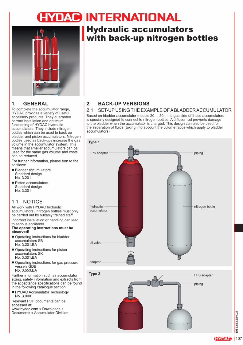
2. BACK-UP VERSIONS2.1. SET-UP USING THE EXAMPLE OF A BLADDER ACCUMULATORBased on bladder accumulator models 20 ... 50 l, the gas side of these accumulators is specially designed to connect to nitrogen bottles. A diffuser rod prevents damage to the bladder when the accumulator is charged. This design can also be used for the separation of fluids (taking into account the volume ratios which apply to bladder accumulators).
FPS adapter
piping
FPS adapter
piping
nitrogen bottlehydraulic accumulator
oil valve
adapter
Type 2
Type 1

108
EN 3
.553
.6/0
4.21
Type 1
2.2. DIMENSIONS
Type 2
2.3. SPARE PARTSNBR, carbon steel, standard gas valve
Nominal volume of accum.
Seal kit Repair kitType 1 Type 2
[l] Part no. Part no. Part no.20
353621
3119500 389746424 3119502 389746332 3119498 389746250 3119499 3897461
Description ItemBladder assembly consisting of:
Bladder 2Lock nut 4Diffuser rod 30O-ring 22x2.5 1) 31Adapter for type 1/2 32
Seal kit consisting of:
O-ring 7.5x2 1) 7Washer 15O-ring 80x5 1) 16Seal ring 20Support ring 23O-ring 48x3 1) 27
Repair kit consisting of:
Bladder assembly (see above)Seal kit (see above)O-ring 11x2 1) 33
Anti-extrusion ring 14FPS adapter for type 1/2 2) 34
Recommended spare parts1) Different dimensions for code 663 and 6652) FPS adapter (item 34) available as an accessory,
see section 4.2.Accumulator shell (item 1) not available as a spare partAdapter (item 25) incl. O-ring (item 27) available as an accessory, see catalogue section: Bladder accumulators, Standard design No. 3.201, section 4.Adapter (item 32) for type 1 standardFor other spare parts, see section 3.
Nominal volume [l]
Effect. gas volume [l]
Weight [kg]
A max. [mm]
Part no.
Type 1 Type 2
20 17.5 53.5 905 3153006 323933424 24 72 1070 3280349 448131632 32.5 89 1420 3114824 308583850 47.5 119.5 1930 3079661 3082402
Others on request

109
EN 3
.553
.6/0
4.21
3.3. SPECIFICATIONS3.3.1 Model code Not all combinations are possible. Order example. For further information, please contact HYDAC.
SN360 - 50 AA / 010 U - 360 D G - C
Series
Code No details = standard Special types (see section 3.1.)
Nominal volume [l]
Connection type
Type on drain side (condensate) A = ISO 228 (BSP) B = DIN 13 to ISO 965/1 (metric) C = ANSI B1.1 (UNF seal SAE) D = ANSI B2.1 F = flange
Type on connection side A = ISO 228 (BSP) B = DIN 13 to ISO 965/1 (metric) C = ANSI B1.1 (UNF seal SAE) D = ANSI B2.1 F = flange
Material code (MC)
Material (connection) 0 = no installed parts 1 = carbon steel 3 = stainless steel 1) 4 = carbon steel with protective coating 6 = low temperature steel
Housing material 1 = carbon steel 2 = carbon steel with protective coating 4 = stainless steel 1) 6 = low temperature steel
Seal material (elastomer) 0 = no elastomer used 2 = NBR 4 = IIR 5 = low temperature NBR 6 = FKM
Certification code U = European Pressure Equipment Directive (PED)
Permitted operating pressure [bar]
Size for drain side (see Table 3.3.3)
Size for connection side (see Table 3.3.3)
Version No details = standard C = compact
3. NITROGEN BOTTLES3.1. DESCRIPTION AND
DESIGN
HYDAC nitrogen bottles are used for receiving and storing nitrogen.HYDAC supplies various versions, such as standard nitrogen bottles made from forged vessels and special vessels based on bladder accumulator shells (SN...B), piston accumulator tubes (SN...K) and diaphragm accumulator halves (SN...M) – see catalogue sections:
zBladder accumulators Standard design No. 3.201 zPiston accumulators Standard design No. 3.301 zDiaphragm accumulators No. 3.100
The following technical specifications refer to standard nitrogen bottles. Please ask us for information regarding other designs.
3.2. ADVANTAGESUsing HYDAC nitrogen bottles provides the following advantages:
zCost-effective increase in the accumulator volume and z smaller accumulators for the same gas volume as a result.
nitrogen bottle
connection side
drain side e.g. with condensate drain
1) Dependent on type and pressure rating

110
EN 3
.553
.6/0
4.21
3.3.2 DimensionsVersion: standard Version: compact
Series
Volu
me Version
Cer
tifica
tion
code Connections to
ISO 228 (Type AA)A ±25
D ±1 %
Weight approx.
Part no. Designation
Drain side
Connec-tion side
[l] [mm] [mm] [kg]SN360
50 StandardU
G 3/4 G 3/41590 229 89
3176324 SN360-50AA/010U-360DDG 3/4 G 1 1/2 3418347 SN360-50AA/010U-360DG
S G 3/4 G 1 1/2 3987605 SN360-50AA/010S-210DG
75Standard
U G 3/4 G 1 1/22280 229 126
3561595 SN360-75AA/010U-360DGS G 3/4 G 1 1/2 3987606 SN360-75AA/010S-210DG
CompactU G 3/4 G 1 1/2
1690 273 1243987162 SN360-75AA/010U-360DG-C
S G 3/4 G 1 1/2 3987163 SN360-75AA/010S-200DG-CSN600 50 Standard S G 3/4 G 1 1/2 1730 241 143 3987613 SN600-50AA/010S-345DG
75 Standard S G 3/4 G 1 1/2 2500 232 197 3987614 SN600-75AA/010S-345DG
3.3.3 Connections for SN360The following connections are available for standard nitrogen bottles (see section 3.3.2). Standard connections are highlighted in grey. All other versions available on request (not all combinations are possible).
Type
Size
A BSP ISO228
B Metric DIN13 ISO965/1
C SAE ANSI B1.1
D NPT ANSI B2.1
F Flange connection
A G 1/4" M12x1.5 7/16"-20UNF 1/4" 1/2" 3000 psi, code 61
B G 3/8" M18x1.5 9/16"-18UNF 3/8" 3/4"C G 1/2" M22x1.5 3/4"-16UNF 1/2" 1"D G 3/4" M27x2 1 1/16"-12UN 3/4" 1 1/4"E G 1" M33x2 1 5/16"-12UN 1" 1 1/2"F G 1 1/4" M42x2 1 5/8"-12UN 1 1/4" 2"
G G 1 1/2" M48x2 1 7/8"-12UN 1 1/2" 1/2" 6000 psi, code 62
H G 2" M14x1.5 2 1/2"-12UN 2" 3/4"I G 1 3/4" M8 - - -K - M16x1.5 - - 1 1/4"L - - 7/8"-14UNF 5/8" 1 1/2"M - - - - 2"S Special design

111
EN 3
.553
.6/0
4.21
4. ACCESSORIES4.1. F + P CHARGING AND TESTING BLOCK 4.1.1 DescriptionThe HYDAC F + P charging and testing block is used to charge and test back-up type hydraulic accumulators. It has connections for the FPU-1 charging and testing unit and for pressure gauges. As a safety function, a GSV6 gas safety valve can be fitted (see catalogue section given below). In addition, it allows the back-up nitrogen bottles to be shut off from the hydraulic accumulator.
z Safety equipment for hydraulic accumulators No. 3.552
4.1.2 Hydraulic circuit with charging and testing block
nitrogen bottles
hydraulic accumulator
safety and shut-off block
charging and testing block
connection for gas safety valve
connection for FPU-1 charging and testing unit *
* For further information, see catalogue section:• FPU charging and testing unit
No. 3.501
Carbon steel, NBR
Designation Max. operating pressure [bar]
Weight [kg]
Part no. Seal kit 1) Fig.
F+P-16-20SR-6112-02X 400 4.3 850233 2115776 1
F+P-32-38SR-6112-02X 350 14 552193 2112088 1
F+P-32-38SR-6112-12X-A-GSV-MV 350 21.4 4241832 2112088 21) Recommended spare parts
4.1.3 Preferred models / spare parts
Figure 1 Figure 2

112
EN 3
.553
.6/0
4.21
4.1.4 Technical data/dimensions Charging and testing block DN 16
charging and testing unitM28x1.5
4 mountingbores
hydraulic accumulator
nitrogen bottle
gas safety valveGSV6 (optional)
AF41
pressure gauge connection(optional)
pressure gauge connection(optional)
Charging and testing block DN 32
charging and testing unitM28x1.5 4 mounting
bores
hydraulic accumulator
nitrogen bottle
gas safety valveGSV6 (optional)
pressure gauge connection(optional)
pressure gauge connection(optional)
AF12
AF17
AF41

113
EN 3
.553
.6/0
4.21
4.3. NITROGEN CHARGING UNIT
HYDAC nitrogen charging units make it possible to rapidly and inexpensively charge or test the required gas pre-charge pressures in bladder, piston and diaphragm accumulators. They guarantee an optimal utilisation of standard commercial nitrogen bottles up to a residual pressure of 20 bar and a maximum pre-charge pressure of 350 bar. Portable, mobile and stationary N2-Server versions are available. For further information and technical data, see the following brochure:
zNitrogen charging units N2-Server No. 2.201
Higher pressures available on request.
HYDAC Technology GmbH Industriegebiet 66280 Sulzbach/Saar, Germany Tel.: +49 (0) 68 97 / 509 - 01 Fax: +49 (0) 68 97 / 509 - 464 Internet: www.hydac.com E-mail: [email protected]
4.3. CONDENSATE DRAIN SETThe condensate drain set consists of a throttle valve and a suitable condensate draining hose. It is used to drain any condensate from the nitrogen bottle, in a controlled way.
4.2. FPS ADAPTERThe HYDAC FPS adapter is used to charge back-up type hydraulic accumulator systems. For this purpose, it has a connection for the FPU-1 charging and testing unit.
Designation G ISO 228
Part no. Type
Adapter FPS 7/8-14UNF G 3/4 363226 1Adapter FPS G 3/4 243218 2
nitrogen bottle
condensate drain
draining hose
throttle valve
Designation Length [m] Part no.Condensate drain G 3/4 – Minimess M16x1.5 – 3219496
Condensate drain set0.4 34728201 34728231.6 3472824
FPS adapter for type 1 FPS adapter for type 2
condensate drain set
5. NOTEThe information in this brochure relates to the operating conditions and fields of application described. For applications and/or operating conditions not described, please contact the relevant technical department. Subject to technical modifications.

114
EN 3
.553
.6/0
4.21