hydrascan configuration software - user guide
TRANSCRIPT
Part of Thermo Fisher Scientific
HydraScanConfiguration Software for Thermo Scientific Doppler FlowmetersUser GuideP/N 1-0563-005
Revision B


HydraScanConfiguration Software for Thermo Scientific Doppler FlowmetersUser GuideP/N 1-0563-005
Revision B


©2003 Thermo Fisher Scientific Inc. All rights reserved.
“Windows” is either a registered trademark or trademark of Microsoft Corporation in the United States and/or other countries.
All other trademarks are the property of Thermo Fisher Scientific Inc. and its subsidiaries.
Disclaimer: Thermo Fisher Scientific (Thermo Fisher) makes every effort to ensure the accuracy and completeness of this guide. However, we cannot be responsible for errors, omissions, or any loss of data resulting from errors or omissions. Thermo Fisher reserves the right to make changes to the guide or improvement to the product at any time without notice. The material in this guide is proprietary and cannot be reproduced in any form without expressed written consent from Thermo Fisher.

This page intentionally left blank.

TABLE OF CONTENTS
1. Product Overview ................................................................................................................................. 1
2. Initializing HydraScan .......................................................................................................................... 22.1 Installing HydraScan ......................................................................................................................... 22.2 Starting the Meter ............................................................................................................................. 22.3 Opening HydraScan ......................................................................................................................... 2
3. Configuring the Flowmeter .................................................................................................................. 53.1 Obtaining Pipe Inside Diameter ........................................................................................................ 53.2 Entering Pipe Parameters ................................................................................................................. 63.3 Entering Other Application Information ............................................................................................. 6
3.3.1 Low Flow Cutoff .......................................................................................................................... 63.3.2 Damping ...................................................................................................................................... 73.3.3 Flow Conversion Factor .............................................................................................................. 73.3.4 Velocity Cutoff ............................................................................................................................. 73.3.5 Site Calibration ............................................................................................................................ 73.3.6 Remote Zero ............................................................................................................................... 7
3.4 The Totalizer ..................................................................................................................................... 83.4.1 The Totalizer Value ..................................................................................................................... 83.4.2 Setting Totalizer Units ................................................................................................................. 83.4.3 Resetting the Totalizer ................................................................................................................ 83.4.4 Enabling the Totalizer Relay ........................................................................................................ 8
3.4.4.a For the Hydra SX50 ............................................................................................................... 83.4.4.b For the Hydra SX40................................................................................................................. 9
3.5 Customizing the Hydra SX50 Meter Display ..................................................................................... 9
4. Output Options ................................................................................................................................... 104.1 Setting Up the 4-20 mA Loop .......................................................................................................... 104.2 Calibrating the 4-20 mA .................................................................................................................. 114.3 The Relay ....................................................................................................................................... 13
4.3.1 Testing the Relay ...................................................................................................................... 134.3.2 Setting Up the Relay ................................................................................................................. 13
5. The Limits Page .................................................................................................................................. 155.1 Setting the Time & Date .................................................................................................................. 155.2 The Datalogger ............................................................................................................................... 16
5.2.1 Setting Up the Datalogger ......................................................................................................... 165.2.2 Using HydraLink with the Datalogger ........................................................................................ 165.2.3 Opening Saved Log Files .......................................................................................................... 165.2.4 Saving Log Files ........................................................................................................................ 165.2.5 Erasing Log Files....................................................................................................................... 185.2.6 Zooming in on Data ................................................................................................................... 19
5.3 The Lost Power Feature ................................................................................................................. 205.3.1 The Power Monitor Relay .......................................................................................................... 205.3.2 Resetting the Power Monitor ..................................................................................................... 21
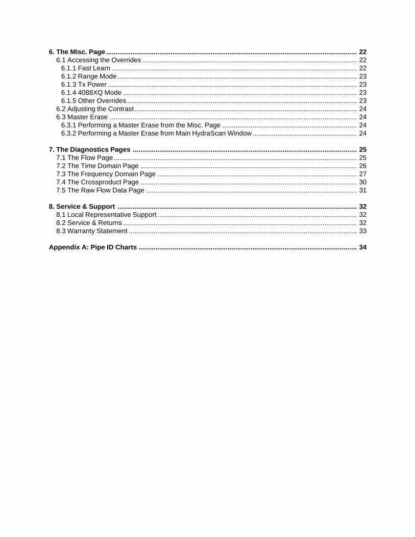
6. The Misc. Page .................................................................................................................................... 226.1 Accessing the Overrides ................................................................................................................. 22
6.1.1 Fast Learn ................................................................................................................................. 226.1.2 Range Mode .............................................................................................................................. 236.1.3 Tx Power ................................................................................................................................... 236.1.4 4088XQ Mode ........................................................................................................................... 236.1.5 Other Overrides ......................................................................................................................... 23
6.2 Adjusting the Contrast ..................................................................................................................... 246.3 Master Erase .................................................................................................................................. 24
6.3.1 Performing a Master Erase from the Misc. Page ....................................................................... 246.3.2 Performing a Master Erase from Main HydraScan Window ....................................................... 24
7. The Diagnostics Pages ...................................................................................................................... 257.1 The Flow Page................................................................................................................................ 257.2 The Time Domain Page .................................................................................................................. 267.3 The Frequency Domain Page ......................................................................................................... 277.4 The Crossproduct Page .................................................................................................................. 307.5 The Raw Flow Data Page ............................................................................................................... 31
8. Service & Support .............................................................................................................................. 328.1 Local Representative Support ......................................................................................................... 328.2 Service & Returns ........................................................................................................................... 328.3 Warranty Statement ........................................................................................................................ 33
Appendix A: Pipe ID Charts ................................................................................................................... 34

1
1. PRODUCT OVERVIEW
The HydraScan software is a PC-based program that interfaces with the Hydra SX series of flowmeters.The software’s on-line functions allow the user to perform system configurations, view flowmeter capabili-ties, view and edit system parameters, and collect historical data.
This manual was written utilizing the Hydra SX50. Note that not all functions/features apply to each Hydramodel, and a particular function/feature may vary slightly from one model to another. Also note that if youare operating the Hydra SX30 or SX40, the software screens may vary slightly from the screens used inthis manual.

This page intentionally left blank.

2
2. INITIALIZING HYDRASCAN
2.1 Installing HydraScan
1. Insert the PolyCD into the drive.
2. Click the Start button on the bottom left corner of your desktop, and select Run.
3. Click Browse, and select the CD drive.
4. Select Setup.exe.
5. Click OK, and follow the directions as they appear on the screen.
6. After installing the PolyCD, click the Start button on the bottom left corner of your desktop.
7. Click Programs, and select PolyCD.
8. Click OK on the opening screen.
9. Select Run from CD on the following screen.
10. Select Communications Software.
11. Select HydraScan, and follow the instructions as they appear on the screen.
12. After completing the installation, click Exit.
13. Click Exit on the following screen.
2.2 Starting the Meter
1. Ensure there is flow in the pipe.
2. Apply power to the meter.
2.3 Opening HydraScan
1. Connect the communication cable from the flowmeter to the RS232 port on the computer.
2. Click the Start button on the bottom left corner of your desktop, and select Programs.
3. Select HydraScan.
3
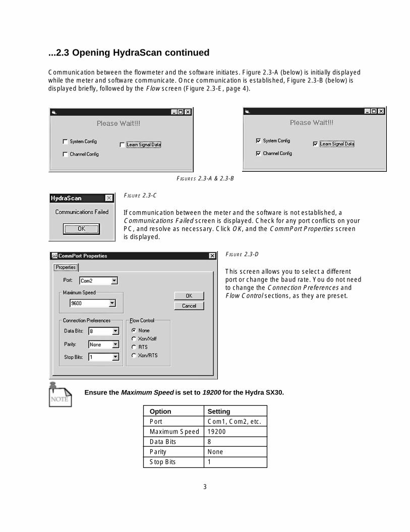
...2.3 Opening HydraScan continued
Communication between the flowmeter and the software initiates. Figure 2.3-A (below) is initially displayedwhile the meter and software communicate. Once communication is established, Figure 2.3-B (below) isdisplayed briefly, followed by the Flow screen (Figure 2.3-E, page 4).
FIGURES 2.3-A & 2.3-B
FIGURE 2.3-C
If communication between the meter and the software is not established, aCommunications Failed screen is displayed. Check for any port conflicts on yourPC, and resolve as necessary. Click OK, and the CommPort Properties screenis displayed.
FIGURE 2.3-D
This screen allows you to select a differentport or change the baud rate. You do not needto change the Connection Preferences andFlow Control sections, as they are preset.
Ensure the Maximum Speed is set to 19200 for the Hydra SX30.
Option Setting
Port Com1, Com2, etc.
Maximum Speed 19200
Data Bits 8
Parity None
Stop Bits 1

4
FIGURE 2.3-E
����� If operating the Hydra SX30 or SX40, the appropriate meter name will appear in the top leftcorner as well as on the Setup button (SX30 Setup, SX40 Setup).
When all the properties information is correct, click OK, and Figure 2.3-A (above) is initially displayed whilethe meter and software communicate. Once communication is established, Figure 2.3-B (page 3) isdisplayed briefly, followed by the Flow screen (Figure 2.3-E, above).
You are now ready to configure the meter.

This page intentionally left blank.
5
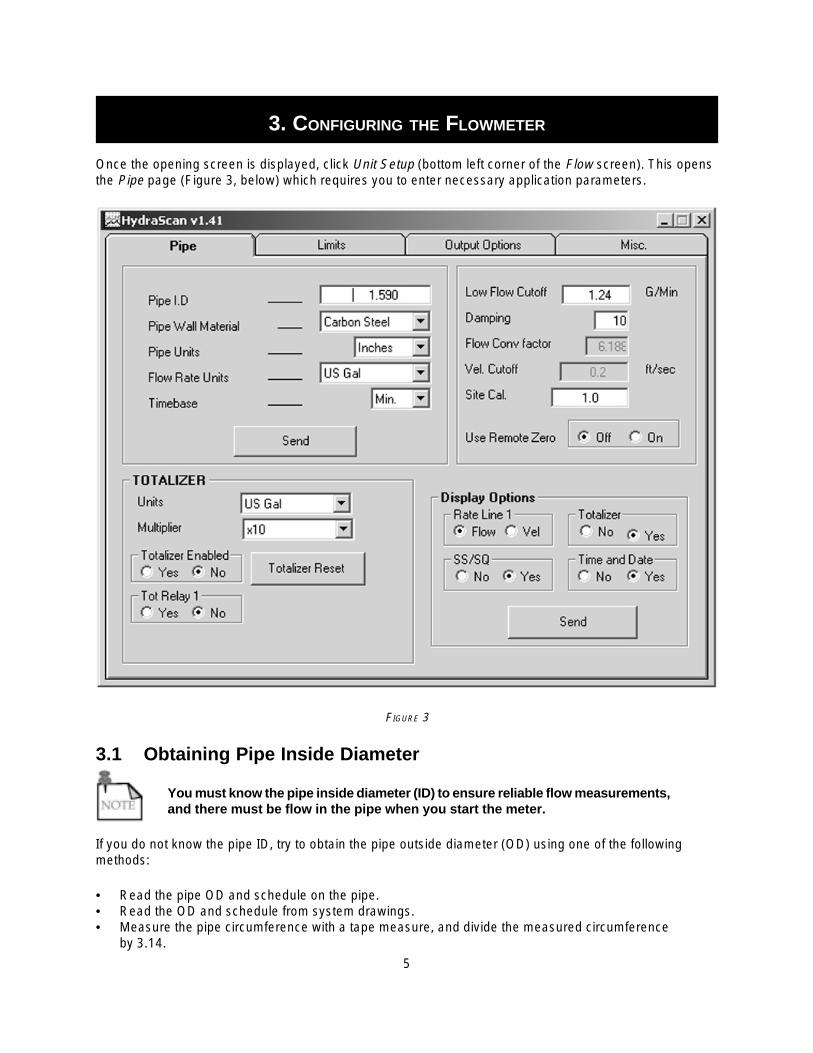
3. CONFIGURING THE FLOWMETER
Once the opening screen is displayed, click Unit Setup (bottom left corner of the Flow screen). This opensthe Pipe page (Figure 3, below) which requires you to enter necessary application parameters.
FIGURE 3
3.1 Obtaining Pipe Inside Diameter
You must know the pipe inside diameter (ID) to ensure reliable flow measurements,and there must be flow in the pipe when you start the meter.
If you do not know the pipe ID, try to obtain the pipe outside diameter (OD) using one of the followingmethods:
• Read the pipe OD and schedule on the pipe.• Read the OD and schedule from system drawings.• Measure the pipe circumference with a tape measure, and divide the measured circumference
by 3.14.
6
...3.1 Obtaining Pipe Inside Diameter continued
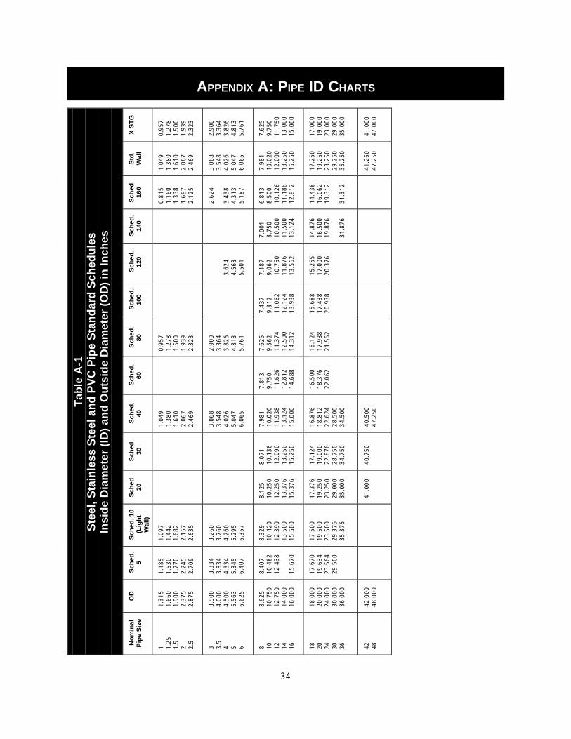
Use the OD with the charts in Appendix A: Pipe ID Charts (pages 34-36) to obtain an approximate pipe ID.
For a more accurate pipe ID use Thermo Fisher’s Ultrasonic Pipe Thickness Gauge (part number 0704-0187),and perform the following calculation:
pipe ID = pipe OD – (2 x pipe thickness).
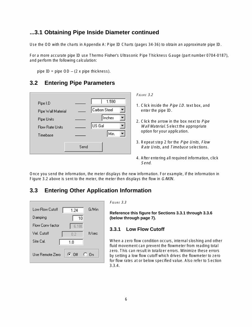
3.2 Entering Pipe Parameters
FIGURE 3.2
1. Click inside the Pipe I.D. text box, andenter the pipe ID.
2. Click the arrow in the box next to PipeWall Material. Select the appropriateoption for your application.
3. Repeat step 2 for the Pipe Units, FlowRate Units, and Timebase selections.
4. After entering all required information, clickSend.
Once you send the information, the meter displays the new information. For example, if the information inFigure 3.2 above is sent to the meter, the meter then displays the flow in G/MIN.
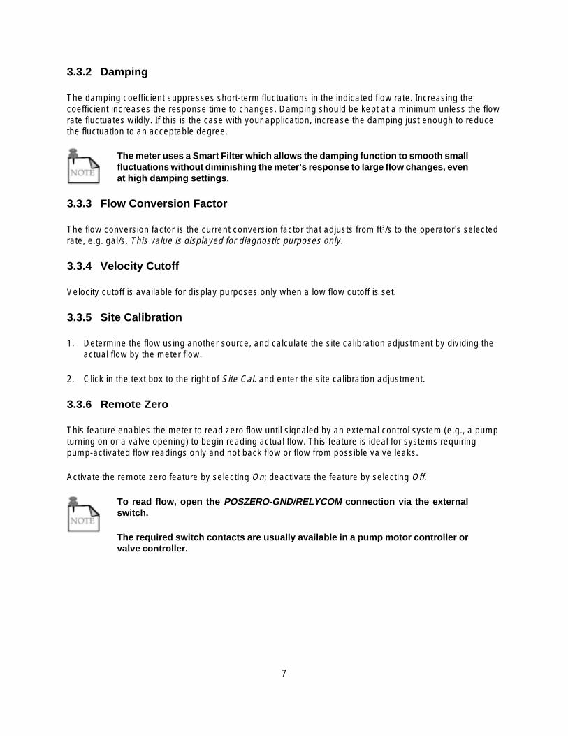
3.3 Entering Other Application Information
FIGURE 3.3
Reference this figure for Sections 3.3.1 through 3.3.6(below through page 7).
3.3.1 Low Flow Cutoff
When a zero flow condition occurs, internal sloshing and otherfluid movement can prevent the flowmeter from reading totalzero. This can result in totalizer errors. Minimize these errorsby setting a low flow cutoff which drives the flowmeter to zerofor flow rates at or below specified value. Also refer to Section3.3.4.
7
3.3.2 Damping
The damping coefficient suppresses short-term fluctuations in the indicated flow rate. Increasing thecoefficient increases the response time to changes. Damping should be kept at a minimum unless the flowrate fluctuates wildly. If this is the case with your application, increase the damping just enough to reducethe fluctuation to an acceptable degree.
The meter uses a Smart Filter which allows the damping function to smooth smallfluctuations without diminishing the meter’s response to large flow changes, evenat high damping settings.
3.3.3 Flow Conversion Factor
The flow conversion factor is the current conversion factor that adjusts from ft3/s to the operator’s selectedrate, e.g. gal/s. This value is displayed for diagnostic purposes only.
3.3.4 Velocity Cutoff
Velocity cutoff is available for display purposes only when a low flow cutoff is set.
3.3.5 Site Calibration
1. Determine the flow using another source, and calculate the site calibration adjustment by dividing theactual flow by the meter flow.
2. Click in the text box to the right of Site Cal. and enter the site calibration adjustment.
3.3.6 Remote Zero
This feature enables the meter to read zero flow until signaled by an external control system (e.g., a pumpturning on or a valve opening) to begin reading actual flow. This feature is ideal for systems requiringpump-activated flow readings only and not back flow or flow from possible valve leaks.
Activate the remote zero feature by selecting On; deactivate the feature by selecting Off.
To read flow, open the POSZERO-GND/RELYCOM connection via the externalswitch.
The required switch contacts are usually available in a pump motor controller orvalve controller.

8
3.4 The Totalizer
FIGURE 3.4-A
3.4.1 The Totalizer Value
This is the unit’s totalized value expressed in engi-neering units (selected by the operator).
3.4.2 Setting Totalizer Units
1. Set the totalizer units by clicking on the arrow forthe drop-down menu in the box to the right ofUnits.
2. Select the measurement unit required for your application.
3. Set the totalizer multiplier by clicking on the arrow for the drop-down menu in the box to the right ofMultiplier.
4. Select the appropriate multiplier option.
5. Locate the Totalizer Enabled section, and click in the circle to the left of Yes to start the totalizer.
Click in the circle to the left of No to disable the totalizer.
3.4.3 Resetting the Totalizer
FIGURE 3.4-B
1. Click the Reset button.
2. A warning appears. Click Yes to reset thetotalizer or No if you do not want to reset thetotalizer.
3.4.4 Enabling the Totalizer Relay
3.4.4.a For the Hydra SX50
1. From the SX50 Pipe page, locate the section labeled Tot Relay 1 (reference Figure 3.4-A, above).
2. Click in the circle to the left of Yes to enable the relay; click in the circle to the left of No to disable therelay.
If your application requires a totalizer output, connect the pulse totalized outputto the relay terminal block. If this is the case with your application, the alarm orset point relay is not available.
9
3.4.4.b For the Hydra SX40
This feature is designed to send a pulse each time a preset rate of total flow occurs.
The pulse totalizer multiplier is not independent of the totalizer multiplier.
While Totalizer Relay 1 is active, relay 1 cannot be configured/reconfigured.
1. From the SX40 Pipe page, locate Tot Relay 1.
2. To activate Totalizer Relay 1, click the arrow to the right of Tot Relay 1 to display the multiplier options.
3. Select the desired multiplier.
Deactivate Totalizer Relay 1 by selecting No in the Totaly Relay 1 box.
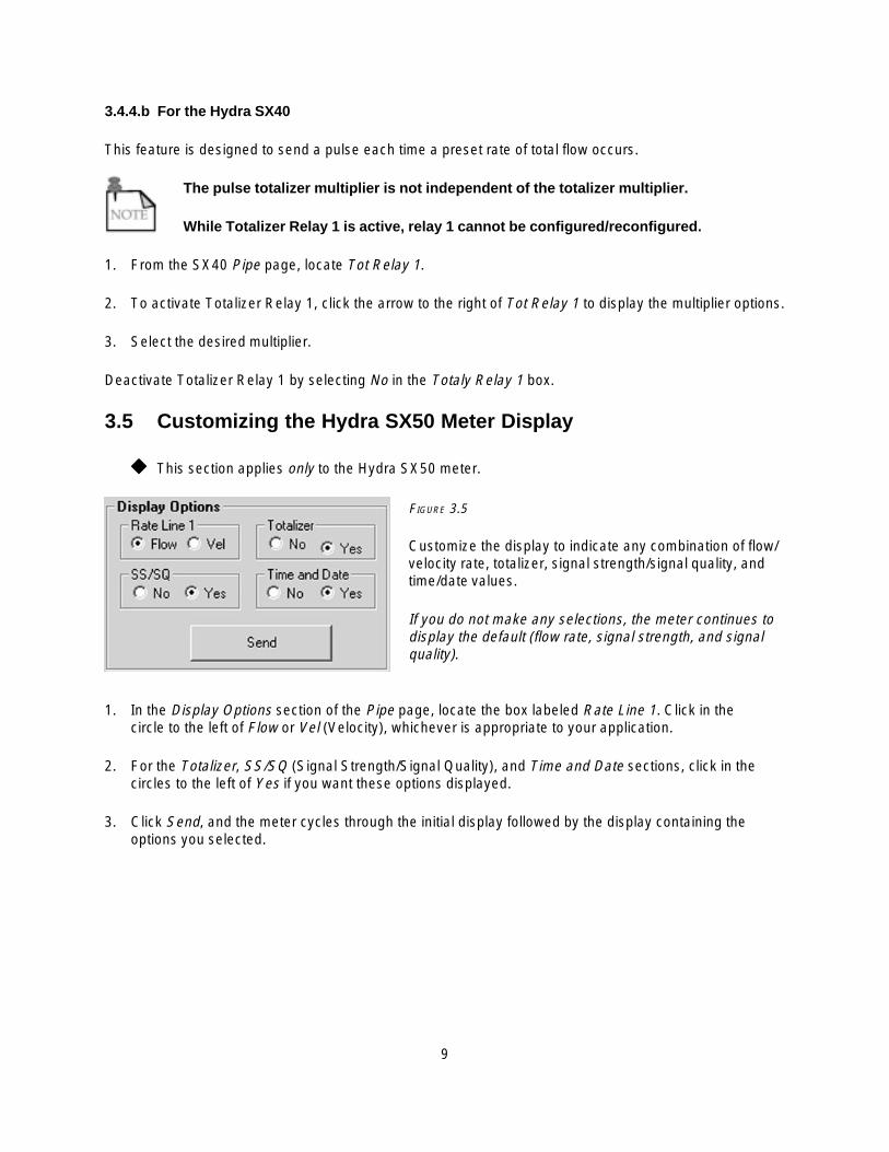
3.5 Customizing the Hydra SX50 Meter Display
����� This section applies only to the Hydra SX50 meter.
FIGURE 3.5
Customize the display to indicate any combination of flow/velocity rate, totalizer, signal strength/signal quality, andtime/date values.
If you do not make any selections, the meter continues todisplay the default (flow rate, signal strength, and signalquality).
1. In the Display Options section of the Pipe page, locate the box labeled Rate Line 1. Click in thecircle to the left of Flow or Vel (Velocity), whichever is appropriate to your application.
2. For the Totalizer, SS/SQ (Signal Strength/Signal Quality), and Time and Date sections, click in thecircles to the left of Yes if you want these options displayed.
3. Click Send, and the meter cycles through the initial display followed by the display containing theoptions you selected.

This page intentionally left blank.

10
4. OUTPUT OPTIONS
Go to the Output Options page to set up or calibrate the 4-20 mA and to set up or test the relay.
FIGURE 4
4.1 Setting Up 4-20 mA Loop
1. Click the check box to the right of 4-20mA Setup.
2. In the text box to the right of Flow Rate at 4 mA, enter the flow rate that equals the 4 mA (minimum)reading.
3. In the text box to the right of Flow Rate at 20 mA, enter the flow rate that equals the 20 mA (maximum)reading.
4. Click Send.
11
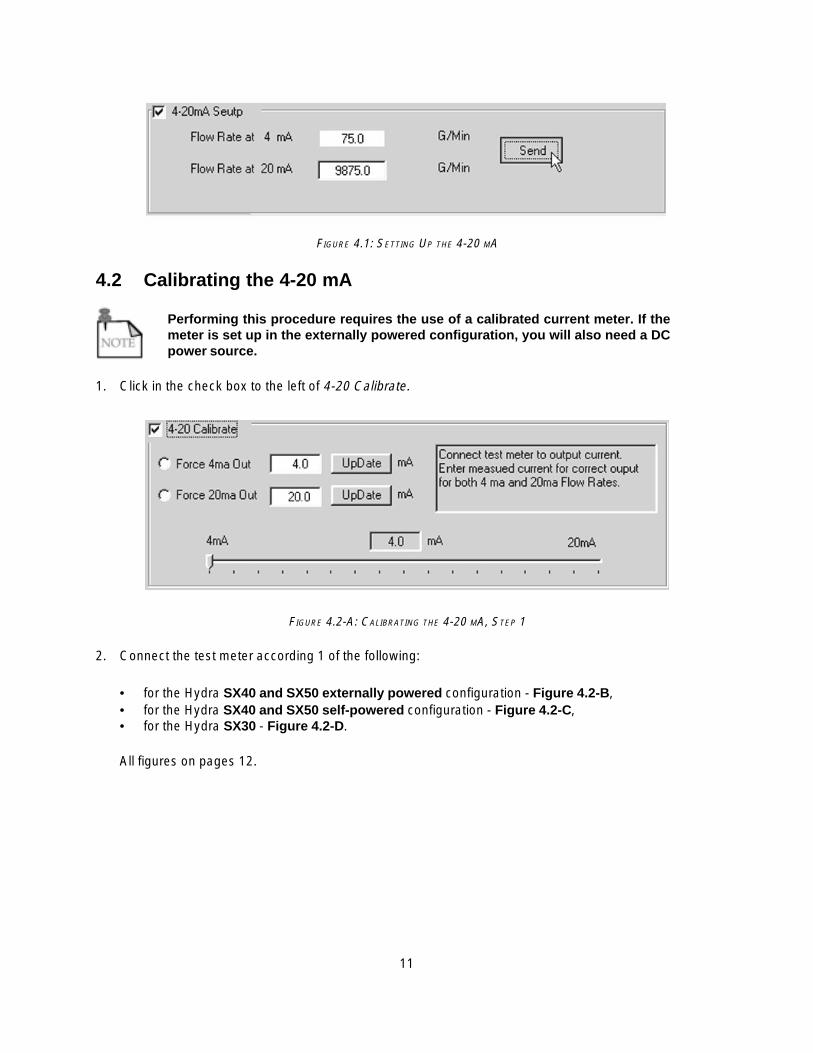
FIGURE 4.1: SETTING UP THE 4-20 MA
4.2 Calibrating the 4-20 mA
Performing this procedure requires the use of a calibrated current meter. If themeter is set up in the externally powered configuration, you will also need a DCpower source.
1. Click in the check box to the left of 4-20 Calibrate.
FIGURE 4.2-A: CALIBRATING THE 4-20 MA, STEP 1
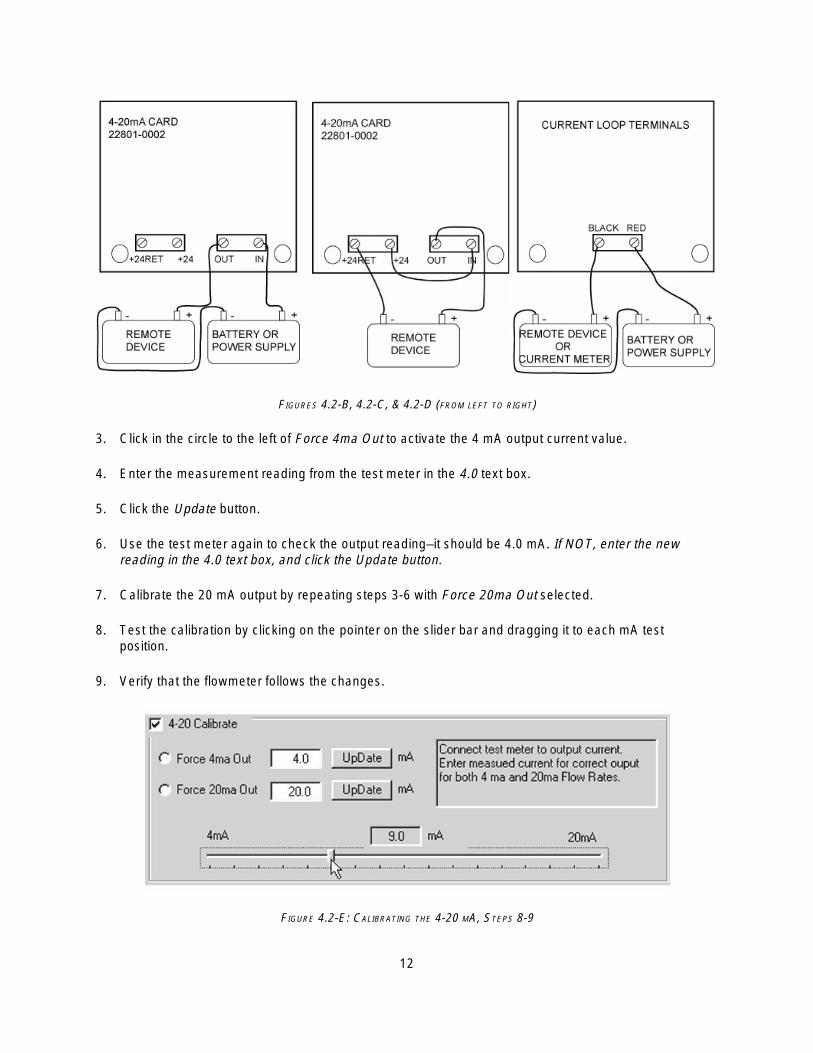
2. Connect the test meter according 1 of the following:
• for the Hydra SX40 and SX50 externally powered configuration - Figure 4.2-B,• for the Hydra SX40 and SX50 self-powered configuration - Figure 4.2-C,• for the Hydra SX30 - Figure 4.2-D.
All figures on pages 12.
12
FIGURES 4.2-B, 4.2-C, & 4.2-D (FROM LEFT TO RIGHT)
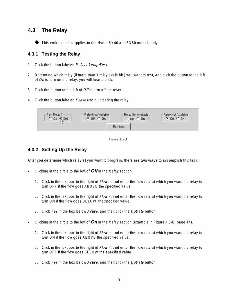
3. Click in the circle to the left of Force 4ma Out to activate the 4 mA output current value.
4. Enter the measurement reading from the test meter in the 4.0 text box.
5. Click the Update button.
6. Use the test meter again to check the output reading–it should be 4.0 mA. If NOT, enter the newreading in the 4.0 text box, and click the Update button.
7. Calibrate the 20 mA output by repeating steps 3-6 with Force 20ma Out selected.
8. Test the calibration by clicking on the pointer on the slider bar and dragging it to each mA testposition.
9. Verify that the flowmeter follows the changes.
FIGURE 4.2-E: CALIBRATING THE 4-20 MA, STEPS 8-9
13
4.3 The Relay
����� This entire section applies to the Hydra SX40 and SX50 models only.
4.3.1 Testing the Relay
1. Click the button labeled Relays Setup/Test.
2. Determine which relay (if more than 1 relay available) you want to test, and click the button to the leftof On to turn on the relay; you will hear a click.
3. Click the button to the left of Off to turn off the relay.
4. Click the button labeled Exit test to quit testing the relay.
FIGURE 4.3-A
4.3.2 Setting Up the Relay
After you determine which relay(s) you want to program, there are two ways to accomplish this task:
• Clicking in the circle to the left of Off in the Relay section.
1. Click in the text box to the right of Flow >, and enter the flow rate at which you want the relay toturn OFF if the flow goes ABOVE the specified value.
2. Click in the text box to the right of Flow <, and enter the flow rate at which you want the relay toturn ON if the flow goes BELOW the specified value.
3. Click Yes in the box below Active, and then click the UpDate button.
• Clicking in the circle to the left of On in the Relay section (example in Figure 4.3-B, page 14).
1. Click in the text box to the right of Flow >, and enter the flow rate at which you want the relay toturn ON if the flow goes ABOVE the specified value.
2. Click in the text box to the right of Flow <, and enter the flow rate at which you want the relay toturn OFF if the flow goes BELOW the specified value.
3. Click Yes in the box below Active, and then click the UpDate button.

14
FIGURE 4.3-B

15
5. THE LIMITS PAGE
Click on the tab labeled Limits to access the lost power feature, to set up the data logger, or to change thetime.
FIGURE 5
5.1 Setting the Time & Date
FIGURE 5.1
This section displays thetime and date as pro-grammed into the software.To adjust the time and/ordate, click in the text boxesunder Set Time/Date, andenter the new values. Thenclick Send.

16
5.2 The Datalogger
5.2.1 Setting Up the Datalogger
FIGURE 5.2-A
1. In the Log section, click in the circle to the left of On to enablethe logger.
2. Select the rate at which the function logs data by clicking inthe circle to the left of the desired interval. The log rateoptions are intervals of 0.5 minute (30 s), 1 minute, 5minutes, 15 minutes, and 60 minutes.
Click in the circle to the left of Off to disable the logger.
5.2.2 Using HydraLink with the Datalogger
1. Click Retrieve Unit Log from the Flow page.
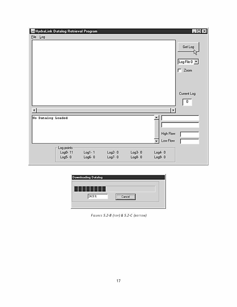
2. After the HydraLink window opens, click on the Get Log button, and the software begins downloadingdata from the logger.
Double click on Log Points (bottom of Figure 5.2-B, page 17) to update all the logpoints.
5.2.3 Opening Saved Log Files
If you do not have the HydraLink program open, first go to Flow page and click onthe Retrieve Unit Log button.
1. Click on File in the HydraLink window.
2. Select Load Log.
3. Use standard Windows procedures to retrieve the log file from your computer or floppy disk.
5.2.4 Saving Log Files
1. Click on File in the HydraLink window.
2. Select Save.
3. Use standard Windows procedures for saving log files to your computer or floppy disk.
17
FIGURES 5.2-B (TOP) & 5.2-C (BOTTOM)
18
5.2.5 Erasing Log Files
Performing the following procedure will erase ALL the log information stored inthe flowmeter. You CANNOT erase a specific log file.
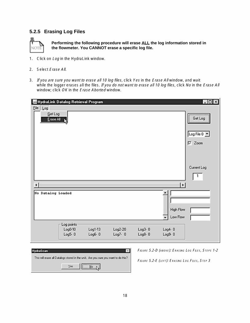
1. Click on Log in the HydraLink window.
2. Select Erase All.
3. If you are sure you want to erase all 10 log files, click Yes in the Erase All window, and waitwhile the logger erases all the files. If you do not want to erase all 10 log files, click No in the Erase Allwindow; click OK in the Erase Aborted window.
FIGURE 5.2-D (ABOVE): ERASING LOG FILES, STEPS 1-2
FIGURE 5.2-E (LEFT): ERASING LOG FILES, STEP 3
19
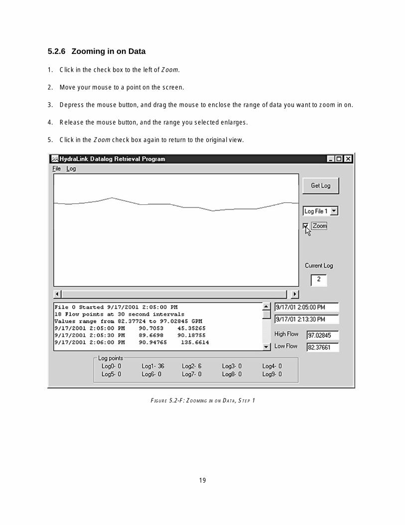
5.2.6 Zooming in on Data
1. Click in the check box to the left of Zoom.
2. Move your mouse to a point on the screen.
3. Depress the mouse button, and drag the mouse to enclose the range of data you want to zoom in on.
4. Release the mouse button, and the range you selected enlarges.
5. Click in the Zoom check box again to return to the original view.
FIGURE 5.2-F: ZOOMING IN ON DATA, STEP 1
20
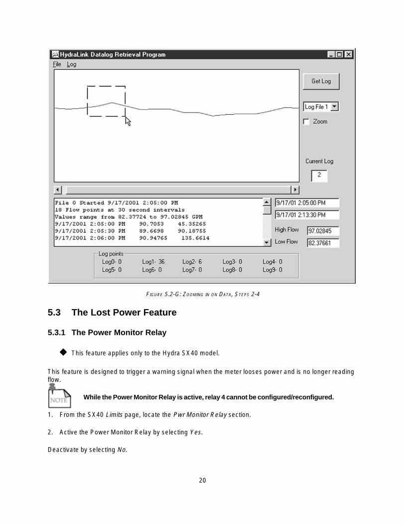
FIGURE 5.2-G: ZOOMING IN ON DATA, STEPS 2-4
5.3 The Lost Power Feature
5.3.1 The Power Monitor Relay
����� This feature applies only to the Hydra SX40 model.
This feature is designed to trigger a warning signal when the meter looses power and is no longer readingflow.
While the Power Monitor Relay is active, relay 4 cannot be configured/reconfigured.
1. From the SX40 Limits page, locate the Pwr Monitor Relay section.
2. Active the Power Monitor Relay by selecting Yes.
Deactivate by selecting No.
21
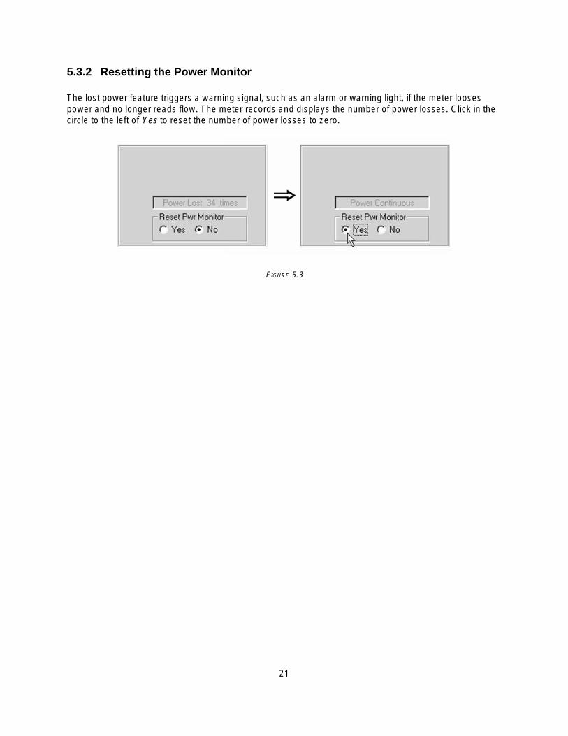
5.3.2 Resetting the Power Monitor
The lost power feature triggers a warning signal, such as an alarm or warning light, if the meter loosespower and no longer reads flow. The meter records and displays the number of power losses. Click in thecircle to the left of Yes to reset the number of power losses to zero.
FIGURE 5.3

22
6. THE MISC. PAGE
The Misc. page allows you to access to various overrides, adjust the LCD contrast, and perform a MasterErase.
FIGURE 6
6.1 Accessing the Overrides
6.1.1 Fast Learn
This option provides you with the ability to increase flowmeter response time by disabling some automaticfunctions. Complete the following steps to reduce learn time (while in normal operation) when the flowduration is not long enough to complete the learning process:
1. Click the circle to the left of Yes in the Fast Learn box.
2. Click the Learn Application button, and the meter goes into Learn mode.

23
6.1.2 Range Mode
Enabling this override allows a faster reaction time when needed on a start/stop application; it also allowssemi-manual operation.
1. Click in the circle to the left of Man in the Range Mode section.
2. Select the lowest range in which the maximum expected flow velocity does not exceed 50% of therange.
3. Click in the Signal Strength Cutoff text box, and enter a value above zero but below the signalstrength indicated during flow.
6.1.3 Tx Power
In applications where the signal strength is low, the meter automatically selects high transmit power. Youcan manually select regular or high power in applications where the signal strength is marginal or whereyou feel increased or decreased power output may improve signal quality.
6.1.4 4088XQ Mode
Utilize this option when fast reaction time is required. This override deactivates the Learn mode, and allsettings must be manually entered.
1. Click in the circle to the left of Yes in the 4088XQ mode section.
2. You must enter all settings manually (range, signal strength cutoff, etc.).
3. Click in the Signal Quality Cutoff text box, and enter a value approximately half the signal qualityindicated during flow.
6.1.5 Other Overrides
There are three additional overrides you can access on this page–Signal Strength Override (SSO), LowFlow Override (LFO), and Both.
• SSO: When the signal is less than 1% of full scale in normal operation, the output is automaticallyforced to zero and Learn mode is disabled. Activate this override to enable the meter to read flow inthis situation.
• LFO: The meter’s specified operating range is 0.2 ft/s to 32 ft/s, causing the meter to read zero flow atvelocities below 0.2 ft/s. Selecting this override allows you to manually enter any low flow cutoff (zerois NOT recommended).
• Both: Select this override to activate the SSO and LFO.

24
...6.1.5 Other Overrides continued
1. Click the arrow to the right of OverRides to access the drop-down menu.
2. Select the desired override.
6.2 Adjusting the Contrast
Click the up arrow to increase (darken) the display or the down arrow to decrease (lighten) thedisplay.Click Send.
6.3 Master Erase
Perform a Master Erase ONLY when you want all configuration information deleted and reset tofactory defaults.
6.3.1 Performing a Master Erase from the Misc. Page
����� This method applicable to the Hydra SX50 model only.
FIGURE 6.3
1. Click the button labeled Master Erase.
2. Click Yes to continue, and continue to step3; click No if you do not want to continue withthe master erase, and skip step 3.
3. Return to the SX50 Pipe page; you are readyto configure the meter.
6.3.2 Performing a Master Erase from Main HydraScan Window
1. Click Comm located on the opening HydraScan window, and select Master Erase.
2. Click Yes to continue, and continue to step 3; to abort the process, click No.
3. Follow the directions on the window that appears.
4. Go to the Pipe page; you are ready to configure the meter.

This page intentionally left blank.

25
7. THE DIAGNOSTICS PAGES
7.1 The Flow Page
The Flow page contains all pertinent flow information such as flow rate, velocity, signal strength, signalquality, etc.
FIGURE 7-A

26
7.2 The Time Domain Page
The information on this page is available for diagnostic purposes only.
FIGURE 7.2
27
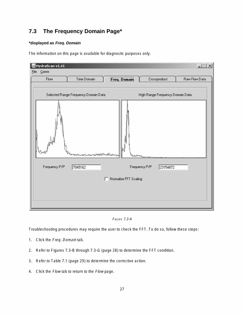
7.3 The Frequency Domain Page*
*displayed as Freq. Domain
The information on this page is available for diagnostic purposes only.
FIGURE 7.3-A
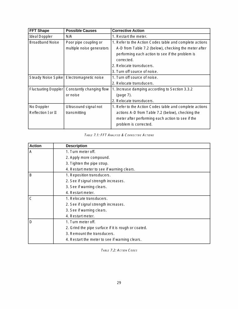
Troubleshooting procedures may require the user to check the FFT. To do so, follow these steps:
1. Click the Freq. Domain tab.
2. Refer to Figures 7.3-B through 7.3-G (page 28) to determine the FFT condition.
3. Refer to Table 7.1 (page 29) to determine the corrective action.
4. Click the Flow tab to return to the Flow page.

28
FIGURES 7.3-B (LEFT) & 7.3-C (RIGHT): IDEAL DOPPLER SHAPE & BROADBAND NOISE
FIGURES 7.3-D (LEFT) & 7.3-E (RIGHT): STEADY NOISE SPIKE WITH DOPPLER & FLUCTUATING DOPPLER PROFILE
FIGURES 7.3-F (LEFT) & 7.3-G (RIGHT): NO DOPPLER REFLECTION I & NO DOPPLER REFLECTION II
29
FFT Shape Possible Causes Corrective Action
Ideal Doppler N/A 1. Restart the meter.
Broadband Noise Poor pipe coupling or 1. Refer to the Action Codes table and complete actions
multiple noise generators A-D from Table 7.2 (below), checking the meter after
performing each action to see if the problem is
corrected.
2. Relocate transducers.
3. Turn off source of noise.
Steady Noise Spike Electromagnetic noise 1. Turn off source of noise.
2. Relocate transducers.
Fluctuating Doppler Constantly changing flow 1. Increase damping according to Section 3.3.2
or noise (page 7).
2. Relocate transducers.
No Doppler Ultrasound signal not 1. Refer to the Action Codes table and complete actions
Reflection I or II transmitting actions A-D from Table 7.2 (below), checking the
meter after performing each action to see if the
problem is corrected.
TABLE 7.1: FFT ANALYSIS & CORRECTIVE ACTIONS
Action Description
A 1. Turn meter off.
2. Apply more compound.
3. Tighten the pipe strap.
4. Restart meter to see if warning clears.
B 1. Reposition transducers.
2. See if signal strength increases.
3. See if warning clears.
4. Restart meter.
C 1. Relocate transducers.
2. See if signal strength increases.
3. See if warning clears.
4. Restart meter.
D 1. Turn meter off.
2. Grind the pipe surface if it is rough or coated.
3. Remount the transducers.
4. Restart the meter to see if warning clears.
TABLE 7.2: ACTION CODES
30
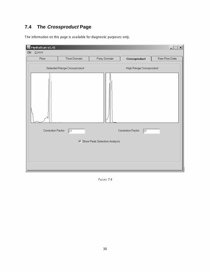
7.4 The Crossproduct Page
The information on this page is available for diagnostic purposes only.
FIGURE 7.4
31
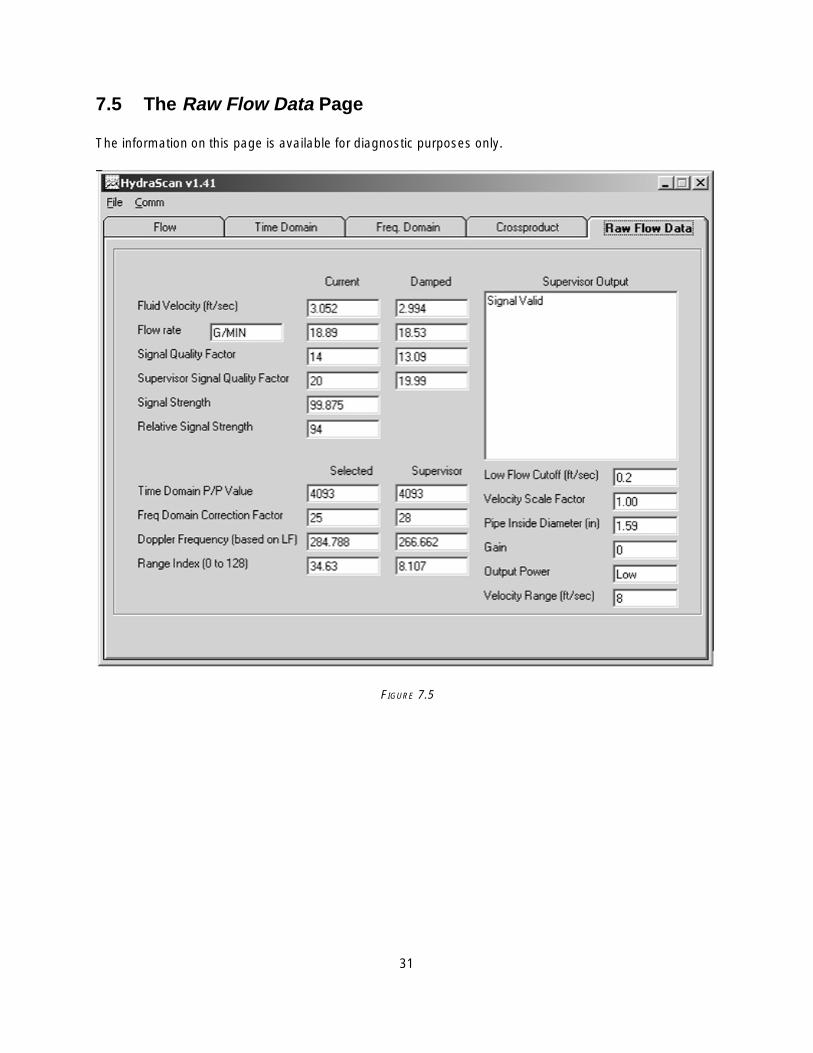
7.5 The Raw Flow Data Page
The information on this page is available for diagnostic purposes only.
FIGURE 7.5

This page intentionally left blank.

32
8. SERVICE & SUPPORT
8.1 Local Representative Support
The local representative is the first contact for support and is well-equipped to answer questions andprovide application assistance.
8.2 Service & Returns
If it becomes necessary to contact Thermo Fisher with software or hardware problems, please have thefollowing information available:
• flowmeter type • software version• signal strength • process temperature• transducer mounting configuration • power consumption• pipe orientation • fluid type• pipe OD and ID • pipe material• liner material • liner thickness• model number • serial number.
To return an instrument:
1. Contact Thermo Fisher for an RMA number (issued by the service representative). The receivingdock does not accept shipments without RMA numbers.
You can contact us at any of the following:
• Phone: (713) 272-0404 • Fax: (713) 272-5388• Web: www.thermofisher.com • Address: stated below
2. Ensure the instrument is well packed, in its original shipping box if available.
3. Include a letter fully explaining the symptoms of the failure as well as detail describing the applicationwhere the unit was being operated (type of fluid, pipe size, pipe material, etc.).
4. Write the RMA number on the outside of the shipping box.
5. Send the unit freight-paid to:
Thermo Fisher Scientific1410 Gillingham LaneSugar Land, TX 77478USA

33
8.3 Warranty Statement
Thermo Scientific products are warranted to be free from defects in material and workmanship at the time of shipment and for one year thereafter. Any claimed defects in Thermo Scientific products must be reported within the warranty period. Thermo Fisher shall have the right to inspect such products at Buyer’s plant or to require Buyer to return such products to Thermo Fisher plant.
In the event Thermo Fisher requests return of its products, Buyer shall ship with transportation charges paid bythe Buyer to Thermo Fisher plant. Shipment of repaired or replacement goods from Thermo Fisher plant shall beF.O.B. Thermo Fisher plant. A shop charge may apply for alignment and calibration services. Thermo Fisher shall be liable only to replace or repair, at its option, free of charge, products which are found by Thermo Fisher to be defective in material or workmanship, and which are reported to Thermo Fisher within the warranty period as provided above.This right to replacement shall be Buyer’s exclusive remedy against Thermo Fisher.
Thermo Fisher shall not be liable for labor charges or other losses or damages of any kind or description, including but not limited to, incidental, special or consequential damages caused by defective products. Thiswarranty shall be void if recommendations provided by Thermo Fisher or its Sales Representatives are notfollowed concerning methods of operation, usage and storage or exposure to corrosive conditions.
Materials and/or products furnished to Thermo Fisher by other suppliers shall carry no warranty except suchsuppliers’ warranties as to materials and workmanship. Thermo Fisher disclaims all warranties, expressed orimplied, with respect to such products.
EXCEPT AS OTHERWISE AGREED TO IN WRITING BY Thermo Fisher, THE WARRANTIES GIVEN ABOVEARE IN LIEU OF ALL OTHER WARRANTIES, EXPRESSED OR IMPLIED, AND Thermo Fisher HEREBYDISCLAIMS ALL OTHER WARRANTIES, INCLUDING THOSE OF MERCHANTABILITY AND FITNESSFOR PURPOSE.
34
APPENDIX A: PIPE ID CHARTS
X S
TG
0.95
7 1.
278
1.50
0 1.
939
2.32
3
2.90
0 3.
364
3.82
6 4.
813
5.76
1
7.62
5 9.
750
11.7
50
13.0
00
15.0
00
17.0
00
19.0
00
23.0
00
29.0
00
35.0
00
41.0
00
47.0
00
Std
. W
all
1.04
9 1.
380
1.61
0 2.
067
2.46
9
3.06
8 3.
548
4.02
6 5.
047
6.06
5
7.98
1 10
.020
12
.000
13
.250
15
.250
17.2
50
19.2
50
23.2
50
29.2
50
35.2
50
41.2
50
47.2
50
Sch
ed.
160
0.81
5 1.
160
1.33
8 1.
687
2.12
5
2.62
4 3.
438
4.31
3 5.
187
6.81
3 8.
500
10.1
26
11.1
88
12.8
12
14.4
38
16.0
62
19.3
12
31.3
12
Sch
ed.
140
7.00
1 8.
750
10.5
00
11.5
00
13.1
24
14.8
76
16.5
00
19.8
76
31.8
76
Sch
ed.
120
3.62
4 4.
563
5.50
1
7.18
7 9.
062
10.7
50
11.8
76
13.5
62
15.2
55
17.0
00
20.3
76
Sch
ed.
100
7.43
7 9.
312
11.0
62
12.1
24
13.9
38
15.6
88
17.4
38
20.9
38
Sch
ed.
80
0.95
7 1.
278
1.50
0 1.
939
2.32
3 2.
900
3.36
4 3.
826
4.81
3 5.
761
7.62
5 9.
562
11.3
74
12.5
00
14.3
12
16.1
24
17.9
38
21.5
62
Sch
ed.
60
7.81
3 9.
750
11.6
26
12.8
12
14.6
88
16.5
00
18.3
76
22.0
62
Sch
ed.
40
1.04
9 1.
380
1.61
0 2.
067
2.46
9
3.06
8 3.
548
4.02
6 5.
047
6.06
5
7.98
1 10
.020
11
.938
13
.124
15
.000
16.8
76
18.8
12
22.6
24
28.5
00
34.5
00
40.5
00
47.2
50
Sch
ed.
30
8.07
1 10
.136
12
.090
13
.250
15
.250
17.1
24
19.0
00
22.8
76
28.7
50
34.7
50
40.7
50
Sch
ed.
20
8.12
5 10
.250
12
.250
13
.376
15
.376
17.3
76
19.2
50
23.2
50
29.0
00
35.0
00
41.0
00
Sch
ed. 1
0 (L
igh
t W
all)
1.09
7 1.
442
1.68
2 2.
157
2.63
5
3.26
0 3.
760
4.26
0 5.
295
6.35
7
8.32
9 10
.420
12
.390
13
.500
15
.500
17.5
00
19.5
00
23.5
00
29.3
76
35.3
76
Sch
ed.
5
1.18
5 1.
530
1.77
0 2.
245
2.70
9
3.33
4 3.
834
4.33
4 5.
345
6.40
7
8.40
7 10
.482
12
.438
15
.670
17.6
70
19.6
34
23.5
64
29.5
00
OD
1.31
5 1.
660
1.90
0 2.
375
2.87
5 3.
500
4.00
0 4.
500
5.56
3 6.
625
8.62
5 10
.750
12
.750
14
.000
16
.000
18.0
00
20.0
00
24.0
00
30.0
00
36.0
00
42.0
00
48.0
00
Tab
le A
-1
Ste
el, S
tain
less
Ste
el a
nd
PV
C P
ipe
Sta
nd
ard
Sch
edu
les
In
sid
e D
iam
eter
(ID
) an
d O
uts
ide
Dia
met
er (
OD
) in
Inch
es
No
min
al
Pip
e S
ize
1 1.25
1.
5 2 2.
5
3 3.5
4 5 6 8 10
12
14
16
18
20
24
30
36
42
48

35
ID
6.00
8.
00
10.0
0
12.0
0 14
.00
16.0
0 18
.00
20.0
0
24.0
0
Cla
ss H
OD
7.38
9.
60
11.8
4
14.0
8 16
.32
18.5
4 20
.78
23.0
2
27.7
6
ID
6.08
8.
10
10.1
2
12.1
4 14
.18
16.1
8 18
.22
20.2
4 24
.26
Cla
ss G
OD
7.38
9.
60
11.8
4
14.0
8 16
.32
18.5
4 20
.78
23.0
2
27.7
6
ID
6.00
8.
10
10.0
0
12.0
0 14
.00
16.0
0 18
.00
20.0
0
24.0
0 30
.00
36.0
0
Cla
ss F
OD
7.22
9.
42
11.6
0
13.7
8 15
.98
18.1
6 20
.34
22.5
4
26.9
0 33
.46
40.0
4
ID
6.06
8.
10
10.1
2
12.1
4 14
.18
16.2
0 18
.20
20.2
4
24.2
8 30
.00
36.0
0
Cla
ss E
OD
7.22
9.
42
11.6
0
13.7
8 15
.98
18.1
6 20
.34
22.5
4
26.9
0 33
.10
39.6
0
ID
3.00
3.
96
6.00
8.
10
10.0
4
12.0
0 14
.01
16.0
2 18
.00
20.0
0
24.0
0 30
.00
36.0
0 42
.02
48.0
0
53.9
4 60
.06
Cla
ss D
OD
3.96
5.
00
7.10
9.
30
11.4
0
13.5
0 15
.65
17.8
0 19
.92
22.0
6
26.3
2 32
.74
39.1
6 45
.58
51.9
8
58.4
0 64
.82
ID
3.06
4.
04
6.08
8.
18
10.1
6
12.1
4 14
.17
16.2
0 18
.18
20.2
2
24.2
2 30
.00
35.9
8 42
.02
47.9
8
54.0
0 60
.20
72.1
0
Cla
ss C
OD
3.96
5.
00
7.10
9.
30
11.4
0
13.5
0 15
.65
17.8
0 19
.92
22.0
6
26.3
2 32
.40
38.7
0 45
.10
51.4
0
57.8
0 64
.20
76.8
8
ID
3.12
4.
10
6.14
8.
03
9.96
11.9
6 13
.98
16.0
0 18
.00
20.0
0
24.0
2 29
.94
36.0
0 41
.94
47.9
6
54.0
0 60
.06
72.1
0 84
.10
Cla
ss B
OD
3.96
5.
00
7.10
9.
05
11.1
0
13.2
0 15
.30
17.4
0 19
.50
21.6
0
25.8
0 32
.00
38.3
0 44
.50
50.8
0
57.1
0 63
.40
76.0
0 88
.54
ID
3.02
3.
96
6.02
8.
13
10.1
0
12.1
2 14
.16
16.2
0 18
.22
20.2
6
24.2
8 28
.98
35.9
8 42
.00
47.9
8
53.9
6 60
.02
72.1
0 84
.10
Cla
ss A
OD
3.80
4.
80
6.90
9.
05
11.1
0
13.2
0 15
.30
17.4
0 19
.50
21.6
0
25.8
0 31
.74
37.9
6 44
.20
50.5
0
56.6
6 62
.80
75.3
4 87
.54
Tab
le A
-2
Cas
t Ir
on
Pip
e S
tan
dar
d C
lass
es
Insi
de
Dia
met
er (
ID)
an
d O
uts
ide
Dia
met
er (
OD
) in
Inch
es
No
min
al
Pip
e S
ize
3 4 6 8 10
12
14
16
18
20
24
30
36
42
48
54
60
72
84
NO
TE
: F
or p
ipes
with
cem
ent l
inin
gs, r
educ
e th
e pi
pe in
side
dia
met
er b
y tw
o tim
es th
e lin
ing
thic
knes
s. S
tand
ard
and
doub
le c
emen
t lin
ing
thic
knes
ses
are
liste
d in
Tab
le B
-3.
36
Do
ub
le
Th
ickn
ess
0.25
0
0.37
5
0.50
0
Cem
ent
Lin
ing
(S
ee N
ote
)
Sta
nd
ard
T
hic
knes
s
0.12
5
0.18
75
0.25
0
Cla
ss 5
6
3.16
3.
98
6.04
8.
15
10.1
6 12
.22
14.2
8 16
.36
18.4
4 20
.52
24.6
8
30.7
4 36
.84
42.8
4 48
.94
55.0
0
Cla
ss 5
5
3.22
4.
04
6.10
8.
21
10.2
2 12
.28
14.3
4 16
.42
18.5
0 20
.58
24.7
4
30.8
2 36
.94
42.9
6 49
.08
55.1
6
Cla
ss 5
4
3.28
4.
10
6.16
8.
27
10.2
8 12
.34
14.4
0 16
.48
18.5
6 20
.64
24.8
0
30.9
0 37
.04
43.0
8 49
.22
55.3
2
Cla
ss 5
3
3.34
4.
16
6.22
8.
33
10.3
4 12
.40
14.4
6 16
.54
18.6
2 20
.70
24.8
6
30.9
8 37
.14
43.2
0 49
.36
55.4
8
Cla
ss 5
2
3.40
4.
22
6.28
8.
39
10.4
0 12
.46
14.5
2 16
.60
18.6
8 20
.76
24.9
2
31.0
6 37
.06
43.3
2 49
.50
55.6
4
Cla
ss 5
1
3.46
4.
28
6.34
8.
45
10.4
6 12
.52
14.5
8 16
.66
18.7
4 20
.82
24.9
8
31.1
4 37
.34
43.4
4 49
.64
55.8
0
Insi
de
Dia
met
er
Cla
ss 5
0
6.40
8.
51
10.5
2 12
.58
14.6
4 16
.72
18.8
0 20
.88
25.0
4
31.2
2 37
.44
43.5
6 49
.78
55.9
6
OD
3.96
4.
80
6.90
9.
05
11.1
0 13
.20
15.3
0 17
.40
19.5
0 21
.60
25.8
0
32.0
0 38
.30
44.5
0 50
.80
57.1
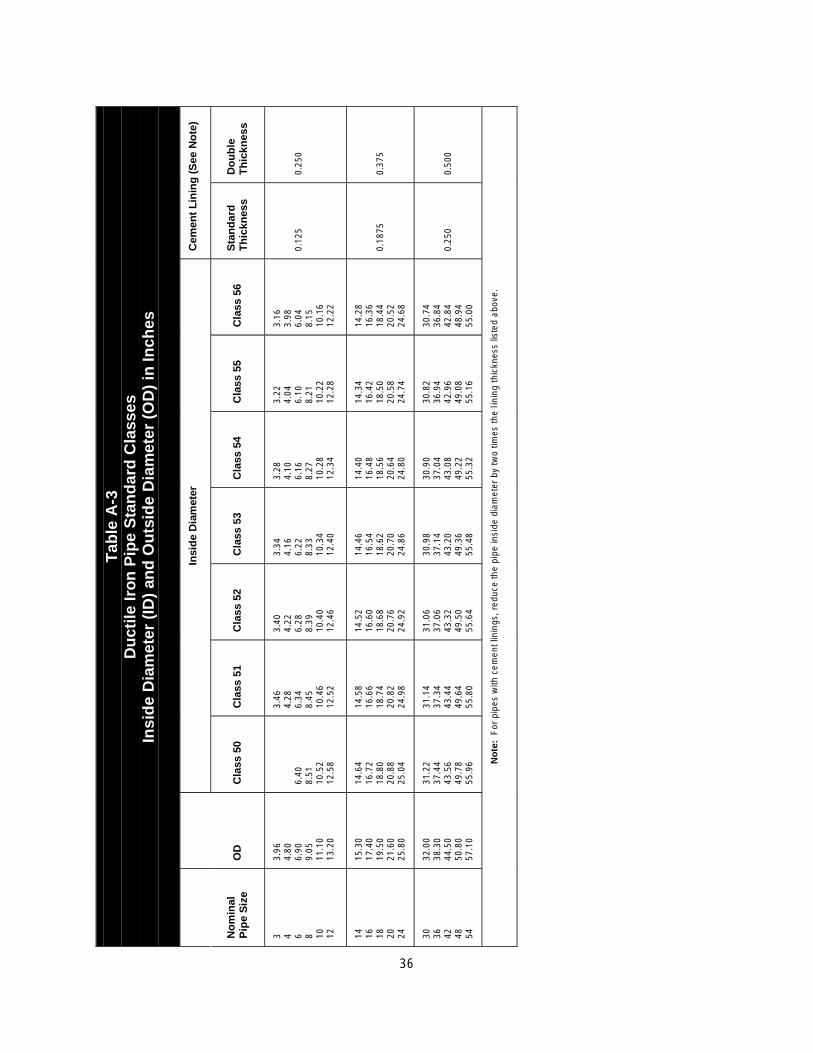
0
Tab
le A
-3
Du
ctile
Iro
n P
ipe
Sta
nd
ard
Cla
sses
In
sid
e D
iam
eter
(ID
) an
d O
uts
ide
Dia
met
er (
OD
) in
Inch
es
No
min
al
Pip
e S
ize
3 4 6 8 10
12
14
16
18
20
24
30
36
42
48
54
No
te:
For
pip
es w
ith c
emen
t lin
ings
, red
uce
the
pipe
insi
de d
iam
eter
by
two
times
the
linin
g th
ickn
ess
liste
d ab
ove.

This page intentionally left blank.

Thermo Fisher Scientific81 Wyman StreetP.O. Box 9046Waltham, Massachusetts 02454-9046United States
www.thermofisher.com