hybrid membrane systems in waste management - …infohouse.p2ric.org/ref/27/26818.pdf · hybrid...
TRANSCRIPT

Hybrid Membrane Systems in Waste Management
Presented by William F. Weber
Du Pont Separation System E. I. Du Pont De Nemours & Co. (Inc.)
Wilmington, Delaware
. (Originally Presented at the Membrane Technology Planning Conference Cambridge, Massachusetts - November 6, 1986)

L
ai
INTRODUCTION
Whenever one is pursuing a new market, there are several
basic questions which need to be answered.
The crossflow membrane filtration market is no different.
MARKET POTENTIAL
The first question one hears is: "How big is the market?"
Last year, we outlined Du Pont's perspective to this ques-
tion. As you'll recall, the forecast for sales of membrane
systems and services in gas and liquid processing applications
was expected to increase from $500MM in 1985 to over $2MMM by
1995.
Our experience since that time has confirmed that there are
significant and emerging opportunities for membranes in food
processing, aqueous waste management, gas separations and
biotechnical applications. Specifically in the market of treat-
ment of hazardous wastes, the potential for the use of membrane
systems is outstanding. As can be seen in Figure 1, approximate-
ly 270 million tons of hazardous wastes regulated under the
Resource Conservation and Recovery Act (RCRA) are generated in
the United States annually. Over 60 percent of this total is in
the form of dilute aqueous wastes, most of which contains 0.1-1.0
percent of hazardous constituents. Industry spends about 11 to
12 billion dollars a year to treat these wastes. Historically,
most of this treatment has consisted of on-site conventional
primary and/or secondary treatment prior to discharge to a local
surface water or municipal sewer. However, the regulations on -
223
,
these discharges is being tightened every year, mandating the
need for additional treatment. The technologies being looked
upon as most likely to fill this treatment gap are carbon absorp-
tion, ion exchange, steam/air stripping and membrane separation.
If membranes can be adopted to even a small portion of this
opportunity, it will represent a very attractive market niche to
go after. We estimate membrane systems and services sold into
this emerging market niche within the last year was over $25
million dollars.
CRITICAL SUCCESS FACTORS
Once one has sufficiently proven that the opportunity is
a large enough carrot to go after, the next question is "What do
we have to do to get it?". B
First, one has to be sure to target the right applications, 1 t .
4 especially because in most waste treatment cases membranes are
only one of several alternate separation technologies available.
Therefore, to determine whether or not membranes are right for a
given application, one must consider the specific site conditions
such as: -
0 System Size - flow rates up to 100,000 gallons per day (gpd) are often attractive.
0 Nature of Constituents to be Removed - the higher the mol2cular weight, the better.
0 Purity Requirements - removal of over 95 percent often needs polishing steps in addition to membrane separa-
tions. -
2 2 4

But even if a potential application fits these criteria,
there' are several other even more important critical success
factors required from the supplier of the membrane system, as
follows:
0 Understanding of the membrane capabilities and limita-
tions.
0 Access to various kinds of membranes - including microfiltration, ultrafiltration and reverse osmosis - '
as well as various configurations - such as spiral, hollow fiber, tubular and plate and frame.
o Ability to provide non-membrane options for
pretreatment, polishing and/or ultimate disposal.
o Ability to engineer the integration of membrane unit
processes with other unit processes into a hybrid
system.
o
o
Ability to deliver a low cost system.
Ability to provide full service for these systems,
including start-up, operation and troubleshooting. -
It is worth repeating that the capability to integrate
membranes into an overall hybrid separation system is critical to
be successful in emerging separation applications.
225

CASE HISTORIES
inal ally, Once one has reasoned that a target market is big
enough at which to shoot, and one has determined a direction in
which to shoot, only one question remains - "Can you prove it?". The remainder of this paper will give a brief review of some
of the applications in which we have recently been.involved which
begin to "prove out" that membrane systems do work!
1.) TEXTILE FINISH WASTE
The first case deals with the use of a membrane system
to concentrate industrial wastes for more economical dispos-
al. It involves textile finish wastes from the manufacture
of synthetic textile fibers,
Textile finish wastes are similar in some respects to
metal finishing oils, but they can be more difficult to
treat because each textile product may use a different
finish formulation and each plant uses a variety of finishes
simultaneously. A typical formulation may contain 8 to 10
components, many of which are proprietary. In general
though, the finish is a mixture of surfactants, oils and
polymers.
At this site, the waste disposal problem was two-fold.
First, the permit for the existing disposal technique of
spray irrigation onto a field was about to expire and the
manufacturer did not expect it to be renewed. Secondly, the
manufacturer was introducing several new finish formulations -
226
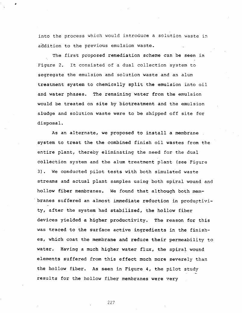
into the process which would introduce a solution waste in
aadition to the previous emulsion waste.
The first proposed remediation scheme can be seen in
Figure 2. It consisted of a dual collection system to
segregate the emulsion and solution waste and an alum
treatment system to chemically split the emulsion into oil
and water phases. The remaining water from the emulsion
would be treated on site by biotreatment and the emulsion
sludge and solution waste were to be shipped off site for
disposal.
As an alternate, we proposed to install a membrane
system to treat the the combined finish oil wastes from the
entire plant, thereby eliminating the need for the dual
collection system and the alum treatment plant (see Figure
3 ) . We conducted pilot tests with both simulated waste
streams and actual plant samples using both spiral wound and
hollow fiber membranes. We found that although both mem-
branes suffered an almost immediate reduction in productivi-
ty, after the system had stabilized, the hollow fiber -
devices yielded a higher productivity. The reason for this
was traced to the surface active ingredients in the finish-
es, which coat the membrane and reduce their permeability to
water. Having a much higher water flux, the spiral wound
elements suffered from this effect much more severely than
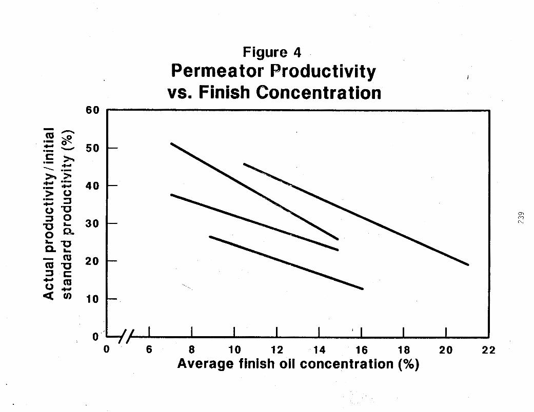
the hollow fiber. As seen in Figure 4 , the pilot study
results for the hollow fiber membranes were very -
227

c .
encouraging. High volume r e d u c t i o n of b o t h emulsion and
s o l u b l e wastes w a s achieved wi th ex t remely l o w p e n e t r a t i o n
of. f i n i s h through t h e membrane.
Based on t h e p i l o t t es t r e s u l t s , t h i s a l t e r n a t e
remedia t ion scheme was chosen f o r t h e f u l l s c a l e system
which i s shown i n F igu re 5. I t i s a 5 g a l l o n p e r minute
(gpm) system which o p e r a t e s i n a ba t ch mode f o r about 3 t o 6
hours p e r day. The waste from t h e v a r i o u s s p i n n i n g machines
are p u t i n t o a col lect ion tank t o allow t h e de-emuls i f ied
o i l s t o rise t o t h e s u r f a c e . Th i s material i s decanted i n t o
drums f o r i n c i n e r a t i o n . The remaining l i q u i d i s pumped
through a 1 micron f i l t e r and then a b i o c i d e i s added. From
t h e RO f eed tank , t h e m a t e r i a l i s f i l t e r e d a g a i n , pu t
through a h e a t exchanger t o main ta in 86OF, and pumped a t 4 0 0
p s i g t o p a r a l l e l hollow f i b e r permeators , The permeate goes
d i r e c t l y t o t h e b i o t r e a t m e n t f a c i l i t i e s and t h e c o n c e n t r a t e
i s r e c y c l e d back t o t h e f eed tank. I n t h i s way, t h e o i l s
are c o n c e n t r a t e d t o as much as 35% by weight .
A f t e r each ba tch t r ea tmen t , a regular c l e a n i n g o f t h e
membranes i s done w i t h a d e t e r g e n t s o l u t i o n a t a reduced
p res su re . This p reven t s any r e s i d u a l o i l s from
de-emulsifying w i t h i n t h e permeators. Once completed, t h e
s p e n t c l e a n i n g s o l u t i o n i s added t o t h e RO feed t ank ,
W e found t h a t membranes performance cou ld be improved
by t h e a d d i t i o n of c e r t a i n d e t e r g e n t a g e n t s t o t h e feed tank
which had t h e e f f e c t of improving c i r c u l a t i o n i n t h e
228

permeators. We use what we call a "working solution"
method, in which we estimate the quantity of detergent
necessary to concentrate a given volume of waste'and added
it'to the feed tank as it is filled the first time. '
This system has proven to be extremely cost-effective
(see Figure 6). By eliminating the alum splitting system
and dual waste collection for each machine, capital costs
were reduced from $900,000 to $150,00,0 for the membrane
system. More importantly, due to the volume reduction of
waste for off site disposal, disposal costs have been
reduced by over $250,000 per year. Due to the success of
this system, several other textile manufacturing plants have
modelled waste concentration systems after this one.
2 . ) PETROLEUM PRODUCTION BYPRODUCTS
Another example of waste concentration involves the
byproduct stream from offshore oil production. It illus-
trates the flexibility and varied experience that a membrane
supplier who is also a large industrial company can bring to
developmental technologies as well as commercial ones.
The byproduct stream consists primarily of seawater
with residual amounts of organics, primarily acetate-type
compounds with molecular weights ranging from 80 to 110.
The organic level was about 80 percent higher than the EPA
limit however, which prevented the disposal of this
byproduct stream directly back into the sea. -
229
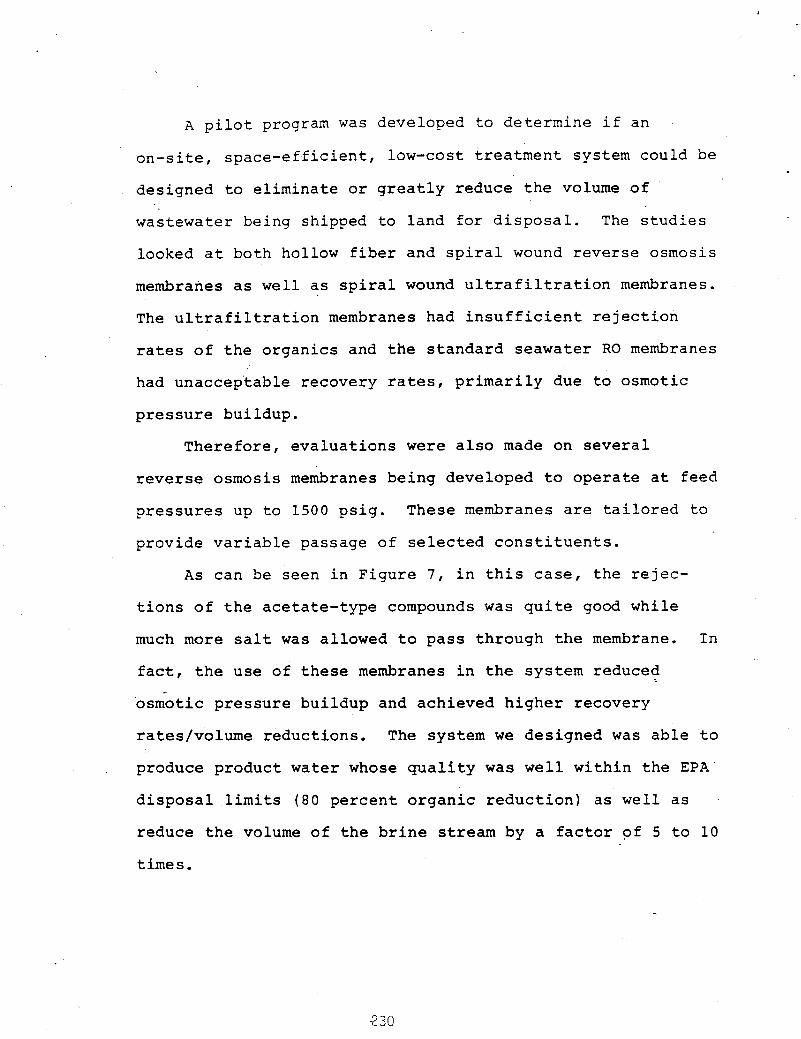
A pilot program was developed to determine if an
on-site, space-efficient, low-cost treatment system could be
designed to eliminate or greatly reduce the volume of '
wastewater being shipped to land for disposal. The studies
looked at both hollow fiber and spiral wound reverse osmosis
membranes as well as spiral wound ultrafiltration membranes.
The ultrafiltration membranes had insufficient rejection
rates of the organics and the standard seawater RO membranes
had unacceptable recovery rates, primarily due to osmotic
pressure buildup.
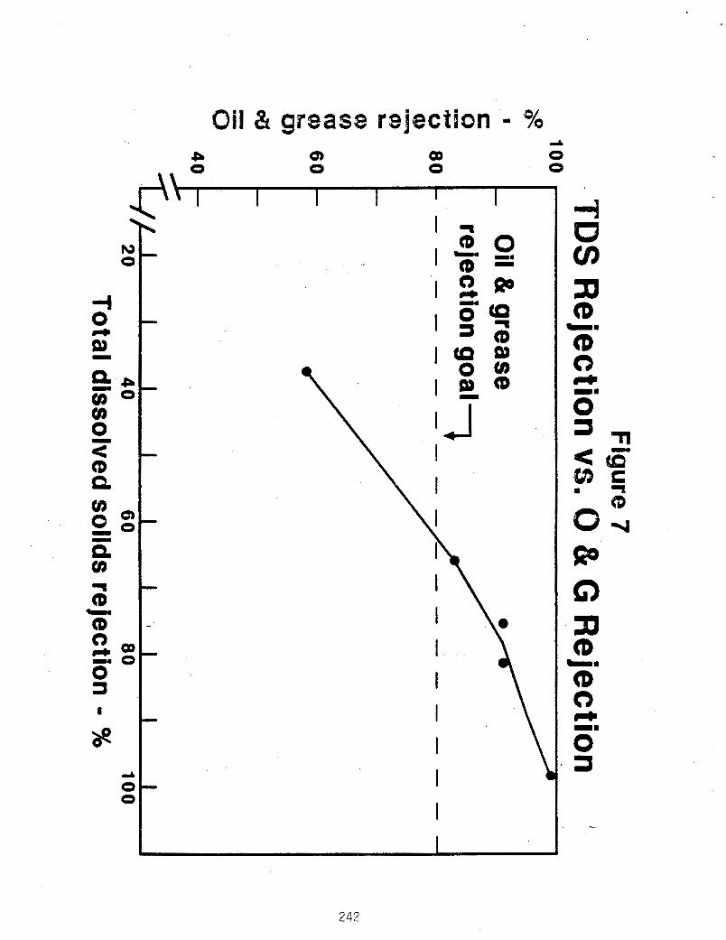
Therefore, evaluations were also made on several
reverse osmosis membranes being developed to operate at feed
pressures up to 1500 psig. These membranes are tailored to
provide variable passage of selected constituents.
A s can be seen in Figure 7 , in this case, the rejec-
tions of the acetate-type compounds was quite good while
much more salt was allowed to pass through the membrane. In
fact, the use of these membranes in the system reduced
osmotic pressure buildup and achieved higher recovery
rates/volume reductions. The system we designed was able to
produce product water whose quality was well within the EPA
disposal limits (80 percent organic reduction) as well as
reduce the volume of the brine stream by a factor of 5 to 10
times.
-2 30
3 . ) GROUNDWATER REMEDIATION
In this case, membranes economically assisted more
conventional remediation technologies to restore groundwater
which had been contaminated with industrial processing
waste. At the site in question, the originally proposed
remediation scheme called for a groundwater withdrawal of
130,000 gallons per day via a drain tile collection system
for subsequent treatment. It was determined that this
groundwater flowing into the collection system was picking
up in excess of 200 pounds of wastes (primarily volatile
organics) per day. The treatment objective was to remove
over 98 percent of the total groundwater volatile organic
compounds (VOC) and reduce each VOC constituent to no
greater than 5 0 parts per billion (Figure 8).
Four alternative treatment systems were considered:
0 biodegradation in a retention pond, which was consid-
ered too expensive;
0 air stripping, which was politically unacceptable in
the area since it would essentially transfer a large -
quantity of hazardous waste from the water into the
air;
0 steam stripping, which was technically feasible and
more cost effective than a biopond;
0 membrane system, which was considered to be potentially
the most economical solution if technical viability
could be demonstrated.
231

I
Accordingly, in-house feasibility tests were performed
'.with laboratory spiked samples of the volatile organic
compounds. Rejection and flux results of several different
commercially available reverse osmosis membranes showed the
"Permasep" B-10 permeator to be the most effective membrane.
Subsequently, a 5 gpm portable pilot system was tested on
site at a wide variety of operating conditions, including
feed pressures from 240 to 1000 psig and recovery rates from
38 to 92 percent.
Figures 9 and 10.
Results of these tests are summarized in
These tests demonstrated membrane concentration was
effective in reducing the VOC content by 85 to 90 percent,
and improvements were identified which raised that to 90 to
95 percent. A polishing step using air stripping would have
achieved the 98 percent VOC removal goal and still kept the
total discharge of VOC's to the air at less than the goal of
10 pounds per day.
Based on the pilot test results, the conceptual design
for a full scale system was prepared and is seen in Figure
11. When compared to the projected performance and cost of
a steam stripper, the hybrid system of a membrane system/air
stripper was shown to be effective alternative as can be
seen in Figures 12 and 13.
232

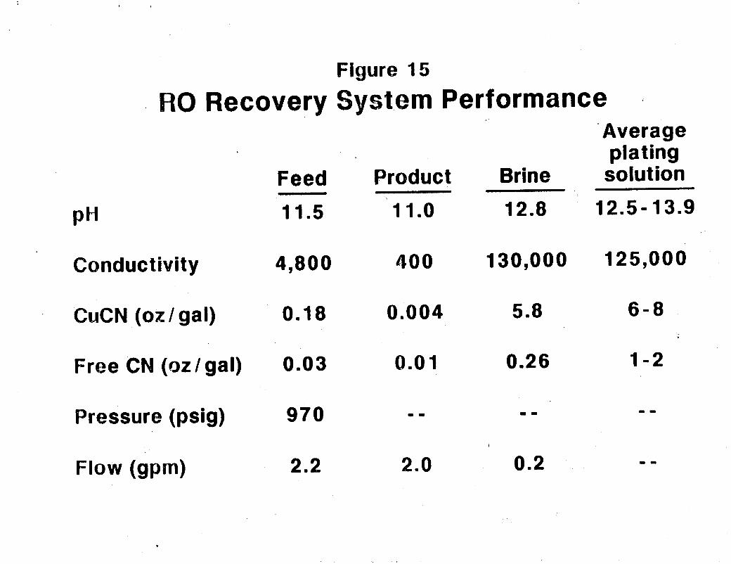
4 . ) RESOURCE RECOVERY
Here, an in-line closed loop system is used to prevent
valuable raw materials from becoming unusable and thus
disposed as wastes.
In one case, for example, we developed a system using
membranes to recovery copper cyanide from the rinse water in
a plating operation. Details of this system are in Figure
1 4 . The system separated the plating water into two
streams: a product stream having low TDS for direct dispos-
al to the public sewer or reuse in the rinse tanks, and a
highly concentrated brine containing the plating chemicals
for reuse in the plating bath. The membrane system operates
at approximately 1000 psig feed pressure and is sized to
treat 2.2 gpm feed flow (see Figure 15). The system oper-
ates at 90 to 95 percent recovery and rejects 97-98 percent
of the copper cyanide.
This system cut the company's processing costs two
ways. First, it allowed them to eliminate a waste treatment
sfstem along with the associated chemicals, manpower and
water. Second, it reduced their total purchases of raw
processing materials. The combined savings result in a
payback of the system cost within a matter of months.
In some cases, the payback period fo r a resource
recovery membrane system can be even shorter! We are
presently doing feasibility testing in a case involving the - recovery of an exotic dispersing agent used in a
233
polymerization process.
trate the effluent of an exhaust stream which has been
processed through a scrubber,
The system would be used to concen-
The full scale system would
be about 20 gpm.
in this process is over 5 million dollars annually, the cost
of a membrane system could be made up within a matter of
Since the value of dispersing agent used
days !
* CONCLUSIONS
Du Pont is committed to pursuing the waste management market
with hybrid membrane systems!
Why, can be seen from t b answers to these three questions:
0 How big is it - So big, that it's scary.
0 How do we get it! - By providing the total solution to the separation need.
0 Can you prove it - As shown in these examples, the
proof is in the pudding.
These answers also explain why we've gotten continued
interest from potential clients for new applications. We've been
able to demonstrate the significant economic, environmental, and
product quality advantages over other separation technologies.
But our demonstrations have only been successful in these unique
applications because we've committed ourselves to providing the
total solution to a client's separations need. We have tapped
into the extensive resources and experience of the Du Pont
company to provide hybrid membrane systems which are integrated - in the given site specific conditions of an application. For a
-
2 34
membrane system to be successful any or all of the following must
be offered: problem analysis, feasibility testing, solutions
design, systems fabrication and installation, and field service.
Only by assuming the f u l l responsibility f o r the separations
solution do we foresee the continued acceptance of membrane
separation as the next viable unit process for these emerging
icat ions
235

Aqueous Waste (61%)
Figure 1
Annu,aI Estimated Hazardous Waste Generation Total = 270 Million Tons
Organic Waste 16%
Sludges & Solids (4%)
Liquids (1 2%)
Inorganic Waste 23%
Sludges (8%)
Solids (15%)
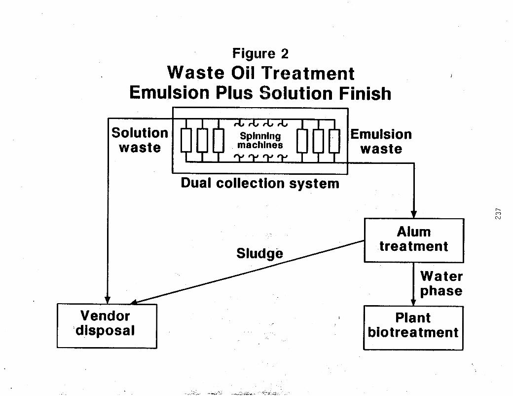
Figure 2 Waste Oil Treatment
Emulsion Plus slution Finish
Solution waste
Spinning machines
Dual collection system
Emulsion waste
I h m N
I Alum
Vendor 'dis p o s a I
Plant biot rea tmen t

Figure 3 Waste Oil Treatment
Combined Waste Usin embrane 1
Separation ___
Spinning machines
Combined waste r Single collection system
C P c - - 1 - -
Alum treatment
r 4
L /
/ 4
I Membrane separation
I Concentrate
x
4
J - - T - - I
Plant biotreatment
Vendor ’ disposal
68
5 0
40
38
20
10
0 ' 0
Figure 4 Permea tor Productivity vs. Finish Concentration
--, . ,
f / I I I I I I I I 6 8 10 12 14 16 18 20
Average finish oil concentration (%) 22
cn c7 N
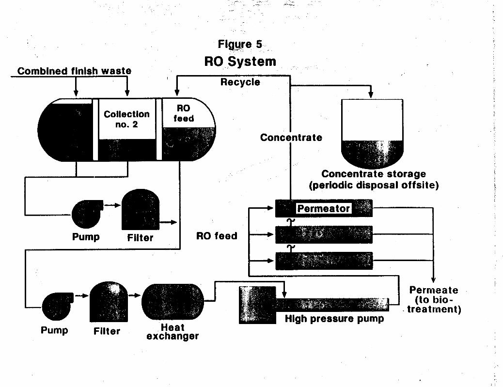
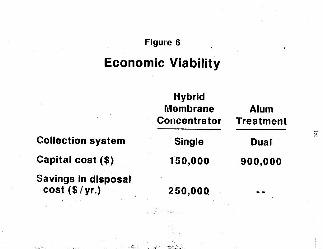
Figure 6
Economic Viability
Hybrid Membrane Alum
Concentrator Treatment
Collection system Single Dual l-i
d N
Capital cost ($) 150,000 900,000
Savings in disposal cost ($ / yr.) 250,000
I
" _
Oil & grease rejection - %
242
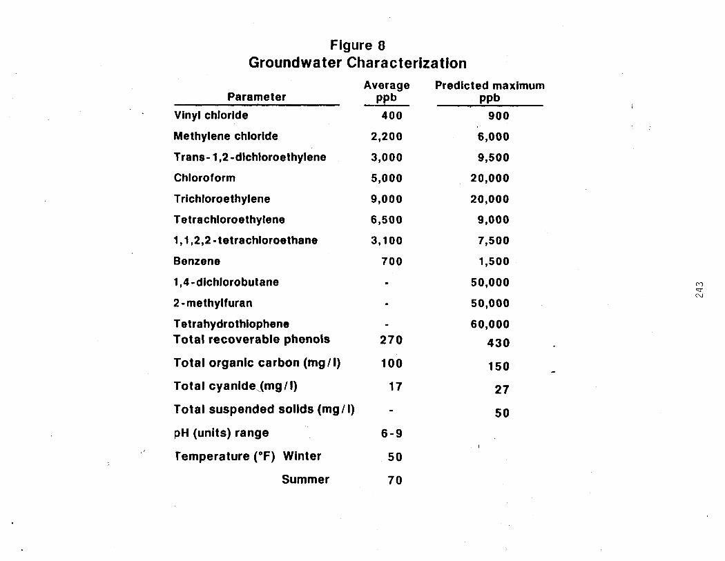
Figure 8 Groundwater Characterization
Average Predicted maximum Parameter PPb PPb
Vinyl chloride 400 900
Methylene chloride 2,200 6,000
Trans- 1,2-dichloroethylene
Chloroform
Trichloroethylene
Tetrachloroethylene
1,1,2,24etrachloroethane
Benzene
1,4 -dichlorobu t ane
2 -methylfuran
Tetrahydrothiophene Total recoverable phenols
Total organic carbon (mg/l)
Total cyanide (mg / I)
Total suspended solids (mg/l)
pH (units) range
' Temperature ( O F ) Winter
Summer
3,000
5,000
9,000
6,500
3,100
7 0 0
I
. -
270
100
17
6 - 9
50
7 0
9,500
20,000
20,000
9,000
7,500
1,500
50,000
50,000
60,000
430
150
27
50
M d N

1: Q)
a a
0
h)
i (0
c( s r" 3 - 3
W Q,
3 3 s a
1 " a
<I!
0
0 3 ICI Q c=
244
Figure 10 Rejection of Inorganics and T.O.C.
Using 6- 10 Permeators ,,
(At 1000 psig and 90% Recovery). Rejection
Parameter %
Calcium 99 Magnesium 98 Sodium 93 Potassium 92 Strontium 98 iron 69 Manganese Silica Ammonia (as N) Bicarbonate Sulfa te Chloride Nitrate (as N) Fluoride Total cyanide Total filterable residue (180°C) Totai organic carbon
97 96 88 31 99 98 33 90
' 99 97
75-85

Figure 11
Process Description To atmosphere
P = 13 4 v = 3 4 I
1
treat- collec - tion system
RO PASS 1 (B- 10)
V = 1650 P = 14 T
A P = 1 2 9 1 RO 1 P = I l ~ ~ ~ P = 1 1 6 ~ 1 0 ----+ PASS2 out - v = 77 (e-10) V = 3 5 stripper v < 1 fall
I I k
To concentrate (tank car for disposal)
V = total concentration of 11 volatile organic compounds In parts per million
P = groundwater processed in thousand gallons per day
Figure 12 Projected Effluent Quality,, (ppb)
Hybrid System
Constituent Max feed
% rejection at 90%
conversion RO
Da88 2
1,1,2,2-tetrachloroethane Benzene Tetra hydrothlophene Tetrachloroethylene Vinyl chloride Chloroform 1 ,&dichlorobutane Trichloroethylene 2 -methylfuran Trans- 1,2 dichloroethylene Methyl chloride Total organic carbon (T0C)-mg/l Phenols - p g / i Cyanide - mg/l TDS/heavy metals - mg/l
7,500 1,500
60,000 9,000
900 20,000 50,000 20,000 50,000 9,500 6,000
60 430
27 2,000
95 91 90 83 75 75 73 49 42 33 28 80 50 99 98
19 12
600 260
56 1,250 3,645 5,200
16,820 4,265 3,110
2.4 113
0.003 1
Air stripper
4 1
228 1 1 1
<50 1 1 1 1
2.4 113
0.003 1
Steam stripper
50 1
350 1 1 1 1 1 1 1 1
60 400
27 2,000
r-. d ?J

c) 0 v) r+
0 0 ua r+
0) 0 0 0 0 0
Y
ul 0 0 0 0 0
Y
0 7
3 3 z CD
CT
3 (P
cp
7/10
Figure 14 Copper Cyanide Plating 80 Recovery System
i
aporation
I >
Cascade / Plating bath
flow
Heat exchanger
Cartridge filter
High pressure Pump
Concentrate L
w
cn d N
Conductivity
CuCN (ox / gal)
Free CN (oz/gal)
Pressure (psig)
F b w (9PW
Feed Product
11.5 11.0 -
4,800 400
0.18 0.004
0.03 0.0 1
970 ..I)
2.2 2.0
'Average plating
Brine solution
12.8 12.5-13.9
130,000 125,000
5.8 6 - 8
0.26 1 - 2
- - 0.2
'Hazardous Waste Reduction Audit Workshop
New Jersey Department of Environmental Protectioi
United States Environmental Protection Agency
November 17,1987
co-sponsored by
Proceedings \
