hybrid laser-arc welding with backing and cut-wire · hybrid laser-arc welding with backing and...
TRANSCRIPT

9th International Conference on Photonic Technologies LANE 2016
© 2016 The Authors. Published by Bayerisches Laserzentrum GmbH
Hybrid laser-arc welding with backing and cut-wire
Mohamed Wahbaa,*, Masami Mizutanib, Seiji Katayamab aCentral Metallurgical Research & Development Institute, Helwan 11421, Cairo, Egypt
bJoining and welding Research Institute, Osaka University, 11-1 Mihogaoka, Ibaraki, Osaka 567-0047, Japan
Abstract
With the objective of reducing the number of welding passes in thick plate welding, hybrid laser-arc welding technique was utilized to one-pass weld 25 mm thick steel plates. Butt joints were designed with a square groove and 2.5 mm air gap. Either ceramic strip or submerged arc welding flux was used for joint backing. The joint gap was filled up with cut-wire particles of the same chemical compositions as those of the arc welding filler wire. Cut-wire particles were inserted to protect the backing material from direct interaction with the laser irradiation. Welding parameters were optimized to obtain full penetration joints without damaging the backing material. Square groove butt joints of 25 mm thickness were succefully welded in one welding pass. Similarliy, 50 mm thick square groove butt joints could be double-side welded. © 2016 The Authors. Published by Bayerisches Laserzentrum GmbH
Keywords: Hybrid laser-arc welding; cut-wire; backing
1. Introduction
Laser welding has received a significant interest as a high potential technique for welding of thick plates of more than 10 mm in thickness because of the very high power density of the laser beam. Research has been focused on the one hand on overcoming the shortcomings of the laser welding process such as the limited gap bridging ability and on the other hand on increasing the joint thickness that can be welded. Joints with acceptable quality could be obtained in one welding pass for plate thickness up to 15 mm by hybridizing laser welding with an arc welding process such as gas metal arc welding (GMAW) (Turichina et al., 2015). For thicker plates, it becomes more difficult to achieve good quality in one welding pass with practically wide processing window. Multi-pass hybrid welding, horizontal position hybrid welding or dual GMAW-laser hybrid welding techniques were utilized to weld joints up to 30 mm in plate thickness (Kristensen et al., 2009). However, time and money consuming bevel preparation is indispensable in this case. Also it becomes more complicated to use two GMAW torches and it is not feasible all the time to weld in the horizontal position. Another hybrid welding process that combines laser beam and submerged arc welding (SAW) was recently developed (Reisgen et al., 2014) to mitigate porosity formation in deep penetration welding. Joints of 51 mm in plate thickness could be welded with double-side welding technique. Nevertheless, the employment of SAW process imposes more parameters to control in addition to the need to machine wide joint grooves. High-power laser welding under vacuum is currently receiving growing interest for welding thick plates. Deep weld penetration up to 73 mm could be achieved per one pass in bead-on-plate welding (Katayama et al., 2011). Though, the vacuum chamber limits the weldable size, not to mention the limited gap bridging ability of pure laser welding process. An alternative technique that is being widely investigated for welding thick plates is multi-pass laser welding with filler wire. Using narrow gap design, it was possible to one-side weld 60 mm thick plates in 10 welding passes and double-side weld 150 mm thick plates in 40 welding passes (Tsukamoto et al., 2011). However, the process is very slow and good joint quality could only be obtained with beam oscillation.
In this regard, we have have investigated the possibility of single pass welding of square groove butt joints with hybrid laser-GMA welding (Wahba et al., 2015 a and Wahba et al., 2015 b). Full penetration joints with sound root profile and adequate reinforcement for plate thickness of 14 and 17 mm, as displayed in Fig. 1, could
* Corresponding author. Tel.: +2-010-26115758; fax: +2-02-27142467 .
E-mail address: [email protected]

2 Wahba, Mizutani, Katayama / LANE 2016
be obtained by replacing argon-rich shielding gas (MAG) with 100% CO2 gas. The weldin parameters were optimized to obtain buried-arc transfer in order to reduce spatter formation. For thicker plates of 21 mm thickness, it was difficult to obtain good results and the processing window was very narrow. The resulting joint quality was found to be very sensitive to the width of the initial air gap. A slight change in the gap width would dramatically deteriorate the joint quality resulting in underfilling and/or root humping.
Consequently, it was considered that a backing method should be used to support the molten metal of thick plate joints with relatively wide gaps. However, the welding process would fail if the laser beam interacts with the backing material. Therefore, the backing material should be protected from laser radiation by filling the air gap between the parts to be welded with suitable filler. A similar method to that used in submerged arc welding process was applied. The joint gap was filled with cut-wire particles (fine wires of the same chemical compositions as those of GMAW filler wire chopped to almost the same length as wire diameter). Also, this might be helpful in some cases where the chemical homogeneity of the fusion zone in hybrid laser-arc welded joints is an issue.
Fig. 1. Fusion zone macrostructures of hybrid laser-CO2 shielded arc welded square groove butt joints of (a) 14 mm and (b) 17 mm thick
plates.
2. Materials and methods
2.1. Materials
The base material used in this study was SM490A steel of 20, 25 and 50 mm in plate thickness. The type of GMAW filler wire and cut-wire particles used in the welding experiments was ER70S-G. The diameter of the filler wire was 1.2 mm and the cut-wire particles were of 1mm diameter and 1 mm length. The chemical compositions of the base material and the filler wires used are given in Table 1. The size of the cut-wire particles should be selected in consideration of the employed gap size. The cut-wire particles should be smaller than the gap width enough to facilitate insertion and to obtain good filling. Oversized particles would block each other resulting in large voids between the parts to be welded and unprotected areas of the backing strip, which would deteriorate the welding process. On the other hand, very small size is not commercially available and would increase the losses in the cut-wire particles.
2.2. Methods
Test pieces were prepared in dimensions of 75 mm × 300 mm and assembled by tack welding into square groove butt joints with 2.5 mm air gap. The gap width should be designed according to the employed laser beam and the size of the cut-wire particles. Relatively narrow gaps are recommended in order to avoid lack of side wall fusion particularly at the bottom part of the joint. On the other hand, in order to facilitate the insertion of cut-wire particles relatively wide gaps should be adopted. Two backing methods were investigated. In the first method, a ceramic strip was attached to the bottom of a joint with adhesive aluminum foil. While the second backing method involved the application of submerged arc welding flux. Flux was packed in a grooved copper plate and a joint was fixed on top of that plate. Cut-wire particles were then inserted into the joint gap. The amount of the cut-wire particles should be enough to fill the gap up to protect the backing strip. The filler wire of the GMAW would then be required to fill the voids between the cut-wire particles and to obtain adequate weld reinforcement.
Hybrid laser-arc welding trials were performed using a 20 kW continuous wave IPG Photonics Yb-fiber laser and Fronius TransPuls Synergic 5000 GMAW machine. A laser beam was transmitted through an optical fiber of 300 μm diameter and focused on the test piece surface by a processing head of 1.5 imaging ratio. The laser spot

3 Wahba, Mizutani, Katayama / LANE 2016
size at the focal plane was 450 μm. 100% CO2 gas was applied as the shielding gas through the arc torch nozzle at 30 L/min flow rate. A schematic representation of the experimental setup, in the case of ceramic backing, is shown in Fig. 2. The welding parameters used for different plate thicknesses are given in Table 2.
After welding, welded joints were examined visually and photographed. Specimens for macrostructural investigations were prepared by cutting across the weld seam, polished and etched with a solution of 90% ethanol + 10% nitric acid. Etched specimens were then examined with an optical microscope.
Table 1. Chemical compositions analysis of base material and filler wires used.
Specimen Chemical analysis, wt.%
C Si Mn P S Cu Ti+Zr Fe
Base material SM490A 0.16 0.4 1.42 0.017 0.005 ---- ---- Bal.
Filler wires
(solid wire and cut-wire particles)
ER70S-G 0.04 0.71 1.6 0.022 0.007 0.24 0.19 Bal.
Fig. 2. Schematic representation of experimental setup of hybrid laser-arc welding with ceramic backing method.
Table 2. Hybrid laser-arc welding parameters.
Welding parameter Value
20 mm thick plates 25 mm thick plates 50 mm thick plates
Travel speed, m/min 0.6-0.8 0.5-1 0.3-0.5
Laser power, kW 8-14 15-20 16
Defocussing distance, mm -5, +10 +5 +5, -5
Arc current, A
Arc voltage, V
310-340
22-24.4
340
24.4
310-340
22-24.4
Welding direction Arc leading Arc leading Arc leading
3. Results and discussion
3.1. Optimization of welding process
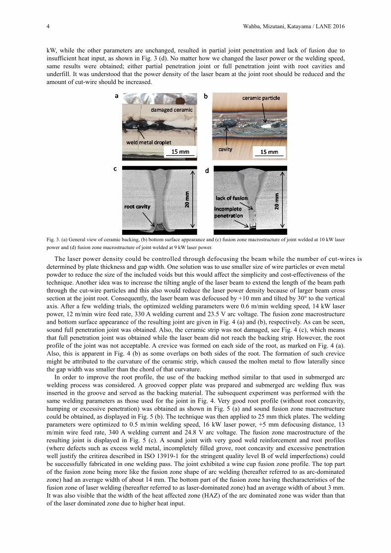
First group of experiments was conducted on 20 mm thick plates using ceramic backing method. Processing parameters had to be optimized in order to obtain full penetration joints and in the same time avoid any direct contact between the laser beam and the backing material. At 10 kW laser power, the welding process was unstable, a large number of spatters was generated and melt expulsion occurred recurrently. The ceramic strip was damaged and some ceramic pieces were found attached to the joint root, as can be seen in Fig. 3 (a) and (b). This implies that the laser beam interacted with the ceramic backing and the resulting plume destabilized the molten pool leading to spatter formation and root cavities, as shown in Fig. 3 (c). Reducing the laser power to 9
4 Wahba, Mizutani, Katayama / LANE 2016
kW, while the other parameters are unchanged, resulted in partial joint penetration and lack of fusion due to insufficient heat input, as shown in Fig. 3 (d). No matter how we changed the laser power or the welding speed, same results were obtained; either partial penetration joint or full penetration joint with root cavities and underfill. It was understood that the power density of the laser beam at the joint root should be reduced and the amount of cut-wire should be increased.
Fig. 3. (a) General view of ceramic backing, (b) bottom surface appearance and (c) fusion zone macrostructure of joint welded at 10 kW laser
power and (d) fusion zone macrostructure of joint welded at 9 kW laser power.
The laser power density could be controlled through defocusing the beam while the number of cut-wires is determined by plate thickness and gap width. One solution was to use smaller size of wire particles or even metal powder to reduce the size of the included voids but this would affect the simplicity and cost-effectiveness of the technique. Another idea was to increase the tilting angle of the laser beam to extend the length of the beam path through the cut-wire particles and this also would reduce the laser power density because of larger beam cross section at the joint root. Consequently, the laser beam was defocused by +10 mm and tilted by 30° to the vertical axis. After a few welding trials, the optimized welding parameters were 0.6 m/min welding speed, 14 kW laser power, 12 m/min wire feed rate, 330 A welding current and 23.5 V arc voltage. The fusion zone macrostructure and bottom surface appearance of the resulting joint are given in Fig. 4 (a) and (b), respectively. As can be seen, sound full penetration joint was obtained. Also, the ceramic strip was not damaged, see Fig. 4 (c), which means that full penetration joint was obtained while the laser beam did not reach the backing strip. However, the root profile of the joint was not acceptable. A crevice was formed on each side of the root, as marked on Fig. 4 (a). Also, this is apparent in Fig. 4 (b) as some overlaps on both sides of the root. The formation of such crevice might be attributed to the curvature of the ceramic strip, which caused the molten metal to flow laterally since the gap width was smaller than the chord of that curvature.
In order to improve the root profile, the use of the backing method similar to that used in submerged arc welding process was considered. A grooved copper plate was prepared and submerged arc welding flux was inserted in the groove and served as the backing material. The subsequent experiment was performed with the same welding parameters as those used for the joint in Fig. 4. Very good root profile (without root concavity, humping or excessive penetration) was obtained as shown in Fig. 5 (a) and sound fusion zone macrostructure could be obtained, as displayed in Fig. 5 (b). The technique was then applied to 25 mm thick plates. The welding parameters were optimized to 0.5 m/min welding speed, 16 kW laser power, +5 mm defocusing distance, 13 m/min wire feed rate, 340 A welding current and 24.8 V arc voltage. The fusion zone macrostructure of the resulting joint is displayed in Fig. 5 (c). A sound joint with very good weld reinforcement and root profiles (where defects such as excess weld metal, incompletely filled grove, root concavity and excessive penetration well justify the critirea described in ISO 13919-1 for the stringent quality level B of weld imperfections) could be successfully fabricated in one welding pass. The joint exhibited a wine cup fusion zone profile. The top part of the fusion zone being more like the fusion zone shape of arc welding (hereafter referred to as arc-dominated zone) had an average width of about 14 mm. The bottom part of the fusion zone having thecharacteristics of the fusion zone of laser welding (hereafter referred to as laser-dominated zone) had an average width of about 3 mm. It was also visible that the width of the heat affected zone (HAZ) of the arc dominated zone was wider than that of the laser dominated zone due to higher heat input.

5 Wahba, Mizutani, Katayama / LANE 2016
Fig. 4. Hybrid welding with ceramic backing at optimized parameters; (a) fusion zone macrostructure, (b) bottom surface appearance and (c)
general view of ceramic backing strip.
Fig. 5. Hybrid welding with flux backing method at optimized parameters; (a) bottom surface appearance and (b) fusion zone macrostructure
of 20 mm thick joint and (c) fusion zone macrostructure of one-side welded 25 mm thick I-butt joint.
3.2. Mechanical properties of the welded joints
Tensile test specimens were prepared from the top and bottom parts of the joint representing the arc-dominated zone and the laser-dominated, respectively. All tested specimens failed in the base material, indicating a higher strength of the joint. Similarly, impact test specimens were machined from the top and bottom parts of the joint and tested at –20° C. The average impact toughness of the top part was 105 J and the average impact toughness of the bottom part was 147 J. Although the impact toughness of the weld metal in general was less than that of the base material, 195 J, it was still well above the minimum value (27 J) set by the industrial standard.
Next, microhardness measurements were performed on a transverse cross section of the welded joint. The average hardness of the arc-dominated zone and the laser-dominated zone were HV 224 and HV 253, respectively. Meanwhile, the average hardness of the base material was HV 168. The maximum hardness value measured was HV 306 in the heat affected zone of the root. This is smaller than the maximum value set by the relevant standard (HV 350).
3.2. Double-side welding of 50 mm thick plates
Finally, an attempt was made to weld 50 mm thick plates. Work pieces were first assembled by tack welding, fiberglass tape was attached to the bottom side as backing and cut-wire particles were inserted into the gap. Hybrid laser-arc welding was performed on the top side, the joint was turned upside down, the fiberglass tape was removed, and the second hybrid laser-arc welding pass was laid. The fusion zone macrostructure of the resulting joint is shown in Fig. 6. A very good butt joint of 50 mm thick plates could be fabricated in only two welding passes without edge preparation and with very simple welding technique. It should be noted here that any type of backing material could be used since the laser beam did not fully penetrate the joint in the first pass. This would add to the simplicity of the proposed technique. Also, double-side welding technique would be a simple alternative in the case if the available laser power level is not as high as that used in this investigation.

6 Wahba, Mizutani, Katayama / LANE 2016
Fig. 6. Fusion zone macrostructure of double-side welded 50 mm thick I-butt joint.
The results presented above confirm that the proposed technique enhances the capabilities of the hybrid laser-arc welding process in several aspects. First, very thick plates of 25 mm thickness or more could be welded in one or two passes. Sound root formation is no longer a problem for such thick plates as it is the case for laser welding (Ilar et al., 2012). Another important aspect is that the new technique eliminated the step of groove machining, which is both time and money consuming. Furthermore, with double-side welding even thicker joints up to 50 mm in thickness can be fabricated very simply. Finally, the consumables used in the welding process are commercially available at low cost.
As for the edge quality of the joints, this technique has been successfully applied to machined edges as well as saw-cut edges. However, no attempt has so far been made to weld gas- or laser-cut joints.
4. Summary
In this study, a novel technique was developed to one-pass weld 25 mm thick plates in I-butt joint configuration. A backing method (submerged arc welding flux, ceramic strip or fiberglass tape) was used to support the joint during welding. A square groove butt joint was prepared with 2.5 mm air gap. Cut-wire particles were inserted into the gap. Then, hybrid laser-arc welding was performed. Laser power density at the joint root was optimized to obtain full penetration without affecting the backing material. The resulting joints were defect-free and possessed good mechanical properties conforming to the relevant industrial standards. The technique was then successfully applied to double-side weld 50 mm thick I-butt joints in a very simple manner.
References
Ilar Torbjorn, Eriksson Ingemar, Powell John, Kaplan Alexander, 2012. Root humping in laser welding – an investigation based on high speed imaging. Physics Procedia 39, 27-32.
Katayama Seiji, Abe Yohei, Mizutani Masami, Kawahito Yousuke, 2011. Development of deep penetration welding technology with high brightness laser under vacuum. Physics Procedia 12, 75–80.
Kristensen, J.K., Webster, S., Petring, D., 2009. Hybrid laser welding of thick section steels - the HYBLAS project, 12th NOLAMP Conference 2009, Nordic Laser Materials Processing Conference. Copenhagen, Denmark, CD-ROM.
Reisgen Uwe, Olschok Simon, Jakobs Stefan, 2014. Laser submerged arc welding (LUPuS) with solid state lasers. Physics Procedia 56, 653 – 662.
Tsukamoto Takeshi, Kawanaka Hirotsugu, Maeda Yoshihisa, 2011. Laser narrow gap welding of thick carbon steels using high brightness laser with beam oscillation. 30th ICALEO Conference 2011, International Congress on Application of Lasers and Electro-Optics. Florida, USA, CD-ROM.
Turichina, G., Kuznetsova, M., Sokolov, M., Salminen, A., 2015. Hybrid laser arc welding of X80 steel: influence of welding speed and preheating on the microstructure and mechanical properties. Physics Procedia 78, 35 – 44.
Wahba, M., Mizutani, M., Katayama, S., 2015. Hybrid Welding with Fiber Laser and CO2 Gas Shielded Arc. Journal of Materials Processing Technology 221, 146-153.
Wahba Mohamed, Mizutani Masami, Katayama Seiji, 2015. Development of Hybrid Laser-Arc Welding With CO2 Shielding Gas. 7th International Congress on Laser Advanced Materials Processing. Kita Kyushu, Japan.