hybrid effects of stirrup ratio and steel fibers on …
TRANSCRIPT
��
HYBRID EFFECTS OF STIRRUP RATIO AND STEEL FIBERS ON SHEAR BEHAVIOUR OF SELF-COMPACTING
CONCRETE
PRAVEEN KANNAM1, VENKATESWARA RAO. SARELLA2,
RATHISH KUMAR PANCHARATHI3
�
Shear cracking behaviour of fibrous self-compacting concrete of normal and high strength grade (M30 and M70) is presented
here. Two stirrup diameters (6mm � and 8 mm �) with a constant steel fiber content of 38 kg/m3 (0.5% by volume of concrete)
were selected for the present study. The size of the beam was fixed at 100x200x1200mm. The clear span of the beam 1100mm,
was maintained throughout the study. A total of 16 shear-deficient beams were tested under three point loading. Two stirrup
spacing (180mm and 360 mm) are used for the shear span-to-depth ratio (a/d = 2). Investigation indicates that initial cracking
load and ultimate load increased as the area of shear reinforcement increased by increasing the diameter of stirrup. It was also
noted that the failure mode was modified from brittle shear failure to flexural-shear failure in the presence of fibers. The
mechanical behaviour of SFRSCC was improved due to the combined effect of stirrups and steel fibers. The stiffness,
toughness, and deflection of the beams increased when compared to SCC beams without fibers. The experimental results were
compared with existing models available in literature, and the correlation is satisfactory.
Keywords: self Compacting Concrete, Shear Failure, Reinforced Concrete (RC),�flexural-shear failure.
���������������������������������������� ���������������������Research Scholar, Department of Civil Engineering, National Institute of Technology, Warangal, India. [email protected] �� Associate Professor, Department of Civil Engineering, National Institute of Technology, Warangal, India. � Professor, Department of Civil Engineering, National Institute of Technology, Warangal, India. �
��
1. INTRODUCTION
When a reinforced concrete beam (RC) is subjected to a combined effect of bending and shear force,
beams with lower shear-resisting capacity fail early, even before its full strength is achieved. These types
of shear failure are sudden and brittle, as they occur without any warning. To prevent these types of shear
failures, beams are reinforced with stirrups. The addition of steel fibers can modify the failure pattern
and can also increase shear strength [1]. If a sufficient amount of steel fibers are present in a reinforced
concrete member, it can bridge the crack width and can also increase the post-cracking behaviour of the
member [2]. Steel fibers can also partially replace stirrups, which can eliminate congestion of
reinforcements near beam column joints, thereby reducing the cost of longitudinal reinforcement [3, 4].
The difference between steel fiber-reinforced self-compacting concrete (SFRSCC) and fiber-reinforced
concrete (FRC) is that the addition of steel fibers reduces the fresh properties of self-compacting concrete,
whereas inclusions of fibers in fibrous concrete can enhance the post-cracking behaviour. Thus, SFRSCC
has the advantages of both SCC and FRC [5]. The key parameters influencing the shear behaviour of
reinforced concrete beams are: shear span-to-effective depth ratio (a/d), grade of concrete (fck),
longitudinal reinforcement (lt), area of shear reinforcement (Asv) and volume of fibers (Vf) [6].� �The
difference between steel fiber-reinforced self-compacting concrete (SFRSCC) and traditional fiber
reinforced concrete (FRC) is that the fiber content of FRC is mainly determined by the post-cracking
behaviour, and the fiber content of SFRSCC is mainly restricted by the workability of fresh SCC [7,8].
SFRSCC combines the advantages of both SCC and FRC. However, research on the study of SFRSCC
beams, especially on the shear behaviour of SFRSCC, is still limited.
The present study shows the experimental results conducted on SFRSCC beams. The main objective of
this study is to understand the shear behaviour of SFRSCC beams for different stirrup diameters and
spacing for both lower and higher concrete grades (M30 & M70), and also to analyze the influence of
steel fibers on self-compacting concrete.
2. RESEARCH SIGNIFICANCE
Plain concrete is considered a brittle material with very low tensile strength and shear capacity. The
inclusion of steel fibers into concrete mix improves ductility and toughness and can also bridge cracks
and reduce crack propagation, so possibility of sudden failure can be eliminated, enhancing shear
PRAVEEN KANNAM, VENKATESWARA RAO SARELLA, RATHISH KUMAR PANCHARATHI146
��
strength. As the interactions between concrete and steel fibers are complex, it is difficult to predict the
increase in shear strength. Hence, an accurate model for predicting shear strengths of fibrous concretes
is needed, enabling design engineers to use steel fibers as a commonplace building material. Work
available from literature on predicting shear behaviour of SCC is scant, and the available models need to
be supplemented with further experimental work to compensate for this.
2.1 MATERIALS USED AND METHODS 2.1.1 CEMENT
The cement used in the investigation was 53 Grade Ordinary Portland cement confirming to IS: 12269
[9]. The specific gravity of the cement was found to be 3.10 and the initial and final setting times were
45 and 560 min, respectively.
2.1.2 FLY ASH
Fly ash confirming to IS: 3812 [10] was used as mineral admixture. The fly ash used in the present study
was obtained from NTPC Ramagundam and is of Class F. The specific gravity of fly ash used in the
present study was 2.2.
2.1.3 FINE AGGREGATE (FA)
The fine aggregate used in the present study conforms to Zone-2 according to IS: 383 [11]. It was
obtained from a nearby river source. The specific gravity was 2.65, while the bulk density of the sand
was 1450 Kg/m3.
2.1.4 COARSE AGGREGATE (CA)
Crushed granite was used as a coarse aggregate. Coarse aggregates of 20 mm nominal size were obtained
from a local crushing unit; it was well-graded aggregate according to IS: 383 [11]. The specific gravity
was 2.8, while the bulk density was 1500 Kg/m3.
2.1.5 WATER
Potable water was used in the experimental work for both mixing and curing of specimens.
2.1.6 SILICA FUME [12]
Silica fume is an ultrafine powder with an average particle diameter of 150 nm which was used in the
present study. The specific gravity of silica fume is generally in the range of 2.2 to 2.3, and its specific
surface area ranges from 15,000 to 30,000 m2/ kg.
HYBRID EFFECTS OF STIRRUP RATIO AND STEEL FIBERS ON SHEAR BEHAVIOUR... 147

��
2.1.7 SUPER PLASTICIZER (SP)
In the present study, a polycarboxylic ether-based high range water-reducing admixture confirming to
ASTM C494 [13] obtained from Chyrso Chemicals, India, commonly called a super plasticizer was used.
The major advantage of using a super plasticizer is improving the flowing ability of high-performance
concretes at lower water-cement ratios.
2.1.8 STEEL FIBER [14]
Crimped steel fibers (from Apex Encon Projects Pvt, Ltd., New Delhi, India) with a nominal fiber
diameter of 0.5mm and a cut length of 30mm with an aspect ratio of 60 were used. The tensile strength
and modulus of elasticity of this fiber is 850 MPa and 2.1x10⁵ MPa, respectively.
2.1.9 TENSION REINFORCEMENT
TMT bars 12 and 16 mm diameter of Fe 500 grade confirming to IS: 1786 [15] whose yield strength was
500 N/mm2 and length 1160mm were used as tension reinforcements, and 6mm Ø mild steel bars whose
yield strength was 290 N/mm2 were used as top compression reinforcements. Two-legged 6mm Ø mild
steel bars whose yield strength was 290 N/mm2 and two-legged 8mm Ø TMT bars whose yield strength
was 290 N/mm2 were used as stirrups (shear reinforcement).
2.2 EXPERIMENTAL PROGRAMME
In the present study, a total of 16 shear-deficient beams were designed and cast for two grades of SCC,
M30 and M70. Two stirrup diameters of 6 and 8mm were used to study the effects of stirrup diameter
and two stirrup spacing markers were considered (180mm and 360mm) to study the effects of stirrup
spacing on shear behaviour. The dimensions of the beam were fixed as 100x200x1200mm with a clear
span of 1100mm. All beams were tested under three-point loading.
For compressive strength, standard cast iron cube moulds measuring 150mm x 150mm x 150mm were
used. For split tensile strength, standard cast iron cylinder moulds measuring 150mm � x 300mm were
used. For flexural strength, a 100mm x 100mm x 500mm standard prism mould was used. For all the
above tests, the average of three specimens were considered. In the present study, the proportion of steel
fibers is taken as 0.5% to the volume of concrete [16].
Table 1 shows the details of the beams with different spacing of stirrups, and percentage of steel fibers
per volume of concrete.
PRAVEEN KANNAM, VENKATESWARA RAO SARELLA, RATHISH KUMAR PANCHARATHI148
��
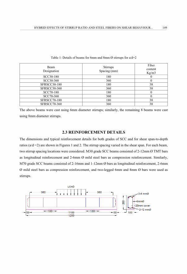
Table 1: Details of beams for 6mm and 8mm Ø stirrups for a/d=2
Beam Designation
Stirrups Spacing (mm)
Fibercontent Kg/m3
SCC30-180 180 0SCC30-360 360 0
SFRSCC30-180 180 38SFRSCC30-360 360 38
SCC70-180 180 0SCC70-360 360 0
SFRSCC70-180 180 38SFRSCC70-360 360 38
The above beams were cast using 6mm diameter stirrups; similarly, the remaining 8 beams were cast
using 8mm diameter stirrups.
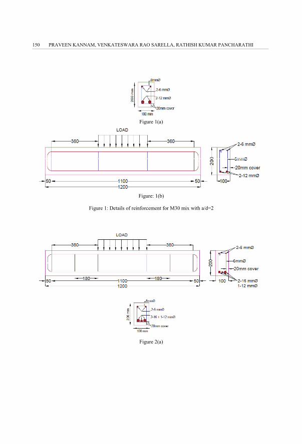
2.3 REINFORCEMENT DETAILS The dimensions and typical reinforcement details for both grades of SCC and for shear span-to-depth
ratios (a/d =2) are shown in Figures 1 and 2. The stirrup spacing varied in the shear span. For each beam,
two stirrup spacing locations were considered. M30 grade SCC beams consisted of 2-12mm Ø TMT bars
as longitudinal reinforcement and 2-6mm Ø mild steel bars as compression reinforcement. Similarly,
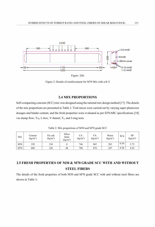
M70 grade SCC beams consisted of 2-16mm and 1-12mm Ø bars as longitudinal reinforcement, 2-6mm
Ø mild steel bars as compression reinforcement, and two-legged 6mm and 8mm Ø bars were used as
stirrups.��
HYBRID EFFECTS OF STIRRUP RATIO AND STEEL FIBERS ON SHEAR BEHAVIOUR... 149
��
Figure 1(a)
Figure: 1(b)
Figure 1: Details of reinforcement for M30 mix with a/d=2
Figure 2(a)
PRAVEEN KANNAM, VENKATESWARA RAO SARELLA, RATHISH KUMAR PANCHARATHI150
��
Figure: 2(b)
Figure 2: Details of reinforcement for M70 Mix with a/d=2
2.4 MIX PROPORTIONSSelf-compacting concrete (SCC) mix was designed using the rational mix design method [17]. The details
of the mix proportions are presented in Table 2. Trial mixes were carried out by varying super plasticizer
dosages and binder content, and the fresh properties were evaluated as per EFNARC specifications [18]
via slump flow, T50, L-box, V-funnel, T5, and J-ring tests.
Table 2: Mix proportions of M30 and M70 grade SCC
Mix Cement (kg/m3)
Fly ash (kg/m3)
Silica fume
(kg/m3)
CA (kg/m3)
FA (kg/m3)
Water (kg/m3)
W/b SP (kg/m3)
M30 350 324 0 746 945 203 0.30 5.73 M70 600 226 48 780 874 247 0.28 6.03
2.5 FRESH PROPERTIES OF M30 & M70 GRADE SCC WITH AND WITHOUT
STEEL FIBERS The details of the fresh properties of both M30 and M70 grade SCC with and without steel fibers are
shown in Table 3.
HYBRID EFFECTS OF STIRRUP RATIO AND STEEL FIBERS ON SHEAR BEHAVIOUR... 151

��
Table 3: Fresh properties of M30 and M70 grade SCC without and with fiber
Grade of Concrete M30 M70 EFNARC 2005 Dosage of Fibers 0% 0.5% 0% 0.5% Min. Max. Slump Test (mm) 750 620 720 680 550 800
T50 Slump Flow (sec) 3 5 2.5 4 2 5 V-Funnel (sec) 6 6.5 10.5 11.8 6 12
V-Funnel @ T5 min (sec) 7.5 8.3 12 14 6 15 J-ring (sec) 3 8 3 7 0 10
It can be seen from Table 3 that the addition of steel fibers has reduced flow properties, though it still
satisfies EFNARC (European Federation of National Associations Representing for Concrete)
specifications. Figure 3 shows the various tests conducted on the workability of SCC.
a) Slump flow b) J-ring c) V-funnel
Figure 3: Some tests on the workability of SCC
2.6 HARDENED PROPERTIES OF SELF-COMPACTING CONCRETE WITH
AND WITHOUT STEEL FIBERS
Details of the hardened properties of the M30 and M70 grades of SCC with and without steel fibers at
the age of 28 days are shown in Table 4. All the tests were done as per IS: 516 [19] specifications.
PRAVEEN KANNAM, VENKATESWARA RAO SARELLA, RATHISH KUMAR PANCHARATHI152
��
Table 4: Hardened properties of M30 and M70 grades of SCC at 28 days
M30 M70
Dosage of Steel Fibers
Compressive Strength (MPa)
Split Tensile Strength (MPa)
Flexural Strength (MPa)
Compressive Strength (MPa)
Split Tensile Strength (MPa)
Flexural Strength (MPa)
0% 39.67 4.17 3.98 78.25 5.04 5.34 0.5% 48.76 4.34 4.87 86.66 5.85 6.41
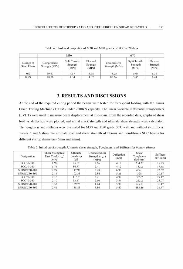
3. RESULTS AND DISCUSSIONSAt the end of the required curing period the beams were tested for three-point loading with the Tinius
Olsen Testing Machine (TOTM) under 2000kN capacity. The linear variable differential transformers
(LVDT) were used to measure beam displacement at mid-span. From the recorded data, graphs of shear
load vs. deflection were plotted, and initial crack strength and ultimate shear strength were calculated.
The toughness and stiffness were evaluated for M30 and M70 grade SCC with and without steel fibers.
Tables 5 and 6 show the ultimate load and shear strength of fibrous and non-fibrous SCC beams for
different stirrup diameters (6mm and 8mm).
Table 5: Initial crack strength, Ultimate shear strength, Toughness, and Stiffness for 6mm � stirrups
Designation Shear Strength at First Crack (���)
(MPa)
Ultimate Load (vu)
kN
Ultimate Shear Strength (��� )
(MPa)
Deflection (mm)
Shear Toughness (kN-mm)
Stiffness (kN/mm)
SCC30-180 1.98 95.67 2.66 4.18 234.27 18.23 SCC30-360 1.76 86.77 2.41 4.12 182.2 17.68
SFRSCC30-180 2.29 117.92 3.28 6.90 464.1 22.52 SFRSCC30-360 2.16 102.35 2.84 5.21 328 20.17
SCC70-180 2.16 115.7 3.21 4.92 365.7 29.17 SCC70-360 2.10 93.67 2.60 3.54 212.2 28.07
SFRSCC70-180 3.52 159.75 4.44 5.90 525.03 36.47 SFRSCC70-360 2.41 138.83 3.86 5.40 483.46 31.47
HYBRID EFFECTS OF STIRRUP RATIO AND STEEL FIBERS ON SHEAR BEHAVIOUR... 153

��
Table 6: Initial crack strength, Ultimate shear strength, Toughness, and Stiffness for 8mm � stirrups
Designation Shear Strength at First Crack (���)
(MPa)
Ultimate Load (vu)
kN
Ultimate Shear Strength (��� )
(MPa)
Deflection (mm)
Shear Toughness (kN-
mm)
Stiffness (kN/mm)
SCC30-180 2.17 113.62 3.16 3.90 252 29.58 SCC30-360 1.49 100.65 2.80 3.64 144 28.58
SFRSCC30-180 2.42 127.04 3.53 5.24 436 34.41 SFRSCC30-360 1.93 122.57 3.40 4.52 318 30.52
SCC70-180 2.80 174.59 4.85 9.82 1471 37.37 SCC70-360 2.39 143.15 3.98 5.20 513 33.53
SFRSCC70-180 3.17 199.06 5.53 5.32 1588 51.70 SFRSCC70-360 2.67 158.80 4.41 5.63 586 38.01
3.1 EFFECTS OF STIRRUP DIAMETER ON SHEAR STRENGTH OF SFRSCC
BEAMS
The effects of stirrup diameter size on shear strength (���= ����) are shown in Figs. 4 and 5. It can be
observed from Tables 5 and 6 that as the area of shear reinforcement increases, ultimate load and
ultimate shear strengths also increases.
1. For constant stirrup spacing, the load-carrying capacity of beam SCC30-180 with an 8mm diameter
stirrup is 18.8% higher compared to that of a similar beam with a 6mm diameter.
2. Similarly, for the beams with the higher grade of concrete for constant spacing of the stirrup, i.e.
SCC70-180 with an 8mm diameter stirrup, the load-carrying capacity is higher than that of the beam
with a 6 mm diameter.
3. Similarly, the addition of fibers for constant spacing of a stirrup has increased shear strength by 8%
for M30 grade concrete with the 8mm stirrup diameter, compared to the 6mm diameter, whereas for
the higher grade of concrete, M70, shear strength increased by 24.5%.
4. For beam SFCC30-180 with the 6mm diameter, shear strength increased slightly, by 3.5%, compared
to the beam with no fibers and with the 8 mm diameter stirrup. Similarly, for the beam with the higher
grade of concrete, SFSCC70-180 with the 6mm diameter, shear strength decreased slightly, by 8.4%,
compared to the beam with no fibers and with the 8mm diameter stirrup.
5. The combination of fibers and stirrups has shown a positive hybrid effect on the shear strength of
self-compacting concrete.
6. Beam toughness also increased with the addition of stirrups and steel fibers.
PRAVEEN KANNAM, VENKATESWARA RAO SARELLA, RATHISH KUMAR PANCHARATHI154

��
Figure 4: Shear strength vs. stirrup diameter for 180 mm spacing
Figure 5: Shear strength vs. stirrup diameter for 360 mm spacing
����
�����������
����
���
��
�
�
�
�
�
��� ���
���
�� ����
�������
���������������
�������� � �������� �������� � ��������
���
������
��
���
��������
��
�
�
�
�
��� ���
���
�� ����
�������
����������������
�������� � �������� �������� � ��������
HYBRID EFFECTS OF STIRRUP RATIO AND STEEL FIBERS ON SHEAR BEHAVIOUR... 155

��
Figure 6: Toughness vs. stirrup spacing for 6mm � stirrup
Figure 7: Toughness vs. stirrup spacing for 8mm � stirrup
�����
�����
����
�����
�
���
����
����
�
���
���
���
��
��
���
��� ���
!��
���""�#
$��
�
������� ��%�������
���� ���� �& ���� �& ����
���
�����
���
��
���
��
�
���
��
���
���
����
����
���
����
����
��� ���
!��
���""��#$
���
������� ��%�������
���� �& ���� ���� �& ����
PRAVEEN KANNAM, VENKATESWARA RAO SARELLA, RATHISH KUMAR PANCHARATHI156
��
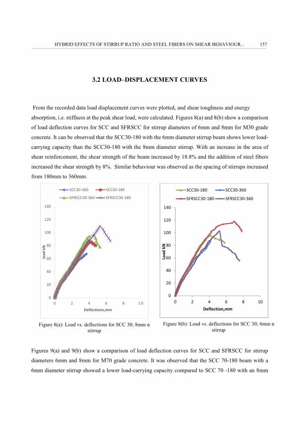
3.2 LOAD–DISPLACEMENT CURVES
From the recorded data load displacement curves were plotted, and shear toughness and energy
absorption, i.e. stiffness at the peak shear load, were calculated. Figures 8(a) and 8(b) show a comparison
of load deflection curves for SCC and SFRSCC for stirrup diameters of 6mm and 8mm for M30 grade
concrete. It can be observed that the SCC30-180 with the 6mm diameter stirrup beam shows lower load-
carrying capacity than the SCC30-180 with the 8mm diameter stirrup. With an increase in the area of
shear reinforcement, the shear strength of the beam increased by 18.8% and the addition of steel fibers
increased the shear strength by 8%. Similar behaviour was observed as the spacing of stirrups increased
from 180mm to 360mm.
Figure 8(a): Load vs. deflections for SCC 30; 8mm �stirrup
Figure 8(b): Load vs. deflections for SCC 30; 6mm �stirrup
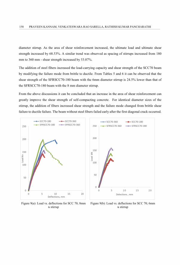
Figures 9(a) and 9(b) show a comparison of load deflection curves for SCC and SFRSCC for stirrup
diameters 6mm and 8mm for M70 grade concrete. It was observed that the SCC 70-180 beam with a
6mm diameter stirrup showed a lower load-carrying capacity compared to SCC 70 -180 with an 8mm
�
��
�
��
��
���
���
��
� � � � ��
����
���
��� �������
�������� ��������
�& �������� �& ��������
�
��
�
��
��
���
���
��
� � � � ��
����
���
��� ������
�������� ��������
�& �������� �& ��������
HYBRID EFFECTS OF STIRRUP RATIO AND STEEL FIBERS ON SHEAR BEHAVIOUR... 157
��
diameter stirrup. As the area of shear reinforcement increased, the ultimate load and ultimate shear
strength increased by 68.53%. A similar trend was observed as spacing of stirrups increased from 180
mm to 360 mm - shear strength increased by 53.07%.
The addition of steel fibers increased the load-carrying capacity and shear strength of the SCC70 beam
by modifying the failure mode from brittle to ductile. From Tables 5 and 6 it can be observed that the
shear strength of the SFRSCC70-180 beam with the 6mm diameter stirrup is 24.5% lower than that of
the SFRSCC70-180 beam with the 8 mm diameter stirrup.
From the above discussions it can be concluded that an increase in the area of shear reinforcement can
greatly improve the shear strength of self-compacting concrete. For identical diameter sizes of the
stirrup, the addition of fibers increased shear strength and the failure mode changed from brittle shear
failure to ductile failure. The beam without steel fibers failed early after the first diagonal crack occurred.
Figure 9(a): Load vs. deflections for SCC 70; 8mm � stirrup
Figure 9(b): Load vs. deflections for SCC 70; 6mm � stirrup
�
�
���
��
���
��
� �� � ��
'!�(
�)�
��*+�%��!�"����
�������� �������� �& �������� �& ��������
�
�
���
��
���
��
� �� � ��
'!�(
��#$
��+�%��!�"�����
�������� ��������
�& �������� �& ��������
PRAVEEN KANNAM, VENKATESWARA RAO SARELLA, RATHISH KUMAR PANCHARATHI158
��
4. COMPARISON OF TEST RESULTS WITH MODELS FROM
LITERATURE
The experimental results obtained from the ultimate shear strength tests of non-fibrous SCC and fibrous
SCC are compared with shear strength models available for vibrated concrete below.
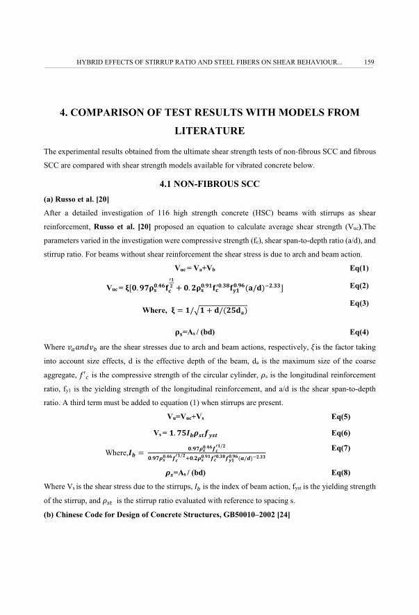
4.1 NON-FIBROUS SCC (a) Russo et al. [20]
After a detailed investigation of 116 high strength concrete (HSC) beams with stirrups as shear
reinforcement, Russo et al. [20] proposed an equation to calculate average shear strength (Vuc).The
parameters varied in the investigation were compressive strength (fc), shear span-to-depth ratio (a/d), and
stirrup ratio. For beams without shear reinforcement the shear stress is due to arch and beam action.
Vuc = Va+Vb Eq(1)
Vuc = �� ������������ � �� ����� ������������� ���� !"����# Eq(2)
Where, $ ��%� � ���& �! Eq(3)
��=As / (bd) Eq(4)
Where '()*+'� are the shear stresses due to arch and beam actions, respectively, ,is the factor taking
into account size effects, d is the effective depth of the beam, da is the maximum size of the coarse
aggregate, -.� is the compressive strength of the circular cylinder, /s is the longitudinal reinforcement
ratio, fy1 is the yielding strength of the longitudinal reinforcement, and a/d is the shear span-to-depth
ratio. A third term must be added to equation (1) when stirrups are present.
Vu=Vuc+Vs Eq(5)
Vs = �� �&012345634 Eq(6)
Where,01 $ 7 �� �23����58������ �23����58����9���23�� �58�����56��� ��:�;!<����
Eq(7)
23=As / (bd) Eq(8)
Where Vs is the shear stress due to the stirrups, =�7is the index of beam action, fyst is the yielding strength
of the stirrup, and />? is the stirrup ratio evaluated with reference to spacing s.
(b) Chinese Code for Design of Concrete Structures, GB50010–2002 [24]
HYBRID EFFECTS OF STIRRUP RATIO AND STEEL FIBERS ON SHEAR BEHAVIOUR... 159

��
After a detailed investigation of beams with different grades of concrete and stirrups ratios, Chinese
code [23] proposed an equation for vibrated concrete to calculate the shear strength:
@A $ ���&�9B 541; � 5634 C343 ; ,
Eq(9)
DE $ @E1;
Eq(10)
Here, F� is the shear load of the RC member, -?is the tensile strength of the prism, Gis the shear span-
to-depth ratio, '� is the shear strength of the RC member, and s is spacing(c) ACI code 318-14 [25]
After a detailed investigation of beams with different grades of concrete, different yield strengths, and
stirrups ratio, ACI committee 318 has given an equation to calculate shear strength for vibrated concrete
DE $ �� HI5�8 � ���23 J;:KL � 2345634
Eq(11)
where DE is the shear strength, -�� is the average compressive strength of concrete, /st is the longitudinal
reinforcement ratio, -M>? is the yielding strength of the longitudinal reinforcement, and a/d is the shear
span-to-depth ratio.
(d) EURO Code-2 [26]
A design equation specified by Eurocode 2 (2004) for shear resistance (VRdc) of the members without
shear reinforcement is as follows:
VRdc = CRd,c * k* [��� N 234 N 758O#1/3 * bw *d Eq(12)
where, CRd,c = Co-efficient derived from tests = P�QRST = 0.12
k = Size factor = 1+IUPP�
fck = Characteristic concrete compressive strength at 28 days
bw = Smallest web width,
d= Effective depth of cross-section
/st = VWX�Y�7is the longitudinal reinforcement ratio
For reinforced concrete members with vertical shear reinforcement, shear resistance,
PRAVEEN KANNAM, VENKATESWARA RAO SARELLA, RATHISH KUMAR PANCHARATHI160
��
VRd, s, should be taken to lower, either
VRd, s = C3Z3 7[756 �\]^ Eq (13)
Or
VRd, s max =7_81Z7[7D758;�\] ^9 ]�`^ Eq(14)
where VRd,s is the design value of the shear force which can be sustained by the yielding shear
reinforcement; VRd,max is the design value of the maximum shear force which can be sustained by the
member (limited by crushing of the compression struts), Asw is the cross-sectional area of the shear
reinforcement; s is the spacing of the stirrups; Z is the lever arm (which may be considered as Z= 0.9d),
fy is the yield strength of the shear reinforcement, a7is the angle of the inclined struts, bw is the width of
the web, fcd is the design of the compressive cylinder strength of concrete at 28 days, and _8 is a
coefficient which takes into account the effect of normal stresses on shear strength. The recommended
value of _8 is 1 for non-prestressed structures and 1.25 for prestressed structures.
Also, ' is a coefficient which takes into account the increase in fragility and the reduction of shear
transfer by aggregate interlock with an increase of the compressive concrete strength. It may be assumed
to be 0.6 for fck � 60 MPa, and 0.92 - fck/200 b0.5 for high strength concrete beams.
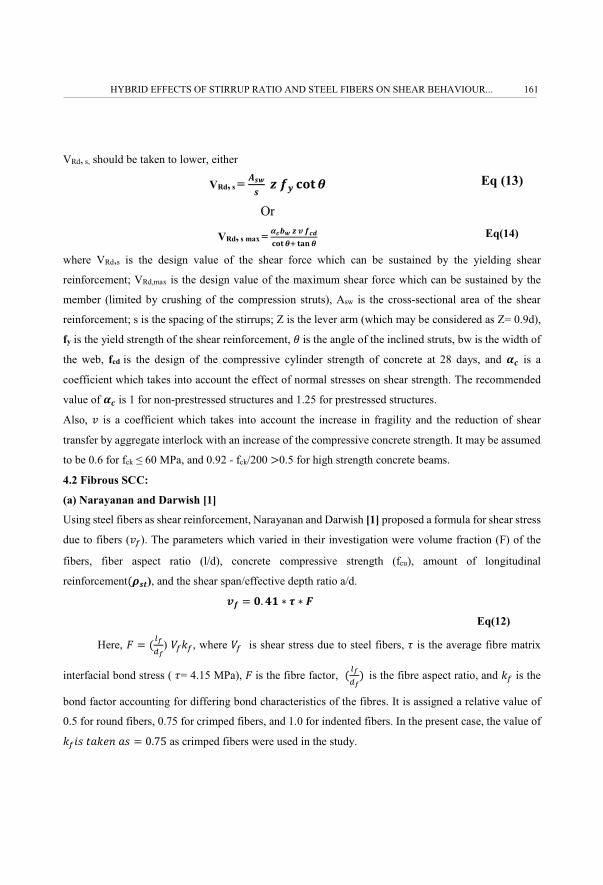
4.2 Fibrous SCC:
(a) Narayanan and Darwish [1]
Using steel fibers as shear reinforcement, Narayanan and Darwish [1] proposed a formula for shear stress
due to fibers ('c). The parameters which varied in their investigation were volume fraction (F) of the
fibers, fiber aspect ratio (l/d), concrete compressive strength (fcu), amount of longitudinal
reinforcement�234), and the shear span/effective depth ratio a/d.
D5 $ �� �� N d N e
Eq(12)
Here, f $ �gh�h) Fcic, where Fc is shear stress due to steel fibers, � is the average fibre matrix
interfacial bond stress ( �= 4.15 MPa), f7is the fibre factor, � gh�h!77is the fibre aspect ratio, and ic is the
bond factor accounting for differing bond characteristics of the fibres. It is assigned a relative value of
0.5 for round fibers, 0.75 for crimped fibers, and 1.0 for indented fibers. In the present case, the value of
icjk7l)im*7)k $ n�op as crimped fibers were used in the study.
HYBRID EFFECTS OF STIRRUP RATIO AND STEEL FIBERS ON SHEAR BEHAVIOUR... 161

��
(b) Ta’an and Feel [21]
A model was proposed to predict the ultimate shear strength of fiber-reinforced concrete rectangular
beams by Ta’an and Feel [21]. A total of 89 beams were tested; all failed in shear. The factors
influencing the shear strength of fiber concrete beams were found to be the shear span-to-depth ratio,
main reinforcement volume, dimensions, and type.
D5 $ J�� & K N O N @5 N � q5;5! Eq(13)
Here, k is a factor reflecting the fiber shape. For crimped fibers, k = 0.75,Fc is the fibre volume fraction
and 7� gh�h!7is the fibre aspect ratio.
(c) Swamy et al. [22]
To assess the effectiveness of steel fibers used as shear reinforcement in lightweight concrete beams,
Swamy et al. [22] have proposed a truss model to predict ultimate shear strength,
D5 $ �� �� N d N @5 N �q5;5)
Eq(14)
where �is equal to 4.15 MPa, as suggested by Narayanan and Darwish [1], Fc is the fibre volume fraction,
and ( gh�h!7is the fibre aspect ratio.
(d) Lim and Oh [23]
An analytical model to predict shear strength of fiber-reinforced concrete was proposed by Lim and Oh
[23]. A total of nine beams were cast by varying the volume fraction of steel fibers and the ratio of
stirrups to the required shear reinforcement.
D5 $ �� & N d N @5 N r q5;5s N �\]_Eq(15)
Here,7.t. is the inclination between the longitudinal reinforcement and the shear crack, and is equal to
45°, .��is equal to 4.15 MPa, as suggested by Narayanan and Darwish [1], and Fc is the fibre volume
fraction.
PRAVEEN KANNAM, VENKATESWARA RAO SARELLA, RATHISH KUMAR PANCHARATHI162
��
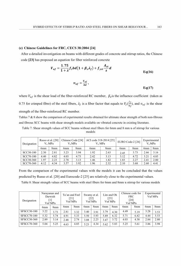
(e) Chinese Guidelines for FRC, CECS 38:2004 [24]
After a detailed investigation on beams with different grades of concrete and stirrup ratios, the Chinese
code [23] has proposed an equation for fiber reinforced concrete
@E5 $ �� �&� � B 541;u� � vDB5w � 5634 C343 ;
Eq(16)
DE5 $ @E51; ,
Eq(17)
where F�c is the shear load of the fiber-reinforced RC member, xyis the influence coefficient (taken as
0.75 for crimped fibre) of the steel fibers, Gc is a fiber factor that equals to Fc�gh�h), and '�c is the shear
strength of the fiber-reinforced RC member. Tables 7 & 8 show the comparison of experimental results obtained for ultimate shear strength of both non-fibrous
and fibrous SCC beams with shear strength models available on vibrated concrete in existing literature.
Table 7: Shear strength values of SCC beams without steel fibers for 6mm and 8 mm � of stirrup for various models
Designation Russo et al. [20]
Vu MPa Chinese Code [24]
Vu MPa ACI code 318-2014 [25]
Vu MPa EURO Code-2 [26] Experimental Vu MPa
6mm 8mm 6mm 8mm 6mm 8mm 6mm 8mm 6mm 8mm SCC30-180 2.30 2.81 3.23 3.94 1.92 2.63 2.45 3.73 2.66 3.16 SCC70-180 4.40 4.82 4.03 4.73 2.42 3.13 3.12 4.72 3.21 4.85 SCC30-360 1.97 2.23 2.78 3.13 1.46 1.82 1.83 2.27 2.41 2.80 SCC70-360 4.12 4.34 3.57 3.92 1.96 2.32 2.10 3.68 2.60 4.41
From the comparison of the experimental values with the models it can be concluded that the values
predicted by Russo et al. [20] and Eurocode-2 [25] are relatively close to the experimental values.
Table 8:�Shear strength values of SCC beams with steel fibers for 6mm and 8mm � stirrup for various models
Designation
Narayanan and Darwish
[1] Vuf MPa
Ta’an and Feel [21]
Vuf MPa
Swamy et al. [22]
Vuf MPa
Lim and Oh [23]
Vuf MPa
Chinese code for FRC [24]
Vuf MPa
Experimental Vuf MPa
6mm 8mm 6mm 8mm 6mm 8mm 6mm 8mm 6mm 8mm 6mm 8mm SFSCC30-180 3.22 3.73 2.81 3.32 3.40 3.91 3.79 4.30 4.49 5.19 3.28 3.53 SFSCC70-180 5.32 5.74 4.91 5.33 5.50 5.93 5.89 6.32 5.71 6.42 4.44 5.53 SFSCC30-360 2.89 3.14 2.48 2.74 3.08 2.23 3.47 3.72 4.03 4.38 2.84 2.80 SFSCC70-360 5.04 5.25 4.63 4.85 5.23 4.34 5.62 5.83 5.25 5.61 3.86 3.98
HYBRID EFFECTS OF STIRRUP RATIO AND STEEL FIBERS ON SHEAR BEHAVIOUR... 163
��
From the above table it can be noted that the values predicted by Narayanan and Darwish [1] are
relatively close to the experimental values.
5. DETAILS OF TESTED BEAMS
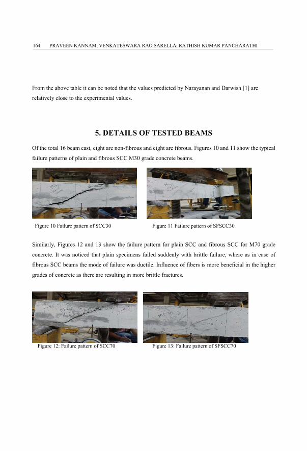
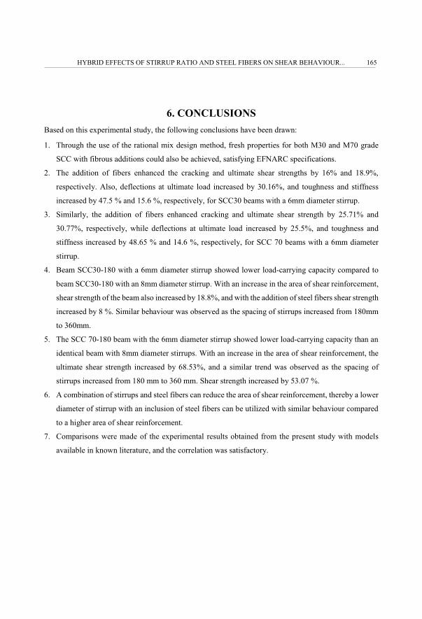
Of the total 16 beam cast, eight are non-fibrous and eight are fibrous. Figures 10 and 11 show the typical
failure patterns of plain and fibrous SCC M30 grade concrete beams.
Figure 10 Failure pattern of SCC30 Figure 11 Failure pattern of SFSCC30
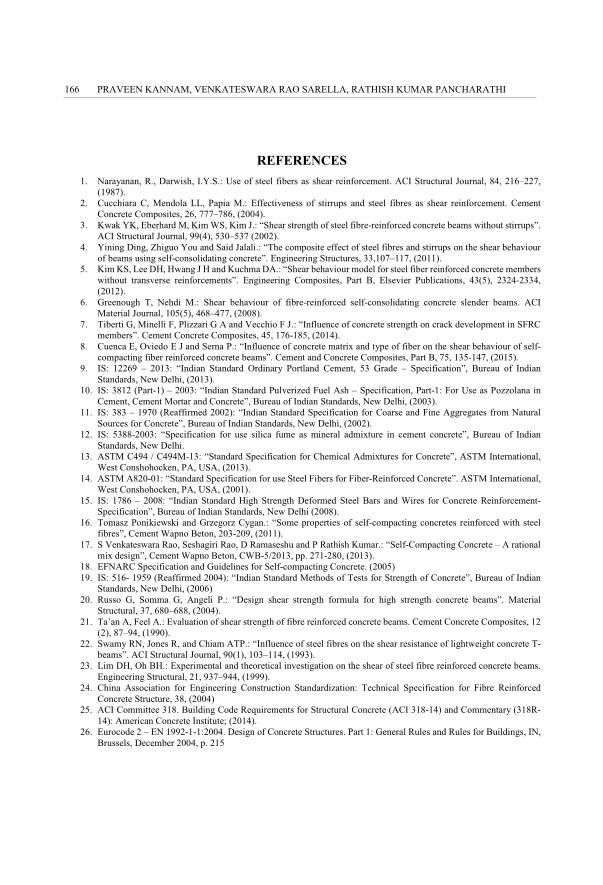
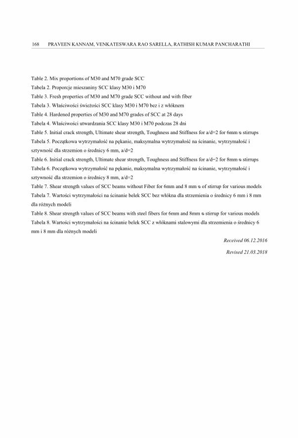
Similarly, Figures 12 and 13 show the failure pattern for plain SCC and fibrous SCC for M70 grade
concrete. It was noticed that plain specimens failed suddenly with brittle failure, where as in case of
fibrous SCC beams the mode of failure was ductile. Influence of fibers is more beneficial in the higher
grades of concrete as there are resulting in more brittle fractures.
Figure 12: Failure pattern of SCC70 Figure 13: Failure pattern of SFSCC70
PRAVEEN KANNAM, VENKATESWARA RAO SARELLA, RATHISH KUMAR PANCHARATHI164
��
6. CONCLUSIONS Based on this experimental study, the following conclusions have been drawn:
1. Through the use of the rational mix design method, fresh properties for both M30 and M70 grade
SCC with fibrous additions could also be achieved, satisfying EFNARC specifications.
2. The addition of fibers enhanced the cracking and ultimate shear strengths by 16% and 18.9%,
respectively. Also, deflections at ultimate load increased by 30.16%, and toughness and stiffness
increased by 47.5 % and 15.6 %, respectively, for SCC30 beams with a 6mm diameter stirrup.
3. Similarly, the addition of fibers enhanced cracking and ultimate shear strength by 25.71% and
30.77%, respectively, while deflections at ultimate load increased by 25.5%, and toughness and
stiffness increased by 48.65 % and 14.6 %, respectively, for SCC 70 beams with a 6mm diameter
stirrup.
4. Beam SCC30-180 with a 6mm diameter stirrup showed lower load-carrying capacity compared to
beam SCC30-180 with an 8mm diameter stirrup. With an increase in the area of shear reinforcement,
shear strength of the beam also increased by 18.8%, and with the addition of steel fibers shear strength
increased by 8 %. Similar behaviour was observed as the spacing of stirrups increased from 180mm
to 360mm.
5. The SCC 70-180 beam with the 6mm diameter stirrup showed lower load-carrying capacity than an
identical beam with 8mm diameter stirrups. With an increase in the area of shear reinforcement, the
ultimate shear strength increased by 68.53%, and a similar trend was observed as the spacing of
stirrups increased from 180 mm to 360 mm. Shear strength increased by 53.07 %.
6. A combination of stirrups and steel fibers can reduce the area of shear reinforcement, thereby a lower
diameter of stirrup with an inclusion of steel fibers can be utilized with similar behaviour compared
to a higher area of shear reinforcement.
7. Comparisons were made of the experimental results obtained from the present study with models
available in known literature, and the correlation was satisfactory.
HYBRID EFFECTS OF STIRRUP RATIO AND STEEL FIBERS ON SHEAR BEHAVIOUR... 165
��
REFERENCES 1. Narayanan, R., Darwish, I.Y.S.: Use of steel fibers as shear reinforcement. ACI Structural Journal, 84, 216–227,
(1987). 2. Cucchiara C, Mendola LL, Papia M.: Effectiveness of stirrups and steel fibres as shear reinforcement. Cement
Concrete Composites, 26, 777–786, (2004). 3. Kwak YK, Eberhard M, Kim WS, Kim J.: “Shear strength of steel fibre-reinforced concrete beams without stirrups”.
ACI Structural Journal, 99(4), 530–537 (2002). 4. Yining Ding, Zhiguo You and Said Jalali.: “The composite effect of steel fibres and stirrups on the shear behaviour
of beams using self-consolidating concrete”. Engineering Structures, 33,107–117, (2011). 5. Kim KS, Lee DH, Hwang J H and Kuchma DA.: “Shear behaviour model for steel fiber reinforced concrete members
without transverse reinforcements”. Engineering Composites, Part B, Elsevier Publications, 43(5), 2324-2334, (2012).
6. Greenough T, Nehdi M.: Shear behaviour of fibre-reinforced self-consolidating concrete slender beams. ACI Material Journal, 105(5), 468–477, (2008).
7. Tiberti G, Minelli F, Plizzari G A and Vecchio F J.: “Influence of concrete strength on crack development in SFRC members”. Cement Concrete Composites, 45, 176-185, (2014).
8. Cuenca E, Oviedo E J and Serna P.: “Influence of concrete matrix and type of fiber on the shear behaviour of self-compacting fiber reinforced concrete beams”. Cement and Concrete Composites, Part B, 75, 135-147, (2015).
9. IS: 12269 – 2013: “Indian Standard Ordinary Portland Cement, 53 Grade – Specification”, Bureau of Indian Standards, New Delhi, (2013).
10. IS: 3812 (Part-1) – 2003: “Indian Standard Pulverized Fuel Ash – Specification, Part-1: For Use as Pozzolana in Cement, Cement Mortar and Concrete”, Bureau of Indian Standards, New Delhi, (2003).
11. IS: 383 – 1970 (Reaffirmed 2002): “Indian Standard Specification for Coarse and Fine Aggregates from Natural Sources for Concrete”, Bureau of Indian Standards, New Delhi, (2002).
12. IS: 5388-2003: “Specification for use silica fume as mineral admixture in cement concrete”, Bureau of Indian Standards, New Delhi.
13. ASTM C494 / C494M-13: “Standard Specification for Chemical Admixtures for Concrete”, ASTM International, West Conshohocken, PA, USA, (2013).
14. ASTM A820-01: “Standard Specification for use Steel Fibers for Fiber-Reinforced Concrete”. ASTM International, West Conshohocken, PA, USA, (2001).
15. IS: 1786 – 2008: “Indian Standard High Strength Deformed Steel Bars and Wires for Concrete Reinforcement- Specification”, Bureau of Indian Standards, New Delhi (2008).
16. Tomasz Ponikiewski and Grzegorz Cygan.: “Some properties of self-compacting concretes reinforced with steel fibres”, Cement Wapno Beton, 203-209, (2011).
17. S Venkateswara Rao, Seshagiri Rao, D Ramaseshu and P Rathish Kumar.: “Self-Compacting Concrete – A rational mix design”, Cement Wapno Beton, CWB-5/2013, pp. 271-280, (2013).
18. EFNARC Specification and Guidelines for Self-compacting Concrete. (2005) 19. IS: 516- 1959 (Reaffirmed 2004): “Indian Standard Methods of Tests for Strength of Concrete”, Bureau of Indian
Standards, New Delhi, (2006) 20. Russo G, Somma G, Angeli P.: “Design shear strength formula for high strength concrete beams”. Material
Structural, 37, 680–688, (2004). 21. Ta’an A, Feel A.: Evaluation of shear strength of fibre reinforced concrete beams. Cement Concrete Composites, 12
(2), 87–94, (1990). 22. Swamy RN, Jones R, and Chiam ATP.: “Influence of steel fibres on the shear resistance of lightweight concrete T-
beams”. ACI Structural Journal, 90(1), 103–114, (1993). 23. Lim DH, Oh BH.: Experimental and theoretical investigation on the shear of steel fibre reinforced concrete beams.
Engineering Structural, 21, 937–944, (1999). 24. China Association for Engineering Construction Standardization: Technical Specification for Fibre Reinforced
Concrete Structure, 38, (2004) 25. ACI Committee 318. Building Code Requirements for Structural Concrete (ACI 318-14) and Commentary (318R-
14): American Concrete Institute; (2014). 26. Eurocode 2 – EN 1992-1-1:2004. Design of Concrete Structures. Part 1: General Rules and Rules for Buildings, IN,
Brussels, December 2004, p. 215
PRAVEEN KANNAM, VENKATESWARA RAO SARELLA, RATHISH KUMAR PANCHARATHI166

��
LIST OF FIGURES AND TABLES:
Figure 1. Details of reinforcement for M30 mix with a/d=2
Rysunek 1. Szczegóły zbrojenia dla mieszaniny M30 z a/d=2
Figure 2. Details of reinforcement for M70 mix with a/d=2
Rysunek 2. Szczegóły zbrojenia dla mieszaniny M70 z a/d=2
Figure 3. some tests on workability of SCC
Rysunek 3. Wybrane badania obrabialno�ci SCC
Figure 4. Shear Strength vs stirrup diameter for 180 mm spacing
Rysunek 4. Wytrzymało�� na �cinanie a �rednica strzemienia dla rozstawu 180 mm
Figure 5. Shear Strength vs stirrup diameter for 360 mm spacing
Rysunek 5. Wytrzymało�� na �cinanie a �rednica strzemienia dla rozstawu 360 mm
Figure 6: Toughness vs. stirrup spacing for 6mm � stirrup
Rysunek 6. Wytrzymało�� a rozstaw dla strzemienia o �rednicy 6mm
Figure 7. Toughness vs stirrup Spacing for 8mm � stirrup
Rysunek 7. Wytrzymało�� a rozstaw dla strzemienia o �rednicy 8mm
Figure 8(a). Load Vs Deflections for SCC 30; 8mm � Stirrup
Rysunek 8(a). Obci��enie a ugicia dla SCC 30; strzemi o �rednicy 8mm
Figure 8(b). Load Vs Deflections for SCC 30; 6mm � Stirrup
Rysunek 8(b). Obci��enie a ugicia dla SCC 30; strzemi o �rednicy 6mm
Figure 9(a). Load Vs Deflections for SCC 70; 8mm � Stirrup
Rysunek 9(a). Obci��enie a ugicia dla SCC 70; strzemi o �rednicy 8mm
Figure 9(b). Load Vs Deflections for SCC 70; 6mm � Stirrup
Rysunek 9(b). Obci��enie a ugicia dla SCC 70; strzemi o �rednicy 6mm
Figure 10. Failure pattern of SCC30
Rysunek 10. Schemat błdu SCC30
Figure 11. Failure pattern of SFSCC30
Rysunek 11. Schemat błdu SFSCC30
Figure 12. Failure pattern of SCC70
Rysunek 12. Schemat błdu SCC70
Figure 13. Failure pattern of SFSCC70
Rysunek 13. Schemat błdu SFSCC70
Table 1. Details of beams
Tabela 1. Szczegółowe informacje na temat belek
HYBRID EFFECTS OF STIRRUP RATIO AND STEEL FIBERS ON SHEAR BEHAVIOUR... 167
��
Table 2. Mix proportions of M30 and M70 grade SCC
Tabela 2. Proporcje mieszaniny SCC klasy M30 i M70
Table 3. Fresh properties of M30 and M70 grade SCC without and with fiber
Tabela 3. Wła�ciwo�ci �wie�o�ci SCC klasy M30 i M70 bez i z włóknem
Table 4. Hardened properties of M30 and M70 grades of SCC at 28 days
Tabela 4. Wła�ciwo�ci utwardzania SCC klasy M30 i M70 podczas 28 dni
Table 5. Initial crack strength, Ultimate shear strength, Toughness and Stiffness for a/d=2 for 6mm � stirrups
Tabela 5. Pocz�tkowa wytrzymało�� na pkanie, maksymalna wytrzymało�� na �cinanie, wytrzymało�� i
sztywno�� dla strzemion o �rednicy 6 mm, a/d=2
Table 6. Initial crack strength, Ultimate shear strength, Toughness and Stiffness for a/d=2 for 8mm � stirrups
Tabela 6. Pocz�tkowa wytrzymało�� na pkanie, maksymalna wytrzymało�� na �cinanie, wytrzymało�� i
sztywno�� dla strzemion o �rednicy 8 mm, a/d=2
Table 7. Shear strength values of SCC beams without Fiber for 6mm and 8 mm � of stirrup for various models
Tabela 7. Warto�ci wytrzymało�ci na �cinanie belek SCC bez włókna dla strzemienia o �rednicy 6 mm i 8 mm
dla ró�nych modeli
Table 8.�Shear strength values of SCC beams with steel fibers for 6mm and 8mm � stirrup for various models
Tabela 8.�Warto�ci wytrzymało�ci na �cinanie belek SCC z włóknami stalowymi dla strzemienia o �rednicy 6
mm i 8 mm dla ró�nych modeli
Received 06.12.2016
Revised 21.03.2018
PRAVEEN KANNAM, VENKATESWARA RAO SARELLA, RATHISH KUMAR PANCHARATHI168
��
HYBRYDOWY WPŁYW STOSUNKU STRZEMION I WŁÓKIEN STALOWYCH NA �CINANIE
BETONU SAMOZAG�SZCZALNEGO
Słowa kluczowe: beton samozagszczalny, �cinanie, beton zbrojony (RC), �cinanie spowodowane zginaniem.
STRESZCZENIE:
Spo�ród wszystkich rodzajów uszkodze betonu, �cinanie jest nagłe i kruche i pojawia si gwałtownie, bez
ostrze�enia. Aby unikn�� tego rodzaju problemów z betonem, belki s� tradycyjnie wzmacniane za pomoc� strzemion, w
bli�szej odległo�ci od konstrukcji. Ograniczone rozmieszczenie prtów zbrojeniowych i strzemion na elementach
wykonanych z betonu zbrojonego (RC), takich jak słupy, belki i płyty, utrudnia zagszczanie betonu w ka�dym miejscu w
szalunku za pomoc� wibratorów mechanicznych. Pustki i makropory wewn�trz betonu powstaj� w wyniku nieodpowiednich
drga, a zatem zagszczenie mo�e wpływa� na wytrzymało�� mechaniczn� i trwało�� betonu, a tak�e sta� si mo�liw�
przyczyn� pogorszenia jego jako�ci.
Beton konwencjonalny stosowany w budownictwie i in�ynierii l�dowej wymaga zagszczania w celu uzyskania
wytrzymało�ci, trwało�ci i konsystencji. Ta klasyczna metoda zagszczania i drga powoduje zakłócenia i dodatkowe koszty
dla projektów, a ponadto stanowi powa�ne zagro�enie dla zdrowia na i w okolicach placu budowy. Beton samozagszczalny
(SCC), jak sama nazwa wskazuje, nie wymaga zewntrznego wysiłku przy zagszczaniu. Jest to dobrze przemy�lane
rozwi�zanie, maj�ce na celu pozbycie si powy�szego problemu. Ze wzgldu na wy�ej opisan� wła�ciwo��, nie potrzeba
drga, a wic nie powstaj� równie� zanieczyszczenia hałasem, zmniejszaj� si koszty robocizny i beton mo�e by� zagszczany
w ka�dym miejscu szalunku, bez jakiejkolwiek znacz�cej segregacji, przewa�nie w zatkanych wzmocnieniach.
W niniejszej pracy przedstawiono charakterystyk pkania przy �cinaniu włóknistego betonu samozagszczalnego
o normalnym i wysokim stopniu wytrzymało�ci (M30 i M70). W niniejszej pracy zastosowano dwie �rednice strzemion (6
mm i 8 mm) o stałej zawarto�ci włókien stalowych wynosz�cej 38 kg/m3 (0.5% objto�ci betonu). Rozmiar belki został
ustalony na 100 x 200 x 1200 mm. Przez cały okres trwania badania utrzymywano wyra�ny rozstaw belek wynosz�cy 1100
mm. Ł�cznie zbadano 16 belek z niedostatnim �cinaniem przy obci��eniu trzypunktowym. Dwa rozstawy strzemion (180 mm
i 360 mm) s� stosowane dla stosunku �cinania do głboko�ci (a/d = 2). Badanie wykazało, �e pocz�tkowe obci��enie przy
pkaniu oraz kocowe obci��enie wzrosły wraz ze wzrostem �rednicy strzemienia. Zauwa�ono równie�, �e tryb awaryjny
zmienił si z kruchego �cinania na �cinanie spowodowane zginaniem przy obecno�ci włókien. Zachowanie mechaniczne
SFRSCC uległo poprawie w wyniku poł�czonego efektu działania strzemion i włókien stalowych. Sztywno��, wytrzymało��
i ugicie belek wzrosły w porównaniu do belek SCC bez włókien. Wyniki eksperymentalne zostały porównane z istniej�cymi
modelami dostpnymi w literaturze, a korelacja okazała si by� zadowalaj�ca.
�
HYBRID EFFECTS OF STIRRUP RATIO AND STEEL FIBERS ON SHEAR BEHAVIOUR... 169