hybrid 2018 owner’s manual and maintenance …
TRANSCRIPT
HYBRID
2018 OWNER’S MANUALAND MAINTENANCE INFORMATION
For your safety, read carefully and keep in this vehicle.

CALIFORNIA PROPOSITION 65 WARNINGWARNING
Operating, servicing and maintaining a passengervehicle or off-highwaymotor vehicle can expose you tochemicals including engine exhaust, carbon monoxide,phthalates, and lead, which are known to the State ofCalifornia to cause cancer and birth defects or otherreproductive harm. To minimize exposure, avoidbreathing exhaust, do not idle the engine except asnecessary, service your vehicle in a well-ventilated areaand wear gloves or wash your hands frequently whenservicing your vehicle. For more information go towww.P65Warnings.ca.gov/passenger-vehicle.
Your INFINITI represents a new way ofthinking about vehicle design. It integratesadvanced engineering and superior crafts-manship with a simple, refined aestheticsensitivity associated with traditional Japa-nese culture.
The result is a different notion of luxury andbeauty. The car itself is important, but so isthe sense of harmony that the vehicle evokesin its driver, and the sense of satisfaction youfeel with the INFINITI — from the way itlooks and drives to the high level of retailerservice.
To ensure that you enjoy your INFINITI tothe fullest, we encourage you to read thisOwner’s Manual immediately. It explains allof the features, controls and performancecharacteristics of your INFINITI; it alsoprovides important instructions and safetyinformation.
A separate Warranty Information Bookletis included in your Owner’s literature port-folio. Always carry it with you when youtake your vehicle to an INFINITI retailer.The Warranty Information Booklet con-tents provide complete information aboutall warranties covering this vehicle, therequirements to keep the warranties ineffect as well as the INFINITI RoadsideAssistance program.
Additionally, a separate Customer Care andLemon Law Information Booklet will ex-plain how to resolve any concerns you mayhave with your vehicle, as well as clarifyyour rights under your state’s lemon law.
In addition to factory installed options, yourvehicle may also be equipped with additionalaccessories installed by INFINITI or by yourINFINITI retailer prior to delivery. It isimportant that you familiarize yourself withall disclosures, warnings, cautions and in-structions concerning proper use of suchaccessories prior to operating the vehicleand/or accessory. It is recommended yousee an INFINITI retailer for details concern-ing the particular accessories with whichyour vehicle is equipped.
READ FIRST — THEN DRIVESAFELYBefore driving your vehicle, read your Own-er’s Manual carefully. This will ensure famil-iarity with controls and maintenancerequirements, assisting you in the safeoperation of your vehicle.
WARNING
IMPORTANT SAFETY INFORMATIONREMINDERS!
Follow these important driving rules tohelp ensure a safe and comfortable tripfor you and your passengers!
. NEVER drive under the influence ofalcohol or drugs.
. ALWAYS observe posted speed lim-its and never drive too fast forconditions.
. ALWAYS give your full attention todriving and avoid using vehicle fea-tures or taking other actions thatcould distract you.
. ALWAYS use your seat belts andappropriate child restraint systems.Pre-teen children should be seated inthe rear seat.
Foreword

. ALWAYS provide information aboutthe proper use of vehicle safetyfeatures to all occupants of thevehicle.
. ALWAYS review this Owner’s Man-ual for important safety information.
MODIFICATION OF YOUR VEHI-CLEThis vehicle should not be modified. Mod-ification could affect its performance,safety or durability, and may even violategovernmental regulations. In addition, da-mage or performance problems resultingfrom modification will not be coveredunder the INFINITI warranties.
WARNING
Installing an aftermarket On-Board Di-agnostic (OBD) plug-in device that usesthe port during normal driving, forexample remote insurance companymonitoring, remote vehicle diagnostics,telematics or engine reprogramming,may cause interference or damage tovehicle systems. We do not recommendor endorse the use of any aftermarket
OBD plug-in devices, unless specificallyapproved by INFINITI. The vehicle war-ranty may not cover damage caused byany aftermarket plug-in device.
WHEN READING THE MANUALThis manual includes information for allfeatures and equipment available on thismodel. Features and equipment in yourvehicle may vary depending on model, trimlevel, options selected, order, date of pro-duction, region or availability. Therefore,you may find information about features orequipment that are not included or installedon your vehicle.
All information, specifications and illustra-tions in this manual are those in effect at thetime of printing. INFINITI reserves the rightto change specifications, performance, de-sign or component suppliers without noticeand without obligation. From time to time,INFINITI may update or revise this manual toprovide owners with the most accurateinformation currently available. Please care-fully read and retain with this manual allrevision updates sent to you by INFINITI toensure you have access to accurate and up-to-date information regarding your vehicle.Current versions of vehicle Owner’sManualsand any updates can also be found in theowner section of the INFINITI website at
https://owners.infinitiusa.com/owners/na-vigation/manualsandGuides. If you havequestions concerning any information inyour Owner’s Manual, contact INFINITIConsumer Affairs. See the INFINITI CUS-TOMER CARE PROGRAM page in thisOwner’s Manual for contact information.
IMPORTANT INFORMATIONABOUT THIS MANUALYou will see various symbols in this manual.They are used in the following ways:
WARNING
This is used to indicate the presence of ahazard that could cause death or seriouspersonal injury. To avoid or reduce therisk, the procedures must be followedprecisely.
CAUTION
This is used to indicate the presence of ahazard that could cause minor or mod-erate personal injury or damage to yourvehicle. To avoid or reduce the risk, theprocedures must be followed carefully.
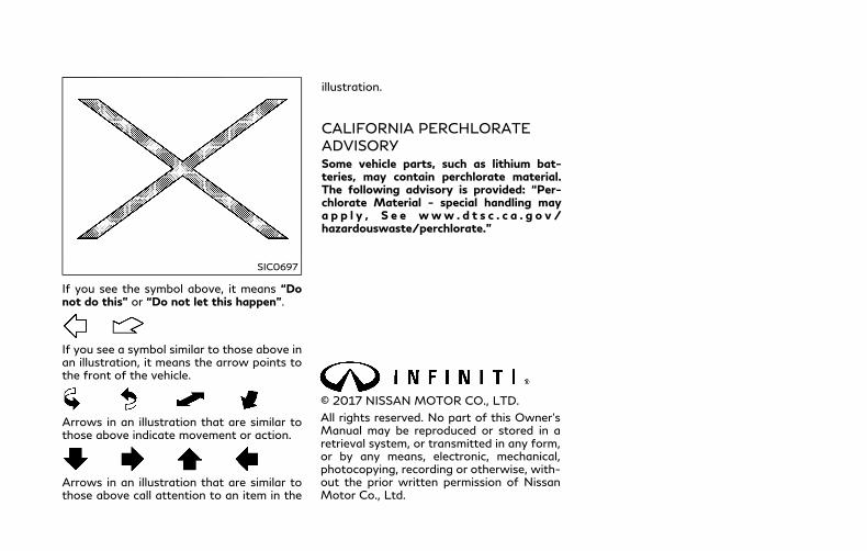
SIC0697
If you see the symbol above, it means “Donot do this” or “Do not let this happen”.
If you see a symbol similar to those above inan illustration, it means the arrow points tothe front of the vehicle.
Arrows in an illustration that are similar tothose above indicate movement or action.
Arrows in an illustration that are similar tothose above call attention to an item in the
illustration.
CALIFORNIA PERCHLORATEADVISORYSome vehicle parts, such as lithium bat-teries, may contain perchlorate material.The following advisory is provided: “Per-chlorate Material - special handling maya p p l y , S e e www . d t s c . c a . g o v /hazardouswaste/perchlorate.”
© 2017 NISSAN MOTOR CO., LTD.
All rights reserved. No part of this Owner’sManual may be reproduced or stored in aretrieval system, or transmitted in any form,or by any means, electronic, mechanical,photocopying, recording or otherwise, with-out the prior written permission of NissanMotor Co., Ltd.
INFINITI CUSTOMER CARE PROGRAMINFINITI CARES ...
Both INFINITI and your INFINITI retailer are dedicated to serving all your automotive needs. Your satisfaction with your vehicle and yourINFINITI retailer are our primary concerns. Your INFINITI retailer is always available to assist you with all your automobile sales and serviceneeds.
However, if there is something that yourINFINITI retailer cannot assist you with oryou would like to provide INFINITI directlywith comments or questions, please contactour (INFINITI’s) Consumer Affairs Depart-ment using our toll-free number:
For U.S. customers1-800-662-6200
For Canadian customers1-800-361-4792
The Consumer Affairs Department will askfor the following information:
. Your name, address, and telephone num-ber
. Vehicle identification number (on dashpanel)
. Date of purchase
. Current odometer reading
. Your INFINITI retailer’s name
. Your comments or questions
OR
You can write to INFINITI with the informa-tion on the left at:
For U.S. customersINFINITI DivisionNissan North America, Inc.Consumer Affairs DepartmentP.O. Box 685003Franklin, TN 37068-5003or via e-mail at:[email protected]
For Canadian customersINFINITI DivisionNissan Canada Inc.5290 Orbitor DriveMississauga, Ontario L4W 4Z5or via e-mail at:[email protected]
If you prefer, visit us at:
www.infinitiUSA.com (for U.S. customer) or
www.infiniti.ca (for Canadian customers)
We appreciate your interest in INFINITI andthank you for buying a quality INFINITIvehicle.
Hybrid System OverviewHybridSystem
Illustrated table of contents 0
Safety — Seats, seat belts and supplemental restraint system
Instruments and controls
Pre-driving checks and adjustments
Monitor, climate, audio, phone and voice recognition systems
Starting and driving
In case of emergency
Appearance and care
Do-it-yourself
Maintenance and schedules
1
2
3
4
5
6
7
8
9
Table ofContents
10Technical and consumer information
11Index

Hybrid System Overview
INFINITI Direct ResponseHybrid® System......................................... Hybrid System-2
Lithium-ion (Li-ion) battery................... Hybrid System-2
High voltage cautions ............................. Hybrid System-2
Road accident cautions .......................... Hybrid System-3
Emergency shut-off system .................. Hybrid System-4
Operation of the INFINITI DirectResponse Hybrid® System ..................... Hybrid System-4
Starting and slow speed driving ..... Hybrid System-5
Medium or high speed driving......... Hybrid System-5
Rapid acceleration .............................. Hybrid System-5
Deceleration and braking.................. Hybrid System-5
Stopping ................................................ Hybrid System-5
Energy monitors....................................... Hybrid System-5
Assist charge gauge ......................... Hybrid System-6
Energy Flow ....................................... Hybrid System-6
Fuel economy history ...................... Hybrid System-7
Regenerative brake ................................. Hybrid System-8
Efficient use of your vehicle ................. Hybrid System-8
Approaching Vehicle Sound forPedestrians (VSP) system ..................... Hybrid System-9
Hybrid vehicle precautions ................. Hybrid System-10
High voltage components ........... Hybrid System-10
Hybrid vehicle characteristics...... Hybrid System-11
Hybrid System-2 Hybrid System Overview
The INFINITI Direct Response Hybrid® Sys-tem combines the power of a gasolineengine and an electric motor to help mini-mize fuel consumption and emissions.
Depending on driving conditions, the vehicleruns on a combination of the gasoline engineand the electric motor, whichever is best forthose conditions.
Because the gasoline engine charges theLithium-ion (Li-ion) battery as needed, thebattery does not have to be charged from anoutside source like an all-electric vehicle.
WARNING
Your vehicle contains a sealed Lithiumion (Li-ion) high voltage battery. If theLi-ion battery is disposed of improperly,there is a risk of severe burns andelectrical shock that may result in ser-ious injury or death and there is also arisk of environmental damage.
CAUTION
. Do not misuse the Li-ion battery.
. Do not use the Li-ion battery for anyother purpose.
The Li-ion battery is used to drive theelectric motors in the INFINITI Direct Re-sponse Hybrid® System.
The Li-ion battery has a limited service life. Itis recommended that you contact yourINFINITI retailer for information about re-cycling or disposal of the battery.
WARNING
. The INFINITI Direct Response Hy-brid® System uses high voltage up toapproximately 408 volts. The systemcan be hot during and after starting.Be careful of both the high voltageand the high temperature. Obey thewarning labels attached to the vehi-cle.
. Never disassemble, remove or replacehigh-voltage parts and harnesses aswell as their connectors. Doing so cancause severe burns or electric shockthat may result in serious injury ordeath. High-voltage harnesses arecolored orange. The vehicle highvoltage system has no user service-able parts. It is recommended thatyou take your vehicle to an INFINITIretailer for any necessary mainte-nance.
. Never try to remove the service pluglocated in the trunk. The service plugis used only when the vehicle isserviced by trained technicians wear-ing personal protection equipmentand is part of the high voltagesystem. Touching the service plugcan cause severe burns or electricshock that may result in serious injury
INFINITI DIRECT RESPONSEHYBRID® SYSTEM LITHIUM-ION (Li-ion) BATTERY HIGH VOLTAGE CAUTIONS

or death.WARNING
In case of a collision:
. If your vehicle is drivable, pull yourvehicle off the road, put the trans-mission in the P (Park) position, applythe parking brake and turn theINFINITI Direct Response Hybrid®
System off.
. Check to see if there are exposed highvoltage parts and cables. Never touchthe parts and cables. For their loca-tions, see “High voltage components”(P.Hybrid System-10). To avoid per-sonal injury, never touch high-vol-tage wiring, connectors, and otherhigh-voltage parts, such as electricmotor inverter and Lithium ion (Li-ion) battery. An electric shock mayoccur if exposed electric wires arevisible when viewed from inside oroutside of your vehicle. Therefore,never touch exposed electric wires.
. If the vehicle receives a strong impactto the floor while driving, stop thevehicle in a safe location and checkthe floor.
. Inspect the ground under the vehicle.If liquid has leaked onto the ground,the fuel system may have been da-
maged. Leave the vehicle as soon aspossible.
. Leaks or damage to the Li-ion bat-tery may result in a fire. If youdiscover them, contact emergencyservices immediately. Since the fluidleak may be lithium organic electro-lyte from the Li-ion battery, nevertouch the fluid leak inside or outsidethe vehicle. If the fluid contacts yourskin or eyes, wash it off immediatelywith a large amount of water andreceive immediate medical attentionto help avoid serious injury.
. If a fire occurs in the hybrid vehicle,leave the vehicle as soon as possible.Only use a type ABC, BC or C fireextinguisher that is meant for use onelectrical fires. Using water or theincorrect fire extinguisher can resultin serious injury or death from elec-trical shock.
. If you are not able to safely assessthe vehicle due to vehicle damage, donot touch the vehicle. Leave thevehicle and contact emergency ser-vices. Advise 1st responders that thisis a hybrid vehicle.
. In the event of an accident thatrequires body repair and painting, itis recommended that the vehicle be
Hybrid System Overview Hybrid System-3
ROAD ACCIDENT CAUTIONS
Hybrid System-4 Hybrid System Overview
delivered to an INFINITI retailer tohave the Li-ion battery pack and highvoltage parts such as the inverter,including the wiring harness, re-moved prior to painting. Li-ion bat-tery packs exposed to heat in thepaint booth will experience capacityloss. Damaged Li-ion battery packsmay also pose safety risks to un-trained mechanics and repair person-nel.
The emergency shut-off system is activatedand the high-voltage system automaticallyturns off in the following conditions:
. Front and side collisions in which the airbags are deployed.
. Certain rear collisions.
. Certain INFINITI Direct Response Hy-brid® System malfunctions
For the above collisions and the certainhybrid system malfunctions, the READY todrive indicator light will turn off. See “Warn-ing lights, indicator lights and audible re-minders” (P.2-9).
The emergency shut-off activates for theabove collisions to minimize risk of an eventthat could cause injury or an accident. If theemergency shut-off system activates, thehybrid system may not switch to READY todrive position. If this occurs, it is recom-mended that you contact an INFINITI re-tailer. Even if the ignition switch is switchedto READY to drive position, the system mayshut-off suddenly. Therefore, drive cau-tiously to the nearest INFINITI retailer orcontact an INFINITI retailer as soon aspossible.
To start the INFINITI Direct ResponseHybrid® System:
1. Depress the brake pedal and place theignition switch in the ON position whenthe transmission is in the P (Park) or N(Neutral) position (P is recommended).(For more details, see “Push-buttonignition switch” (P.5-11).)
2. The READY to drive indicator lightflashes, then turns illuminated. (Thehybrid system switched to the READYto drive mode when the indicator lightilluminates.)
When the READY to drive indicator lightilluminates, the vehicle can be driven,
even if the gasoline engine is not running.
NOTE:
The gasoline engine starts and stops auto-matically. It may stop during low speeddriving, deceleration or when the vehicle isstopped.
The gasoline engine may automatically runin the following conditions:. The level of remaining charge in the
Lithium ion (Li-ion) battery is low. Theengine runs to charge the Li-ion batteryand to provide power to the drive thevehicle.
. The temperature of the engine coolant islow.
EMERGENCY SHUT-OFF SYSTEM OPERATIONOFTHE INFINITI DIRECTRESPONSE HYBRID® SYSTEM

. Based on driving conditions.
. The shift lever is shifted to the P (Park)position, the driver’s seat belt is re-leased and the driver’s side door is thenopened.
The hybrid system operates as follows basedon driving conditions and the Li-ion batterycharge.
STARTING AND SLOW SPEEDDRIVINGThe vehicle is driven by the electric motordepending on the available Li-ion batterycharge.
MEDIUM OR HIGH SPEED DRIV-INGThe system automatically controls the gaso-line engine and electric motor in order toobtain the optimum fuel mileage and per-formance, depending on the driving situationand available Li-ion battery charge.
When the remaining battery level is low, theLi-ion battery is charged by the electricmotor that is driven to generate electricpower while the vehicle is driving.
RAPID ACCELERATIONThe vehicle is accelerated using both thegasoline engine and the electric motordepending on the available Li-ion batterycharge.
DECELERATION AND BRAKINGThe Li-ion battery is charged by the electricmotor that changes the energy of therotating wheels into electric power. See“Regenerative brake” (P.Hybrid System-8).
STOPPINGThe gasoline engine may stop running tosave fuel depending on the available Li-ionbattery charge.
The INFINITI Direct Response Hybrid® Sys-tem monitors the status of power being sentto the electric motor and the Lithium ion (Li-ion) battery state of charge. The status isshown on the assist charge gauge in themeter and the energy flow/remaining Li-ionbattery charge in the lower display and themeter. System status can also be shownwhen the screen is in the energy flow modeor energy/fuel history mode.
Hybrid System Overview Hybrid System-5
ENERGY MONITORS

Hybrid System-6 Hybrid System Overview
JVO0109X
ASSIST CHARGE GAUGEThis gauge indicates the actual electricmotor power consumption and the chargingpower to the Li-ion battery.
For additional information, see “Assistcharge gauge” (P.2-7).
ENERGY FLOWWhen you use this system, make sure thehybrid system is in the READY to drivemode.See “Operation of the INFINITI DirectResponse Hybrid® System” (P.Hybrid Sys-tem-4).
JVO0111X
All-Wheel Drive (AWD) modelsIf you use the system with the hybridsystem off (ignition switch placed in theACC position) for a long time, it willdischarge the 12-volt battery power, andthe hybrid system will not start.
Energy monitor for various operating modescan be displayed in the lower display.
The energy flow is also displayed in thevehicle information display. (See “1. Energymonitor” (P.2-27).)
This is an example of the Energy Flowdisplay. The Energy Flow display changes,depending on the following operating con-ditions. The graphic indicates the amount ofpower in the Li-ion battery.
The following are displayed on the EnergyFlow screen.
. When the vehicle is powered only by theelectric motor.
. When the vehicle is powered only by thegasoline engine.
. When the vehicle is powered by both theelectric motor and the gasoline engine.
. When the vehicle is charging the Li-ionbattery with the regenerative brake andgasoline engine.
. When the vehicle is charging the Li-ionbattery with the regenerative brake.
. When the vehicle is charging the Li-ionbattery with the gasoline engine.
. When the vehicle is powered by thegasoline engine and is charging the Li-ion battery.
. When there is no Energy Flow in thevehicle
. When the vehicle is driving by the All-Wheel Drive (AWD) (AWD models).

FUEL ECONOMY HISTORYThe Fuel Economy History screen appears inthe lower display when the screen is in theFuel Economy History mode.
JVS0246X
1. Push the MENU button and touch[Information].
2. Touch [Fuel Economy History].
JVO0112X
The Fuel Economy History displays thevehicle’s average fuel consumption and re-generative electric power at 2 minute inter-vals.
The displayed values on the screen indicategeneral driving conditions. Accuracy varieswith driving habits and road conditions.
1. Regenerated energy in the past 12minutes: The regenerated energy in thepast 12 minutes is indicated with sym-bols . One symbol indicates 30 watt-hour. The energy of 30 watt-hour illu-minates a 30 watt bulb for an hour.
2. Fuel consumption (without latest col-umn) in the past 12 minutes: Fuel con-sumption in the past 12 minutes is
Hybrid System Overview Hybrid System-7

Hybrid System-8 Hybrid System Overview
displayed.
3. Current fuel consumption (Latest col-umn): The current fuel consumption iscalculated and displayed based on dis-tance and fuel consumption.
NOTE:
The fuel consumption displays on the upperside of the fuel economy history display,and the regenerated energy displays on thelower side of the economy history.
When the vehicle decelerates while thevehicle is driven with the shift lever in the D(Drive) position or in the manual shift mode,the Lithium ion (Li-ion) battery can becharged by the electric motor. The electricmotor converts the energy of the rotatingwheels into electric power under the follow-ing circumstances:
. When the accelerator pedal is released.
. When the brake pedal is depressed.
. When there is nomalfunction in the brakesystem or the INFINITI Direct ResponseHybrid® System.
The regenerative brake may not work prop-erly if the vehicle has tires and road wheelsother than the ones specified in this manual.
Drive your vehicle with smooth accelerationand deceleration.
. While driving, energy is recoveredthrough the regenerative brake as thevehicle decelerates. However, for mostefficient use, do not accelerate or de-celerate your vehicle more than neces-sary.
. Avoid abrupt acceleration and decelera-tion.
. The power of the Lithium ion (Li-ion)battery can be checked on the EnergyFlow or Energy monitor. See “EnergyFlow” (P.Hybrid System-6) or “Trip com-puter” (P.2-27). Gradual or non-abruptacceleration and deceleration will makemore effective use of the electric power,using less gasoline engine power.
. When parking, be sure to place the shiftlever in the P (Park) position. Whiledriving, place the shift lever in the D(Drive) position.
REGENERATIVE BRAKE EFFICIENT USE OF YOUR VEHICLE
The Approaching Vehicle Sound for Pedes-trians (VSP) system is a function that usessound to help alert pedestrians of thepresence of the vehicle when it is beingdriven at a low speed in the electric drivemode under the following conditions:
. The sound starts when the vehicle startsaccelerating.
. The sound stops when the vehicle speedis more than 19 MPH (30 km/h) whileaccelerating.
. The sound starts when the vehicle speedis less than 16 MPH (25 km/h) whiledecelerating.
. The sound stops when the vehicle stops.
. The sound does not stop with the vehiclein the R (Reverse) position even if thevehicle stops.
The VSP system is automatically turned onwhen the vehicle is in the READY to drivemode.
If there is a malfunction in the VSP system,the VSP OFF indicator light in the meterilluminates. See “Approaching Vehicle Soundfor Pedestrians (VSP) OFF indicator light”(P.2-15).
WARNING
. If the sound from the VSP system isnot heard while driving, stop thevehicle in a safe and quiet location.Open a window, and then place thevehicle in the R (Reverse) positionwith the brake pedal firmly de-pressed. Check that the operatingsound can be heard from the frontside of the vehicle.
. If the sound cannot be heard, havethe system immediately inspected. Itis recommended you visit an INFINITIretailer for this service.
Hybrid System Overview Hybrid System-9
APPROACHING VEHICLE SOUNDFOR PEDESTRIANS (VSP) SYSTEM
Hybrid System-10 Hybrid System Overview
HIGH VOLTAGE COMPONENTS
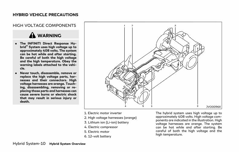
WARNING
. The INFINITI Direct Response Hy-brid® System uses high voltage up toapproximately 408 volts. The systemcan be hot while and after starting.Be careful of both the high voltageand the high temperature. Obey thewarning labels attached to the vehi-cle.
. Never touch, disassemble, remove orreplace the high voltage parts, har-nesses and their connectors. Highvoltage harnesses are orange. Touch-ing, disassembling, removing or re-placing those parts and harnesses cancause severe burns or electric shockthat may result in serious injury ordeath.
JVO0096X
1. Electric motor inverter
2. High voltage harnesses (orange)
3. Lithium ion (Li-ion) battery
4. Electric compressor
5. Electric motor
6. 12-volt battery
The hybrid system uses high voltage up toapproximately 408 volts. High voltage com-ponents are indicated in the illustration. Highvoltage harnesses are orange. The systemcan be hot while and after starting. Becareful of both the high voltage and thehigh temperature.
HYBRID VEHICLE PRECAUTIONS

HYBRID VEHICLE CHARACTER-ISTICS
WARNING
. When you leave your vehicle, be sureto place the ignition switch in theOFF position.
. Be sure to put the transmission in theP (Park) position because the vehiclecan move when the READY to driveindicator light is on even if the gaso-line engine is not running. When theREADY to drive indicator light is on,do not leave your vehicle in a shiftposition other than the P (Park)position. The vehicle will creep andstart abruptly if the accelerator pedalis depressed by mistake. This maycause serious injury or death.
CAUTION
If the vehicle is parked for a long periodof time, the battery discharges gradu-ally. To avoid this occurrence, drive thevehicle for approximately 30 minutes atleast once every two to three months.Otherwise, the Lithium ion (Li-ion) bat-
tery may be damaged. If the Li-ionbattery is completely discharged andthe hybrid system cannot be activated,it is recommended that you contact anINFINITI retailer.
High voltage parts and harnesses on thehybrid vehicles emit approximately the sameamount of electromagnetic waves as theconventional gasoline-powered vehicles orhome electronic appliances despite of theirelectromagnetic shieldings. Unwanted noisemay occur in the reception of a mobile two-way radio.
Charging the Li-ion battery while driving isimportant. The vehicle cannot run if the Li-ion battery is discharged. When in the N(Neutral), D (Drive) or R (Reverse) position,and while the accelerator pedal or the brakepedal is not depressed, the Li-ion batterydoes not recharge. Leaving the transmissionin the N (Neutral), D (Drive) or R (Reverse)position, and while the accelerator pedal orthe brake pedal is not depressed for anextended period of time (for example, whenthe shift lever is in the D (Drive) position andthe vehicle is stopped only by the parkingbrake), may discharge the Li-ion battery andthe hybrid system may automatically beturned off.
JVO0114X
An air vent is located on the right and leftsides between the rear seat and rear door tocool the Li-ion battery and DC/DC conver-ter. If the vent is covered, the Li-ion batteryor DC/DC converter will overheat resultingin reduced output performance of the hybridsystem. See “Lithium-ion (Li-ion) batteryand DC/DC converter air vent” (P.7-5).
Hybrid System Overview Hybrid System-11
Hybrid System-12 Hybrid System Overview
JVO0101X
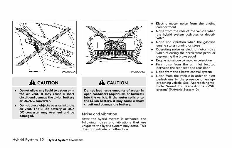
CAUTION
. Do not allow any liquid to get on or inthe air vent. It may cause a shortcircuit and damage the Li-ion batteryor DC/DC converter.
. Do not place objects over or into theair vent. The Li-ion battery or DC/DC converter may overheat and bedamaged.
JVO0006X
CAUTION
Do not load large amounts of water inopen containers (aquariums or buckets)into the vehicle. If the water spills ontothe Li-ion battery, it may cause a shortcircuit and damage the battery.
Noise and vibrationAfter the hybrid system is activated, thefollowing noises and vibrations that areunique to the hybrid system may occur. Thisdoes not indicate a malfunction.
. Electric motor noise from the enginecompartment
. Noise from the rear of the vehicle whenthe hybrid system activates or deacti-vates
. Noise and vibration when the gasolineengine starts running or stops
. Operating noise or electric motor noisewhen releasing the accelerator pedal ordepressing the brake pedal
. Engine noise due to rapid acceleration
. Fan noise from the air inlet locatedbetween the rear seat and rear door
. Noise from the climate control system
. Noise from the vehicle in order to alertpedestrians to the presence of an ap-proaching vehicle. See “Approaching Ve-hicle Sound for Pedestrians (VSP)system” (P.Hybrid System-9).
0 Illustrated table of contents
Seats, seat belts and Supplemental RestraintSystem (SRS) ...................................................................... 0-2
Exterior front ...................................................................... 0-3
Exterior rear ........................................................................ 0-4
Passenger compartment ................................................. 0-5
Cockpit ................................................................................. 0-6
Instrument panel ............................................................... 0-7
Meters and gauges .......................................................... 0-8
Engine compartment ....................................................... 0-9
VQ35HR engine ......................................................... 0-9
Warning and indicator lights ...................................... 0-10
0-2 Illustrated table of contents
JVC1100X
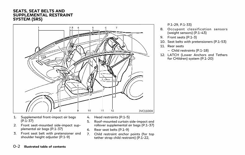
1. Supplemental front-impact air bags(P.1-37)
2. Front seat-mounted side-impact sup-plemental air bags (P.1-37)
3. Front seat belt with pretensioner andshoulder height adjuster (P.1-9)
4. Head restraints (P.1-5)
5. Roof-mounted curtain side-impact androllover supplemental air bags (P.1-37)
6. Rear seat belts (P.1-9)
7. Child restraint anchor points (for toptether strap child restraint) (P.1-22,
P.1-29, P.1-33)
8. Occupant classif ication sensors(weight sensors) (P.1-43)
9. Front seats (P.1-3)
10. Seat belts with pretensioners (P.1-53)
11. Rear seats
— Child restraints (P.1-18)
12. LATCH (Lower Anchors and Tethersfor CHildren) system (P.1-20)
SEATS, SEAT BELTS ANDSUPPLEMENTAL RESTRAINTSYSTEM (SRS)

JVC1103X
1. Hood (P.3-21)
2. Windshield wiper and washer
— Operation (P.2-34)
— Maintenance (P.8-17)
3. Headlight
— Operation (P.2-36)
— Maintenance (P.8-25)
— Adaptive Front lighting System(AFS) (if so equipped) (P.2-41)
4. Moonroof (P.2-54)
5. Power windows (P.2-52)
6. Outside mirrors (P.3-29)
— Side turn signal lights (P.2-42)
— Side view camera*
7. Sonar system*
8. Front view camera*
9. Turn signal (P.2-42, P.8-25)
10. Fog light (P.2-43, P.8-25)
11. Tires
— Wheels and tires (P.8-28, P.10-9)
— Flat tire (P.6-3)
— Tire Pressure Monitoring System(TPMS) (P.2-12, P.5-5)
12. Doors
— Keys (P.3-2)
— Door locks (P.3-4)
— Intelligent Key system (P.3-6)
— Remote keyless entry system(P.3-15)
— Courtesy light (P.2-59)
— Remote engine start (P.3-19)
*: Refer to the Infiniti InTouch Owner’sManual.
Illustrated table of contents 0-3
EXTERIOR FRONT

0-4 Illustrated table of contents
JVC1104X
1. Trunk
— Intelligent Key system (P.3-6)
— Remote keyless entry system(P.3-15)
— Trunk lid (P.3-22)
2. High-mounted stop light (P.8-24)
3. Satellite antenna (P.4-3)
4. Rear window defroster (P.2-36)/An-tenna (P.4-3)
5. Sonar system*
— Back-up Collision Intervention (BCI)system (P.5-59)
6. Rear view camera*
7. Rear combination light (P.8-24)
8. Fuel-filler door
— Operation (P.3-24)
— Fuel information (P.10-4)
9. Child safety rear door locks (P.3-6)
*: Refer to the Infiniti InTouch Owner’sManual.
EXTERIOR REAR

JVC0518X
1. Coat hooks (P.2-51)
2. Rear personal light (P.2-57)
3. Sun visors (P.3-27)
4. Map light (P.2-56)
— SOS call switch*
5. Moonroof switch (P.2-54)
6. Sunglasses holder (P.2-49)
7. Power window switch (P.2-52)/Out-side mirror remote control switch(P.3-29)
8. Automatic drive positioner switch(P.3-30)
9. Inside mirror
— Operation (P.3-28)
— HomeLink® universal transceiver(P.2-59)
10. Rear armrest (P.1-4)
11. Rear cup holders (P.2-47)
12. Rear ashtray (P.2-47)
13. Console box (P.2-50)
— Power outlet (P.2-46)
— Media hub*
14. Front cup holders (P.2-47)
15. Front passenger air bag status light(P.1-45)
*: Refer to the Infiniti InTouch Owner’sManual.
Illustrated table of contents 0-5
PASSENGER COMPARTMENT

0-6 Illustrated table of contents
JVC1106X
1. Side ventilator (P.4-2)
2. Headlight, fog light and turn signalswitch (P.2-36)
3. Steering wheel
— Horn (P.2-43)
— Driver supplemental air bag (P.1-37)
— Heated steering wheel (P.2-45)
— Power steering (P.5-126)
4. Windshield wiper and washer switch(P.2-34)
5. Hazard warning flasher switch (P.6-2)
6. Shift lever (P.5-15)
7. INFINITI controller*
8. Vehicle Dynamic Control (VDC) OFFswitch (P.2-43, P.5-130)
9. Trunk lid release switch (P.3-22)
10. Instrument brightness control switch(P.2-42)
11. TRIP/RESET switch for twin trip od-ometer (P.2-6)
12. Electric tilting/telescopic steeringwheel switch (P.3-27)
13. Steering-wheel-mounted controls (leftside)
— Audio control steering switch*
— Hands-Free Phone System switch*
— Voice recognition system switch*
14. Steering-wheel-mounted controls(right side)
— Trip computer switches (P.2-27)
— Cruise control switches (if soequipped) (P.5-70)
— Intelligent Cruise Control (ICC)switches (if so equipped) (P.5-72)
— Dynamic driver assistance switch (ifso equipped) (P.5-24, P.5-32, P.5-47,P.5-93)
15. INFINITI Drive Mode Selector (P.5-21)
*: Refer to the Infiniti InTouch Owner’sManual.
COCKPIT
JVC1101X
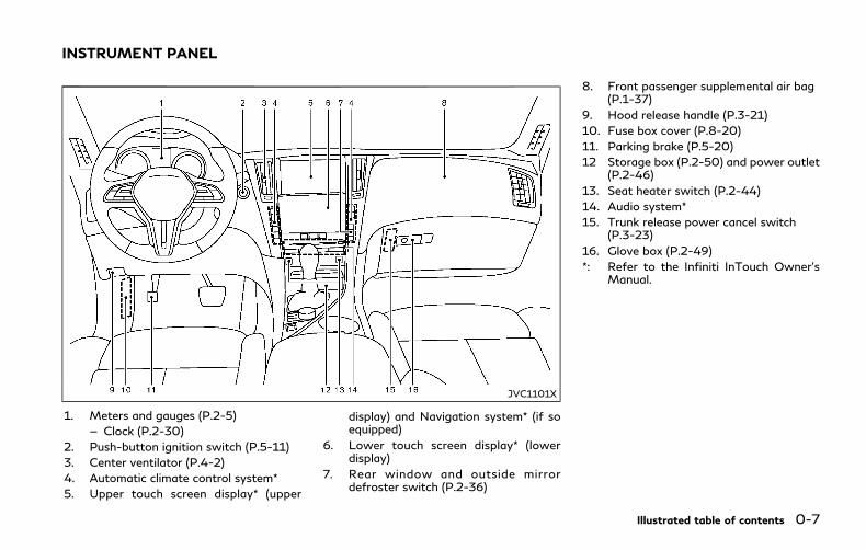
1. Meters and gauges (P.2-5)
— Clock (P.2-30)
2. Push-button ignition switch (P.5-11)
3. Center ventilator (P.4-2)
4. Automatic climate control system*
5. Upper touch screen display* (upper
display) and Navigation system* (if soequipped)
6. Lower touch screen display* (lowerdisplay)
7. Rear window and outside mirrordefroster switch (P.2-36)
8. Front passenger supplemental air bag(P.1-37)
9. Hood release handle (P.3-21)
10. Fuse box cover (P.8-20)
11. Parking brake (P.5-20)
12 Storage box (P.2-50) and power outlet(P.2-46)
13. Seat heater switch (P.2-44)
14. Audio system*
15. Trunk release power cancel switch(P.3-23)
16. Glove box (P.2-49)
*: Refer to the Infiniti InTouch Owner’sManual.
Illustrated table of contents 0-7
INSTRUMENT PANEL
0-8 Illustrated table of contents
JVC0473X
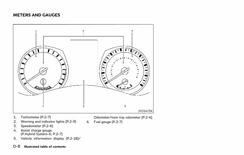
1. Tachometer (P.2-7)
2. Warning and indicator lights (P.2-9)
3. Speedometer (P.2-6)
4. Assist charge gauge(P.Hybrid System-6, P.2-7)
5. Vehicle information display (P.2-18)/
Odometer/twin trip odometer (P.2-6)
6. Fuel gauge (P.2-7)
METERS AND GAUGES
JVM0294X
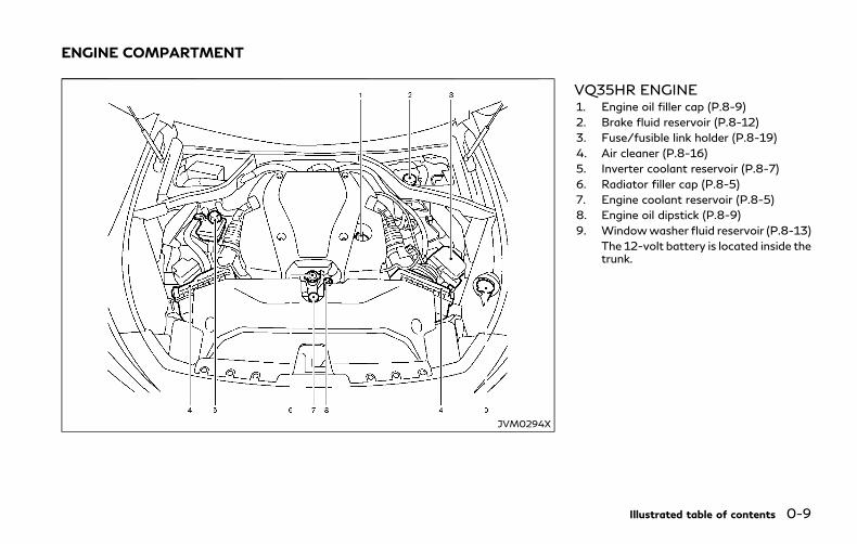
VQ35HR ENGINE1. Engine oil filler cap (P.8-9)
2. Brake fluid reservoir (P.8-12)
3. Fuse/fusible link holder (P.8-19)
4. Air cleaner (P.8-16)
5. Inverter coolant reservoir (P.8-7)
6. Radiator filler cap (P.8-5)
7. Engine coolant reservoir (P.8-5)
8. Engine oil dipstick (P.8-9)
9. Windowwasher fluid reservoir (P.8-13)
The 12-volt battery is located inside thetrunk.
Illustrated table of contents 0-9
ENGINE COMPARTMENT

0-10 Illustrated table of contents
Warninglight
Name Page
12-volt battery chargewarning light
2-9
Anti-lock Braking System(ABS) warning light
2-10
Brake system warning light(yellow)
2-10
Brake warning light (red) 2-10
Direct Response Hybrid®
System warning light2-11
Forward Emergency Braking(FEB) system warning light
2-11
Low fuel warning light 2-12
Low tire pressure warninglight
2-12
Master warning light 2-13
Power steering warning light 2-14
Seat belt warning light 2-14
Supplemental air bag warn-ing light
2-14
Vehicle Dynamic Control(VDC) warning light
2-15
Indicatorlight
Name Page
Approaching Vehicle Soundfor Pedestrians (VSP) OFFindicator light
2-15
ECO drive indicator light 2-15
EV indicator light 2-15
Exterior light indicator 2-16
Front fog light indicator light 2-16
Front passenger air bag sta-tus light
2-16
High beam assist indicatorlight (if so equipped)
2-16
High beam indicator light 2-16
Malfunction Indicator Light(MIL)
2-16
READY to drive indicatorlight
2-17
Security indicator light 2-17
Turn signal/hazard indicatorlights
2-17
Vehicle Dynamic Control(VDC) off indicator light
2-17
WARNINGAND INDICATOR LIGHTS

1 Safety — Seats, seat belts and supplementalrestraint system
Seats ...................................................................................... 1-2
Front seats...................................................................... 1-3
Armrest ........................................................................... 1-4
Head restraints/headrests .............................................. 1-5
Adjustable headrestraint/headrest components................................ 1-6
Non-adjustable headrestraint/headrest components................................ 1-6
Remove ............................................................................ 1-6
Install ................................................................................ 1-7
Adjust ............................................................................... 1-7
Seat belts .............................................................................. 1-9
Precautions on seat belt usage ................................ 1-9
Pregnant women ........................................................ 1-11
Injured persons ............................................................ 1-11
Pre-crash seat belts with comfort function(front seats) (if so equipped) ................................... 1-11
Three-point type seat belt ...................................... 1-12
Seat belt extenders ................................................... 1-15
Seat belt maintenance.............................................. 1-15
Child safety ....................................................................... 1-16
Infants ........................................................................... 1-16
Small children .............................................................. 1-17
Larger children............................................................ 1-17
Child restraints ................................................................ 1-18
Precautions on child restraints ............................ 1-18
Lower Anchors and Tethers for CHildrenSystem (LATCH) ...................................................... 1-20
Rear-facing child restraint installationusing LATCH............................................................. 1-22
Rear-facing child restraint installation usingthe seat belts ............................................................ 1-24
Forward-facing child restraint installationusing LATCH............................................................. 1-27
Forward-facing child restraint installationusing the seat belts ................................................. 1-29
Booster seats ............................................................ 1-33
Supplemental restraint system ................................... 1-37
Precautions on supplementalrestraint system........................................................ 1-37
INFINITI Advanced Air Bag System(front seats) ............................................................... 1-43
Front seat-mounted side-impact supplementalair bag and roof-mounted curtain side-impactand rollover supplemental air bag systems ...... 1-51
Seat belts with pretensioners (front seats) ...... 1-53
Supplemental air bag warning labels ................. 1-54
Supplemental air bag warning light ................... 1-54
Repair and replacement procedure .................... 1-55
1-2 Safety — Seats, seat belts and supplemental restraint system
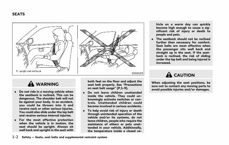
SSS0133
WARNING
. Do not ride in a moving vehicle whenthe seatback is reclined. This can bedangerous. The shoulder belt will notbe against your body. In an accident,you could be thrown into it andreceive neck or other serious injuries.You could also slide under the lap beltand receive serious internal injuries.
. For the most effective protectionwhen the vehicle is in motion, theseat should be upright. Always sitwell back and upright in the seat with
both feet on the floor and adjust theseat belt properly. See “Precautionson seat belt usage” (P.1-9).
. Do not leave children unattendedinside the vehicle. They could un-knowingly activate switches or con-trols. Unattended children couldbecome involved in serious accidents.
. To help avoid risk of injury or deaththrough unintended operation of thevehicle and/or its systems, do notleave children, people who require theassistance of others or pets unat-tended in your vehicle. Additionally,the temperature inside a closed ve-
hicle on a warm day can quicklybecome high enough to cause a sig-nificant risk of injury or death topeople and pets.
. The seatback should not be reclinedfurther than necessary for comfort.Seat belts are most effective whenthe passenger sits well back andstraight up in the seat. If the seat-back is reclined, the risk of slidingunder the lap belt and being injured isincreased.
CAUTION
When adjusting the seat positions, besure not to contact any moving parts toavoid possible injuries and/or damages.
SEATS

FRONT SEATS
Front power seat adjustment
Operating tips:
. The power seat motor has an auto-resetoverload protection circuit. If the motorstops during operation, wait 30 seconds,then reactivate the switch.
. Do not operate the power seat switch fora long period of time when the INFINITIDirect Response Hybrid® System is notrunning. This will discharge the 12-voltbattery.
See “Automatic drive positioner” (P.3-30)for the seat position memory function.
SSS1051
Forward and backward:
Moving the switch forward or backwardwill slide the seat forward or backward tothe desired position.
Reclining:
Move the recline switch backward untilthe desired angle is obtained. To bring theseatback forward again, move the switchforward.
The reclining feature allows adjustment ofthe seatback for occupants of different sizesfor added comfort and to help obtain properseat belt fit. (See “Precautions on seat beltusage” (P.1-9).) Also, the seatback can bereclined to allow occupants to rest when the
vehicle is parked.
Safety — Seats, seat belts and supplemental restraint system 1-3

1-4 Safety — Seats, seat belts and supplemental restraint system
SSS1052
Seat lifter:
Push the front or rear end of the switch up ordown to adjust the angle of the front portionor height of the seat.
SSS1053
Lumbar support (if so equipped):
The lumbar support feature provides lowerback support to the driver.
Push the front or back end of the switch toadjust the seatback lumbar area.
SSS1061
ARMREST
Rear armrestPull the armrest forward until it is horizontal.
WARNING
Head restraints/headrests supplementthe other vehicle safety systems. Theymay provide additional protectionagainst injury in certain rear end colli-sions. Adjustable head restraints/head-rests must be adjusted properly, asspecified in this section. Check theadjustment after someone else uses theseat. Do not attach anything to the headrestraint/headrest stalks or remove thehead restraint/headrest. Do not use theseat if the head restraint/headrest hasbeen removed. If the head restraint/headrest was removed, reinstall andproperly adjust the head restraint/headrest before an occupant uses theseating position. Failure to follow theseinstructions can reduce the effectivenessof the head restraints/headrests. Thismay increase the risk of serious injury ordeath in a collision.
JVR0089X
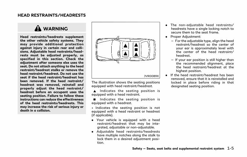
The illustration shows the seating positionsequipped with head restraint/headrest.
Indicates the seating position isequipped with a head restraint.
Indicates the seating position isequipped with a headrest.
+ Indicates the seating position is notequipped with a head restraint or headrest(if applicable).
. Your vehicle is equipped with a headrestraint/headrest that may be inte-grated, adjustable or non-adjustable.
. Adjustable head restraints/headrestshave multiple notches along the stalk tolock them in a desired adjustment posi-tion.
. The non-adjustable head restraints/headrests have a single locking notch tosecure them to the seat frame.
. Proper Adjustment:
— For the adjustable type, align the headrestraint/headrest so the center ofyour ear is approximately level withthe center of the head restraint/headrest.
— If your ear position is still higher thanthe recommended alignment, placethe head restraint/headrest at thehighest position.
. If the head restraint/headrest has beenremoved, ensure that it is reinstalled andlocked in place before riding in thatdesignated seating position.
Safety — Seats, seat belts and supplemental restraint system 1-5
HEAD RESTRAINTS/HEADRESTS
1-6 Safety — Seats, seat belts and supplemental restraint system
SSS0992
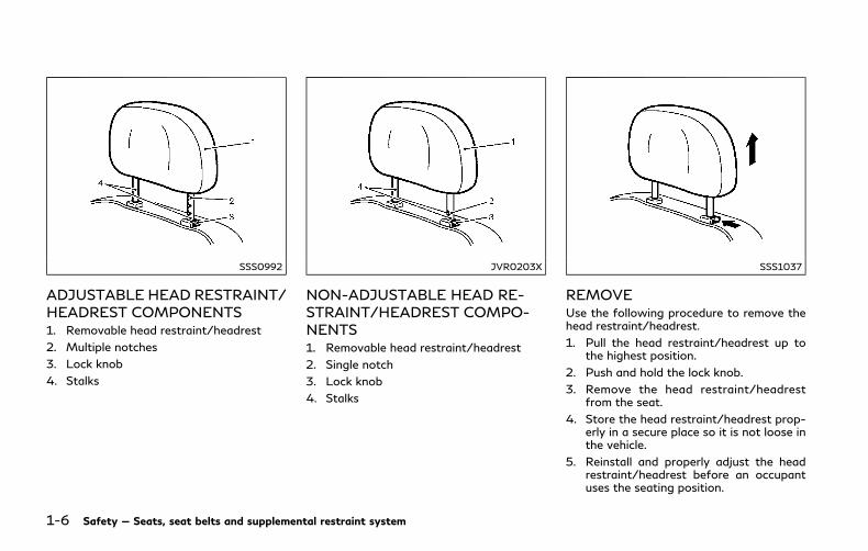
ADJUSTABLE HEAD RESTRAINT/HEADREST COMPONENTS1. Removable head restraint/headrest
2. Multiple notches
3. Lock knob
4. Stalks
JVR0203X
NON-ADJUSTABLE HEAD RE-STRAINT/HEADREST COMPO-NENTS1. Removable head restraint/headrest
2. Single notch
3. Lock knob
4. Stalks
SSS1037
REMOVEUse the following procedure to remove thehead restraint/headrest.
1. Pull the head restraint/headrest up tothe highest position.
2. Push and hold the lock knob.
3. Remove the head restraint/headrestfrom the seat.
4. Store the head restraint/headrest prop-erly in a secure place so it is not loose inthe vehicle.
5. Reinstall and properly adjust the headrestraint/headrest before an occupantuses the seating position.
SSS1038
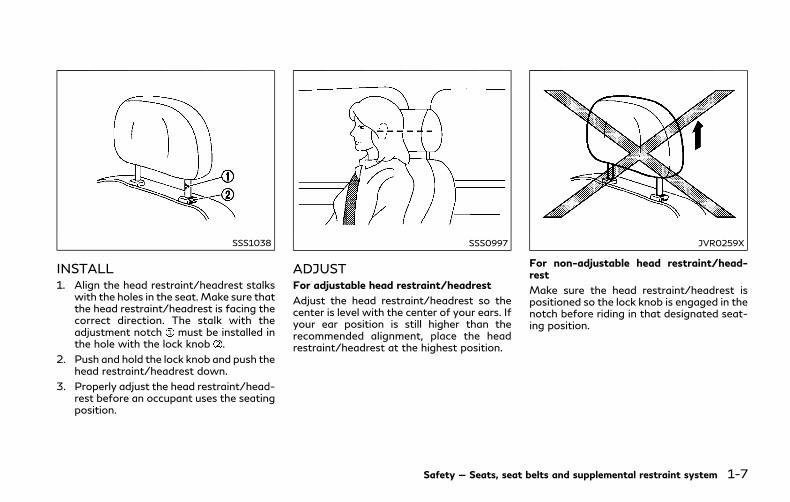
INSTALL1. Align the head restraint/headrest stalks
with the holes in the seat. Make sure thatthe head restraint/headrest is facing thecorrect direction. The stalk with theadjustment notch must be installed inthe hole with the lock knob .
2. Push and hold the lock knob and push thehead restraint/headrest down.
3. Properly adjust the head restraint/head-rest before an occupant uses the seatingposition.
SSS0997
ADJUSTFor adjustable head restraint/headrest
Adjust the head restraint/headrest so thecenter is level with the center of your ears. Ifyour ear position is still higher than therecommended alignment, place the headrestraint/headrest at the highest position.
JVR0259X
For non-adjustable head restraint/head-rest
Make sure the head restraint/headrest ispositioned so the lock knob is engaged in thenotch before riding in that designated seat-ing position.
Safety — Seats, seat belts and supplemental restraint system 1-7

1-8 Safety — Seats, seat belts and supplemental restraint system
SSS1035
RaiseTo raise the head restraint/headrest, pull itup.
Make sure the head restraint/headrest ispositioned so the lock knob is engaged in thenotch before riding in that designated seat-ing position.
SSS1036
LowerTo lower, push and hold the lock knob andpush the head restraint/headrest down.
Make sure the head restraint/headrest ispositioned so the lock knob is engaged in thenotch before riding in that designated seat-ing position.
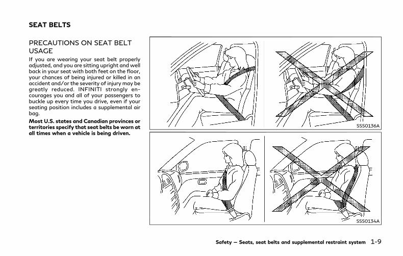
PRECAUTIONS ON SEAT BELTUSAGEIf you are wearing your seat belt properlyadjusted, and you are sitting upright andwellback in your seat with both feet on the floor,your chances of being injured or killed in anaccident and/or the severity of injury may begreatly reduced. INFINITI strongly en-courages you and all of your passengers tobuckle up every time you drive, even if yourseating position includes a supplemental airbag.
Most U.S. states and Canadian provinces orterritories specify that seat belts be worn atall times when a vehicle is being driven.
SSS0136A
SSS0134A
Safety — Seats, seat belts and supplemental restraint system 1-9
SEAT BELTS
1-10 Safety — Seats, seat belts and supplemental restraint system
SSS0016
SSS0014
WARNING
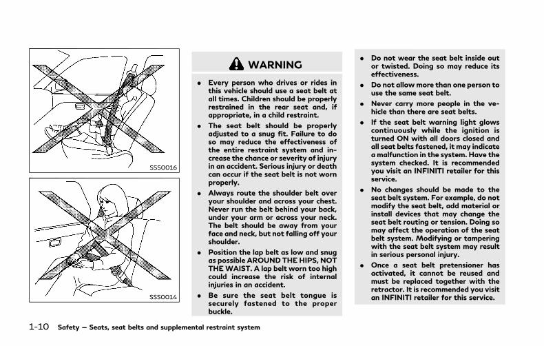
. Every person who drives or rides inthis vehicle should use a seat belt atall times. Children should be properlyrestrained in the rear seat and, ifappropriate, in a child restraint.
. The seat belt should be properlyadjusted to a snug fit. Failure to doso may reduce the effectiveness ofthe entire restraint system and in-crease the chance or severity of injuryin an accident. Serious injury or deathcan occur if the seat belt is not wornproperly.
. Always route the shoulder belt overyour shoulder and across your chest.Never run the belt behind your back,under your arm or across your neck.The belt should be away from yourface and neck, but not falling off yourshoulder.
. Position the lap belt as low and snugas possible AROUND THEHIPS, NOTTHEWAIST. A lap belt worn too highcould increase the risk of internalinjuries in an accident.
. Be sure the seat belt tongue issecurely fastened to the properbuckle.
. Do not wear the seat belt inside outor twisted. Doing so may reduce itseffectiveness.
. Do not allowmore than one person touse the same seat belt.
. Never carry more people in the ve-hicle than there are seat belts.
. If the seat belt warning light glowscontinuously while the ignition isturned ON with all doors closed andall seat belts fastened, it may indicatea malfunction in the system. Have thesystem checked. It is recommendedyou visit an INFINITI retailer for thisservice.
. No changes should be made to theseat belt system. For example, do notmodify the seat belt, add material orinstall devices that may change theseat belt routing or tension. Doing somay affect the operation of the seatbelt system. Modifying or tamperingwith the seat belt system may resultin serious personal injury.
. Once a seat belt pretensioner hasactivated, it cannot be reused andmust be replaced together with theretractor. It is recommended you visitan INFINITI retailer for this service.
. All seat belt assemblies, includingretractors and attaching hardware,should be inspected after any colli-sion. It is recommended you visit anINFINITI retailer for this service.INFINITI recommends that all seatbelt assemblies in use during a colli-sion be replaced unless the collisionwas minor and the belts show nodamage and continue to operateproperly. Seat belt assemblies not inuse during a collision should also beinspected and replaced if either da-mage or improper operation is noted.
. All child restraints and attachinghardware should be inspected afterany collision. Always follow the re-straint manufacturer’s inspection in-s t r u c t i on s and r ep l a c emen trecommendations. The child re-straints should be replaced if theyare damaged.
PREGNANT WOMENINFINITI recommends that pregnant womenuse seat belts. The seat belt should be wornsnug, and always position the lap belt as lowas possible around the hips, not the waist,and place the shoulder belt over yourshoulder and across your chest. Never runthe lap/shoulder belt over your abdominal
area. Contact your doctor for specific re-commendations.
INJURED PERSONSINFINITI recommends that injured personsuse seat belts, depending on the injury.Check with your doctor for specific recom-mendations.
PRE-CRASH SEAT BELTS WITHCOMFORT FUNCTION (frontseats) (if so equipped)The pre-crash seat belt tightens the seat beltwith a motor to help restrain front seatoccupants. This helps reduce the risk ofinjury in a collision.
The motor retracts the seat belt under thefollowing emergency conditions:
. During emergency braking.
. During sudden steering maneuvers.
. Activation of the Forward EmergencyBraking (FEB) system. (See “ForwardEmergency Braking (FEB)” (P.5-104).)
The pre-crash seat belt will not be activewhen:
. The seat belt is not fastened.
. The vehicle speed is under 10 MPH (15km/h) during emergency braking.
. The vehicle speed is under 19 MPH (30km/h) during sudden steering maneu-
vers.
The pre-crash seat belt will not be activewhen the brake pedal is not depressedexcept when sudden steering maneuversoccur or the FEB system activates.
The motor also retracts the seat belt whenthe seat belt is fastened or unfastened.When the seat belt is fastened, the motortightens the seat belt for a snug fit. Whenthe seat belt is unfastened, the motorretracts the seat belt. If the seat belt is notfully retracted, the motor retracts the seatbelt when the door is opened.
Always wear your seat belt correctly and situpright and well back.
If the motor cannot retract the seat beltwhen the seat belt is fastened or unfas-tened, it may indicate the pre-crash seat beltsystem has a malfunction. It is recommendedyou have an INFINITI retailer check andrepair the system.
When the seat belt is retracted repeatedly ina short period of time, the motor may not beable to retract the seat belt. After a fewminutes, the motor normally reactivates andretracts the seat belt. If the seat belt stillcannot be retracted by the motor, the pre-crash seat belt system has a malfunction.Have the system checked and repaired. It isrecommended you visit an INFINITI retailerfor this service.
Safety — Seats, seat belts and supplemental restraint system 1-11

1-12 Safety — Seats, seat belts and supplemental restraint system
THREE-POINT TYPE SEAT BELT
WARNING
. Every person who drives or rides inthis vehicle should use a seat belt atall times.
. Do not ride in a moving vehicle whenthe seatback is reclined. This can bedangerous. The shoulder belt will notbe against your body. In an accident,you could be thrown into it andreceive neck or other serious injuries.You could also slide under the lap beltand receive serious internal injuries.
. For the most effective protectionwhen the vehicle is in motion, theseat should be upright. Always sitwell back and upright in the seat withboth feet on the floor and adjust theseat belt properly.
. Do not allow children to play with theseat belts. Most seating positions areequipped with Automatic LockingRetractor (ALR) mode seat belts. Ifthe seat belt becomes wrappedaround a child’s neck with the ALRmode activated, the child can beseriously injured or killed if the seatbelt retracts and becomes tight. This
can occur even if the vehicle isparked. Unbuckle the seat belt torelease the child. If the seat belt cannot be unbuckled or is already un-buckled, release the child by cuttingthe seat belt with a suitable tool(such as a knife or scissors) to releasethe seat belt.
SSS0292
Fastening the seat belts1. Adjust the seat. (See “Seats” (P.1-2).)
2. Slowly pull the seat belt out of theretractor and insert the tongue into thebuckle until you hear and feel the latchengage.. The retractor is designed to lock
during a sudden stop or on impact.A slow pulling motion permits thebelt to move, and allows you somefreedom of movement in the seat.
. If the seat belt cannot be pulled fromits fully retracted position, firmly pullthe belt and release it. Then smoothlypull the belt out of the retractor.

SSS0290
3. Position the lap belt portion low andsnug on the hips as shown.
4. Pull the shoulder belt portion toward theretractor to take up extra slack. Be surethe shoulder belt is routed over yourshoulder and across your chest.
The three-point type seat belts have twomodes of operation:
. Emergency Locking Retractor (ELR)
. Automatic Locking Retractor (ALR)
The Emergency Locking Retractor (ELR)mode allows the seat belt to extend andretract to allow the driver and passengerssome freedom of movement in the seat. TheELR locks the seat belt when the vehicleslows down rapidly or during impacts.
The Automatic Locking Retractor (ALR)mode (child restraint mode) locks the seatbelt for child restraint installation.
When the ALR mode is activated the seatbelt cannot be extended again until the seatbelt tongue is detached from the buckle andfully retracted. The seat belt returns to theELR mode after the seat belt fully retracts.For additional information, see “Child re-straints” (P.1-18).
The ALR mode should be used only for childrestraint installation. During normal seatbelt use by an occupant, the ALR modeshould not be activated. If it is activated, itmay cause uncomfortable seat belt tension.
WARNING
When fastening the seat belts, be certainthat seatbacks are completely secured inthe latched position. If they are notcompletely secured, passengers may beinjured in an accident or sudden stop.
SSS0326
Unfastening the seat beltsTo unfasten the seat belt, push the buttonon the buckle. The seat belt automaticallyretracts.
Checking seat belt operationSeat belt retractors are designed to lock seatbelt movement by two separate methods:
. When the belt is pulled quickly from theretractor.
. When the vehicle slows down rapidly.
To increase your confidence in the seat belts,check the operation as follows:
. Grasp the shoulder belt and pull forwardquickly. The retractor should lock and
Safety — Seats, seat belts and supplemental restraint system 1-13
1-14 Safety — Seats, seat belts and supplemental restraint system
restrict further belt movement.
If the retractor does not lock during thischeck, get the system checked. It is recom-mended you visit an INFINITI retailer for thisservice, or to learn more about seat beltoperation.
SSS1084
Center of rear seat
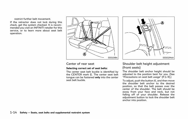
Selecting correct set of seat belts:
The center seat belt buckle is identified bythe CENTER mark . The center seat belttongue can be fastened only into the centerseat belt buckle.
SSS0294A
Shoulder belt height adjustment(front seats)The shoulder belt anchor height should beadjusted to the position best for you. (See“Precautions on seat belt usage” (P.1-9).)
To adjust, push the button , and then movethe shoulder belt anchor to the desiredposition, so that the belt passes over thecenter of the shoulder. The belt should beaway from your face and neck, but notfalling off of your shoulder. Release theadjustment button to lock the shoulder beltanchor into position.

WARNING
. After adjustment, release the adjust-ment button and try to move theshoulder belt anchor up and down tomake sure it is securely fixed inposition.
. The shoulder belt anchor heightshould be adjusted to the positionbest for you. Failure to do so mayreduce the effectiveness of the entirerestraint system and increase thechance or severity of injury in anaccident.
SEAT BELT EXTENDERSIf, because of body size or driving position, itis not possible to properly fit the lap-shoulder belt and fasten it, an extender thatis compatible with the installed seat belts isavailable that can be purchased. The ex-tender adds approximately 8 in (200 mm) oflength and may be used for either the driveror front passenger seating position. It isrecommended you visit an INFINITI retailerfor assistance with purchasing an extender ifan extender is required.
WARNING
. It is recommended only INFINITI seatbelt extenders, made by the samecompany which made the originalequipment seat belts, be used withthe INFINITI seat belts.
. Adults and children who can use thestandard seat belt should not use anextender. Such unnecessary use couldresult in serious personal injury in theevent of an accident.
. Never use seat belt extenders toinstall child restraints. If the childrestraint is not secured properly, thechild could be seriously injured orkilled in a collision or a sudden stop.
SEAT BELT MAINTENANCE. To clean the seat belt webbing, apply a
mild soap solution or any solution re-commended for cleaning upholstery orcarpets. Then, wipe with a cloth andallow the seat belts to dry in the shade.Do not allow the seat belts to retractuntil they are completely dry.
. If dirt builds up in the shoulder belt guideof the seat belt anchors, the seat beltsmay retract slowly. Wipe the shoulder
belt guide with a clean, dry cloth.
. Periodically check to see that the seatbelt and the metal components such asbuckles, tongues, retractors, flexiblewires and anchors work properly. If looseparts, deterioration, cuts or other da-mage on the webbing is found, the entireseat belt assembly should be replaced.
Safety — Seats, seat belts and supplemental restraint system 1-15

1-16 Safety — Seats, seat belts and supplemental restraint system
WARNING
Do not allow children to play with theseat belts. Most seating positions areequipped with Automatic Locking Re-tractor (ALR)mode seat belts. If the seatbelt becomes wrapped around a child’sneck with the ALR mode activated, thechild can be seriously injured or killed ifthe seat belt retracts and becomes tight.This can occur even if the vehicle isparked. Unbuckle the seat belt to releasethe child. If the seat belt can not beunbuckled or is already unbuckled, re-lease the child by cutting the seat beltwith a suitable tool (such as a knife orscissors) to release the seat belt.
Children need adults to help protect them.
They need to be properly restrained.
In addition to the general information in thismanual, child safety information is availablefrom many other sources, including doctors,teachers, government traffic safety offices,and community organizations. Every child isdifferent, so be sure to learn the best way totransport your child.
There are three basic types of child restraintsystems:
. Rear-facing child restraint
. Forward-facing child restraint
. Booster seat
The proper restraint depends on the child’ssize. Generally, infants up to about 1 yearand less than 20 lbs (9 kg) should be placedin rear-facing child restraints. Forward-facing child restraints are available forchildren who outgrow rear-facing child re-straints and are at least 1 year old. Boosterseats are used to help position a vehicle lap/shoulder belt on a child who can no longeruse a forward-facing child restraint.
WARNING
Infants and children need special protec-tion. The vehicle’s seat belts may not fitthem properly. The shoulder belt maycome too close to the face or neck. Thelap belt may not fit over their small hipbones. In an accident, an improperlyfitting seat belt could cause serious orfatal injury. Always use appropriatechild restraints.
All U.S. states and Canadian provinces orterritories require the use of approved childrestraints for infants and small children. See“Child restraints” (P.1-18).
A child restraint may be secured in thevehicle by using either the LATCH (LowerAnchor and Tethers for CHildren) system orwith the vehicle seat belt. See “Child re-straints” (P.1-18) for more information.
INFINITI recommends that all pre-teens andchildren be restrained in the rear seat.Studies show that children are safer whenproperly restrained in the rear seat than inthe front seat.
This is especially important because yourvehicle has a supplemental restraint system(Air bag system) for the front passenger.See “Supplemental restraint system” (P.1-37).
INFANTSInfants up to at least 1 year old should beplaced in a rear-facing child restraint.INFINITI recommends that infants be placedin child restraints that comply with FederalMotor Vehicle Safety Standards or Cana-dian Motor Vehicle Safety Standards. Youshould choose a child restraint that fits yourvehicle and always follow the manufac-turer’s instructions for installation and use.
CHILD SAFETY
SMALL CHILDRENChildren that are over 1 year old and weighat least 20 lbs (9 kg) should remain in a rear-facing child restraint as long as possible upto the height or weight limit of the childrestraint. Children who outgrow the heightor weight limit of the rear-facing childrestraint and are at least 1 year old shouldbe secured in a forward-facing child re-straint with a harness. Refer to the manu-facturer’s instructions for minimum andmaximum weight and height recommenda-tions. INFINITI recommends that small chil-dren be placed in child restraints that complywith Federal Motor Vehicle Safety Stan-dards or Canadian Motor Vehicle SafetyStandards. You should choose a child re-straint that fits your vehicle and alwaysfollow the manufacturer’s instructions forinstallation and use.
LARGER CHILDRENChildren should remain in a forward-facingchild restraint with a harness until they reachthe maximum height or weight limit allowedby the child restraint manufacturer.
Once a child outgrows the height or weightlimit of the harness-equipped forward-fa-cing child restraint, INFINITI recommendsthat the child be placed in a commerciallyavailable booster seat to obtain proper seat
belt fit. For a seat belt to fit properly, thebooster seat should raise the child so thatthe shoulder belt is properly positionedacross the chest and the top, middle portionof the shoulder. The shoulder belt should notcross the neck or face and should not fall offthe shoulder. The lap belt should lie snuglyacross the lower hips or upper thighs, not theabdomen.
A booster seat can only be used in seatingpositions that have a three-point type seatbelt. The booster seat should fit the vehicleseat and have a label certifying that itcomplies with Federal Motor Vehicle SafetyStandards or Canadian Motor VehicleSafety Standards.
A booster seat should be used until the childcan pass the seat belt fit test below:
. Are the child’s back and hips against thevehicle seatback?
. Is the child able to sit without slouching?
. Do the child’s knees bend easily over thefront edge of the seat with feet flat onthe floor?
. Can the child safely wear the seat belt(lap belt low and snug across the hipsand shoulder belt across mid-chest andshoulder)?
. Is the child able to use the properlyadjusted head restraint/headrest?
. Will the child be able to stay in positionfor the entire ride?
Safety — Seats, seat belts and supplemental restraint system 1-17

1-18 Safety — Seats, seat belts and supplemental restraint system
JVR0473X
If you answered no to any of these ques-tions, the child should remain in a boosterseat using a three-point type seat belt.
NOTE:
Laws in some communities may followdifferent guidelines. Check local and stateregulations to confirm your child is using thecorrect restraint system before traveling.
WARNING
Never let a child stand or kneel on anyseat and do not allow a child in the cargoarea. The child could be seriously injuredor killed in a sudden stop or collision.
SSS0099
SSS0100
PRECAUTIONS ON CHILD RE-STRAINTS
WARNING
. Failure to follow the warnings andinstructions for proper use and in-stallation of child restraints couldresult in serious injury or death of achild or other passengers in a suddenstop or collision:
— The child restraint must be usedand installed properly. Alwaysfollow all of the child restraintmanufacturer’s instructions forinstallation and use.
— Infants and children should neverbe held on anyone’s lap. Even thestrongest adult cannot resist theforces of a collision.
— Do not put a seat belt aroundboth a child and another passen-ger.
— INFINITI recommends that allchild restraints be installed in therear seat. Studies show that chil-dren are safer when properly re-strained in the rear seat than inthe front seat. If youmust install a
CHILD RESTRAINTS

forward-facing child restraint inthe front seat, see “Forward-facing child restraint installationusing the seat belts” (P.1-29).
— Even with the INFINITI AdvancedAir Bag System, never install arear-facing child restraint in thefront seat. An inflating air bagcould seriously injure or kill a child.A rear-facing child restraint mustonly be used in the rear seat.
— Be sure to purchase a child re-straint that will fit the child andvehicle. Some child restraints maynot fit properly in your vehicle.
— Child restraint anchor points aredesigned to withstand loads fromchild restraints that are properlyfitted.
— Never use the anchor points foradult seat belts or harnesses.
— A child restraint with a top tetherstrap should not be used in thefront passenger seat.
— Keep seatbacks as upright aspossible after fitting the childrestraint.
— Infants and children should al-ways be placed in an appropriate
child restraint while in the vehicle.
. When the child restraint is not in use,keep it secured with the LATCHsystem or a seat belt. In a suddenstop or collision, loose objects caninjure occupants or damage the ve-hicle.
CAUTION
A child restraint in a closed vehicle canbecome very hot. Check the seatingsurface and buckles before placing achild in the child restraint.
This vehicle is equipped with a universal childrestraint anchor system, referred to as theLATCH (Lower Anchors and Tethers forCHildren) system. Some child restraints in-clude rigid or webbing-mounted attach-ments that can be connected to theseanchors.
For details, see “Lower Anchors and Tethersfor CHildren System (LATCH)” (P.1-20).
If you do not have a LATCH compatible childrestraint, the vehicle seat belts can be used.
Several manufacturers offer child restraintsfor infants and small children of varioussizes. When selecting any child restraint,
keep the following points in mind:
. Choose only a restraint with a labelcertifying that it complies with FederalMotor Vehicle Safety Standard 213 orCanadian Motor Vehicle Safety Stan-dard 213.
. Check the child restraint in your vehicle tobe sure it is compatible with the vehicle’sseat and seat belt system.
. If the child restraint is compatible withyour vehicle, place your child in the childrestraint and check the various adjust-ments to be sure the child restraint iscompatible with your child. Choose achild restraint that is designed for yourchild’s height and weight. Always followall recommended procedures.
. If the combined weight of the child andchild restraint is less than 65 lbs (29.5kg), you may use either the LATCHanchors or the seat belt to install thechild restraint (not both at the sametime).
. If the combined weight of the child andchild restraint is greater than 65 lbs (29.5kg), use the vehicle’s seat belt (not thelower anchors) to install the child re-straint.
. Be sure to follow the child restraintmanufacturer’s instructions for installa-tion.
Safety — Seats, seat belts and supplemental restraint system 1-19

1-20 Safety — Seats, seat belts and supplemental restraint system
All U.S. states and Canadian provinces orterritories require that infants and smallchildren be restrained in an approved childrestraint at all times while the vehicle isbeing operated. Canadian law requires thetop tether strap on forward-facing childrestraints be secured to the designatedanchor point on the vehicle.
SSS0567
Lower Anchors and Tethers forCHildren System (LATCH)Your vehicle is equipped with special anchorpoints that are used with the LATCH (LowerAnchors and Tethers for CHildren) systemcompatible child restraints. This system mayalso be referred to as the ISOFIX or ISOFIXcompatible system. With this system, you donot have to use a vehicle seat belt to securethe child restraint unless the combinedweight of the child and child restraintexceeds 65 lbs (29.5 kg). If the combinedweight of the child and child restraint isgreater than 65 lbs (29.5 kg), use thevehicle’s seat belt (not the lower anchors)to install the child restraint. Be sure to follow
the child restraint manufacturer’s instruc-tions for installation.
LATCH lower anchor
WARNING
Failure to follow the warnings andinstructions for proper use and installa-tion of child restraints could result inserious injury or death of a child or otherpassengers in a sudden stop or collision:
. Attach LATCH system compatiblechild restraints only at the locationsshown in the illustration.
. Do not secure a child restraint in thecenter rear seating position using theLATCH lower anchors. The child re-straint will not be secured properly.
. Inspect the lower anchors by insert-ing your fingers into the lower anchorarea. Feel to make sure there are noobstructions over the anchors such asseat belt webbing or seat cushionmaterial. The child restraint will notbe secured properly if the loweranchors are obstructed.
Child restraint anchorages are designedto withstand only those loads imposedby correctly fitted child restraints. Under
no circumstances are they to be used toattach adult seat belts, or other items orequipment to the vehicle. Doing so coulddamage the child restraint anchorages.The child restraint will not be properlyinstalled using the damaged anchorage,and a child could be seriously injured orkilled in a collision.
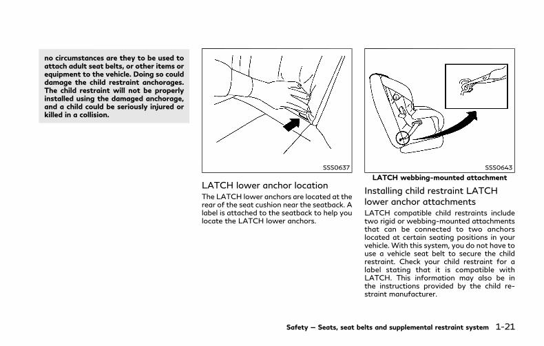
SSS0637
LATCH lower anchor locationThe LATCH lower anchors are located at therear of the seat cushion near the seatback. Alabel is attached to the seatback to help youlocate the LATCH lower anchors.
SSS0643
LATCH webbing-mounted attachment
Installing child restraint LATCHlower anchor attachmentsLATCH compatible child restraints includetwo rigid or webbing-mounted attachmentsthat can be connected to two anchorslocated at certain seating positions in yourvehicle. With this system, you do not have touse a vehicle seat belt to secure the childrestraint. Check your child restraint for alabel stating that it is compatible withLATCH. This information may also be inthe instructions provided by the child re-straint manufacturer.
Safety — Seats, seat belts and supplemental restraint system 1-21

1-22 Safety — Seats, seat belts and supplemental restraint system
SSS0644
LATCH rigid-mounted attachmentWhen installing a child restraint, carefullyread and follow the instructions in thismanual and those supplied with the childrestraint.
JVR0258X
Top tether anchor point locationsAnchor points are located on the rear parcelshelf.
If you have any questions when installing atop tether strap child restraint on the rearseat, it is recommended you visit anINFINITI retailer for this service.
WARNING
Child restraint anchorages are designedto withstand only those loads imposedby correctly fitted child restraints. Underno circumstances are they to be used toattach adult seat belts, or other items or
equipment to the vehicle. Doing so coulddamage the child restraint anchorages.The child restraint will not be properlyinstalled using the damaged anchorage,and a child could be seriously injured orkilled in a collision.
REAR-FACING CHILD RE-STRAINT INSTALLATION USINGLATCHRefer to all Warnings and Cautions in the“Child safety” and “Child restraints” sectionsbefore installing a child restraint.
Do not use the lower anchors if the com-bined weight of the child and the childrestraint exceeds 65 lbs (29.5 kg). If thecombined weight of the child and the childrestraint is greater than 65 lbs (29.5 kg), usethe vehicle’s seat belt (not the lower an-chors) to install the child restraint. Be sure tofollow the child restraint manufacturer’sinstructions for installation.
Follow these steps to install a rear-facingchild restraint using the LATCH system:
1. Position the child restraint on the seat.Always follow the child restraint manu-facturer’s instructions.
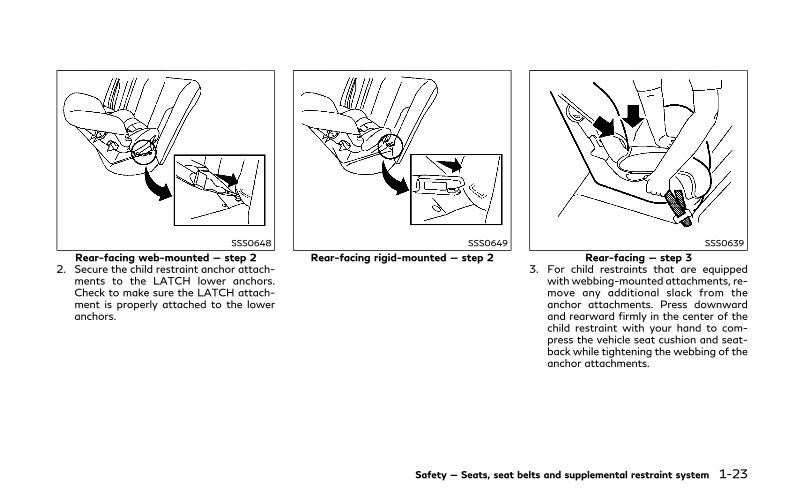
SSS0648
Rear-facing web-mounted — step 22. Secure the child restraint anchor attach-
ments to the LATCH lower anchors.Check to make sure the LATCH attach-ment is properly attached to the loweranchors.
SSS0649
Rear-facing rigid-mounted — step 2
SSS0639
Rear-facing — step 33. For child restraints that are equipped
withwebbing-mounted attachments, re-move any additional slack from theanchor attachments. Press downwardand rearward firmly in the center of thechild restraint with your hand to com-press the vehicle seat cushion and seat-back while tightening the webbing of theanchor attachments.
Safety — Seats, seat belts and supplemental restraint system 1-23
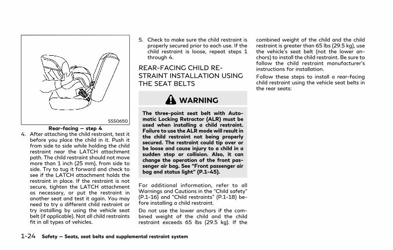
1-24 Safety — Seats, seat belts and supplemental restraint system
SSS0650
Rear-facing — step 44. After attaching the child restraint, test it
before you place the child in it. Push itfrom side to side while holding the childrestraint near the LATCH attachmentpath. The child restraint should not movemore than 1 inch (25 mm), from side toside. Try to tug it forward and check tosee if the LATCH attachment holds therestraint in place. If the restraint is notsecure, tighten the LATCH attachmentas necessary, or put the restraint inanother seat and test it again. You mayneed to try a different child restraint ortry installing by using the vehicle seatbelt (if applicable). Not all child restraintsfit in all types of vehicles.
5. Check to make sure the child restraint isproperly secured prior to each use. If thechild restraint is loose, repeat steps 1through 4.
REAR-FACING CHILD RE-STRAINT INSTALLATION USINGTHE SEAT BELTS
WARNING
The three-point seat belt with Auto-matic Locking Retractor (ALR) must beused when installing a child restraint.Failure to use the ALRmode will result inthe child restraint not being properlysecured. The restraint could tip over orbe loose and cause injury to a child in asudden stop or collision. Also, it canchange the operation of the front pas-senger air bag. See “Front passenger airbag and status light” (P.1-45).
For additional information, refer to allWarnings and Cautions in the “Child safety”(P.1-16) and “Child restraints” (P.1-18) be-fore installing a child restraint.
Do not use the lower anchors if the com-bined weight of the child and the childrestraint exceeds 65 lbs (29.5 kg). If the
combined weight of the child and the childrestraint is greater than 65 lbs (29.5 kg), usethe vehicle’s seat belt (not the lower an-chors) to install the child restraint. Be sure tofollow the child restraint manufacturer’sinstructions for installation.
Follow these steps to install a rear-facingchild restraint using the vehicle seat belts inthe rear seats:
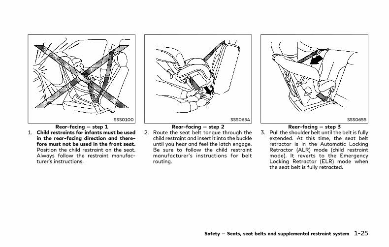
SSS0100
Rear-facing — step 11. Child restraints for infants must be used
in the rear-facing direction and there-fore must not be used in the front seat.Position the child restraint on the seat.Always follow the restraint manufac-turer’s instructions.
SSS0654
Rear-facing — step 22. Route the seat belt tongue through the
child restraint and insert it into the buckleuntil you hear and feel the latch engage.Be sure to follow the child restraintmanufacturer’s instructions for beltrouting.
SSS0655
Rear-facing — step 33. Pull the shoulder belt until the belt is fully
extended. At this time, the seat beltretractor is in the Automatic LockingRetractor (ALR) mode (child restraintmode). It reverts to the EmergencyLocking Retractor (ELR) mode whenthe seat belt is fully retracted.
Safety — Seats, seat belts and supplemental restraint system 1-25

1-26 Safety — Seats, seat belts and supplemental restraint system
SSS0656
Rear-facing — step 44. Allow the seat belt to retract. Pull up on
the shoulder belt to remove any slack inthe belt.
SSS0657
Rear-facing — step 55. Remove any additional slack from the
seat belt; press downward and rearwardfirmly in the center of the child restraintto compress the vehicle seat cushion andseatback while pulling up on the seatbelt.
SSS0658
Rear-facing — step 66. After attaching the child restraint, test it
before you place the child in it. Push itfrom side to side while holding the childrestraint near the seat belt path. Thechild restraint should not move morethan 1 inch (25 mm), from side to side.Try to tug it forward and check to see ifthe belt holds the restraint in place. If therestraint is not secure, tighten the seatbelt as necessary, or put the restraint inanother seat and test it again. You mayneed to try a different child restraint. Notall child restraints fit in all types ofvehicles.
7. Check to make sure that the childrestraint is properly secured prior to each
use. If the seat belt is not locked, repeatsteps 1 through 6.
After the child restraint is removed and theseat belt fully retracted, the ALRmode (childrestraint mode) is canceled.
FORWARD-FACING CHILD RE-STRAINT INSTALLATION USINGLATCHRefer to all Warnings and Cautions in the“Child safety” and “Child restraints” sectionsbefore installing a child restraint.
Do not use the lower anchors if the com-bined weight of the child and the childrestraint exceeds 65 lbs (29.5 kg). If thecombined weight of the child and the childrestraint is greater than 65 lbs (29.5 kg), usethe vehicle’s seat belt (not the lower an-chors) to install the child restraint. Be sure tofollow the child restraint manufacturer’sinstructions for installation.
Follow these steps to install a forward-facing child restraint using the LATCHsystem:
1. Position the child restraint on the seat.Always follow the child restraint manu-facturer’s instructions.
SSS0645
Forward-facing web-mounted — step 22. Secure the child restraint anchor attach-
ments to the LATCH lower anchors.Check to make sure the LATCH attach-ment is properly attached to the loweranchors.
If the child restraint is equipped with atop tether strap, route the top tetherstrap and secure the tether strap to thetether anchor point. See “Installing toptether strap” (P.1-29). Do not install childrestraints that require the use of a toptether strap in seating positions that donot have a top tether anchor.
SSS0646
Forward-facing rigid-mounted — step 23. The back of the child restraint should be
secured against the vehicle seatback.
If necessary, adjust or remove the headrestraint to obtain the correct childrestraint fit. If the head restraint isremoved, store it in a secure place. Besure to reinstall the head restraint whenthe child restraint is removed. See “Headrestraints/headrests” (P.1-5) for headrestraint adjustment information.
If the seating position does not have anadjustable head restraint and it is inter-fering with the proper child restraint fit,try another seating position or a differ-ent child restraint.
Safety — Seats, seat belts and supplemental restraint system 1-27

1-28 Safety — Seats, seat belts and supplemental restraint system
SSS0647
Forward-facing — step 44. For child restraints that are equipped
withwebbing-mounted attachments, re-move any additional slack from theanchor attachments. Press downwardand rearward firmly in the center of thechild restraint with your knee to com-press the vehicle seat cushion and seat-back while tightening the webbing of theanchor attachments.
5. Tighten the tether strap according to themanufacturer’s instructions to removeany slack.
SSS0638
Forward-facing — step 66. After attaching the child restraint, test it
before you place the child in it. Push itfrom side to side while holding the childrestraint near the LATCH attachmentpath. The child restraint should not movemore than 1 inch (25 mm), from side toside. Try to tug it forward and check tosee if the LATCH attachment holds therestraint in place. If the restraint is notsecure, tighten the LATCH attachmentas necessary, or put the restraint inanother seat and test it again. You mayneed to try a different child restraint. Notall child restraints fit in all types ofvehicles.
7. Check to make sure the child restraint isproperly secured prior to each use. If thechild restraint is loose, repeat steps 1through 6.
JVR0258X
Installing top tether strap
WARNING
Child restraint anchorages are designedto withstand only those loads imposedby correctly fitted child restraints. Underno circumstances are they to be used toattach adult seat belts, or other items orequipment to the vehicle. Doing so coulddamage the child restraint anchorages.The child restraint will not be properlyinstalled using the damaged anchorage,and a child could be seriously injured orkilled in a collision.
The child restraint top tether strap must beused when installing the child restraint withthe LATCH lower anchor attachments.
First, secure the child restraint with theLATCH lower anchors (rear outboard seat-ing positions only).
1. Flip up the anchor cover from the anchorpoint which is located directly behind thechild restraint.
2. If necessary, raise or remove the headrestraint or headrest to position the toptether strap over the top of the seatback.If the head restraint or headrest isremoved, store it in a secure place. Besure to reinstall the head restraint orheadrest when the child restraint isremoved.
See “Head restraints/headrests” (P.1-5) for head restraint or headrest adjust-ment, removal and installation informa-tion.
Position the top tether strap over the topof the seatback.
3. Secure the tether strap to the tetheranchor point on the rear parcel shelf.
4. Refer to the appropriate child restraintinstallation procedure steps in this sec-tion before tightening the tether strap.
If you have any questions when installing atop tether strap, it is recommended youvisit an INFINITI retailer for this service.
FORWARD-FACING CHILD RE-STRAINT INSTALLATION USINGTHE SEAT BELTS
WARNING
The three-point seat belt with Auto-matic Locking Retractor (ALR) must beused when installing a child restraint.Failure to use the ALRmode will result inthe child restraint not being properlysecured. The restraint could tip over orbe loose and cause injury to a child in asudden stop or collision. Also, it canchange the operation of the front pas-senger air bag. See “Front passenger airbag and status light” (P.1-45).
Safety — Seats, seat belts and supplemental restraint system 1-29
1-30 Safety — Seats, seat belts and supplemental restraint system
SSS0640
Forward-facing (front passenger seat) —step 1
Refer to all Warnings and Cautions in the“Child safety” and “Child restraints” sectionsbefore installing a child restraint.
Do not use the lower anchors if the com-bined weight of the child and the childrestraint exceeds 65 lbs (29.5 kg). If thecombined weight of the child and the childrestraint is greater than 65 lbs (29.5 kg), usethe vehicle’s seat belt (not the lower an-chors) to install the child restraint. Be sure tofollow the child restraint manufacturer’sinstructions for installation.
Follow these steps to install a forward-facing child restraint using the vehicle seatbelt in the rear seats or in the front
passenger seat:
1. If you must install a child restraint in thefront seat, it should be placed in aforward-facing direction only. Movethe seat to the rearmost position. Childrestraints for infants must be used in therear-facing direction and, therefore,must not be used in the front seat.
2. Position the child restraint on the seat.Always follow the child restraint manu-facturer’s instructions.
The back of the child restraint should besecured against the vehicle seatback.
If necessary, adjust or remove the headrestraint or headrest to obtain thecorrect child restraint fit. If the headrestraint or headrest is removed, store itin a secure place. Be sure to reinstall thehead restraint or headrest when thechild restraint is removed. See “Headrestraints/headrests” (P.1-5) for headrestraint or headrest adjustment, re-moval and installation information.
If the seating position does not have anadjustable head restraint or headrestand it is interfering with the proper childrestraint fit, try another seating positionor a different child restraint.
SSS0360B
Forward-facing — step 33. Route the seat belt tongue through the
child restraint and insert it into the buckleuntil you hear and feel the latch engage.Be sure to follow the child restraintmanufacturer’s instructions for beltrouting.
If the child restraint is equipped with atop tether strap, route the top tetherstrap and secure the tether strap to thetether anchor point (rear seat installationonly). See “Installing top tether strap”(P.1-33). Do not install child restraintsthat require the use of a top tether strapin seating positions that do not have atop tether anchor.
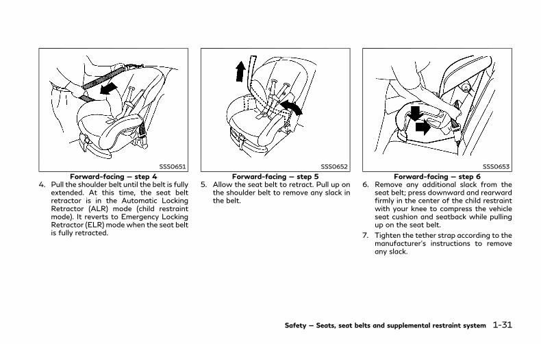
SSS0651
Forward-facing — step 44. Pull the shoulder belt until the belt is fully
extended. At this time, the seat beltretractor is in the Automatic LockingRetractor (ALR) mode (child restraintmode). It reverts to Emergency LockingRetractor (ELR) mode when the seat beltis fully retracted.
SSS0652
Forward-facing — step 55. Allow the seat belt to retract. Pull up on
the shoulder belt to remove any slack inthe belt.
SSS0653
Forward-facing — step 66. Remove any additional slack from the
seat belt; press downward and rearwardfirmly in the center of the child restraintwith your knee to compress the vehicleseat cushion and seatback while pullingup on the seat belt.
7. Tighten the tether strap according to themanufacturer’s instructions to removeany slack.
Safety — Seats, seat belts and supplemental restraint system 1-31

1-32 Safety — Seats, seat belts and supplemental restraint system
SSS0641
Forward-facing — step 88. After attaching the child restraint, test it
before you place the child in it. Push itfrom side to side while holding the childrestraint near the seat belt path. Thechild restraint should not move morethan 1 inch (25 mm), from side to side.Try to tug it forward and check to see ifthe belt holds the restraint in place. If therestraint is not secure, tighten the seatbelt as necessary, or put the restraint inanother seat and test it again. You mayneed to try a different child restraint. Notall child restraints fit in all types ofvehicles.
9. Check to make sure the child restraint isproperly secured prior to each use. If the
seat belt is not locked, repeat steps 2through 8.
JVR0192X
Forward-facing — step 1010. If the child restraint is installed in the
front passenger seat, place the ignitionswitch in the ON position. The frontpassenger air bag status light shouldilluminate. If this light is not illuminated,see “Front passenger air bag and statuslight” (P.1-45). Move the child restraintto another seating position. Have thesystem checked. It is recommended youvisit an INFINITI retailer for this service.
After the child restraint is removed and theseat belt is fully retracted, the ALR mode(child restraint mode) is canceled.
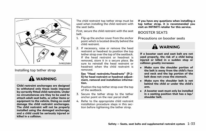
JVR0258X
Installing top tether strap
WARNING
Child restraint anchorages are designedto withstand only those loads imposedby correctly fitted child restraints. Underno circumstances are they to be used toattach adult seat belts, or other items orequipment to the vehicle. Doing so coulddamage the child restraint anchorages.The child restraint will not be properlyinstalled using the damaged anchorage,and a child could be seriously injured orkilled in a collision.
The child restraint top tether strap must beused when installing the child restraint withthe seat belts.
First, secure the child restraint with the seatbelt.
1. Flip up the anchor cover from the anchorpoint which is located directly behind thechild restraint.
2. If necessary, raise or remove the headrestraint or headrest to position the toptether strap over the top of the seatback.If the head restraint or headrest isremoved, store it in a secure place. Besure to reinstall the head restraint orheadrest when the child restraint isremoved.
See “Head restraints/headrests” (P.1-5) for head restraint or headrest adjust-ment, removal and installation informa-tion.
Position the top tether strap over the topof the seatback.
3. Secure the tether strap to the tetheranchor point on the rear parcel shelf.
4. Refer to the appropriate child restraintinstallation procedure steps in this sec-tion before tightening the tether strap.
If you have any questions when installing atop tether strap, it is recommended youvisit an INFINITI retailer for this service.
BOOSTER SEATS
Precautions on booster seats
WARNING
If a booster seat and seat belt are notused properly, the risk of a child beinginjured or killed in a sudden stop orcollision greatly increases:
. Make sure the shoulder portion ofthe belt is away from the child’s faceand neck and the lap portion of thebelt does not cross the stomach.
. Make sure the shoulder belt is notbehind the child or under the child’sarm.
. A booster seat must only be installedin a seating position that has a lap/shoulder belt.
Safety — Seats, seat belts and supplemental restraint system 1-33
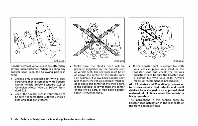
1-34 Safety — Seats, seat belts and supplemental restraint system
LRS0455
Booster seats of various sizes are offered byseveral manufacturers. When selecting anybooster seat, keep the following points inmind:
. Choose only a booster seat with a labelcertifying that it complies with FederalMotor Vehicle Safety Standard 213 orCanadian Motor Vehicle Safety Stan-dard 213.
. Check the booster seat in your vehicle tobe sure it is compatible with the vehicle’sseat and seat belt system.
LRS0453
. Make sure the child’s head will beproperly supported by the booster seator vehicle seat. The seatback must be ator above the center of the child’s ears.For example, if a low back booster seatis chosen, the vehicle seatbackmust be
at or above the center of the child’s ears.If the seatback is lower than the centerof the child’s ears, a high back boosterseat should be used.
LRS0464
. If the booster seat is compatible withyour vehicle, place your child in thebooster seat and check the variousadjustments to be sure the booster seatis compatible with your child. Alwaysfollow all recommended procedures.
All U.S. states and Canadian provinces orterritories require that infants and smallchildren be restrained in an approved childrestraint at all times while the vehicle isbeing operated.
The instructions in this section apply tobooster seat installation in the rear seats orthe front passenger seat.
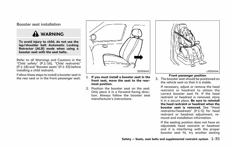
Booster seat installation
WARNING
To avoid injury to child, do not use thelap/shoulder belt Automatic LockingRetractor (ALR) mode when using abooster seat with the seat belts.
Refer to all Warnings and Cautions in the“Child safety” (P.1-16), “Child restraints”(P.1-18) and “Booster seats” (P.1-33) beforeinstalling a child restraint.
Follow these steps to install a booster seat inthe rear seat or in the front passenger seat:
SSS0640
1. If you must install a booster seat in thefront seat, move the seat to the rear-most position.
2. Position the booster seat on the seat.Only place it in a forward-facing direc-tion. Always follow the booster seatmanufacturer’s instructions.
LRS0454
Front passenger position3. The booster seat should be positioned on
the vehicle seat so that it is stable.
If necessary, adjust or remove the headrestraint or headrest to obtain thecorrect booster seat fit. If the headrestraint or headrest is removed, storeit in a secure place. Be sure to reinstallthe head restraint or headrest when thebooster seat is removed. See “Headrestraints/headrests” (P.1-5) for headrestraint or headrest adjustment, re-moval and installation information.
If the seating position does not have anadjustable head restraint or headrestand it is interfering with the properbooster seat fit, try another seating
Safety — Seats, seat belts and supplemental restraint system 1-35

1-36 Safety — Seats, seat belts and supplemental restraint system
position or a different booster seat.
4. Position the lap portion of the seat beltlow and snug on the child’s hips. Be sureto follow the booster seat manufac-turer’s instructions for adjusting the seatbelt routing.
5. Pull the shoulder belt portion of the seatbelt toward the retractor to take upextra slack. Be sure the shoulder belt ispositioned across the top, middle portionof the child’s shoulder. Be sure to followthe booster seat manufacturer’s instruc-tions for adjusting the seat belt routing.
6. Follow the warnings, cautions and in-structions for properly fastening a seatbelt shown in “Seat belts” (P.1-9).
JVR0192X
7. If the booster seat is installed in the frontpassenger seat, push the ignition switchto the ON position. The front passengerair bag status light may or may notilluminate depending on the size of thechild and the type of booster seat used.See “Front passenger air bag and statuslight” (P.1-45).

PRECAUTIONS ON SUPPLE-MENTAL RESTRAINT SYSTEMThis Supplemental Restraint System (SRS)section contains important information con-cerning the following systems:
. Driver and passenger front-impact sup-plemental air bags (INFINITI AdvancedAir Bag System)
. Front seat-mounted side-impact supple-mental air bag
. Roof-mounted curtain side-impact androllover supplemental air bag
. Seat belt with pretensioner
Supplemental front-impact air bag system:The INFINITI Advanced Air Bag System canhelp cushion the impact force to the headand chest of the driver and front passengerin certain frontal collisions.
Front seat-mounted side-impact supple-mental air bag system: This system can helpcushion the impact force to the chest andpelvis area of the driver and front passengerin certain side impact collisions. The side airbag is designed to inflate on the side wherethe vehicle is impacted.
Roof-mounted curtain side-impact and roll-over supplemental air bag system: Thissystem can help cushion the impact forceto the head of occupants in front and rearoutboard seating positions in certain side
impact or rollover collisions. In a side impact,the curtain air bags are designed to inflateon the side where the vehicle is impacted. Ina rollover, the curtain air bags on both sidesare designed to inflate and remain inflatedfor a short time.
Curtain air bags are also designed to inflatein certain types of rollover collisions or nearrollovers. As a result, certain vehicle move-ments may cause the curtain air bags toinflate.
These supplemental restraint systems aredesigned to supplement the crash protectionprovided by the driver and passenger seatbelts and are not a substitute for them. Seatbelts should always be correctly worn andthe occupant seated a suitable distanceaway from the steering wheel, instrumentpanel and door finishers. (See “Seat belts”(P.1-9) for instructions and precautions onseat belt usage.)
The supplemental air bags operate onlywhen the ignition switch is in the ONposition.
After pushing the ignition switch to the ONposition, the supplemental air bag warninglight illuminates. The supplemental air bagwarning light will turn off after about 7seconds if the systems are operational.
Safety — Seats, seat belts and supplemental restraint system 1-37
SUPPLEMENTAL RESTRAINT SYSTEM

1-38 Safety — Seats, seat belts and supplemental restraint system
SSS0131B
SSS0132B
WARNING
. The front air bags ordinarily will notinflate in the event of a side impact,rear impact, rollover, or lower sever-ity frontal collision. Always wearyour seat belts to help reduce therisk or severity of injury in variouskinds of accidents.
. The front passenger air bag will notinflate if the passenger air bag statuslight is lit. See “Front passenger airbag and status light” (P.1-45).
. The seat belts and the front air bagsare most effective when you aresitting well back and upright in theseat with both feet on the floor. Thefront air bags inflate with greatforce. Even with the INFINITI Ad-vanced Air Bag System, if you areunrestrained, leaning forward, sittingsideways or out of position in anyway, you are at greater risk of injuryor death in a crash. You may alsoreceive serious or fatal injuries fromthe front air bag if you are up againstit when it inflates. Always sit backagainst the seatback and as far-awayas practical from the steering wheelor instrument panel. Always use theseat belts.

. The driver and front passenger seatbelt buckles are equipped with sen-sors that detect if the seat belts arefastened. The Advanced Air BagSystem monitors the severity of acollision and seat belt usage theninflates the air bags as needed. Fail-ure to properly wear seat belts canincrease the risk or severity of injuryin an accident.
. The front passenger seat is equippedwith occupant classification sensors(weight sensors) that turn the frontpassenger air bag OFF under someconditions. These sensors are onlyused in this seat. Failure to beproperly seated and wearing the seatbelt can increase the risk or severityof injury in an accident. See “Frontpassenger air bag and status light”(P.1-45).
. Keep hands on the outside of thesteering wheel. Placing them insidethe steering wheel rim could increasethe risk of injury if the front air baginflates.
SSS0007
SSS0006
SSS0008
SSS0009
Safety — Seats, seat belts and supplemental restraint system 1-39
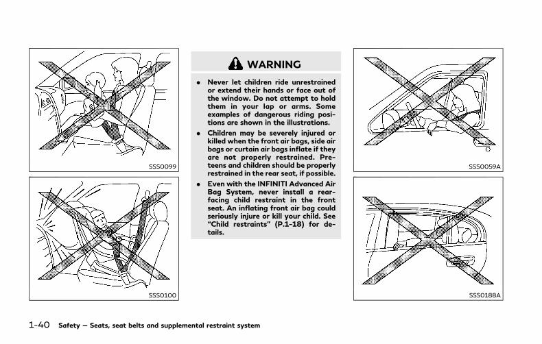
1-40 Safety — Seats, seat belts and supplemental restraint system
SSS0099
SSS0100
WARNING
. Never let children ride unrestrainedor extend their hands or face out ofthe window. Do not attempt to holdthem in your lap or arms. Someexamples of dangerous riding posi-tions are shown in the illustrations.
. Children may be severely injured orkilled when the front air bags, side airbags or curtain air bags inflate if theyare not properly restrained. Pre-teens and children should be properlyrestrained in the rear seat, if possible.
. Even with the INFINITI Advanced AirBag System, never install a rear-facing child restraint in the frontseat. An inflating front air bag couldseriously injure or kill your child. See“Child restraints” (P.1-18) for de-tails.
SSS0059A
SSS0188A

SSS0140
SSS0162
SSS0159
WARNING
Front seat-mounted side-impact supple-mental air bags and roof-mounted cur-t a i n s i d e - impac t and ro l l o ve rsupplemental air bags:
. The side air bags ordinarily will notinflate in the event of a frontalimpact, rear impact, rollover or lowerseverity side collision. Always wearyour seat belts to help reduce the riskor severity of injury in various kindsof accidents.
. The curtain air bags ordinarily willnot inflate in the event of a front
impact, rear impact, or lower severityside collision. Always wear your seatbelts to help reduce the risk orseverity of injury in various kinds ofaccidents.
. The seat belts, side air bags andcurtain air bags are most effectivewhen you are sitting well back andupright in the seat. The side air bagand curtain air bag inflate with greatforce. Do not allow anyone to placetheir hand, leg or face near the sideair bag on the side of the seatback ofthe front seat or near the side roofrails. Do not allow anyone sitting inthe front seats or rear outboard seatsto extend their hand out of thewindow or lean against the door.Some examples of dangerous ridingpositions are shown in the previousillustrations.
. When sitting in the rear seat, do nothold onto the seatback of the frontseat. If the side air bag inflates, youmay be seriously injured. Be espe-cially careful with children, whoshould always be properly restrained.Some examples of dangerous ridingpositions are shown in the illustra-tions.
Safety — Seats, seat belts and supplemental restraint system 1-41

1-42 Safety — Seats, seat belts and supplemental restraint system
. Do not use seat covers on the frontseatbacks. They may interfere withside air bag inflation.
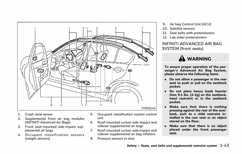
JVR0514X
1. Crash zone sensor
2. Supplemental front air bag modules(INFINITI Advanced Air Bags)
3. Front seat-mounted side-impact sup-plemental air bags
4. Occupant classif ication sensors(weight sensors)
5. Occupant classification system controlunit
6. Roof-mounted curtain side-impact androllover supplemental air bags
7. Roof-mounted curtain side-impact androllover supplemental air bag inflators
8. Pressure sensors in door
9. Air bag Control Unit (ACU)
10. Satellite sensors
11. Seat belts with pretensioners
12. Lap outer pretensioners
INFINITI ADVANCED AIR BAGSYSTEM (front seats)
WARNING
To ensure proper operation of the pas-senger’s Advanced Air Bag System,please observe the following items.
. Do not allow a passenger in the rearseat to push or pull on the seatbackpocket.
. Do not place heavy loads heavierthan 9.1 lbs. (4 kg) on the seatback,head restraint or in the seatbackpocket.
. Make sure that there is nothingpressing against the rear of the seat-back, such as a child restraint in-stalled in the rear seat or an objectstored on the floor.
. Make sure that there is no objectplaced under the front passengerseat.
Safety — Seats, seat belts and supplemental restraint system 1-43
1-44 Safety — Seats, seat belts and supplemental restraint system
. Make sure that there is no objectplaced between the seat cushion andcenter console or between the seatcushion and the door.
. Be sure that the front passenger seatdoes not contact the rear seat, in-strument panel, etc., or the headrestraint does not contact the roof.
. Confirm the operating condition withthe front passenger air bag statuslight.
. If you notice that the front passengerair bag status light is not operatingas described in this section, it isrecommended you visit an INFINITIretailer to check the passenger seatAdvanced Air Bag System.
. Until you have confirmed with aretailer that your passenger seatAdvanced Air Bag System is workingproperly, position the occupants inthe rear seating positions.
. Do not position the front passengerseat so it contacts the rear seat. If thefront seat does contact the rear seat,the air bag system may determine asensor malfunction has occurred andthe front passenger air bag statuslight may illuminate and the supple-mental air bag warning light may
flash.
This vehicle is equipped with the INFINITIAdvanced Air Bag System for the driver andfront passenger seats. This system is de-signed to meet certification requirementsunder U.S. regulations. It is also permitted inCanada.All of the information, cautions andwarnings in this manual apply and must befollowed.
The driver supplemental front-impact airbag is located in the center of the steeringwheel. The front passenger supplementalfront-impact air bag is mounted in theinstrument panel above the glove box. Thefront air bags are designed to inflate inhigher severity frontal collisions, althoughthey may inflate if the forces in another typeof collision are similar to those of a higherseverity frontal impact. They may not inflatein certain frontal collisions. Vehicle damage(or lack of it) is not always an indication ofproper front air bag operation.
The INFINITI Advanced Air Bag System hasdual stage air bag inflators. The systemmonitors information from the crash zonesensor, the Air bag Control Unit (ACU), seatbelt buckle switches and the occupantclassification sensors (weight sensors). In-flator operation is based on the severity of acollision and seat belt usage for the driver.
For the front passenger, the occupantclassification sensors are also monitored.Based on information from the sensors, onlyone front air bag may inflate in a crash,depending on the crash severity andwhetherthe front occupants are belted or unbelted.Additionally, the front passenger air bagmay be automatically turned OFF undersome conditions, depending on the informa-tion provided by the occupant classificationsensors. If the front passenger air bag isOFF, the front passenger air bag status lightwill be illuminated. (See “Front passenger airbag and status light” (P.1-45) for furtherdetails.) One front air bag inflating does notindicate improper performance of the sys-tem.
If you have any questions about your air bagsystem, it is recommended you visit anINFINITI retailer to obtain informationabout the system. If you are consideringmodification of your vehicle due to a dis-ability, you may also contact an INFINITIretailer. Contact information is contained inthe front of this Owner’s Manual.
When a front air bag inflates, a fairly loudnoise may be heard, followed by release ofsmoke. This smoke is not harmful and doesnot indicate a fire. Care should be taken notto inhale it, as it may cause irritation andchoking. Those with a history of a breathingcondition should get fresh air promptly.
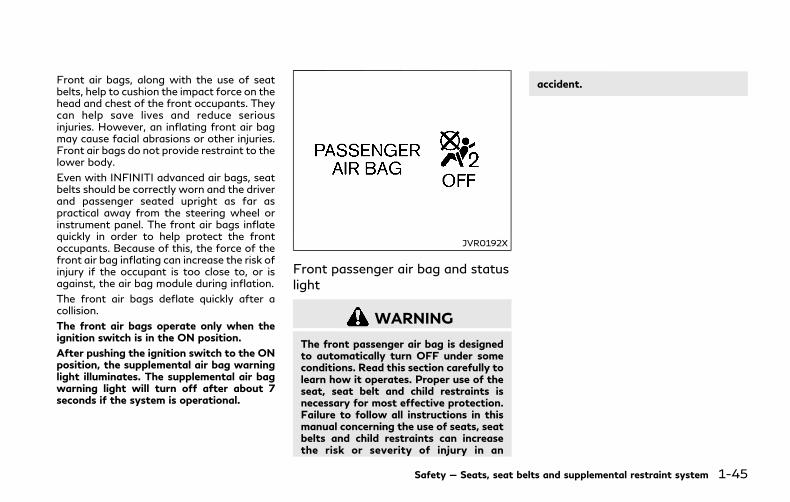
Front air bags, along with the use of seatbelts, help to cushion the impact force on thehead and chest of the front occupants. Theycan help save lives and reduce seriousinjuries. However, an inflating front air bagmay cause facial abrasions or other injuries.Front air bags do not provide restraint to thelower body.
Even with INFINITI advanced air bags, seatbelts should be correctly worn and the driverand passenger seated upright as far aspractical away from the steering wheel orinstrument panel. The front air bags inflatequickly in order to help protect the frontoccupants. Because of this, the force of thefront air bag inflating can increase the risk ofinjury if the occupant is too close to, or isagainst, the air bag module during inflation.
The front air bags deflate quickly after acollision.
The front air bags operate only when theignition switch is in the ON position.
After pushing the ignition switch to the ONposition, the supplemental air bag warninglight illuminates. The supplemental air bagwarning light will turn off after about 7seconds if the system is operational.
JVR0192X
Front passenger air bag and statuslight
WARNING
The front passenger air bag is designedto automatically turn OFF under someconditions. Read this section carefully tolearn how it operates. Proper use of theseat, seat belt and child restraints isnecessary for most effective protection.Failure to follow all instructions in thismanual concerning the use of seats, seatbelts and child restraints can increasethe risk or severity of injury in an
accident.
Safety — Seats, seat belts and supplemental restraint system 1-45
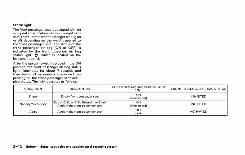
1-46 Safety — Seats, seat belts and supplemental restraint system
Status light:
The front passenger seat is equippedwith anoccupant classification sensors (weight sen-sors) that turn the front passenger air bag onor off depending on the weight applied tothe front passenger seat. The status of thefront passenger air bag (ON or OFF) isindicated by the front passenger air bagstatus light which is located on theinstrument panel.
After the ignition switch is placed in the ONposition, the front passenger air bag statuslight illuminates for about 7 seconds andthen turns off or remains illuminated de-pending on the front passenger seat occu-pied status. The light operates as follows:
CONDITION DESCRIPTIONPASSENGER AIR BAG STATUS LIGHT
( )FRONT PASSENGER AIR BAG STATUS
Empty Empty front passenger seatON
(illuminated)INHIBITED
Nobody/SomebodyBag or Child or Child Restraint or Small
Adult in the front passenger seatON
(illuminated)INHIBITED
Adult Adult in the front passenger seatOFF(dark)
ACTIVATED

In addition to the above, certain objectsplaced on the front passenger seat may alsocause the light to operate as describedabove depending on their weight.
For additional information related to thenormal operation and troubleshooting ofthis occupant classification sensor system,please refer to “Normal operation” (P.1-48)and “Troubleshooting” (P.1-49).
Front passenger air bag:
The front passenger air bag is designed toautomatically turn OFF when the vehicle isoperated under some conditions as de-scribed below in accordance with U.S.regulations. If the front passenger air bagis OFF, it will not inflate in a crash. The driverair bag and other air bags in your vehicle arenot part of this system.
The purpose of the regulation is to helpreduce the risk of injury or death from aninflating air bag to certain front passengerseat occupants, such as children, by requiringthe air bag to be automatically turned OFF.Certain sensors are used to meet therequirements.
The occupant classification sensor in thisvehicle is a weight sensor. It is designed todetect an occupant and objects on the seatby weight. For example, if a child is in thefront passenger seat, the Advanced Air BagSystem is designed to turn the passenger air
bag OFF in accordance with the regulations.Also, if a child restraint of the type specifiedin the regulations is on the seat, its weightand the child’s weight can be detected andcause the air bag to turn OFF.
Front passenger seat adult occupants whoare properly seated and using the seat beltas outlined in this manual should not causethe passenger air bag to be automaticallyturned OFF. For small adults it may beturned OFF, however, if the occupant takeshis/her weight off the seat cushion (forexample, by not sitting upright, by sitting onan edge of the seat, or by otherwise beingout of position), this could cause the sensorto turn the air bag OFF. Always be sure to beseated and wearing the seat belt properlyfor the most effective protection by the seatbelt and supplemental air bag.
INFINITI recommends that pre-teens andchildren be properly restrained in a rear seat.INFINITI also recommends that appropriatechild restraints and booster seats be prop-erly installed in a rear seat. If this is notpossible, the occupant classification sensoris designed to operate as described above toturn the front passenger air bag OFF forspecified child restraints as required by theregulations. Failing to properly secure childrestraints and to use the ALR mode mayallow the restraint to tip or move in acollision or sudden stop. This can also result
in the passenger air bag inflating in a crashinstead of being OFF. For additional infor-mation, refer to “Child restraints” (P.1-18)for proper use and installation.
If the front passenger seat is not occupied,the passenger air bag is designed not toinflate in a crash. However, heavy objectsplaced on the seat could result in air baginflation, because of the object’s weightdetected by the occupant classificationsensor. Other conditions could also result inair bag inflation, such as if a child is standingon the seat, or if two children are on theseat, contrary to the instructions in thismanual. Always be sure that you and allvehicle occupants are seated and restrainedproperly.
Using the front passenger air bag statuslight, you can monitor when the frontpassenger air bag is automatically turnedOFF.
If an adult occupant is in the seat but thefront passenger air bag status light isilluminated (indicating that the air bag isOFF), it could be that the person is a smalladult, or is not sitting on the seat properly ornot using the seat belt properly.
If a child restraint must be used in the frontseat, the front passenger air bag status lightmay or may not be illuminated, depending onthe size of the child and the type of child
Safety — Seats, seat belts and supplemental restraint system 1-47
1-48 Safety — Seats, seat belts and supplemental restraint system
restraint being used. If the front passengerair bag status light is not illuminated (in-dicating that the air bag might inflate in acrash), it could be that the child restraint orseat belt is not being used properly. Makesure that the child restraint is installedproperly, the seat belt is used properly andthe occupant is positioned properly. If thefront passenger air bag status light is still notilluminated, reposition the occupant or childrestraint in a rear seat.
If the front passenger air bag status light willnot illuminate even though you believe thatthe child restraint, the seat belts and theoccupant are properly positioned, it is re-commended that you take your vehicle to anINFINITI retailer. An INFINITI retailer cancheck the system status by using a specialtool. However, until you have confirmedwith your retailer that your air bag is work-ing properly, reposition the occupant or childrestraint in a rear seat.
The INFINITI Advanced Air Bag System andfront passenger air bag status light will takea few seconds to register a change in thepassenger seat status. This is normal opera-tion and does not indicate a malfunction.
If a malfunction occurs in the front passen-ger air bag system, the supplemental air bagwarning light , located in the meter andgauges area of the instrument panel will beilluminated (blinking or steadily lit). Have the
system checked. It is recommended you visitan INFINITI retailer for this service.
Normal operation:
In order for the occupant classificationsensor system to classify the front passen-ger based on weight, please follow theprecautions and steps outlined below:
Precautions
. Make sure that there are no objectsweighing over 9.1 lbs (4 kg) hanging onthe seat or placed in the seatback pocket.
. Make sure that a child restraint or otherobject is not pressing against the rear ofthe seatback.
. Make sure that a rear passenger is notpushing or pulling on the back of thefront passenger seat.
. Make sure that the front passenger seator seatback is not forced back against anobject on the seat or floor behind it.
. Make sure that there is no object placedunder the front passenger seat.
. Make sure that the front passenger seathead restraint does not contact the roofwhen adjusting the front passenger seat.
Steps
1. Adjust the seat as outlined in “Seats”(P.1-2). Sit upright, leaning against theseatback, and centered on the seatcushion with your feet comfortably ex-
tended to the floor.
2. Make sure there are no objects on yourlap.
3. Fasten the seat belt as outlined in “Seatbelts” (P.1-9). Front passenger seat beltbuckle status is monitored by the occu-pant classification sensor system, and isused as an input to determine occupancystatus. So, it is highly recommended thatthe front passenger fastens his/her seatbelt.
4. Remain in this position for 30 secondsallowing the system to classify the frontpassenger before the vehicle is put intomotion.
5. Ensure proper classification by checkingthe front passenger air bag status light.
NOTE:
This vehicle’s occupant classification sensorsystem generally keeps the classificationlocked during driving, so it is important thatyou confirm that the front passenger isproperly classified prior to driving. How-ever, the occupant classification sensor mayrecalculate the weight of the occupantunder some conditions (both while drivingand when stopped), so the front passengerseat occupant should continue to remainseated as outlined above.

Troubleshooting:
If you think the front passenger air bagstatus light is incorrect:
1. If the light is ONwith an adult occupyingthe front passenger seat:. Occupant is a small adult - the air bag
light is functioning as intended. Thefront passenger air bag is suppressed.
However, if the occupant is not a smalladult, then this may be due to thefollowing conditions that may be inter-fering with the weight sensors:. Occupant is not sitting upright, lean-
ing against the seatback, and cen-tered on the seat cushion with his/herfeet comfortably extended to thefloor.
. A child restraint or other object press-ing against the rear of the seatback.
. A rear passenger pushing or pulling onthe back of the front passenger seat.
. Forcing the front seat or seatbackagainst an object on the seat or floorbehind it.
. An object placed under the frontpassenger seat.
. An object placed between the seatcushion and center console or be-tween the seat cushion and the door.
If the vehicle is moving, please come to a
stop when it is safe to do so. Check andcorrect any of the above conditions.Restart the vehicle and wait 1 minute.
NOTE:A system check will be performed duringwhich the front passenger air bag statuslight will remain lit for about 7 secondsinitially.
If the light is still ON after this, theperson should be advised not to ride inthe front passenger seat and the vehicleshould be checked as soon as possible. Itis recommended you visit an INFINITIretailer for this service.
2. If the light is OFFwith a small adult, childor child restraint occupying the frontpassenger seat:
This may be due to the following condi-tions that may be interfering with theweight sensors:. Small adult or child is not sitting
upright, leaning against the seatback,and centered on the seat cushion withhis/her feet comfortably extended tothe floor.
. The child restraint is not properlyinstalled as outlined in “Child re-straints” (P.1-18).
. An object weighing over 9.1 lbs (4 kg)hanging on the seat or placed in theseatback pocket.
. A child restraint or other object press-ing against the rear of the seatback.
. A rear passenger pushing or pulling onthe back of the front passenger seat.
. Forcing the front seat or seatbackagainst an object on the seat or floorbehind it.
. An object placed under the frontpassenger seat.
. An object placed between the seatcushion and center console.
. The front passenger seat head re-straint contacting the roof.
If the vehicle is moving, please come to astop when it is safe to do so. Check andcorrect any of the above conditions.Restart the vehicle and wait 1 minute.
NOTE:A system check will be performed duringwhich the front passenger air bag statuslight will remain lit for about 7 secondsinitially.
If the light is still OFF after this, the smalladult, child or child restraint should berepositioned in the rear seat and thevehicle should be checked as soon aspossible.
3. If the light is OFF with no front passen-ger and no objects on the front passen-ger seat, the vehicle should be checkedas soon as possible. It is recommended
Safety — Seats, seat belts and supplemental restraint system 1-49

1-50 Safety — Seats, seat belts and supplemental restraint system
you visit an INFINITI retailer for thisservice.
Other supplemental front-impactair bag precautions
WARNING
. Do not place any objects on thesteering wheel pad or on the instru-ment panel. Also, do not place anyobjects between any occupant andthe steering wheel or instrumentpanel. Such objects may becomedangerous projectiles and cause in-jury if the front air bags inflate.
. Do not place objects with sharp edgeson the seat. Also, do not place heavyobjects on the seat that will leavepermanent impressions in the seat.Such objects can damage the seat oroccupant classification sensors(weight sensors). This can affect theoperation of the air bag system andresult in serious personal injury.
. Do not use water or acidic cleaners(hot steam cleaners) on the seat. Thiscan damage the seat or occupantclassification sensors. This can alsoaffect the operation of the air bagsystem and result in serious personal
injury.
. Immediately after inflation, severalfront air bag system components willbe hot. Do not touch them; you mayseverely burn yourself.
. No unauthorized changes should bemade to any components or wiring ofthe air bag system. This is to preventaccidental inflation of the supple-mental air bag or damage to thesupplemental air bag system.
. Do not make unauthorized changesto your vehicle’s electrical system,suspension system or front end struc-ture. This could affect proper opera-tion of the front air bag system.
. Tampering with the air bag systemmay result in serious personal injury.Tampering includes changes to thesteering wheel and the instrumentpanel assembly by placing materialover the steering wheel pad andabove the instrument panel or byinstalling additional trim materialaround the air bag system.
. Removing or modifying the frontpassenger seat may affect the func-tion of the air bag system and resultin serious personal injury.
. Modifying or tampering with thefront passenger seat may result inserious personal injury. For example,do not change the front seats byplacing material on the seat cushionor by installing additional trim mate-rial, such as seat covers, on the seatthat is not specifically designed toassure proper air bag operation.Additionally, do not stow any objectsunder the front passenger seat or theseat cushion and seatback. Suchobjects may interfere with the properoperation of the occupant classifica-tion sensors.
. No unauthorized changes should bemade to any components or wiring ofthe seat belt system. This may affectthe front air bag system. Tamperingwith the seat belt system may resultin serious personal injury.
. It is recommended you visit anINFINITI retailer for work on andaround the front air bag. It is alsorecommended you visit an INFINITIretailer for installation of electricalequipment. The Supplemental Re-straint System (SRS) wiring har-nesses* should not be modified ordisconnected. Unauthorized electricaltest equipment and probing devicesshould not be used on the air bag
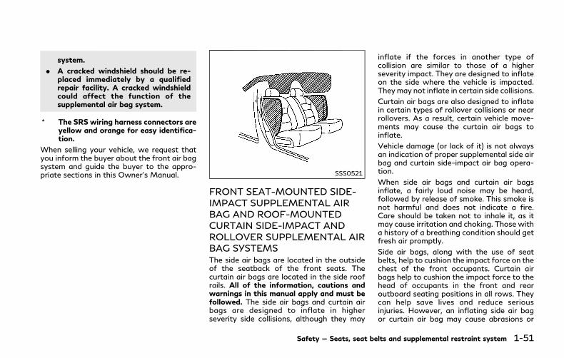
system.
. A cracked windshield should be re-placed immediately by a qualifiedrepair facility. A cracked windshieldcould affect the function of thesupplemental air bag system.
* The SRS wiring harness connectors areyellow and orange for easy identifica-tion.
When selling your vehicle, we request thatyou inform the buyer about the front air bagsystem and guide the buyer to the appro-priate sections in this Owner’s Manual. SSS0521
FRONT SEAT-MOUNTED SIDE-IMPACT SUPPLEMENTAL AIRBAG AND ROOF-MOUNTEDCURTAIN SIDE-IMPACT ANDROLLOVER SUPPLEMENTAL AIRBAG SYSTEMSThe side air bags are located in the outsideof the seatback of the front seats. Thecurtain air bags are located in the side roofrails. All of the information, cautions andwarnings in this manual apply and must befollowed. The side air bags and curtain airbags are designed to inflate in higherseverity side collisions, although they may
inflate if the forces in another type ofcollision are similar to those of a higherseverity impact. They are designed to inflateon the side where the vehicle is impacted.Theymay not inflate in certain side collisions.
Curtain air bags are also designed to inflatein certain types of rollover collisions or nearrollovers. As a result, certain vehicle move-ments may cause the curtain air bags toinflate.
Vehicle damage (or lack of it) is not alwaysan indication of proper supplemental side airbag and curtain side-impact air bag opera-tion.
When side air bags and curtain air bagsinflate, a fairly loud noise may be heard,followed by release of smoke. This smoke isnot harmful and does not indicate a fire.Care should be taken not to inhale it, as itmay cause irritation and choking. Those witha history of a breathing condition should getfresh air promptly.
Side air bags, along with the use of seatbelts, help to cushion the impact force on thechest of the front occupants. Curtain airbags help to cushion the impact force to thehead of occupants in the front and rearoutboard seating positions in all rows. Theycan help save lives and reduce seriousinjuries. However, an inflating side air bagor curtain air bag may cause abrasions or
Safety — Seats, seat belts and supplemental restraint system 1-51

1-52 Safety — Seats, seat belts and supplemental restraint system
other injuries. Side air bags and curtain airbags do not provide restraint to the lowerbody.
The seat belts should be correctly worn andthe driver and passenger seated upright asfar as practical away from the side air bag.Rear seat passengers should be seated as faraway as practical from the door finishersand side roof rails. The side air bags andcurtain air bags inflate quickly in order tohelp protect the occupants. Because of this,the force of the side air bags and curtain airbags inflating can increase the risk of injury ifthe occupant is too close to, or is against,these air bag modules during inflation. Theside air bag will deflate quickly after thecollision is over.
The curtain air bag will remain inflated for ashort time.
The side air bags and curtain air bagsoperate only when the ignition switch is inthe ON position.
After pushing the ignition switch to the ONposition, the supplemental air bag warninglight illuminates. The air bag warning lightwill turn off after about 7 seconds if thesystems are operational.
WARNING
. Do not place any objects near theseatback of the front seats. Also, donot place any objects (an umbrella,bag, etc.) between the front doorfinisher and the front seat. Suchobjects may become dangerous pro-jectiles and cause injury if side air baginflates.
. Right after inflation, several side airbags and curtain air bag systemcomponents will be hot. Do not touchthem; you may severely burn your-self.
. No unauthorized changes should bemade to any components or wiring ofside air bag and curtain air bags. Thisis to prevent damage to or accidentalinflation of the side air bag andcurtain air bag systems.
. Do not make unauthorized changesto your vehicle’s electrical system,suspension system or side panel. Thiscould affect proper operation of theside air bag and curtain air bagsystems.
. Tampering with the air bag systemmay result in serious personal injury.For example, do not change the front
seats by placing material near theseatback or by installing additionaltrim material, such as seat covers,around the side air bags.
. It is recommended you visit anINFINITI retailer for work on andaround the side air bag and curtainair bag. It is also recommended youvisit an INFINITI retailer for installa-tion of electrical equipment. TheSupplemental Restraint System(SRS) wiring harnesses* should notbe modified or disconnected. Un-authorized electrical test equipmentand probing devices should not beused on the side-impact air bagsystem.
* The SRS wiring harness connectors areyellow and orange for easy identifica-tion.
When selling your vehicle, we request thatyou inform the buyer about the side air bagand curtain air bag systems and guide thebuyer to the appropriate sections in thisOwner’s Manual.
SEAT BELTS WITH PRETEN-SIONERS (front seats)
WARNING
. The pretensioners cannot be reusedafter activation. They must be re-placed together with the retractorand buckle as a unit.
. If the vehicle becomes involved in acollision but a pretensioner is notactivated, be sure to have the pre-tensioner system checked and, ifnecessary, replaced. It is recom-mended you visit an INFINITI retailerfor this service.
. No unauthorized changes should bemade to any components or wiring ofthe pretensioners. This is to preventdamage to or accidental activation ofthe pretensioner system. Tamperingwith the pretensioner system mayresult in serious personal injury.
. It is recommended you visit anINFINITI retailer for work on andaround the pretensioner system. It isalso recommended you visit anINFINITI retailer for installation ofelectrical equipment. Unauthorizedelectrical test equipment and probing
devices should not be used on thepretensioner system.
. If you need to dispose of the preten-sioner or scrap the vehicle, it isrecommended you visit an INFINITIretailer for this service. Correct pre-tensioner disposal procedures are setforth in the appropriate INFINITIService Manual. Incorrect disposalprocedures could cause personal in-jury.
The pretensioner system may activate withthe supplemental air bag system in certaintypes of collisions. Working with the seatbelt retractor, it helps tighten the seat beltwhen the vehicle becomes involved in certaintypes of collisions, helping to restrain frontseat occupants.
The pretensioner is encased with the seatbelt retractor. These seat belts are used thesame way as conventional seat belts.
When a pretensioner seat belt activates,smoke is released and a loud noise may beheard. The smoke is not harmful, and it doesnot indicate a fire. Care should be taken notto inhale it as it may cause irritation andchoking. Those with a history of a breathingcondition should get fresh air promptly.
After pretensioner activation, load limitersallow the seat belt to release webbing (if
necessary) to reduce forces against thechest.
The supplemental air bag warning lightis used to indicate malfunctions in thepretensioner system. (See “Supplementalair bag warning light” (P.1-54) for moredetails.) If the operation of the supplementalair bag warning light indicates there is amalfunction, have the system checked. It isrecommended you visit an INFINITI retailerfor this service.
When selling your vehicle, we request thatyou inform the buyer about the seat beltpretensioners and guide the buyer to theappropriate sections in this Owner’s Manual.
Safety — Seats, seat belts and supplemental restraint system 1-53
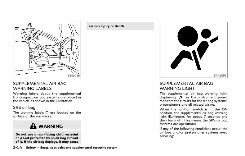
1-54 Safety — Seats, seat belts and supplemental restraint system
SSS1016
SUPPLEMENTAL AIR BAGWARNING LABELSWarning labels about the supplementalfront-impact air bag systems are placed inthe vehicle as shown in the illustration.
SRS air bagThe warning labels are located on thesurface of the sun visors.
WARNING
Do not use a rear-facing child restrainton a seat protected by an air bag in frontof it. If the air bag deploys, it may cause
serious injury or death.
SPA1097
SUPPLEMENTAL AIR BAGWARNING LIGHTThe supplemental air bag warning light,displaying in the instrument panel,monitors the circuits for the air bag systems,pretensioners and all related wiring.
When the ignition switch is in the ONposition, the supplemental air bag warninglight illuminates for about 7 seconds andthen turns off. This means the SRS air bagsystems are operational.
If any of the following conditions occur, theair bag and/or pretensioner systems needservicing:
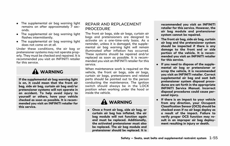
. The supplemental air bag warning lightremains on after approximately 7 sec-onds.
. The supplemental air bag warning lightflashes intermittently.
. The supplemental air bag warning lightdoes not come on at all.
Under these conditions, the air bag orpretensioner systems may not operate prop-erly. They must be checked and repaired. It isrecommended you visit an INFINITI retailerfor this service.
WARNING
If the supplemental air bag warning lightis on, it could mean that the front airbag, side air bag, curtain air bag and/orpretensioner systems will not operate inan accident. To help avoid injury toyourself or others, have your vehiclechecked as soon as possible. It is recom-mended you visit an INFINITI retailer forthis service.
REPAIR AND REPLACEMENTPROCEDUREThe front air bags, side air bags, curtain airbags and pretensioners are designed toactivate on a one-time-only basis. As areminder, unless it is damaged, the supple-mental air bag warning light will remainilluminated after inflation has occurred.These systems should be repaired and/orreplaced as soon as possible. It is recom-mended you visit an INFINITI retailer for thisservice.
When maintenance work is required on thevehicle, the front air bags, side air bags,curtain air bags, pretensioners and relatedparts should be pointed out to the personconducting the maintenance. The ignitionswitch should always be in the LOCKposition when working under the hood orinside the vehicle.
WARNING
. Once a front air bag, side air bag, orcurtain air bag has inflated, the airbag module will not function againand must be replaced. Additionally,the activated pretensioner must alsobe replaced. The air bag module andpretensioner should be replaced. It is
recommended you visit an INFINITIretailer for this service. However, theair bag module and pretensionersystem cannot be repaired.
. The front air bag, side air bag, curtainair bag and the pretensioner systemshould be inspected if there is anydamage to the front end or sideportion of the vehicle. It is recom-mended you visit an INFINITI retailerfor this service.
. If you need to dispose of the supple-mental air bag or pretensioner orscrap the vehicle, it is recommendedyou visit an INFINITI retailer. Correctsupplemental air bag and seat beltpretensioner system disposal proce-dures are set forth in the appropriateINFINITI Service Manual. Incorrectdisposal procedures could cause per-sonal injury.
. If there is an impact to your vehiclefrom any direction, your OccupantClassification Sensor (OCS) should bechecked even if no air bags deploy asa result of the impact. Failure toverify proper OCS function may re-sult in an improper air bag deploy-ment resulting in injury or death.
Safety — Seats, seat belts and supplemental restraint system 1-55

1-56 Safety — Seats, seat belts and supplemental restraint system
MEMO

2 Instruments and controls
Cockpit ................................................................................. 2-3
Instrument panel................................................................ 2-4
Meters and gauges ........................................................... 2-5
Speedometer and odometer ..................................... 2-6
Tachometer..................................................................... 2-7
Assist charge gauge ..................................................... 2-7
Fuel gauge ...................................................................... 2-7
Warning lights, indicator lights andaudible reminders .............................................................. 2-9
Checking lights ............................................................. 2-9
Warning lights............................................................... 2-9
Indicator lights ............................................................ 2-15
Audible reminders ...................................................... 2-17
Vehicle information display .......................................... 2-18
Indicators for operation ........................................... 2-20
Indicators for maintenance ..................................... 2-25
Trip computer ............................................................. 2-27
Clock and outside air temperature ...................... 2-30
Security systems .............................................................. 2-31
Vehicle Security System........................................... 2-31
INFINITI Vehicle Immobilizer System .................. 2-32
Wiper and washer switch ............................................. 2-34
Rain-sensing auto wiper system ........................... 2-35
Rear window and outside mirrordefroster switch............................................................... 2-36
Headlight and turn signal switch ............................... 2-36
Headlight switch ...................................................... 2-36
Turn signal switch.................................................... 2-42
Fog light switch........................................................ 2-43
Horn.................................................................................... 2-43
Vehicle Dynamic Control (VDC) OFF switch.......... 2-43
Heated seats ................................................................... 2-44
Operation with switch............................................ 2-45
Operation with touch screen................................ 2-45
AUTO mode setting ................................................ 2-45
Heated steering wheel .................................................. 2-45
Power outlet .................................................................... 2-46
Ashtray .............................................................................. 2-47
Rear ............................................................................. 2-47
Storage .............................................................................. 2-47
Cup holders................................................................ 2-47
Soft bottle holder ................................................... 2-48
Sunglasses holder .................................................... 2-49
Glove box ................................................................... 2-49
Console box .............................................................. 2-50
Card holder ............................................................... 2-50
Storage box .............................................................. 2-50
Coat hooks ................................................................ 2-51
Trunk hooks ............................................................... 2-51
Windows ............................................................................ 2-52
Power windows ......................................................... 2-52
Moonroof .......................................................................... 2-54
Power moonroof ........................................................ 2-54
Interior lights .................................................................... 2-56
Map lights .................................................................... 2-56
Console light (if so equipped) ................................. 2-56
Personal lights ............................................................ 2-57
Interior light control switch .................................... 2-57
Vanity mirror lights ......................................................... 2-58
Trunk light ......................................................................... 2-58
Courtesy light .................................................................. 2-59
HomeLink® Universal Transceiver ............................. 2-59
Programming HomeLink® .................................... 2-60
Programming HomeLink® for Canadiancustomers and gate openers ................................ 2-61
Operating the HomeLink®
Universal Transceiver.............................................. 2-61
Programming troubleshooting ............................. 2-62
Clearing the programmed information .............. 2-62
Reprogramming a singleHomeLink® button .................................................. 2-62
If your vehicle is stolen........................................... 2-62

JVC1106X
1. Side ventilator (P.4-2)
2. Headlight, fog light and turn signalswitch (P.2-36)
3. Steering wheel
— Horn (P.2-43)
— Driver supplemental air bag (P.1-37)
— Heated steering wheel (P.2-45)
— Power steering (P.5-126)
4. Windshield wiper and washer switch(P.2-34)
5. Hazard warning flasher switch (P.6-2)
6. Shift lever (P.5-15)
7. INFINITI controller*
8. Vehicle Dynamic Control (VDC) OFFswitch (P.2-43, P.5-130)
9. Trunk lid release switch (P.3-22)
10. Instrument brightness control switch(P.2-42)
11. TRIP/RESET switch for twin trip od-ometer (P.2-6)
12. Electric tilting/telescopic steeringwheel switch (P.3-27)
13. Steering-wheel-mounted controls (leftside)
— Audio control steering switch*
— Hands-Free Phone System switch*
— Voice recognition system switch*
14. Steering-wheel-mounted controls(right side)
— Trip computer switch (P.2-27)
— Cruise control switches (if soequipped) (P.5-70)
— Intelligent Cruise Control (ICC)switches (if so equipped) (P.5-72)
— Dynamic driver assistance switch(P.5-24, P.5-32, P.5-47, P.5-93)
15. INFINITI Drive Mode Selector (P.5-21)
*: Refer to the Infiniti InTouch Owner’sManual.
Instruments and controls 2-3
COCKPIT
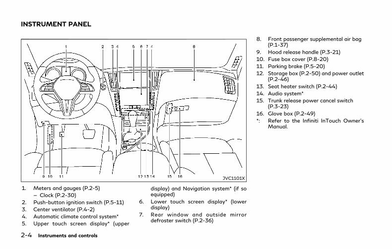
2-4 Instruments and controls
JVC1101X
1. Meters and gauges (P.2-5)
— Clock (P.2-30)
2. Push-button ignition switch (P.5-11)
3. Center ventilator (P.4-2)
4. Automatic climate control system*
5. Upper touch screen display* (upper
display) and Navigation system* (if soequipped)
6. Lower touch screen display* (lowerdisplay)
7. Rear window and outside mirrordefroster switch (P.2-36)
8. Front passenger supplemental air bag(P.1-37)
9. Hood release handle (P.3-21)
10. Fuse box cover (P.8-20)
11. Parking brake (P.5-20)
12. Storage box (P.2-50) and power outlet(P.2-46)
13. Seat heater switch (P.2-44)
14. Audio system*
15. Trunk release power cancel switch(P.3-23)
16. Glove box (P.2-49)
*: Refer to the Infiniti InTouch Owner’sManual.
INSTRUMENT PANEL
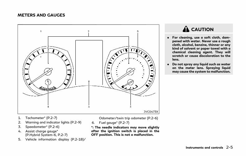
JVC0473X
1. Tachometer* (P.2-7)
2. Warning and indicator lights (P.2-9)
3. Speedometer* (P.2-6)
4. Assist charge gauge*(P.Hybrid System-6, P.2-7)
5. Vehicle information display (P.2-18)/
Odometer/twin trip odometer (P.2-6)
6. Fuel gauge* (P.2-7)
*: The needle indicators may move slightlyafter the ignition switch is placed in theOFF position. This is not a malfunction.
CAUTION
. For cleaning, use a soft cloth, dam-pened with water. Never use a roughcloth, alcohol, benzine, thinner or anykind of solvent or paper towel with achemical cleaning agent. They willscratch or cause discoloration to thelens.
. Do not spray any liquid such as wateron the meter lens. Spraying liquidmay cause the system tomalfunction.
Instruments and controls 2-5
METERS AND GAUGES
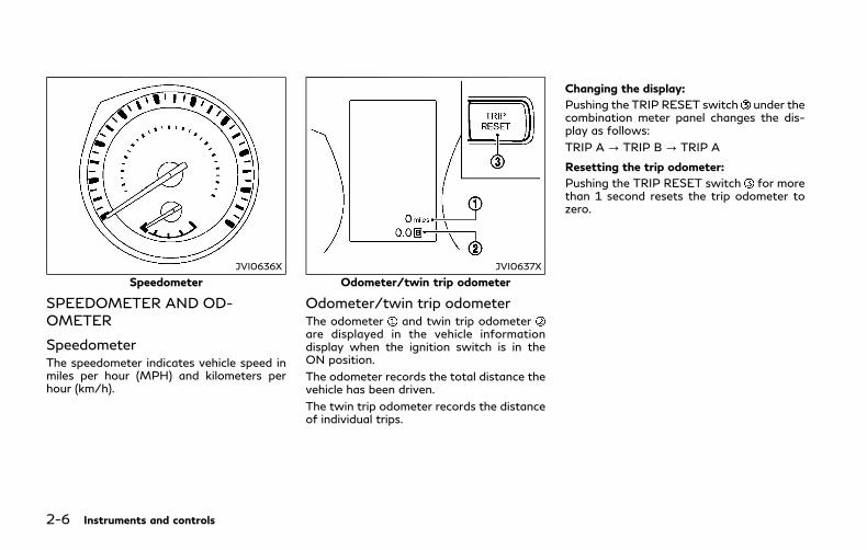
2-6 Instruments and controls
JVI0636X
Speedometer
SPEEDOMETER AND OD-OMETER
SpeedometerThe speedometer indicates vehicle speed inmiles per hour (MPH) and kilometers perhour (km/h).
JVI0637X
Odometer/twin trip odometer
Odometer/twin trip odometerThe odometer and twin trip odometerare displayed in the vehicle informationdisplay when the ignition switch is in theON position.
The odometer records the total distance thevehicle has been driven.
The twin trip odometer records the distanceof individual trips.
Changing the display:
Pushing the TRIP RESET switch under thecombination meter panel changes the dis-play as follows:
TRIP A ? TRIP B ? TRIP A
Resetting the trip odometer:
Pushing the TRIP RESET switch for morethan 1 second resets the trip odometer tozero.

JVI0733X
TACHOMETERThe tachometer indicates engine speed inrevolutions per minute (RPM). Do not revthe engine into the red zone .
The scale length and the red zone vary withthe engine model.
CAUTION
When engine speed approaches the redzone, shift to a higher gear or reduceengine speed. Operating the engine inthe red zone may cause serious enginedamage.
JVI0683X
ASSIST CHARGE GAUGEThe gauge indicates the condition of theelectric motor.
When the needle is between the center and“charge” side, this indicates that theelectric motor is generating power to re-charge the Li-ion battery.
When the needle is between the center andthe PWR side, this indicates that theelectric motor is powering the drive wheelsand the Li-ion battery is discharging.
JVI0640X
FUEL GAUGEThe gauge indicates the approximate fuellevel in the tank.
The gauge may move slightly during braking,turning, acceleration, or going up or downhills.
The gauge needle returns to “0” (Empty)after the ignition switch is pushed to theOFF position.
Refill the fuel tank before the gaugeregisters “0” (Empty).
The low fuel warning light illuminates onthe meter when the fuel level is getting low.Refuel as soon as it is convenient, preferablybefore the gauge reaches “0”. There will be a
Instruments and controls 2-7

2-8 Instruments and controls
small reserve of fuel in the tank when thefuel gauge needle reaches “0”.
The indicates that the fuel-filler door islocated on the right side of the vehicle.
CAUTION
. If the vehicle runs out of fuel, themalfunction indicator light (MIL) maycome on. Refuel as soon as possible.After a few driving trips, thelight should turn off. If the lightremains on after a few driving trips,have the vehicle inspected. It isrecommended you visit an INFINITIretailer for this service.
. For additional information, see “Mal-function Indicator Light (MIL)” (P.2-16).
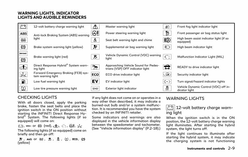
12-volt battery charge warning light Master warning light Front fog light indicator light
Anti-lock Braking System (ABS) warninglight
Power steering warning light Front passenger air bag status light
Seat belt warning light and chimeHigh beam assist indicator light (if soequipped)
Brake system warning light (yellow) Supplemental air bag warning light High beam indicator light
Brake warning light (red)Vehicle Dynamic Control (VDC) warninglight
Malfunction Indicator Light (MIL)
Direct Response Hybrid® System warn-ing light
Approaching Vehicle Sound for Pedes-trians (VSP) OFF indicator light
READY to drive indicator light
Forward Emergency Braking (FEB) sys-tem warning light
ECO drive indicator light Security indicator light
Low fuel warning light EV indicator light Turn signal/hazard indicator lights
Low tire pressure warning light Exterior light indicatorVehicle Dynamic Control (VDC) off in-dicator light
CHECKING LIGHTSWith all doors closed, apply the parkingbrake, fasten the seat belts and place theignition switch in the ON position withoutstarting the INFINITI Direct Response Hy-brid® System. The following lights (if soequipped) will come on:
, or (red), , , ,
The following lights (if so equipped) come onbriefly and then go off:
, or , , , , ,(yellow)
If any light does not come on or operates in away other than described, it may indicate aburned-out bulb and/or a system malfunc-tion. It is recommended you have the systemchecked by an INFINITI retailer.
Some indicators and warnings are alsodisplayed in the vehicle information displaybetween the speedometer and tachometer.(See “Vehicle information display” (P.2-18).)
WARNING LIGHTS
12-volt battery charge warn-ing lightWhen the ignition switch is in the ONposition, the 12-volt battery charge warninglight illuminates. After starting the hybridsystem, the light turns off.
If the light continues to illuminate afterstarting the hybrid system, it may indicatethe charging system is not functioning
Instruments and controls 2-9
WARNING LIGHTS, INDICATORLIGHTS ANDAUDIBLE REMINDERS
2-10 Instruments and controls
properly. It is recommended you visit anINFINITI retailer immediately.
CAUTION
The charging system may not be func-tioning properly if the 12-volt batterycharge warning light comes on while thehybrid system is running. The hybridsystem will stop operating when the12-volt battery becomes discharged.Immediately stop the vehicle in a safeplace and it is recommended you contactan INFINITI retailer.
or Anti-lock BrakingSystem (ABS) warning lightWhen the ignition switch is in the ONposition, the Anti-lock Braking System(ABS) warning light illuminates and thenturns off. This indicates the ABS is opera-tional.
If the ABSwarning light illuminates while thehybrid system is running, or while driving, itmay indicate the ABS is not functioningproperly. Have the system checked. It isrecommended you visit an INFINITI retailerfor this service.
If an ABS malfunction occurs, the anti-lockfunction is turned off. The brake system thenoperates normally, but without anti-lockassistance. (See “Anti-lock Braking System(ABS)” (P.5-129).)
Brake system warning light(yellow)This light will illuminate after the hybridsystem is started and then turns off after afew seconds.
WARNING
If both the brake system warning light(yellow) and the brake warning light(red) illuminate when the parking brakeis released and the hybrid system is on,do not drive the vehicle. More brakepedal effort than normal will be requiredand there will be a significant reductionin brake performance, which could resultin an accident. Immediately stop thevehicle in a safe location and it isrecommended you contact an INFINITIretailer.
If the brake system warning light (yellow)illuminates when the ignition switch is in theON position, it may indicate a malfunction in
the brake system or one of the followingother functions.
. Regenerative brake system
. Hill start assist system
. Rise-up and build-up function
It is recommended you see an INFINITIretailer for an inspection as soon as possible.
A chime sounds if a malfunction occurs in thebrake system power supply.
or Brake warning light(red)This light functions for both the parkingbrake and the foot brake systems.
Parking brake indicator:
When the ignition switch is in the ONposition, the light comes on when theparking brake is applied.
Low brake fluid warning:
When the ignition switch is in the ONposition, the light warns of a low brake fluidlevel. If the light comes on with the parkingbrake not applied, stop the vehicle andperform the following:
1. Check the brake fluid level. If brake fluidis low, add fluid and have the systemchecked. It is recommended you have thisservice performed by an INFINITI retai-

ler. (See “Brake fluid” (P.8-12).)
2. If the brake fluid level is correct, have thewarning system checked. It is recom-mended you have this service performedby an INFINITI retailer.
Brake system malfunction warning:
If the brake warning light (red) and thefollowing warning light illuminate at thesame time when the parking brake is re-leased and the brake fluid level is sufficient,there may be a malfunction in the brakesystem.
. Brake system warning light (yellow)
WARNING
If both the brake system warning light(yellow) and the brake warning light(red) illuminate when the parking brakeis released and the hybrid system is on,do not drive the vehicle. More brakepedal effort than normal will be requiredand there will be a significant reductionin brake performance, which could resultin an accident. Immediately stop thevehicle in a safe location and it isrecommended you contact an INFINITIretailer.
A chime sounds if a malfunction occurs in the
brake system power supply.
. Anti-lock Braking System (ABS) warninglight
— Avoid driving at high speed and sud-den braking, and see an INFINITIretailer as soon as possible for aninspection.
WARNING
. Your brake system may not be work-ing properly if the brake warninglight (red) is on. Driving could bedangerous. If you judge it to be safe,drive carefully to the nearest servicestation for repairs. Otherwise, haveyour vehicle towed because driving itcould be dangerous.
. Pressing the brake pedal with thehybrid system stopped and/or lowbrake fluid level may increase yourstopping distance and braking willrequire greater pedal effort as well aspedal travel.
. If the brake fluid level is below theminimum or MIN mark on the brakefluid reservoir, do not drive until thebrake system has been checked. It isrecommended you visit an INFINITIretailer for this service.
Direct Response Hybrid® Sys-tem warning lightWhen the ignition switch is in the ONposition, the Direct Response Hybrid® Sys-tem (hybrid system) warning light illumi-nates. After starting the hybrid system, thehybrid system warning light turns off.
If the hybrid systemwarning light illuminateswhile driving, it may indicate that there is amalfunction in the electric motor and/orother hybrid system components.
Stop your vehicle immediately and it isrecommended that you contact yourINFINITI retailer.
If the hybrid system warning light blinkswhile driving, it may indicate that the Li-ionbattery charge is low and you cannotcontinue to drive.
Do not allow the vehicle to coast when theLi-ion battery is low or when the hybridsystem warning light blinks while driving.The engine will not automatically start tocharge the Li-ion battery while the vehicle iscoasting.
Forward Emergency Braking(FEB) system warning lightThis light comes on when the ignition switchis placed in the ON position. It turns off after
Instruments and controls 2-11

2-12 Instruments and controls
the hybrid system is started.
This light illuminates when the FEB system isset to OFF on the lower display.
If the light illuminates when the FEB systemis ON, it may indicate that the system isunavailable. See “Forward Emergency Brak-ing (FEB)” (P.5-104) for more details.
Low fuel warning lightThis light illuminates when the fuel in thetank is getting low. Refuel as soon as it isconvenient, preferably before the fuel gaugereaches the 0 (empty) position.
There will be a small reserve of fuel remain-ing in the tank when the fuel gauge reachesthe 0 position.
Low tire pressurewarning lightYour vehicle is equipped with a Tire PressureMonitoring System (TPMS) that monitorsthe tire pressure of all tires.
The low tire pressure warning light warns oflow tire pressure and flat tire, or indicatesthat the TPMS is not functioning properly.
After the ignition switch is placed in the ONposition, this light illuminates for about 1second and turns off.
Low tire pressure warning:
If the vehicle is being driven with low tirepressure, the warning light will illuminate.The “Tire Pressure Low - Add Air” warningalso appears in the vehicle information dis-play.
When the low tire pressure warning lightilluminates, you should stop and adjust thetire pressure to the recommended COLD tirepressure shown on the Tire and LoadingInformation label. The low tire pressurewarning light does not automatically turnoff when the tire pressure is adjusted. Afterthe tire is inflated to the recommendedpressure, the vehicle must be driven atspeeds above 16MPH (25 km/h) to activatethe TPMS and turn off the low tire pressurewarning light. Use a tire pressure gauge tocheck the tire pressure.
The “Tire Pressure Low - Add Air” warning isactive as long as the low tire pressurewarning light remains illuminated.
For additional information, see “Vehicleinformation display” (P.2-18), “Tire PressureMonitoring System (TPMS)” (P.5-5) and“Tire Pressure Monitoring System (TPMS)”(P.6-3).
Flat tire warning:
The flat tire warning warns of a flat tire.
If the vehicle is being drivenwith one or more
flat tires, the low tire pressure warning lightwill illuminate continuously and a chime willsound for 10 seconds. A “Flat Tire - Visitdealer” warning also appears in the vehicleinformation display.
The chime will only sound at the firstindication of a flat tire and the warning lightwill illuminate continuously. When the flattire warning is activated, have the systemreset and the tire checked, and replaced ifnecessary. It is recommended you visit anINFINITI retailer for these services. Even ifthe tire is inflated to the specified COLD tirepressure, the warning light will continue toilluminate until the system is reset.
Your vehicle can be driven for a limited timeon a flat tire. See “Run-flat tires” (P.6-4) and“Run-flat tires” (P.8-34).
TPMS malfunction:
If the TPMS is not functioning properly, thelow tire pressure warning light will flash forapproximately 1 minute when the ignitionswitch is placed in the ON position. The lightwill remain on after the 1 minute. Have thesystem checked. It is recommended you visitan INFINITI retailer for this service. The “TirePressure Low - Add Air” warning does notappear if the low tire pressure warning lightilluminates to indicate a TPMS malfunction.
For additional information, see “Tire Pres-sure Monitoring System (TPMS)” (P.5-5).
WARNING
. Radio waves could adversely affectelectric medical equipment. Thosewho use a pacemaker should contactthe electric medical equipment man-ufacturer for the possible influencesbefore use.
. If the light does not illuminate withthe ignition switch pushed ON, havethe vehicle checked as soon as possi-ble. It is recommended you visit anINFINITI retailer for this service.
. If the light illuminates while driving,avoid sudden steering maneuvers orabrupt braking, reduce vehicle speed,pull off the road to a safe locationand stop the vehicle as soon aspossible. Driving with under-inflatedtires may permanently damage thetires and increase the likelihood oftire failure. Serious vehicle damagecould occur and may lead to anaccident and could result in seriouspersonal injury. Check the tire pres-sure for all four tires. Adjust the tirepressure to the recommended COLDtire pressure shown on the Tire andLoading Information label to turn thelow tire pressure warning light OFF.If the light still illuminates while
driving after adjusting the tire pres-sure, a tire may be flat or the TPMSmay be malfunctioning. If no tire isflat and all tires are properly inflated,it is recommended you consult anINFINITI retailer.
. Although you can continue drivingwith a punctured run-flat tire, re-member that vehicle handling stabi-lity is reduced, which could lead to anaccident and personal injury. Also,driving a long distance at high speedsmay damage the tires.
. Do not drive at speeds above 50MPH (80 km/h) and do not drivemore than approximately 93 miles(150 km) with a punctured run-flattire. The actual distance the vehiclecan be driven on a flat tire depends onoutside temperature, vehicle load,road conditions and other factors.
. If you detect any unusual sounds orvibrations while driving with a punc-tured run-flat tire, pull off the roadto a safe location and stop the vehicleas soon as possible. The tire may beseriously damaged and need to bereplaced.
. When a wheel is replaced, the TPMSwill not function and the low tirepressure warning light will flash for
approximately 1 minute. The light willremain on after the 1 minute. Haveyour tires replaced and/or TPMSsystem reset as soon as possible. Itis recommended you visit an INFINITIretailer for these services.
. Replacing tires with those not origin-ally specified by INFINITI could affectthe proper operation of the TPMS.
CAUTION
. The TPMS is not a substitute for theregular tire pressure check. Be sure tocheck the tire pressure regularly.
. If the vehicle is being driven at speedsof less than 16 MPH (25 km/h), theTPMS may not operate correctly.
. Be sure to install the specified size oftires to the four wheels correctly.
Master warning lightWhen the ignition switch is in the ONposition, the master warning light illumi-nates if any of the following warningsappear in the vehicle information display:
. NO KEY warning
Instruments and controls 2-13

2-14 Instruments and controls
. SHIFT “P” warning
. Shift to Park - Li-ion battery lowwarning
. Shift to Park - Press brake and startwarning
. PUSH warning
. Key ID Incorrect warning
. Parking brake release warning
. Low washer fluid warning
. Door/trunk open warning
. Loose Fuel Cap warning
. Tire Pressure Low - Add Air warning
. Flat Tire - Visit dealer warning
. All-Wheel Drive (AWD) warning (if soequipped)
. Headlight warning
. Hybrid system overheat warning
. Low oil pressure warning
. High temperature warning
. Adaptive Front lighting System (AFS)warning (if so equipped)
. Intelligent Key system warning
. Chassis control warning
See “Vehicle information display” (P.2-18).
If the driver assist system warnings appearin the vehicle information display, the masterwarning light also illuminates. See “LaneDeparture Warning (LDW)/Lane DeparturePrevention (LDP)” (P.5-32), “Blind SpotWarning (BSW)” (P.5-39), “Blind Spot Inter-
vention® (BSI)” (P.5-47), “Back-up CollisionIntervention (BCI)” (P.5-59), “Distance Con-trol Assist (DCA)” (P.5-93), “Forward Emer-gency Braking (FEB)” (P.5-104) and“Predictive Forward Collision Warning(PFCW)” (P.5-112).
Power steering warning lightWhen the ignition switch is in the ONposition, the power steering warning lightilluminates. After starting the hybrid system,the power steeringwarning light stays on fora few seconds and turns off. This indicatesthat Direct Adaptive Steering is operational.Drive the vehicle after the power steeringwarning light turns off.
If the power steering warning light illumi-nates while driving, pull off the road to asafe location and stop the vehicle. If thepower steering warning light turns off, youcan drive again. If the power steeringwarning light continues to illuminate, it isrecommended you have Direct AdaptiveSteering checked by an INFINITI retailer.(See “Power steering” (P.5-126).)
Seat belt warning light andchimeThe light and chime remind you to fastenseat belts. The light illuminates whenever
the ignition switch is pushed to the ONposition, and will remain illuminated until thedriver’s seat belt is fastened. At the sametime, the chime will sound for about 6seconds unless the driver’s seat belt issecurely fastened.
The seat belt warning light for the frontpassenger will illuminate if the seat belt isnot fastened when the front passenger’sseat is occupied.
See “Seat belts” (P.1-9) for precautions onseat belt usage.
Supplemental air bag warninglightAfter pushing the ignition switch to the ONposition, the supplemental air bag warninglight will illuminate. The supplemental air bagwarning light will turn off after about 7seconds if the supplemental front air bagand supplemental side air bag, curtain side-impact air bag systems and/or pretensionerseat belt are operational.
If any of the following conditions occur, thesupplemental front air bag, supplementalside air bag, supplemental curtain side-impact air bag and pretensioner seat beltneeds servicing.
. The supplemental air bag warning lightremains on after approximately 7 sec-
onds.
. The supplemental air bag warning lightflashes intermittently.
. The supplemental air bag warning lightdoes not come on at all.
It is recommended you visit an INFINITIretailer for these services.
Unless checked and repaired, the Supple-mental Restraint Systems and/or the pre-tensioner seat belt may not functionproperly.
For additional information, see “Supplemen-tal restraint system” (P.1-37).
WARNING
If the supplemental air bag warning lightis on, it could mean that the front airbag, side air bag, curtain air bag systemsand/or pretensioner seat belt will notoperate in an accident. To help avoidinjury to yourself or others, have yourvehicle checked. It is recommended youvisit an INFINITI retailer for this service.
Vehicle Dynamic Control(VDC) warning lightWhen the ignition switch is in the ON
position, the Vehicle Dynamic Control(VDC) warning light illuminates and thenturns off.
The light will blink when the VDC system orthe traction control system is operating, thusalerting the driver that the vehicle is nearingits traction limits. The road surface may beslippery.
When the VDC warning light illuminateswhen the VDC system is turned on, this lightalerts the driver to the fact that the VDCsystem’s fail-safe mode is operating, forexample the VDC, active trace control, rise-up and build-up function, brake force dis-tribution or hill start assist system may notbe functioning properly. Have the systemchecked. It is recommended you visit anINFINITI retailer for this service. If a mal-function occurs in the system, the VDCsystem function will be canceled but thevehicle is still driveable. For additionalinformation, see “Vehicle Dynamic Control(VDC) system” (P.5-130).
INDICATOR LIGHTS
Approaching Vehicle Sound forPedestrians (VSP) OFF indicatorlightThis light comes on if there is a malfunctionin the Approaching Vehicle Sound for Pe-destrians (VSP) system. (See “ApproachingVehicle Sound for Pedestrians (VSP) system”(P.Hybrid System-9) for the VSP system.)
ECO drive indicator lightWhen the ignition switch is pushed to theON position, the light will come on and thenturn off.
When the INFINITI Drive Mode Selector isturned to the ECO mode, the ECO driveindicator light will illuminate, blink or remainoff depending on the accelerator pedaloperation to help assist the driver to driveeconomically. For more details, see “ECOmode” (P.5-21).
EV indicator lightThis illuminates to indicate the vehicle isbeing driven powered only by the motor.
Instruments and controls 2-15
2-16 Instruments and controls
Exterior light indicatorThis indicator illuminates when the headlightswitch is turned to the AUTO, orposition and the front parking lights, instru-ment panel lights, rear combination lights,license plate lights or headlights are on. Theindicator turns off when these lights areturned off.
Front fog light indicator lightThe front fog light indicator light illuminateswhen the front fog lights are on. (See “Foglight switch” (P.2-43).)
Front passenger air bag statuslightThe front passenger air bag status light( ) located on the instrument panel will belit and the passenger front air bag will beOFF depending on how the front passengerseat is being used.
For front passenger air bag status lightoperation, see “INFINITI Advanced Air BagSystem (front seats)” (P.1-43).
High beam assist indicatorlight (if so equipped)The indicator light illuminates when the
headlights come on while the headlightswitch is in the AUTO position with the highbeam selected. This indicates that the highbeam assist system is operational. (See“High beam assist” (P.2-38).)
High beam indicator lightThis light comes on when the headlight highbeam is on and goes out when the low beamis selected.
Malfunction Indicator Light(MIL)If the Malfunction Indicator Light (MIL)comes on steady or blinks while the engineis running, it may indicate a potential emis-sion control malfunction.
The malfunction indicator light may alsocome on steady if the fuel-filler cap is looseor missing, or if the vehicle runs out of fuel.Check to make sure the fuel-filler cap isinstalled and closed tightly, and that thevehicle has at least 3 US gallons (11.4 liters)of fuel in the fuel tank.
After a few driving trips, the light shouldturn off if no other potential emissioncontrol system malfunction exists.
If this indicator light remains on for 20seconds and then blinks for 10 secondswhen the engine is not running, it indicates
that the vehicle is not ready for an emissioncontrol system inspection/maintenance test.(See “Readiness for Inspection/Mainte-nance (I/M) test (US only)” (P.10-21).)
Operation:
The malfunction indicator light will come onin one of two ways:
. Malfunction indicator light on steady —An emission control system malfunctionhas been detected. Check the fuel-fillercap if the Loose Fuel Cap warningappears in the vehicle information dis-play. If the fuel-filler cap is loose ormissing, tighten or install the cap andcontinue to drive the vehicle. Thelight should turn off after a few drivingtrips. If the light does not turn offafter a few driving trips, have the vehicleinspected. It is recommended you visit anINFINITI retailer for this service. You donot need to have your vehicle towed tothe retailer.
. Malfunction indicator light blinking — Anengine misfire has been detected whichmay damage the emission control sys-tem.
To reduce or avoid emission controlsystem damage:
1) Do not drive at speeds above 45MPH (72 km/h).

2) Avoid hard acceleration or decelera-tion.
3) Avoid steep uphill grades.
4) If possible, reduce the amount ofcargo being hauled or towed.
The malfunction indicator light may stopblinking and remain on.
Have the vehicle inspected. It is recom-mended you visit an INFINITI retailer forthis service. You do not need to haveyour vehicle towed to the retailer.
CAUTION
Continued vehicle operation withouthaving the emission control systemchecked and repaired as necessary couldlead to poor driveability, reduced fueleconomy, and possible damage to theemission control system.
READY to drive indicator lightThe READY to drive indicator light illumi-nates when the hybrid system is poweredand the vehicle may be driven.
Security indicator lightThe light blinks when the ignition switch is inthe ACC, OFF or LOCK position. Thisfunction indicates the security systemequipped on the vehicle is operational.
If the security system is malfunctioning, thislight will remain on while the ignition switchis in the ON position. For additional informa-tion, see “Security systems” (P.2-31).
Turn signal/hazard indicatorlightsThe light flashes when the turn signal switchlever or hazard switch is turned on.
Vehicle Dynamic Control(VDC) off indicator lightWhen the ignition switch is in the ONposition, the Vehicle Dynamic Control(VDC) off indicator light illuminates and thenturns off.
The light comes on when the VDC off switchis pushed to OFF. This indicates that theVDC system and traction control system arenot operating.
AUDIBLE REMINDERS
Key reminder chimeA chime will sound if the driver side door isopenedwhile the ignition switch is pushed tothe ACC position. Make sure the ignitionswitch is pushed to the OFF position, andtake the Intelligent Key with you whenleaving the vehicle.
Light reminder chimeA chime will sound when the driver side dooris opened with the light switch in the or
position and the ignition switch in theACC, OFF or LOCK position.
Turn the light switch off when you leave thevehicle.
Parking brake reminder chimeThe parking brake reminder chime will soundif the vehicle is driven at more than 4MPH (7km/h) with the parking brake applied. Stopthe vehicle and release the parking brake.
Brake pad wear warningThe disc brake pads have audible wearwarnings. When a brake pad requires repla-cement, it will make a high pitched scrapingsound when the vehicle is in motion. Thisscraping sound will first occur only when thebrake pedal is depressed. After more wear of
Instruments and controls 2-17
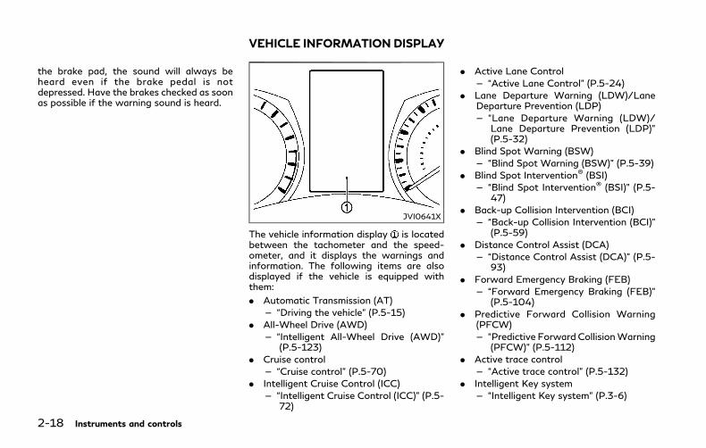
2-18 Instruments and controls
the brake pad, the sound will always beheard even if the brake pedal is notdepressed. Have the brakes checked as soonas possible if the warning sound is heard.
JVI0641X
The vehicle information display is locatedbetween the tachometer and the speed-ometer, and it displays the warnings andinformation. The following items are alsodisplayed if the vehicle is equipped withthem:
. Automatic Transmission (AT)
— “Driving the vehicle” (P.5-15)
. All-Wheel Drive (AWD)
— “Intelligent All-Wheel Drive (AWD)”(P.5-123)
. Cruise control
— “Cruise control” (P.5-70)
. Intelligent Cruise Control (ICC)
— “Intelligent Cruise Control (ICC)” (P.5-72)
. Active Lane Control
— “Active Lane Control” (P.5-24)
. Lane Departure Warning (LDW)/LaneDeparture Prevention (LDP)
— “Lane Departure Warning (LDW)/Lane Departure Prevention (LDP)”(P.5-32)
. Blind Spot Warning (BSW)
— “Blind Spot Warning (BSW)” (P.5-39)
. Blind Spot Intervention® (BSI)
— “Blind Spot Intervention® (BSI)” (P.5-47)
. Back-up Collision Intervention (BCI)
— “Back-up Collision Intervention (BCI)”(P.5-59)
. Distance Control Assist (DCA)
— “Distance Control Assist (DCA)” (P.5-93)
. Forward Emergency Braking (FEB)
— “Forward Emergency Braking (FEB)”(P.5-104)
. Predictive Forward Collision Warning(PFCW)
— “Predictive Forward CollisionWarning(PFCW)” (P.5-112)
. Active trace control
— “Active trace control” (P.5-132)
. Intelligent Key system
— “Intelligent Key system” (P.3-6)
VEHICLE INFORMATION DISPLAY
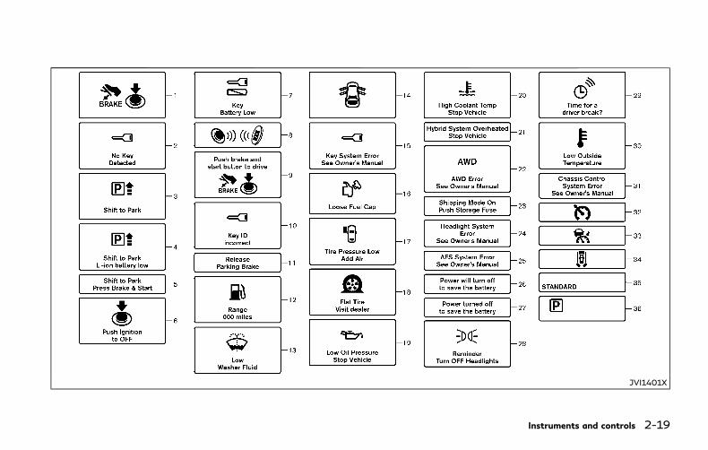
JVI1401X
Instruments and controls 2-19
2-20 Instruments and controls
INDICATORS FOR OPERATION
1. Hybrid system start operationindicatorThis indicator appears when the shift lever isin the P (Park) position.
This indicator means that the INFINITIDirect Response Hybrid® System will startby pushing the ignition switch with the brakepedal depressed. You can start the hybridsystem directly in any position of the ignitionswitch.
2. NO KEY warningThe warning appears when the door isclosed with the Intelligent Key left outsidethe vehicle and the ignition switch in theACC or ON position. Make sure that theIntelligent Key is inside the vehicle.
See “Intelligent Key system” (P.3-6) for moredetails.
3. SHIFT “P” warningThis warning will appear in the followingconditions.
. When the shift lever is in any positionexcept P (Park) and the push buttonignition switch has been placed in theOFF position from the ON position.
. When the shift lever is operatedwhile theREADY to drive indicator light is flashing.
. The driver’s door is opened with the shiftlever in “N”, “D” or “R”.
. When the vehicle cannot be driven be-cause the hybrid system temperature hasbecome too high.
. When the engine stops due to suddendeceleration on a cold winter day.
. If a malfunction occurs in a situationother than those described above andthe engine cannot start automatically.
When this warning appears, place the shiftlever in the P (Park) position.
When the SHIFT “P” warning appears, abuzzer will sound.
This warning will turn off in the followingconditions.
. When the shift lever has been placed inthe P (Park) position.
. When the ignition switch has beenpushed to ON.
4. Shift to Park - Li-ion battery lowwarningThis warning appears when the shift lever isin the “N” position and level of remainingcharge in the Li-ion battery is low.
When this warning appears, place the shiftlever in the P (Park) position.
This will turn off in the following conditions.
. When the shift lever has been placed inthe P (Park) position.
5. Shift to Park - Press brake andstart warningThis warning appears after the hybrid sys-tem was automatically turned off if the levelof remaining charge in the Li-ion battery islow.
When this warning appears, place the shiftlever in the P (Park) position and restart thehybrid system.
6. “PUSH” warningThis warning appears when the shift lever ismoved to the P (Park) position with theignition switch in the ACC position after theSHIFT “P” warning appears.
To push the ignition switch to the OFFposition, perform the following procedure:
. SHIFT “P” warning ? (Move the shiftlever to “P”) ? PUSH warning ? (Pushthe ignition switch ? ignition switchposition is turned to ON) ? PUSHwarning ? (Push the ignition switch ?ignition switch position is turned to OFF)

7. Intelligent Key battery dischargeindicatorThis indicator appears when the IntelligentKey battery is running out of power.
If this indicator appears, replace the batterywith a new one. (See “Intelligent Key batteryreplacement” (P.8-21).)
8. Hybrid system start operation forIntelligent Key system indicatorThis indicator appears when the IntelligentKey battery is running out of power andwhen the Intelligent Key System and vehicleare not communicating normally.
If this indicator appears, touch the ignitionswitch with the Intelligent Key while depres-sing the brake pedal. (See “Intelligent Keybattery discharge” (P.5-13).)
9. Remote engine start indicatorThis indicator appears when the engine hasbeen started using the remote start function.To start the vehicle, depress the brake pedaland place the ignition switch in the ONposition.
For more details, see “Remote engine start”(P.3-19).
10. Key ID Incorrect warningThis warning appears when the ignitionswitch is pushed from the LOCK positionand the Intelligent Key cannot be recognizedby the system. You cannot start the hybridsystem with an unregistered key. Use theregistered Intelligent Key.
See “Intelligent Key” (P.3-2).
11. Parking brake release warningThis warning appears when the vehiclespeed is above 4 MPH (7 km/h) and theparking brake is applied.
12. Low fuel warningThis warning appears when the fuel level inthe tank is getting low. Refuel as soon as it isconvenient, preferably before the fuel gaugereaches the empty (0) position.
There is a small reserve of fuel remaining inthe tank when the fuel gauge reaches theempty (0) position.
13. Low washer fluid warningThis warning appears when the washer tankfluid is at a low level. Add washer fluid asnecessary. (See “Windowwasher fluid” (P.8-13).)
14. Door/trunk open warningThis warning appears if any of the doorsand/or the trunk lid are open or not closedsecurely. The vehicle icon indicates whichdoor or the trunk lid is open on the display.
15. Intelligent Key system warningThis warning appears if there is a malfunc-tion in the Intelligent Key system.
If this warning appears while the hybridsystem is stopped, the hybrid system cannotbe started. If this warning appears while thehybrid system is running, the vehicle can bedriven. However, in these cases, have thesystem checked as soon as possible. It isrecommended you visit an INFINITI retailerfor this service.
16. Loose Fuel Cap warningThis warning appears when the fuel-fillercap is not tightened correctly after thevehicle has been refueled. (See “Fuel-fillercap” (P.3-25).)
17. Tire Pressure Low - Add AirwarningThis warning appears when the low tirepressure warning light in the meter illumi-nates and low tire pressure is detected. Thewarning appears each time the ignitionswitch is placed in the ON position as long
Instruments and controls 2-21

2-22 Instruments and controls
as the low tire pressure warning lightremains illuminated. If this warning appears,stop the vehicle and adjust the pressure tothe recommended COLD tire pressureshown on the Tire and Loading Informationlabel. (See “Low tire pressure warning light”(P.2-12) and “Tire Pressure MonitoringSystem (TPMS)” (P.5-5).)
18. Flat Tire - Visit dealer warningThis warning appears when the low tirepressure warning light in the meter illumi-nates and one or more flat tires are detectedwhile driving. A chime also sounds forapproximately 10 seconds. (See “Low tirepressure warning light” (P.2-12) and “TirePressure Monitoring System (TPMS)” (P.5-5).)
19. Low oil pressure warningThis warning appears if low engine oilpressure is detected. If the warning appearsduring normal driving, pull off the road in asafe area, stop the engine immediately andcall an INFINITI retailer or other authorizedrepair shop.
The low oil pressure warning is not designedto indicate a low oil level. Use the dipstick tocheck the oil level. (See “Engine oil” (P.8-9).)
20. High temperature warningThis warning appears when the enginecoolant temperature is extremely high.
CAUTION
If the high temperature warning appearswhen the ignition switch is in the ONposition, stop the vehicle safely as soonas possible.
If the vehicle is overheated, continuingvehicle operation may seriously damagethe engine. (See “If your vehicle over-heats” (P.6-8) for the immediate actionrequired.)
21. Hybrid system overheat warningThis warning appears when the temperatureof the hybrid system is extremely high. Stopthe vehicle in a safe location as soon aspossible. Avoid quick starting or abruptacceleration. When the warning turns off,the vehicle can be driven.
If the warning appears again soon after itturns off, it is recommended that you havethe vehicle checked by an INFINITI retailer.
WARNING
Do not hold the vehicle in a stoppedposition on an uphill grade by depressingthe accelerator or by slowly creepingforward. This may cause damage to thetransmission or the vehicle may entertraffic causing serious injury or death.Always use the brake pedal when stop-ping on an uphill grade.
CAUTION
. If you continue to drive the vehiclewhile the warning is displayed, thevehicle may become undriveable. Ifthis occurs, place the shift lever in the“P” position and wait for a shortperiod of time with the vehiclestopped until the display goes out.In this case, the warning will bedisplayed alternately with the SHIFT“P” warning. (See “3. SHIFT “P”warning” (P.2-20).)
. Do not drive the vehicle with thewarning on. Doing so could cause ahybrid system malfunction.
22. All-Wheel Drive (AWD) warning(if so equipped)This warning appears when the IntelligentAll-Wheel Drive (AWD) system is not func-tioning properly while the hybrid system isrunning. The displayed message will varydepending on the condition of the AWDsystem malfunction. (See “Intelligent All-Wheel Drive (AWD)” (P.5-123).)
23. Extended storage fuse warningThis warning may appear if the extendedstorage fuse switch is not pushed in(switched on). When this warning appears,push in (switch on) the extended storagefuse switch to turn off the warning. Formore information, see “Extended storagefuse switch” (P.8-21).
24. Headlight warningThis warning appears if the LED headlightsare malfunctioning. It is recommended youhave the system checked by an INFINITIretailer.
25. Adaptive Front lighting System(AFS) warning (if so equipped)This warning appears when the AdaptiveFront lighting System (AFS) is not function-ing properly. It is recommended you have thesystem checked by an INFINITI retailer.
(See “Adaptive Front lighting System (AFS)”(P.2-41).)
26. Power will turn off to save thebattery warningThis warning appears after a period of timeif the shift lever has not moved from the “P”(Park) position with the ignition switch in theACC or ON position.
27. Power turned off to save thebattery warningThis warning appears after the ignitionswitch is automatically turned OFF to savethe 12-volt battery.
28. Light reminder warningThis warning appears when the driver sidedoor is opened with the headlight switch leftON and the ignition switch in the ACC, OFFor LOCK position. Place the headlight switchto “OFF” or “AUTO” position. For additionalinformation, see “Headlight and turn signalswitch” (P.2-36).
29. “TIMER” indicatorThis indicator appearswhen the set “TIMER”indicator activates. You can set the time forup to 6 hours. (See the Infiniti InTouchOwner’s Manual.)
30. Low outside temperaturewarningThis warning appears if the outside tem-perature is below 37°F (3°C). The warningcan be set not to be displayed. (See theInfiniti InTouch Owner’s Manual.)
31. Chassis control warningThis warning appears if Active Lane Control(if so equipped), the active trace controlsystem and/or chassis control are notfunctioning properly. It is recommendedyou have the system checked by an INFINITIretailer. (See “Active Lane Control” (P.5-24),“Active trace control” (P.5-132) and “Chassiscontrol” (P.5-134).)
32. Cruise indicator
Models without Intelligent Cruise Control(ICC) system:
This indicator shows the cruise controlsystem status. The status is shown by thecolor.
See “Cruise control” (P.5-70) for details.
Models with Intelligent Cruise Control (ICC)system:
This indicator shows the conventional (fixedspeed) cruise control mode status. Thestatus is shown by the color.
Instruments and controls 2-23

2-24 Instruments and controls
See “Conventional (fixed speed) cruise con-trol mode” (P.5-89) for details.
33. Intelligent Cruise Control (ICC)system ON indicator (if soequipped)This indicator shows the Intelligent CruiseControl (ICC) system status. The status isshown by the color. (See “Intelligent CruiseControl (ICC)” (P.5-72).)
34. Driver assist system indicatorThis indicator shows the status of thefollowing systems.
. Lane Departure Warning (LDW) (if soequipped)
. Lane Departure Prevention (LDP) (if soequipped)
. Blind Spot Warning (BSW)
. Blind Spot Intervention® (BSI) (if soequipped)
. Distance Control Assist (DCA) (if soequipped)
. Forward Emergency Braking (FEB)
. Predictive Forward Collision Warning(PFCW)
For more details, see “Lane DepartureWarning (LDW)/Lane Departure Prevention(LDP)” (P.5-32), “Blind Spot Warning(BSW)” (P.5-39), “Blind Spot Intervention®
(BSI)” (P.5-47), “Distance Control Assist(DCA)” (P.5-93), “Forward Emergency Brak-ing (FEB)” (P.5-104) and “Predictive For-ward Collision Warning (PFCW)” (P.5-112).
The figure and color of this indicator willchange depending on the conditions of theabove systems. (In each section, the name ofthis indicator is referred to as, “driver assistsystem lane indicator”, “driver assist systemblind spot indicator” or “driver assist systemforward indicator” depending on the sys-tems.)
35. INFINITI Drive Mode SelectorindicatorWhen a driving mode is selected using theINFINITI Drive Mode Selector, the selectedmode indicator is displayed.
. PERSONAL
. SPORT
. STANDARD
. ECO
. SNOW
(See “INFINITI Drive Mode Selector” (P.5-21).)
36. Automatic Transmission (AT)position indicatorThis indicator shows the automatic shiftposition.
In the manual shift mode, when the trans-mission does not shift to the selected geardue to a transmission protection mode, theAT position indicator will blink and a chimewill sound.
See “Automatic transmission” (P.5-15) forfurther details.
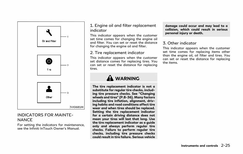
JVI0681M
INDICATORS FOR MAINTE-NANCEFor setting the indicators for maintenance,see the Infiniti InTouch Owner’s Manual.
1. Engine oil and filter replacementindicatorThis indicator appears when the customerset time comes for changing the engine oiland filter. You can set or reset the distancefor changing the engine oil and filter.
2. Tire replacement indicatorThis indicator appears when the customerset distance comes for replacing tires. Youcan set or reset the distance for replacingtires.
WARNING
The tire replacement indicator is not asubstitute for regular tire checks, includ-ing tire pressure checks. See “Changingwheels and tires” (P.8-36).Many factorsincluding tire inflation, alignment, driv-ing habits and road conditions affect tirewear and when tires should be replaced.Setting the tire replacement indicatorfor a certain driving distance does notmean your tires will last that long. Usethe tire replacement indicator as a guideonly and always perform regular tirechecks. Failure to perform regular tirechecks, including tire pressure checkscould result in tire failure. Serious vehicle
damage could occur and may lead to acollision, which could result in seriouspersonal injury or death.
3. Other indicatorThis indicator appears when the customerset time comes for replacing items otherthan the engine oil, oil filter and tires. Youcan set or reset the distance for replacingthe items.
Instruments and controls 2-25

2-26 Instruments and controls
JVI1706X
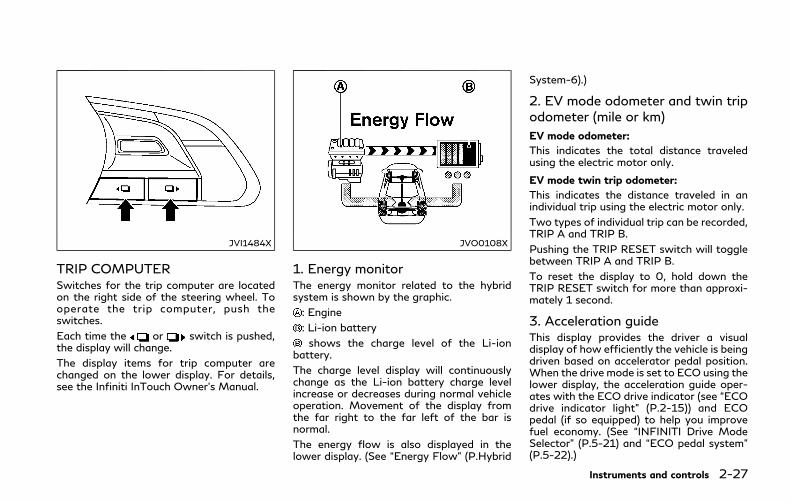
JVI1484X
TRIP COMPUTERSwitches for the trip computer are locatedon the right side of the steering wheel. Tooperate the trip computer, push theswitches.
Each time the or switch is pushed,the display will change.
The display items for trip computer arechanged on the lower display. For details,see the Infiniti InTouch Owner’s Manual.
JVO0108X
1. Energy monitorThe energy monitor related to the hybridsystem is shown by the graphic.
: Engine
: Li-ion battery
shows the charge level of the Li-ionbattery.
The charge level display will continuouslychange as the Li-ion battery charge levelincrease or decreases during normal vehicleoperation. Movement of the display fromthe far right to the far left of the bar isnormal.
The energy flow is also displayed in thelower display. (See “Energy Flow” (P.Hybrid
System-6).)
2. EV mode odometer and twin tripodometer (mile or km)
EV mode odometer:
This indicates the total distance traveledusing the electric motor only.
EV mode twin trip odometer:
This indicates the distance traveled in anindividual trip using the electric motor only.
Two types of individual trip can be recorded,TRIP A and TRIP B.
Pushing the TRIP RESET switch will togglebetween TRIP A and TRIP B.
To reset the display to 0, hold down theTRIP RESET switch for more than approxi-mately 1 second.
3. Acceleration guideThis display provides the driver a visualdisplay of how efficiently the vehicle is beingdriven based on accelerator pedal position.When the drive mode is set to ECO using thelower display, the acceleration guide oper-ates with the ECO drive indicator (see “ECOdrive indicator light” (P.2-15)) and ECOpedal (if so equipped) to help you improvefuel economy. (See “INFINITI Drive ModeSelector” (P.5-21) and “ECO pedal system”(P.5-22).)
Instruments and controls 2-27

2-28 Instruments and controls
JVI0711X
: Accelerator pedal position indicator
: Power range
: Economy range
JVI0712X
The above examples of the accelerationguide indicate the following conditions.
1. The vehicle is being driven economicallywhen the vehicle is driven with theaccelerator pedal position in the econo-my range.
2. The vehicle is being driven less econom-ically when the vehicle is driven with theaccelerator pedal position in the powerrange.
This will not be displayed when IntelligentCruise Control (ICC) system (if so equipped)or cruse control system (if so equipped) isoperating.
4. Current fuel consumption andaverage fuel consumption (MPG, l(liter)/100 km or km/l)
Current fuel consumption:
The current fuel consumption mode showsthe current fuel consumption.
Average fuel consumption:
The average fuel consumption mode showsthe average fuel consumption since the lastreset. Resetting is done by pushing theor switch for longer than 1 second.
The average fuel consumption is also reseton the lower display. See the Infiniti InTouchOwner’s Manual.
The display is updated every 30 seconds. Atabout the first 1/3 mile (500 m) after areset, the display shows “——”.
5. Vehicle speed (MPH or km/h)The vehicle speed mode shows the currentvehicle speed and the average vehicle speedsince the last reset.
Average vehicle speed:
Resetting is done by pushing the orswitch for longer than 1 second.
The average vehicle speed display is updatedevery 30 seconds. The first 30 seconds aftera reset, the display shows “——”.
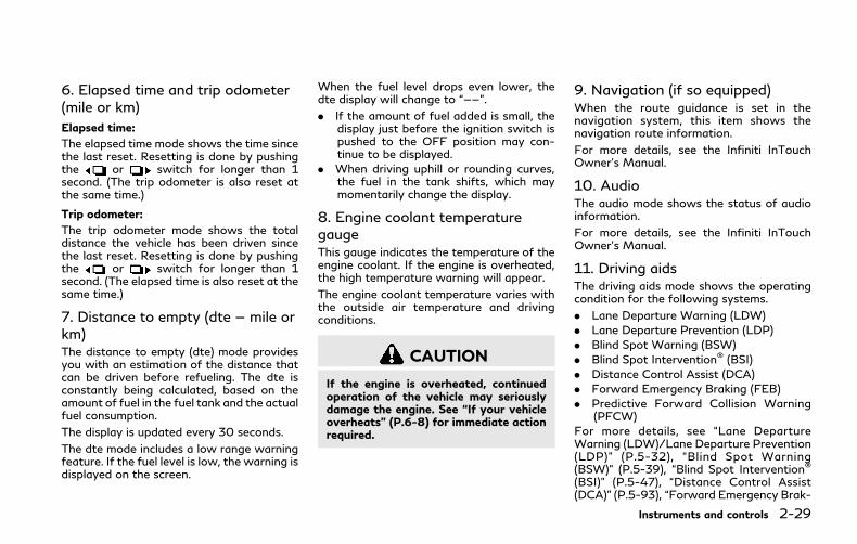
6. Elapsed time and trip odometer(mile or km)
Elapsed time:
The elapsed time mode shows the time sincethe last reset. Resetting is done by pushingthe or switch for longer than 1second. (The trip odometer is also reset atthe same time.)
Trip odometer:
The trip odometer mode shows the totaldistance the vehicle has been driven sincethe last reset. Resetting is done by pushingthe or switch for longer than 1second. (The elapsed time is also reset at thesame time.)
7. Distance to empty (dte — mile orkm)The distance to empty (dte) mode providesyou with an estimation of the distance thatcan be driven before refueling. The dte isconstantly being calculated, based on theamount of fuel in the fuel tank and the actualfuel consumption.
The display is updated every 30 seconds.
The dte mode includes a low range warningfeature. If the fuel level is low, the warning isdisplayed on the screen.
When the fuel level drops even lower, thedte display will change to “——”.
. If the amount of fuel added is small, thedisplay just before the ignition switch ispushed to the OFF position may con-tinue to be displayed.
. When driving uphill or rounding curves,the fuel in the tank shifts, which maymomentarily change the display.
8. Engine coolant temperaturegaugeThis gauge indicates the temperature of theengine coolant. If the engine is overheated,the high temperature warning will appear.
The engine coolant temperature varies withthe outside air temperature and drivingconditions.
CAUTION
If the engine is overheated, continuedoperation of the vehicle may seriouslydamage the engine. See “If your vehicleoverheats” (P.6-8) for immediate actionrequired.
9. Navigation (if so equipped)When the route guidance is set in thenavigation system, this item shows thenavigation route information.
For more details, see the Infiniti InTouchOwner’s Manual.
10. AudioThe audio mode shows the status of audioinformation.
For more details, see the Infiniti InTouchOwner’s Manual.
11. Driving aidsThe driving aids mode shows the operatingcondition for the following systems.
. Lane Departure Warning (LDW)
. Lane Departure Prevention (LDP)
. Blind Spot Warning (BSW)
. Blind Spot Intervention® (BSI)
. Distance Control Assist (DCA)
. Forward Emergency Braking (FEB)
. Predictive Forward Collision Warning(PFCW)
For more details, see “Lane DepartureWarning (LDW)/Lane Departure Prevention(LDP)” (P.5-32), “Blind Spot Warning(BSW)” (P.5-39), “Blind Spot Intervention®
(BSI)” (P.5-47), “Distance Control Assist(DCA)” (P.5-93), “Forward Emergency Brak-
Instruments and controls 2-29
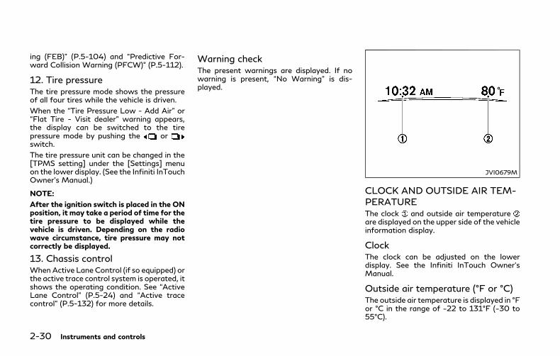
2-30 Instruments and controls
ing (FEB)” (P.5-104) and “Predictive For-ward Collision Warning (PFCW)” (P.5-112).
12. Tire pressureThe tire pressure mode shows the pressureof all four tires while the vehicle is driven.
When the “Tire Pressure Low - Add Air” or“Flat Tire - Visit dealer” warning appears,the display can be switched to the tirepressure mode by pushing the orswitch.
The tire pressure unit can be changed in the[TPMS setting] under the [Settings] menuon the lower display. (See the Infiniti InTouchOwner’s Manual.)
NOTE:
After the ignition switch is placed in the ONposition, it may take a period of time for thetire pressure to be displayed while thevehicle is driven. Depending on the radiowave circumstance, tire pressure may notcorrectly be displayed.
13. Chassis controlWhen Active Lane Control (if so equipped) orthe active trace control system is operated, itshows the operating condition. See “ActiveLane Control” (P.5-24) and “Active tracecontrol” (P.5-132) for more details.
Warning checkThe present warnings are displayed. If nowarning is present, “No Warning” is dis-played.
JVI0679M
CLOCK AND OUTSIDE AIR TEM-PERATUREThe clock and outside air temperatureare displayed on the upper side of the vehicleinformation display.
ClockThe clock can be adjusted on the lowerdisplay. See the Infiniti InTouch Owner’sManual.
Outside air temperature (°F or °C)The outside air temperature is displayed in °For °C in the range of −22 to 131°F (−30 to55°C).

The outside temperature sensor is located infront of the radiator. The sensor may beaffected by road or engine heat, winddirections and other driving conditions. Thedisplay may differ from the actual outsidetemperature or the temperature displayedon various signs or billboards.
SIC2132
Your vehicle has two types of securitysystems, as follows:
. Vehicle security system
. INFINITI Vehicle Immobilizer System
The security condition will be shown by thesecurity indicator light.
VEHICLE SECURITY SYSTEMThe vehicle security system provides visualand audio alarm signals if someone opensthe doors, hood, or trunk lid when thesystem is armed. It is not, however, a motiondetection type system that activates when avehicle is moved or when a vibration occurs.
The system helps deter vehicle theft butcannot prevent it, nor can it prevent the
theft of interior or exterior vehicle compo-nents in all situations. Always secure yourvehicle even if parking for a brief period.Never leave your Intelligent Key(s) in thevehicle, and always lock it when unattended.Be aware of your surroundings, and park insecure, well-lit areas whenever possible.
Many devices offering additional protection,such as component locks, identificationmarkers, and tracking systems, are availableat auto supply stores and specialty shops.Your INFINITI retailer may also offer suchequipment. Check with your insurance com-pany to see if you may be eligible fordiscounts for various theft protection fea-tures.
Instruments and controls 2-31
SECURITY SYSTEMS

2-32 Instruments and controls
SIC2045
How to arm the vehicle securitysystem1. Close all windows.
The system can be armed even if thewindows are open.
2. Push the ignition switch to the OFFposition.
3. Remove the Intelligent Key from thevehicle.
4. Close all doors, hood and trunk. Lock alldoors. The doors can be locked with theIntelligent Key, door handle requestswitch, power door lock switch or me-chanical key.
5. Confirm that the security indicator lightcomes on. The security indicator lightstays on for about 30 seconds. Thevehicle security system is now pre-armed. After about 30 seconds thevehicle security system automaticallyshifts into the armed phase. The securitylight begins to flash once every approxi-mately 3 seconds. If, during this 30-second pre-arm time period, the door isunlocked, or the ignition switch is pushedto ACC or ON, the system will not arm.
Even when the driver and/or passengersare in the vehicle, the system will activatewith all doors, hood, and trunk lid lockedwith the ignition switch in the LOCKposition. When pushing the ignition switchto the ACC or ON position, the system willbe released.
Vehicle security system activationThe vehicle security system will give thefollowing alarm:
. The headlights blink and the horn soundsintermittently.
. The alarm automatically turns off afterapproximately 1 minute. However, thealarm reactivates if the vehicle is tam-pered with again.
The alarm is activated by:
. Unlocking the door or opening the trunklid without using the button on theIntelligent Key, the door handle requestswitch, one touch unlock sensor or themechanical key. (Even if the door isopened by releasing the door inside lockknob, the alarm will activate.)
. Opening the hood.
How to stop an activated alarmThe alarm will stop by unlocking a door bypushing the UNLOCK button on the Intelli-gent Key, pushing the door handle requestswitch, touching the one touch unlocksensor or using the mechanical key. Thealarm will not stop if the ignition switch isplaced in the ACC or ON position.
If the system does not operate as describedabove, it is recommended you have itchecked by an INFINITI retailer.
INFINITI VEHICLE IMMOBILIZERSYSTEMThe INFINITI Vehicle Immobilizer Systemwill not allow the INFINITI Direct ResponseHybrid® System to start without the use ofthe registered Intelligent Key. Never leavethese keys in the vehicle.
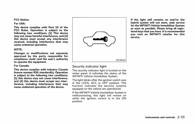
FCC Notice:
For USA:
This device complies with Part 15 of theFCC Rules. Operation is subject to thefollowing two conditions: (1) This devicemay not cause harmful interference, and (2)this device must accept any interferencereceived, including interference that maycause undesired operation.
NOTE:
Changes or modifications not expresslyapproved by the party responsible forcompliance could void the user’s authorityto operate the equipment.
For Canada:
This device complies with Industry Canadalicence-exempt RSS standard(s). Operationis subject to the following two conditions:(1) this device may not cause interference,and (2) this device must accept any inter-ference, including interference that maycause undesired operation of the device.
SIC2045
Security indicator lightThe security indicator light is located on themeter panel. It indicates the status of theINFINITI Vehicle Immobilizer System.
The light blinks after the ignition switch wasin the LOCK, ACC or OFF position. Thisfunction indicates the security systemsequipped on the vehicle are operational.
If the INFINITI Vehicle Immobilizer System ismalfunctioning, this light will remain onwhile the ignition switch is in the ONposition.
If the light still remains on and/or thehybrid system will not start, seek servicefor the INFINITI Vehicle Immobilizer Systemas soon as possible. Please bring all regis-tered keys that you have. It is recommendedyou visit an INFINITI retailer for thisservice.
Instruments and controls 2-33
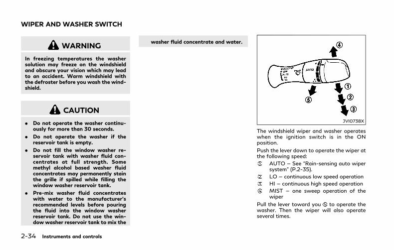
2-34 Instruments and controls
WARNING
In freezing temperatures the washersolution may freeze on the windshieldand obscure your vision which may leadto an accident. Warm windshield withthe defroster before you wash the wind-shield.
CAUTION
. Do not operate the washer continu-ously for more than 30 seconds.
. Do not operate the washer if thereservoir tank is empty.
. Do not fill the window washer re-servoir tank with washer fluid con-centrates at full strength. Somemethyl alcohol based washer fluidconcentrates may permanently stainthe grille if spilled while filling thewindow washer reservoir tank.
. Pre-mix washer fluid concentrateswith water to the manufacturer’srecommended levels before pouringthe fluid into the window washerreservoir tank. Do not use the win-dow washer reservoir tank to mix the
washer fluid concentrate and water.
JVI0738X
The windshield wiper and washer operateswhen the ignition switch is in the ONposition.
Push the lever down to operate the wiper atthe following speed:
AUTO — See “Rain-sensing auto wipersystem” (P.2-35).
LO — continuous low speed operation
HI — continuous high speed operation
MIST — one sweep operation of thewiper
Pull the lever toward you to operate thewasher. Then the wiper will also operateseveral times.
WIPER AND WASHER SWITCH

Pulling up the wiper arm:
The wiper arm should be in the up positionwhen replacing the wiper.
To pull up the wiper arm, push up twicewhen the ignition switch is in the OFFposition within 1 minute. The wiper opera-tion stops in mid-operation and the wiperarm can be pulled up.
The shift lever should be in the P (Park)position.
To return the wiper arm, place the wiper armin the down position and operate the wiperswitch once.
CAUTION
Do not operate the windshield wiperwhile the wiper arm is pulled up. Thewiper arm may be damaged.
Wiper drip wipe system:
The wiper will also operate once about 3seconds after the washer and wiper areoperated. This operation is to wipe washerfluid that has dripped on the windshield.
JVI0739X
RAIN-SENSING AUTO WIPERSYSTEMThe rain-sensing auto wiper system canautomatically turn on the wipers and adjustthe wiper speed depending on the rainfalland the vehicle speed by using the rainsensor located on the upper part of thewindshield.
To set the rain-sensing auto wiper system,push the lever down to the AUTO position. The wiper will sweep once while the
ignition switch is in the ON position.
The rain sensor sensitivity level can beadjusted by turning the knob toward(High) or toward (Low).
. High — High sensitive operation
. Low — Low sensitive operation
To turn the rain-sensing auto wiper systemoff, push up the lever to the OFF position, orpull down the lever to the LO or HI position.
CAUTION
Do not touch the rain sensor and aroundit when the wiper switch is in the AUTOposition and the ignition switch is in theON position. The wipers may operateunexpectedly and cause an injury or maydamage a wiper.
. The rain-sensing auto wipers are in-tended for use during rain. If the switchis left in the AUTO position, the wipersmay operate unexpectedly when dirt,fingerprints, oil film or insects are stuckon or around the sensor. The wipers mayalso operate when exhaust gas ormoisture affect the rain sensor.
. The rain-sensing auto wipers may notoperate if rain does not hit the rainsensor even if it is raining.
. When the windshield glass is coatedwith water repellent, the speed of therain-sensing auto wipers may be highereven though the amount of the rainfall issmall.
Instruments and controls 2-35

2-36 Instruments and controls
. Be sure to turn off the rain-sensing autowiper system when you use a car wash.
. Using genuine wiper blades is recom-mended for proper operation of therain-sensing auto wiper system. (See“Windshield wiper blades” (P.8-17) forwiper blade replacement.)
JVI1441X
To defog/defrost the rear window glass andoutside mirrors, start the INFINITI DirectResponse Hybrid® System and push theswitch on. The indicator light will comeon. Push the switch again to turn thedefroster off.
It will automatically turn off in approxi-mately 15 minutes.
CAUTION
When cleaning the inner side of the rearwindow, be careful not to scratch ordamage the rear window defroster.
SIC3267
HEADLIGHT SWITCH
LightingTurn the switch to the position:
The front parking, side marker, tail andlicense plate lights will come on.
Turn the switch to the position:
Headlights will come on and all theother lights remain on.
REAR WINDOW AND OUTSIDEMIRROR DEFROSTER SWITCH HEADLIGHT AND TURN SIGNAL SWITCH

SIC3268
Autolight systemThe autolight system allows the headlightsto be set so they turn on and off auto-matically.
To set the autolight system:
1. Make sure the headlight switch is in theAUTO position .
2. Push the ignition switch to the ONposition.
3. The autolight system automatically turnsthe headlights on and off.
To turn the autolight system off, turn theswitch to the OFF, or position.
The autolight system can turn on the head-
lights automatically when it is dark and turnoff the headlights when it is light.
The headlights will turn on automatically attwilight or in rainy weather (when thewindshield wiper is operated continuously).
If the ignition switch is pushed to the OFFposition and one of the doors is opened andthis condition is continued, the headlightsremain on for 5 minutes.
Automatic headlights off delay:
You can keep the headlights on for up to 180seconds after you push the ignition switch toOFF and open any door then close all thedoors.
You can adjust the period of the automaticheadlights off delay from 0 seconds (OFF)to 180 seconds. The factory default settingis 45 seconds.
For automatic headlights off delay setting,see the Infiniti InTouch Owner’s Manual.
SIC3784
Be sure not to put anything on top of thephoto sensor located on the top of theinstrument panel. The photo sensor controlsthe autolight; if it is covered, the photosensor reacts as if it is dark and the head-lights will illuminate.
Instruments and controls 2-37
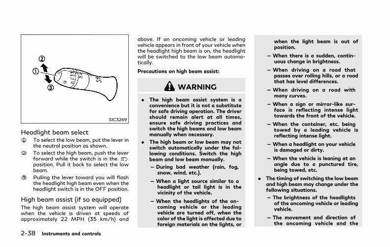
2-38 Instruments and controls
SIC3269
Headlight beam selectTo select the low beam, put the lever inthe neutral position as shown.
To select the high beam, push the leverforward while the switch is in theposition. Pull it back to select the lowbeam.
Pulling the lever toward you will flashthe headlight high beam even when theheadlight switch is in the OFF position.
High beam assist (if so equipped)The high beam assist system will operatewhen the vehicle is driven at speeds ofapproximately 22 MPH (35 km/h) and
above. If an oncoming vehicle or leadingvehicle appears in front of your vehicle whenthe headlight high beam is on, the headlightwill be switched to the low beam automa-tically.
Precautions on high beam assist:
WARNING
. The high beam assist system is aconvenience but it is not a substitutefor safe driving operation. The drivershould remain alert at all times,ensure safe driving practices andswitch the high beams and low beammanually when necessary.
. The high beam or low beam may notswitch automatically under the fol-lowing conditions. Switch the highbeam and low beam manually.
— During bad weather (rain, fog,snow, wind, etc.).
— When a light source similar to aheadlight or tail light is in thevicinity of the vehicle.
— When the headlights of the on-coming vehicle or the leadingvehicle are turned off, when thecolor of the light is affected due toforeign materials on the lights, or
when the light beam is out ofposition.
— When there is a sudden, contin-uous change in brightness.
— When driving on a road thatpasses over rolling hills, or a roadthat has level differences.
— When driving on a road withmany curves.
— When a sign or mirror-like sur-face is reflecting intense lighttowards the front of the vehicle.
— When the container, etc. beingtowed by a leading vehicle isreflecting intense light.
— When a headlight on your vehicleis damaged or dirty.
— When the vehicle is leaning at anangle due to a punctured tire,being towed, etc.
. The timing of switching the low beamand high beam may change under thefollowing situations.
— The brightness of the headlightsof the oncoming vehicle or leadingvehicle.
— The movement and direction ofthe oncoming vehicle and the
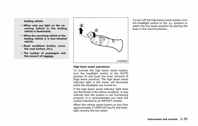
leading vehicle.
— When only one light on the on-coming vehicle or the leadingvehicle is illuminated.
— When the oncoming vehicle or theleading vehicle is a two-wheeledvehicle.
— Road conditions (incline, curve,the road surface, etc.).
— The number of passengers andthe amount of luggage.
JVI0686X
High beam assist operations:
To activate the high beam assist system,turn the headlight switch to the AUTOposition and push the lever forward(high beam position). The high beam assistindicator light in the meter will illuminatewhile the headlights are turned on.
If the high beam assist indicator light doesnot illuminate in the above condition, it mayindicate that the system is not functioningproperly. It is recommended you have thesystem checked by an INFINITI retailer.
When the vehicle speed lowers to less thanapproximately 17MPH (27 km/h), the head-light remains the low beam.
To turn off the high beam assist system, turnthe headlight switch to the position orselect the low beam position by placing thelever in the neutral position.
Instruments and controls 2-39
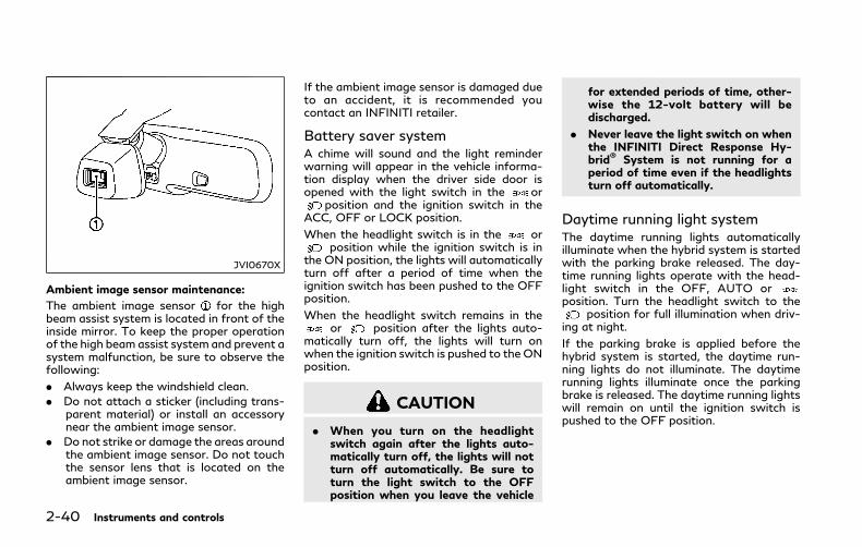
2-40 Instruments and controls
JVI0670X
Ambient image sensor maintenance:
The ambient image sensor for the highbeam assist system is located in front of theinside mirror. To keep the proper operationof the high beam assist system and prevent asystem malfunction, be sure to observe thefollowing:
. Always keep the windshield clean.
. Do not attach a sticker (including trans-parent material) or install an accessorynear the ambient image sensor.
. Do not strike or damage the areas aroundthe ambient image sensor. Do not touchthe sensor lens that is located on theambient image sensor.
If the ambient image sensor is damaged dueto an accident, it is recommended youcontact an INFINITI retailer.
Battery saver systemA chime will sound and the light reminderwarning will appear in the vehicle informa-tion display when the driver side door isopened with the light switch in the or
position and the ignition switch in theACC, OFF or LOCK position.
When the headlight switch is in the orposition while the ignition switch is in
the ON position, the lights will automaticallyturn off after a period of time when theignition switch has been pushed to the OFFposition.
When the headlight switch remains in theor position after the lights auto-
matically turn off, the lights will turn onwhen the ignition switch is pushed to the ONposition.
CAUTION
. When you turn on the headlightswitch again after the lights auto-matically turn off, the lights will notturn off automatically. Be sure toturn the light switch to the OFFposition when you leave the vehicle
for extended periods of time, other-wise the 12-volt battery will bedischarged.
. Never leave the light switch on whenthe INFINITI Direct Response Hy-brid® System is not running for aperiod of time even if the headlightsturn off automatically.
Daytime running light systemThe daytime running lights automaticallyilluminate when the hybrid system is startedwith the parking brake released. The day-time running lights operate with the head-light switch in the OFF, AUTO orposition. Turn the headlight switch to the
position for full illumination when driv-ing at night.
If the parking brake is applied before thehybrid system is started, the daytime run-ning lights do not illuminate. The daytimerunning lights illuminate once the parkingbrake is released. The daytime running lightswill remain on until the ignition switch ispushed to the OFF position.

WARNING
When the daytime running light systemis active, tail lights on your vehicle arenot on. It is necessary at dusk to turn onyour headlights. Failure to do so couldcause an accident injuring yourself andothers.
Adaptive Front lighting System(AFS) (if so equipped)The Adaptive Front lighting System (AFS)will automatically adjust the headlights (lowbeam) toward the turning direction toimprove the driver’s view. When the head-light switch is ON and the driver operatesthe steering wheel in a turn, the AFS systemwill be activated.
The AFS will operate:
. when the headlight switch is ON.
. when the shift lever is in any positionother than P (Park) or R (Reverse).
. when the vehicle is driven at above 3MPH (5 km/h) for the left-side head-light. Note that the right-side low beamheadlight will swivel but the left-sideheadlight will not swivel when the vehicleis below 3 MPH (5 km/h) and thesteering wheel is turned.
AFSwill also adjust the headlight to a properaxis automatically, depending on the numberof occupants in the vehicle, the load thevehicle is carrying and the road conditions.
If the AFS warning appears in the vehicleinformation display after the ignition switchhas been placed in the ON position, this mayindicate that the AFS is not functioningproperly. Have the system checked. It isrecommended you visit an INFINITI retailerfor this service. When the hybrid system isstarted, the headlights will vibrate to checkthe system condition. This is not a malfunc-tion.
JVI0644X
JVI0937X
Instruments and controls 2-41
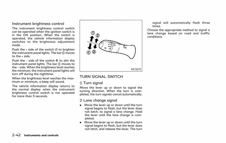
2-42 Instruments and controls
Instrument brightness controlThe instrument brightness control switchcan be operated when the ignition switch isin the ON position. When the switch isoperated, the vehicle information displayswitches to the brightness adjustmentmode.
Push the + side of the switch to brightenthe instrument panel lights. The bar movesto the + side.
Push the - side of the switch to dim theinstrument panel lights. The bar moves tothe − side. When the brightness level reachesthe minimum, the instrument panel lights willturn off during the nighttime.
When the brightness level reaches the max-imum or minimum, a beep will sound.
The vehicle information display returns tothe normal display when the instrumentbrightness control switch is not operatedfor more than 5 seconds.
SIC3271
TURN SIGNAL SWITCH
Turn signalMove the lever up or down to signal theturning direction. When the turn is com-pleted, the turn signals cancel automatically.
Lane change signal. Move the lever up or down until the turn
signal begins to flash, but the lever doesnot latch, to signal a lane change. Holdthe lever until the lane change is com-pleted.
. Move the lever up or down until the turnsignal begins to flash, but the lever doesnot latch, and release the lever. The turn
signal will automatically flash threetimes.
Choose the appropriate method to signal alane change based on road and trafficconditions.
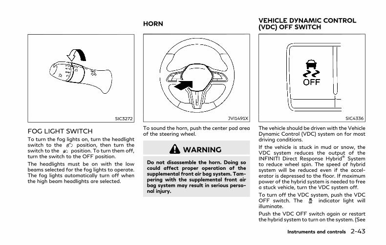
SIC3272
FOG LIGHT SWITCHTo turn the fog lights on, turn the headlightswitch to the position, then turn theswitch to the position. To turn them off,turn the switch to the OFF position.
The headlights must be on with the lowbeams selected for the fog lights to operate.The fog lights automatically turn off whenthe high beam headlights are selected.
JVI1491X
To sound the horn, push the center pad areaof the steering wheel.
WARNING
Do not disassemble the horn. Doing socould affect proper operation of thesupplemental front air bag system. Tam-pering with the supplemental front airbag system may result in serious perso-nal injury.
SIC4336
The vehicle should be driven with the VehicleDynamic Control (VDC) system on for mostdriving conditions.
If the vehicle is stuck in mud or snow, theVDC system reduces the output of theINFINITI Direct Response Hybrid® Systemto reduce wheel spin. The speed of hybridsystem will be reduced even if the accel-erator is depressed to the floor. If maximumpower of the hybrid system is needed to freea stuck vehicle, turn the VDC system off.
To turn off the VDC system, push the VDCOFF switch. The indicator light willilluminate.
Push the VDC OFF switch again or restartthe hybrid system to turn on the system. (See
Instruments and controls 2-43
HORN VEHICLE DYNAMIC CONTROL(VDC) OFF SWITCH

2-44 Instruments and controls
“Vehicle Dynamic Control (VDC) system”(P.5-130).) WARNING
Do not use or allow occupants to use theseat heater if you or the occupantscannot monitor elevated seat tempera-tures or have an inability to feel pain inthose body parts in contact with theseat. Use of the seat heater by suchpeople could result in serious injury.
CAUTION
. The 12-volt battery could run down ifthe seat heater is operated while theINFINITI Direct Response Hybrid®
System is not running.
. Do not use the seat heater forextended periods or when no one isusing the seat.
. Do not put anything on the seatwhich insulates heat, such as a blan-ket, cushion, seat cover, etc. Other-w i se , the seat may becomeoverheated.
. Do not place anything hard or heavyon the seat or pierce it with a pin orsimilar object. This may result indamage to the heater.
. Any liquid spilled on the heated seatshould be removed immediately witha dry cloth.
. When cleaning the seat, never usegasoline, thinner, or any similar ma-terials.
. If any malfunctions are found or theheated seat does not operate, turnthe switch off and have the systemchecked. It is recommended you visitan INFINITI retailer for this service.
HEATED SEATS

JVR0505X
The front seats can be warmed by built-inheaters. The heating system of driver’s seatand front passenger seat can be operatedindependently.
OPERATION WITH SWITCH1. Start the hybrid system.
2. Push the switch on the instrument panel.. Each time the switch is pushed, the
seat heating mode will change in thefollowing order.
AUTO ? High ? Mid? Low ? OFF. The indicator light on the switch will
illuminate when the heater is on.
When the vehicle’s interior is warmed, orbefore you leave the vehicle, be sure to turn
off the seat heater.
OPERATION WITH TOUCHSCREENPush the CLIMATE button and touch [ ]or [ ] on the lower display. Select an itemfrom [AUTO], [High], [Mid], [Low] or [OFF].
AUTO MODE SETTINGWhen in the AUTO mode, the heater willturn on or off automatically according to theconditions such as the temperature insidethe vehicle compartment. Depending on theconditions, the heater will not turn on even ifAUTO is selected. The settings for the AUTOmode can be changed. For details, see theInfiniti InTouch Owner’s Manual.
WARNING
Do not use or allow occupants to comeinto contact with the heated steeringwheel if you or the occupants cannotmonitor elevated steering wheel tem-peratures or have an inability to feel painin those body parts in contact. Use of theheated steering wheel by such peoplecould result in serious injuries.
CAUTION
. The 12-volt battery could run down ifthe steering wheel heater is operatedwhile the INFINITI Direct ResponseHybrid® System is not running.
. Do not use the steering wheel heaterfor extended periods of time as it maycause burns and overheating.
. Any liquid spilled on the steeringwheel should be removed immedi-ately with a dry cloth.
. When cleaning the steering wheel,never use gasoline, thinner, or anysimilar materials.
. If any malfunctions are found or thesteering wheel heater does not oper-
Instruments and controls 2-45
HEATED STEERING WHEEL
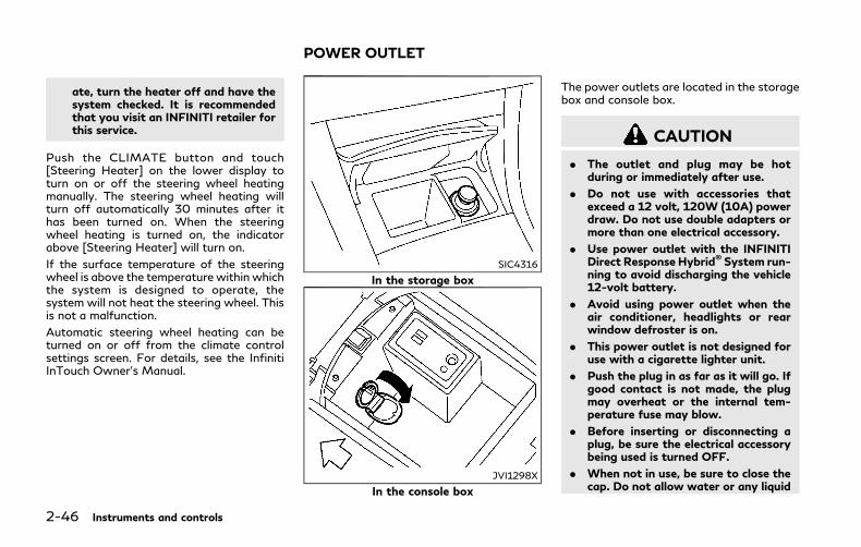
2-46 Instruments and controls
ate, turn the heater off and have thesystem checked. It is recommendedthat you visit an INFINITI retailer forthis service.
Push the CLIMATE button and touch[Steering Heater] on the lower display toturn on or off the steering wheel heatingmanually. The steering wheel heating willturn off automatically 30 minutes after ithas been turned on. When the steeringwheel heating is turned on, the indicatorabove [Steering Heater] will turn on.
If the surface temperature of the steeringwheel is above the temperature within whichthe system is designed to operate, thesystem will not heat the steering wheel. Thisis not a malfunction.
Automatic steering wheel heating can beturned on or off from the climate controlsettings screen. For details, see the InfinitiInTouch Owner’s Manual.
SIC4316
In the storage box
JVI1298X
In the console box
The power outlets are located in the storagebox and console box.
CAUTION
. The outlet and plug may be hotduring or immediately after use.
. Do not use with accessories thatexceed a 12 volt, 120W (10A) powerdraw. Do not use double adapters ormore than one electrical accessory.
. Use power outlet with the INFINITIDirect Response Hybrid® System run-ning to avoid discharging the vehicle12-volt battery.
. Avoid using power outlet when theair conditioner, headlights or rearwindow defroster is on.
. This power outlet is not designed foruse with a cigarette lighter unit.
. Push the plug in as far as it will go. Ifgood contact is not made, the plugmay overheat or the internal tem-perature fuse may blow.
. Before inserting or disconnecting aplug, be sure the electrical accessorybeing used is turned OFF.
. When not in use, be sure to close thecap. Do not allow water or any liquid
POWER OUTLET

to contact the outlet.
SIC2570
REARTo open the ashtray lid, pull .
To empty the ashtray, push down , and pullout.
CUP HOLDERS
CAUTION
. Avoid abrupt starting and brakingwhen the cup holder is being used toprevent spilling the drink. If the liquidis hot, it can scald you or yourpassenger.
. Use only soft cups in the cup holder.Hard objects can injure you in anaccident.
Instruments and controls 2-47
ASHTRAY STORAGE

2-48 Instruments and controls
JVI0649X
Front
JVI0650X
Rear
Open the lid of the rear armrest to use thecup holder.
JVI0715X
SOFT BOTTLE HOLDER
CAUTION
. Do not use bottle holder for any otherobjects that could be thrown about inthe vehicle and possibly injure peopleduring sudden braking or an accident.
. Do not use bottle holder for openliquid containers.

JVI0651X
SUNGLASSES HOLDER
WARNING
Keep the sunglasses holder closed whiledriving to avoid obstructing the driver’sview and to help prevent an accident.
To open the sunglasses holder, push it.
CAUTION
. Do not use for anything other thanglasses.
. Do not leave glasses in the sunglassesholder while parking in direct sun-light. The heat may damage theglasses.
JVI0763X
GLOVE BOX
WARNING
Keep glove box lid closedwhile driving tohelp prevent injury in an accident or asudden stop.
To open the glove box, pull the handle .
To close, push the lid in until the lock latches.
To lock /unlock the glove box, use themechanical key. For the mechanical keyusage, see “Keys” (P.3-2).
Instruments and controls 2-49

2-50 Instruments and controls
JVI0653X
CONSOLE BOXTo open the console box, push up the knoband pull up the lid.
To close, push the lid down until latched.
The console box light illuminates when theheadlight switch is in the position.
SIC4348
CARD HOLDERThe card holder is located on the driver’s orpassenger’s sun visor.
To use the card holder, slide the card in thecard holder.
JVI0664X
STORAGE BOXTo open, push the storage box lid.
Do not place valuable items in the storagebox.
Do not use the storage box as an ashtray.

SIC3248
COAT HOOKSThe coat hooks are equipped beside the rearpersonal lights.
CAUTION
Do not place items which are more than2 lb (1 kg) on the hook.
SIC4350
TRUNK HOOKS
WARNING
. Always make sure that the cargo isproperly secured. Use the suitableropes and hooks.
. Unsecured cargo can become danger-ous in an accident or sudden stop.
CAUTION
Do not apply a total load of more than22 lb (10 kg) to a single hook.
Instruments and controls 2-51

2-52 Instruments and controls
POWER WINDOWS
WARNING
. Make sure that all passengers havetheir hands, etc. inside the vehiclewhile it is in motion and beforeclosing the windows. Use the windowlock switch to prevent unexpecteduse of the power windows.
. To help avoid risk of injury or deaththrough unintended operation of thevehicle and or its systems, includingentrapment in windows or inadver-tent door lock activation, do notleave children, people who requirethe assistance of others or petsunattended in your vehicle. Addition-ally, the temperature inside a closedvehicle on a warm day can quicklybecome high enough to cause a sig-nificant risk of injury or death topeople and pets.
The power windows operate when theignition switch is in the ON position or forabout 45 seconds after the ignition switch ispushed to the OFF position. If the driver’s orfront passenger’s door is opened during thisperiod of about 45 seconds, power to thewindows is canceled.
JVI0740X
1. Driver side window
2. Front passenger side window
3. Rear left passenger side window
4. Rear right passenger side window
5. Window lock button
Main power window switch (dri-ver’s side)To open or close the window, push downor pull up the switch and hold it. The mainswitch (driver side switches) will open orclose all the windows.
Locking passengers’ windowsWhen the lock button is pushed in, onlythe driver side window can be opened orclosed. Push it in again to cancel.
WINDOWS

SIC4353
Passenger side power windowswitchThe passenger side switch will open or closeonly the corresponding window. To open orclose the window, push down or pull up theswitch and hold it.
SIC4354
Automatic operationTo fully open or close the window, comple-tely push down or pull up the switch andrelease it; it need not be held. The windowwill automatically open or close all the way.To stop the window, just push or lift theswitch in the opposite direction.
A light push or pull on the switch will causethe window to open or close until the switchis released.
Auto reverse function
WARNING
There are some small distances immedi-ately before the closed position whichcannot be detected. Make sure that allpassengers have their hands, etc., insidethe vehicle before closing the window.
If the control unit detects something caughtin the window as it is closing, the windowwill be immediately lowered.
The auto reverse function can be activatedwhen the window is closed by automaticoperation when the ignition switch is in theON position or for 45 seconds after theignition switch is pushed to the OFF posi-tion.
Depending on the environment or drivingconditions, the auto reverse function maybe activated if an impact or load similar tosomething being caught in the windowoccurs.
Instruments and controls 2-53

2-54 Instruments and controls
If the windows do not close auto-maticallyIf the power window automatic function(closing only) does not operate properly,perform the following procedure to initializethe power window system.
1. Place the ignition switch in the ONposition.
2. Close the door.
3. Open the window completely by operat-ing the power window switch.
4. Pull the powerwindow switch and hold itto close the window, and then hold theswitch more than 3 seconds after thewindow is closed completely.
5. Release the power window switch. Op-erate the window by the automaticfunction to confirm the initialization iscomplete.
6. Perform steps 2 through 5 above forother windows.
If the power window automatic functiondoes not operate properly after performingthe procedure above, it is recommended youhave your vehicle checked by an INFINITIretailer.
WARNING
. In an accident you could be thrownfrom the vehicle through an openmoonroof. Always use seat beltsand child restraints.
. Do not allow anyone to stand up orextend any portion of their body outof the moonroof opening while thevehicle is in motion or while themoonroof is closing.
CAUTION
. Remove water drops, snow, ice orsand from the moonroof beforeopening.
. Do not place any heavy object on themoonroof or surrounding area.
POWER MOONROOFThe moonroof only operates when theignition switch is in the ON position.
The moonroof is operational for about 45seconds, even if the ignition switch is pushedto the OFF position. If the driver’s door orthe passenger’s door is opened during thisperiod of about 45 seconds, power to themoonroof is canceled.
MOONROOF

JVI0655X
SunshadeThe sunshade will open automatically whenthe moonroof is opened. However, it mustbe closed manually.
Tilting the moonroofTo tilt up, first close the moonroof, thenpush the switch to the tilt up position andrelease it; it need not be held. To tilt downthe moonroof, push the switch to the tiltdown position .
Sliding the moonroofTo fully open or close the moonroof, pushthe switch to the open or close positionand release it; it need not be held. The roof
will automatically open or close all the way.To stop the roof, push the switch once morewhile it is opening or closing.
Operating moonroof with Intelli-gent KeyThe moonroof can be opened by pushing theUNLOCK button on the Intelligent Key. Thisfunctionwill not operate while the moonrooftimer is activated or when the moonroofneed to be initialized. For details about theIntelligent Key button usage, see “How touse remote keyless entry system” (P.3-16).
Opening:
To open the moonroof, push the UNLOCKbutton on the Intelligent Key for about 3
seconds after the door is unlocked.
To stop opening, release the button.
Auto reverse function
WARNING
There are some small distances immedi-ately before the closed position whichcannot be detected. Make sure that allpassengers have their hands, etc., insidethe vehicle before closing the moonroof.
If the control unit detects something caughtin the moonroof when it is closing, themoonroof will be immediately opened.
The auto reverse function can be activatedwhen the moonroof is closed by automaticoperation when the ignition switch is in theON position or for about 45 seconds afterthe ignition switch is pushed to the OFFposition.
If the moonroof cannot be closed automa-tically when the auto reverse functionactivates due to a malfunction, push andhold the moonroof switch to the closeposition .
Depending on the environment or drivingconditions, the auto reverse function maybe activated if an impact or load similar tosomething being caught in the moonroofoccurs.
If the moonroof does not operateIf the moonroof does not operate properly,perform the following procedure to initializethe moonroof operation system.
1. If the moonroof is open, close it fully byrepeatedly pushing the moonroof switchto the close position to tilt the moon-roof up.
2. Push and hold the switch to the closeposition .
Instruments and controls 2-55
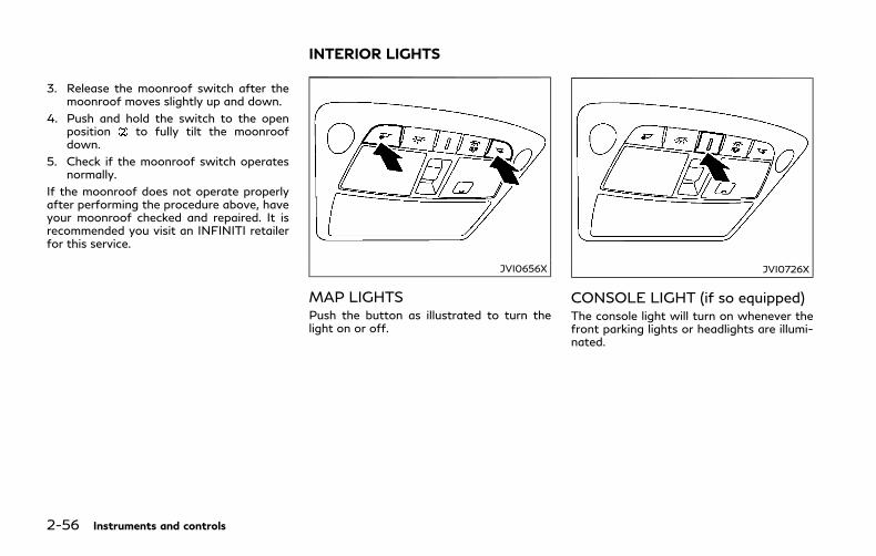
2-56 Instruments and controls
3. Release the moonroof switch after themoonroof moves slightly up and down.
4. Push and hold the switch to the openposition to fully tilt the moonroofdown.
5. Check if the moonroof switch operatesnormally.
If the moonroof does not operate properlyafter performing the procedure above, haveyour moonroof checked and repaired. It isrecommended you visit an INFINITI retailerfor this service.
JVI0656X
MAP LIGHTSPush the button as illustrated to turn thelight on or off.
JVI0726X
CONSOLE LIGHT (if so equipped)The console light will turn on whenever thefront parking lights or headlights are illumi-nated.
INTERIOR LIGHTS

SIC3250
PERSONAL LIGHTSPush the button as illustrated to turn thelight on or off.
JVI0657X
INTERIOR LIGHT CONTROLSWITCH
ON switchWhen the ON switch is pushed in, the maplights and rear personal lights will illuminate.When the switch is pushed off, the lights willnot illuminate, regardless of the condition.
DOOR OFF switchWhen the DOOR OFF switch is notpushed in, the map lights and rear personallights will illuminate under the followingconditions:
. ignition switch is switched to the OFFposition
— remain on for about 15 seconds.
. doors are unlocked by pushing the UN-LOCK button on the Intelligent Key orone touch unlock sensor with the ignitionswitch in the LOCK position
— remain on for about 15 seconds.
. any door is opened and then closed withthe ignition switch in the LOCK position
— remain on for about 15 seconds.
. any door is opened
— remain on while the door is opened.When the door is closed, the lights gooff.
When the DOOROFF switch is pushed in,the map and rear personal lights will notilluminate under the above condition. Themap and rear personal lights can be turnedon only with the ON switch .
The lights will also turn off after a period oftime when the lights remain illuminatedafter the ignition switch has been pushedto the OFF or LOCK position to prevent the12-volt battery from becoming discharged.
When [Lamp ONWhen Door Unlocks] is setto the OFF position (see the Infiniti InTouchOwner’s Manual), the lights will illuminateunder the following condition:
Instruments and controls 2-57
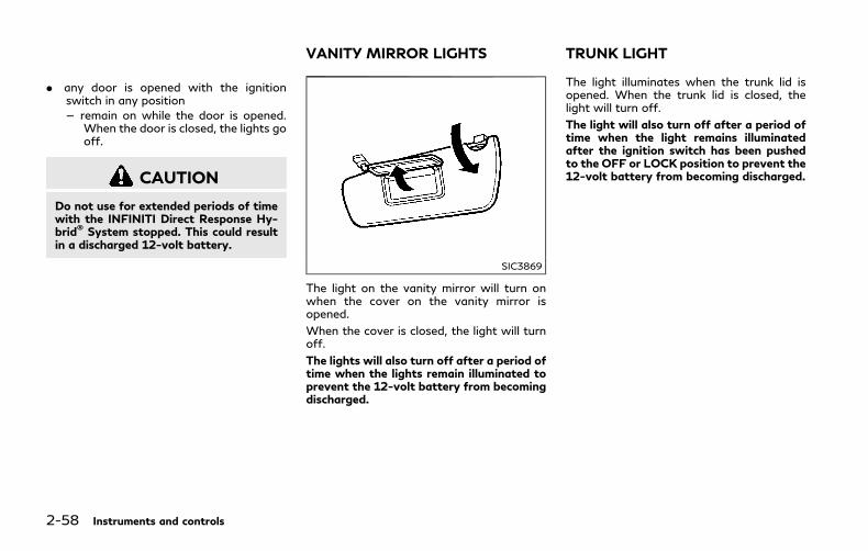
2-58 Instruments and controls
. any door is opened with the ignitionswitch in any position
— remain on while the door is opened.When the door is closed, the lights gooff.
CAUTION
Do not use for extended periods of timewith the INFINITI Direct Response Hy-brid® System stopped. This could resultin a discharged 12-volt battery.
SIC3869
The light on the vanity mirror will turn onwhen the cover on the vanity mirror isopened.
When the cover is closed, the light will turnoff.
The lights will also turn off after a period oftime when the lights remain illuminated toprevent the 12-volt battery from becomingdischarged.
The light illuminates when the trunk lid isopened. When the trunk lid is closed, thelight will turn off.
The light will also turn off after a period oftime when the light remains illuminatedafter the ignition switch has been pushedto the OFF or LOCK position to prevent the12-volt battery from becoming discharged.
VANITY MIRROR LIGHTS TRUNK LIGHT

SIC4328
When the doors are unlocked by pushing theUNLOCK button on the Intelligent Key ortouching the one touch unlock sensor withthe ignition switch in the LOCK position, thecourtesy light will illuminate.
To activate or deactivate the courtesy light,set [Lamp ONWhen Door Unlocks]. See theInfiniti InTouch Owner’s Manual.
The HomeLink® Universal Transceiver pro-vides a convenient way to consolidate thefunctions of up to three individual hand-heldtransmitters into one built-in device.
HomeLink® Universal Transceiver:
. Will operate most Radio Frequency (RF)devices such as garage doors, gates,home and office lighting, entry doorlocks and security systems.
. Is powered by your vehicle’s 12-voltbattery. No separate batteries are re-quired. If the vehicle’s 12-volt battery isd i scharged or i s d i sconnected ,HomeLink® will retain all programming.
When the HomeLink® Universal Transceiveris programmed, retain the original trans-mitter for future programming procedures(Example: new vehicle purchases). Uponsale of the vehicle, the programmedHomeLink® Universal Transceiver buttonsshould be erased for security purposes. Foradditional information, refer to “Program-ming HomeLink®” (P.2-60).
WARNING
. Do not use the HomeLink® UniversalTransceiver with any garage dooropener that lacks safety stop andreverse features as required by fed-eral safety standards. (These stan-
dards became effective for openermodels manufactured after April 1,1982). A garage door opener whichcannot detect an object in the path ofa closing garage door and then auto-matically stop and reverse, does notmeet current federal safety stan-dards. Using a garage door openerwithout these features increases therisk of serious injury or death.
. During the programming procedureyour garage door or security gate willopen and close (if the transmitter iswithin range). Make sure that peopleor objects are clear of the garagedoor, gate, etc. that you are pro-gramming.
. Your vehicle’s INFINITI Direct Re-sponse Hybrid® System should beturned off while programming theHomeLink® Universal Transceiver.Do not breathe exhaust gases; theycontain colorless and odorless carbonmonoxide. Carbon monoxide is dan-gerous. It can cause unconsciousnessor death.
Instruments and controls 2-59
COURTESY LIGHT HomeLink® UNIVERSAL TRANSCEIVER
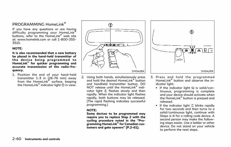
2-60 Instruments and controls
PROGRAMMING HomeLink®
If you have any questions or are havingdifficulty programming your HomeLink®
buttons, refer to the HomeLink® web siteat: www.homelink.com or call 1-800-355-3515.
NOTE:
It is also recommended that a new batterybe placed in the hand-held transmitter ofthe dev ice be ing programmed toHomeLink® for quicker programming andaccurate transmission of the radio-fre-quency.
1. Position the end of your hand-heldtransmitter 1-3 in (26-76 mm) awayfrom the HomeLink® surface, keepingthe HomeLink® indicator light in view.
JVI0428X
2. Using both hands, simultaneously pressand hold the desired HomeLink® buttonand handheld transmitter button. DONOT release until the HomeLink® indi-cator light flashes slowly and thenrapidly. When the indicator light flashesrapidly, both buttons may be released.(The rapid flashing indicates successfulprogramming.)
NOTE:Some devices to be programmed mayrequire you to replace Step 2 with thecycling procedure noted in the “Pro-gramming HomeLink® for Canadian cus-tomers and gate openers” (P.2-61).
JVI0429X
3. Press and hold the programmedHomeLink® button and observe the in-dicator light.. If the indicator light is solid/con-
tinuous, programming is completeand your device should activate whenthe HomeLink® button is pressed andreleased.
. If the indicator light blinks rapidlyfor two seconds and then turns to asolid/continuous light, continue withSteps 4-6 for a rolling code device. Asecond person may make the follow-ing steps easier. Use a ladder or otherdevice. Do not stand on your vehicleto perform the next steps.

4. At the receiver located on the garagedoor opener motor in the garage, locatethe “learn” or “smart” button (the nameand color of the button may vary bymanufacturer but it is usually locatednear where the hanging antenna wire isattached to the unit). If there is difficultylocating the button, reference the garagedoor opener’s manual.
5. Press and release the “learn” or “smart”button.
NOTE:Once the button is pressed, you haveapproximately 30 seconds to initiate thenext step.
6. Return to the vehicle and firmly pressand hold the programmed HomeLink®
button for two seconds and release.Repeat the “press/hold/release” se-quence up to 3 times to complete theprogramming process. HomeLink®
should now activate your rolling codeequipped device.
7. If you have any questions or are havingdifficulty programming your HomeLink®
buttons, refer to the HomeLink® website at: www.homelink.com or call 1-800-355-3515.
PROGRAMMING HomeLink® FORCANADIAN CUSTOMERS ANDGATE OPENERSCanadian radio-frequency laws requiretransmitter signals to “time-out” (or quit)after several seconds of transmission –which may not be long enough forHomeLink® to pick up the signal duringprogramming. Similar to this Canadian law,some U.S. gate operators are designed to“time-out” in the same manner.
If you live in Canada or you are havingdifficulties programming a gate operator orgarage door opener by using the “Program-ming HomeLink®” procedures, replace “Pro-gramming HomeLink®” Step 2 with thefollowing:
NOTE:
When programming a garage door opener,etc., unplug the device during the “cycling”process to prevent possible damage to thegarage door opener components.
Step 2: Using both hands, simultaneouslypress and hold the desired HomeLink®
button and the hand-held transmitter but-ton. During programming, your hand-heldtransmitter may automatically stop trans-mitting. Continue to press and hold thedesired HomeLink® button while you pressand re-press (“cycle”) your hand-held trans-
mitter every two seconds until the frequencysignal has been learned. The HomeLink®
indicator light will flash slowly and thenrapidly after several seconds upon success-ful programming. DO NOT release until theHomeLink® indicator light flashes slowly andthen rapidly. When the indicator light flashesrapidly, both buttons may be released. Therapid flashing indicates successful program-ming.
Proceed with “Programming HomeLink®”step 3 to complete.
Remember to plug the device back in whenprogramming is completed.
OPERATING THE HomeLink®
UNIVERSAL TRANSCEIVERThe HomeLink® Universal Transceiver, afterit is programmed, can be used to activate theprogrammed device. To operate, simplypress and release the appropriate pro-grammed HomeLink® Universal Transceiverbutton. The amber indicator light will illumi-nate while the signal is being transmitted.
For convenience, the hand-held transmitterof the device may also be used at any time.
Instruments and controls 2-61

2-62 Instruments and controls
PROGRAMMING TROUBLE-SHOOTINGIf the HomeLink® does not quickly learn thehand-held transmitter information:
. replace the hand-held transmitter bat-teries with new batteries.
. position the hand-held transmitter withits battery area facing away from theHomeLink® surface.
. press and hold both the HomeLink® andhand-held transmitter buttons withoutinterruption.
. position the hand-held transmitter 1-3 in(26-76 mm) away from the HomeLink®
surface. Hold the transmitter in thatposition for up to 15 seconds. IfHomeLink® is not programmed withinthat time, try holding the transmitter inanother position - keeping the indicatorlight in view at all times.
If you have any questions or are havingdifficulty programming your HomeLink®
buttons, refer to the HomeLink® web siteat: www.homelink.com or 1-800-355-3515.
CLEARING THE PROGRAMMEDINFORMATIONThe following procedure clears the pro-grammed information from both buttons.Individual buttons cannot be cleared. How-ever, individual buttons can be repro-grammed, see “Reprogramming a singleHomeLink® button” (P.2-62).
To clear all programming1. Press and hold the two outer HomeLink®
buttons until the indicator light begins toflash in approximately 10 seconds. Donot hold for longer than 20 seconds.
2. Release both buttons.
HomeLink® is now in the programmingmodeand can be programmed at any time begin-ning with “Programming HomeLink®” - Step1.
REPROGRAMMING A SINGLEHomeLink® BUTTONTo reprogram aHomeLink® Universal Trans-ceiver button, complete the following.
1. Press and hold the desired HomeLink®
button. Do not release the button.
2. The indicator light will begin to flashafter 20 seconds. Without releasing theHomeLink® button, proceed with “Pro-gramming HomeLink®” - Step 1.
For questions or comments, contactHomeLink® at: www.homelink.com or 1-800-355-3515.
The HomeLink® Universal Transceiver but-ton has now been reprogrammed. The newdevice can be activated by pushing theHomeLink® button that was just pro-grammed. This procedure will not affectany other programmed HomeLink® buttons.
IF YOUR VEHICLE IS STOLENIf your vehicle is stolen, you should changethe codes of any non-rolling code device thathas been programmed into HomeLink®.Consult the Owner’s Manual of each deviceor call the manufacturer or retailer of thosedevices for additional information.
When your vehicle is recovered, you willneed to reprogram the HomeLink® Univer-sal Transceiver with your new transmitterinformation.
FCC Notice:
For USA:
This device complies with Part 15 of theFCC Rules. Operation is subject to thefollowing two conditions: (1) This devicemay not cause harmful interference, and (2)this device must accept any interferencereceived, including interference that maycause undesired operation.

NOTE:
Changes or modifications not expresslyapproved by the party responsible forcompliance could void the user’s authorityto operate the equipment.
For Canada:
This device complies with Industry Canadalicence-exempt RSS standard(s). Operationis subject to the following two conditions:(1) this device may not cause interference,and (2) this device must accept any inter-ference, including interference that maycause undesired operation of the device.
Instruments and controls 2-63

2-64 Instruments and controls
MEMO

3 Pre-driving checks and adjustments
Keys ....................................................................................... 3-2
Intelligent Key ............................................................... 3-2
Valet hand-off .............................................................. 3-3
Doors .................................................................................... 3-4
Locking with mechanical key.................................... 3-4
Opening and closing windows withmechanical key.............................................................. 3-4
Locking with inside lock knob .................................. 3-5
Locking with power door lock switch.................... 3-5
Automatic door locks.................................................. 3-5
Child safety rear door lock........................................ 3-6
Intelligent Key system ...................................................... 3-6
Intelligent Key operating range ............................... 3-8
Door locks/unlocks precaution ............................... 3-9
Intelligent Key operation ........................................... 3-9
Battery saver system ................................................ 3-13
Warning signals .......................................................... 3-13
Troubleshooting guide.............................................. 3-14
Log-in function ........................................................... 3-15
Remote keyless entry system ...................................... 3-15
How to use remote keyless entry system........... 3-16
Remote engine start ....................................................... 3-19
Remote engine start operating range.................. 3-19
Remote starting the engine .................................... 3-19
Extending engine run time ................................... 3-20
Canceling a remote start ...................................... 3-20
Conditions the remote start will not work ...... 3-20
Hood................................................................................... 3-21
Trunk lid............................................................................. 3-22
Trunk lid release switch ......................................... 3-22
Trunk open request switch ................................... 3-22
TRUNK button.......................................................... 3-23
Trunk release power cancel switch .................... 3-23
Interior trunk lid release ......................................... 3-24
Fuel-filler door................................................................. 3-24
Opening the fuel-filler door .................................. 3-24
Fuel-filler cap ............................................................ 3-25
Tilt/telescopic steering ................................................. 3-27
Electric operation..................................................... 3-27
Sun visors .......................................................................... 3-27
Mirrors ............................................................................... 3-28
Inside mirror .............................................................. 3-28
Outside mirrors......................................................... 3-29
Vanity mirror ............................................................ 3-30
Automatic drive positioner ......................................... 3-30
Entry/exit function................................................. 3-30
Memory storage....................................................... 3-31
System operation..................................................... 3-32
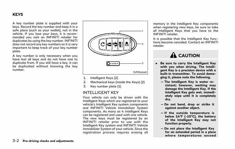
3-2 Pre-driving checks and adjustments
A key number plate is supplied with yourkeys. Record the key number and keep it in asafe place (such as your wallet), not in thevehicle. If you lose your keys, it is recom-mended you visit an INFINITI retailer forduplicates by using the key number. INFINITIdoes not record any key numbers so it is veryimportant to keep track of your key numberplate.
A key number is only necessary when youhave lost all keys and do not have one toduplicate from. If you still have a key, it canbe duplicated without knowing the keynumber.
JVP0414X
1. Intelligent Keys (2)
2. Mechanical keys (inside the Keys) (2)
3. Key number plate (1)
INTELLIGENT KEYYour vehicle can only be driven with theIntelligent Keys which are registered to yourvehicle’s Intelligent Key system componentsand INFINITI Vehicle Immobilizer Systemcomponents. As many as 4 Intelligent Keyscan be registered and used with one vehicle.The new keys must be registered by anINFINITI retailer prior to use with theIntelligent Key system and INFINITI VehicleImmobilizer System of your vehicle. Since theregistration process requires erasing all
memory in the Intelligent Key componentswhen registering new keys, be sure to takeall Intelligent Keys that you have to theINFINITI retailer.
It is possible that the Intelligent Key func-tions become canceled. Contact an INFINITIretailer.
CAUTION
. Be sure to carry the Intelligent Keywith you when driving. The Intelli-gent Key is a precision device with abuilt-in transmitter. To avoid dama-ging it, please note the following.
— The Intelligent Key is water re-sistant; however, wetting maydamage the Intelligent Key. If theIntelligent Key gets wet, immedi-ately wipe until it is completelydry.
— Do not bend, drop or strike itagainst another object.
— If the outside temperature isbelow 14°F (−10°C), the batteryof the Intelligent Key may notfunction properly.
— Do not place the Intelligent Keyfor an extended period in a placewhere temperatures exceed
KEYS
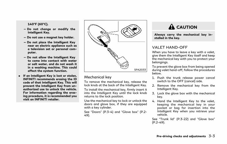
140°F (60°C).
— Do not change or modify theIntelligent Key.
— Do not use a magnet key holder.
— Do not place the Intelligent Keynear an electric appliance such asa television set or personal com-puter.
— Do not allow the Intelligent Keyto come into contact with wateror salt water, and do not wash itin a washing machine. This couldaffect the system function.
. If an Intelligent Key is lost or stolen,INFINITI recommends erasing the IDcode of that Intelligent Key. This willprevent the Intelligent Key from un-authorized use to unlock the vehicle.For information regarding the eras-ing procedure, it is recommended youvisit an INFINITI retailer.
SPA2033
Mechanical keyTo remove the mechanical key, release thelock knob at the back of the Intelligent Key.
To install the mechanical key, firmly insert itinto the Intelligent Key until the lock knobreturns to the lock position.
Use the mechanical key to lock or unlock thedoors and glove box, if they are equippedwith a key cylinder.
See “Doors” (P.3-4) and “Glove box” (P.2-49).
CAUTION
Always carry the mechanical key in-stalled in the key.
VALET HAND-OFFWhen you have to leave a key with a valet,give them the Intelligent Key itself and keepthe mechanical key with you to protect yourbelongings.
To prevent the glove box from being openedduring valet hand-off, follow the proceduresbelow.
1. Push the trunk release power cancelswitch to the OFF (cancel) side.
2. Remove the mechanical key from theIntelligent Key.
3. Lock the glove box with the mechanicalkey.
4. Hand the Intelligent Key to the valet,keeping the mechanical key in yourpocket or bag for insertion into theIntelligent Key when you retrieve yourvehicle.
See “Trunk lid” (P.3-22) and “Glove box”(P.2-49).
Pre-driving checks and adjustments 3-3

3-4 Pre-driving checks and adjustments
WARNING
. Always have the doors locked whiledriving. Along with the use of seatbelts, this provides greater safety inthe event of an accident by helping toprevent persons from being thrownfrom the vehicle. This also helps keepchildren and others from unintention-ally opening the doors, and will helpkeep out intruders.
. Before opening any door, always lookfor and avoid oncoming traffic.
. To help avoid risk of injury or deaththrough unintended operation of thevehicle and or its systems, includingentrapment in windows or inadver-tent door lock activation, do notleave children, people who requirethe assistance of others or petsunattended in your vehicle. Addition-ally, the temperature inside a closedvehicle on a warm day can quicklybecome high enough to cause a sig-nificant risk of injury or death topeople and pets.
JVP0231X
LOCKING WITH MECHANICALKEYThe power door lock system allows you tolock or unlock all doors and trunk lidsimultaneously using the mechanical key.
. Turning the driver’s door key cylinder tothe front of the vehicle will lock alldoors and trunk lid.
. Turning the driver’s door key cylinderonce to the rear of the vehicle willunlock the driver’s door. After returningthe key to the neutral position , turningit to the rear again within 60 secondswillunlock all doors.
. You can switch the lock system to themode that allows you to open all thedoors and trunk lid when the key isturned once. (See the Infiniti InTouchOwner’s Manual for details.)
OPENING AND CLOSING WIN-DOWS WITH MECHANICAL KEYThe driver’s door key operation also allowsyou to open and close the window that isequipped with the automatic open/closefunction. (See “Power windows” (P.2-52).)
To open the window, turn the driver’s doorkey cylinder to the rear of the vehicle forlonger than 1 second. The door is unlockedand the window keeps opening while turningthe key.
This function can also be performed bypushing and holding the UNLOCK buttonon the Intelligent Key. (See “Remote keylessentry system” (P.3-15).)
To close the window, turn the driver’s doorkey cylinder to the front of the vehicle forlonger than 1 second. The door is locked andthe window keeps closing while turning thekey.
DOORS

SPA2726
LOCKING WITH INSIDE LOCKKNOBTo lock the door individually, move the insidelock knob to the lock position then closethe door.
To unlock, move the inside lock knob to theunlock position .
When locking the door without an Intelli-gent Key, be sure not to leave the IntelligentKey inside the vehicle.
JVP0319X
LOCKING WITH POWER DOORLOCK SWITCHOperating the power door lock switch willlock or unlock all the doors and trunk lid. Theswitches are located on the driver’s andfront passenger’s door armrests.
To lock the doors and trunk lid, push thepower door lock switch to the lock positionwith the driver’s or front passenger’s door
open, then close the door.
When locking the door this way, be certainnot to leave the Intelligent Key inside thevehicle.
To unlock the doors, trunk lid and fuel-fillerdoor, push the power door lock switch to the
unlock position .
Lockout protectionWhen the power door lock switch is movedto the lock position and any door open, alldoors will lock and unlock automatically.With the Intelligent Key left in the vehicleand any door open, all doors will unlockautomatically and a chime will sound afterthe door is closed.
These functions help to prevent the Intelli-gent Key from being accidentally lockedinside the vehicle.
AUTOMATIC DOOR LOCKS. All doors and trunk lid lock automatically
when the vehicle speed reaches 15 MPH(24 km/h).
. All doors and trunk lid unlock automati-cally when the ignition switch is placed inthe OFF position or when the shift leveris moved to the P (Park) position, ifselected.
The automatic unlock function can bedeactivated or activated. To deactivate oractivate the automatic door unlock system,perform the following procedure:
1. Close all doors.
2. Place the ignition switch in the ONposition.
Pre-driving checks and adjustments 3-5

3-6 Pre-driving checks and adjustments
3. Within 20 seconds of performing Step 2,push and hold the power door lockswitch to the position (UNLOCK)for more than 5 seconds.
4. When activated, the hazard indicator willflash twice. When deactivated, the ha-zard indicator will flash once.
5. The ignition switch must be placed in theOFF and ON position again betweeneach setting change.
When the automatic door unlock system isdeactivated, the doors do not unlock whenthe ignition switch is placed in the OFFposition. To unlock the door manually, usethe inside lock knob or the power door lockswitch (driver’s or front passenger’s side).
The automatic door unlock function can bechanged on the lower display. (See theInfiniti InTouch Owner’s Manual.)
SPA2536
CHILD SAFETY REAR DOORLOCKThe child safety rear door lock helps preventdoors from being opened accidentally, espe-cially when small children are in the vehicle.
When the levers are in the lock position ,the rear doors can be opened only from theoutside.
To disengage, move the levers to the unlockposition .
WARNING
. Radio waves could adversely affectelectric medical equipment. Thosewho use a pacemaker should contactthe electric medical equipment man-ufacturer for the possible influencesbefore use.
. The Intelligent Key transmits radiowaves when the buttons are pushed.The FAA advises that the radiowaves may affect aircraft navigationand communication systems. Do notoperate the Intelligent Key while onan airplane. Make sure the buttonsare not operated unintentionallywhen the unit is stored during aflight.
The Intelligent Key system can operate allthe doors and the trunk lid using the remotecontroller function, using one touch unlockfunction or pushing the request switch onthe vehicle without taking the key out from apocket or purse. The operating environmentand/or conditions may affect the IntelligentKey system operation.
Be sure to read the following before usingthe Intelligent Key system.
INTELLIGENT KEY SYSTEM
CAUTION
. Be sure to carry the Intelligent Keywith you when operating the vehicle.
. Never leave the Intelligent Key in thevehicle when you leave the vehicle.
The Intelligent Key is always communicatingwith the vehicle as it receives radio waves.The Intelligent Key system transmits weakradio waves. Environmental conditions mayinterfere with the operation of the IntelligentKey system under the following operatingconditions.
. When operating near a location wherestrong radio waves are transmitted, suchas a TV tower, power station and broad-casting station.
. When in possession of wireless equip-ment, such as a cellular telephone,transceiver, and CB radio.
. When the Intelligent Key is in contactwith or covered by metallic materials.
. When any type of radio wave remotecontrol is used nearby.
. When the Intelligent Key is placed nearan electric appliance such as a personalcomputer.
. When the vehicle is parked near a parkingmeter.
In such cases, correct the operating condi-tions before using the Intelligent Key func-tion or use the mechanical key.
Although the life of the battery variesdepending on the operating conditions, thebattery’s life is approximately 2 years. If thebattery is discharged, replace it with a newone.
When the Intelligent Key battery is almostdischarged, see “Intelligent Key battery dis-charge” (P.5-13) to start the hybrid system.
Since the Intelligent Key is continuouslyreceiving radio waves, if the key is left nearequipment which transmits strong radiowaves, such as signals from a TV andpersonal computer, the battery life maybecome shorter.
For information regarding replacement of abattery, see “Intelligent Key battery replace-ment” (P.8-21).
As many as 4 Intelligent Keys can beregistered and used with one vehicle. Forinformation about the purchase and use ofadditional Intelligent Keys, contact anINFINITI retailer.
CAUTION
. Do not allow the Intelligent Key,which contains electrical compo-nents, to come into contact withwater or salt water. This could affectthe system function.
. Do not drop the Intelligent Key.
. Do not strike the Intelligent Keysharply against another object.
. Do not change or modify the Intelli-gent Key.
. Wetting may damage the IntelligentKey. If the Intelligent Key gets wet,immediately wipe until it is comple-tely dry.
. Do not place the Intelligent Key foran extended period in an area wheretemperatures exceed 140°F (60°C).
. If the outside temperature is below14°F (−10°C), the battery of theIntelligent Key may not functionproperly.
. Do not attach the Intelligent Keywith a key holder that contains amagnet.
. Do not place the Intelligent Key nearequipment that produces a magneticfield, such as a TV, audio equipment
Pre-driving checks and adjustments 3-7
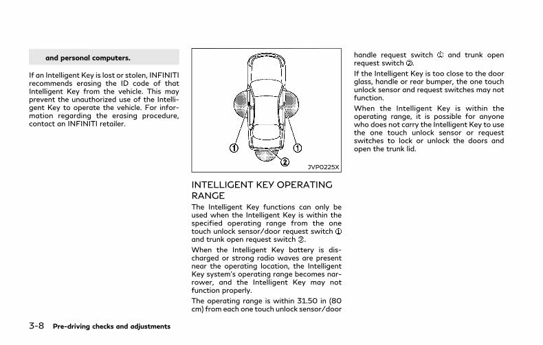
3-8 Pre-driving checks and adjustments
and personal computers.
If an Intelligent Key is lost or stolen, INFINITIrecommends erasing the ID code of thatIntelligent Key from the vehicle. This mayprevent the unauthorized use of the Intelli-gent Key to operate the vehicle. For infor-mation regarding the erasing procedure,contact an INFINITI retailer.
JVP0225X
INTELLIGENT KEY OPERATINGRANGEThe Intelligent Key functions can only beused when the Intelligent Key is within thespecified operating range from the onetouch unlock sensor/door request switchand trunk open request switch .
When the Intelligent Key battery is dis-charged or strong radio waves are presentnear the operating location, the IntelligentKey system’s operating range becomes nar-rower, and the Intelligent Key may notfunction properly.
The operating range is within 31.50 in (80cm) from each one touch unlock sensor/door
handle request switch and trunk openrequest switch .
If the Intelligent Key is too close to the doorglass, handle or rear bumper, the one touchunlock sensor and request switches may notfunction.
When the Intelligent Key is within theoperating range, it is possible for anyonewho does not carry the Intelligent Key to usethe one touch unlock sensor or requestswitches to lock or unlock the doors andopen the trunk lid.

SPA2407
DOOR LOCKS/UNLOCKS PRE-CAUTION. Do not push the door handle request
switch with the Intelligent Key held inyour hand as illustrated. The close dis-tance to the door handle will cause theIntelligent Key system to have difficultyrecognizing that the Intelligent Key isoutside the vehicle.
. Within 2 seconds after the door arelocked using the door handle requestswitch, make sure that the doors havebeen securely locked by operating thedoor handles. If you keep holding thedoor handle for more than 2 secondsafter locking the doors using the door
handle request switch, the door will beunlocked.
. To prevent the Intelligent Key from beingleft inside the vehicle or the trunk, makesure you carry the key with you and thenlock the doors or the trunk.
. The Intelligent Key system (opening/closing doors with the door handlerequest switch or one touch unlocksensor) can be set to remain inactive.(See the Infiniti InTouch Owner’s Man-ual.)
. The door cannot be unlocked using onetouch unlock operation after locking thedoor within 2 seconds. To unlock thedoor, release the door handle once andhold it again.
. If a large amount of water runs down onthe door handle (for example, whenwashing the vehicle or in a heavy rain),the door may unlock if the Intelligent Keyis within the range of operation. Toprevent the door from being unlocked,the Intelligent Key should be away fromthe vehicle more than 7 ft (2 m).
. Do not hold and pull the door handlequickly. The door will be unlocked but willnot open. Release the door handle onceand pull it again to open the door.
. If you pull the door handle with yourgloved hand, the one touch unlockoperation may not function.
JVP0418X
INTELLIGENT KEY OPERATIONYou can lock or unlock the doors withouttaking the key out from your pocket or bag.
Pre-driving checks and adjustments 3-9

3-10 Pre-driving checks and adjustments
JVP0233X
When you carry the Intelligent Key with you,you can lock all doors by pushing the doorhandle request switch (driver’s or frontpassenger’s) within the range of operation.
JVP0350X
You can also unlock the corresponding doorby touching the one touch unlock sensor(driver’s or front passenger’s) within therange of operation, and can unlock the otherdoors using the door handle request switch.
When you lock or unlock the doors or thetrunk lid, the hazard indicator will flash andthe horn (or the outside chime) will sound asa confirmation. For details, see “Settinghazard indicator and horn mode” (P.3-17).
CAUTION
. After locking the doors using therequest switch, make sure that thedoors have been securely locked byoperating the door handles. (Performthis confirmation within 2 secondsafter the doors are locked.)
. When locking the doors using therequest switch, make sure to have theIntelligent Key in your possessionbefore operating the request switchto prevent the Intelligent Key frombeing left in the vehicle.
. The request switch and one touchunlock sensor are operational onlywhen the Intelligent Key has beendetected by the Intelligent Key sys-tem.
Welcome light and farewell lightfunctionWhen you lock or unlock the doors and fuel-filler door, front and rear side marker lights,parking lights, tail lights and the license platelight will illuminate for a period of time. Thewelcome light and farewell light function canbe disabled. For information about disablingthe welcome light and farewell light func-
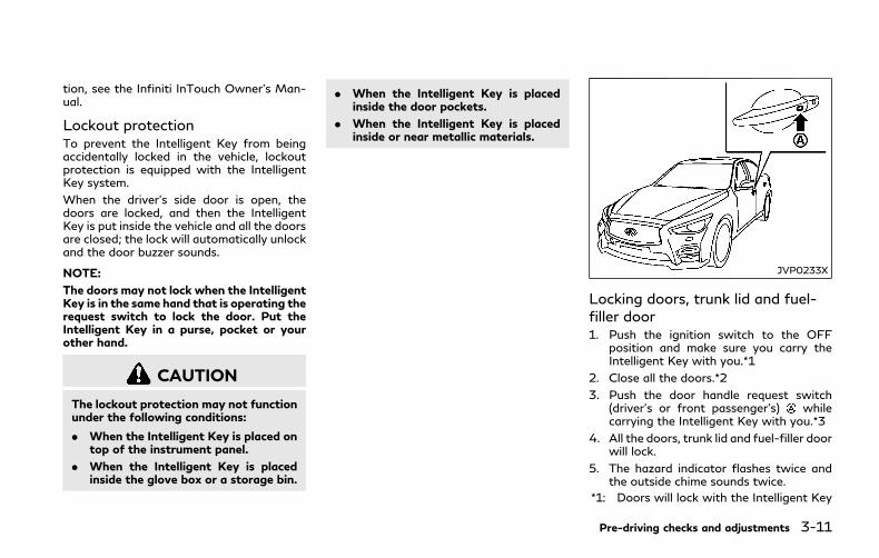
tion, see the Infiniti InTouch Owner’s Man-ual.
Lockout protectionTo prevent the Intelligent Key from beingaccidentally locked in the vehicle, lockoutprotection is equipped with the IntelligentKey system.
When the driver’s side door is open, thedoors are locked, and then the IntelligentKey is put inside the vehicle and all the doorsare closed; the lock will automatically unlockand the door buzzer sounds.
NOTE:
The doors may not lock when the IntelligentKey is in the same hand that is operating therequest switch to lock the door. Put theIntelligent Key in a purse, pocket or yourother hand.
CAUTION
The lockout protection may not functionunder the following conditions:
. When the Intelligent Key is placed ontop of the instrument panel.
. When the Intelligent Key is placedinside the glove box or a storage bin.
. When the Intelligent Key is placedinside the door pockets.
. When the Intelligent Key is placedinside or near metallic materials.
JVP0233X
Locking doors, trunk lid and fuel-filler door1. Push the ignition switch to the OFF
position and make sure you carry theIntelligent Key with you.*1
2. Close all the doors.*2
3. Push the door handle request switch(driver’s or front passenger’s) whilecarrying the Intelligent Key with you.*3
4. All the doors, trunk lid and fuel-filler doorwill lock.
5. The hazard indicator flashes twice andthe outside chime sounds twice.
*1: Doors will lock with the Intelligent Key
Pre-driving checks and adjustments 3-11
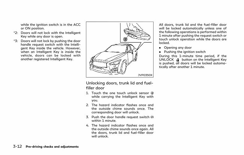
3-12 Pre-driving checks and adjustments
while the ignition switch is in the ACCor ON position.
*2: Doors will not lock with the IntelligentKey while any door is open.
*3: Doors will not lock by pushing the doorhandle request switch with the Intelli-gent Key inside the vehicle. However,when an Intelligent Key is inside thevehicle, doors can be locked withanother registered Intelligent Key.
JVP0350X
Unlocking doors, trunk lid and fuel-filler door1. Touch the one touch unlock sensor
while carrying the Intelligent Key withyou.
2. The hazard indicator flashes once andthe outside chime sounds once. Thecorresponding door will unlock.
3. Push the door handle request switchwithin 1 minute.
4. The hazard indicator flashes once andthe outside chime sounds once again. Allthe doors, trunk lid and fuel-filler doorwill unlock.
All doors, trunk lid and the fuel-filler doorwill be locked automatically unless one ofthe following operations is performed within1 minute after pushing the request switch ortouch unlock operation while the doors arelocked.
. Opening any door
. Pushing the ignition switch
During this 1-minute time period, if theUNLOCK button on the Intelligent Keyis pushed, all doors will be locked automa-tically after another 1 minute.
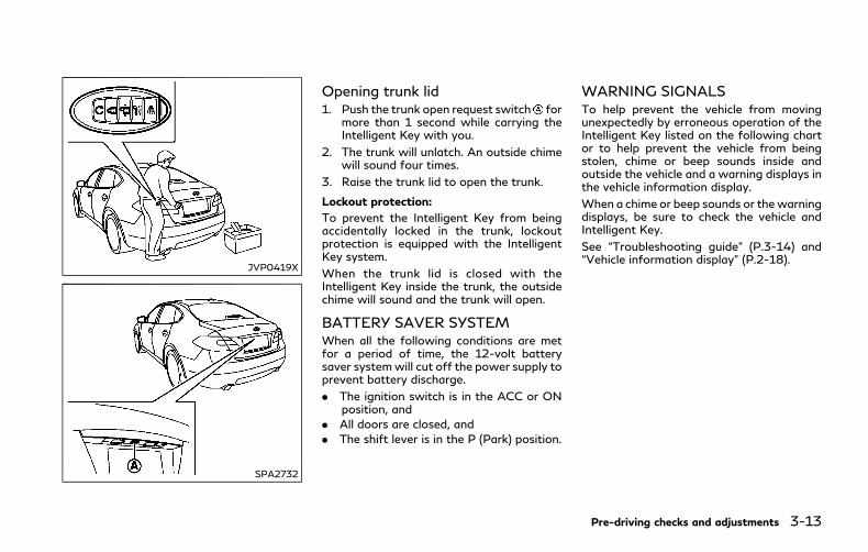
JVP0419X
SPA2732
Opening trunk lid1. Push the trunk open request switch for
more than 1 second while carrying theIntelligent Key with you.
2. The trunk will unlatch. An outside chimewill sound four times.
3. Raise the trunk lid to open the trunk.
Lockout protection:
To prevent the Intelligent Key from beingaccidentally locked in the trunk, lockoutprotection is equipped with the IntelligentKey system.
When the trunk lid is closed with theIntelligent Key inside the trunk, the outsidechime will sound and the trunk will open.
BATTERY SAVER SYSTEMWhen all the following conditions are metfor a period of time, the 12-volt batterysaver systemwill cut off the power supply toprevent battery discharge.
. The ignition switch is in the ACC or ONposition, and
. All doors are closed, and
. The shift lever is in the P (Park) position.
WARNING SIGNALSTo help prevent the vehicle from movingunexpectedly by erroneous operation of theIntelligent Key listed on the following chartor to help prevent the vehicle from beingstolen, chime or beep sounds inside andoutside the vehicle and a warning displays inthe vehicle information display.
When a chime or beep sounds or thewarningdisplays, be sure to check the vehicle andIntelligent Key.
See “Troubleshooting guide” (P.3-14) and“Vehicle information display” (P.2-18).
Pre-driving checks and adjustments 3-13

3-14 Pre-driving checks and adjustments
TROUBLESHOOTING GUIDE
Symptom Possible cause Action to take
When pushing the ignitionswitch to stop the INFINITIDirect Response Hybrid® Sys-tem
The SHIFT P warning appears on thedisplay and the inside warning chimesounds continuously.
The shift lever is not in the P (Park)position.
Shift the shift lever to the P (Park)position.
When shifting the shift lever tothe P (Park) position.
The inside warning chime sounds continu-ously.
The ignition switch is in the ACC orON position.
Push the ignition switch to the OFFposition.
When opening the driver’s doorto get out of the vehicle
The inside warning chime sounds continu-ously.
The ignition switch is in the ACCposition.
Push the ignition switch to the OFFposition.
When closing the door aftergetting out of the vehicle
The NO KEY warning appears on thedisplay, the outside chime sounds 3 timesand the inside warning chime sounds for afew seconds.
The ignition switch is in the ACC orON position.
Push the ignition switch to the OFFposition.
The SHIFT P warning appears on thedisplay and the outside chime soundscontinuously.
The ignition switch is in the ACC orOFF position and the shift lever is notin the P (Park) position.
Move the shift lever to the P (Park)position and push the ignition switch tothe OFF position.
When closing the door with theinside lock knob turned toLOCK
The outside chime sounds for a fewseconds and all the doors unlock.
The Intelligent Key is inside thevehicle or trunk.
Carry the Intelligent Key with you.
When pushing the requestswitch or LOCK button on theIntelligent Key to lock the door
The outside chime sounds for a fewseconds.
The Intelligent Key is inside thevehicle or trunk.
Carry the Intelligent Key with you.
A door is not closed securely. Close the door securely.
When closing the trunk lidThe outside chime sounds for approxi-mately 10 seconds and the trunk lid opens.
The Intelligent Key is inside the trunk. Carry the Intelligent Key with you.

LOG-IN FUNCTIONAfter setting up the user information, thesystem will automatically recognize the userupon turning on the vehicle.
There will be a personalized welcome greet-ing and screen prompt to log-in.
This feature allows 4 drivers to use theirown registration, drive mode, driving posi-tion, air conditioner, and auto settings andmemorizes these custom settings.
The log-in user can be changed on thewelcome greeting screen or the User Listscreen. For more details, see the InfinitiInTouch Owner’s Manual.
The log-in function is linked to the followingitems:
. Meter
. Audio
. Navigation system display
. Navigation settings
. Air conditioner
. Automatic drive positioner
. Engine/Transmission
. Steering
. Active trace control
. Driver assistance*
. Body Control Module (BCM)
*: except for the Forward Emergency Brak-ing (FEB) system
WARNING
The Intelligent Key transmits radiowaves when the buttons are pushed.The FAA advises that the radio wavesmay affect aircraft navigation and com-munication systems. Do not operate theIntelligent Key while on an airplane.Make sure the buttons are not operatedunintentionally when the unit is storedduring a flight.
It is possible to lock/unlock all doors andfuel-filler door, open the trunk lid, activatethe panic alarm and open the windows bypushing the buttons on the Intelligent Keyfrom outside the vehicle.
Before locking the doors, make sure theIntelligent Key is not left in the vehicle.
The remote keyless entry function canoperate at a distance of approximately 33ft (10 m) from the vehicle. (The effectivedistance depends upon the conditionsaround the vehicle.)
As many as 4 Intelligent Keys can be usedwith one vehicle. For information concerningthe purchase and use of additional Intelli-gent Keys, contact an INFINITI retailer.
The buttons on the Intelligent Key will not
operate when:
. the distance between the Intelligent Keyand the vehicle is over 33 ft (10 m).
. the Intelligent Key battery is discharged.
After locking with the remote keyless entryfunction, pull the door handle to make surethe doors are securely locked. (Perform thisconfirmation within 2 seconds after thedoors are locked.)
The LOCK/UNLOCK operating range variesdepending on the environment. To securelyoperate the lock and unlock buttons, ap-proach the vehicle to about 3 ft (1 m) fromthe door.
Pre-driving checks and adjustments 3-15
REMOTE KEYLESS ENTRY SYSTEM

3-16 Pre-driving checks and adjustments
JVP0409X
1. LOCK button
2. UNLOCK button
3. TRUNK button
4. PANIC button
5. Remote engine start button
HOW TO USE REMOTE KEYLESSENTRY SYSTEMWhen you lock or unlock the doors or thetrunk lid, the hazard indicator will flash andthe horn (or the outside chime) will sound asa confirmation. For details, see “Settinghazard indicator and horn mode” (P.3-17).
Locking doors, trunk lid and fuel-filler door1. Push the ignition switch to the OFF
position and make sure you carry theIntelligent Key with you.*1
2. Close all the doors.
3. Push the LOCK button on theIntelligent Key.
4. All the doors, trunk lid and fuel-filler doorwill lock.
5. The hazard indicator flashes twice andthe horn chirps once.
*1: Doors will lock with the Intelligent Keywhile the ignition switch is in the ACCor ON position.
Unlocking doors, trunk lid and fuel-filler door1. Push the UNLOCK button on the
Intelligent Key once.
2. The hazard indicator flashes once. Thedriver’s door will unlock.
3. Push the UNLOCK button on theIntelligent Key again within 1 minute.
4. The hazard indicator flashes once again.All the doors, trunk lid and fuel-filler doorwill unlock.
All doors, trunk lid and fuel-filler door will be
locked automatically unless one of thefollowing operations is performed within 1minute after pushing the UNLOCK
button on the Intelligent Key whilethe doors are locked. If during this 1-minutetime period, the UNLOCK button onthe Intelligent Key is pushed, all doors will belocked automatically after another 1 minute.
. Opening any door
. Pushing the ignition switch
Opening windowsThe UNLOCK button operation alsoallows you to open the window that isequipped with the automatic open/closefunction. (See “Power windows” (P.2-52).)
To open the window, push the door UN-LOCK button on the Intelligent Keyfor about 3 seconds after the door isunlocked.
To stop opening, release the UNLOCKbutton .
If the window open operation is stopped inmid-operation while pushing the UNLOCK
button , release and push the UN-LOCK button again until the windowopens completely.
Window cannot be closed using the Intelli-gent Key.
The door window can also be operated by

turning the mechanical key in a door lock.(See “Doors” (P.3-4).)
Opening moonroofThe moonroof can be opened by pushing theUNLOCK button on the IntelligentKey. This function will not operate while themoonroof timer is activated or when thewindows need to be initialized.
To open the moonroof, push the UNLOCKbutton on the Intelligent Key for
about 3 seconds after the door is unlocked.
To stop opening, release the UNLOCKbutton .
Opening trunk lid1. Push the TRUNK button on the
Intelligent Key for more than 1 second.
2. The trunk will unlatch.
3. Raise the trunk lid to open the trunk.
Using panic alarmIf you are near your vehicle and feelthreatened, you may activate the alarm tocall attention as follows:
1. Push the PANIC button on the keyfor more than 1 second.
2. The theft warning alarm and headlightswill stay on for 25 seconds.
3. The panic alarm stops when:. It has run for 25 seconds, or. Any of the buttons on the Intelligent
Key are pushed. (Note: PANICbutton or TRUNK buttonshould be pushed for more than 1second.)
Remote engine startThe remote engine start button is onthe Intelligent Key if the vehicle has remoteengine start function. This function allowsthe engine to start from outside the vehicle.See “Remote engine start” (P.3-19) for moredetails.
Setting hazard indicator and hornmodeThis vehicle is set in hazard indicator andhornmodewhen you first receive the vehicle.
In hazard indicator and horn mode, when theLOCK button is pushed, the hazardindicator flashes twice and the horn chirpsonce. When the UNLOCK button ispushed, the hazard indicator flashes once.
If horns are not necessary, the system can beswitched to the hazard indicator mode.
In hazard indicator mode, when the LOCKbutton is pushed, the hazard indicator
flashes twice. When the UNLOCKbutton is pushed, neither the hazard
indicator nor the horn operates.
Pre-driving checks and adjustments 3-17
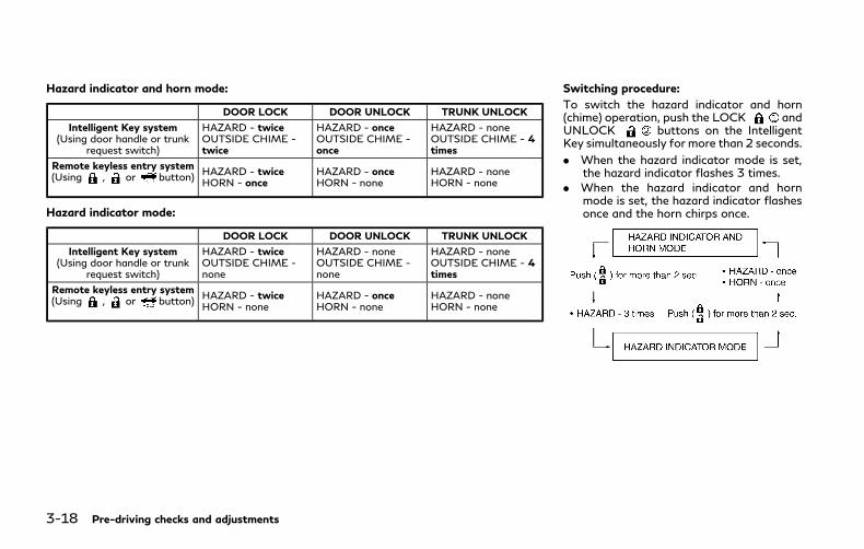
3-18 Pre-driving checks and adjustments
Hazard indicator and horn mode:
DOOR LOCK DOOR UNLOCK TRUNK UNLOCK
Intelligent Key system(Using door handle or trunk
request switch)
HAZARD - twiceOUTSIDE CHIME -twice
HAZARD - onceOUTSIDE CHIME -once
HAZARD - noneOUTSIDE CHIME - 4times
Remote keyless entry system(Using , or button)
HAZARD - twiceHORN - once
HAZARD - onceHORN - none
HAZARD - noneHORN - none
Hazard indicator mode:
DOOR LOCK DOOR UNLOCK TRUNK UNLOCK
Intelligent Key system(Using door handle or trunk
request switch)
HAZARD - twiceOUTSIDE CHIME -none
HAZARD - noneOUTSIDE CHIME -none
HAZARD - noneOUTSIDE CHIME - 4times
Remote keyless entry system(Using , or button)
HAZARD - twiceHORN - none
HAZARD - onceHORN - none
HAZARD - noneHORN - none
Switching procedure:
To switch the hazard indicator and horn(chime) operation, push the LOCK andUNLOCK buttons on the IntelligentKey simultaneously for more than 2 seconds.
. When the hazard indicator mode is set,the hazard indicator flashes 3 times.
. When the hazard indicator and hornmode is set, the hazard indicator flashesonce and the horn chirps once.

WARNING
To avoid risk of injury or death, do notuse the remote engine start functionwhen the vehicle is in an enclosed areasuch as a garage.
JVP0437X
The remote engine start button is on theIntelligent Key if the vehicle has remoteengine start function. This function allowsthe engine to start from outside the vehicle.
Automatic climate control system will auto-matically adjust the passenger compartmentto be the set appropriate temperature whenthe remote engine start function is used.
Laws in some local communities may restrictthe use of remote starters. For example,some laws require a person using remotestart to have the vehicle in view. Check localregulations for any requirements.
Other conditions may affect the remoteengine start function. See “Conditions theremote start will not work” (P.3-20).
Other conditions can affect the performanceof the Intelligent Key transmitter. See “In-telligent Key system” (P.3-6).
REMOTE ENGINE START OPER-ATING RANGEThe remote engine start function can only beused when the Intelligent Key is within thespecified operating range from the vehicle.
When the Intelligent Key battery is dis-charged or strong radio waves are presentnear the operating location, the IntelligentKey operating range becomes narrower, andthe Intelligent Key may not function prop-erly.
The remote engine start operating range isapproximately 197 ft (60 m) from thevehicle.
REMOTE STARTING THE ENGINETo use the remote start function to start theengine, perform the following:
1. Aim the Intelligent Key at the vehicle.
2. Push the LOCK button to lock alldoors.
3. Within 5 seconds push and hold theremote engine start button untilthe turn signal lights illuminate. If thevehicle is not within view, push and holdthe remote engine start button for
Pre-driving checks and adjustments 3-19
REMOTE ENGINE START
3-20 Pre-driving checks and adjustments
about 2 seconds.
The following events will occur when theengine starts:
. The front parking lights will turn on andremain on as long as the engine isrunning.
. The doors will be locked and the airconditioner system may turn on.
. The engine will continue to run for about10 minutes. Repeat the steps to extendthe time for an additional 10 minutes.See “Extending engine run time” (P.3-20).
Depress the brake pedal and place theignition switch in the ON position beforedriving. For further instructions, see “Drivingthe vehicle” (P.5-15).
EXTENDING ENGINE RUN TIMEThe remote engine start function can beextended one time by performing the stepslisted in “Remote starting the engine” (P.3-19). Run time will be calculated as follows:
. The first 10 minute run time will startwhen the remote engine start function isperformed.
. The second 10 minutes will start imme-diately when the remote engine startfunction is performed. For example, ifthe engine has been running for 5minutes, and 10 minutes are added, the
engine will run for a total of 15 minutes.
. Extending engine run time will counttowards the two remote start limit.
A maximum of two remote starts, or a singlestart with an extension, are allowed be-tween ignition cycles.
The ignition switch must be cycled to the ONposition and then back to the OFF positionbefore the remote engine start procedurecan be used again.
CANCELING A REMOTE STARTTo cancel a remote start, perform one of thefollowing:
. Aim the Intelligent Key at the vehicle andpush and hold remote engine startbutton until the front parking lightsturn off.
. Turn on the hazard indicator flashers.
. Cycle the ignition switch ON and thenOFF.
. The extended engine run time has ex-pired.
. The first 10 minute timer has expired.
. The engine hood has been opened.
. The shift lever is moved out of P (Park).
. The alarm sounds due to illegal entry intothe vehicle.
. The ignition switch is pushed without anIntelligent Key in the vehicle.
. The ignition switch is pushed with anIntelligent Key in the vehicle but thebrake pedal is not depressed.
CONDITIONS THE REMOTESTART WILL NOT WORKThe remote engine start will not operate ifany of the following conditions are present:
. The ignition switch is placed in the ONposition.
. The hood is not securely closed.
. The hazard indicator flashers are on.
. The engine is still running. The enginemust be completely stopped. Wait atleast 6 seconds if the engine goes fromrunning to off. This is not applicablewhen extending engine run time.
. The remote engine start button isnot pushed and held for at least 2seconds.
. The remote engine start button isnot pushed and held within 5 seconds ofpushing the LOCK button.
. The brake pedal is depressed.
. The doors are not closed and locked.
. The trunk is open.
. The Intelligent Key warning message isdisplayed in the vehicle information dis-play.

. The alarm sounds due to illegal entry intothe vehicle.
. Two remote vehicle starts, or a singleremote start with an extension, havealready been used.
. The vehicle is not in P (Park).
. The remote engine start function hasbeen switched to OFF in the settingsmenu on the lower display. For additionalinformation, see the Infiniti InTouchOwner’s Manual.
The remote engine start may display anindicator in the vehicle information display.For an explanation of the indicator, see“Indicators for operation” (P.2-20). JVP0234X
1. Pull the hood lock release handlelocated below the instrument panel; thehood will then spring up slightly.
2. Pull the lever up at the front of thehood with your fingertips and raise thehood.
3. When closing the hood, slowly close thehood down to latch both the right andleft locks. Push the hood down to lockthe hood securely into place.
WARNING
. Make sure the hood is completelyclosed and latched before driving.Failure to do so could cause the hoodto fly open and result in an accident.
. If you see steam or smoke comingfrom the engine compartment, toavoid injury do not open the hood.
Pre-driving checks and adjustments 3-21
HOOD
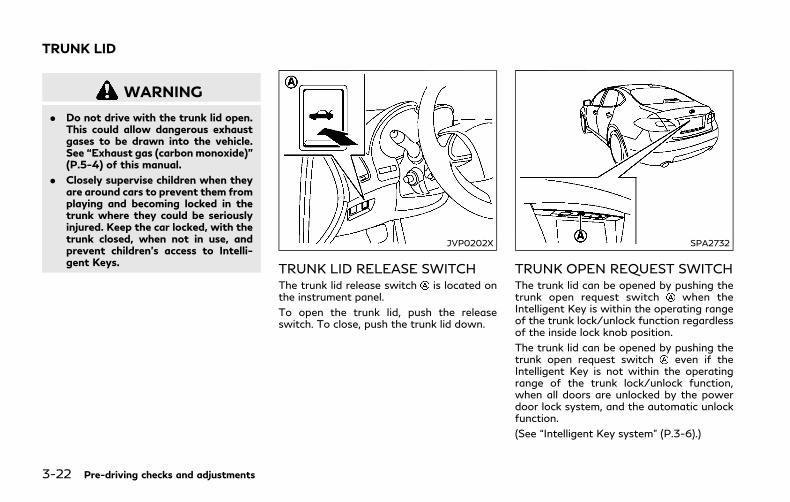
3-22 Pre-driving checks and adjustments
WARNING
. Do not drive with the trunk lid open.This could allow dangerous exhaustgases to be drawn into the vehicle.See “Exhaust gas (carbon monoxide)”(P.5-4) of this manual.
. Closely supervise children when theyare around cars to prevent them fromplaying and becoming locked in thetrunk where they could be seriouslyinjured. Keep the car locked, with thetrunk closed, when not in use, andprevent children’s access to Intelli-gent Keys.
JVP0202X
TRUNK LID RELEASE SWITCHThe trunk lid release switch is located onthe instrument panel.
To open the trunk lid, push the releaseswitch. To close, push the trunk lid down.
SPA2732
TRUNK OPEN REQUEST SWITCHThe trunk lid can be opened by pushing thetrunk open request switch when theIntelligent Key is within the operating rangeof the trunk lock/unlock function regardlessof the inside lock knob position.
The trunk lid can be opened by pushing thetrunk open request switch even if theIntelligent Key is not within the operatingrange of the trunk lock/unlock function,when all doors are unlocked by the powerdoor lock system, and the automatic unlockfunction.
(See “Intelligent Key system” (P.3-6).)
TRUNK LID
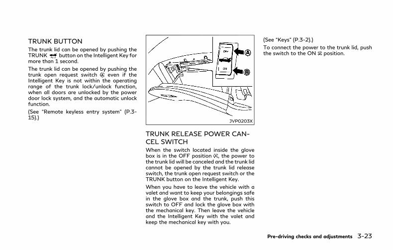
TRUNK BUTTONThe trunk lid can be opened by pushing theTRUNK button on the Intelligent Key formore than 1 second.
The trunk lid can be opened by pushing thetrunk open request switch even if theIntelligent Key is not within the operatingrange of the trunk lock/unlock function,when all doors are unlocked by the powerdoor lock system, and the automatic unlockfunction.
(See “Remote keyless entry system” (P.3-15).)
JVP0203X
TRUNK RELEASE POWER CAN-CEL SWITCHWhen the switch located inside the glovebox is in the OFF position , the power tothe trunk lid will be canceled and the trunk lidcannot be opened by the trunk lid releaseswitch, the trunk open request switch or theTRUNK button on the Intelligent Key.
When you have to leave the vehicle with avalet and want to keep your belongings safein the glove box and the trunk, push thisswitch to OFF and lock the glove box withthe mechanical key. Then leave the vehicleand the Intelligent Key with the valet andkeep the mechanical key with you.
(See “Keys” (P.3-2).)
To connect the power to the trunk lid, pushthe switch to the ON position.
Pre-driving checks and adjustments 3-23
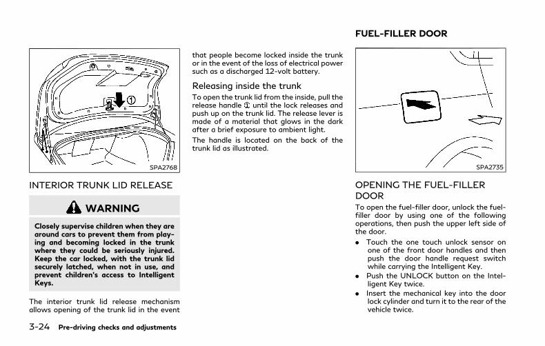
3-24 Pre-driving checks and adjustments
SPA2768
INTERIOR TRUNK LID RELEASE
WARNING
Closely supervise children when they arearound cars to prevent them from play-ing and becoming locked in the trunkwhere they could be seriously injured.Keep the car locked, with the trunk lidsecurely latched, when not in use, andprevent children’s access to IntelligentKeys.
The interior trunk lid release mechanismallows opening of the trunk lid in the event
that people become locked inside the trunkor in the event of the loss of electrical powersuch as a discharged 12-volt battery.
Releasing inside the trunkTo open the trunk lid from the inside, pull therelease handle until the lock releases andpush up on the trunk lid. The release lever ismade of a material that glows in the darkafter a brief exposure to ambient light.
The handle is located on the back of thetrunk lid as illustrated.
SPA2735
OPENING THE FUEL-FILLERDOORTo open the fuel-filler door, unlock the fuel-filler door by using one of the followingoperations, then push the upper left side ofthe door.
. Touch the one touch unlock sensor onone of the front door handles and thenpush the door handle request switchwhile carrying the Intelligent Key.
. Push the UNLOCK button on the Intel-ligent Key twice.
. Insert the mechanical key into the doorlock cylinder and turn it to the rear of thevehicle twice.
FUEL-FILLER DOOR
. Push the power door lock switch to theUNLOCK position.
To lock, close the fuel-filler door securelyand lock all doors by operating the doorhandle request switch, the LOCK button onthe Intelligent Key, the mechanical key or thepower door lock switch.
FUEL-FILLER CAP
WARNING
. Gasoline is extremely flammable andhighly explosive under certain condi-tions. You could be burned or ser-iously injured if it is misused ormishandled. Always stop theINFINITI Direct Response Hybrid®
System and do not smoke or allowopen flames or sparks near the ve-hicle when refueling.
. Do not attempt to top off the fueltank after the fuel pump nozzle shutsoff automatically. Continued refuel-ingmay cause fuel overflow, resultingin fuel spray and possibly a fire.
. Use only an original equipment typefuel-filler cap as a replacement. It hasa built-in safety valve needed forproper operation of the fuel systemand emission control system. An in-
correct cap can result in a seriousmalfunction and possible injury. Itcould also cause the MalfunctionIndicator Light (MIL) to come on.
. Never pour fuel into the throttle bodyto attempt to start your vehicle.
. Do not fill a portable fuel container inthe vehicle or trailer. Static electricitycan cause an explosion of flammableliquid, vapor or gas in any vehicle ortrailer. To reduce the risk of seriousinjury or death when filling portablefuel containers:
— Always place the container on theground when filling.
— Do not use electronic deviceswhen filling.
— Keep the pump nozzle in contactwith the container while you arefilling it.
— Use only approved portable fuelcontainers for flammable liquid.
CAUTION
. If fuel is spilled on the vehicle body,flush it away with water to avoidpaint damage.
. Failure to tighten the fuel-filler capproperly may cause the Malfunc-tion Indicator Light (MIL) to illumi-nate. If the light illuminatesbecause the fuel-filler cap is loose ormissing, tighten or install the cap andcontinue to drive the vehicle. Thelight should turn off after a fewdriving trips. If the light doesnot turn off after a few driving trips,have the vehicle inspected. It isrecommended you visit an INFINITIretailer for this service.
. The Loose Fuel Cap warning willappear if the fuel-filler cap is notproperly tightened. It may take a fewdriving trips for the warning to bedisplayed. Failure to tighten the fuel-filler cap properly after the LooseFuel Cap warning appears may causethe Malfunction Indicator Light(MIL) to illuminate.
. For additional information, see “Mal-function Indicator Light (MIL)” (P.2-16).
Pre-driving checks and adjustments 3-25
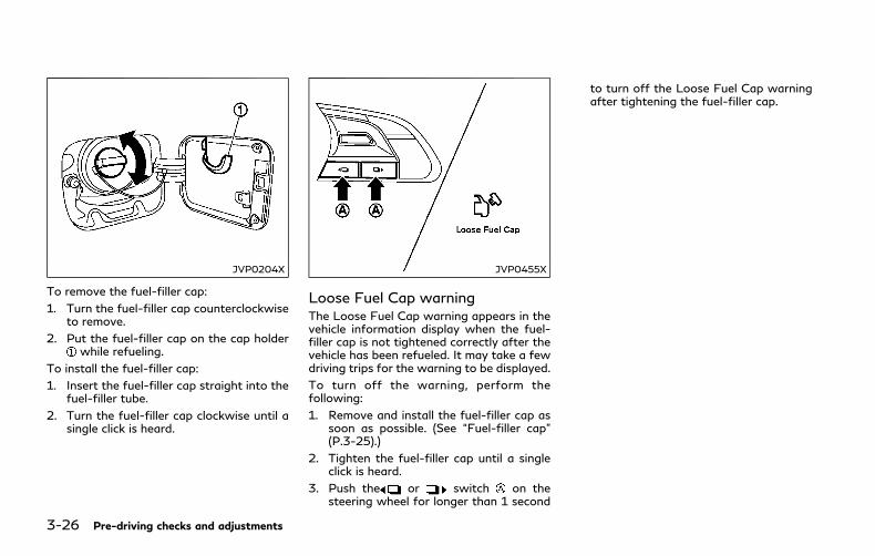
3-26 Pre-driving checks and adjustments
JVP0204X
To remove the fuel-filler cap:
1. Turn the fuel-filler cap counterclockwiseto remove.
2. Put the fuel-filler cap on the cap holderwhile refueling.
To install the fuel-filler cap:
1. Insert the fuel-filler cap straight into thefuel-filler tube.
2. Turn the fuel-filler cap clockwise until asingle click is heard.
JVP0455X
Loose Fuel Cap warningThe Loose Fuel Cap warning appears in thevehicle information display when the fuel-filler cap is not tightened correctly after thevehicle has been refueled. It may take a fewdriving trips for the warning to be displayed.
To turn off the warning, perform thefollowing:
1. Remove and install the fuel-filler cap assoon as possible. (See “Fuel-filler cap”(P.3-25).)
2. Tighten the fuel-filler cap until a singleclick is heard.
3. Push the or switch on thesteering wheel for longer than 1 second
to turn off the Loose Fuel Cap warningafter tightening the fuel-filler cap.

WARNING
. Do not adjust the steering wheelwhile driving. You could lose controlof your vehicle and cause an accident.
. Do not adjust the steering wheel anycloser to you than is necessary forproper steering operation and com-fort. The driver’s air bag inflates withgreat force. If you are unrestrained,leaning forward, sitting sideways orout of position in any way, you are atgreater risk of injury or death in acrash. You may also receive serious orfatal injuries from the air bag if youare up against it when it inflates.Always sit back against the seatbackand as far away as practical from thesteering wheel. Always use the seatbelts.
JVP0205X
ELECTRIC OPERATION
Tilt or telescopic operationMove the switch to adjust the steeringwheel up or down, forward or rearward tothe desired position.
Entry/Exit function operation:
The automatic drive positioner system willmake the steering wheel move up automa-tically when the driver’s door is opened withthe ignition switch in the LOCK position.This lets the driver get into and out of theseat more easily.
For more information, see “Automatic drivepositioner” (P.3-30).
SPA2471
1. To block glare from the front, swingdown the sun visor .
Pre-driving checks and adjustments 3-27
TILT/TELESCOPIC STEERING SUN VISORS
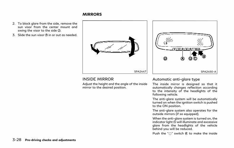
3-28 Pre-driving checks and adjustments
2. To block glare from the side, remove thesun visor from the center mount andswing the visor to the side .
3. Slide the sun visor in or out as needed.
SPA2447
INSIDE MIRRORAdjust the height and the angle of the insidemirror to the desired position.
SPA2450-A
Automatic anti-glare typeThe inside mirror is designed so that itautomatically changes reflection accordingto the intensity of the headlights of thefollowing vehicle.
The anti-glare system will be automaticallyturned on when the ignition switch is pushedto the ON position.
The anti-glare system also operates for theoutside mirrors (if so equipped).
When the anti-glare system is turned on, theindicator light will illuminate and excessiveglare from the headlights of the vehiclebehind you will be reduced.
Push the “*” switch to make the inside
MIRRORS

mirror operate normally. The indicator lightwill turn off. Push the “I” switch to turn thesystem on.
Do not allow any object to cover the sensorsor apply glass cleaner on them. Doing so
will reduce the sensitivity of the sensor,resulting in improper operation.
For the HomeLink® Universal Transceiveroperation, see “HomeLink® Universal Trans-ceiver” (P.2-59).
OUTSIDE MIRRORS
WARNING
Objects viewed in the outside mirror onthe passenger side are closer than theyappear. Be careful when moving to theright. Using only this mirror could causean accident. Use the inside mirror orglance over your shoulder to properlyjudge distances to other objects.
JVP0246X
Adjusting outside mirrorsThe outside mirror control switch is locatedon the driver’s armrest.
The outside mirror will operate only whenthe ignition switch is in the ACC or ONposition.
Move the switch right or left to select theright or left side mirror, then adjust using thecontrol switch .
Defrosting outside mirrorsThe outside mirrors will be heated when therear window defroster switch is operated.
SPA1829
Foldable outside mirrorsFold the outside mirror by pushing it towardthe rear of the vehicle.
Reverse tilt-down featureWhen backing up the vehicle, the right andleft outside mirrors will turn downwardautomatically to provide better rear visibility.
1. Push the ignition switch to the ONposition.
2. Move the shift lever to the R (Reverse)position.
3. Select the right or left side mirror byoperating the outside mirror controlswitch.
Pre-driving checks and adjustments 3-29
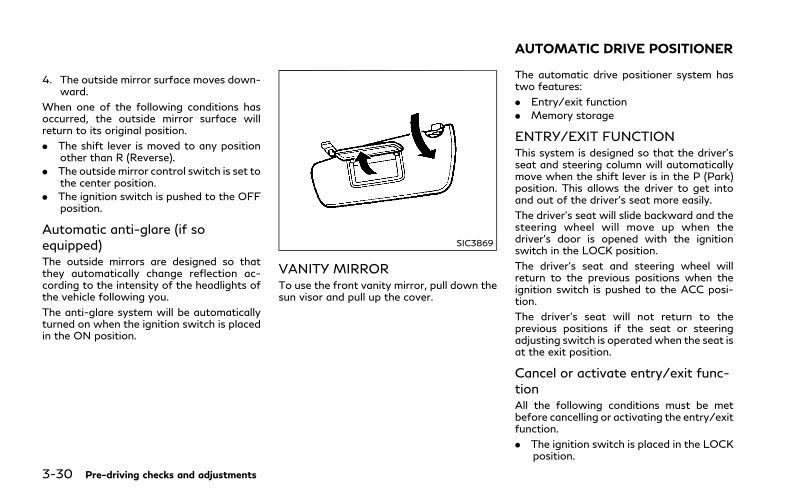
3-30 Pre-driving checks and adjustments
4. The outside mirror surface moves down-ward.
When one of the following conditions hasoccurred, the outside mirror surface willreturn to its original position.
. The shift lever is moved to any positionother than R (Reverse).
. The outside mirror control switch is set tothe center position.
. The ignition switch is pushed to the OFFposition.
Automatic anti-glare (if soequipped)The outside mirrors are designed so thatthey automatically change reflection ac-cording to the intensity of the headlights ofthe vehicle following you.
The anti-glare system will be automaticallyturned on when the ignition switch is placedin the ON position.
SIC3869
VANITY MIRRORTo use the front vanity mirror, pull down thesun visor and pull up the cover.
The automatic drive positioner system hastwo features:
. Entry/exit function
. Memory storage
ENTRY/EXIT FUNCTIONThis system is designed so that the driver’sseat and steering column will automaticallymove when the shift lever is in the P (Park)position. This allows the driver to get intoand out of the driver’s seat more easily.
The driver’s seat will slide backward and thesteering wheel will move up when thedriver’s door is opened with the ignitionswitch in the LOCK position.
The driver’s seat and steering wheel willreturn to the previous positions when theignition switch is pushed to the ACC posi-tion.
The driver’s seat will not return to theprevious positions if the seat or steeringadjusting switch is operatedwhen the seat isat the exit position.
Cancel or activate entry/exit func-tionAll the following conditions must be metbefore cancelling or activating the entry/exitfunction.
. The ignition switch is placed in the LOCKposition.
AUTOMATIC DRIVE POSITIONER
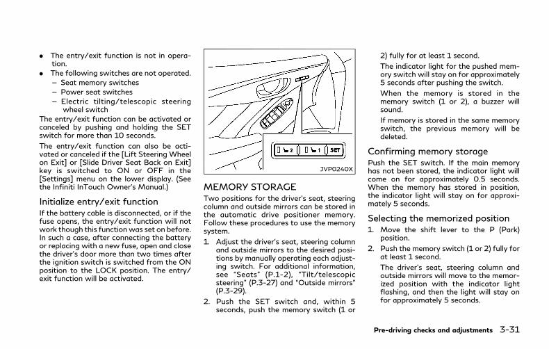
. The entry/exit function is not in opera-tion.
. The following switches are not operated.
— Seat memory switches
— Power seat switches
— Electric tilting/telescopic steeringwheel switch
The entry/exit function can be activated orcanceled by pushing and holding the SETswitch for more than 10 seconds.
The entry/exit function can also be acti-vated or canceled if the [Lift Steering Wheelon Exit] or [Slide Driver Seat Back on Exit]key is switched to ON or OFF in the[Settings] menu on the lower display. (Seethe Infiniti InTouch Owner’s Manual.)
Initialize entry/exit functionIf the battery cable is disconnected, or if thefuse opens, the entry/exit function will notwork though this function was set on before.In such a case, after connecting the batteryor replacing with a new fuse, open and closethe driver’s door more than two times afterthe ignition switch is switched from the ONposition to the LOCK position. The entry/exit function will be activated.
JVP0240X
MEMORY STORAGETwo positions for the driver’s seat, steeringcolumn and outside mirrors can be stored inthe automatic drive positioner memory.Follow these procedures to use the memorysystem.
1. Adjust the driver’s seat, steering columnand outside mirrors to the desired posi-tions by manually operating each adjust-ing switch. For additional information,see “Seats” (P.1-2), “Tilt/telescopicsteering” (P.3-27) and “Outside mirrors”(P.3-29).
2. Push the SET switch and, within 5seconds, push the memory switch (1 or
2) fully for at least 1 second.
The indicator light for the pushed mem-ory switch will stay on for approximately5 seconds after pushing the switch.
When the memory is stored in thememory switch (1 or 2), a buzzer willsound.
If memory is stored in the same memoryswitch, the previous memory will bedeleted.
Confirming memory storagePush the SET switch. If the main memoryhas not been stored, the indicator light willcome on for approximately 0.5 seconds.When the memory has stored in position,the indicator light will stay on for approxi-mately 5 seconds.
Selecting the memorized position1. Move the shift lever to the P (Park)
position.
2. Push the memory switch (1 or 2) fully forat least 1 second.
The driver’s seat, steering column andoutside mirrors will move to the memor-ized position with the indicator lightflashing, and then the light will stay onfor approximately 5 seconds.
Pre-driving checks and adjustments 3-31

3-32 Pre-driving checks and adjustments
Linking log-in function to a storedmemory positionThe log-in function can be linked to a storedmemory position with the following proce-dure.
1. Place the ignition switch in the ONposition while carrying an IntelligentKey that was registered to the vehiclewith the log-in function. For more de-tails, see “Log-in function” (P.3-15).
2. Adjust the position of the driver’s seat,steering column and outside mirrorsmanually. See “Seats” (P.1-2), “Tilt/tele-scopic steering” (P.3-27) and “Outsidemirrors” (P.3-29).
3. Place the ignition switch in the OFFposition.
The next time you log in (selecting the useron the display) after placing the ignitionswitch in the ON position while carrying theIntelligent Key, the system will automaticallyadjust to the memorized driving position.
SYSTEM OPERATIONThe automatic drive positioner system willnot work or will stop operating under thefollowing conditions:
. When the vehicle speed is above 0 MPH(0 km/h) or 4 MPH (7 km/h) for somelimited functions such linking an Intelli-
gent Key to the vehicle when the powersource is turned on from off or during theExit function.
. When any of the memory switches arepushed while the automatic drive posi-tioner is operating.
. When the adjusting switch for the dri-ver’s seat and steering column is turnedonwhile the automatic drive positioner isoperating.
. When the seat has already been movedto the memorized position.
. When no seat position is stored in thememory switch.
. When the shift lever is moved from the P(Park) position to any other position.
4 Monitor, climate, audio, phone and voice re-cognition systems
Infiniti InTouch Owner’s Manual .................................. 4-2
Ventilators ........................................................................... 4-2
Antenna................................................................................ 4-3
Window antenna.......................................................... 4-3
Satellite antenna ........................................................ 4-3
Car phone or CB radio .................................................... 4-3

4-2 Monitor, climate, audio, phone and voice recognition systems
Refer to the Infiniti InTouchOwner’sManualthat includes the following information.
. Infiniti InTouch Services
. Navigation system
. Audio system
. Bluetooth® Hands-Free Phone system
. Heater and air conditioner
. Viewing information
. Other settings
. Voice recognition
. Monitor system
. Meter settings
. General system information JVH0510X
Center ventilators
JVH0511X
Side ventilators
JVH0574X
Rear ventilatorsOpen or close, and adjust the air flowdirection of ventilators.
: This symbol indicates that the ventilatorsare closed.
: This symbol indicates that the ventilatorsare open.
INFINITI INTOUCH OWNER’S MANUAL VENTILATORS

WINDOW ANTENNAThe antenna pattern is printed inside therear window.
CAUTION
. Do not place metalized film near therear window glass or attach anymetal parts to it. This may cause poorreception or noise.
. When cleaning the inside of the rearwindow, be careful not to scratch ordamage the rear window antenna.Lightly wipe along the antenna witha dampened soft cloth.
JVH0641X
SATELLITE ANTENNAThere is a satellite antenna on the rear partof the vehicle roof.
A buildup of ice on the satellite radioantenna can affect satellite radio perfor-mance. Remove the ice to restore satelliteradio reception.
When installing a car phone or a CB radio inyour vehicle, be sure to observe the follow-ing cautions, otherwise the new equipmentmay adversely affect the electronic controlmodules and electronic control system har-ness.
WARNING
. A cellular phone should not be usedfor any purpose while driving so fullattention may be given to vehicleoperation. Some jurisdictions prohibitthe use of cellular phones whiledriving.
. If you must make a call while yourvehicle is in motion, the hands-freecellular phone operational mode (if soequipped) is highly recommended.Exercise extreme caution at all timesso full attention may be given tovehicle operation.
. If a conversation in a moving vehiclerequires you to take notes, pull offthe road to a safe location and stopyour vehicle before doing so.
Monitor, climate, audio, phone and voice recognition systems 4-3
ANTENNA CAR PHONE OR CB RADIO

4-4 Monitor, climate, audio, phone and voice recognition systems
CAUTION
. Keep the antenna as far away aspossible from the electronic controlmodules.
. Keep the antenna wire more than 8 in(20 cm) away from the electroniccontrol system harness. Do not routethe antennawire next to any harness.
. Adjust the antenna standing-waveratio as recommended by the manu-facturer.
. Connect the ground wire from the CBradio chassis to the body.
. For details, it is recommended youvisit an INFINITI retailer.

5 Starting and driving
Precautions when starting and driving ....................... 5-4
Exhaust gas (carbon monoxide) .............................. 5-4
Three-way catalyst ..................................................... 5-5
Tire Pressure Monitoring System (TPMS)............ 5-5
Avoiding collision and rollover ................................. 5-9
Off-road recovery ....................................................... 5-9
Rapid air pressure loss ............................................... 5-9
Drinking alcohol/drugs and driving ...................... 5-10
Intelligent All-Wheel Drive (AWD) drivingsafety precautions (AWD models) ........................ 5-10
Push-button ignition switch......................................... 5-11
Operating range for hybrid systemstart function .............................................................. 5-11
Push-button ignition switch operation ............... 5-12
Push-button ignition switch positions................. 5-12
Emergency hybrid system shut off ....................... 5-13
Intelligent Key battery discharge .......................... 5-13
Before starting the INFINITI Direct ResponseHybrid® System................................................................ 5-14
Starting the INFINITI Direct ResponseHybrid® System................................................................ 5-14
Remote start ............................................................... 5-15
Driving the vehicle ........................................................... 5-15
Automatic transmission ........................................... 5-15
Parking brake .................................................................. 5-20
INFINITI Drive Mode Selector .................................... 5-21
STANDARD mode ................................................... 5-21
SPORT mode ............................................................ 5-21
SNOW mode ............................................................. 5-21
ECO mode ................................................................. 5-21
PERSONAL mode ................................................... 5-23
Active Lane Control (if so equipped) ........................ 5-24
Active Lane Control operation ............................ 5-26
Turning Active Lane Control ON/OFF ............. 5-27
How to enable/disable ActiveLane Control ............................................................. 5-28
Active Lane Control limitations ........................... 5-29
System temporarily unavailable.......................... 5-30
System malfunction ............................................... 5-30
System maintenance ............................................... 5-31
Lane Departure Warning (LDW)/Lane DeparturePrevention (LDP) (if so equipped).............................. 5-32
LDW system operation .......................................... 5-33
How to enable/disable the LDW system ......... 5-34
LDP system operation............................................ 5-34
Turning the LDP system ON/OFF..................... 5-35
How to enable/disable the LDP system........... 5-36
LDW/LDP system limitations.............................. 5-36
System temporarily unavailable........................... 5-37
System malfunction ................................................ 5-38
System maintenance ................................................. 5-38
Blind Spot Warning (BSW) ........................................... 5-39
BSW system operation ............................................ 5-41
How to enable/disable the BSW system ........... 5-41
BSW system limitations ........................................... 5-41
BSW driving situations............................................. 5-42
System temporarily unavailable............................. 5-45
System malfunction................................................... 5-45
System maintenance ................................................. 5-46
Blind Spot Intervention® (BSI) (if so equipped) ...... 5-47
BSI system operation............................................... 5-48
Turning the BSI system ON/OFF........................ 5-50
How to enable/disable the BSI system .............. 5-51
BSI system limitations .............................................. 5-51
BSI driving situations ................................................ 5-53
System temporarily unavailable............................. 5-57
System malfunction................................................... 5-58
System maintenance ................................................. 5-58
Back-up Collision Intervention (BCI) ......................... 5-59
BCI system operation ............................................... 5-61
Turning the BCI system ON/OFF ........................ 5-65
How to enable/disable the BCI system .............. 5-66
BCI system limitations.............................................. 5-67
System temporarily unavailable............................. 5-68
System malfunction................................................... 5-69
System maintenance ................................................. 5-69
Cruise control (if so equipped)..................................... 5-70
Precautions on cruise control ................................. 5-70
Cruise control operations ...................................... 5-71
Intelligent Cruise Control (ICC) (if so equipped) .... 5-72
How to select the cruise control mode ............. 5-74
Vehicle-to-vehicle distance control mode ........ 5-74
Conventional (fixed speed) cruisecontrol mode ............................................................. 5-89
Distance Control Assist (DCA) (if so equipped) ..... 5-93
DCA system operation ........................................... 5-95
Turning the DCA system ON/OFF .................... 5-98
How to enable/disable the DCA system .......... 5-99
DCA system display and indicators .................... 5-99
DCA system limitations....................................... 5-100
System temporarily unavailable........................ 5-102
System malfunction ............................................. 5-103
Sensor maintenance ............................................. 5-103
Forward Emergency Braking (FEB) ....................... 5-104
FEB system operation ......................................... 5-105
Turning the FEB system ON/OFF .................. 5-107
FEB system limitations ....................................... 5-108
System temporarily unavailable........................ 5-110
System malfunction .............................................. 5-111
System maintenance ............................................. 5-111
Predictive Forward CollisionWarning (PFCW) .......................................................... 5-112
PFCW system operation ..................................... 5-114
Turning the PFCW system ON/OFF .............. 5-115
PFCW system limitations .................................... 5-117
System temporarily unavailable......................... 5-119
System malfunction ............................................. 5-120

System maintenance .............................................. 5-120
Break-in schedule .......................................................... 5-121
Fuel Efficient Driving Tips .......................................... 5-121
Increasing fuel economy.............................................. 5-122
Intelligent All-Wheel Drive (AWD) (ifso equipped) .................................................................... 5-123
Parking/parking on hills .............................................. 5-125
Power steering ............................................................... 5-126
Direct Adaptive Steering type.............................. 5-126
Brake system ................................................................. 5-128
Braking precautions ............................................... 5-128
Parking brake break-in ........................................... 5-129
Brake assist ..................................................................... 5-129
Brake assist ............................................................... 5-129
Anti-lock Braking System (ABS).......................... 5-129
Vehicle Dynamic Control (VDC) system ................ 5-130
Rise-up and build-up .............................................. 5-131
Brake force distribution ......................................... 5-131
Active trace control...................................................... 5-132
Hill Start Assist system .............................................. 5-134
Chassis control ............................................................. 5-134
Cold weather driving ................................................... 5-135
Freeing a frozen door lock .................................. 5-135
Antifreeze................................................................. 5-135
12-volt Battery ....................................................... 5-135
Draining of coolant water ................................... 5-135
Tire equipment ........................................................ 5-135
Special winter equipment .................................... 5-135
Driving on snow or ice.......................................... 5-135
Engine block heater (if so equipped) ............... 5-136
Active noise cancellation/Activesound enhancement ..................................................... 5-137
Active noise cancellation ..................................... 5-137
Active sound enhancement ................................. 5-137
5-4 Starting and driving
WARNING
. Do not leave children or adults whowould normally require the supportof others alone in your vehicle. Petsshould not be left alone either. Theycould accidentally injure themselvesor others through inadvertent opera-tion of the vehicle. Also, on hot,sunny days, temperatures in a closedvehicle could quickly become highenough to cause severe or possiblyfatal injuries to people or animals.
. Closely supervise children when theyare around cars to prevent them fromplaying and becoming locked in thetrunk where they could be seriouslyinjured. Keep the car locked, with therear seatback and trunk lid securelylatched when not in use, and preventchildren’s access to car keys.
EXHAUST GAS (carbon monoxide)
WARNING
. Do not breathe exhaust gases; theycontain colorless and odorless carbonmonoxide. Carbon monoxide is dan-gerous. It can cause unconsciousnessor death.
. If you suspect that exhaust fumes areentering the vehicle, drive with allwindows fully open, and have thevehicle inspected immediately.
. Do not run the engine in closed spacessuch as a garage.
. Do not park the vehicle with theINFINITI Direct Response Hybrid®
System running for any extendedlength of time.
. Keep the trunk lid closed while driv-ing, otherwise exhaust gases could bedrawn into the passenger compart-ment. If you must drive with thetrunk lid open, follow these precau-tions:
1) Open all the windows.
2) Set the air recirculation mode tooff and the fan control to high tocirculate the air.
. If electrical wiring or other cableconnections must pass to a trailerthrough the seal on the trunk lid orthe body, follow the manufacturer’srecommendation to prevent carbonmonoxide entry into the vehicle.
. The exhaust system and body shouldbe inspected by a qualified mechanicwhenever:
— The vehicle is raised for service.
— You suspect that exhaust fumesare entering into the passengercompartment.
— You notice a change in the soundof the exhaust system.
— You have had an accident invol-ving damage to the exhaust sys-tem, underbody, or rear of thevehicle.
PRECAUTIONS WHEN STARTINGAND DRIVING
THREE-WAY CATALYSTThe three-way catalyst is an emission con-trol device installed in the exhaust system.Exhaust gases in the three-way catalyst areburned at high temperatures to help reducepollutants.
WARNING
. The exhaust gas and the exhaustsystem are very hot. Keep people,animals or flammable materials awayfrom the exhaust system compo-nents.
. Do not stop or park the vehicle overflammable materials such as drygrass, waste paper or rags. Theymay ignite and cause a fire.
CAUTION
. Do not use leaded gasoline. Depositsfrom leaded gasoline seriously reducethe three-way catalyst’s ability tohelp reduce exhaust pollutants.
. Keep your engine tuned up. Malfunc-tions in the ignition, fuel injection, orelectrical systems can cause overrich
fuel flow into the three-way catalyst,causing it to overheat. Do not keepdriving if the engine misfires, or ifnoticeable loss of performance orother unusual operating conditionsare detected. Have the vehicle in-spected. It is recommended you visitan INFINITI retailer for this service.
. Avoid driving with an extremely lowfuel level. Running out of fuel couldcause the engine tomisfire, damagingthe three-way catalyst.
. Do not race the engine while warmingit up.
. Do not push or tow your vehicle tostart the hybrid system.
TIRE PRESSURE MONITORINGSYSTEM (TPMS)Each tire, including the spare (if provided),should be checked monthly when cold andinflated to the inflation pressure recom-mended by the vehicle manufacturer on thevehicle placard or tire inflation pressurelabel. (If your vehicle has tires of a differentsize than the size indicated on the vehicleplacard or tire inflation pressure label, youshould determine the proper tire inflationpressure for those tires.)
As an added safety feature, your vehicle hasbeen equipped with a Tire Pressure Mon-itoring System (TPMS) that illuminates a lowtire pressure telltale when one or more ofyour tires is significantly under-inflated.Accordingly, when the low tire pressuretelltale illuminates, you should stop andcheck your tires as soon as possible, andinflate them to the proper pressure. Drivingon a significantly under-inflated tire causesthe tire to overheat and can lead to tirefailure. Under-inflation also reduces fuelefficiency and tire tread life, and may affectthe vehicle’s handling and stopping ability.
If the vehicle is being drivenwith one or moreflat tires, the low tire pressure warning lightwill illuminate continuously and a chime willsound for 10 seconds. The “Flat Tire - Visitdealer” warning will also appear in thevehicle information display. The chime willonly sound at the first indication of a flat tire,and the warning light will illuminate con-tinuously. When the flat tire warning isactivated, it is recommended you have thesystem reset and the tire checked andreplaced if necessary by an INFINITI retailer.Even if the tire is inflated to the specifiedCOLD tire pressure, the warning light willcontinue to illuminate until the system isreset. Your vehicle can be driven for a limitedtime on a flat tire. See “Run-flat tires” (P.8-34).
Starting and driving 5-5
5-6 Starting and driving
Please note that the TPMS is not a sub-stitute for proper tire maintenance, and it isthe driver’s responsibility to maintain correcttire pressure, even if under-inflation has notreached the level to trigger illumination ofthe TPMS low tire pressure telltale.
Your vehicle has also been equipped with aTPMS malfunction indicator to indicatewhen the system is not operating properly.The TPMS malfunction indicator is com-bined with the low tire pressure telltale.When the system detects a malfunction, thetelltale will flash for approximately oneminute and then remain continuously illumi-nated. This sequence will continue uponsubsequent vehicle start-ups as long as themalfunction exists. When the malfunctionindicator is illuminated, the system may notbe able to detect or signal low tire pressureas intended. TPMS malfunctions may occurfor a variety of reasons, including theinstallation of replacement or alternate tiresor wheels on the vehicle that prevent theTPMS from functioning properly. Alwayscheck the TPMS malfunction telltale afterreplacing one or more tires or wheels on yourvehicle to ensure that the replacement oralternate tires and wheels allow the TPMSto continue to function properly.
Additional information. The TPMS will activate only when the
vehicle is driven at speeds above 16MPH (25 km/h). Also, this system maynot detect a sudden drop in tire pressure(for example a flat tire while driving).
. The low tire pressure warning light doesnot automatically turn off when the tirepressure is adjusted. After the tire isinflated to the recommended pressure,the vehicle must be driven at speedsabove 16MPH (25 km/h) to activate theTPMS and turn off the low tire pressurewarning light. Use a tire pressure gaugeto check the tire pressure.
. The “Tire Pressure Low - Add Air”warning appears in the vehicle informa-tion display when the low tire pressurewarning light is illuminated and low tirepressure is detected. The “Tire PressureLow - Add Air” warning turns off whenthe low tire pressure warning light turnsoff.
The “Tire Pressure Low - Add Air”warning does not appear if the low tirepressure warning light illuminates toindicate a TPMS malfunction.
. The “Flat Tire - Visit dealer” warningappears in the vehicle information dis-play when the low tire pressure warninglight is illuminated and one or more flat
tires are detected.
. Tire pressure rises and falls depending onthe heat caused by the vehicle’s opera-tion and the outside temperature. Do notreduce the tire pressure after drivingbecause the tire pressure rises afterdriving. Low outside temperature canlower the temperature of the air insidethe tire which can cause a lower tireinflation pressure. This may cause thelow tire pressure warning light to illumi-nate. If the warning light illuminates inlow ambient temperature, check the tirepressure for all four tires.
. You can also check the pressure of alltires in the vehicle information display.(See “Vehicle information display” (P.2-18).)
. After the ignition switch is placed in theON position, it may take a period of timefor the tire pressure to be displayedwhilethe vehicle is driven. Depending on theradio wave circumstance, tire pressuremay not correctly be displayed.
For additional information, see “Low tirepressure warning light” (P.2-12) and “TirePressure Monitoring System (TPMS)” (P.6-3).
WARNING
. Radio waves could adversely affectelectric medical equipment. Thosewho use a pacemaker should contactthe electric medical equipment man-ufacturer for the possible influencesbefore use.
. If the low tire pressure warning lightilluminates while driving, avoid sud-den steering maneuvers or abruptbraking, reduce vehicle speed, pulloff the road to a safe location andstop the vehicle as soon as possible.Driving with under-inflated tires maypermanently damage the tires andincrease the likelihood of tire failure.Serious vehicle damage could occurand may lead to an accident andcould result in serious personal injury.Check the tire pressure for all fourtires. Adjust the tire pressure to therecommended COLD tire pressureshown on the Tire and LoadingInformation label to turn the low tirepressure warning light OFF. If thelight still illuminates while drivingafter adjusting the tire pressure, atire may be flat or the TPMS may bemalfunctioning. If no tire is flat andall tires are properly inflated, it is
recommended you consult anINFINITI retailer.
. Although you can continue drivingwith a punctured run-flat tire, re-member that vehicle handling stabi-lity is reduced, which could lead to anaccident and personal injury. Also,driving a long distance at high speedsmay damage the tires.
. Do not drive at speeds above 50MPH (80 km/h) and do not drivemore than approximately 93 miles(150 km) with a punctured run-flattire. The actual distance the vehiclecan be driven on a flat tire depends onoutside temperature, vehicle load,road conditions and other factors.
. If you detect any unusual sounds orvibrations while driving with a punc-tured run-flat tire, pull off the roadto a safe location and stop the vehicleas soon as possible. The tire may beseriously damaged and need to bereplaced.
. When a wheel is replaced, the TPMSwill not function and the low tirepressure warning light will flash forapproximately 1 minute. The light willremain on after 1 minute. Have yourtires replaced and/or TPMS systemreset as soon as possible. It is recom-
mended you visit an INFINITI retailerfor these services.
. Replacing tires with those not origin-ally specified by INFINITI could affectthe proper operation of the TPMS.
. Do not inject any tire liquid or aerosoltire sealant into the tires, as this maycause a malfunction of the tire pres-sure sensors.
CAUTION
. The TPMS may not function properlywhen the wheels are equipped withtire chains or the wheels are buried insnow.
. Do not place metalized film or anymetal parts (antenna, etc.) on thewindows. This may cause poor recep-tion of the signals from the tirepressure sensors, and the TPMS willnot function properly.
Some devices and transmitters may tem-porarily interfere with the operation of theTPMS and cause the low tire pressurewarning light to illuminate. Some examplesare:
Starting and driving 5-7
5-8 Starting and driving
. Facilities or electric devices using similarradio frequencies are near the vehicle.
. If a transmitter set to similar frequenciesis being used in or near the vehicle.
. If a computer (or similar equipment) or aDC/AC converter is being used in or nearthe vehicle.
Low tire pressure warning light may illumi-nate in the following cases.
. If the vehicle is equipped with a wheeland tire without TPMS.
. If the TPMS has been replaced and the IDhas not been registered.
. If the wheel is not originally specified byINFINITI.
FCC Notice:
For USA:
This device complies with Part 15 of theFCC Rules. Operation is subject to thefollowing two conditions: (1) This devicemay not cause harmful interference, and (2)this device must accept any interferencereceived, including interference that maycause undesired operation.
NOTE:
Changes or modifications not expresslyapproved by the party responsible forcompliance could void the user’s authorityto operate the equipment.
For Canada:
This device complies with Industry Canadalicence-exempt RSS standard(s). Operationis subject to the following two conditions:
1. This device may not cause interference,and
2. This device must accept any interfer-ence, include interference that maycause undesired operation of the device.
TPMS with Tire Inflation IndicatorWhen adding air to an under-inflated tire,the TPMS with Tire Inflation Indicatorprovides visual and audible signals outsidethe vehicle to help you inflate the tires to therecommended COLD tire pressure.
Vehicle set-up:
1. Park the vehicle in a safe and level place.
2. Apply the parking brake and place theshift lever in the P (Park) position.
3. Place the ignition switch in the ONposition. Do not start the hybrid system.
Operation:
1. Add air to the tire.
2. After a few seconds, the hazard indica-tors will start flashing.
3. When the designated pressure isreached, the horn beeps once and thehazard indicators stop flashing.
4. Perform the above steps for each tire.
. If the tire is over-inflated more thanapproximately 4 psi (30 kPa), the hornbeeps and the hazard indicators flash 3times. To correct the pressure, push thecore of the valve stem on the tire brieflyto release pressure. When the pressurereaches the designated pressure, thehorn beeps once.
. If the hazard indicator does not flashwithin approximately 15 seconds afterstarting to inflate the tire, it indicatesthat the Tire Inflation Indicator is notoperating.
. The TPMS will not activate the TireInflation Indicator under the followingconditions:
— If there is interference from an ex-ternal device or transmitter
— The air pressure from the inflationdevice such as those using a powersocket is not sufficient to inflate thetire
— If an electrical equipment is being usedin or near the vehicle
— There is a malfunction in the TPMSsystem
— There is a malfunction in the horn orhazard indicators
. If the Tire Inflation Indicator does notoperate due to TPMS interference, move
the vehicle about 3 ft (1 m) backward orforward and try again.
If the Tire Inflation Indicator is not working,use a tire pressure gauge.
AVOIDING COLLISION ANDROLLOVER
WARNING
Failure to operate this vehicle in a safeand prudent manner may result in loss ofcontrol or an accident.
Be alert and drive defensively at all times.Obey all traffic regulations. Avoid excessivespeed, high speed cornering, or suddensteering maneuvers, because these drivingpractices could cause you to lose control ofyour vehicle. As with any vehicle, a loss ofcontrol could result in a collision with othervehicles or objects, or cause the vehicle torollover, particularly if the loss of controlcauses the vehicle to slide sideways. Beattentive at all times, and avoid driving whentired. Never drive when under the influenceof alcohol or drugs (including prescription orover-the-counter drugs which may causedrowsiness). Always wear your seat belt asoutlined in the “Seat belts” (P.1-9) of thismanual, and also instruct your passengers to
do so.
Seat belts help reduce the risk of injury incollisions and rollovers. In a rollover crash,an unbelted or improperly belted person issignificantly more likely to be injured orkilled than a person properly wearing a seatbelt.
OFF-ROAD RECOVERYIf driving the right side or left side wheelsmay unintentionally leave the road surface.Maintain control of the vehicle by followingthe procedure below. Please note that thisprocedure is only a general guide. The vehiclemust be driven as appropriate based on theconditions of the vehicle, road and traffic.
1. Remain calm and do not overreact.
2. Do not apply the brakes.
3. Maintain a firm grip on the steeringwheel with both hands and try to holda straight course.
4. When appropriate, slowly release theaccelerator pedal to gradually slow thevehicle.
5. If there is nothing in the way, steer thevehicle to follow the road while thevehicle speed is reduced. Do not attemptto drive the vehicle back onto the roadsurface until vehicle speed is reduced.
6. When it is safe to do so, gradually turnthe steering wheel until both tires returnto the road surface. When all tires are onthe road surface, steer the vehicle to stayin the appropriate driving lane.. If you decide that it is not safe to
return the vehicle to the road surfacebased on vehicle, road or trafficconditions, gradually slow the vehicleto a stop in a safe place off the road.
RAPID AIR PRESSURE LOSSRapid air pressure loss or a “blow-out” canoccur if the tire is punctured or is damageddue to hitting a curb or pothole. Rapid airpressure loss can also be caused by drivingon under-inflated tires.
Rapid air pressure loss can affect thehandling and stability of the vehicle, espe-cially at highway speeds.
Help prevent rapid air pressure loss bymaintaining the correct air pressure andvisually inspect the tires for wear anddamage. See “Wheels and tires” (P.8-28) ofthis manual.
If a tire rapidly loses air pressure or “blows-out” while driving maintain control of thevehicle by following the procedure below.Please note that this procedure is only ageneral guide. The vehicle must be driven asappropriate based on the conditions of the
Starting and driving 5-9

5-10 Starting and driving
vehicle, road and traffic.
WARNING
The following actions can increase thechance of losing control of the vehicle ifthere is a sudden loss of tire air pressure.Losing control of the vehicle may cause acollision and result in personal injury.
. The vehicle generally moves or pullsin the direction of the flat tire.
. Do not rapidly apply the brakes.
. Do not rapidly release the acceleratorpedal.
. Do not rapidly turn the steeringwheel.
1. Remain calm and do not overreact.
2. Maintain a firm grip on the steeringwheel with both hands and try to holda straight course.
3. When appropriate, slowly release theaccelerator pedal to gradually slow thevehicle.
4. Gradually steer the vehicle to a safelocation off the road and away fromtraffic if possible.
5. Lightly apply the brake pedal to gradu-ally stop the vehicle.
6. Turn on the hazard warning flashers andeither contact a roadside emergencyservice to change the tire or see “Jackingup the vehicle and replacing tires” (P.8-39) of this Owner’s Manual.
DRINKING ALCOHOL/DRUGSAND DRIVING
WARNING
Never drive under the influence of alco-hol or drugs. Alcohol in the bloodstreamreduces coordination, delays reactiontime and impairs judgement. Drivingafter drinking alcohol increases the like-lihood of being involved in an accidentinjuring yourself and others. Addition-ally, if you are injured in an accident,alcohol can increase the severity of theinjury.
INFINITI is committed to safe driving. How-ever, you must choose not to drive under theinfluence of alcohol. Every year thousands ofpeople are injured or killed in alcohol-relatedaccidents. Although the local laws vary onwhat is considered to be legally intoxicated,the fact is that alcohol affects all peopledifferently and most people underestimatethe effects of alcohol.
Remember, drinking and driving don’t mix!And that is true for drugs, too (over-the-counter, prescription, and illegal drugs).Don’t drive if your ability to operate yourvehicle is impaired by alcohol, drugs, or someother physical condition.
INTELLIGENT ALL-WHEELDRIVE (AWD) DRIVING SAFETYPRECAUTIONS (AWD models)
WARNING
. Do not drive beyond the performancecapability of the tires, even withIntelligent AWD engaged. Accelerat-ing quickly, sharp steering maneuversor sudden braking may cause loss ofcontrol.
. Always use tires of the same type,size, brand, construction (bias, bias-belted or radial), and tread patternon all four wheels. Install tire chainson the rear wheels when driving onslippery roads and drive carefully.
. This vehicle is not designed for off-road (rough road) use. Do not driveon sandy or muddy roads that tiresmay get stuck in.
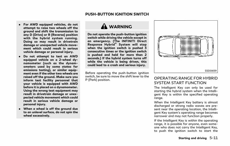
. For AWD equipped vehicles, do notattempt to raise two wheels off theground and shift the transmission toany D (Drive) or R (Reverse) positionwith the hybrid system running.Doing so may result in drivetraindamage or unexpected vehicle move-ment which could result in seriousvehicle damage or personal injury.
. Do not attempt to test an AWDequipped vehicle on a 2-wheel dy-namometer (such as the dynam-ometers used by some states foremissions testing), or similar equip-ment even if the other twowheels areraised off the ground. Make sure youinform test facility personnel thatyour vehicle is equipped with AWDbefore it is placed on a dynamometer.Using the wrong test equipment mayresult in drivetrain damage or unex-pected vehicle movement which couldresult in serious vehicle damage orpersonal injury.
. When a wheel is off the ground dueto an unlevel surface, do not spin thewheel excessively.
WARNING
Do not operate the push-button ignitionswitch while driving the vehicle except inan emergency. (The INFINITI DirectResponse Hybrid® System will stopwhen the ignition switch is pushed 3consecutive times or the ignition switchis pushed and held for more than 2seconds.) If the hybrid system turns offwhile the vehicle is being driven, thiscould lead to a crash and serious injury.
Before operating the push-button ignitionswitch, be sure to move the shift lever to theP (Park) position.
SSD0659
OPERATING RANGE FOR HYBRIDSYSTEM START FUNCTIONThe Intelligent Key can only be used forstarting the hybrid system when the Intelli-gent Key is within the specified operatingrange.
When the Intelligent Key battery is almostdischarged or strong radio waves are pre-sent near the operating location, the Intelli-gent Key system’s operating range becomesnarrower and may not function properly.
If the Intelligent Key is within the operatingrange, it is possible for anyone, even some-one who does not carry the Intelligent Key,to push the ignition switch to start the
Starting and driving 5-11
PUSH-BUTTON IGNITION SWITCH

5-12 Starting and driving
hybrid system.
. The trunk area is not included in theoperating range but the Intelligent Keymay function.
. If the Intelligent Key is placed on theinstrument panel, rear parcel shelf, insidethe glove box or door pocket, theIntelligent Key may not function.
. If the Intelligent Key is placed near thedoor or window outside the vehicle, theIntelligent Key may function.
CAUTION
When pressing the ignition to the OFFposition, make sure the button is notpressed twice. This may unintentionallyleave the vehicle in ACC or ON mode.This may discharge the 12-volt battery.
JVS0266X
PUSH-BUTTON IGNITIONSWITCH OPERATIONWhen the ignition switch is pushed withoutdepressing the brake pedal, the ignitionswitch position will change as follows:
. Push center once to change to ACC.
. Push center two times to change to ON.
. Push center three times to change toOFF. (No position illuminates.)
. Push center four times to return to ACC.
. Open or close any door to return toLOCK during the OFF position.
If the ignition switch is pushed quickly or israpidly pushed twice, the hybrid system maynot start. If this occurs, put the shift lever in
the “P” (Park) position, and leave the ignitionswitch in the “OFF” position for one minute.Then depress the brake pedal and push theignition switch to “ON”.When the READY todrive indicator light illuminates, thevehicle can be driven.
The ignition lock is designed so that theignition switch position cannot be switchedto LOCK until the shift lever is moved to theP (Park) positon.
When the ignition switch cannot beswitched toward the LOCK position, movethe shift lever into the P (Park) position.
PUSH-BUTTON IGNITIONSWITCH POSITIONS
LOCK (Normal parking position)The ignition switch can only be locked in thisposition.
The ignition switch will be unlocked when itis pushed to the ACC position while carryingthe Intelligent Key.
ACC (Accessories)This position activates electrical accessoriessuch as the radio, when the hybrid system isnot running.

ON (Normal operating position)This position turns on the ignition systemand electrical accessories.
OFFThe hybrid system can be turned off in thisposition.
The ignition lock is designed so that theignition switch cannot be switched to theLOCK position until the shift lever is movedto the P (Park) position.
CAUTION
Do not leave the vehicle with the push-button ignition switch in ACC or ONpositions when the hybrid system is notrunning for an extended period. This candischarge the 12-volt battery.
EMERGENCY HYBRID SYSTEMSHUT OFFTo shut off the hybrid system in an emer-gency situation while driving, perform thefollowing procedure:
. Rapidly push the push-button ignitionswitch 3 consecutive times, in less than1.5 seconds, or
. Push and hold the push-button ignitionswitch for more than 2 seconds.
JVS0404X
INTELLIGENT KEY BATTERY DIS-CHARGEIf the battery of the Intelligent Key isdischarged, or environmental conditions in-terfere with the Intelligent Key operation,start the hybrid system according to thefollowing procedure:
1. Move the shift lever to the P (Park)position.
2. Firmly apply the foot brake.
3. Touch the ignition switch with theIntelligent Key as illustrated. (A chimewill sound.)
4. Push the ignition switchwhile depressing
Starting and driving 5-13
5-14 Starting and driving
the brake pedal within 10 seconds afterthe chime sounds. The hybrid system willstart.
After step 3 is performed, when the ignitionswitch is pushed without depressing thebrake pedal, the ignition switch position willchange to ACC.
NOTE:. When the ignition switch is pushed to
the ACC or ON position or the hybridsystem is started by the above proce-dures, the Intelligent Key battery dis-charge indicator appears in the vehicleinformation display even if the Intelli-gent Key is inside the vehicle. This is nota malfunction. To turn off the IntelligentKey battery discharge indicator, touchthe ignition switch with the IntelligentKey again.
. If the Intelligent Key battery dischargeindicator appears, replace the battery assoon as possible. (See “Intelligent Keybattery replacement” (P.8-21).)
. Make sure the area around the vehicle isclear.
. Check fluid levels such as engine oil,coolant, brake fluid and window washerfluid as frequently as possible, or at leastwhenever you refuel.
. Check that all windows and lights areclean.
. Visually inspect tires for their appearanceand condition. Also check tires for properinflation.
. Lock all doors.
. Position seat and adjust head restraints.
. Adjust inside and outside mirrors.
. Fasten seat belts and ask all passengersto do likewise.
. Check the operation of warning lightswhen the ignition switch is pushed to theON position. (See “Warning lights, in-dicator lights and audible reminders”(P.2-9).)
1. Apply the parking brake.
2. Move the shift lever to P (Park) position.
The INFINITI Direct Response Hybrid®
System is designed not to operate if theshift lever is not in the P (Park) position.
3. Depress the brake pedal and push theignition switch to start the hybrid sys-tem. The READY to drive indicator lightwill illuminate on the meter.
When starting the hybrid system at verylow outside temperatures, the READYto drive indicator light will flash and itmay take longer for the READY to driveindicator light to illuminate.
. The hybrid system may not start evenwith the READY to drive indicator lightilluminated. Once the READY to driveindicator light is illuminated you maybegin driving the vehicle.
. You may hear a sound in the enginecompartment when the brake pedal isdepressed with the hybrid system off.This does not indicate a problem.
NOTE:
Care should be taken to avoid situationsthat can lead to potential 12-volt batterydischarge and potential no-start conditionssuch as:1. Installation or extended use of electro-
nic accessories that consume 12-volt
BEFORE STARTING THE INFINITIDIRECT RESPONSE HYBRID® SYSTEM
STARTING THE INFINITI DIRECTRESPONSE HYBRID® SYSTEM

battery power when the hybrid systemis not running (Phone chargers, GPS,DVD players, etc.)
2. Vehicle is not driven regularly and/oronly driven short distances.
In these cases, the 12-volt battery mayneed to be charged to maintain 12-voltbattery health.
REMOTE STARTVehicles started with the remote enginestart function require the ignition switch tobe placed in the ON position before the shiftlever can be moved from the P (Park)position. To place the ignition switch in theON position, perform the following steps:
1. Make sure that the Intelligent Key is onyou.
2. Depress the brake pedal.
3. Push the ignition switch once to the ONposition.
For additional information about the remoteengine start function, see “Remote enginestart” (P.3-19).
AUTOMATIC TRANSMISSIONThe automatic transmission in your vehicle iselectronically controlled by a transmissioncontrol module to produce maximum effi-ciency and smooth operation.
Shown on the following pages are therecommended operating procedures for thistransmission. Follow these procedures formaximum vehicle performance and drivingenjoyment.
Starting the vehicleAfter starting the INFINITI Direct ResponseHybrid® System, fully depress the foot brakepedal and push the shift lever button beforeshifting the shift lever to the R (Reverse), N(Neutral), D (Drive) or Manual shift modeposition. Be sure the vehicle is fully stoppedbefore attempting to shift the shift lever.
This Automatic Transmission (AT) model isdesigned so that the foot brake pedal mustbe depressed before shifting from P (Park)to any drive position while the ignitionswitch is in the ON position.
The shift lever cannot be moved out of the P(Park) position and into any of the othergear positions if the ignition switch ispushed to the LOCK, OFF or ACC position.
1. Keep the foot brake pedal depressed andpush the shift lever button to shift into a
driving gear.
2. Release the parking brake and footbrake, then gradually start the vehicle inmotion.
WARNING
. Do not depress the accelerator pedalwhile shifting from P (Park) or N(Neutral) to R (Reverse), D (Drive) ormanual shift mode. Always depressthe brake pedal until shifting iscompleted. Failure to do so couldcause you to lose control and havean accident.
. Cold engine idle speed is high, so usecaution when shifting into a forwardor reverse gear before the engine haswarmed up.
. Never shift to either P (Park) or R(Reverse) position while the vehicle ismoving forward and P (Park) or D(Drive) position while the vehicle ismoving reversing. This could cause anaccident or damage the transmission.
. Do not downshift abruptly on slip-pery roads. This may cause a loss ofcontrol.
Starting and driving 5-15
DRIVING THE VEHICLE

5-16 Starting and driving
CAUTION
. To avoid possible damage to yourvehicle; when stopping the vehicle onan uphill grade, do not hold thevehicle by depressing the acceleratorpedal. The foot brake should be usedfor this purpose.
. Except in an emergency, do not shiftto the N (Neutral) position whiledriving. Coasting with the transmis-sion in the N (Neutral) position maycause serious damage to the trans-mission.
JVS0186X
Shift leverTo move the shift lever,
: Push the button while depressing thebrake pedal,
: Push the button,
: Just move the shift lever.
ShiftingAfter starting the hybrid system, fully de-press the brake pedal and shift the shift leverfrom P (Park) to R (Reverse), N (Neutral), D(Drive) or Manual shift mode position.
Push the button to shift into P (Park) or R(Reverse). All other positions can be selectedwithout pushing the button.
WARNING
Apply the parking brake if the shift leveris in any position while the hybrid systemis not running. Failure to do so couldcause the vehicle to move unexpectedlyor roll away and result in serious perso-nal injury or property damage.
CAUTION
Make sure the vehicle is completelystopped and the transmission is in theP (Park) position.
P (Park) position:
Use this position when the vehicle is parkedor when starting the hybrid system. Makesure the vehicle is completely stopped. Thebrake pedal must be depressed and the shiftlever button pushed in to move the shiftlever from the N (Neutral) position or anydrive position to the P (Park) position.Apply the parking brake. When parking ona hill, apply the parking brake first, thenmove the shift lever to the P (Park) position.

CAUTION
Use this position only when the vehicle iscompletely stopped.
R (Reverse):
Use this position to back up. Always be surethe vehicle is completely stopped beforeselecting the R (Reverse) position. The brakepedal must be depressed and the shift leverbutton pushed in to move the shift leverfrom the P (Park) position, the N (Neutral)position or any drive position to the R(Reverse) position.
N (Neutral):
Neither forward nor reverse gear is engaged.The hybrid system can be started in thisposition. You may shift to the N (Neutral)position and restart a stalled hybrid systemwhile the vehicle is moving.
D (Drive):
Use this position for all normal forwarddriving.
Manual shift modeWhen the shift lever is in the manual shiftgate, the transmission is ready for themanual shift mode. Shift ranges can beselected manually by moving the shift lever
up or down.
When shifting up, move the shift lever to the+ (up) side. The transmission shifts to thehigher range.
When shifting down, move the shift lever tothe − (down) side. The transmission shifts tothe lower range.
When canceling the manual shift mode,return the shift lever to the D (Drive)position. The transmission returns to thenormal driving mode.
In the manual shift mode, the shift range isdisplayed in the vehicle information display.
Shift ranges up or down one by one asfollows:
1M?/ 2M
?/ 3M
?/ 4M
?/ 5M
?/ 6M
?/ 7M
7M (7th):
Use this position for all normal forwarddriving at highway speeds.
6M (6th) and 5M (5th):
Use these positions when driving up longslopes, or for engine braking when drivingdown long slopes.
4M (4th), 3M (3rd) and 2M (2nd):
Use these positions for hill climbing or enginebraking on downhill grades.
1M (1st):
Use this position when climbing steep hillsslowly or driving slowly through deep snow,or for maximum engine braking on steepdownhill grades.
. Remember not to drive at high speeds forextended periods of time in lower than7th gear. This reduces fuel economy.
. Moving the shift lever rapidly to the sameside twice will shift the ranges in succes-sion.
. In the manual shift mode, the transmis-sion may not shift to the selected gearor may automatically shift to the othergear. This helps maintain driving per-formance and reduces the chance ofvehicle damage or loss of control.
. When the transmission does not shift tothe selected gear, the Automatic Trans-mission (AT) position indicator (in thevehicle information display) will blinkand the buzzer will sound.
. In the manual shift mode, the transmis-sion automatically shifts down to 1stgear before the vehicle comes to a stop.When accelerating again, it is necessaryto shift up to the desired range.
Accelerator downshift — In D (Drive)position —
Starting and driving 5-17

5-18 Starting and driving
For passing or hill climbing, fully depress theaccelerator pedal to the floor. This shifts thetransmission down into the lower gear,depending on the vehicle speed.
Fail-safeWhen the fail-safe operation occurs, notethat the transmission will be locked in any ofthe forward gears according to the condi-tion.
If the vehicle is driven under extremeconditions, such as excessive wheel spinningand subsequent hard braking, the fail-safesystem may be activated. This will occureven if all electrical circuits are functioningproperly. In this case, push the ignitionswitch to the OFF position and wait for 3seconds. Then push the ignition switch backto the ON position. The vehicle shouldreturn to its normal operating condition. Ifit does not return to its normal operatingcondition, have the transmission checkedand repaired, if necessary. It is recom-mended you visit an INFINITI retailer forthis service.
JVS0188X
Shift lock releaseIf the 12-volt battery charge is low ordischarged, the shift lever may not be movedfrom the P (Park) position even with thebrake pedal depressed and the shift leverbutton pushed.
To move the shift lever, perform the follow-ing procedure:
1. Push the ignition switch to the OFF orLOCK position.
2. Apply the parking brake.
3. Remove the shift lock cover using asuitable tool.
4. Push down the shift lock usingmechanical key as illustrated.
5. Push the shift lever button and movethe shift lever to N (Neutral) positionwhile holding down the shift lock.
If the lever cannot be moved out of P (Park),have the automatic transmission systemchecked as soon as possible. It is recom-mended you visit an INFINITI retailer for thisservice.
Adaptive Shift Control (ASC)The adaptive shift control system automati-cally operates when the transmission is inthe D (Drive) position and selects an appro-priate gear depending on the road conditionssuch as uphill, downhill or curving roads.
Control on uphill and curving roads:
A low gear is maintained that suits thedegree of the slope or curve to allow smoothdriving with a small number of shifts.
Control on downhill roads:
The adaptive shift control system shifts to alow gear that suits the degree of the slope toreduce the number of times that the brakemust be used.
Control on winding roads:
A low gear is maintained on continuouscurves that involve repeated accelerationand deceleration, so that smooth accelera-tion is available instantly when the accel-erator pedal is depressed.
NOTE:. Adaptive shift control may not operate
when the transmission oil temperatureis low immediately after the start ofdriving or when it is very hot.
. During some driving situations, hardbraking for example, the adaptive shiftcontrol may automatically operate. Thetransmission may automatically shift toa lower gear for re-acceleration. Thisincreases engine speed but not vehiclespeed. Vehicle speed is controlled by theaccelerator pedal when the vehicle is inthe Adaptive shift control mode.
. When the adaptive shift control oper-ates, the transmission sometimes main-tains a lower gear for a longer period oftime than when adaptive shift control isnot operating. Engine speed will behigher for a specific vehicle speed whileASC system is operating than when ASCis not operating.
NAVI Shift ControlNAVI Shift Control automatically adjusts theAutomatic Transmission (AT) gear positionin certain situations based on road informa-tion from the navigation system.
When the navigation system detects thatthe vehicle is approaching a curved road,NAVI Shift Control will adjust the gear
position if needed to help the driver runthrough the curve smoothly.
Precaution on NAVI Shift Control:
. The NAVI Shift Control does not providesteering input or automated driving on acurve. It is not a speed limit supportsystem and will not modify your speedaccording to local speed limits.
. The NAVI Shift Control is a convenientsystem intended to help the vehicle movethrough a curve smoothly. However, thedriver must always drive safely and usethe brake pedal if needed.
. The NAVI Shift Control may be delayedor not operate properly in the followingsituations, because this function uses theroad information provided by the navi-gation system.
— When the navigation system cannotaccurately detect the location of thevehicle.
— When the vehicle is driving on a road-way that is not recognized by thenavigation system.
— When the actual roadway differs fromthe map information on the naviga-tion system due to road construction,traffic lane obstructions, etc.
. The NAVI Shift Control may not operateproperly in the following situations:
— If the vehicle’s transmission, engine,hybrid system and/or navigation sys-tem, and/or GPS is malfunctioning.
— If the vehicle speed is higher than 74MPH (120 km/h) or lower than 37MPH (60 km/h) and/or transmissiongear is outside the operating range ofthe system.
— When the vehicle is driving on a free-way.
— When the vehicle is driving on a gentlecurve
— When the vehicle is driving with theshift lever except in the D (Drive)position.
Starting and driving 5-19

5-20 Starting and driving
JVS0246X
How to enable/disable the NAVI ShiftControl:
Perform the following steps to enable ordisable the NAVI Shift Control.
1. Push the MENU button and touch[Settings] on the lower display.
2. Touch [Drive Mode Enhancement].
3. Touch [Navi Shift Control] and select theON (enabled) or OFF (disabled).
WARNING
. Be sure the parking brake is fullyreleased before driving. Failure to doso can cause brake failure and lead toan accident.
. Do not release the parking brakefrom outside the vehicle.
. Do not use the gear shift in place ofthe parking brake. When parking, besure the parking brake is fully en-gaged.
. To help avoid risk of injury or deaththrough unintended operation of thevehicle and/or its systems, do notleave children, people who require theassistance of others or pets unat-tended in your vehicle. Additionally,the temperature inside a closed ve-hicle on a warm day can quicklybecome high enough to cause a sig-nificant risk of injury or death topeople and pets.
SPA2331
To apply: Fully depress the parking brakepedal .
To release:
1. Firmly apply the foot brake .
2. Depress the parking brake pedal andthe parking brake will be released.
3. Before driving, be sure the brakewarninglight goes out.
PARKING BRAKE
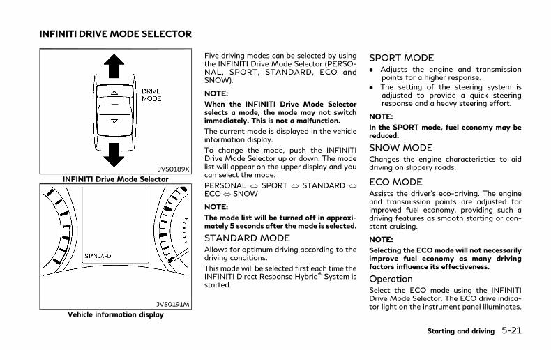
JVS0189X
INFINITI Drive Mode Selector
JVS0191M
Vehicle information display
Five driving modes can be selected by usingthe INFINITI Drive Mode Selector (PERSO-NAL, SPORT, STANDARD, ECO andSNOW).
NOTE:
When the INFINITI Drive Mode Selectorselects a mode, the mode may not switchimmediately. This is not a malfunction.
The current mode is displayed in the vehicleinformation display.
To change the mode, push the INFINITIDrive Mode Selector up or down. The modelist will appear on the upper display and youcan select the mode.
PERSONAL SPORT STANDARDECO SNOW
NOTE:
The mode list will be turned off in approxi-mately 5 seconds after the mode is selected.
STANDARD MODEAllows for optimum driving according to thedriving conditions.
This mode will be selected first each time theINFINITI Direct Response Hybrid® System isstarted.
SPORT MODE. Adjusts the engine and transmission
points for a higher response.
. The setting of the steering system isadjusted to provide a quick steeringresponse and a heavy steering effort.
NOTE:
In the SPORT mode, fuel economy may bereduced.
SNOW MODEChanges the engine characteristics to aiddriving on slippery roads.
ECO MODEAssists the driver’s eco-driving. The engineand transmission points are adjusted forimproved fuel economy, providing such adriving features as smooth starting or con-stant cruising.
NOTE:
Selecting the ECO mode will not necessarilyimprove fuel economy as many drivingfactors influence its effectiveness.
OperationSelect the ECO mode using the INFINITIDrive Mode Selector. The ECO drive indica-tor light on the instrument panel illuminates.
Starting and driving 5-21
INFINITI DRIVEMODESELECTOR

5-22 Starting and driving
When the accelerator pedal is depressedwithin the range of economy drive, the ECOdrive indicator light illuminates in green.When the accelerator pedal is depressedabove the range of economy drive, the ECOdrive indicator light turns off. For ECO pedalsystem equipped models, see “ECO pedalsystem” (P.5-22).
The ECO drive indicator light will notilluminate in the following cases:
. When the shift lever is in the R (Reverse)position.
. When the vehicle speed is below 4 MPH(6 km/h) or over 90 MPH (144 km/h).
. When the cruise control (if so equipped)or the Intelligent Cruise Control (ICC)system (if so equipped) is operated.
ECO pedal system (if so equipped)The ECO pedal system helps assist the driverto improve fuel economy by increasing thereaction force of the accelerator pedal.When the ECO drive indicator light isblinking or remains off, the ECO pedalsystem increases the reaction force of theaccelerator pedal.
JVS0934X
When the ECO drive indicator illuminates ingreen, the accelerator reaction force isnormal. When the ECO drive indicator lightis blinking or remains off, the ECO pedalsystem increases the reaction force of theaccelerator pedal.
The ECO pedal system may not vary accel-erator reaction force under the followingconditions:
. When the shift lever is in the N (Neutral)or R (Reverse) position.
. When Intelligent Cruise Control (ICC) isbeing operated.
If the ECO pedal system malfunctions, it willcancel automatically. The ECO pedal systemwill not vary the reaction force of the
accelerator pedal.
When the INFINITI Drive Mode Selector isrotated from the ECO mode to anothermode (STANDARD, SPORT, SNOW orPERSONAL) while the ECO pedal systemis operating, the ECO pedal system con-tinues to operate until the accelerator pedalis released.
If the accelerator pedal is depressed quickly,the ECO pedal system will not increase thereaction force of the acceleration pedal. TheECO pedal system is not designed to preventthe vehicle from accelerating.
Adjusting the ECO pedal system reactionforce:
The ECO pedal system reaction force can beadjusted. The reaction force setting will bemaintained until the setting is changed evenif the hybrid system is turned off.
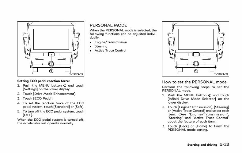
JVS0246X
Setting ECO pedal reaction force:
1. Push the MENU button and touch[Settings] on the lower display.
2. Touch [Drive Mode Enhancement].
3. Touch [ECO Pedal].
4. To set the reaction force of the ECOpedal system, touch [Standard] or [Soft].
5. To turn off the ECO pedal system, touch[OFF].
When the ECO pedal system is turned off,the accelerator will operate normally.
PERSONAL MODEWhen the PERSONAL mode is selected, thefollowing functions can be adjusted indivi-dually.
. Engine/Transmission
. Steering
. Active Trace Control
JVS0246X
How to set the PERSONAL modePerform the following steps to set thePERSONAL mode.
1. Push the MENU button and touch[Infiniti Drive Mode Selector] on thelower display.
2. Touch [Engine/Transmission], [Steering]or [Active Trace Control] and select eachitem. (See “Engine/Transmission”,“Steering” and “Active Trace Control”about the feature of each item.)
3. Touch [Back] or [Home] to finish thePERSONAL mode setting.
Starting and driving 5-23

5-24 Starting and driving
Engine/Transmission:
“Engine/Transmission” can be set to [Sport],[Eco], [Standard] or [Snow].
Steering:
Four combinations of steering effort andsteering response can be set.
Mode Response
Sport
Dynamic+
Dynamic
Default
Standard Default
Active Trace Control:
“Active Trace Control” can be set to ON(enabled) or OFF (disabled).
For details about the Active Trace Control,see “Active trace control” (P.5-132).
Reset Settings:
Touch [Reset Settings] and touch [OK] torestore all the PERSONAL mode settings todefault.
WARNING
Failure to follow the warnings andinstructions for proper use of ActiveLane Control could result in seriousinjury or death.
. Active Lane Control will not alwayssteer the vehicle to keep it in the lane.It is not designed to prevent loss ofcontrol. It is the driver’s responsibilityto stay alert, drive safely, keep thevehicle in the traveling lane, and be incontrol of vehicle at all times.
Active Lane Control enables the driver tomake fewer steering corrections on free-ways.
ACTIVE LANE CONTROL (if so equipped)
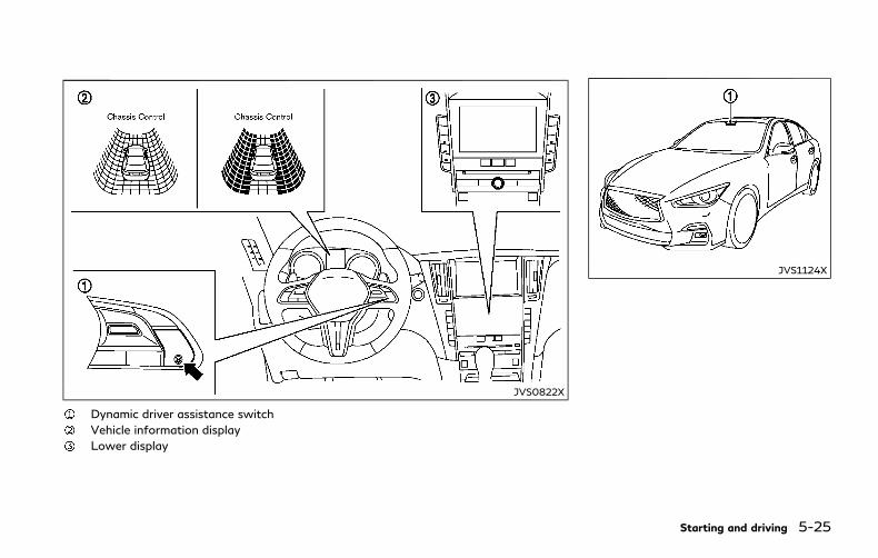
JVS0822X
Dynamic driver assistance switch
Vehicle information display
Lower display
JVS1124X
Starting and driving 5-25
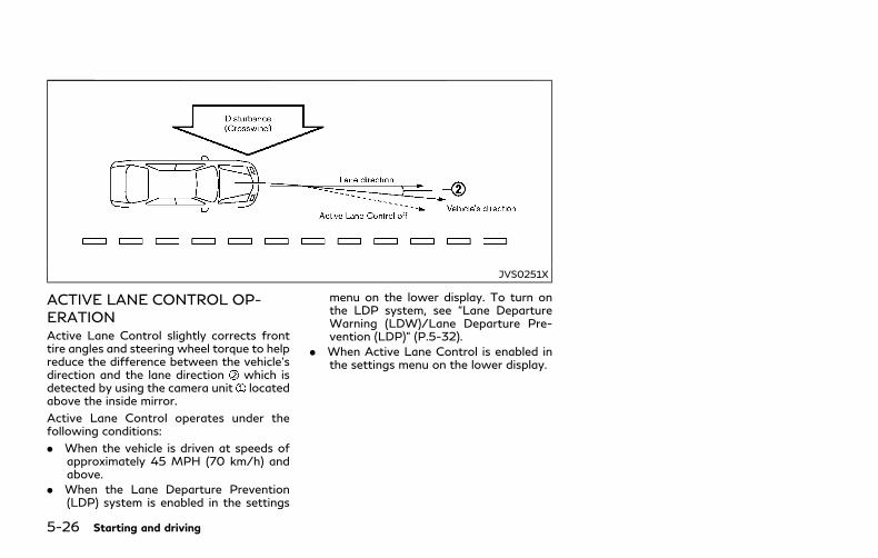
5-26 Starting and driving
JVS0251X
ACTIVE LANE CONTROL OP-ERATIONActive Lane Control slightly corrects fronttire angles and steering wheel torque to helpreduce the difference between the vehicle’sdirection and the lane direction which isdetected by using the camera unit locatedabove the inside mirror.
Active Lane Control operates under thefollowing conditions:
. When the vehicle is driven at speeds ofapproximately 45 MPH (70 km/h) andabove.
. When the Lane Departure Prevention(LDP) system is enabled in the settings
menu on the lower display. To turn onthe LDP system, see “Lane DepartureWarning (LDW)/Lane Departure Pre-vention (LDP)” (P.5-32).
. When Active Lane Control is enabled inthe settings menu on the lower display.
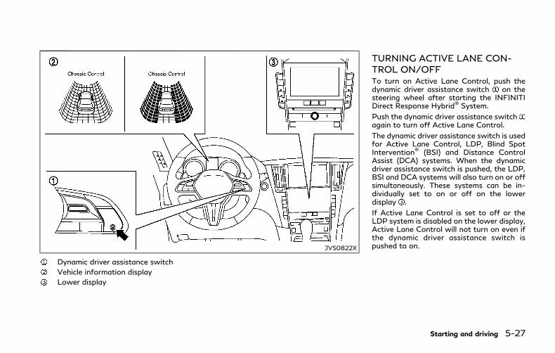
JVS0822X
Dynamic driver assistance switch
Vehicle information display
Lower display
TURNING ACTIVE LANE CON-TROL ON/OFFTo turn on Active Lane Control, push thedynamic driver assistance switch on thesteering wheel after starting the INFINITIDirect Response Hybrid® System.
Push the dynamic driver assistance switchagain to turn off Active Lane Control.
The dynamic driver assistance switch is usedfor Active Lane Control, LDP, Blind SpotIntervention® (BSI) and Distance ControlAssist (DCA) systems. When the dynamicdriver assistance switch is pushed, the LDP,BSI and DCA systems will also turn on or offsimultaneously. These systems can be in-dividually set to on or off on the lowerdisplay .
If Active Lane Control is set to off or theLDP system is disabled on the lower display,Active Lane Control will not turn on even ifthe dynamic driver assistance switch ispushed to on.
Starting and driving 5-27

5-28 Starting and driving
JVS0248X
The status of Active Lane Control can bechecked in the chassis control display in thevehicle information display .
. When Active Lane Control is turned on,the chassis control is displayed.
. When Active Lane Control is operationalor is operating, the chassis control isdisplayed.
For setting of the chassis control display, seeInfiniti InTouch Owner’s Manual.
JVS0246X
HOW TO ENABLE/DISABLE AC-TIVE LANE CONTROLPerform the following steps to enable ordisable Active Lane Control.
1. Push the MENU button and touch[Driver Assistance] on the lower display.
2. Touch [Lane Assist].
3. Touch [Active Lane Control] to enable ordisable Active Lane Control.
NOTE:
If the Lane Departure Prevention (LDP)system setting is OFF, Active Lane Controlcannot be operated. To use Active LaneControl, set the LDP system to ON. See
“How to enable/disable the LDP system”(P.5-36).
Active Lane Control settingsPerform the following steps to set ActiveLane Control.
1. Push the MENU button and touch[Driver Assistance] on the lower display.
2. Touch [Lane Assist].
3. Enable [Active Lane Control].
4. Touch [Active Lane Control setting] andselect [Low] or [High] to change thesetting of Active Lane Control.
ACTIVE LANE CONTROL LIM-ITATIONS
WARNING
Listed below are the limitations forActive Lane Control. Failure to operatethe vehicle in accordance with theselimitations could result in serious injuryor death.
. Active Lane Control is primarily in-tended for use on well-developedfreeways or highways. It may notdetect the lane markers for certainroads, weather or driving conditions.
. Using Active Lane Control undersome conditions of road, lane markeror weather, or if you attempt tochange lanes without using the lanechange signal could lead to an un-expected system operation. In suchconditions, you need to correct thevehicle’s direction with your steeringoperation to avoid accidents.
. Active Lane Control will not operateat speeds below approximately 45MPH (70 km/h) or if it cannot detectlane markers.
. Active Lane Control may not operateproperly and should not be usedunder the following conditions:
— During bad weather (rain, fog,snow, etc.).
— When driving on slippery roads,such as on ice or snow, etc.
— When driving on winding or un-even roads.
— When there is a lane closure dueto road repairs.
— When driving in a makeshift lane.
— When driving on roads where thelane width is too narrow.
— When driving with a tire that isnot within normal tire conditions
(for example, tire wear, low tirepressure, installation of tirechains, non-standard wheels).
— When the vehicle is equippedwithnon-original steering parts or sus-pension parts.
. Active Lane Control may or may notoperate properly under the followingconditions:
— On roads where there are multi-ple parallel lane markers; lanemarkers that are faded or notpainted clearly; yellow paintedlane markers; non-standard lanemarkers; or lane markers coveredwith water, dirt, snow, etc.
— On roads where discontinued lanemarkers are still detectable.
— On roads where there are sharpcurves.
— On roads where there are sharplycontrasting objects, such as sha-dows, snow, water, wheel ruts,seams or lines remaining afterroad repairs. (Active Lane Controlcould detect these items as lanemarkers.)
— On roads where the traveling lanemerges or separates.
Starting and driving 5-29
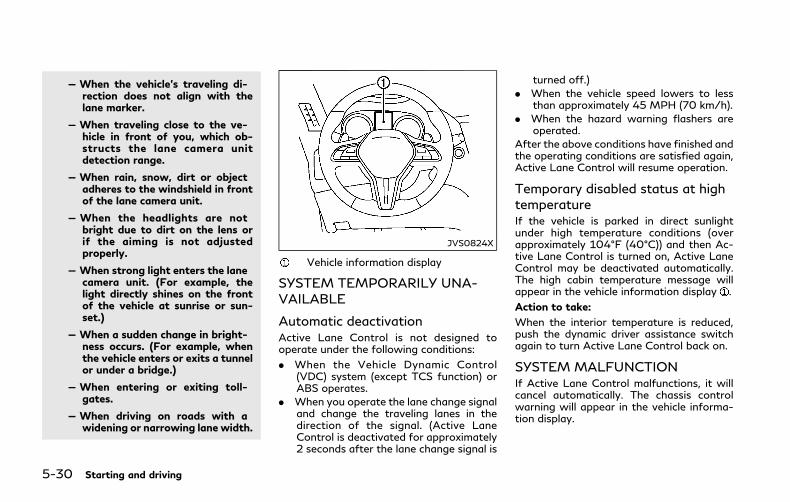
5-30 Starting and driving
— When the vehicle’s traveling di-rection does not align with thelane marker.
— When traveling close to the ve-hicle in front of you, which ob-structs the lane camera unitdetection range.
— When rain, snow, dirt or objectadheres to the windshield in frontof the lane camera unit.
— When the headlights are notbright due to dirt on the lens orif the aiming is not adjustedproperly.
— When strong light enters the lanecamera unit. (For example, thelight directly shines on the frontof the vehicle at sunrise or sun-set.)
— When a sudden change in bright-ness occurs. (For example, whenthe vehicle enters or exits a tunnelor under a bridge.)
— When entering or exiting toll-gates.
— When driving on roads with awidening or narrowing lane width.
JVS0824X
Vehicle information display
SYSTEM TEMPORARILY UNA-VAILABLE
Automatic deactivationActive Lane Control is not designed tooperate under the following conditions:
. When the Vehicle Dynamic Control(VDC) system (except TCS function) orABS operates.
. When you operate the lane change signaland change the traveling lanes in thedirection of the signal. (Active LaneControl is deactivated for approximately2 seconds after the lane change signal is
turned off.)
. When the vehicle speed lowers to lessthan approximately 45 MPH (70 km/h).
. When the hazard warning flashers areoperated.
After the above conditions have finished andthe operating conditions are satisfied again,Active Lane Control will resume operation.
Temporary disabled status at hightemperatureIf the vehicle is parked in direct sunlightunder high temperature conditions (overapproximately 104°F (40°C)) and then Ac-tive Lane Control is turned on, Active LaneControl may be deactivated automatically.The high cabin temperature message willappear in the vehicle information display .
Action to take:
When the interior temperature is reduced,push the dynamic driver assistance switchagain to turn Active Lane Control back on.
SYSTEM MALFUNCTIONIf Active Lane Control malfunctions, it willcancel automatically. The chassis controlwarning will appear in the vehicle informa-tion display.
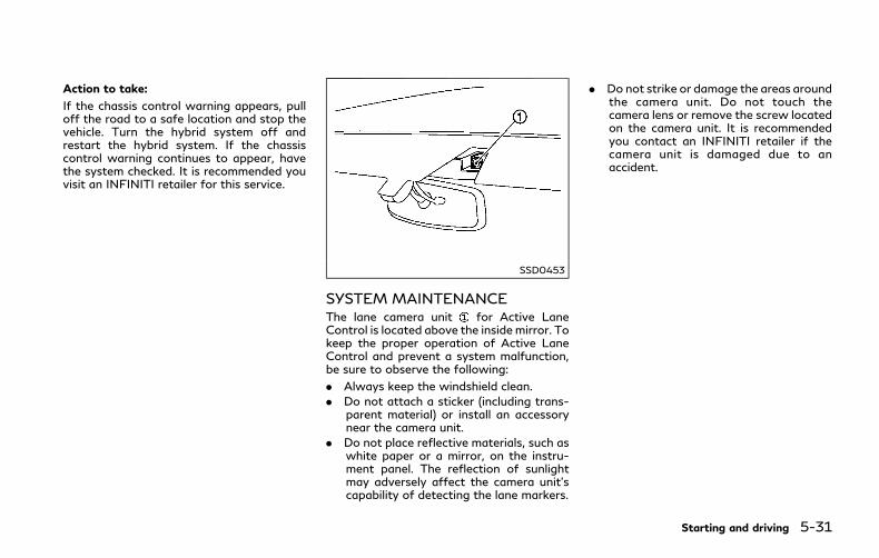
Action to take:
If the chassis control warning appears, pulloff the road to a safe location and stop thevehicle. Turn the hybrid system off andrestart the hybrid system. If the chassiscontrol warning continues to appear, havethe system checked. It is recommended youvisit an INFINITI retailer for this service.
SSD0453
SYSTEM MAINTENANCEThe lane camera unit for Active LaneControl is located above the inside mirror. Tokeep the proper operation of Active LaneControl and prevent a system malfunction,be sure to observe the following:
. Always keep the windshield clean.
. Do not attach a sticker (including trans-parent material) or install an accessorynear the camera unit.
. Do not place reflective materials, such aswhite paper or a mirror, on the instru-ment panel. The reflection of sunlightmay adversely affect the camera unit’scapability of detecting the lane markers.
. Do not strike or damage the areas aroundthe camera unit. Do not touch thecamera lens or remove the screw locatedon the camera unit. It is recommendedyou contact an INFINITI retailer if thecamera unit is damaged due to anaccident.
Starting and driving 5-31
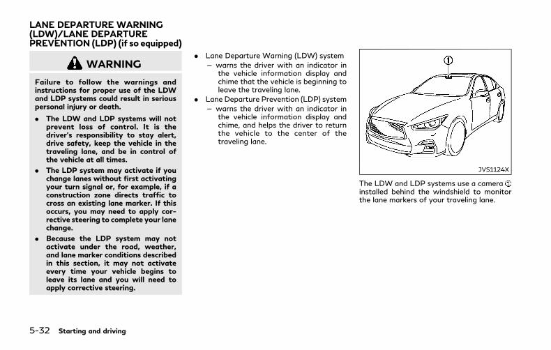
5-32 Starting and driving
WARNING
Failure to follow the warnings andinstructions for proper use of the LDWand LDP systems could result in seriouspersonal injury or death.
. The LDW and LDP systems will notprevent loss of control. It is thedriver’s responsibility to stay alert,drive safety, keep the vehicle in thetraveling lane, and be in control ofthe vehicle at all times.
. The LDP system may activate if youchange lanes without first activatingyour turn signal or, for example, if aconstruction zone directs traffic tocross an existing lane marker. If thisoccurs, you may need to apply cor-rective steering to complete your lanechange.
. Because the LDP system may notactivate under the road, weather,and lane marker conditions describedin this section, it may not activateevery time your vehicle begins toleave its lane and you will need toapply corrective steering.
. Lane Departure Warning (LDW) system
— warns the driver with an indicator inthe vehicle information display andchime that the vehicle is beginning toleave the traveling lane.
. Lane Departure Prevention (LDP) system
— warns the driver with an indicator inthe vehicle information display andchime, and helps the driver to returnthe vehicle to the center of thetraveling lane.
JVS1124X
The LDW and LDP systems use a camerainstalled behind the windshield to monitorthe lane markers of your traveling lane.
LANE DEPARTURE WARNING(LDW)/LANE DEPARTUREPREVENTION (LDP) (if so equipped)
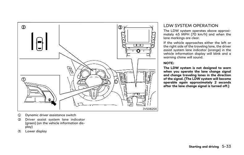
JVS0825X
Dynamic driver assistance switch
Driver assist system lane indicator(green) (on the vehicle information dis-play)
Lower display
LDW SYSTEM OPERATIONThe LDW system operates above approxi-mately 45 MPH (70 km/h) and when thelane markings are clear.
If the vehicle approaches either the left orthe right side of the traveling lane, the driverassist system lane indicator (orange) in thevehicle information display will blink and awarning chime will sound.
NOTE:
The LDW system is not designed to warnwhen you operate the lane change signaland change traveling lanes in the directionof the signal. (The LDW system will becomeoperable again approximately 2 secondsafter the lane change signal is turned off.)
Starting and driving 5-33

5-34 Starting and driving
JVS0246X
HOW TO ENABLE/DISABLE THELDW SYSTEMPerform the following steps to enable ordisable the LDW system.
1. Push the MENU button and touch[Driver Assistance] on the lower display.
2. Touch [Lane Assist].
3. Touch [Lane Departure Warning] toenable or disable the system.
LDP SYSTEM OPERATIONThe LDP system operates above approxi-mately 45 MPH (70 km/h) and when thelane markings are clear.
If the vehicle approaches either the left orright side of the traveling lane, the driverassist system lane indicator (orange) in thevehicle information display will blink and awarning chime will sound. Then, the LDPsystem will automatically assist the driver toreturn the vehicle to the center of thetraveling lane.
NOTE:. The LDP system is not designed to work
when you operate the lane change signaland change traveling lanes in the direc-tion of the signal. (The LDP system willbecome operable again approximately 2seconds after the lane change signal isturned off.)
. The LDP will not operate or will stopoperating and only a warning chime willsound under the following conditions.— When the steering wheel is turned as
far as necessary for the vehicle tochange lanes.
— When the accelerator pedal is de-pressed.
— When the Intelligent Cruise Control(ICC), Distance Control Assist (DCA),
Blind Spot Intervention® (BSI), BlindSpot Warning (BSW), Predictive For-ward Collision Warning (PFCW) orForward Emergency Braking (FEB)approach warning occurs.
— When the BSI system activates.— When the hazard warning flashers
are operated.— When driving on a curve at a high
speed.

JVS0825X
Dynamic driver assistance switch
Driver assist system lane indicator(green) (on the vehicle information dis-play)
Lower display
TURNING THE LDP SYSTEM ON/OFFTo turn on the LDP system, push thedynamic driver assistance switch on thesteering wheel after starting the INFINITIDirect Response Hybrid® System. The driverassist system lane indicator (green) in thevehicle information display will illuminate.
Push the dynamic driver assistance switchagain to turn off the LDP system. The driverassist system lane indicator will turn off.
The dynamic driver assistance switch isused for LDP, Active Lane Control, BlindSpot Intervention® (BSI) and Distance Con-trol Assist (DCA) systems. When the dy-namic driver assistance switch is pushed,Active Lane Control, BSI and DCA systemswill also turn on or off simultaneously. TheLDP system can be individually set to on oroff on the lower display .
If the system is set to off, the systemwill notturn on even if the dynamic driver assistanceswitch is pushed to on. To set the systemto on or off on the lower display, see “Howto enable/disable the LDP system” (P.5-36).
Starting and driving 5-35
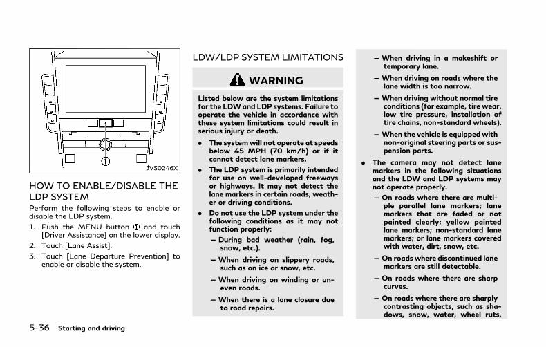
5-36 Starting and driving
JVS0246X
HOW TO ENABLE/DISABLE THELDP SYSTEMPerform the following steps to enable ordisable the LDP system.
1. Push the MENU button and touch[Driver Assistance] on the lower display.
2. Touch [Lane Assist].
3. Touch [Lane Departure Prevention] toenable or disable the system.
LDW/LDP SYSTEM LIMITATIONS
WARNING
Listed below are the system limitationsfor the LDWand LDP systems. Failure tooperate the vehicle in accordance withthese system limitations could result inserious injury or death.
. The systemwill not operate at speedsbelow 45 MPH (70 km/h) or if itcannot detect lane markers.
. The LDP system is primarily intendedfor use on well-developed freewaysor highways. It may not detect thelane markers in certain roads, weath-er or driving conditions.
. Do not use the LDP system under thefollowing conditions as it may notfunction properly:
— During bad weather (rain, fog,snow, etc.).
— When driving on slippery roads,such as on ice or snow, etc.
— When driving on winding or un-even roads.
— When there is a lane closure dueto road repairs.
— When driving in a makeshift ortemporary lane.
— When driving on roads where thelane width is too narrow.
— When driving without normal tireconditions (for example, tire wear,low tire pressure, installation oftire chains, non-standard wheels).
— When the vehicle is equippedwithnon-original steering parts or sus-pension parts.
. The camera may not detect lanemarkers in the following situationsand the LDW and LDP systems maynot operate properly.
— On roads where there are multi-ple parallel lane markers; lanemarkers that are faded or notpainted clearly; yellow paintedlane markers; non-standard lanemarkers; or lane markers coveredwith water, dirt, snow, etc.
— On roads where discontinued lanemarkers are still detectable.
— On roads where there are sharpcurves.
— On roads where there are sharplycontrasting objects, such as sha-dows, snow, water, wheel ruts,
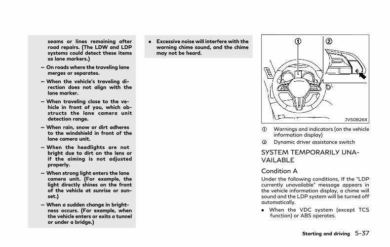
seams or lines remaining afterroad repairs. (The LDW and LDPsystems could detect these itemsas lane markers.)
— On roads where the traveling lanemerges or separates.
— When the vehicle’s traveling di-rection does not align with thelane marker.
— When traveling close to the ve-hicle in front of you, which ob-structs the lane camera unitdetection range.
— When rain, snow or dirt adheresto the windshield in front of thelane camera unit.
— When the headlights are notbright due to dirt on the lens orif the aiming is not adjustedproperly.
— When strong light enters the lanecamera unit. (For example, thelight directly shines on the frontof the vehicle at sunrise or sun-set.)
— When a sudden change in bright-ness occurs. (For example, whenthe vehicle enters or exits a tunnelor under a bridge.)
. Excessive noise will interfere with thewarning chime sound, and the chimemay not be heard.
JVS0826X
Warnings and indicators (on the vehicleinformation display)
Dynamic driver assistance switch
SYSTEM TEMPORARILY UNA-VAILABLE
Condition AUnder the following conditions, If the “LDPcurrently unavailable” message appears inthe vehicle information display, a chime willsound and the LDP system will be turned offautomatically.
. When the VDC system (except TCSfunction) or ABS operates.
Starting and driving 5-37

5-38 Starting and driving
. When the VDC system is turned off.
. When the INFINITI Drive Mode Selectoris turned to the SNOW mode.
Action to take:
When the above conditions no longer exist,push the dynamic driver assistance switchagain to turn the LDP system back on.
Condition BLDW system: If the vehicle is parked in directsunlight under high temperature conditions(over approximately 104°F (40°C)) and thenstarted, the LDW system may be deacti-vated automatically. The “high cabin tem-perature” warning message will appear inthe vehicle information display.
LDP system: If the vehicle is parked in directsunlight under high temperature conditions(over approximately 104°F (40°C)) and thenthe LDP system is turned on, the LDPsystem may be deactivated automatically.The “high cabin temperature” message willappear in the vehicle information display.
The LDW and LDP systems are not availableuntil the conditions no longer exist.
Action to take:
When the above conditions no longer exist,the LDW system will resume automatically.
For the LDP system, push the dynamic driverassistance switch again to turn the LDP
system back on.
SYSTEM MALFUNCTIONLDW system: If the LDW system malfunc-tions, it will cancel automatically, and theLDW “malfunction” message will appear inthe vehicle information display.
LDP system: If the LDP system malfunc-tions, it will cancel automatically. The LDP“malfunction” message will appear in thevehicle information display.
Action to take:
Stop the vehicle in a safe location, place thevehicle in the P (Park) position, turn thehybrid system off and restart the hybridsystem. If the “malfunction” message con-tinues to appear, have the system checked. Itis recommended you visit an INFINITI re-tailer for this service.
SSD0453
SYSTEM MAINTENANCEThe lane camera unit for LDW/LDPsystems is located above the inside mirror.To keep the proper operation of LDW/LDPsystems and prevent a system malfunction,be sure to observe the following:
. Always keep the windshield clean.
. Do not attach a sticker (including trans-parent material) or install an accessorynear the camera unit.
. Do not place reflective materials, such aswhite paper or a mirror, on the instru-ment panel. The reflection of sunlightmay adversely affect the camera unit’scapability of detecting the lane markers.
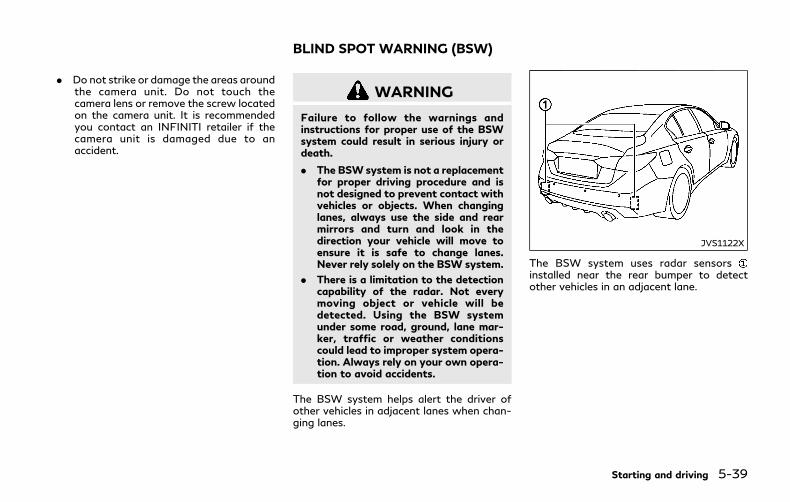
. Do not strike or damage the areas aroundthe camera unit. Do not touch thecamera lens or remove the screw locatedon the camera unit. It is recommendedyou contact an INFINITI retailer if thecamera unit is damaged due to anaccident.
WARNING
Failure to follow the warnings andinstructions for proper use of the BSWsystem could result in serious injury ordeath.
. The BSW system is not a replacementfor proper driving procedure and isnot designed to prevent contact withvehicles or objects. When changinglanes, always use the side and rearmirrors and turn and look in thedirection your vehicle will move toensure it is safe to change lanes.Never rely solely on the BSW system.
. There is a limitation to the detectioncapability of the radar. Not everymoving object or vehicle will bedetected. Using the BSW systemunder some road, ground, lane mar-ker, traffic or weather conditionscould lead to improper system opera-tion. Always rely on your own opera-tion to avoid accidents.
The BSW system helps alert the driver ofother vehicles in adjacent lanes when chan-ging lanes.
JVS1122X
The BSW system uses radar sensorsinstalled near the rear bumper to detectother vehicles in an adjacent lane.
Starting and driving 5-39
BLIND SPOT WARNING (BSW)

5-40 Starting and driving
SSD1030
Detection zoneThe radar sensors can detect vehicles oneither side of your vehicle within the detec-tion zone shown as illustrated. This detec-tion zone starts from the outside mirror ofyour vehicle and extends approximately 10ft (3.0 m) behind the rear bumper, andapproximately 10 ft (3.0 m) sideways.
JVS0827X
Side indicator light
Driver assist system blind spot indica-tor (on the vehicle information display)
Lower display
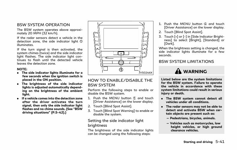
BSW SYSTEM OPERATIONThe BSW system operates above approxi-mately 20 MPH (32 km/h).
If the radar sensors detect a vehicle in thedetection zone, the side indicator lightilluminates.
If the turn signal is then activated, thesystem chimes (twice) and the side indicatorlight flashes. The side indicator light con-tinues to flash until the detected vehicleleaves the detection zone.
NOTE:. The side indicator lights illuminate for a
few seconds when the ignition switch isplaced in the ON position.
. The brightness of the side indicatorlights is adjusted automatically depend-ing on the brightness of the ambientlight.
. If a vehicle comes into the detection zoneafter the driver activates the turnsignal, then only the side indicator lightflashes and no chime sounds. (See “BSWdriving situations” (P.5-42).)
JVS0246X
HOW TO ENABLE/DISABLE THEBSW SYSTEMPerform the following steps to enable ordisable the BSW system.
1. Push the MENU button and touch[Driver Assistance] on the lower display.
2. Touch [Blind Spot Assist].
3. Touch [Blind Spot Warning] to enable ordisable the system.
Setting the side indicator lightbrightnessThe brightness of the side indicator lightscan be changed using the following steps:
1. Push the MENU button and touch[Driver Assistance] on the lower display.
2. Touch [Blind Spot Assist].
3. Touch [+] or [-] in [Side Indicator Bright-ness] to select [Bright], [Standard] or[Dark].
When the brightness setting is changed, theside indicator lights illuminate for a fewseconds.
BSW SYSTEM LIMITATIONS
WARNING
Listed below are the system limitationsfor the BSW system. Failure to operatethe vehicle in accordance with thesesystem limitations could result in seriousinjury or death.
. The BSW system cannot detect allvehicles under all conditions.
. The radar sensors may not be able todetect and activate BSW when cer-tain objects are present such as:
— Pedestrians, bicycles, animals.
— Vehicles such as motorcycles, lowheight vehicles, or high groundclearance vehicles.
Starting and driving 5-41
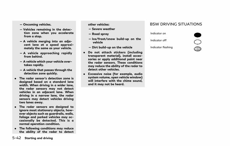
5-42 Starting and driving
— Oncoming vehicles.
— Vehicles remaining in the detec-tion zone when you acceleratefrom a stop.
— A vehicle merging into an adja-cent lane at a speed approxi-mately the same as your vehicle.
— A vehicle approaching rapidlyfrom behind.
— A vehicle which your vehicle over-takes rapidly.
— A vehicle that passes through thedetection zone quickly.
. The radar sensor’s detection zone isdesigned based on a standard lanewidth. When driving in a wider lane,the radar sensors may not detectvehicles in an adjacent lane. Whendriving in a narrow lane, the radarsensors may detect vehicles drivingtwo lanes away.
. The radar sensors are designed toignore most stationary objects, how-ever objects such as guardrails, walls,foliage and parked vehicles may oc-casionally be detected. This is anormal operation condition.
. The following conditions may reducethe ability of the radar to detect
other vehicles:
— Severe weather
— Road spray
— Ice/frost/snow build-up on thevehicle
— Dirt build-up on the vehicle
. Do not attach stickers (includingtransparent material), install acces-sories or apply additional paint nearthe radar sensors. These conditionsmay reduce the ability of the radar todetect other vehicles.
. Excessive noise (for example, audiosystem volume, open vehicle window)will interfere with the chime sound,and it may not be heard.
BSW DRIVING SITUATIONS
Indicator on
Indicator off
Indicator flashing
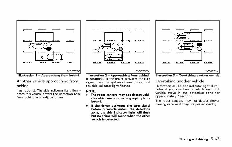
JVS0737X
Illustration 1 – Approaching from behind
Another vehicle approaching frombehindIllustration 1: The side indicator light illumi-nates if a vehicle enters the detection zonefrom behind in an adjacent lane.
JVS0738X
Illustration 2 – Approaching from behindIllustration 2: If the driver activates the turnsignal, then the system chimes (twice) andthe side indicator light flashes.
NOTE:. The radar sensors may not detect vehi-
cles which are approaching rapidly frombehind.
. If the driver activates the turn signalbefore a vehicle enters the detectionzone, the side indicator light will flashbut no chime will sound when the othervehicle is detected.
JVS0739X
Illustration 3 – Overtaking another vehicle
Overtaking another vehicleIllustration 3: The side indicator light illumi-nates if you overtake a vehicle and thatvehicle stays in the detection zone forapproximately 3 seconds.
The radar sensors may not detect slowermoving vehicles if they are passed quickly.
Starting and driving 5-43

5-44 Starting and driving
JVS0740X
Illustration 4 – Overtaking another vehicleIllustration 4: If the driver activates the turnsignal while another vehicle is in the detec-tion zone, then the system chimes (twice)and the side indicator light flashes.
NOTE:. When overtaking several vehicles in a
row, the vehicles after the first vehiclemay not be detected if they are travel-ing close together.
. The radar sensors may not detect slowermoving vehicles if they are passedquickly.
. If the driver activates the turn signalbefore a vehicle enters the detectionzone, the side indicator light will flashbut no chime will sound when the other
vehicle is detected.
JVS0741X
Illustration 5 – Entering from the side
Entering from the sideIllustration 5: The side indicator light illumi-nates if a vehicle enters the detection zonefrom either side.

JVS0742X
Illustration 6 – Entering from the sideIllustration 6: If the driver activates the turnsignal, then the system chimes (twice) andthe side indicator light flashes.
NOTE:. The radar sensors may not detect a
vehicle which is traveling at about thesame speed as your vehicle when itenters the detection zone.
. If the driver activates the turn signalbefore a vehicle enters the detectionzone, the side indicator light will flashbut no chime will sound when the othervehicle is detected.
JVS0824X
Vehicle information display
SYSTEM TEMPORARILY UNA-VAILABLEWhen radar blockage is detected, the BSWsystem will be turned off automatically, achime will sound and the “side radar ob-struction” warning message will appear inthe vehicle information display .
The system is not available until the condi-tions no longer exist.
The radar sensors may be blocked bytemporary ambient conditions such assplashing water, mist or fog. The blockedcondition may also be caused by objectssuch as ice, frost or dirt obstructing the radar
sensors.
Action to take:
When the above conditions no longer exist,the system will resume automatically.
If the “side radar obstruction” warningmessage continues to appear, have thesystem checked. It is recommended you visitan INFINITI retailer for this service.
SYSTEM MALFUNCTIONWhen the BSW system malfunctions, it willbe turned off automatically, a chime willsound, and the system “malfunction” warn-ing message with the driver assist systemblind spot indicator (orange) will appear inthe vehicle information display.
Action to take:
Stop the vehicle in a safe location and placethe shift lever in the P (Park) position. Turnthe INFINITI Direct Response Hybrid® Sys-tem off and restart the hybrid system. If thesystem “malfunction” warning message withthe driver assist system blind spot indicator(orange) continues to be displayed, have theBSW system checked. It is recommendedyou visit an INFINITI retailer for this service.
Starting and driving 5-45
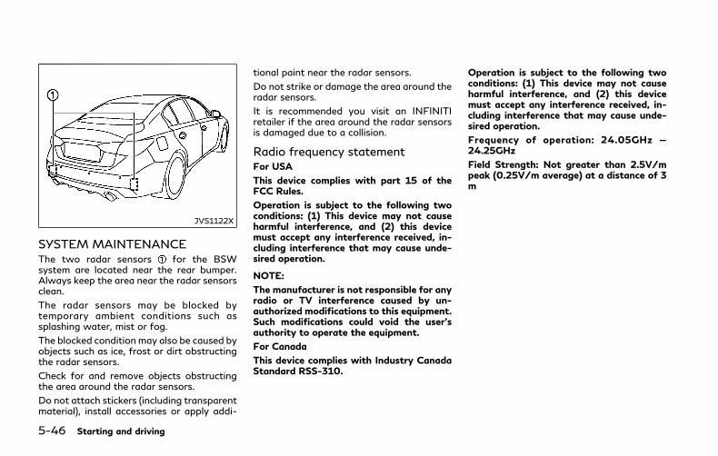
5-46 Starting and driving
JVS1122X
SYSTEM MAINTENANCEThe two radar sensors for the BSWsystem are located near the rear bumper.Always keep the area near the radar sensorsclean.
The radar sensors may be blocked bytemporary ambient conditions such assplashing water, mist or fog.
The blocked condition may also be caused byobjects such as ice, frost or dirt obstructingthe radar sensors.
Check for and remove objects obstructingthe area around the radar sensors.
Do not attach stickers (including transparentmaterial), install accessories or apply addi-
tional paint near the radar sensors.
Do not strike or damage the area around theradar sensors.
It is recommended you visit an INFINITIretailer if the area around the radar sensorsis damaged due to a collision.
Radio frequency statementFor USA
This device complies with part 15 of theFCC Rules.
Operation is subject to the following twoconditions: (1) This device may not causeharmful interference, and (2) this devicemust accept any interference received, in-cluding interference that may cause unde-sired operation.
NOTE:
The manufacturer is not responsible for anyradio or TV interference caused by un-authorized modifications to this equipment.Such modifications could void the user’sauthority to operate the equipment.
For Canada
This device complies with Industry CanadaStandard RSS-310.
Operation is subject to the following twoconditions: (1) This device may not causeharmful interference, and (2) this devicemust accept any interference received, in-cluding interference that may cause unde-sired operation.
Frequency of operation: 24.05GHz —24.25GHz
Field Strength: Not greater than 2.5V/mpeak (0.25V/m average) at a distance of 3m
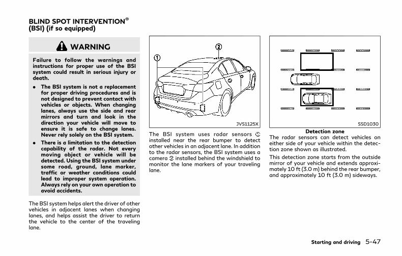
WARNING
Failure to follow the warnings andinstructions for proper use of the BSIsystem could result in serious injury ordeath.
. The BSI system is not a replacementfor proper driving procedures and isnot designed to prevent contact withvehicles or objects. When changinglanes, always use the side and rearmirrors and turn and look in thedirection your vehicle will move toensure it is safe to change lanes.Never rely solely on the BSI system.
. There is a limitation to the detectioncapability of the radar. Not everymoving object or vehicle will bedetected. Using the BSI system undersome road, ground, lane marker,traffic or weather conditions couldlead to improper system operation.Always rely on your own operation toavoid accidents.
The BSI system helps alert the driver of othervehicles in adjacent lanes when changinglanes, and helps assist the driver to returnthe vehicle to the center of the travelinglane.
JVS1125X
The BSI system uses radar sensorsinstalled near the rear bumper to detectother vehicles in an adjacent lane. In additionto the radar sensors, the BSI system uses acamera installed behind the windshield tomonitor the lane markers of your travelinglane.
SSD1030
Detection zoneThe radar sensors can detect vehicles oneither side of your vehicle within the detec-tion zone shown as illustrated.
This detection zone starts from the outsidemirror of your vehicle and extends approxi-mately 10 ft (3.0 m) behind the rear bumper,and approximately 10 ft (3.0 m) sideways.
Starting and driving 5-47
BLIND SPOT INTERVENTION®
(BSI) (if so equipped)
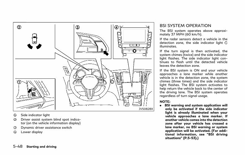
5-48 Starting and driving
JVS0828X
Side indicator light
Driver assist system blind spot indica-tor (on the vehicle information display)
Dynamic driver assistance switch
Lower display
BSI SYSTEM OPERATIONThe BSI system operates above approxi-mately 37 MPH (60 km/h).
If the radar sensors detect a vehicle in thedetection zone, the side indicator lightilluminates.
If the turn signal is then activated, thesystem chimes (twice) and the side indicatorlight flashes. The side indicator light con-tinues to flash until the detected vehicleleaves the detection zone.
If the BSI system is ON and your vehicleapproaches a lane marker while anothervehicle is in the detection zone, the systemchimes (three times) and the side indicatorlight flashes. The BSI system activates tohelp return the vehicle back to the center ofthe driving lane. The BSI system operatesregardless of turn signal usage.
NOTE:. BSI warning and system application will
only be activated if the side indicatorlight is already illuminated when yourvehicle approaches a lane marker. Ifanother vehicle comes into the detectionzone after your vehicle has crossed alane marker, no BSI warning or systemapplication will be activated. (For addi-tional information, see “BSI drivingsituations” (P.5-53).)
. The BSI system is typically activatedearlier than the Lane Departure Preven-tion (LDP) system when your vehicle isapproaching a lane marker.
Starting and driving 5-49

5-50 Starting and driving
JVS0829X
Driver assist system blind spot indica-tor (green) (on the vehicle informationdisplay)
Dynamic driver assistance switch
Lower display
TURNING THE BSI SYSTEM ON/OFFTo turn on the BSI system, push the dynamicdriver assistance switch on the steeringwheel after starting the INFINITI DirectResponse Hybrid® System. The driver assistsystem blind spot indicator (green) in thevehicle information display will illuminate.
Push the dynamic driver assistance switchagain to turn off the BSI system. The driverassist system blind spot indicator will turnoff.
The dynamic driver assistance switch isused for the BSI, Active Lane Control, LaneDeparture Prevention (LDP) and DistanceControl Assist (DCA) systems. When thedynamic driver assistance switch ispushed, Active Lane Control, LDP and DCAsystems will also turn on or off simulta-neously. The BSI system can be individuallyset to on or off on the lower display .
If the system is set to off, the systemwill notturn on even if the dynamic driver assistanceswitch is pushed to on. To set the systemto on or off on the lower display, see “Howto enable/disable the BSI system” (P.5-51).

JVS0246X
HOW TO ENABLE/DISABLE THEBSI SYSTEMPerform the following steps to enable ordisable the BSI system.
1. Push the MENU button and touch[Driver Assistance] on the lower display.
2. Touch [Blind Spot Assist].
3. Touch [Blind Spot Intervention] to en-able or disable the system.
Setting the side indicator lightbrightnessThe brightness of the side indicator lightscan be changed using the following steps:
1. Push the MENU button and touch[Driver Assistance] on the lower display.
2. Touch [Blind Spot Assist].
3. Touch [+] or [-] in [Side Indicator Bright-ness] to select [Bright], [Standard] or[Dark].
When the brightness setting is changed, theside indicator lights illuminate for a fewseconds.
BSI SYSTEM LIMITATIONS
WARNING
Listed below are the system limitationsfor the BSI system. Failure to operatethe vehicle in accordance with thesesystem limitations could result in seriousinjury or death.
. The BSI system cannot detect allvehicles under all conditions.
. The radar sensors may not be able todetect and activate BSI when certainobjects are present such as:
— Pedestrians, bicycles, animals.
— Vehicles such as motorcycles, lowheight vehicles, or high groundclearance vehicles.
— Vehicles remaining in the detec-tion zone when you acceleratefrom a stop.
— Oncoming vehicles.
— A vehicle merging into an adja-cent lane at a speed approxi-mately the same as your vehicle.
— A vehicle approaching rapidlyfrom behind.
— A vehicle which your vehicle over-takes rapidly.
— A vehicle that passes through thedetection zone quickly.
. The radar sensor’s detection zone isdesigned based on a standard lanewidth. When driving in a wider lane,the radar sensors may not detectvehicles in an adjacent lane. Whendriving in a narrow lane, the radarsensors may detect vehicles drivingtwo lanes away.
. The radar sensors are designed toignore most stationary objects, how-ever objects such as guardrails, walls,foliage and parked vehicles may oc-casionally be detected. This is anormal operation condition.
. The camera may not detect lanemarkers in the following situations
Starting and driving 5-51
5-52 Starting and driving
and the BSI system may not operateproperly.
— On roads where there are multi-ple parallel lane markers; lanemarkers that are faded or notpainted clearly; yellow paintedlane markers; nonstandard lanemarkers; lane markers coveredwith water, dirt, snow, etc.
— On roads where discontinued lanemarkers are still detectable.
— On roads where there are sharpcurves.
— On roads where there are sharplycontrasting objects, such as sha-dows, snow, water, wheel ruts,seams or lines remaining afterroad repairs.
— On roads where the traveling lanemerges or separates.
— When the vehicle’s traveling di-rection does not align with thelane markers.
— When traveling close to the ve-hicle in front of you, which ob-structs the lane camera unitdetection range.
— When rain, snow or dirt adheresto the windshield in front of a lane
camera unit.
— When the headlights are notbright due to dirt on the lens orif aiming is not adjusted properly.
— When strong light enters a lanecamera unit. (For example: lightdirectly shines on the front of thevehicle at sunrise or sunset.)
— When a sudden change in bright-ness occurs. (For example: whenthe vehicle enters or exits a tunnelor under a bridge.)
. Do not use the BSI system under thefollowing conditions because the sys-tem may not function properly.
— During bad weather. (For exam-ple: rain, fog, snow, etc.)
— When driving on slippery roads,such as on ice or snow, etc.
— When driving on winding or un-even roads.
— When there is a lane closure dueto road repairs.
— When driving in a makeshift ortemporary lane.
— When driving on roads where thelane width is too narrow.
— When driving with a tire that isnot within normal tire conditions(for example, tire wear, low tirepressure, installation of tirechains, non-standard wheels).
— When the vehicle is equippedwithnon-original steering parts or sus-pension parts.
. Excessive noise (for example, audiosystem volume, open vehicle window)will interfere with the chime sound,and it may not be heard.

BSI DRIVING SITUATIONS
Indicator on
Indicator off
Indicator flashing
JVS0737X
Illustration 1 - Approaching from behind
Another vehicle approaching frombehindIllustration 1: The side indicator light illumi-nates if a vehicle enters the detection zonefrom behind in an adjacent lane.
JVS0738X
Illustration 2 - Approaching from behindIllustration 2: If the driver activates the turnsignal then the system chimes a sound(twice) and the side indicator light flashes.
Starting and driving 5-53
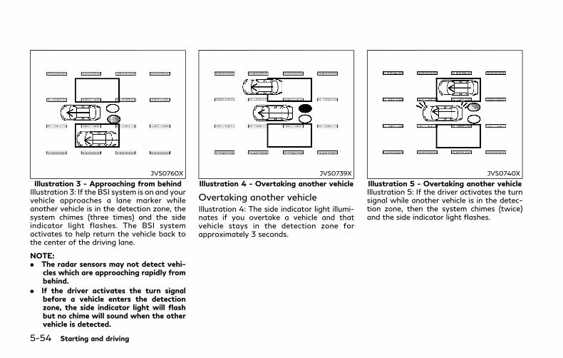
5-54 Starting and driving
JVS0760X
Illustration 3 - Approaching from behindIllustration 3: If the BSI system is on and yourvehicle approaches a lane marker whileanother vehicle is in the detection zone, thesystem chimes (three times) and the sideindicator light flashes. The BSI systemactivates to help return the vehicle back tothe center of the driving lane.
NOTE:. The radar sensors may not detect vehi-
cles which are approaching rapidly frombehind.
. If the driver activates the turn signalbefore a vehicle enters the detectionzone, the side indicator light will flashbut no chime will sound when the othervehicle is detected.
JVS0739X
Illustration 4 - Overtaking another vehicle
Overtaking another vehicleIllustration 4: The side indicator light illumi-nates if you overtake a vehicle and thatvehicle stays in the detection zone forapproximately 3 seconds.
JVS0740X
Illustration 5 - Overtaking another vehicleIllustration 5: If the driver activates the turnsignal while another vehicle is in the detec-tion zone, then the system chimes (twice)and the side indicator light flashes.

JVS0761X
Illustration 6 - Overtaking another vehicleIllustration 6: If the BSI system is on and yourvehicle approaches a lane marker whileanother vehicle is in the detection zone, thesystem chimes (three times) and the sideindicator light flashes. The BSI systemactivates to help return the vehicle back tothe center of the driving lane.
NOTE:. When overtaking several vehicles in a
row, the vehicles after the first vehiclemay not be detected if they are travel-ing close together.
. The radar sensors may not detect slowermoving vehicles if they are passedquickly.
. If the driver activates the turn signalbefore a vehicle enters the detectionzone, the side indicator light will flashbut no chime will sound when the othervehicle is detected.
JVS0741X
Illustration 7 - Entering from the side
Entering from the sideIllustration 7: The side indicator light illumi-nates if a vehicle enters the detection zonefrom either side.
NOTE:
The radar sensors may not detect a vehiclewhich is traveling at about the same speedas your vehicle when it enters the detectionzone.
Starting and driving 5-55

5-56 Starting and driving
JVS0742X
Illustration 8 - Entering from the sideIllustration 8: If the driver activates the turnsignal while another vehicle is in the detec-tion zone, then the side indicator lightflashes and a chime will sound twice.
NOTE:
If the driver activates the turn signal beforea vehicle enters the detection zone, the sideindicator light will flash but no chime willsound when another vehicle is detected.
JVS0761X
Illustration 9 - Entering from the sideIllustration 9: If the BSI system is on and yourvehicle approaches the lane marker whileanother vehicle is in the detection zone, thesystem chimes (three times) and the sideindicator light flashes. The BSI systemactivates to help return the vehicle back tothe center of the driving lane.
JVS0742X
Illustration 10 - Entering from the sideIllustration 10: The BSI system will notoperate if your vehicle is on a lane markerwhen another vehicle enters the detectionzone. In this case only the BSW systemoperates.
NOTE:. The radar sensors may not detect a
vehicle which is traveling at about thesame speed as your vehicle when itenters the detection zone.
. If the driver activates the turn signalbefore a vehicle enters the detectionzone, the side indicator light will flashbut no chime will sound when the othervehicle is detected.
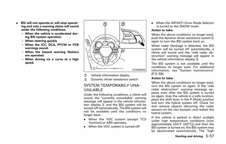
. BSI will not operate or will stop operat-ing and only a warning chime will soundunder the following conditions.— When the vehicle is accelerated dur-
ing BSI system operation— When steering quickly— When the ICC, DCA, PFCW or FEB
warnings sound.— When the hazard warning flashers
are operated.— When driving on a curve at a high
speed.
JVS0826X
Vehicle information display
Dynamic driver assistance switch
SYSTEM TEMPORARILY UNA-VAILABLEUnder the following conditions, a chime willsound, the “currently unavailable” warningmessage will appear in the vehicle informa-tion display and the BSI system will beturned off automatically. The BSI systemwillnot be available until the conditions nolonger exist.
. When the VDC system (except TCSfunction) or ABS operates.
. When the VDC system is turned off.
. When the INFINITI Drive Mode Selectoris turned to the SNOW mode.
Action to take:
When the above conditions no longer exist,push the dynamic driver assistance switchagain to turn the BSI system back on.
When radar blockage is detected, the BSIsystem will be turned off automatically, achime will sound and the “side radar ob-struction” warning message will appear inthe vehicle information display .
The BSI system is not available until theconditions no longer exist. For additionalinformation, see “System maintenance”(P.5-58).
Action to take:
When the above conditions no longer exist,turn the BSI system on again. If the “sideradar obstruction” warning message ap-pears even after the BSI system is turnedon again, stop the vehicle in a safe location,place the shift lever in the P (Park) positionand turn the hybrid system off. Check forand remove objects obscuring the radarsensors on the rear bumper, and restart thehybrid system.
If the vehicle is parked in direct sunlightunder high temperature conditions (overapproximately 104°F (40°C)) and then theBSI system is turned on, the BSI system maybe deactivated automatically. The “high
Starting and driving 5-57
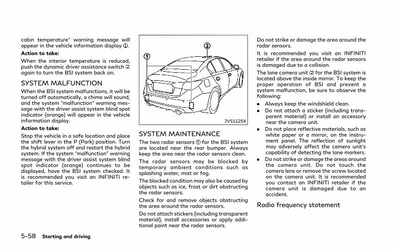
5-58 Starting and driving
cabin temperature” warning message willappear in the vehicle information display .
Action to take:
When the interior temperature is reduced,push the dynamic driver assistance switchagain to turn the BSI system back on.
SYSTEM MALFUNCTIONWhen the BSI system malfunctions, it will beturned off automatically, a chime will sound,and the system “malfunction” warning mes-sage with the driver assist system blind spotindicator (orange) will appear in the vehicleinformation display.
Action to take:
Stop the vehicle in a safe location and placethe shift lever in the P (Park) position. Turnthe hybrid system off and restart the hybridsystem. If the system “malfunction” warningmessage with the driver assist system blindspot indicator (orange) continues to bedisplayed, have the BSI system checked. Itis recommended you visit an INFINITI re-tailer for this service.
JVS1125X
SYSTEM MAINTENANCEThe two radar sensors for the BSI systemare located near the rear bumper. Alwayskeep the area near the radar sensors clean.
The radar sensors may be blocked bytemporary ambient conditions such assplashing water, mist or fog.
The blocked condition may also be caused byobjects such as ice, frost or dirt obstructingthe radar sensors.
Check for and remove objects obstructingthe area around the radar sensors.
Do not attach stickers (including transparentmaterial), install accessories or apply addi-tional paint near the radar sensors.
Do not strike or damage the area around theradar sensors.
It is recommended you visit an INFINITIretailer if the area around the radar sensorsis damaged due to a collision.
The lane camera unit for the BSI system islocated above the inside mirror. To keep theproper operation of BSI and prevent asystem malfunction, be sure to observe thefollowing:
. Always keep the windshield clean.
. Do not attach a sticker (including trans-parent material) or install an accessorynear the camera unit.
. Do not place reflective materials, such aswhite paper or a mirror, on the instru-ment panel. The reflection of sunlightmay adversely affect the camera unit’scapability of detecting the lane markers.
. Do not strike or damage the areas aroundthe camera unit. Do not touch thecamera lens or remove the screw locatedon the camera unit. It is recommendedyou contact an INFINITI retailer if thecamera unit is damaged due to anaccident.
Radio frequency statement
For USA
This device complies with part 15 of theFCC Rules.
Operation is subject to the following twoconditions: (1) This device may not causeharmful interference, and (2) this devicemust accept any interference received, in-cluding interference that may cause unde-sired operation.
NOTE:
The manufacturer is not responsible for anyradio or TV interference caused by un-authorized modifications to this equipment.Such modifications could void the user’sauthority to operate the equipment.
For Canada
This device complies with Industry CanadaStandard RSS-310.
Operation is subject to the following twoconditions: (1) This device may not causeharmful interference, and (2) this devicemust accept any interference received, in-cluding interference that may cause unde-sired operation.
Frequency of operation: 24.05GHz —24.25GHz
Field Strength: Not greater than 2.5V/mpeak (0.25V/m average) at a distance of 3m
WARNING
Failure to follow the warnings andinstructions for proper use of the BCIsystem could result in serious injury ordeath.
. The BCI system is not a replacementfor proper driving procedure, is notdesigned to prevent contact withvehicles or objects and does notprovide full brake power.When back-ing out of parking spaces, always usethe inside and rear mirrors and turnand look in the direction you willmove. Never rely solely on the BCIsystem.
. There is a limitation to the detectioncapability of the radar or the sonar.Using the BCI system under someroad, ground, traffic or weather con-ditions could lead to improper systemoperation. Always rely on your ownoperation to avoid accidents.
The BCI system can help alert the driver ofan approaching vehicle or objects behind thevehicle when the driver is backing out of aparking space.
Starting and driving 5-59
BACK-UP COLLISIONINTERVENTION (BCI)

5-60 Starting and driving
JVS1121X
The BCI system uses radar sensorsinstalled on both sides near the rear bumperto detect an approaching vehicle and sonarsensors to detect objects in the rear.
JVS0173X
JVS0234X
The radar sensors detect an approaching
vehicle from up to approximately 49 ft (15m) away. The sonar sensors detectstationary objects behind the vehicle up toapproximately 4.9 ft (1.5 m). Refer to theillustration for approximate zone coverageareas .

JVS0831X
Side indicator light
BCI ON indicator
Upper display
Lower display
JVS0173X
BCI SYSTEM OPERATIONWhen the shift lever is in the R (Reverse)position and the vehicle speed is less thanapproximately 5 MPH (8 km/h), the BCIsystem operates.
If the radar detects a vehicle approachingfrom the side or the sonar detects closestationary objects behind the vehicle, thesystem gives visual and audible warnings. Ifthe driver does not apply the brakes, thesystem automatically applies the brake for amoment when the vehicle is moving back-wards. After the automatic brake applica-tion, the driver must depress the brake pedalto maintain brake pressure. If the driver’sfoot is on the accelerator pedal, the system
Starting and driving 5-61
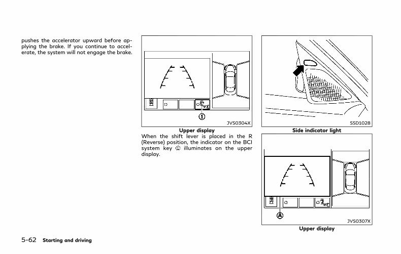
5-62 Starting and driving
pushes the accelerator upward before ap-plying the brake. If you continue to accel-erate, the system will not engage the brake.
JVS0304X
Upper displayWhen the shift lever is placed in the R(Reverse) position, the indicator on the BCIsystem key illuminates on the upperdisplay.
SSD1028
Side indicator light
JVS0307X
Upper display

If the radar detects an approaching vehiclefrom the side, the system chimes (once), theside indicator light on the side the vehicle isapproaching from flashes and a yellowrectangular frame appears on the upperdisplay.
JVS0172X
Illustration 1
JVS0173X
Illustration 2
NOTE:. In the case of several vehicles approach-
ing in a row (Illustration 1) or in theopposite direction (Illustration 2), achime may not be sounded by the BCIsystem after the first vehicle passes thesensors.
. The sonar system chime indicating thereis an object behind the vehicle has ahigher priority than the BCI chime(single beep) indicating an approachingvehicle. If the sonar system detects anobject behind the vehicle and the BCIsystem detects an approaching vehicleat the same time, the following indica-tions are provided:— The sonar system chime sounds— The side indicator light on the side of
the approaching vehicle flashes, and— A yellow rectangular frame appears
in the display.
Starting and driving 5-63

5-64 Starting and driving
JVS0307X
If an approaching vehicle or object behindthe vehicle is detected when your vehicle isbacking up, a red frame will appear on theupper display and the system will chimethree times. Then, the brakes will be appliedmomentarily. After the automatic brakeapplication, the driver must depress thebrake pedal to maintain brake pressure.
If the driver’s foot is on the acceleratorpedal, the system moves the acceleratorpedal upward before the braking is applied.However, if you continue to accelerate, thesystem will not engage the brakes.
The BCI system does not operate if theobject is very close to the bumper.
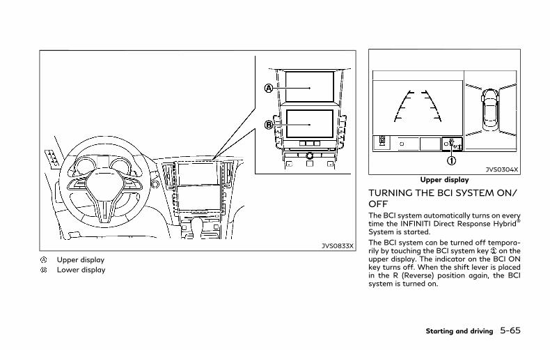
JVS0833X
Upper display
Lower display
JVS0304X
Upper display
TURNING THE BCI SYSTEM ON/OFFThe BCI system automatically turns on everytime the INFINITI Direct Response Hybrid®
System is started.
The BCI system can be turned off tempora-rily by touching the BCI system key on theupper display. The indicator on the BCI ONkey turns off. When the shift lever is placedin the R (Reverse) position again, the BCIsystem is turned on.
Starting and driving 5-65
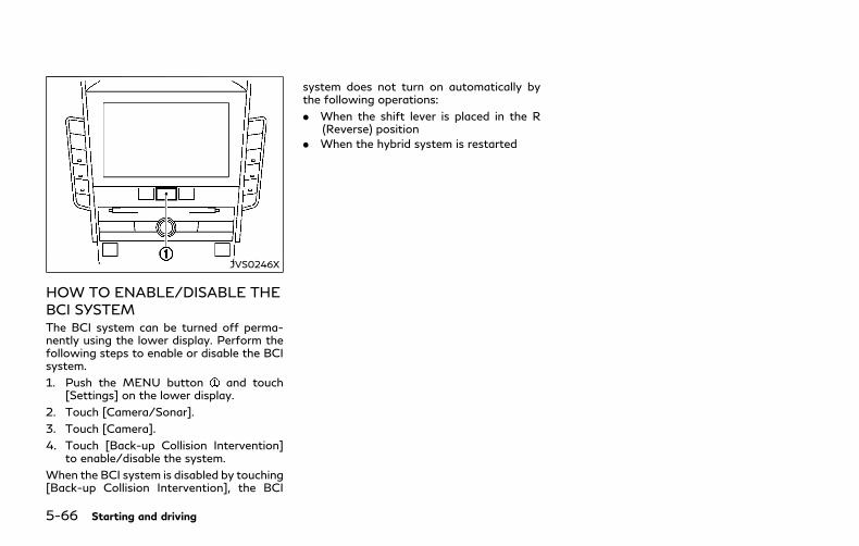
5-66 Starting and driving
JVS0246X
HOW TO ENABLE/DISABLE THEBCI SYSTEMThe BCI system can be turned off perma-nently using the lower display. Perform thefollowing steps to enable or disable the BCIsystem.
1. Push the MENU button and touch[Settings] on the lower display.
2. Touch [Camera/Sonar].
3. Touch [Camera].
4. Touch [Back-up Collision Intervention]to enable/disable the system.
When the BCI system is disabled by touching[Back-up Collision Intervention], the BCI
system does not turn on automatically bythe following operations:
. When the shift lever is placed in the R(Reverse) position
. When the hybrid system is restarted

JVS0479X
BCI SYSTEM LIMITATIONS
WARNING
Listed below are the system limitationsfor the BCI system. Failure to operate
the vehicle in accordance with thesesystem limitations could result in seriousinjury or death.
. Always check your surroundings andturn to check what is behind youbefore backing up.
. The radar sensors detect approach-ing (moving) vehicles. The radar sen-sors cannot detect every object suchas:
— Pedestrians, bicycles, animals orchild operated toy vehicles
— A vehicle that is passing at speedsgreater than approximately 15MPH (24 km/h)
. The radar sensors may not detectapproaching vehicles in certain situa-tions:
— Illustration a. When a vehicleparked next to you obstructs thebeam of the radar sensor.
— Illustration b. When the vehicle isparked in an angled parking space.
— Illustration c. When the vehicle isparked on inclined ground.
— Illustration d.When an approach-ing vehicle turns into your vehi-cle’s parking lot aisle.
— Illustration e. When the angleformed by your vehicle and ap-proaching vehicle is small.
. The following conditions may reducethe ability of the radar sensors todetect other vehicles:
Starting and driving 5-67
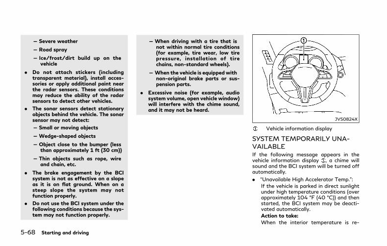
5-68 Starting and driving
— Severe weather
— Road spray
— Ice/frost/dirt build up on thevehicle
. Do not attach stickers (includingtransparent material), install acces-sories or apply additional paint nearthe radar sensors. These conditionsmay reduce the ability of the radarsensors to detect other vehicles.
. The sonar sensors detect stationaryobjects behind the vehicle. The sonarsensor may not detect:
— Small or moving objects
— Wedge-shaped objects
— Object close to the bumper (lessthan approximately 1 ft (30 cm))
— Thin objects such as rope, wireand chain, etc.
. The brake engagement by the BCIsystem is not as effective on a slopeas it is on flat ground. When on asteep slope the system may notfunction properly.
. Do not use the BCI system under thefollowing conditions because the sys-tem may not function properly.
— When driving with a tire that isnot within normal tire conditions(for example, tire wear, low tirepressure, installation of tirechains, non-standard wheels).
— When the vehicle is equippedwithnon-original brake parts or sus-pension parts.
. Excessive noise (for example, audiosystem volume, open vehicle window)will interfere with the chime sound,and it may not be heard.
JVS0824X
Vehicle information display
SYSTEM TEMPORARILY UNA-VAILABLEIf the following message appears in thevehicle information display , a chime willsound and the BCI system will be turned offautomatically.
. “Unavailable High Accelerator Temp.”:
If the vehicle is parked in direct sunlightunder high temperature conditions (overapproximately 104 °F (40 °C)) and thenstarted, the BCI system may be deacti-vated automatically.
Action to take:When the interior temperature is re-

duced, turn off the BCI system and turnit on again.
. “Unavailable Side Radar Obstruction”:
When side radar blockage is detected.
Action to take:When the blockage is removed, turn offthe BCI system and turn it on again.
SYSTEM MALFUNCTIONIf the BCI system malfunctions, it will turnoff automatically, a chimewill sound and BCIsystem “malfunction” warning message willappear in the vehicle information display .
Action to take
Stop the vehicle in a safe location and placethe shift lever in the P (Park) position. Turnthe hybrid system off and restart the hybridsystem. If the warning message continues toappear, have the system checked. It isrecommended you visit an INFINITI retailerfor this service.
JVS1122X
SYSTEM MAINTENANCEThe two radar sensors for the BCI systemare located near the rear bumper. Alwayskeep the area near the radar sensors clean.
The radar sensors may be blocked bytemporary ambient conditions such assplashing water, mist or fog.
The blocked condition may also be caused byobjects such as ice, frost or dirt obstructingthe radar sensors.
Check for and remove objects obstructingthe area around the radar sensors.
Do not attach stickers (including transparentmaterial), install accessories or apply addi-tional paint near the radar sensors.
Do not strike or damage the area around theradar sensors.
It is recommended you visit an INFINITIretailer if the area around the radar sensorsis damaged due to a collision.
Radio frequency statementFor USA
This device complies with part 15 of theFCC Rules.
Operation is subject to the following twoconditions: (1) This device may not causeharmful interference, and (2) this devicemust accept any interference received, in-cluding interference that may cause unde-sired operation.
NOTE:
The manufacturer is not responsible for anyradio or TV interference caused by un-authorized modifications to this equipment.Such modifications could void the user’sauthority to operate the equipment.
For Canada
This device complies with Industry CanadaStandard RSS-310.
Operation is subject to the following twoconditions: (1) This device may not causeharmful interference, and (2) this devicemust accept any interference received, in-cluding interference that may cause unde-
Starting and driving 5-69

5-70 Starting and driving
sired operation.
Frequency of operation: 24.05GHz —24.25GHz
Field Strength: Not greater than 2.5V/mpeak (0.25V/m average) at a distance of 3m
PRECAUTIONS ON CRUISECONTROL. If the cruise control system malfunctions,
it will cancel automatically. The cruiseindicator (green) in the vehicle informa-tion display will then blink to warn thedriver.
. If the engine coolant temperature be-comes excessively high, the cruise con-t r o l s y s t em w i l l b e c a n c e l e dautomatically.
. If the cruise indicator (green) blinks, turnthe cruise control MAIN switch off andhave the system checked. It is recom-mended you visit an INFINITI retailer forthis service.
. The cruise indicator (green) may some-times blink when the cruise controlMAINswitch is turned ON while pushing theSET/COAST (-), RESUME/ACCELER-ATE (+) or CANCEL switch. To properlyset the cruise control system, performthe steps below in the order indicated.
WARNING
Do not use the cruise control whendriving under the following conditions:
. when it is not possible to keep thevehicle at a set speed
. in heavy traffic or in traffic thatvaries in speed
. on winding or hilly roads
. on slippery roads (rain, snow, ice,etc.)
. in very windy areas
Doing so could cause a loss of vehiclecontrol and result in an accident.
CRUISE CONTROL (if so equipped)
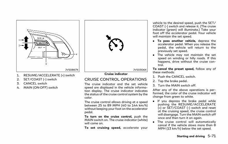
JVS0867X
1. RESUME/ACCELERATE (+) switch
2. SET/COAST (-) switch
3. CANCEL switch
4. MAIN (ON·OFF) switch
JVS0306X
Cruise indicator
CRUISE CONTROL OPERATIONSThe cruise indicator and the set vehiclespeed are displayed in the vehicle informa-tion display. The cruise indicator indicatesthe status of the cruise control system by thecolor.
The cruise control allows driving at a speedbetween 25 to 89 MPH (40 to 144 km/h)without keeping your foot on the acceleratorpedal.
To turn on the cruise control, push theMAIN switch on. The cruise indicator (white)will come on.
To set cruising speed, accelerate your
vehicle to the desired speed, push the SET/COAST (-) switch and release it. (The cruiseindicator (green) will illuminate.) Take yourfoot off the accelerator pedal. Your vehiclewill maintain the set speed.
. To pass another vehicle, depress theaccelerator pedal. When you release thepedal, the vehicle will return to thepreviously set speed.
. The vehicle may not maintain the setspeed on winding or hilly roads. If thishappens, drive without the cruise con-trol.
To cancel the preset speed, follow any ofthese methods:
1. Push the CANCEL switch.
2. Tap the brake pedal.
3. Turn the MAIN switch off.
After any of the above operations is per-formed, the color of the cruise indicator willchange from green to white.
. If you depress the brake pedal whilepushing the RESUME/ACCELERATE(+) or SET/COAST (-) switch and resetat the cruising speed, the cruise controlwill disengage. Turn theMAIN switch offonce and then turn it on again.
. The cruise control will automaticallycancel if the vehicle slows more than 8MPH (13 km/h) below the set speed.
Starting and driving 5-71

5-72 Starting and driving
. If you move the shift lever to N (Neutral)position, the cruise control will be can-celed.
To reset at a faster cruising speed, use oneof the following methods:
. Depress the accelerator pedal. When thevehicle attains the desired speed, pushand release the SET/COAST (-) switch.
. Push and hold the RESUME/ACCELER-ATE (+) switch. When the vehicle attainsthe speed you desire, release the switch.
. Push, then quickly release the RESUME/ACCELERATE (+) switch. Each time youdo this, the set speed will increase byabout 1 MPH (1.6 km/h).
To reset at a slower cruising speed, use oneof the following methods:
. Lightly tap the brake pedal. When thevehicle attains the desired speed, pushthe SET/COAST (-) switch and release it.
. Push and hold the SET/COAST (-)switch. Release the switch when thevehicle slows down to the desired speed.
. Push, then quickly release the SET/COAST (-) switch. Each time you do this,the set speed will decrease by about 1MPH (1.6 km/h).
To resume the preset speed, push andrelease the RESUME/ACCELERATE (+)switch. The vehicle will resume the last setcruising speedwhen the vehicle speed is over
25 MPH (40 km/h).
WARNING
Failure to follow the warnings andinstructions for proper use of the ICCsystem could result in serious injury ordeath.
. ICC is not a collision avoidance orwarning device. For highway use onlyand it is not intended for congestedareas or city driving. Failure to applythe brakes could result in an accident.
. Always observe posted speed limitsand do not set the speed over them.
. Always drive carefully and atten-tively when using either cruise con-trol mode. Read and understand theOwner’s Manual thoroughly beforeusing the cruise control. To avoidserious injury or death, do not relyon the system to prevent accidents orto control the vehicle’s speed inemergency situations. Do not usecruise control except in appropriateroad and traffic conditions.
. In the conventional (fixed speed)cruise control mode, a warning chimewill not sound to warn you if you aretoo close to the vehicle ahead. Payspecial attention to the distancebetween your vehicle and the vehicle
INTELLIGENT CRUISE CONTROL(ICC) (if so equipped)
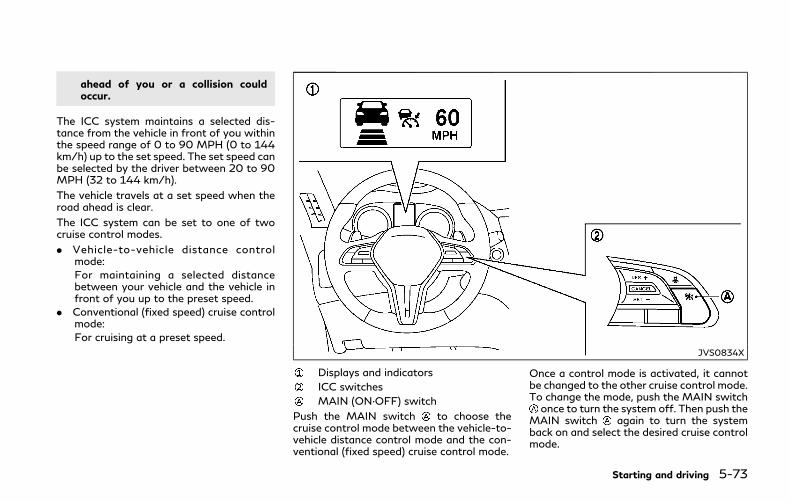
ahead of you or a collision couldoccur.
The ICC system maintains a selected dis-tance from the vehicle in front of you withinthe speed range of 0 to 90 MPH (0 to 144km/h) up to the set speed. The set speed canbe selected by the driver between 20 to 90MPH (32 to 144 km/h).
The vehicle travels at a set speed when theroad ahead is clear.
The ICC system can be set to one of twocruise control modes.
. Vehicle-to-vehicle distance controlmode:
For maintaining a selected distancebetween your vehicle and the vehicle infront of you up to the preset speed.
. Conventional (fixed speed) cruise controlmode:
For cruising at a preset speed.
JVS0834X
Displays and indicators
ICC switches
MAIN (ON·OFF) switch
Push the MAIN switch to choose thecruise control mode between the vehicle-to-vehicle distance control mode and the con-ventional (fixed speed) cruise control mode.
Once a control mode is activated, it cannotbe changed to the other cruise control mode.To change the mode, push the MAIN switchonce to turn the system off. Then push the
MAIN switch again to turn the systemback on and select the desired cruise controlmode.
Starting and driving 5-73
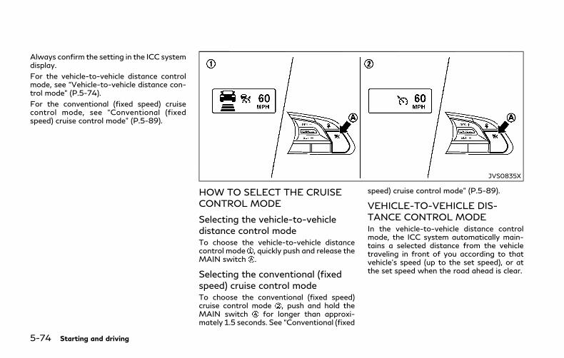
5-74 Starting and driving
Always confirm the setting in the ICC systemdisplay.
For the vehicle-to-vehicle distance controlmode, see “Vehicle-to-vehicle distance con-trol mode” (P.5-74).
For the conventional (fixed speed) cruisecontrol mode, see “Conventional (fixedspeed) cruise control mode” (P.5-89).
JVS0835X
HOW TO SELECT THE CRUISECONTROL MODE
Selecting the vehicle-to-vehicledistance control modeTo choose the vehicle-to-vehicle distancecontrol mode , quickly push and release theMAIN switch .
Selecting the conventional (fixedspeed) cruise control modeTo choose the conventional (fixed speed)cruise control mode , push and hold theMAIN switch for longer than approxi-mately 1.5 seconds. See “Conventional (fixed
speed) cruise control mode” (P.5-89).
VEHICLE-TO-VEHICLE DIS-TANCE CONTROL MODEIn the vehicle-to-vehicle distance controlmode, the ICC system automatically main-tains a selected distance from the vehicletraveling in front of you according to thatvehicle’s speed (up to the set speed), or atthe set speed when the road ahead is clear.
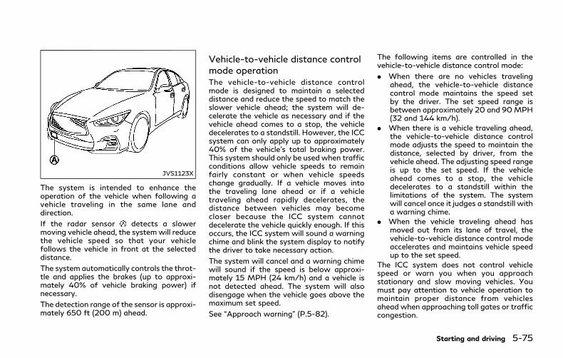
JVS1123X
The system is intended to enhance theoperation of the vehicle when following avehicle traveling in the same lane anddirection.
If the radar sensor detects a slowermoving vehicle ahead, the systemwill reducethe vehicle speed so that your vehiclefollows the vehicle in front at the selecteddistance.
The system automatically controls the throt-tle and applies the brakes (up to approxi-mately 40% of vehicle braking power) ifnecessary.
The detection range of the sensor is approxi-mately 650 ft (200 m) ahead.
Vehicle-to-vehicle distance controlmode operationThe vehicle-to-vehicle distance controlmode is designed to maintain a selecteddistance and reduce the speed to match theslower vehicle ahead; the system will de-celerate the vehicle as necessary and if thevehicle ahead comes to a stop, the vehicledecelerates to a standstill. However, the ICCsystem can only apply up to approximately40% of the vehicle’s total braking power.This system should only be used when trafficconditions allow vehicle speeds to remainfairly constant or when vehicle speedschange gradually. If a vehicle moves intothe traveling lane ahead or if a vehicletraveling ahead rapidly decelerates, thedistance between vehicles may becomecloser because the ICC system cannotdecelerate the vehicle quickly enough. If thisoccurs, the ICC system will sound a warningchime and blink the system display to notifythe driver to take necessary action.
The system will cancel and a warning chimewill sound if the speed is below approxi-mately 15 MPH (24 km/h) and a vehicle isnot detected ahead. The system will alsodisengage when the vehicle goes above themaximum set speed.
See “Approach warning” (P.5-82).
The following items are controlled in thevehicle-to-vehicle distance control mode:
. When there are no vehicles travelingahead, the vehicle-to-vehicle distancecontrol mode maintains the speed setby the driver. The set speed range isbetween approximately 20 and 90MPH(32 and 144 km/h).
. When there is a vehicle traveling ahead,the vehicle-to-vehicle distance controlmode adjusts the speed to maintain thedistance, selected by driver, from thevehicle ahead. The adjusting speed rangeis up to the set speed. If the vehicleahead comes to a stop, the vehicledecelerates to a standstill within thelimitations of the system. The systemwill cancel once it judges a standstill witha warning chime.
. When the vehicle traveling ahead hasmoved out from its lane of travel, thevehicle-to-vehicle distance control modeaccelerates and maintains vehicle speedup to the set speed.
The ICC system does not control vehiclespeed or warn you when you approachstationary and slow moving vehicles. Youmust pay attention to vehicle operation tomaintain proper distance from vehiclesahead when approaching toll gates or trafficcongestion.
Starting and driving 5-75

5-76 Starting and driving
SSD0254
When driving on the freeway at a set speedand approaching a slower traveling vehicleahead, the ICC system will adjust the speedto maintain the distance, selected by thedriver, from the vehicle ahead. If the vehicleahead changes lanes or exits the freeway,the ICC system will accelerate and maintainthe speed up to the set speed. Pay attentionto the driving operation to maintain controlof the vehicle as it accelerates to the setspeed.
The vehicle may not maintain the set speedon winding or hilly roads. If this occurs, youwill have to manually control the vehiclespeed.
Normally when controlling the distance to a
vehicle ahead, this system automaticallyaccelerates or decelerates your vehicle ac-cording to the speed of the vehicle ahead.Depress the accelerator to properly accel-erate your vehicle when acceleration isrequired for a lane change. Depress thebrake pedal when deceleration is requiredto maintain a safe distance to the vehicleahead due to its sudden braking or if avehicle cuts in. Always stay alert when usingthe ICC system.
JVS0836X
Vehicle-to-vehicle distance controlmode switchesThe system is operated by a MAIN switchand four control switches, all mounted onthe steering wheel.
1. RESUME/ACCELERATE (+) switch:
Resumes set speed or increases speedincrementally.
2. SET/COAST (-) switch:
Sets desired cruise speed, reduces speedincrementally.
3. CANCEL switch:
Deactivates the system without erasingthe set speed.

4. MAIN switch:
Master switch to activate the system
5. DISTANCE switch:
Changes the vehicle’s following distance:. Long. Middle. Short
JVS0220X
Vehicle-to-vehicle distance controlmode display and indicatorsThe display is located between the speed-ometer and tachometer.
1. This indicator indicates the ICC systemstatus depending on a color.. Intelligent Cruise Control system ON
indicator (white):
Indicates that theMAIN switch is ON.. Intelligent Cruise Control system set
indicator (green):
Indicates that cruising speed is set. Intelligent Cruise Control system
warning (orange):
Indicates that there is a malfunction inthe ICC system.
2. Vehicle ahead detection indicator:
Indicates whether it detects a vehicle infront of you.
3. Set vehicle speed indicator:
Indicates the set vehicle speed.
For Canadian models, the speed is dis-played in km/h.
4. Set distance indicator:
Displays the selected distance betweenvehicles set with the DISTANCE switch.
Starting and driving 5-77

5-78 Starting and driving
JVS0837X
Operating vehicle-to-vehicle dis-tance control modeTo turn on the cruise control, quickly pushand release the MAIN switch on. TheIntelligent Cruise Control (ICC) system ONindicator (white), set distance indicator andset vehicle speed indicator come on and in astandby state for setting.
JVS0838X
To set cruising speed, accelerate yourvehicle to the desired speed, push the SET/COAST (-) switch and release it. (The ICCsystem set indicator (green), vehicle aheaddetection indicator, set distance indicatorand set vehicle speed indicator come on.)Take your foot off the accelerator pedal.Your vehicle will maintain the set speed.
JVS0214X
When the SET/COAST (-) switch is pushedunder the following conditions, the systemcannot be set and the ICC indicators willblink for approximately 2 seconds:
. When traveling below 20 MPH (32km/h) and the vehicle ahead is notdetected
. When the shift lever is not in the D (Drive)or manual shift mode
. When the parking brake is applied
. When the brakes are operated by thedriver
When the SET/COAST (-) switch is pushedunder the following conditions, the systemcannot be set.
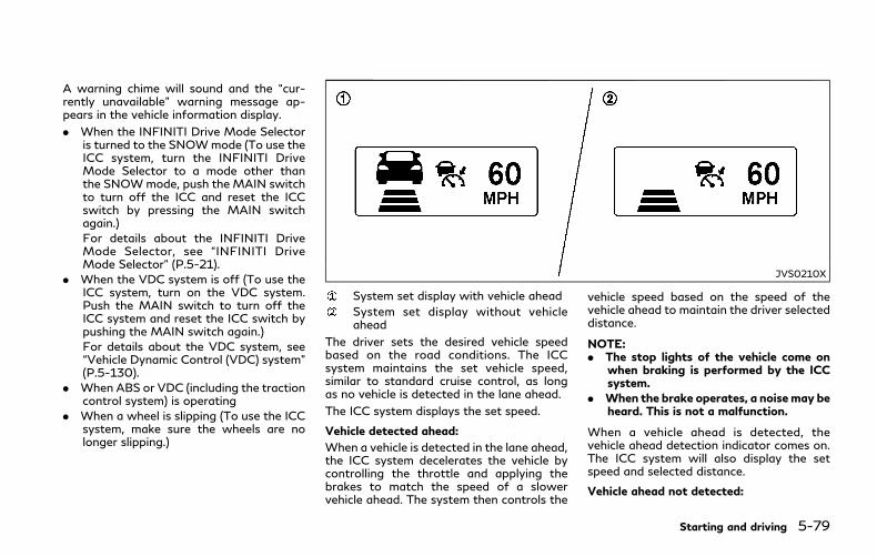
A warning chime will sound and the “cur-rently unavailable” warning message ap-pears in the vehicle information display.
. When the INFINITI Drive Mode Selectoris turned to the SNOWmode (To use theICC system, turn the INFINITI DriveMode Selector to a mode other thanthe SNOWmode, push the MAIN switchto turn off the ICC and reset the ICCswitch by pressing the MAIN switchagain.)
For details about the INFINITI DriveMode Selector, see “INFINITI DriveMode Selector” (P.5-21).
. When the VDC system is off (To use theICC system, turn on the VDC system.Push the MAIN switch to turn off theICC system and reset the ICC switch bypushing the MAIN switch again.)
For details about the VDC system, see“Vehicle Dynamic Control (VDC) system”(P.5-130).
. When ABS or VDC (including the tractioncontrol system) is operating
. When a wheel is slipping (To use the ICCsystem, make sure the wheels are nolonger slipping.)
JVS0210X
System set display with vehicle ahead
System set display without vehicleahead
The driver sets the desired vehicle speedbased on the road conditions. The ICCsystem maintains the set vehicle speed,similar to standard cruise control, as longas no vehicle is detected in the lane ahead.
The ICC system displays the set speed.
Vehicle detected ahead:
When a vehicle is detected in the lane ahead,the ICC system decelerates the vehicle bycontrolling the throttle and applying thebrakes to match the speed of a slowervehicle ahead. The system then controls the
vehicle speed based on the speed of thevehicle ahead to maintain the driver selecteddistance.
NOTE:. The stop lights of the vehicle come on
when braking is performed by the ICCsystem.
. When the brake operates, a noisemay beheard. This is not a malfunction.
When a vehicle ahead is detected, thevehicle ahead detection indicator comes on.The ICC system will also display the setspeed and selected distance.
Vehicle ahead not detected:
Starting and driving 5-79
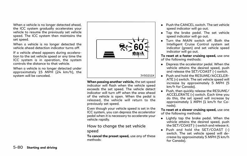
5-80 Starting and driving
When a vehicle is no longer detected ahead,the ICC system gradually accelerates yourvehicle to resume the previously set vehiclespeed. The ICC system then maintains theset speed.
When a vehicle is no longer detected thevehicle ahead detection indicator turns off.
If a vehicle ahead appears during accelera-tion to the set vehicle speed or any time theICC system is in operation, the systemcontrols the distance to that vehicle.
When a vehicle is no longer detected underapproximately 15 MPH (24 km/h), thesystem will be canceled. JVS0211X
When passing another vehicle, the set speedindicator will flash when the vehicle speedexceeds the set speed. The vehicle detectindicator will turn off when the area aheadof the vehicle is open. When the pedal isreleased, the vehicle will return to thepreviously set speed.
Even though your vehicle speed is set in theICC system, you can depress the acceleratorpedal when it is necessary to accelerate yourvehicle rapidly.
How to change the set vehiclespeedTo cancel the preset speed, use any of thesemethods:
. Push the CANCEL switch. The set vehiclespeed indicator will go out.
. Tap the brake pedal. The set vehiclespeed indicator will go out.
. Turn the MAIN switch off. Both theIntelligent Cruise Control system setindicator (green) and set vehicle speedindicator will go out.
To reset at a faster cruising speed, use oneof the following methods:
. Depress the accelerator pedal. When thevehicle attains the desired speed, pushand release the SET/COAST (-) switch.
. Push and hold the RESUME/ACCELER-ATE (+) switch. The set vehicle speed willincrease by approximately 5 MPH (5km/h for Canada).
. Push, then quickly release the RESUME/ACCELERATE (+) switch. Each time youdo this, the set speed will increase byapproximately 1 MPH (1 km/h for Ca-nada).
To reset at a slower cruising speed, use oneof the following methods:
. Lightly tap the brake pedal. When thevehicle attains the desired speed, pushthe SET/COAST (-) switch and release it.
. Push and hold the SET/COAST (-)switch. The set vehicle speed will de-crease by approximately 5 MPH (5 km/hfor Canada).
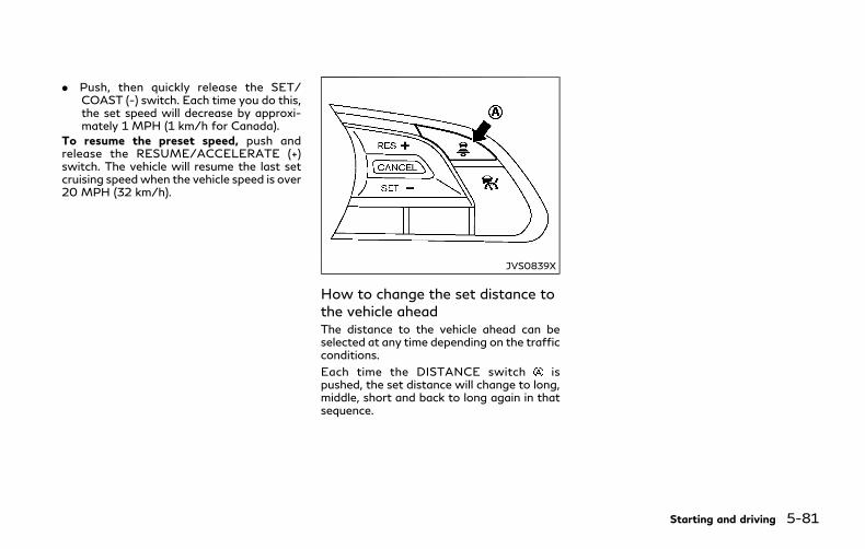
. Push, then quickly release the SET/COAST (-) switch. Each time you do this,the set speed will decrease by approxi-mately 1 MPH (1 km/h for Canada).
To resume the preset speed, push andrelease the RESUME/ACCELERATE (+)switch. The vehicle will resume the last setcruising speedwhen the vehicle speed is over20 MPH (32 km/h).
JVS0839X
How to change the set distance tothe vehicle aheadThe distance to the vehicle ahead can beselected at any time depending on the trafficconditions.
Each time the DISTANCE switch ispushed, the set distance will change to long,middle, short and back to long again in thatsequence.
Starting and driving 5-81

5-82 Starting and driving
JVS0250M
. The distance to the vehicle ahead willchange according to the vehicle speed.The higher the vehicle speed, the longerthe distance.
. If the INFINITI Direct Response Hybrid®
System is stopped, the set distancebecomes “long”. (Each time the hybrid
system is started, the initial settingbecomes “long”.)
Approach warningIf your vehicle comes closer to the vehicleahead due to rapid deceleration of thatvehicle or if another vehicle cuts in, the
system warns the driver with the chime andICC system display. Decelerate by depres-sing the brake pedal to maintain a safevehicle distance if:
. The chime sounds.
. The vehicle ahead detection indicator andset distance indicator blink.
The warning chime may not sound in somecases when there is a short distance be-tween vehicles. Some examples are:
. When the vehicles are traveling at thesame speed and the distance betweenvehicles is not changing
. When the vehicle ahead is travelingfaster and the distance between vehiclesis increasing
. When a vehicle cuts in near your vehicle
The warning chime will not sound when:
. Your vehicle approaches other vehiclesthat are parked or moving slowly.
. The accelerator pedal is depressed, over-riding the system.
NOTE:
The approach warning chime may soundand the system display may blink when theradar sensor detects objects on the side ofthe vehicle or on the side of the road. Thismay cause the ICC system to decelerate oraccelerate the vehicle. The radar sensor maydetect these objects when the vehicle is

driven on winding roads, narrow roads, hillyroads or when entering or exiting a curve. Inthese cases you will have to manuallycontrol the proper distance ahead of yourvehicle.
Also, the sensor sensitivity can be affectedby vehicle operation (steering maneuver ordriving position in the lane) or traffic orvehicle condition (for example, if a vehicle isbeing driven with some damage).
Automatic cancellationA chime sounds under the following condi-tions and the control is automatically can-celed.
. When the vehicle ahead is not detectedand your vehicle is traveling below thespeed of 15 MPH (24 km/h)
. When the system judges the vehicle is atstandstill
. When the shift lever is not in the Dposition or manual shift mode
. When the parking brake is applied
. When the INFINITI Drive Mode Selectoris turned to the SNOW mode
. When the VDC system is turned off
. When ABS or VDC (including the tractioncontrol system) operates
. When distance measurement becomesimpaired due to adhesion of dirt orobstruction to the sensor
. When a wheel slips
. When the radar signal is temporarilyinterrupted
Vehicle-to-vehicle distance controlmode limitations
WARNING
Listed below are the system limitationsfor the ICC system. Failure to operatethe vehicle in accordance with thesesystem limitations could result in seriousinjury or death.
. The system is primarily intended foruse on straight, dry, open roads withlight traffic. It is not advisable to usethe system in city traffic or con-gested areas.
. This system will not adapt automati-cally to road conditions. This systemshould be used in evenly flowingtraffic. Do not use the system onroads with sharp curves, or on icyroads, in heavy rain or in fog.
. As there is a performance limit to thedistance control function, never relysolely on the ICC system. This systemdoes not correct careless, inattentiveor absent-minded driving, or over-
come poor visibility in rain, fog, orother bad weather. Decelerate thevehicle speed by depressing the brakepedal, depending on the distance tothe vehicle ahead and the surround-ing circumstances in order to main-tain a safe distance between vehicles.
. If the vehicle ahead comes to a stop,the vehicle decelerates to a standstillwithin the limitations of the system.The system will cancel once it judgesthat the vehicle has come to astandstill and sound a warning chime.To prevent the vehicle from moving,the driver must depress the brakepedal.
. Always pay attention to the opera-tion of the vehicle and be ready tomanually control the proper follow-ing distance. The vehicle-to-vehicledistance control mode of the ICCsystem may not be able to maintainthe selected distance between vehi-cles (following distance) or selectedvehicle speed under some circum-stances.
. The system may not detect thevehicle in front of you in certain roador weather conditions. To avoid ac-cidents, never use the ICC systemunder the following conditions:
Starting and driving 5-83
5-84 Starting and driving
— On roads where the traffic isheavy or there are sharp curves
— On slippery road surfaces such ason ice or snow, etc.
— During bad weather (rain, fog,snow, etc.)
— When rain, snow or dirt adhere tothe system sensor
— On steep downhill roads (thevehicle may go beyond the setvehicle speed and frequent brak-ing may result in overheating thebrakes)
— On repeated uphill and downhillroads
— When traffic conditions make itdifficult to keep a proper distancebetween vehicles because of fre-quent acceleration or deceleration
. In some road or traffic conditions, avehicle or object can unexpectedlycome into the sensor detection zoneand cause automatic braking. Youmay need to control the distancefrom other vehicles using the accel-erator pedal. Always stay alert andavoid using the ICC system when it isnot recommended in this section.
The radar sensor will not detect the follow-ing objects:
. Stationary and slow moving vehicles
. Pedestrians or objects in the roadway
. Oncoming vehicles in the same lane
. Motorcycles traveling offset in the travellane
The sensor generally detects the signalsreturned from the vehicle ahead. Therefore,if the sensor cannot detect the reflectionfrom the vehicle ahead, the ICC system maynot maintain the selected distance.
The following are some conditions in whichthe sensor cannot detect the signals:
. When the snow or road spray fromtraveling vehicles reduces the sensor’svisibility
. When excessively heavy baggage isloaded in the rear seat or the trunk ofyour vehicle
The ICC system is designed to automaticallycheck the sensor’s operation within thelimitation of the system. When the sensoris covered with dirt or is obstructed, thesystem will automatically be canceled. If thesensor is covered with ice, a transparent ortranslucent vinyl bag, etc., the ICC systemmay not detect them. In these instances, thevehicle-to-vehicle distance control modemay not cancel and may not be able tomaintain the selected following distance
from the vehicle ahead. Be sure to checkand clean the sensor regularly.
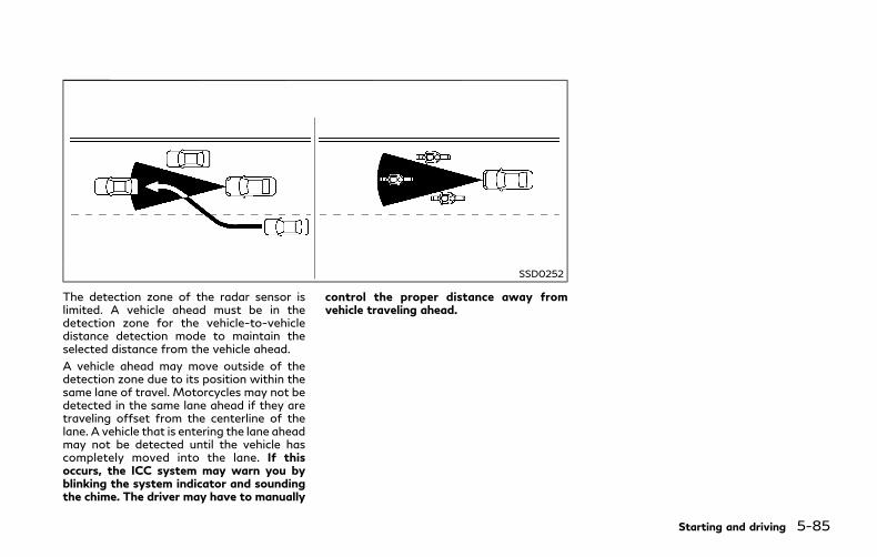
SSD0252
The detection zone of the radar sensor islimited. A vehicle ahead must be in thedetection zone for the vehicle-to-vehicledistance detection mode to maintain theselected distance from the vehicle ahead.
A vehicle ahead may move outside of thedetection zone due to its position within thesame lane of travel. Motorcycles may not bedetected in the same lane ahead if they aretraveling offset from the centerline of thelane. A vehicle that is entering the lane aheadmay not be detected until the vehicle hascompletely moved into the lane. If thisoccurs, the ICC system may warn you byblinking the system indicator and soundingthe chime. The driver may have to manually
control the proper distance away fromvehicle traveling ahead.
Starting and driving 5-85
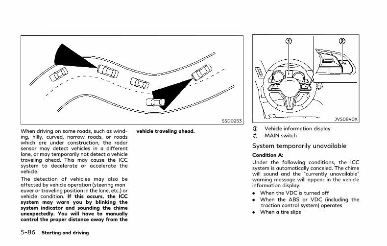
5-86 Starting and driving
SSD0253
When driving on some roads, such as wind-ing, hilly, curved, narrow roads, or roadswhich are under construction, the radarsensor may detect vehicles in a differentlane, or may temporarily not detect a vehicletraveling ahead. This may cause the ICCsystem to decelerate or accelerate thevehicle.
The detection of vehicles may also beaffected by vehicle operation (steering man-euver or traveling position in the lane, etc.) orvehicle condition. If this occurs, the ICCsystem may warn you by blinking thesystem indicator and sounding the chimeunexpectedly. You will have to manuallycontrol the proper distance away from the
vehicle traveling ahead.
JVS0840X
Vehicle information display
MAIN switch
System temporarily unavailable
Condition A:
Under the following conditions, the ICCsystem is automatically canceled. The chimewill sound and the “currently unavailable”warning message will appear in the vehicleinformation display.
. When the VDC is turned off
. When the ABS or VDC (including thetraction control system) operates
. When a tire slips

. When the INFINITI Drive Mode Selectoris turned to the SNOW mode
. When the radar signal is temporarilyinterrupted
Action to take:
When the conditions listed above are nolonger present, turn the ICC system back onto use the system.
JVS0221X
ICC system warning
Condition B:
Under the following conditions, making itimpossible to detect a vehicle ahead, the ICCsystem is automatically canceled.
The chime will sound, the ICC systemwarning (orange) and the “front radar ob-struction” warning message will appear inthe vehicle information display.
. When the radar sensor area of the frontbumper is covered with dirt or is ob-structed
Action to take:
If the warning (orange) or warning messageappears, stop the vehicle in a safe place,place the shift lever in the P (Park) position
and turn the hybrid system off. When theradar signal is temporarily interrupted, cleanthe sensor area of the front bumper andrestart the hybrid system. If the warning(orange) or warning message continues tobe displayed, have the system checked. It isrecommended you visit an INFINITI retailerfor this service.
. When driving on roads with limited roadstructures or buildings (for example, longbridges, deserts, snow fields, driving nextto long walls)
Action to take:
When the above conditions no longer exist,the ICC system will resume automatically.
Condition C:
When the ICC system is not operatingproperly, the chime sounds and the ICCsystem warning (orange) will appear.
Action to take:
If the warning appears, stop the vehicle in asafe place and place the shift lever in the P(Park) position. Turn the hybrid system off,restart the hybrid system, resume drivingand set the ICC system again.
If it is not possible to set the system or thewarning stays on, it may indicate that theICC system is malfunctioning. Although thevehicle is still driveable under normal con-ditions, have the vehicle checked. It is
Starting and driving 5-87
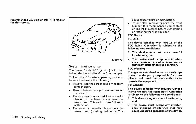
5-88 Starting and driving
recommended you visit an INFINITI retailerfor this service.
JVS1123X
System maintenanceThe sensor for the ICC system is locatedbehind the lower grille of the front bumper.
To keep the ICC system operating properly,be sure to observe the following:
. Always keep the sensor area of the frontbumper clean.
. Do not strike or damage the areas aroundthe sensor.
. Do not cover or attach stickers or similarobjects on the front bumper near thesensor area. This could cause failure ormalfunction.
. Do not attach metallic objects near thesensor area (brush guard, etc.). This
could cause failure or malfunction.
. Do not alter, remove or paint the frontbumper. It is recommended you contactan INFINITI retailer before customizingor restoring the front bumper.
FCC Notice:
For USA:
This device complies with Part 15 of theFCC Rules. Operation is subject to thefollowing two conditions:
1. This device may not cause harmfulinterference, and
2. This device must accept any interfer-ence received, including interferencethat may cause undesired operation.
FCC Warning
Changes or modification not expressly ap-proved by the party responsible for com-pliance could void the user’s authority tooperate the equipment.
For Canada:
This device complies with Industry Canadalicence-exempt RSS standard(s). Operationis subject to the following two conditions:
1. This device may not cause interference,and
2. This device must accept any interfer-ence, including interference that maycause undesired operation of the device.
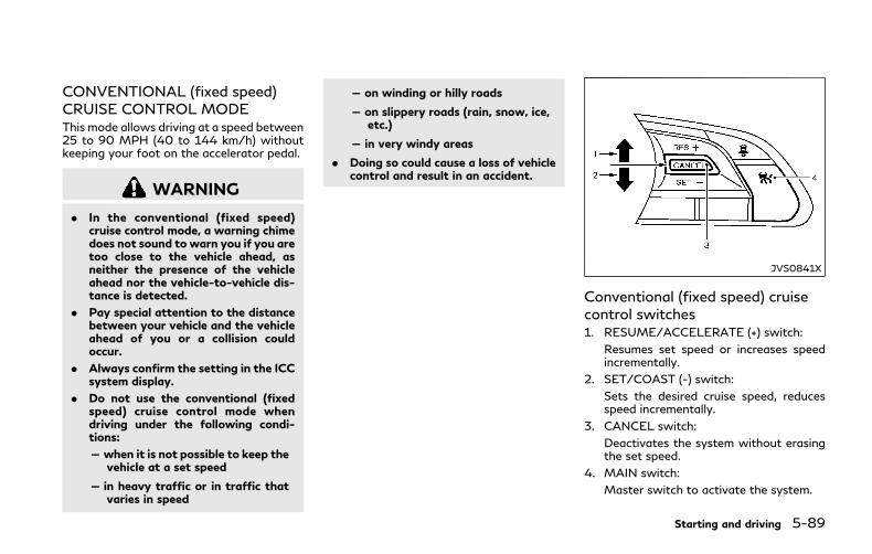
CONVENTIONAL (fixed speed)CRUISE CONTROL MODEThis mode allows driving at a speed between25 to 90 MPH (40 to 144 km/h) withoutkeeping your foot on the accelerator pedal.
WARNING
. In the conventional (fixed speed)cruise control mode, a warning chimedoes not sound to warn you if you aretoo close to the vehicle ahead, asneither the presence of the vehicleahead nor the vehicle-to-vehicle dis-tance is detected.
. Pay special attention to the distancebetween your vehicle and the vehicleahead of you or a collision couldoccur.
. Always confirm the setting in the ICCsystem display.
. Do not use the conventional (fixedspeed) cruise control mode whendriving under the following condi-tions:
— when it is not possible to keep thevehicle at a set speed
— in heavy traffic or in traffic thatvaries in speed
— on winding or hilly roads
— on slippery roads (rain, snow, ice,etc.)
— in very windy areas
. Doing so could cause a loss of vehiclecontrol and result in an accident.
JVS0841X
Conventional (fixed speed) cruisecontrol switches1. RESUME/ACCELERATE (+) switch:
Resumes set speed or increases speedincrementally.
2. SET/COAST (-) switch:
Sets the desired cruise speed, reducesspeed incrementally.
3. CANCEL switch:
Deactivates the system without erasingthe set speed.
4. MAIN switch:
Master switch to activate the system.
Starting and driving 5-89

5-90 Starting and driving
JVS0301X
Conventional (fixed speed) cruisecontrol mode display and indicatorsThe display is located in the vehicle informa-tion display.
1. Cruise indicator:
This indicator indicates the condition ofICC system depending on a color.. Cruise control ON indicator (white):
Indicates that theMAIN switch is ON.. Cruise control set indicator (green):
Displays while the vehicle speed iscontrolled by the conventional (fixedspeed) cruise control mode of the ICCsystem.
. Cruise control system warning (or-ange):
Indicates that there is a malfunction inthe ICC system.
2. Set vehicle speed indicator:
This indicator indicates the set vehiclespeed.
For Canadian models, the speed is dis-played in km/h.
JVS0842X
Operating conventional (fixedspeed) cruise control modeTo turn on the conventional (fixed speed)cruise control mode, push and hold theMAIN switch for longer than about 1.5seconds.
When pushing the MAIN switch on, theconventional (fixed speed) cruise controlmode display and indicators are displayedin the vehicle information display. After youhold the MAIN switch on for longer thanabout 1.5 seconds, the ICC system displayturns off. The cruise indicator appears. Youcan now set your desired cruising speed.Pushing the MAIN switch again will turn the

system completely off.
When the ignition switch is placed in theOFF position, the system is also automati-cally turned off.
To use the ICC system again, quickly pushand release the MAIN switch (vehicle-to-vehicle distance control mode) or push andhold it (conventional cruise control mode)again to turn it on.
When the Distance Control Assist (DCA)system is on, the conventional (fixed speed)cruise control mode cannot be turned oneven though the MAIN switch is pushed andheld.
To turn on the conventional (fixed speed)cruise control mode, turn off the DCAsystem. See “Distance Control Assist(DCA)” (P.5-93).
CAUTION
To avoid accidentally engaging cruisecontrol, make sure to turn the MAINswitch off when not using the ICCsystem.
JVS0843X
To set cruising speed, accelerate yourvehicle to the desired speed, push the SET/COAST (-) switch and release it. (The colorof the cruise indicator changes to green andset vehicle speed indicator comes on.) Takeyour foot off the accelerator pedal. Yourvehicle will maintain the set speed.
. To pass another vehicle, depress theaccelerator pedal. When you release thepedal, the vehicle will return to thepreviously set speed.
. The vehicle may not maintain the setspeed when going up or down steep hills.If this happens, manually maintain vehi-cle speed.
To cancel the preset speed, use any of thefollowing methods:
1. Push the CANCEL switch. The vehiclespeed indicator will turn off.
2. Tap the brake pedal. The vehicle speedindicator will turn off.
3. Turn the MAIN switch off. Both thecruise indicator and vehicle speed indi-cator will turn off.
To reset at a faster cruising speed, use oneof the following three methods:
1. Depress the accelerator pedal. When thevehicle attains the desired speed, pushand release the SET/COAST (-) switch.
2. Push and hold the RESUME/ACCELER-ATE (+) switch. When the vehicle attainsthe desired speed, release the switch.
3. Push, then quickly release the RESUME/ACCELERATE (+) switch. Each time youdo this, the set speed will increase byabout 1 MPH (1.6 km/h).
To reset at a slower cruising speed, use oneof the following three methods:
1. Lightly tap the brake pedal. When thevehicle attains the desired speed, pushthe SET/COAST (-) switch and release it.
2. Push and hold the SET/COAST (-)switch. Release the switch when thevehicle slows down to the desired speed.
Starting and driving 5-91

5-92 Starting and driving
3. Push, then quickly release the SET/COAST (-) switch. Each time you do this,the set speed will decrease by about 1MPH (1.6 km/h).
To resume the preset speed, push andrelease the RESUME/ACCELERATE (+)switch. The vehicle will resume the last setcruising speedwhen the vehicle speed is over25 MPH (40 km/h).
System temporarily unavailableA chime sounds under the following condi-tions and the control is automatically can-celed.
. When the vehicle slows down more than8 MPH (13 km/h) below the set speed
. When the shift lever is not in the D (Drive)or manual shift mode
. When the parking brake is applied.
. When the VDC operates (including thetraction control system)
. When a wheel slips
JVS0306X
WarningWhen the system is not operating properly,the chime sounds and the color of the cruiseindicator will change to orange.
Action to take:
If the color of the cruise indicator changes toorange, stop the vehicle in a safe place andplace the shift lever in the P (Park) position.Turn the hybrid system off, restart thehybrid system, resume driving and thenperform the setting again.
If it is not possible to set or the indicatorstays on, it may indicate that the system ismalfunctioning. Although the vehicle is stilldriveable under normal conditions, have the
vehicle checked. It is recommended you visitan INFINITI retailer for this service.
WARNING
Failure to follow the warnings andinstructions for proper use of the DCAsystem could result in serious personalinjury or death.
. Always drive carefully and atten-tively when using the DCA system.Read and understand the Owner’sManual thoroughly before using theDCA system. To avoid serious injuryor death, do not rely on the system toprevent accidents or to control thevehicle’s speed in emergency situa-tions. Do not use the DCA systemexcept in appropriate road and trafficconditions.
. This system is only an aid to assist thedriver and is not a collisionwarning oravoidance device. It is the driver’sresponsibility to stay alert, drivesafely and be in control of the vehicleat all times.
. As there is a performance limit to thedistance control function, never relysolely on the DCA system. This sys-tem does not correct careless, inat-tentive or absent-minded driving, orovercome poor visibility in rain, fog,or other bad weather. Decelerate the
vehicle speed by depressing the brakepedal, depending on the distance tothe vehicle ahead and the surround-ing circumstances in order to main-tain a safe distance between vehicles.
. Always pay attention to the opera-tion of the vehicle and be ready tomanually decelerate to maintain theproper following distance. The DCAsystem may not be able to deceleratethe vehicle under some circum-stances.
. This system only brakes and movesthe accelerator pedal upward to helpassist the driver to maintain a follow-ing distance from the vehicle ahead.Acceleration should be operated bythe driver.
. The DCA system does not controlvehicle speed or warn you when youapproach stationary and slowmovingvehicles. You must pay attention tovehicle operation to maintain properdistance from vehicles ahead.
. The DCA system automatically de-celerates your vehicle to help assistthe driver to maintain a followingdistance from the vehicle ahead.Manually brake when deceleration isrequired to maintain a safe distanceupon sudden braking by the vehicle
ahead or when a vehicle suddenlyappears in front of you. Always stayalert when using the DCA system.
. If the vehicle ahead comes to a stop,the vehicle decelerates to a standstillwithin the limitations of the system.The systemwill cancel with a warningchime once it judges that the vehiclehas come to a standstill. To preventthe vehicle from moving, the drivermust depress the brake pedal.
Starting and driving 5-93
DISTANCE CONTROL ASSIST(DCA) (if so equipped)
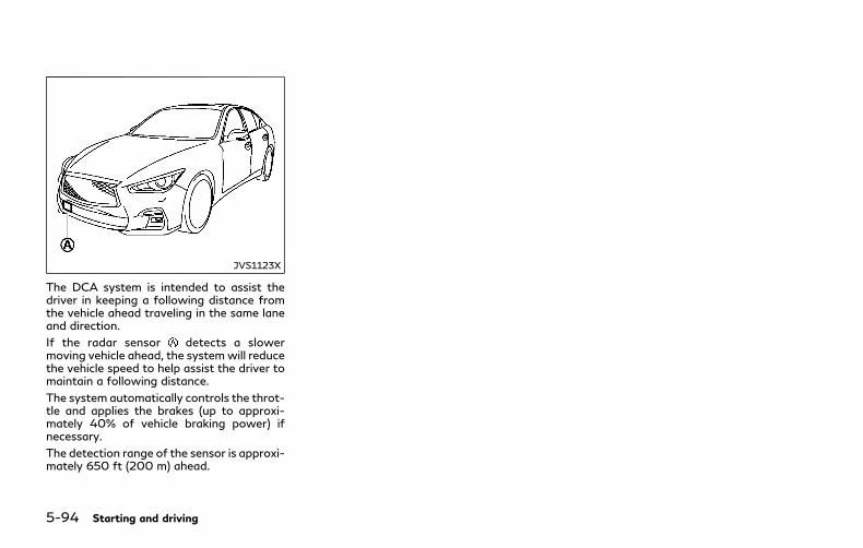
5-94 Starting and driving
JVS1123X
The DCA system is intended to assist thedriver in keeping a following distance fromthe vehicle ahead traveling in the same laneand direction.
If the radar sensor detects a slowermoving vehicle ahead, the systemwill reducethe vehicle speed to help assist the driver tomaintain a following distance.
The system automatically controls the throt-tle and applies the brakes (up to approxi-mately 40% of vehicle braking power) ifnecessary.
The detection range of the sensor is approxi-mately 650 ft (200 m) ahead.
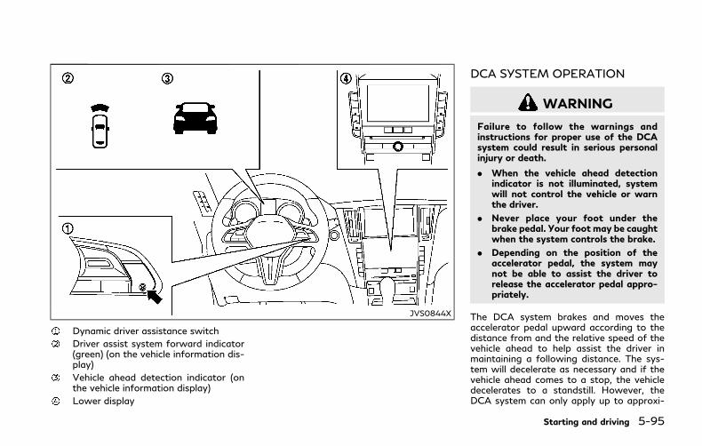
JVS0844X
Dynamic driver assistance switch
Driver assist system forward indicator(green) (on the vehicle information dis-play)
Vehicle ahead detection indicator (onthe vehicle information display)
Lower display
DCA SYSTEM OPERATION
WARNING
Failure to follow the warnings andinstructions for proper use of the DCAsystem could result in serious personalinjury or death.
. When the vehicle ahead detectionindicator is not illuminated, systemwill not control the vehicle or warnthe driver.
. Never place your foot under thebrake pedal. Your foot may be caughtwhen the system controls the brake.
. Depending on the position of theaccelerator pedal, the system maynot be able to assist the driver torelease the accelerator pedal appro-priately.
The DCA system brakes and moves theaccelerator pedal upward according to thedistance from and the relative speed of thevehicle ahead to help assist the driver inmaintaining a following distance. The sys-tem will decelerate as necessary and if thevehicle ahead comes to a stop, the vehicledecelerates to a standstill. However, theDCA system can only apply up to approxi-
Starting and driving 5-95
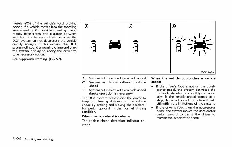
5-96 Starting and driving
mately 40% of the vehicle’s total brakingpower. If a vehicle moves into the travelinglane ahead or if a vehicle traveling aheadrapidly decelerates, the distance betweenvehicles may become closer because theDCA system cannot decelerate the vehiclequickly enough. If this occurs, the DCAsystem will sound a warning chime and blinkthe system display to notify the driver totake necessary action.
See “Approach warning” (P.5-97).
JVS0244X
System set display with a vehicle ahead
System set display without a vehicleahead
System set display with a vehicle ahead(brake operation is necessary)
The DCA system helps assist the driver tokeep a following distance to the vehicleahead by braking and moving the accelera-tor pedal upward in the normal drivingcondition.
When a vehicle ahead is detected:
The vehicle ahead detection indicator ap-pears.
When the vehicle approaches a vehicleahead:
. If the driver’s foot is not on the accel-erator pedal, the system activates thebrakes to decelerate smoothly as neces-sary. If the vehicle ahead comes to astop, the vehicle decelerates to a stand-still within the limitations of the system.
. If the driver’s foot is on the acceleratorpedal, the system moves the acceleratorpedal upward to assist the driver torelease the accelerator pedal.

When brake operation by the driver isrequired:
The system alerts the driver by a warningchime and blinking the vehicle ahead detec-tion indicator. If the driver’s foot is on theaccelerator pedal after the warning, thesystem moves the accelerator pedal upwardto assist the driver to switch to the brakepedal.
NOTE:. The stop lights of the vehicle come on
when braking is performed by the DCAsystem.
. When the brake operates, a noisemay beheard. This is not a malfunction.
Overriding the system:
The following driver’s operation overridesthe system operation.
. When the driver depresses the accelera-tor pedal even further while the system ismoving the accelerator pedal upward,the DCA system control of the accel-erator pedal is canceled.
. When the driver’s foot is on the accel-erator pedal, the brake control by thesystem is not operated.
. When the driver’s foot is on the brakepedal, neither the brake control nor thealert by the system operates.
. When the Intelligent Cruise Control (ICC)system is set, the DCA system will beinactive.
Approach warningIf your vehicle comes closer to the vehicleahead due to rapid deceleration of thatvehicle or if another vehicle cuts in, thesystem warns the driver with the chime andDCA system display. Decelerate by depres-sing the brake pedal to maintain a safevehicle distance if:
. The chime sounds.
. The vehicle ahead detection indicatorblinks.
. The driver assist system forward indica-tor (orange) blinks.
The warning chime may not sound in somecases when there is a short distance be-tween vehicles. Some examples are:
. When the vehicles are traveling at thesame speed and the distance betweenvehicles is not changing
. When the vehicle ahead is travelingfaster and the distance between vehiclesis increasing
. When a vehicle cuts in near your vehicle
The driver assist system forward indicator(orange) blinks and the warning chime willnot sound when your vehicle approachesvehicles that are parked or moving slowly.
NOTE:
The approach warning chime may soundand the driver assist system forward in-dicator (orange) may blink when the radarsensor detects objects on the side of thevehicle or on the side of the road. This maycause the DCA system to decelerate oraccelerate the vehicle. The radar sensormay detect these objects when the vehicleis driven on winding roads, narrow roads,hilly roads or when entering or exiting acurve. In these cases you will have tomanually control the proper distance aheadof your vehicle.
Also, the sensor sensitivity can be affectedby vehicle operation (steering maneuver ordriving position in the lane) or traffic orvehicle condition (for example, if a vehicle isbeing driven with some damage).
Starting and driving 5-97

5-98 Starting and driving
JVS0845X
Dynamic driver assistance switch
Driver assist system forward indicator(green) (on the vehicle information dis-play)
Lower display
TURNING THE DCA SYSTEM ON/OFFTo turn on the DCA system, push thedynamic driver assistance switch on thesteering wheel after starting the INFINITIDirect Response Hybrid® System. The driverassistance switch indicator in the vehicleinformation display will appear. Push thedynamic driver assistance switch again toturn off the DCA system. The driver assis-tance system switch indicator will turn off.
The system will start to operate after thevehicle speed is above approximately 3MPH(5 km/h).
The dynamic driver assistance switch isused for the DCA, Active Lane Control, LaneDeparture Prevention (LDP) and Blind SpotIntervention® (BSI) systems. When the dy-namic driver assistance switch is pushed,Active Lane Control, LDP and BSI systemswill also turn on or off simultaneously. TheDCA system can be individually set to on oroff on the lower display . If the system isset to off, the system will not turn on even ifthe dynamic driver assistance switch ispushed to on. To set the system to on or offon the display, see “How to enable/disablethe DCA system” (P.5-99).
When the conventional (fixed speed) cruisecontrol mode is operating, the DCA systemwill not operate. (To use the DCA system,

turn the conventional (fixed speed) cruisecontrol mode off, then push the dynamicdriver assistance switch.)
For details about the conventional (fixedspeed) cruise control mode, see “IntelligentCruise Control (ICC)” (P.5-72).
When the hybrid system is turned off, theDCA system is automatically turned off.
JVS0246X
HOW TO ENABLE/DISABLE THEDCA SYSTEMPerform the following steps to enable ordisable the DCA system.
1. Push the MENU button and touch[Driver Assistance] on the lower display.
2. Touch [Forward Assist].
3. Touch [Distance Control Assist] to en-able or disable the system.
JVS0225X
DCA SYSTEM DISPLAY AND IN-DICATORSThe display is located between the speed-ometer and tachometer.
1. Driver assist system forward indicator. Driver assist system forward indicator
(green):
Indicates that the DCA system is ON.. Driver assist system forward indicator
(orange):
Indicates whether there is a malfunc-tion in the DCA system.
2. Vehicle ahead detection indicator:
Indicates whether it detects a vehicle in
Starting and driving 5-99

5-100 Starting and driving
front of you.
DCA SYSTEM LIMITATIONS
WARNING
Listed below are the system limitationsof the DCA system. Failure to operatethe vehicle in accordance with thesesystem limitations could result in seriousinjury or death.
. This system will not adapt automati-cally to road conditions. Do not usethe system on roads with sharpcurves, or on icy roads, in heavy rainor in fog.
. The DCA system will not apply brakecontrol while the driver’s foot is onthe accelerator pedal.
. As there is a performance limit to thedistance control function, never relysolely on the DCA system. This sys-tem does not correct careless, inat-tentive or absent-minded driving, orovercome poor visibility in rain, fog,or other bad weather. Decelerate thevehicle speed by depressing the brakepedal, depending on the distance tothe vehicle ahead and the surround-ing circumstances in order to main-tain a safe distance between vehicles.
. The system may not detect thevehicle in front of you in certain roador weather conditions. To avoid ac-cidents, never use the DCA systemunder the following conditions:
— On roads with sharp curves
— On slippery road surfaces such ason ice or snow, etc.
— During bad weather (rain, fog,snow, etc.)
— When rain, snow or dirt adhere tothe system sensor
— On steep downhill roads (fre-quent braking may result in over-heating the brakes)
— On repeated uphill and downhillroads
. In some road or traffic conditions, avehicle or object can unexpectedlycome into the sensor detection zoneand cause automatic braking. Youmay need to control the distancefrom other vehicles using the accel-erator pedal. Always stay alert andavoid using the DCA system when itis not recommended in this section.
The radar sensor will not detect the follow-ing objects:
. Stationary and slow moving vehicles
. Pedestrians or objects in the roadway
. Oncoming vehicles in the same lane
. Motorcycles traveling offset in the travellane
The following are some conditions in whichthe sensor cannot detect the signals:
. When the snow or road spray fromtraveling vehicles reduces the sensor’svisibility
. When excessively heavy baggage isloaded in the rear seat or the trunk roomof your vehicle
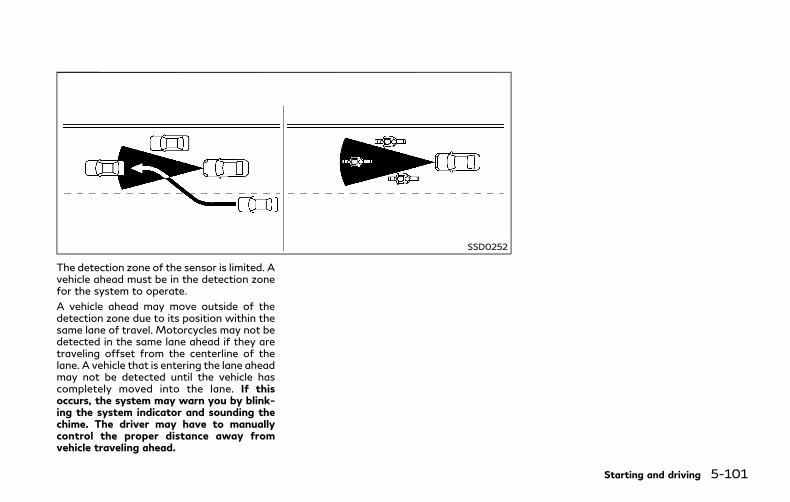
SSD0252
The detection zone of the sensor is limited. Avehicle ahead must be in the detection zonefor the system to operate.
A vehicle ahead may move outside of thedetection zone due to its position within thesame lane of travel. Motorcycles may not bedetected in the same lane ahead if they aretraveling offset from the centerline of thelane. A vehicle that is entering the lane aheadmay not be detected until the vehicle hascompletely moved into the lane. If thisoccurs, the system may warn you by blink-ing the system indicator and sounding thechime. The driver may have to manuallycontrol the proper distance away fromvehicle traveling ahead.
Starting and driving 5-101
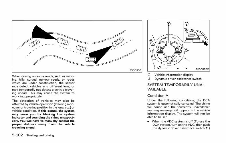
5-102 Starting and driving
SSD0253
When driving on some roads, such as wind-ing, hilly, curved, narrow roads, or roadswhich are under construction, the sensormay detect vehicles in a different lane, ormay temporarily not detect a vehicle travel-ing ahead. This may cause the system towork inappropriately.
The detection of vehicles may also beaffected by vehicle operation (steering man-euver or traveling position in the lane, etc.) orvehicle condition. If this occurs, the systemmay warn you by blinking the systemindicator and sounding the chime unexpect-edly. You will have to manually control theproper distance away from the vehicletraveling ahead.
JVS0826X
Vehicle information display
Dynamic driver assistance switch
SYSTEM TEMPORARILY UNA-VAILABLE
Condition AUnder the following conditions, the DCAsystem is automatically canceled. The chimewill sound and the “currently unavailable”warning message will appear in the vehicleinformation display. The system will not beable to be set.
. When the VDC system is off (To use theDCA system, turn on the VDC, then pushthe dynamic driver assistance switch .)

For details about the VDC system, see“Vehicle Dynamic Control (VDC) system”(P.5-130).
. When the VDC or ABS (including thetraction control system) operates
. When the INFINITI Drive Mode Selectoris turned to the SNOWmode (To use theDCA system, turn the INFINITI DriveMode Selector to a mode other than theSNOW mode, then turn on the dynamicdriver assistance switch .) For detailsabout the INFINITI Drive Mode Selector,see “INFINITI DriveMode Selector” (P.5-21).
. When the radar signal is temporarilyinterrupted
Action to take:
When the conditions listed above are nolonger present, turn the DCA system back onto use the system.
Condition BUnder the following conditions, making itimpossible to detect a vehicle ahead, theDCA system is automatically canceled.
The chime will sound, the driver assistsystem forward indicator (orange) and the“front radar obstruction” warning messagewill appear in the vehicle information display.
. When the radar sensor area of the front
bumper is covered with dirt or is ob-structed
Action to take:
If the driver assist system forward indicator(orange) and the warning message appear,stop the vehicle in a safe place, place theshift lever in the P (Park) position and turnthe hybrid system off. When the radar signalis temporarily interrupted, clean the sensorarea of the front bumper and restart thehybrid system. If the warning messagecontinues to be displayed, have the DCAsystem checked. It is recommended you visitan INFINITI retailer for this service.
. When driving on roads with limited roadstructures or buildings (for example, longbridges, deserts, snow fields, driving nextto long walls)
Action to take:
When the above conditions no longer exist,the DCA system will resume automatically.
SYSTEM MALFUNCTIONWhen the DCA system is not operatingproperly, the chime sounds, the driver assistsystem forward indicator (orange) and thesystem “malfunction” warning message willappear in the vehicle information display.
Action to take:
If the driver assist system forward indicator(orange) and the warning message appear,stop the vehicle in a safe place and place theshift lever in the P (Park) position. Turn thehybrid system off, restart the hybrid system,and turn on the DCA system again.
If it is not possible to set the system or theindicator stays on, it may indicate that thesystem is malfunctioning. Although thevehicle is still driveable under normal con-ditions, have the vehicle checked. It isrecommended you visit an INFINITI retailerfor this service.
SENSOR MAINTENANCEThe sensor for the DCA system is commonwith the Intelligent Cruise Control (ICC)system and is located behind the lower grilleof the front bumper.
For the sensor maintenance, see “IntelligentCruise Control (ICC)” (P.5-72).
FCC Notice:
For USA:
This device complies with Part 15 of theFCC Rules. Operation is subject to thefollowing two conditions:
1. This device may not cause harmfulinterference, and
Starting and driving 5-103

5-104 Starting and driving
2. This device must accept any interfer-ence received, including interferencethat may cause undesired operation.
FCC Warning
Changes or modification not expressly ap-proved by the party responsible for com-pliance could void the user’s authority tooperate the equipment.
For Canada:
This device complies with Industry Canadalicence-exempt RSS standard(s). Operationis subject to the following two conditions:
1. This device may not cause interference,and
2. This device must accept any interfer-ence, including interference that maycause undesired operation of the device.
WARNING
Failure to follow the warnings andinstructions for proper use of the FEBsystem could result in serious personalinjury or death.
. The FEB system is a supplemental aidto the driver. It is not a replacementfor the driver’s attention to trafficconditions or responsibility to drivesafely. It cannot prevent accidentsdue to carelessness or dangerousdriving techniques.
. The FEB system does not function inall driving, traffic, weather and roadconditions.
The FEB system can assist the driver whenthere is a risk of a forward collision with thevehicle ahead in the traveling lane.
JVS1123X
The FEB system uses a radar sensorlocated behind the lower grille of the frontbumper to measure the distance to thevehicle ahead in the same lane.
FORWARDEMERGENCYBRAKING (FEB)

JVS0846X
FEB system warning light (on theinstrument panel)
Indicators and warnings (on the vehicleinformation display)
Driver assist system forward indica-tor
Vehicle ahead detection indicator
Lower display
FEB SYSTEM OPERATIONThe FEB system operates at speeds aboveapproximately 3 MPH (5 km/h).
If a risk of a forward collision is detected, theFEB system will provide the first warning tothe driver by flashing the driver assist systemforward indicator (orange) and the vehicleahead detection indicator (orange) , andproviding an audible warning. In addition,the FEB system pushes the acceleratorpedal up. If the driver releases the accel-erator pedal, then the system applies partialbraking.
If the driver applies the brakes quickly andforcefully after the warning, and the FEBsystem detects that there is still the possi-bility of a forward collision, the system willautomatically increase the braking force.
If a forward collision is imminent and thedriver does not take action, the FEB systemissues the second visual (red) and audiblewarning and automatically applies harderbraking.
NOTE:
The vehicle’s stop lights come on whenbraking is performed by the FEB system.
Depending on vehicle speed and distance tothe vehicle ahead, as well as driving androadway conditions, the system may helpthe driver avoid a forward collision or may
Starting and driving 5-105

5-106 Starting and driving
help mitigate the consequences of a collisionshould one be unavoidable.
If the driver is handling the steering wheel,accelerating or braking, the FEB system willfunction later or will not function.
The automatic braking will cease under thefollowing conditions:
. When the steering wheel is turned as faras necessary to avoid a collision.
. When the accelerator pedal is depressed.
. When there is no longer a vehicle de-tected ahead.
If the FEB system has stopped the vehicle,the vehicle will remain at a standstill forapproximately 2 seconds before the brakesare released.

JVS0847X
FEB system warning light (on theinstrument panel)
Lower display
MENU button
TURNING THE FEB SYSTEM ON/OFFPerform the following steps to turn the FEBsystem on or off.
1. Push the MENU button and touch[Driver Assistance] on the lower display.
2. Touch [Emergency Assist].
3. Touch [Forward emergency braking] toturn the system ON/OFF.
When the FEB system is turned off, the FEBsystem warning light (orange) illuminates.
The FEB systemwill be automatically turnedON when the hybrid system is restarted.
NOTE:
The Predictive Forward Collision Warning(PFCW) system is integrated into the FEBsystem. There is not a separate selection inthe display for the PFCW system.When theFEB is turned off, the PFCW system is alsoturned off.
Starting and driving 5-107

5-108 Starting and driving
FEB SYSTEM LIMITATIONS
WARNING
Listed below are the system limitationsfor the FEB system. Failure to operatethe vehicle in accordance with thesesystem limitations could result in seriousinjury or death.
. The FEB system cannot detect allvehicles under all conditions.
. The radar sensor does not detect thefollowing objects:
— Pedestrians, animals or obstaclesin the roadway
— Oncoming vehicles
— Crossing vehicles
. The radar sensor has some perfor-mance limitations. If a stationaryvehicle is in the vehicle’s path, theFEB system will not function whenthe vehicle is driven at speeds overapproximately 45 MPH (70 km/h).
. The radar sensor may not detect avehicle ahead in the following condi-tions:
— Dirt, ice, snow or other materialcovering the radar sensor.
— Interference by other radarsources.
— Snow or road spray from travel-ing vehicles.
— If the vehicle ahead is narrow (e.g.motorcycle)
— When driving on a steep downhillslope or roads with sharp curves.
. In some road or traffic conditions, theFEB system may unexpectedly pushthe accelerator pedal up or applypartial braking. When acceleration isnecessary, continue to depress theaccelerator pedal to override thesystem.
. Braking distances increase on slip-pery surfaces.
. The system is designed to automati-cally check the sensor’s functionality,within certain limitations. The systemmay not detect some forms of ob-struction of the sensor area such asice, snow, stickers, for example. Inthese cases, the system may not beable to warn the driver properly. Besure that you check, clean and clearthe sensor area regularly.
. Excessive noise will interfere with thewarning chime sound, and the chime
may not be heard.

SSD0253
When driving on some roads, such as wind-ing, hilly, curved, narrow roads, or roadswhich are under construction, the radarsensor may detect vehicles in a differentlane, or may temporarily not detect a vehicletraveling ahead. This may cause the FEBsystem to work inappropriately.
The detection of vehicles may also beaffected by vehicle operation (steering man-euver or traveling position in the lane, etc.) orvehicle condition. If this occurs, the systemmay warn you by blinking the systemindicator and sounding the chime unexpect-edly. You will have to manually control theproper distance away from the vehicletraveling ahead.
Starting and driving 5-109
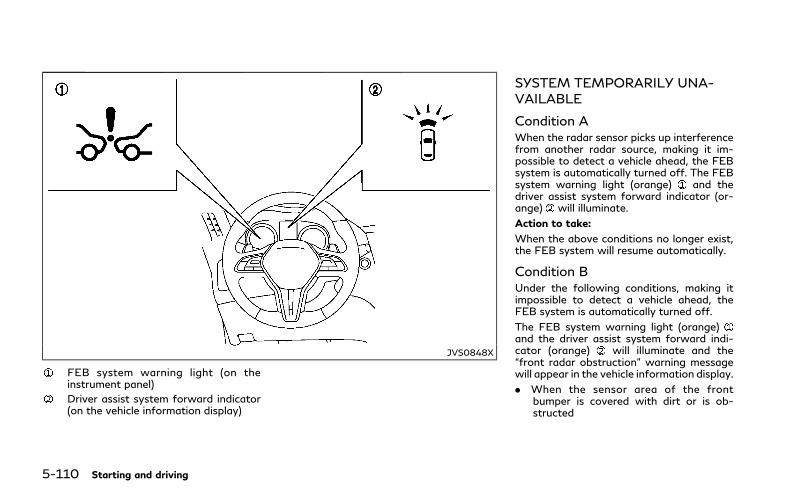
5-110 Starting and driving
JVS0848X
FEB system warning light (on theinstrument panel)
Driver assist system forward indicator(on the vehicle information display)
SYSTEM TEMPORARILY UNA-VAILABLE
Condition AWhen the radar sensor picks up interferencefrom another radar source, making it im-possible to detect a vehicle ahead, the FEBsystem is automatically turned off. The FEBsystem warning light (orange) and thedriver assist system forward indicator (or-ange) will illuminate.
Action to take:
When the above conditions no longer exist,the FEB system will resume automatically.
Condition BUnder the following conditions, making itimpossible to detect a vehicle ahead, theFEB system is automatically turned off.
The FEB system warning light (orange)and the driver assist system forward indi-cator (orange) will illuminate and the“front radar obstruction” warning messagewill appear in the vehicle information display.
. When the sensor area of the frontbumper is covered with dirt or is ob-structed
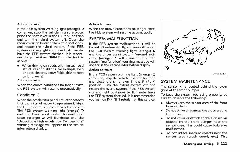
Action to take:
If the FEB system warning light (orange)comes on, stop the vehicle in a safe place,place the shift lever in the P (Park) positionand turn the hybrid system off. Clean theradar cover on lower grille with a soft cloth,and restart the hybrid system. If the FEBsystemwarning light continues to illuminate,have the FEB system checked. It is recom-mended you visit an INFINITI retailer for thisservice.
. When driving on roads with limited roadstructures or buildings (for example, longbridges, deserts, snow fields, driving nextto long walls)
Action to take:
When the above conditions no longer exist,the FEB system will resume automatically.
Condition CWhen the accelerator pedal actuator detectsthat the internal motor temperature is high,the FEB system is automatically turned off.The FEB system warning light (orange)and the driver assist system forward indi-cator (orange) will illuminate and the“Unavailable High Accelerator Temperature”warning message will appear in the vehicleinformation display.
Action to take:
When the above conditions no longer exist,the FEB system will resume automatically.
SYSTEM MALFUNCTIONIf the FEB system malfunctions, it will beturned off automatically, a chime will sound,the FEB system warning light (orange)and the driver assist system forward indi-cator (orange) will illuminate and thesystem “malfunction” warning message willappear in the vehicle information display.
Action to take:
If the FEB system warning light (orange)comes on, stop the vehicle in a safe locationand place the shift lever in the P (Park)position. Turn the hybrid system off andrestart the hybrid system. If the FEB systemwarning light continues to illuminate, havethe FEB system checked. It is recommendedyou visit an INFINITI retailer for this service.
JVS1123X
SYSTEM MAINTENANCEThe sensor is located behind the lowergrille of the front bumper.
To keep the system operating properly, besure to observe the following:
. Always keep the sensor area of the frontbumper clean.
. Do not strike or damage the areas aroundthe sensor.
. Do not cover or attach stickers or similarobjects on the front bumper near thesensor area. This could cause failure ormalfunction.
. Do not attach metallic objects near thesensor area (brush guard, etc.). This
Starting and driving 5-111
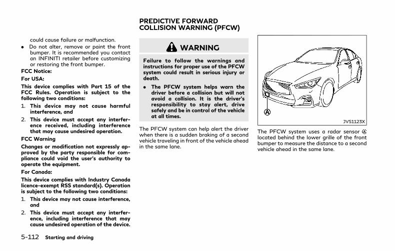
5-112 Starting and driving
could cause failure or malfunction.
. Do not alter, remove or paint the frontbumper. It is recommended you contactan INFINITI retailer before customizingor restoring the front bumper.
FCC Notice:
For USA:
This device complies with Part 15 of theFCC Rules. Operation is subject to thefollowing two conditions:
1. This device may not cause harmfulinterference, and
2. This device must accept any interfer-ence received, including interferencethat may cause undesired operation.
FCC Warning
Changes or modification not expressly ap-proved by the party responsible for com-pliance could void the user’s authority tooperate the equipment.
For Canada:
This device complies with Industry Canadalicence-exempt RSS standard(s). Operationis subject to the following two conditions:
1. This device may not cause interference,and
2. This device must accept any interfer-ence, including interference that maycause undesired operation of the device.
WARNING
Failure to follow the warnings andinstructions for proper use of the PFCWsystem could result in serious injury ordeath.
. The PFCW system helps warn thedriver before a collision but will notavoid a collision. It is the driver’sresponsibility to stay alert, drivesafely and be in control of the vehicleat all times.
The PFCW system can help alert the driverwhen there is a sudden braking of a secondvehicle traveling in front of the vehicle aheadin the same lane.
JVS1123X
The PFCW system uses a radar sensorlocated behind the lower grille of the frontbumper to measure the distance to a secondvehicle ahead in the same lane.
PREDICTIVE FORWARDCOLLISION WARNING (PFCW)

JVS0849X
Driver assist system forward indicator(on the vehicle information display)
Vehicle ahead detection indicator (onthe vehicle information display)
FEB system warning light (on theinstrument panel)
Lower display
Starting and driving 5-113

5-114 Starting and driving
JVS0294X
PFCW SYSTEM OPERATIONThe PFCW system operates at speeds aboveapproximately 3 MPH (5 km/h).
If there is a potential risk of a forwardcollision, the PFCW system will warn thedriver by blinking the driver assist systemforward indicator and the vehicle aheaddetection indicator, and sounding an audiblealert.

JVS0847X
FEB system warning light (on theinstrument panel)
Lower display
MENU button
TURNING THE PFCW SYSTEMON/OFFPerform the following steps to turn thePFCW system on or off.
1. Push the MENU button and touch[Driver Assistance] on the lower display.
2. Touch [Emergency Assist].
3. Touch [Forward emergency braking] toturn the system ON/OFF.
When the PFCW system is turned off, theFEB system warning light (orange) illumi-nates.
NOTE:
The PFCW system is integrated into theFEB system. There is not a separate selec-tion in the display for the PFCW system.When the FEB system is turned off, thePFCW system is also turned off.
Starting and driving 5-115

5-116 Starting and driving
JVS0295X
Illustration AJVS0296X
Illustration B
JVS0297X
Illustration C
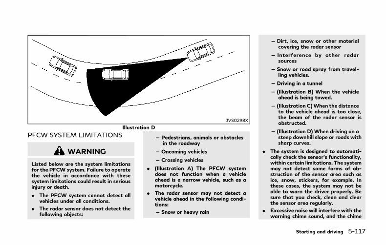
JVS0298X
Illustration D
PFCW SYSTEM LIMITATIONS
WARNING
Listed below are the system limitationsfor the PFCW system. Failure to operatethe vehicle in accordance with thesesystem limitations could result in seriousinjury or death.
. The PFCW system cannot detect allvehicles under all conditions.
. The radar sensor does not detect thefollowing objects:
— Pedestrians, animals or obstaclesin the roadway
— Oncoming vehicles
— Crossing vehicles
. (Illustration A) The PFCW systemdoes not function when a vehicleahead is a narrow vehicle, such as amotorcycle.
. The radar sensor may not detect avehicle ahead in the following condi-tions:
— Snow or heavy rain
— Dirt, ice, snow or other materialcovering the radar sensor
— Interference by other radarsources
— Snow or road spray from travel-ling vehicles.
— Driving in a tunnel
— (Illustration B) When the vehicleahead is being towed.
— (Illustration C)When the distanceto the vehicle ahead is too close,the beam of the radar sensor isobstructed.
— (Illustration D) When driving on asteep downhill slope or roads withsharp curves.
. The system is designed to automati-cally check the sensor’s functionality,within certain limitations. The systemmay not detect some forms of ob-struction of the sensor area such asice, snow, stickers, for example. Inthese cases, the system may not beable to warn the driver properly. Besure that you check, clean and clearthe sensor area regularly.
. Excessive noise will interfere with thewarning chime sound, and the chime
Starting and driving 5-117

5-118 Starting and driving
may not be heard.
SSD0253
When driving on some roads, such as wind-ing, hilly, curved, narrow roads, or roadswhich are under construction, the radarsensor may detect vehicles in a differentlane, or may temporarily not detect a vehicletraveling ahead. This may cause the PFCWsystem to work inappropriately.
The detection of vehicles may also beaffected by vehicle operation (steering man-euver or traveling position in the lane, etc.) orvehicle condition. If this occurs, the systemmay warn you by blinking the systemindicator and sounding the chime unexpect-edly. You will have to manually control theproper distance away from the vehicletraveling ahead.

JVS0848X
FEB system warning light (on theinstrument panel)
Driver assist system forward indicator(on the vehicle information display)
SYSTEM TEMPORARILY UNA-VAILABLE
Condition AWhen the radar sensor picks up interferencefrom another radar source, making it im-possible to detect a vehicle ahead, thePFCW system is automatically turned off.The FEB system warning light (orange)and the driver assist system forward indi-cator (orange) will illuminate.
Action to take:
When the above conditions no longer exist,the PFCW systemwill resume automatically.
Condition BUnder the following conditions, making itimpossible to detect a vehicle ahead, thePFCW system is automatically turned off.
The FEB system warning light (orange)and the driver assist system forward indi-cator (orange) will illuminate and the“front radar obstruction” warning messagewill appear in the vehicle information display.
. When the sensor area of the frontbumper is covered with dirt or is ob-structed
Starting and driving 5-119
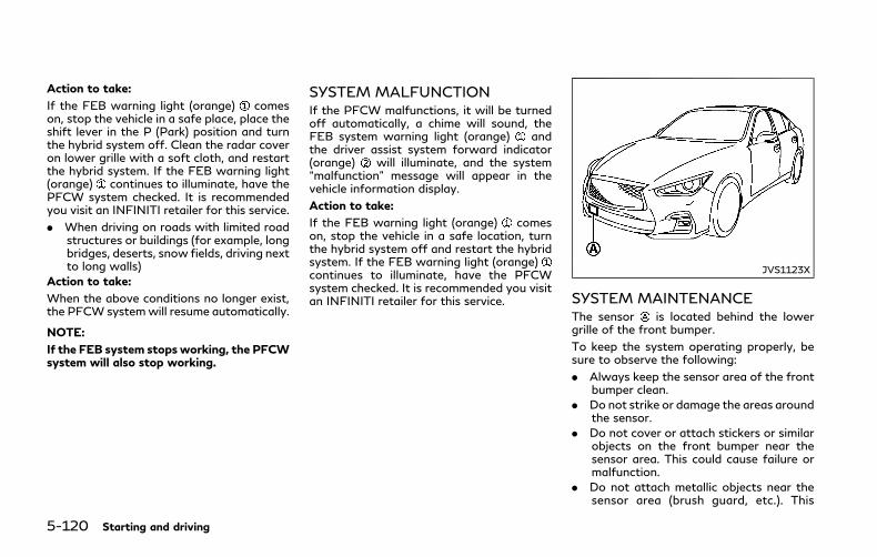
5-120 Starting and driving
Action to take:
If the FEB warning light (orange) comeson, stop the vehicle in a safe place, place theshift lever in the P (Park) position and turnthe hybrid system off. Clean the radar coveron lower grille with a soft cloth, and restartthe hybrid system. If the FEB warning light(orange) continues to illuminate, have thePFCW system checked. It is recommendedyou visit an INFINITI retailer for this service.
. When driving on roads with limited roadstructures or buildings (for example, longbridges, deserts, snow fields, driving nextto long walls)
Action to take:
When the above conditions no longer exist,the PFCW systemwill resume automatically.
NOTE:
If the FEB system stops working, the PFCWsystem will also stop working.
SYSTEM MALFUNCTIONIf the PFCW malfunctions, it will be turnedoff automatically, a chime will sound, theFEB system warning light (orange) andthe driver assist system forward indicator(orange) will illuminate, and the system“malfunction” message will appear in thevehicle information display.
Action to take:
If the FEB warning light (orange) comeson, stop the vehicle in a safe location, turnthe hybrid system off and restart the hybridsystem. If the FEB warning light (orange)continues to illuminate, have the PFCWsystem checked. It is recommended you visitan INFINITI retailer for this service.
JVS1123X
SYSTEM MAINTENANCEThe sensor is located behind the lowergrille of the front bumper.
To keep the system operating properly, besure to observe the following:
. Always keep the sensor area of the frontbumper clean.
. Do not strike or damage the areas aroundthe sensor.
. Do not cover or attach stickers or similarobjects on the front bumper near thesensor area. This could cause failure ormalfunction.
. Do not attach metallic objects near thesensor area (brush guard, etc.). This
could cause failure or malfunction.
. Do not alter, remove or paint the frontbumper. It is recommended you contactan INFINITI retailer before customizingor restoring the front bumper.
FCC Notice:
For USA:
This device complies with Part 15 of theFCC Rules. Operation is subject to thefollowing two conditions:
1. This device may not cause harmfulinterference, and
2. This device must accept any interfer-ence received, including interferencethat may cause undesired operation.
FCC Warning
Changes or modification not expressly ap-proved by the party responsible for com-pliance could void the user’s authority tooperate the equipment.
For Canada:
This device complies with Industry Canadalicence-exempt RSS standard(s). Operationis subject to the following two conditions:
1. This device may not cause interference,and
2. This device must accept any interfer-ence, including interference that maycause undesired operation of the device.
CAUTION
During the first 1,200 miles (2,000 km),follow these recommendations to obtainmaximum engine performance and en-sure the future reliability and economyof your new vehicle.
Failure to follow these recommendationsmay result in shortened engine life andreduced engine performance.
. Avoid driving for long periods at constantspeed, either fast or slow. Do not run theengine over 4,000 rpm.
. Do not accelerate at full throttle in anygear.
. Avoid quick starts.
. Avoid hard braking as much as possible.
Follow these easy-to-use Fuel EfficientDriving Tips to help you achieve the mostfuel economy from your vehicle.
1. Use smooth accelerator and brake pedalapplication.. Avoid rapid starts and stops.. Use smooth, gentle accelerator and
brake application whenever possible.. Maintain constant speed while com-
muting and coast whenever possible.
2. Maintain constant speed.. Look ahead to try and anticipate and
minimize stops.. Synchronizing your speed with traffic
lights allows you to reduce yournumber of stops.
. Maintaining a steady speed can mini-mize red light stops and improve fuelefficiency.
3. Use air conditioning (A/C) at highervehicle speeds.. Below 40 MPH (64 km/h), it is more
efficient to open windows to cool thevehicle due to reduced engine load.
. Above 40 MPH (64 km/h), it is moreefficient to use A/C to cool thevehicle due to increased aerodynamicdrag.
. Recirculating the cool air in the cabinwhen the A/C is on reduces coolingload.
Starting and driving 5-121
BREAK-IN SCHEDULE FUEL EFFICIENT DRIVING TIPS

5-122 Starting and driving
4. Drive at economical speeds and dis-tances.. Observing the speed limit and not
exceeding 60 MPH (97 km/h) (wherelegally allowed) can improve fuelefficiency due to reduced aerody-namic drag.
. Maintaining a safe following distancebehind other vehicles reduces unne-cessary braking.
. Safely monitoring traffic to anticipatechanges in speed permits reducedbraking and smooth accelerationchanges.
. Select a gear range suitable to roadconditions.
5. Use cruise control.. Using cruise control during highway
driving helps maintain a steady speed.. Cruise control is particularly effective
in providing fuel savings when drivingon flat terrains.
6. Plan for the shortest route.. Utilize a map or navigation system to
determine the best route to save time.
7. Avoid idling.. Shutting off your engine when safe
for stops exceeding 30-60 secondssaves fuel and reduces emissions.
8. Buy an automated pass for toll roads.. Automated passes permit drivers to
use special lanes to maintain cruisingspeed through the toll and avoidstopping and starting.
9. Winter warm up.. Limit idling time to minimize impact to
fuel economy.. Vehicles typically need no more than
30 seconds of idling at start-up toeffectively circulate the engine oilbefore driving.
. Your vehicle will reach its ideal oper-ating temperature more quickly whiledriving versus idling.
10.Keeping your vehicle cool.. Park your vehicle in a covered parking
area or in the shade whenever possi-ble.
. When entering a hot vehicle, openingthe windows will help to reduce theinside temperature faster, resulting inreduced demand on your A/C system.
. Keep your engine tuned up.
. Follow the recommended scheduledmaintenance.
. Keep the tires inflated to the correctpressure. Low tire pressure increases tirewear and lowers fuel economy.
. Keep the wheels in correct alignment.Improper alignment increases tire wearand lowers fuel economy.
. Use the recommended viscosity engineoil. (See “Engine oil and oil filter recom-mendation” (P.10-6).)
INCREASING FUEL ECONOMY

If any malfunction occurs in the IntelligentAll-Wheel Drive (AWD) system while theINFINITI Direct Response Hybrid® System isrunning, warning messages appear in thevehicle information display.
JVS0228M
If the “AWDError” warning appears, theremay be a malfunction in the Intelligent AWDsystem. Reduce vehicle speed and have thesystem checked as soon as possible. It isrecommended you visit an INFINITI retailerfor this service.
The “AWD High Temp.” (high temperature)warning may appear while trying to free a
stuck vehicle due to increased oil tempera-ture. The driving mode may change to Two-Wheel Drive (2WD). If this warning isdisplayed, stop the vehicle with the hybridsystem idling, as soon as it is safe to do so.Then if the warning turns off, you cancontinue driving.
The “Tire Size Incorrect” warning mayappear if there is a large difference betweenthe diameters of front and rear wheels. Pulloff the road in a safe area, with the hybridsystem idling. Check that all tire sizes are thesame, that the tire pressure is correct andthat the tires are not excessively worn.
If any warning message continues to bedisplayed, have your vehicle checked as soonas possible. It is recommended you visit anINFINITI retailer for this service.
WARNING
. For AWD equipped vehicles, do notattempt to raise two wheels off theground and shift the transmission toany drive or reverse position with thehybrid system running. Doing so mayresult in drivetrain damage or unex-pected vehicle movement which couldresult in serious vehicle damage orpersonal injury.
Starting and driving 5-123
INTELLIGENT ALL-WHEELDRIVE (AWD) (if so equipped)
5-124 Starting and driving
. Do not attempt to test an AWDequipped vehicle on a 2-wheel dy-namometer (such as the dynam-ometers used by some states foremissions testing) or similar equip-ment even if the other twowheels areraised off the ground. Make sure thatyou inform the test facility personnelthat your vehicle is equipped withAWD before it is placed on a dynam-ometer. Using the wrong test equip-ment may result in drivetrain damageor unexpected vehicle movementwhich could result in serious vehicledamage or personal injury.
CAUTION
. Do not operate the hybrid system ona free roller when any of the wheelsare raised.
. If the “AWD Error” warning appearswhile driving there may be a mal-function in the AWD system. Reducethe vehicle speed and have yourvehicle checked as soon as possible.It is recommended you visit anINFINITI retailer for this service.
. If the “AWD Error” warning remainson after the above operation, have
your vehicle checked as soon aspossible. It is recommended you visitan INFINITI retailer for this service.
. The power train may be damaged ifyou continue driving with the “AWDError” warning on.
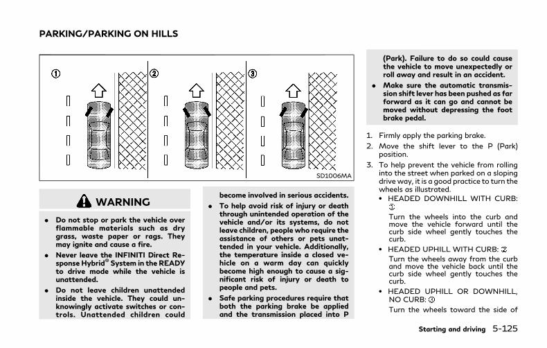
SD1006MA
WARNING
. Do not stop or park the vehicle overflammable materials such as drygrass, waste paper or rags. Theymay ignite and cause a fire.
. Never leave the INFINITI Direct Re-sponse Hybrid® System in the READYto drive mode while the vehicle isunattended.
. Do not leave children unattendedinside the vehicle. They could un-knowingly activate switches or con-trols. Unattended children could
become involved in serious accidents.
. To help avoid risk of injury or deaththrough unintended operation of thevehicle and/or its systems, do notleave children, people who require theassistance of others or pets unat-tended in your vehicle. Additionally,the temperature inside a closed ve-hicle on a warm day can quicklybecome high enough to cause a sig-nificant risk of injury or death topeople and pets.
. Safe parking procedures require thatboth the parking brake be appliedand the transmission placed into P
(Park). Failure to do so could causethe vehicle to move unexpectedly orroll away and result in an accident.
. Make sure the automatic transmis-sion shift lever has been pushed as farforward as it can go and cannot bemoved without depressing the footbrake pedal.
1. Firmly apply the parking brake.
2. Move the shift lever to the P (Park)position.
3. To help prevent the vehicle from rollinginto the street when parked on a slopingdrive way, it is a good practice to turn thewheels as illustrated.. HEADED DOWNHILL WITH CURB:
Turn the wheels into the curb andmove the vehicle forward until thecurb side wheel gently touches thecurb.
. HEADED UPHILL WITH CURB:
Turn the wheels away from the curband move the vehicle back until thecurb side wheel gently touches thecurb.
. HEADED UPHILL OR DOWNHILL,NO CURB:
Turn the wheels toward the side of
Starting and driving 5-125
PARKING/PARKING ON HILLS
5-126 Starting and driving
the road so the vehicle will move awayfrom the center of the road if itmoves.
4. Push the ignition switch to the OFFposition.
DIRECT ADAPTIVE STEERINGTYPE
WARNING
. When the power steering warninglight illuminates with the INFINITIDirect Response Hybrid® System run-ning, the power assist for the steer-ing will cease operation. You will stillhave control of the vehicle, but thesteering will be harder to operate.
. If wheels or tires other than theINFINITI recommended ones areused, Direct Adaptive Steering maynot operate properly and the powersteering warning light may illumi-nate.
. Do not modify the vehicle’s suspen-sion. If suspension parts such asshock absorbers, struts, springs, sta-bilizer bars, bushings and wheels arenot INFINITI recommended for yourvehicle or are extremely deteriorated,Direct Adaptive Steering may notoperate properly and the powersteering warning light may illumi-nate.
. Do not modify the vehicle’s steering.If steering parts are not INFINITI
recommended for your vehicle or areextremely deteriorated, Direct Adap-tive Steering may not operate prop-erly and the power steering warninglight may illuminate.
. If the VDC warning light illuminates,the power steering warning light mayalso illuminate at the same time. Stopthe vehicle in a safe location, turn thehybrid system off and restart thehybrid system. If the power steeringwarning light continues to illuminate,have the system checked. It is recom-mended you visit an INFINITI retailerfor this service. For the VDC system,see “Vehicle Dynamic Control (VDC)system” (P.5-130).
CAUTION
. Do not place the ignition switch is inthe ON position while the steeringwheel or a tire is removed.
. Do not turn the steering wheel asmuch as possible while the ignitionswitch is in any position other thanthe ON position.
. Installing an accessory on the steer-ing wheel, or changing the steering
POWER STEERING

wheel, may reduce the steering per-formance.
Direct Adaptive Steering is designed tocontrol the steering force and steering angleaccording to the vehicle speed and amountof turning of the steering wheel.
The steering characteristic can be selectedusing the INFINITI Drive Mode Selector. See“INFINITI Drive Mode Selector” (P.5-21).
If the VDC system is turned off, the settingof steering becomes Standard mode.
If the power steering warning light illumi-nates while the hybrid system is running, itmay indicate that Direct Adaptive Steering isnot functioning properly and may needservicing. It is recommended you have thesystem checked by an INFINITI retailer. (See“Power steering warning light” (P.2-14).)
When the power steering warning lightilluminates with the hybrid system running,the power assist for the steering will ceaseoperation. You will still have control of thevehicle. However, greater steering effort willbe needed, especially in sharp turns and atlow speeds.
If Direct Adaptive Steering is malfunction-ing, the steeringwheel may turn slightly evenwhen driving on a straight road.
Under the following conditions, the steering
wheel may turn slightly evenwhen driving ona straight road. This is due to a protectionmechanism for Direct Adaptive Steering. Thesteering wheel will return to the normalposition after the protection mechanism isdeactivated.
Condition A
. When the engine is stalled or likely to bestalled
. When the steering wheel is held in the fulllock position or when the front tiretouches an obstruction.
. When the battery is discharged
To return the steering wheel to the normalposition, stop the vehicle in a safe locationand stop operating the steering wheel. Thendrive the vehicle for a short period of time.
Condition B
. When the steering wheel is operatedrepeatedly or continuously while parkingor driving at a very low speed. In thiscase, the power assist for the steeringwheel will be reduced.
To return the steering wheel to the normalposition, stop the vehicle in a safe locationand wait for a period of time, withoutoperating the steering wheel, until thetemperature of Direct Adaptive Steeringcools down. Avoid repeated steering wheeloperations that could cause Direct AdaptiveSteering to overheat.
When the vehicle is tested on the 2-wheeldynamometer, the power steering warninglight may illuminate. To turn off the powersteering warning light, stop the vehicle in asafe location, turn the hybrid system off,restart the hybrid system, and then drive thevehicle for a period of time.
The following conditions do not indicate amalfunction of Direct Adaptive Steering.
. You may notice wider steering play whenthe ignition switch is in the OFF or ACCposition compared to when it is in theON position.
. After the hybrid system is started, thesteering wheel may turn slightly evenwhen driving on a straight road. Toreturn to the normal position, drive thevehicle on a straight road for a period oftime.
. After the hybrid system is started, thesteering wheel may move if the steeringwheel was turned to the fully lockedposition while the ignition switch was inthe OFF position.
. After the vehicle is tested on the 4-wheeldynamometer, the steering wheel mayturn slightly even when driving on astraight road. To return the steeringwheel to the normal position, drive thevehicle on a straight road for a period oftime.
Starting and driving 5-127

5-128 Starting and driving
You may hear a noise under the followingconditions. However, this is not a malfunc-tion.
. When the hybrid system is started orstopped.
. When the steering wheel is turned in thefull lock position.
BRAKING PRECAUTIONSThis vehicle is equipped with two brakingsystems.
. Hydraulic brake system
. Regenerative brake system
Hydraulic brake systemThe brake system has two separate hydrau-lic circuits. If one circuit malfunctions, youwill still have braking at two wheels.
Regenerative brake systemSee “Regenerative brake” (P.Hybrid System-8).
Using the brakesAvoid resting your foot on the brake pedalwhile driving. This will cause overheating ofthe brakes, wearing out the brake and padsfaster and reduce gas mileage.
To help save the brakes and to prevent thebrakes from overheating, reduce speed anddownshift to a lower gear before goingdown a slope or long grade. Overheatedbrakes may reduce braking performance andcould result in loss of vehicle control.
WARNING
. While driving on a slippery surface,be careful when braking, acceleratingor downshifting. Abrupt braking oraccelerating could cause the wheelsto skid and result in an accident.
. If the INFINITI Direct Response Hy-brid® System is not running or isturned off while driving, the powerassist for the brakes will be limited.Braking will be harder.
CAUTION
You may hear a operational noise whenthe brake pedal is depressed. This is not amalfunction.
Wet brakesWhen the vehicle is washed or driventhrough water, the brakes may get wet. Asa result, your braking distance will be longerand the vehicle may pull to one side duringbraking.
To dry brakes, drive the vehicle at a safespeed while lightly tapping the brake pedal
BRAKE SYSTEM
to heat-up the brakes. Do this until thebrakes return to normal. Avoid driving thevehicle at high speeds until the brakesfunction correctly.
PARKING BRAKE BREAK-INBreak in the parking brake shoes wheneverthe stopping effect of the parking brake isweakened or whenever the parking brakeshoes and/or drums/rotors are replaced, inorder to assure the best braking perfor-mance.
This procedure is described in the vehicleservice manual. It is recommended you visitan INFINITI retailer for this service.
BRAKE ASSISTWhen the force applied to the brake pedalexceeds a certain level, the Brake Assist isactivated generating greater braking forcethan a conventional brake booster even withlight pedal force.
WARNING
The Brake Assist is only an aid to assistbraking operation and is not a collisionwarning or avoidance device. It is thedriver’s responsibility to stay alert, drivesafely and be in control of the vehicle atall times.
ANTI-LOCK BRAKING SYSTEM(ABS)
WARNING
. The Anti-lock Braking System (ABS)is a sophisticated device, but itcannot prevent accidents resultingfrom careless or dangerous drivingtechniques. It can help maintain ve-hicle control during braking on slip-pery surfaces. Remember thatstopping distances on slippery sur-
faces will be longer than on normalsurfaces even with ABS. Stoppingdistances may also be longer onrough, gravel or snow covered roads,or if you are using tire chains. Alwaysmaintain a safe distance from thevehicle in front of you. Ultimately,the driver is responsible for safety.
. Tire type and condition may alsoaffect braking effectiveness.
— When replacing tires, install thespecified size of tires on all fourwheels.
— For detailed information, see“Wheels and tires” (P.8-28) ofthis manual.
The Anti-lock Braking System (ABS) controlsthe brakes so the wheels do not lock duringhard braking or when braking on slipperysurfaces. The system detects the rotationspeed at each wheel and varies the brakefluid pressure to prevent each wheel fromlocking and sliding. By preventing eachwheel from locking, the system helps thedriver maintain steering control and helps tominimize swerving and spinning on slipperysurfaces.
Starting and driving 5-129
BRAKE ASSIST

5-130 Starting and driving
Using the systemDepress the brake pedal and hold it down.Depress the brake pedal with firm steadypressure, but do not pump the brakes. TheABS will operate to prevent the wheels fromlocking up. Steer the vehicle to avoidobstacles.
WARNING
Do not pump the brake pedal. Doing somay result in increased stopping dis-tances.
Self-test featureThe ABS includes electronic sensors, electricpumps, hydraulic solenoids and a computer.The computer has a built-in diagnosticfeature that tests the system each time youstart the hybrid system and move the vehicleat a low speed in forward or reverse. Whenthe self-test occurs, you may hear a “clunk”noise and/or feel a pulsation in the brakepedal. This is normal and does not indicate amalfunction. If the computer senses a mal-function, it switches the ABS off andilluminates the ABS warning light on theinstrument panel. The brake system thenoperates normally, but without anti-lockassistance.
If the ABS warning light illuminates duringthe self-test or while driving, have thevehicle checked. It is recommended you visitan INFINITI retailer for this service.
Normal operationThe ABS operates at speeds above 3 to 6MPH (5 to 10 km/h).
When the ABS senses that one or morewheels are close to locking up, the actuatorrapidly applies and releases hydraulic pres-sure. This action is similar to pumping thebrakes very quickly. You may feel a pulsationin the brake pedal and hear a noise fromunder the hood or feel a vibration from theactuator when it is operating. This is normaland indicates that the ABS is operatingproperly. However, the pulsation may indi-cate that road conditions are hazardous andextra care is required while driving.
The Vehicle Dynamic Control (VDC) systemuses various sensors to monitor driver inputsand vehicle motion. Under certain drivingconditions, the VDC system helps to performthe following functions.
. Controls brake pressure to reduce wheelslip on one slipping drive wheel so poweris transferred to a non slipping drivewheel on the same axle.
. Controls brake pressure and engine ormotor output to reduce drive wheel slipbased on vehicle speed (traction controlfunction).
. Controls brake pressure at individualwheels and engine or motor output tohelp the driver maintain control of thevehicle in the following conditions:
— understeer (vehicle tends to not followthe steered path despite increasedsteering input)
— oversteer (vehicle tends to spin due tocertain road or driving conditions).
The VDC system can help the driver tomaintain control of the vehicle, but it cannotprevent loss of vehicle control in all drivingsituations.
When the VDC system operates, the VDCwarning light in the instrument panelflashes so note the following:
. The road may be slippery or the systemmay determine some action is required to
VEHICLE DYNAMIC CONTROL(VDC) SYSTEM

help keep the vehicle on the steered path.
. You may feel a pulsation in the brakepedal and hear a noise or vibration fromunder the hood. This is normal andindicates that the VDC system is workingproperly.
. Adjust your speed and driving to the roadconditions.
See “Vehicle Dynamic Control (VDC) warn-ing light” (P.2-15).
If a malfunction occurs in the system, theVDC warning light illuminates in theinstrument panel. The VDC system automa-tically turns off.
The VDC OFF switch is used to turn off theVDC system. The VDC off indicator lightilluminates to indicate the VDC system is off.When the VDC switch is used to turn off thesystem, the VDC system still operates toprevent one drive wheel from slipping bytransferring power to a non slipping drivewheel. The VDC warning light flashes ifthis occurs. All other VDC functions are off,except for rise-up and build-up, and brakeforce distribution, and the VDC warninglight will not flash. The VDC system isautomatically reset to on when the ignitionswitch is placed in the off position then backto the on position.
See “Vehicle Dynamic Control (VDC) warn-ing light” (P.2-15) and “Vehicle Dynamic
Control (VDC) off indicator light” (P.2-17).
The computer has a built-in diagnosticfeature that tests the system each time youstart the INFINITI Direct Response Hybrid®
System and move the vehicle forward or inreverse at a slow speed. When the self-testoccurs, you may hear a “clunk” noise and/orfeel a pulsation in the brake pedal. This isnormal and is not an indication of a mal-function.
RISE-UP AND BUILD-UPThe system gradually adjusts braking powerduring normal braking to help provide anenhanced brake feel.
BRAKE FORCE DISTRIBUTIONDuring braking while driving through turns,the system optimizes the distribution offorce to each of the four wheels dependingon the radius of the turn.
WARNING
. The VDC system is designed to helpthe driver maintain stability but doesnot prevent accidents due to abruptsteering operation at high speeds orby careless or dangerous drivingtechniques. Reduce vehicle speedand be especially careful when driving
and cornering on slippery surfacesand always drive carefully.
. The rise-up and build-up, and brakeforce distribution system may not beeffective depending on the drivingcondition. Always drive carefully andattentively.
. Do not modify the vehicle’s suspen-sion. If suspension parts such asshock absorbers, struts, springs, sta-bilizer bars, bushings and wheels arenot INFINITI recommended for yourvehicle or are extremely deteriorated,the VDC system may not operateproperly. This could adversely affectvehicle handling performance, andthe VDC warning light mayilluminate.
. If brake related parts such as brakepads, rotors and calipers are notINFINITI recommended or are extre-mely deteriorated, the VDC systemmay not operate properly and theVDC warning light may illumi-nate.
. If engine control related parts are notINFINITI recommended or are extre-mely deteriorated, the VDC warninglight may illuminate.
. When driving on extremely inclinedsurfaces such as higher banked cor-
Starting and driving 5-131

5-132 Starting and driving
ners, the VDC system may not oper-ate properly and the VDC warninglight may illuminate. Do not driveon these types of roads.
. When driving on an unstable surfacesuch as a turntable, ferry, elevator orramp, the VDCwarning light mayilluminate. This is not a malfunction.Restart the hybrid system after driv-ing onto a stable surface.
. If wheels or tires other than theINFINITI recommended ones areused, the VDC system may not oper-ate properly and the VDC warninglight may illuminate.
. The VDC system is not a substitutefor winter tires or tire chains on asnow covered road.
This system senses driving based on thedriver’s steering and acceleration/brakingpatterns, and controls brake pressure atindividual wheels to help smooth vehicleresponse.
When the SPORT mode is selected by theINFINITI Drive Mode Selector, the amountof brake control provided by the active tracecontrol is reduced.
When the PERSONAL mode is selected, theactive trace control can be set to ON(enabled) or OFF (disabled). See “INFINITIDrive Mode Selector” (P.5-21).
When the VDC OFF switch is used to turnoff the VDC system, the active trace controlis also turned off.
ACTIVE TRACE CONTROL
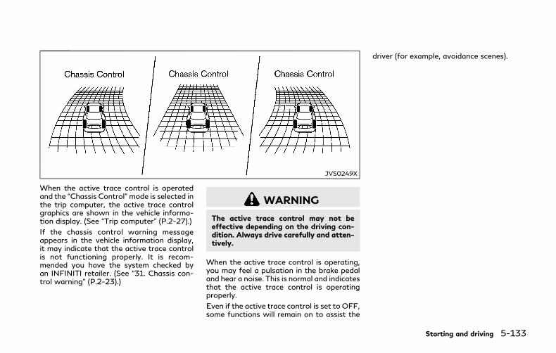
JVS0249X
When the active trace control is operatedand the “Chassis Control” mode is selected inthe trip computer, the active trace controlgraphics are shown in the vehicle informa-tion display. (See “Trip computer” (P.2-27).)
If the chassis control warning messageappears in the vehicle information display,it may indicate that the active trace controlis not functioning properly. It is recom-mended you have the system checked byan INFINITI retailer. (See “31. Chassis con-trol warning” (P.2-23).)
WARNING
The active trace control may not beeffective depending on the driving con-dition. Always drive carefully and atten-tively.
When the active trace control is operating,you may feel a pulsation in the brake pedaland hear a noise. This is normal and indicatesthat the active trace control is operatingproperly.
Even if the active trace control is set to OFF,some functions will remain on to assist the
driver (for example, avoidance scenes).
Starting and driving 5-133
5-134 Starting and driving
WARNING
. Never rely solely on the hill startassist system to prevent the vehiclefrom moving backward on a hill.Always drive carefully and atten-tively. Depress the brake pedal whenthe vehicle is stopped on a steep hill.Be especially careful when stoppedon a hill on frozen or muddy roads.Failure to prevent the vehicle fromrolling backwards may result in a lossof control of the vehicle and possibleserious injury or death.
. The hill start assist system is notdesigned to hold the vehicle at astandstill on a hill. Depress the brakepedal when the vehicle is stopped ona steep hill. Failure to do so maycause the vehicle to roll backwardsand may result in a collision or seriouspersonal injury.
. The hill start assist system may notprevent the vehicle from rolling back-wards on a hill under all load or roadconditions. Always be prepared todepress the brake pedal to preventthe vehicle from rolling backwards.Failure to do so may result in acollision or serious personal injury.
The hill start assist system automaticallykeeps the brakes applied to help prevent thevehicle from rolling backwards in the time ittakes the driver to release the brake pedaland apply the accelerator when the vehicle isstopped on a hill.
The hill start assist system will operateautomatically under the following condi-tions:
. The transmission is shifted to a forwardor reverse gear.
. The vehicle is stopped completely on a hillby applying the brake.
The maximum holding time is 2 seconds.After 2 seconds the vehicle will begin to rollback and the hill start assist system will stopoperating completely.
The hill start assist system will not operatewhen the transmission is shifted to the N(Neutral) or P (Park) position or on a flat andlevel road.
The chassis control is an electric controlmodule that includes the following func-tions:
. Log-in function (See “Log-in function”(P.3-15).)
. INFINITI Drive Mode Selector (See“INFINITI Drive Mode Selector” (P.5-21).)
. Active Lane Control (if so equipped) (See“Active Lane Control” (P.5-24).)
. Active Trace Control (See “Active tracecontrol” (P.5-132).)
HILL START ASSIST SYSTEM CHASSIS CONTROL

FREEING A FROZEN DOOR LOCKTo prevent a door lock from freezing, applydeicer through the key hole. If the lockbecomes frozen, heat the key before insert-ing it into the key hole or use the IntelligentKey system.
ANTIFREEZEIn the winter when it is anticipated that theoutside temperature will drop below 32°F(0°C), check antifreeze to assure properwinter protection. For additional informa-tion, see “Engine cooling system” (P.8-5) and“Inverter cooling system” (P.8-7).
12-VOLT BATTERYIf the 12-volt battery is not fully chargedduring extremely cold weather conditions,the battery fluid may freeze and damage the12-volt battery. To maintain maximum effi-ciency, the 12-volt battery should bechecked regularly. For additional informa-tion, see “12-volt battery” (P.8-14).
DRAINING OF COOLANT WATERIf the vehicle is to be left outside withoutantifreeze, drain the cooling system, includ-ing the engine block. Refill before operatingthe vehicle. For details, see “Engine coolingsystem” (P.8-5) and “Inverter cooling sys-tem” (P.8-7).
TIRE EQUIPMENTSUMMER tires have a tread designed toprovide superior performance on dry pave-ment. However, the performance of thesetires will be substantially reduced in snowyand icy conditions. If you operate yourvehicle on snowy or icy roads, INFINITIrecommends the use of MUD & SNOW orALL SEASON tires on all four wheels. It isrecommended you consult an INFINITI re-tailer for the tire type, size, speed rating andavailability information.
For additional traction on icy roads, studdedtires may be used. However, some U.S.states and Canadian provinces prohibit theiruse. Check local, state and provincial lawsbefore installing studded tires.
Skid and traction capabilities of studdedsnow tires, on wet or dry surfaces, may bepoorer than that of non-studded snow tires.
Tire chains may be used. For details, see“Tire chains” (P.8-35) of this manual.
Intelligent All-Wheel Drive (AWD)modelsIf you install snow tires, they must also bethe same size, brand, construction and treadpattern on all four wheels.
SPECIAL WINTER EQUIPMENTIt is recommended that the following itemsbe carried in the vehicle during winter:
. A scraper and stiff-bristled brush toremove ice and snow from the windowsand wiper blades.
. A sturdy, flat board to be placed underthe jack to give it firm support.
. A shovel to dig the vehicle out ofsnowdrifts.
. Extra window washer fluid to refill thereservoir tank.
DRIVING ON SNOW OR ICE
WARNING
. Wet ice (32°F, 0°C and freezing rain),very cold snow or ice can be slick andvery hard to drive on. The vehicle willhave much less traction or “grip”under these conditions. Try to avoiddriving on wet ice until the road issalted or sanded.
. Whatever the condition, drive withcaution. Accelerate and slow downwith care. If accelerating or down-shifting too fast, the drive wheels willlose even more traction.
Starting and driving 5-135
COLD WEATHER DRIVING

5-136 Starting and driving
. Allow more stopping distance underthese conditions. Braking should bestarted sooner than on dry pave-ment.
. Allow greater following distances onslippery roads.
. Watch for slippery spots (glare ice).These may appear on an otherwiseclear road in shaded areas. If a patchof ice is seen ahead, brake beforereaching it. Try not to brake while onthe ice, and avoid any sudden steer-ing maneuvers.
. Do not use the cruise control onslippery roads.
. Snow can trap dangerous exhaustgases under your vehicle. Keep snowclear of the exhaust pipe and fromaround your vehicle.
ENGINE BLOCK HEATER (if soequipped)Engine block heaters are used to assist incold temperature starting.
The engine block heater should be usedwhen the outside temperature is 20°F(−7°C) or lower.
To use the engine block heater1. Turn the INFINITI Direct Response Hy-
brid® System off.
2. Open the hood and unwrap the engineblock heater cord.
3. Plug the engine block heater cord into agrounded 3-wire, 3-pronged extensioncord.
4. Plug the extension cord into a GroundFault Interrupt (GFI) protected,grounded 110-volt AC (VAC) outlet.
5. The engine block heater must be pluggedin for at least 2 - 4 hours, depending onoutside temperatures, to properly warmthe engine coolant. Use an appropriatetimer to turn the engine block heater on.
6. Before starting the hybrid system, un-plug and properly store the cord to keepit away from moving parts.
WARNING
. Do not use your engine block heaterwith an ungrounded electrical systemor a 2-pronged adapter. You can beseriously injured by an electricalshock if you use an ungroundedconnection.
. Disconnect and properly store theengine block heater cord beforestarting the hybrid system. Damageto the cord could result in an elec-trical shock and can cause seriousinjury.
. Use a heavy-duty 3-wire, 3-prongedextension cord rated for at least 10A.Plug the extension cord into a GroundFault Interrupt (GFI) protected,grounded 110-VAC outlet. Failureto use the proper extension cord ora grounded outlet can result in a fireor electrical shock and cause seriouspersonal injury.
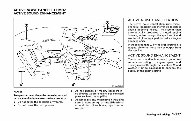
JVS0263X
NOTE:
To operate the active noise cancellation andactive sound enhancement system properly:
. Do not cover the speakers or woofer.
. Do not cover the microphones.
. Do not change or modify speakers in-cluding the woofer and any audio relatedparts such as the amplifier.
. Do not make any modification includingsound deadening or modificationsaround the microphones, speakers orwoofer.
ACTIVE NOISE CANCELLATIONThe active noise cancellation uses micro-phones located inside the vehicle to detectengine booming noises. The system thenautomatically produces a muted enginebooming noise through the speakers andwoofer (if so equipped) to reduce enginebooming noise.
If the microphone or the area around it istapped, abnormal noise may be output fromthe speaker.
ACTIVE SOUND ENHANCEMENTThe active sound enhancement generatessounds according to engine speed anddriving modes through the speakers andwoofer (if so equipped) to enhance thequality of the engine sound.
Starting and driving 5-137
ACTIVE NOISE CANCELLATION/ACTIVE SOUND ENHANCEMENT

5-138 Starting and driving
MEMO
6 In case of emergency
Hazard warning flasher switch ..................................... 6-2
Roadside assistance program ........................................ 6-2
Emergency INFINITI Direct Response Hybrid®
System shut off ................................................................. 6-3
Flat tire ................................................................................. 6-3
Tire Pressure Monitoring System (TPMS)............ 6-3
Run-flat tires ................................................................. 6-4
If the vehicle does not start .......................................... 6-5
Confirm battery is discharged................................ 6-5
Jump starting ..................................................................... 6-5
Push starting ....................................................................... 6-7
If your vehicle overheats ................................................ 6-8
Towing your vehicle ......................................................... 6-9
Towing recommended by INFINITI .................... 6-10
Vehicle recovery (freeing a stuck vehicle) ......... 6-11

6-2 In case of emergency
SIC2574
Push the switch on to warn other driverswhen you must stop or park under emer-gency conditions. All turn signal lights willflash.
WARNING
. If stopping for an emergency, be sureto move the vehicle well off the road.
. Do not use the hazard warningflashers while moving on the highwayunless unusual circumstances forceyou to drive so slowly that yourvehicle might become a hazard toother traffic.
. Turn signals do not work when thehazard warning flasher lights are on.
The flasher can be actuated with the ignitionswitch in any position.
When an impact that could activate thesupplemental air bags is detected, thehazard warning flasher lights blink automa-tically. If the hazardwarning flasher switch ispushed, the hazardwarning flashers will turnoff.
WARNING
Do not turn the hazard warning flasherswitch to off until you can make surethat it is safe to do so. Also, the hazardflasher warning may not blink automa-tically depending on the force of impact.
Some state laws may prohibit the use of thehazardwarning flasher switchwhile driving.
In the event of a roadside emergency,Roadside Assistance Service is available toyou. Please refer to your Warranty Informa-tion Booklet (U.S.) or Warranty & RoadsideAssistance Information Booklet (Canada) fordetails.
HAZARDWARNING FLASHER SWITCH ROADSIDE ASSISTANCE PROGRAM
To shut off the INFINITI Direct ResponseHybrid® System in an emergency situationwhile driving, perform the following proce-dure:
. Rapidly push the push-button ignitionswitch 3 consecutive times in less than1.5 seconds, or
. Push and hold the push-button ignitionswitch for more than 2 seconds.
Your vehicle is equipped with run-flat tiresand you can continue driving to a safelocation even if they are punctured. (See“Run-flat tires” (P.8-34).)
TIRE PRESSURE MONITORINGSYSTEM (TPMS)This vehicle is equipped with the TirePressure Monitoring System (TPMS). Itmonitors tire pressure of all tires except thespare. When the low tire pressure warninglight is lit and the “Tire Pressure Low - AddAir” warning appears in the vehicle informa-tion display, one or more of your tires issignificantly under-inflated. If the vehicle isbeing driven with low tire pressure, theTPMS will activate and warn you of it bythe low tire pressure warning light. Thissystem will activate only when the vehicle isdriven at speeds above 16 MPH (25 km/h).For more details, see “Low tire pressurewarning light” (P.2-12) and “Tire PressureMonitoring System (TPMS)” (P.5-5).
WARNING
. Radio waves could adversely affectelectric medical equipment. Thosewho use a pacemaker should contactthe electric medical equipment man-ufacturer for the possible influences
before use.
. If the low tire pressure warning lightilluminates while driving, avoid sud-den steering maneuvers or abruptbraking, reduce vehicle speed, pulloff the road to a safe location andstop the vehicle as soon as possible.Driving with under-inflated tires maypermanently damage the tires andincrease the likelihood of tire failure.Serious vehicle damage could occurand may lead to an accident andcould result in serious personal injury.Check the tire pressure for all fourtires. Adjust the tire pressure to therecommended COLD tire pressureshown on the Tire and LoadingInformation label to turn the low tirepressure warning light OFF. If thelight still illuminates while drivingafter adjusting the tire pressure, atire may be flat.
. When a wheel is replaced, the TPMSwill not function and the low tirepressure warning light will flash forapproximately 1 minute. The light willremain on after 1 minute. Have yourtires replaced and/or TPMS systemreset as soon as possible. It is recom-mended you visit an INFINITI retailerfor these services.
In case of emergency 6-3
EMERGENCY INFINITI DIRECTRESPONSEHYBRID® SYSTEMSHUTOFF FLAT TIRE
6-4 In case of emergency
. Replacing tires with those not origin-ally specified by INFINITI could affectthe proper operation of the TPMS.
. Do not inject any tire liquid or aerosoltire sealant into the tires, as this maycause a malfunction of the tire pres-sure sensors.
RUN-FLAT TIRESRun-flat tires are those tires that can beused temporarily if they are punctured. See“Run-flat tires” (P.8-34).
Also, refer to “Important Tire Safety Infor-mation” (US) or “Tire Safety Information”(Canada) in the INFINITI Warranty Informa-tion Booklet.
WARNING
. Although you can continue drivingwith a punctured run-flat tire, re-member that vehicle handling stabi-lity is reduced, which could lead to anaccident and personal injury. Also,driving a long distance at high speedsmay damage the tires.
. Do not drive at speeds above 50MPH (80 km/h) and do not drivemore than approximately 93 miles
(150 km) with a punctured run-flattire. The actual distance the vehiclecan be driven on a flat tire depends onoutside temperature, vehicle load,road conditions and other factors.
. Drive safely at reduced speeds. Avoidhard cornering or braking, which maycause you to lose control of thevehicle.
. If you detect any unusual sounds orvibrations while driving with a punc-tured run-flat tire, pull off the roadto a safe location and stop the vehicleas soon as possible. The tire may beseriously damaged and need to bereplaced.
CAUTION
. Never install tire chains on a punctu-red run-flat tire, as this could damageyour vehicle.
. Avoid driving over any projection orpothole, as the clearance betweenthe vehicle and the ground is smallerthan normal.
. Do not enter an automated car washwith a punctured run-flat tire.
. It is recommended you have thepunctured tire inspected by anINFINITI retailer or other authorizedrepair shop. Replace the tire as soonas possible if the tire is seriouslydamaged.
If you have a flat tire and have to stop thevehicle, follow the instructions below.
1. Safely move the vehicle off the road andaway from traffic.
2. Turn on the hazard warning flashers.
3. Park on a level surface and apply theparking brake.Move the shift lever to theP (Park) position.
4. Turn off the hybrid system.
5. Raise the hood to warn other traffic, andto signal professional road assistancepersonnel that you need assistance.
6. Have all passengers get out of thevehicle and stand in a safe place, awayfrom traffic and clear of the vehicle.
For the tire removing procedure, see “Jack-ing up the vehicle and replacing tires” (P.8-39).
Before attempting to jump start the vehicle,make sure the fuel tank is not empty and thecorrect starting procedure is followed. See“Starting the INFINITI Direct ResponseHybrid® System” (P.5-14). Do not drive thevehicle on battery power only if the fuel tankis empty. The Lithium ion (Li-ion) battery willbecome discharged and the INFINITI DirectResponse Hybrid® System will turn off.
CONFIRM BATTERY IS DIS-CHARGEDIf any of the following conditions occurs, the12-volt battery might discharged:
. The instrument cluster and/or headlightsare not normal brightness.
. Audio accessories cannot be turned on.
. The hybrid system does not becomeREADY to drive mode.
. The ignition switch cannot be placed inthe ON position.
Check the following if you notice aboveconditions.
1. Check that the 12-volt battery terminalsare tight and clean. See “12-volt battery”(P.8-14). The 12-volt battery is locatedon the left hand side of the trunk behindan access panel. If the 12-volt batteryterminals are loose, it is recommendedyou contact an INFINITI retailer.
2. If the 12-volt battery terminals are tightand clean, try to jump start the vehicle.See “Jump starting” (P.6-5).
If the hybrid system still does not start, it isrecommended that you contact an INFINITIretailer.
To start your INFINITI Direct ResponseHybrid® System with a booster battery, theinstructions and precautions below must befollowed.
Jump starting provides power to the 12 voltsystem to allow the electrical systems tooperate. The electrical systems must beoperating to allow the Lithium ion (Li-ion)battery to be charged. Jump starting doesnot charge the Li-ion battery.
WARNING
. If done incorrectly, jump starting canlead to a 12-volt battery explosion,resulting in severe injury or death. Itcould also damage your vehicle.
. Explosive hydrogen gas is alwayspresent in the vicinity of the 12-voltbattery. Make sure that the venttube is mounted.
. Do not allow battery fluid to comeinto contact with eyes, skin, clothingor painted surfaces. Battery fluid is acorrosive sulfuric acid solution whichcan cause severe burns. If the fluidshould come into contact with any-thing, immediately flush the con-tacted area with water.
. Keep the 12-volt battery out of thereach of children.
In case of emergency 6-5
IF THE VEHICLE DOES NOT START JUMP STARTING

6-6 In case of emergency
. The booster battery must be rated at12 volts. Use of an improperly ratedbattery can damage your vehicle.
. Whenever working on or near a 12-volt battery, always wear suitableeye protectors (for example, gogglesor industrial safety spectacles) andremove rings, metal bands, or anyother jewelry. Do not lean over the12-volt battery when jump starting.
. Do not attempt to jump start afrozen battery. It could explode andcause serious injury.
. Your vehicle has an automatic enginecooling fan. It could come on at anytime. Keep hands and other objectsaway from it.
CAUTION
Do not attempt to jump start a hybridvehicle as a booster vehicle.
JVE0174X
WARNING
Always follow the instructions below.Failure to do so could result in damage tothe charging system and cause personalinjury.
1. If the booster battery is in anothervehicle , position the two vehicles (and ) to bring the battery and the fusebox into close proximity to each other.
Do not allow the two vehicles to touch.
2. Apply parking brake. Move the shift leverto the P (Park) position. Switch off all

unnecessary electrical systems (light,heater, air conditioner, etc.).
3. Connect jumper cables in the sequenceas illustrated ( ? ? ? ).
CAUTION
. Always connect positive (+) to posi-tive (+) and negative (−) to bodyground (as illustrated) − not to the12-volt battery.
. Make sure the jumper cables do nottouch moving parts in the enginecompartment and that clamps donot contact any other metal.
4. Start the engine of the booster vehicleand let it run for a few minutes.
5. Start the hybrid system of the vehiclebeing jump started .
CAUTION
If the hybrid system does not start rightaway, push the ignition switch to theOFF position and wait 10 secondsbefore trying again.
6. After starting your hybrid system, care-fully disconnect the negative cable andthen the positive cable ( ? ? ?).
NOTE:
If it is not possible to turn the hybrid systemON by following this procedure, it isrecommended that you contact an INFINITIretailer immediately.
Do not attempt to start the engine bypushing.
CAUTION
. Automatic Transmission (AT) modelscannot be push-started or tow-started. Attempting to do so maycause transmission damage.
. Three-way catalyst equipped modelsshould not be started by pushingsince the three-way catalyst may bedamaged.
. Never try to start the vehicle bytowing it; when the engine starts,the forward surge could cause thevehicle to collide with the tow vehi-cle.
. Hybrid models cannot be push-started or tow-started. Attemptingto do so may cause electrical ortransmission damage.
In case of emergency 6-7
PUSH STARTING
6-8 In case of emergency
CAUTION
. Do not continue to drive if yourvehicle overheats. Doing so couldcause engine damage or a vehicle fire.
. To avoid the danger of being scalded,never remove the radiator cap whilethe engine is still hot. When theradiator cap is removed, pressurizedhot water will spurt out, possiblycausing serious injury.
. Do not open the hood if steam iscoming out.
If your vehicle is overheating (indicated by anextremely high temperature gauge reading),or if you feel a lack of engine power, detectabnormal noise, etc., take the followingsteps:
1. Move the vehicle safely off the road,apply the parking brake and move theshift lever to the P (Park) position.
Do not turn the INFINITI Direct Re-sponse Hybrid® System off.
2. Turn off the climate control. Open all thewindows, move the heater or air condi-tioner temperature control to maximumhot and fan control to high speed.
3. If engine overheating is caused by climb-ing a long hill on a hot day, run the engineat a fast idle (approximately 1,500 rpm)until the temperature gauge indicationreturns to normal.
4. Get out of the vehicle. Look and listen forsteam or coolant escaping from theradiator before opening the hood. (Ifsteam or coolant is escaping, turn off thehybrid system.) Do not open the hoodfurther until no steam or coolant can beseen.
5. Open the engine hood.
WARNING
If steam or water is coming from theengine, stand clear to prevent gettingburned.
6. Also check if the cooling fan is running.The radiator hoses and radiator shouldnot leak water. If coolant is leaking or thecooling fan does not run, stop the hybridsystem.
WARNING
Be careful not to allow your hands, hair,jewelry or clothing to come into contactwith, or get caught in, the engine coolingfan. The engine cooling fan can start atany time.
7. After the engine cools down, check thecoolant level in the reservoir tank withthe engine running. Add coolant to thereservoir tank if necessary. Have yourvehicle repaired. It is recommended youvisit an INFINITI retailer for this service.
IF YOUR VEHICLE OVERHEATS

When towing your vehicle, all State (Pro-vincial in Canada) and local regulations fortowing must be followed. Incorrect towingequipment could damage your vehicle. Tow-ing instructions are available from anINFINITI retailer. Local service operatorsare familiar with the applicable laws andprocedures for towing. To assure propertowing and to prevent accidental damage toyour vehicle, INFINITI recommends that youhave a service operator tow your vehicle. It isadvisable to have the service operator care-fully read the following precautions.
WARNING
. Never ride in a vehicle that is beingtowed.
. Never get under your vehicle after ithas been lifted by a tow truck.
CAUTION
. When towing, make sure that thetransmission, axles, steering systemand powertrain are in working con-dition. If any unit is damaged, dolliesmust be used.
. Always attach safety chains before
towing.
For information about towing your vehiclebehind a recreational vehicle (RV), see “Flattowing” (P.10-18).
In case of emergency 6-9
TOWING YOUR VEHICLE

6-10 In case of emergency
SCE0788
Two-Wheel Drive (2WD) models
TOWING RECOMMENDED BYINFINITI
Two-Wheel Drive (2WD) modelsINFINITI recommends that your vehicle betowed with the driving (rear) wheels off theground or place the vehicle on a flat bedtruck as illustrated. The vehicle should onlybe loaded onto a flat bed using a winch.
WARNING
If your vehicle needs to be towed, do itwith the rear wheels raised. If the rear
wheels are on the ground when towing,the electric motor may generate electri-city. This may damage the INFINITIDirect Response Hybrid® System com-ponents and cause a fire.
CAUTION
. Never tow automatic transmissionmodels with the rear wheels on theground or four wheels on the ground(forward or backward), as this maycause serious and expensive damage
to the transmission. If it is necessaryto tow the vehicle with the frontwheels raised, always use towingdollies under the rear wheels.
. When towing rear wheel drive modelswith the front wheels on the groundor on towing dollies: Push the ignitionswitch to the ACC or ON position,and secure the steering wheel in astraight-ahead position with a ropeor similar device.
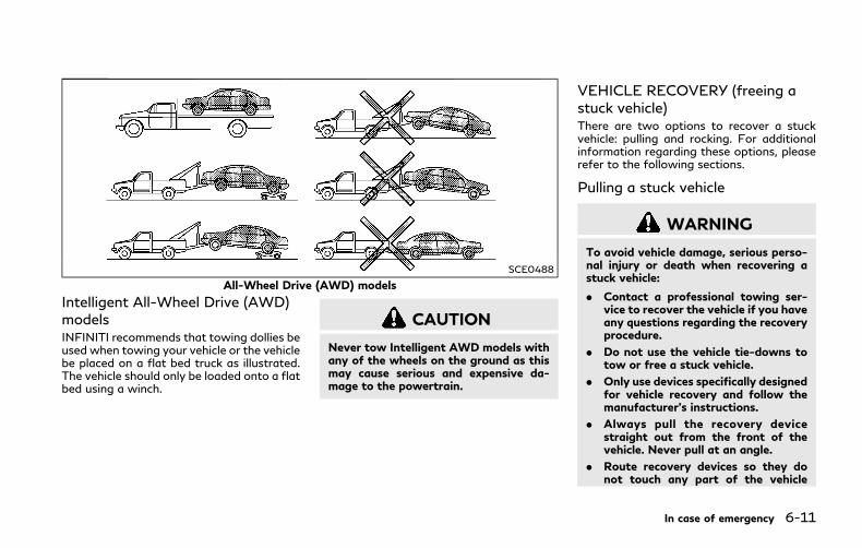
SCE0488
All-Wheel Drive (AWD) models
Intelligent All-Wheel Drive (AWD)modelsINFINITI recommends that towing dollies beused when towing your vehicle or the vehiclebe placed on a flat bed truck as illustrated.The vehicle should only be loaded onto a flatbed using a winch.
CAUTION
Never tow Intelligent AWD models withany of the wheels on the ground as thismay cause serious and expensive da-mage to the powertrain.
VEHICLE RECOVERY (freeing astuck vehicle)There are two options to recover a stuckvehicle: pulling and rocking. For additionalinformation regarding these options, pleaserefer to the following sections.
Pulling a stuck vehicle
WARNING
To avoid vehicle damage, serious perso-nal injury or death when recovering astuck vehicle:
. Contact a professional towing ser-vice to recover the vehicle if you haveany questions regarding the recoveryprocedure.
. Do not use the vehicle tie-downs totow or free a stuck vehicle.
. Only use devices specifically designedfor vehicle recovery and follow themanufacturer’s instructions.
. Always pull the recovery devicestraight out from the front of thevehicle. Never pull at an angle.
. Route recovery devices so they donot touch any part of the vehicle
In case of emergency 6-11
6-12 In case of emergency
except the attachment point.
If your vehicle is stuck in sand, snow, mud,etc., use a tow strap or other devicedesigned specifically for vehicle recovery.Always follow the manufacturer’s instruc-tions for the recovery device.
NOTE:
Do not use the tie-down hooks for towingor vehicle recovery.
Rocking a stuck vehicleIf your vehicle is stuck in sand, snow, mud,etc., use the following procedure:
1. Turn off the Vehicle Dynamic Control(VDC) system.
2. Make sure the area in front and behindthe vehicle is clear of obstructions.
3. Turn the steering wheel right and left toclear an area around the front tires.
4. Slowly rock the vehicle forward andbackward.. Shift back and forth between R (Re-
verse) and D (Drive).. Apply the accelerator as little as
possible to maintain the rocking mo-tion.
. Release the accelerator pedal beforeshifting between R and D.
. Do not spin the tires above 35 MPH(55 km/h).
5. If the vehicle cannot be freed after a fewtries, contact a professional towingservice to remove the vehicle.
WARNING
. Stand clear of a stuck vehicle.
. Do not spin your tires at high speed.This could cause them to explode andresult in serious injury. Parts of yourvehicle could also overheat and bedamaged.

7 Appearance and care
Cleaning exterior ................................................................ 7-2
Washing........................................................................... 7-2
Waxing ............................................................................. 7-2
Removing spots ............................................................. 7-3
Underbody ...................................................................... 7-3
Glass ................................................................................. 7-3
Wheels ............................................................................. 7-3
Chrome parts ................................................................ 7-4
Tire dressing .................................................................. 7-4
Cleaning interior ................................................................. 7-5
Lithium-ion (Li-ion) battery and DC/DCconverter air vent ....................................................... 7-5
Air fresheners............................................................... 7-6
Floor mats..................................................................... 7-6
Seat belts ...................................................................... 7-7
Corrosion protection........................................................ 7-8
Most common factors contributing tovehicle corrosion ........................................................ 7-8
Environmental factors influence the rateof corrosion ................................................................. 7-8
To protect your vehicle from corrosion............... 7-8
7-2 Appearance and care
In order to maintain the appearance of yourvehicle, it is important to take proper care ofit.
To protect the paint surface, wash yourvehicle as soon as you can:
. after a rainfall to prevent possible da-mage from acid rain
. after driving on coastal roads
. when contaminants such as soot, birddroppings, tree sap, metal particles orbugs get on the paint surface
. when dust or mud builds up on thesurface
Whenever possible, store or park yourvehicle inside a garage or in a covered area.
When it is necessary to park outside, park ina shady area or protect the vehicle with abody cover.
Be careful not to scratch the paint surfacewhen putting on or removing the bodycover.
WASHINGWash dirt off the vehicle with a wet spongeand plenty of water. Clean the vehiclethoroughly using a mild soap, a specialvehicle soap or general purpose dishwashingliquid mixedwith clean, lukewarm (never hot)water.
CAUTION
. Do not use car washes that use acid inthe detergent. Some car washes,especially brushless ones, use someacid for cleaning. The acid may reactwith some plastic vehicle compo-nents, causing them to crack. Thiscould affect their appearance, andalso could cause them not to functionproperly. Always check with your carwash to confirm that acid is not used.
. Do not wash the vehicle with stronghousehold soap, strong chemical de-tergents, gasoline or solvents.
. Do not wash the vehicle in directsunlight or while the vehicle body ishot, as the surface may becomewater-spotted.
. Avoid using tight-napped or roughcloths, such as washing mitts. Caremust be taken when removing caked-
on dirt or other foreign substances sothe paint surface is not scratched ordamaged.
Rinse the vehicle again with plenty of cleanwater.
Inside flanges, seams and folds on the doors,hatches and hood are particularly vulnerableto the effects of road salt. Therefore, theseareas must be regularly cleaned. Make surethat the drain holes in the lower edge of thedoor are open. Spray water under the bodyand in the wheel wells to loosen the dirt andwash away road salt.
Avoid leaving water spots on the paintsurface by using a damp chamois to dry thevehicle.
WAXINGRegular waxing protects the paint surfaceand helps retain new vehicle appearance.Polishing is recommended to remove built-up wax residue and to avoid a weatheredappearance before reapplying wax.
An INFINITI retailer can assist you in choos-ing the proper product.
. Wax your vehicle only after a thoroughwashing. Follow the instructions sup-plied with the wax.
CLEANING EXTERIOR

. Do not use a wax containing any abra-sives, cutting compounds or cleanersthat may damage the vehicle finish.
Machine compound or aggressive polishingon a base coat/clear coat paint finish maydull the finish or leave swirl marks.
REMOVING SPOTSRemove tar and oil spots, industrial dust,insects, and tree sap as quickly as possiblefrom the paint surface to avoid lastingdamage or staining. Special cleaning pro-ducts are available at an INFINITI retailer orany automotive accessory stores.
UNDERBODYIn areas where road salt is used in winter, theunderbody must be cleaned regularly. Thiswill prevent dirt and salt from building upand causing the acceleration of corrosion onthe underbody and suspension. Before thewinter period and again in the spring, theunderseal must be checked and, if necessary,re-treated.
GLASSUse glass cleaner to remove smoke and dustfilm from the glass surfaces. It is normal forglass to become coated with a film after thevehicle is parked in the hot sun. Glass cleanerand a soft cloth will easily remove this film.
CAUTION
When cleaning the inside of the win-dows, do not use sharp-edged tools,abrasive cleaners or chlorine-based dis-infectant cleaners. They could damagethe electrical conductors, radio antennaelements or rear window defroster ele-ments.
WHEELSWash the wheels when washing the vehicleto maintain their appearance.
. Clean the inner side of the wheels whenthe wheel is changed or the underside ofthe vehicle is washed.
. Inspect wheel rims regularly for dents orcorrosion. Such damage may cause lossof pressure or poor seal at the tire bead.
. INFINITI recommends that the roadwheels be waxed to protect against roadsalt in areas where it is used during
winter.
CAUTION
Do not use abrasive cleaners whenwashing the wheels.
Aluminum alloy wheelsWash regularly with a sponge dampened in amild soap solution, especially during wintermonths in areas where road salt is used. Saltcould discolor the wheels if not removed.
CAUTION
Follow the directions below to avoidstaining or discoloring the wheels:
. Do not use a cleaner that uses strongacid or alkali contents to clean thewheels.
. Do not apply wheel cleaners to thewheels when they are hot. The wheeltemperature should be the same asambient temperature.
. Rinse the wheel to completely re-move the cleaner within 15 minutesafter the cleaner is applied.
Appearance and care 7-3

7-4 Appearance and care
Bright wheels (if so equipped)The bright wheels use a different coatingprocess than typical aluminum alloy wheeland they are not plated wheels. Thesewheels are clear-coated and require thefollowing special cleaning. They should beregularly washed with a soft sponge soakedin a lot of water. After washing with water,wipe clean with a dry, soft cloth and drycompletely. When there is chemical or tirewax, or dirt such as an antifreeze agent onthe surface, wash them with water as soonas possible.
CAUTION
. The surfaces of the wheels use adifferent coating process than typicalaluminum alloy wheels. Do not usealuminum alloy wheel cleaners orabrasive cleaners to clean the wheels.Using such cleaners could damage thewheel surfaces.
. Do not use an automatic car wash ifthe vehicle is equipped with brightwheels. The wheel coating may bedamaged.
. Do not use a brush to wash thewheels if the vehicle is equipped withbright wheels. The wheel coating may
be damaged.
CHROME PARTSClean chrome parts regularly with a non-abrasive chrome polish to maintain thefinish.
TIRE DRESSINGINFINITI does not recommend the use of tiredressings. Tire manufacturers apply a coat-ing to the tires to help reduce discolorationof the rubber. If a tire dressing is applied tothe tires, it may react with the coating andform a compound. This compoundmay comeoff the tire while driving and stain the vehiclepaint.
If you choose to use a tire dressing, take thefollowing precautions:
. Use a water-based tire dressing. Thecoating on the tire dissolves more easilywith an oil-based tire dressing.
. Apply a light coat of tire dressing to helpprevent it from entering the tire tread/grooves (where it would be difficult toremove).
. Wipe off excess tire dressing using a drytowel. Make sure the tire dressing iscompletely removed from the tire tread/grooves.
. Allow the tire dressing to dry as recom-mended by tire dressing manufacturer.
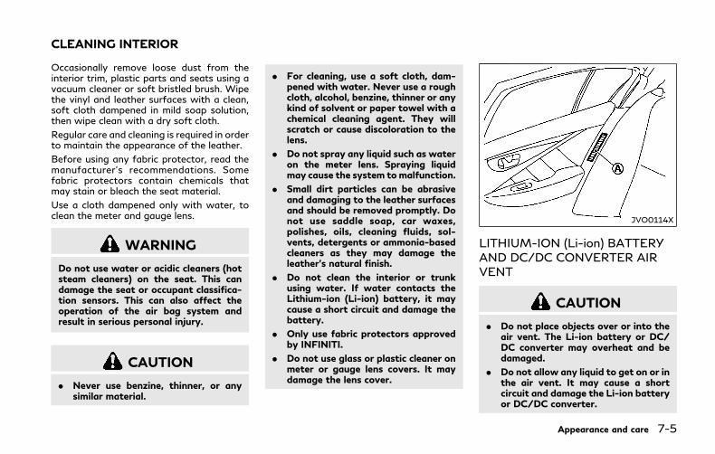
Occasionally remove loose dust from theinterior trim, plastic parts and seats using avacuum cleaner or soft bristled brush. Wipethe vinyl and leather surfaces with a clean,soft cloth dampened in mild soap solution,then wipe clean with a dry soft cloth.
Regular care and cleaning is required in orderto maintain the appearance of the leather.
Before using any fabric protector, read themanufacturer’s recommendations. Somefabric protectors contain chemicals thatmay stain or bleach the seat material.
Use a cloth dampened only with water, toclean the meter and gauge lens.
WARNING
Do not use water or acidic cleaners (hotsteam cleaners) on the seat. This candamage the seat or occupant classifica-tion sensors. This can also affect theoperation of the air bag system andresult in serious personal injury.
CAUTION
. Never use benzine, thinner, or anysimilar material.
. For cleaning, use a soft cloth, dam-pened with water. Never use a roughcloth, alcohol, benzine, thinner or anykind of solvent or paper towel with achemical cleaning agent. They willscratch or cause discoloration to thelens.
. Do not spray any liquid such as wateron the meter lens. Spraying liquidmay cause the system tomalfunction.
. Small dirt particles can be abrasiveand damaging to the leather surfacesand should be removed promptly. Donot use saddle soap, car waxes,polishes, oils, cleaning fluids, sol-vents, detergents or ammonia-basedcleaners as they may damage theleather’s natural finish.
. Do not clean the interior or trunkusing water. If water contacts theLithium-ion (Li-ion) battery, it maycause a short circuit and damage thebattery.
. Only use fabric protectors approvedby INFINITI.
. Do not use glass or plastic cleaner onmeter or gauge lens covers. It maydamage the lens cover.
JVO0114X
LITHIUM-ION (Li-ion) BATTERYAND DC/DC CONVERTER AIRVENT
CAUTION
. Do not place objects over or into theair vent. The Li-ion battery or DC/DC converter may overheat and bedamaged.
. Do not allow any liquid to get on or inthe air vent. It may cause a shortcircuit and damage the Li-ion batteryor DC/DC converter.
Appearance and care 7-5
CLEANING INTERIOR
7-6 Appearance and care
. Clean the air vent regularly to pre-vent the Li-ion battery or DC/DCconverter from overheating.
Regularly clean the air vent with a drycloth to prevent the vent from being blocked.
AIR FRESHENERSMost air fresheners use a solvent that couldaffect the vehicle interior. If you use an airfreshener, take the following precautions:
. Hanging-type air fresheners can causepermanent discoloration when they con-tact vehicle interior surfaces. Place theair freshener in a location that allows itto hang free and not contact an interiorsurface.
. Liquid-type air fresheners typically clipon the vents. These products can causeimmediate damage and discolorationwhen spilled on interior surfaces.
Carefully read and follow the manufac-turer’s instructions before using air fresh-eners.
FLOOR MATS
WARNING
To avoid potential pedal interferencethat may result in a collision, injury ordeath:
. NEVER place a floor mat on top ofanother floor mat in the driver frontposition or install them upside downor backwards.
. Use only genuine INFINITI floor matsor equivalent floor mats that arespecifically designed for use in yourvehicle model and model year.
. Properly position the mats in thefloorwell using the floor mat posi-tioning hook. See “Floor mat installa-tion” (P.7-7).
. Make sure the floor mat does notinterfere with pedal operation.
. Periodically check the floor mats tomake sure they are properly installed.
. After cleaning the vehicle interior,check the floor mats to make surethey are properly installed.
The use of genuine INFINITI floor mats canextend the life of your vehicle carpet and
make it easier to clean the interior. Matsshould be maintained with regular cleaningand replaced if they become excessivelyworn.
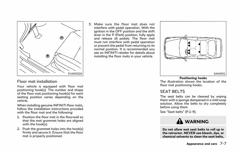
JVA0032X
Floor mat installationYour vehicle is equipped with floor matpositioning hook(s). The number and shapeof the floor mat positioning hook(s) for eachseating position varies depending on thevehicle.
When installing genuine INFINITI floor mats,follow the installation instructions providedwith the floor mat and the following:
1. Position the floor mat in the floorwell sothat the mat grommet holes are alignedwith the hook(s).
2. Push the grommet holes into the hook(s)firmly and secure it. Ensure that the floormat is properly positioned.
3. Make sure the floor mat does notinterfere with pedal operation. With theignition in the OFF position and the shiftlever in the P (Park) position, fully applyand release all pedals. The floor matmust not interfere with pedal operationor prevent the pedal from returning to itsnormal position. It is recommended yousee an INFINITI retailer for details aboutinstalling the floor mats in your vehicle.
SAI0051
Positioning hooksThe illustration shows the location of thefloor mat positioning hooks.
SEAT BELTSThe seat belts can be cleaned by wipingthemwith a sponge dampened in a mild soapsolution. Allow the belts to dry completelybefore using them.
See “Seat belts” (P.1-9).
WARNING
Do not allow wet seat belts to roll up inthe retractor. NEVER use bleach, dye, orchemical solvents to clean the seat belts,
Appearance and care 7-7

7-8 Appearance and care
since these materials may severelyweaken the seat belt webbing.
MOST COMMON FACTORSCONTRIBUTING TO VEHICLECORROSION. The accumulation of moisture-retaining
dirt and debris in body panel sections,cavities, and other areas.
. Damage to paint and other protectivecoatings caused by gravel and stonechips or minor traffic accidents.
ENVIRONMENTAL FACTORS IN-FLUENCE THE RATE OF COR-ROSION
MoistureAccumulation of sand, dirt and water on thevehicle body underside can accelerate corro-sion. Wet floor coverings will not drycompletely inside the vehicle, and should beremoved for drying to avoid floor panelcorrosion.
Relative humidityCorrosion will be accelerated in areas of highrelative humidity, especially those areaswhere the temperatures stay above freezingwhere atmospheric pollution exists, or whereroad salt is used.
TemperatureA temperature increase will accelerate therate of corrosion to those parts which arenot well ventilated.
Air pollutionIndustrial pollution, the presence of salt inthe air in coastal areas, or heavy road saltuse will accelerate the corrosion process.Road salt will also accelerate the disintegra-tion of paint surfaces.
TO PROTECT YOUR VEHICLEFROM CORROSION. Wash and wax your vehicle often to keep
the vehicle clean.
. Always check for minor damage to thepaint and repair it as soon as possible.
. Keep drain holes at the bottom of thedoors open to avoid water accumulation.
. Check the underbody for accumulation ofsand, dirt or salt. If present, wash withwater as soon as possible.
CAUTION
. NEVER remove dirt, sand or otherdebris from the passenger compart-ment by washing it out with a hose.Remove dirt with a vacuum cleaner.
CORROSION PROTECTION
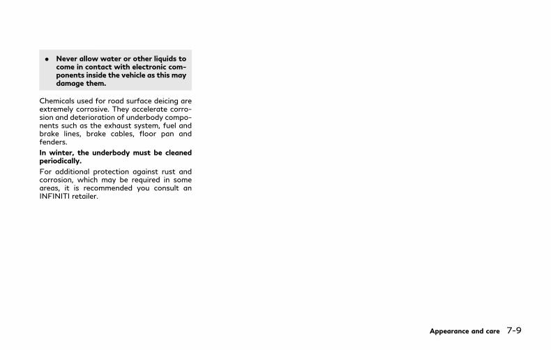
. Never allow water or other liquids tocome in contact with electronic com-ponents inside the vehicle as this maydamage them.
Chemicals used for road surface deicing areextremely corrosive. They accelerate corro-sion and deterioration of underbody compo-nents such as the exhaust system, fuel andbrake lines, brake cables, floor pan andfenders.
In winter, the underbody must be cleanedperiodically.
For additional protection against rust andcorrosion, which may be required in someareas, it is recommended you consult anINFINITI retailer.
Appearance and care 7-9

7-10 Appearance and care
MEMO

8 Do-it-yourself
Maintenance precautions................................................ 8-2
Engine compartment check locations ......................... 8-3
VQ35HR engine ........................................................... 8-3
Engine cooling system ..................................................... 8-5
Checking engine coolant level .................................. 8-6
Changing engine coolant ........................................... 8-7
Inverter cooling system ................................................... 8-7
Checking inverter coolant level ................................ 8-8
Changing inverter coolant ......................................... 8-9
Engine oil ............................................................................. 8-9
Checking engine oil level ............................................ 8-9
Changing engine oil and oil filter.......................... 8-10
Automatic Transmission Fluid (ATF) ......................... 8-12
Brake fluid ......................................................................... 8-12
Window washer fluid ..................................................... 8-13
12-volt battery ................................................................. 8-14
Checking battery fluid level .................................... 8-15
Jump starting .............................................................. 8-15
Spark plugs........................................................................ 8-15
Replacing spark plugs ............................................... 8-16
Air cleaner.......................................................................... 8-16
Windshield wiper blades ............................................... 8-17
Cleaning ...................................................................... 8-17
Replacing .................................................................... 8-18
Brakes ................................................................................ 8-18
Self-adjusting brakes .............................................. 8-18
Brake pad wear warning ....................................... 8-18
Fuses .................................................................................. 8-19
Engine compartment and trunk........................... 8-19
Passenger compartment....................................... 8-20
Intelligent Key battery replacement .......................... 8-21
Lights ................................................................................ 8-24
Headlights .................................................................. 8-25
Exterior and interior lights .................................... 8-25
Wheels and tires ............................................................ 8-28
Tire pressure............................................................. 8-28
Tire labeling ............................................................... 8-32
Types of tires ........................................................... 8-34
Tire chains .................................................................. 8-35
Changing wheels and tires .................................... 8-36
Jacking up the vehicle and replacing tires ........ 8-39

8-2 Do-it-yourself
When performing any inspection or main-tenance work on your vehicle, always takecare to prevent serious accidental injury toyourself or damage to the vehicle. Thefollowing are general precautions whichshould be closely observed.
WARNING
. This vehicle has high voltage DC andAC systems as well as a 12-voltsystem. DC and AC high voltage isvery dangerous and can cause severeburns and electric shock that mayresult in serious injury or death.
. Never touch, disassemble, remove orreplace the high voltage parts, har-nesses and their connectors. Highvoltage cables are orange. Touching,disassembling, removing or replacingthose parts and harnesses can causesevere burns or electric shock thatmay result in serious injury or death.
. Never try to remove the service pluglocated in the trunk room. The serviceplug is used only when the vehicle isserviced by trained technicians wear-ing personal protection equipmentand is part of the high voltagesystem. Touching the service plugcan cause severe burns or electric
shock that may result in serious injuryor death.
. The INFINITI Direct Response Hy-brid® System uses high voltage up to408 volts. The system can be hotwhile and after starting. Be careful ofboth the high voltage and the hightemperature. Obey the caution labelsattached to the vehicle.
. Park the vehicle on a level surface,apply the parking brake securely andblock the wheels to prevent thevehicle from moving. Move the shiftlever to P (Park).
. Be sure the ignition switch is in theOFF or LOCK position when per-forming any parts replacement orrepairs.
. The engine can start at any timewithout warning when the hybridsystem is in the READY to drivemode. If you must work with thehybrid system in the READY to drivemode, keep your hands, clothing, hairand tools away from fans, belts andany other parts that can move.
. It is advisable to secure or removeany loose clothing and remove anyjewelry, such as rings, watches, etc.before working on your vehicle.
. Always wear eye protection when-ever you work on your vehicle.
. Your vehicle is equipped with anautomatic engine cooling fan. It maycome on at any time without warn-ing, even if the ignition key is in theOFF position and the engine is notrunning. To avoid injury, always dis-connect the negative battery cable ofthe 12-volt battery before workingnear the fan.
. If you must run the engine in anenclosed space such as a garage, besure there is proper ventilation forexhaust gases to escape.
. Never get under the vehicle while it issupported only by a jack. If it isnecessary to work under the vehicle,support it with safety stands.
. Keep smoking materials, flame andsparks away from the fuel tank andthe 12-volt battery.
CAUTION
. Do notwork under the hoodwhile theengine is hot. Turn the hybrid systemoff and wait until it cools down.
MAINTENANCE PRECAUTIONS

. Avoid direct contact with used en-gine oil and coolant. Improperly dis-posed engine oil, coolant, and/orother vehicle fluids can damage theenvironment. Always conform to lo-cal regulations for disposal of vehiclefluid.
. Never leave the engine or the trans-mission related component harnessconnector disconnected while theignition switch is in the ON position.
. Never connect or disconnect the 12-volt battery or any transistorizedcomponent while the ignition switchis in the ON position.
This “8. Do-it-yourself” section gives in-structions regarding only those items whichare relatively easy for an owner to perform.
A genuine INFINITI Service Manual is alsoavailable. (See “Owner’s Manual/ServiceManual order information” (P.10-22).)
You should be aware that incomplete orimproper servicing may result in operatingdifficulties or excessive emissions, and couldaffect your warranty coverage. If in doubtabout any servicing, it is recommended youhave it done by an INFINITI retailer.
JVM0249X
VQ35HR ENGINETo remove the engine compartment cover,unhook the clips located as illustrated.
Do-it-yourself 8-3
ENGINE COMPARTMENT CHECKLOCATIONS

8-4 Do-it-yourself
JVM0294X
1. Engine oil filler cap
2. Brake fluid reservoir
3. Fuse/fusible link holder
4. Air cleaner
5. Inverter coolant reservoir
6. Radiator filler cap
7. Engine coolant reservoir
8. Engine oil dipstick
9. Window washer fluid reservoir
The 12-volt battery is located inside thetrunk.
The engine cooling system is filled at thefactory with a pre-diluted mixture of 50%Genuine NISSAN Long Life Antifreeze/Coolant (blue) and 50% water to provideyear-round anti-freeze and coolant protec-tion. The anti-freeze solution contains rustand corrosion inhibitors. Additional enginecooling system additives are not necessary.
WARNING
. Never remove the radiator cap whenthe engine is hot. Wait until theengine and radiator cool down. Ser-ious burns could be caused by highpressure fluid escaping from theradiator. See precautions in “If yourvehicle overheats” (P.6-8) of thismanual.
. The radiator is equipped with apressure type radiator cap. To pre-vent engine damage, use only agenuine NISSAN radiator cap.
CAUTION
. Never use any cooling system addi-tives such as radiator sealer. Addi-tives may clog the cooling system andcause damage to the engine, trans-
mission and/or cooling system.
. When adding or replacing coolant, besure to use only Genuine NISSANLong Life Antifreeze/Coolant (blue)or equivalent. Genuine NISSAN LongLife Antifreeze/Coolant (blue) is pre-diluted to provide antifreeze protec-tion to −34°F(−37°C). If additionalfreeze protection is needed due toweather where you operate yourvehicle, add Genuine NISSAN LongLife Antifreeze/Coolant (blue) con-centrate following the directions onthe container. If an equivalent cool-ant other than Genuine NISSAN LongLife Antifreeze/Coolant (blue) isused, follow the coolant manufac-ture’s instructions to maintain mini-mum antifreeze protection to −34°F(−37°C). The use of other types ofcoolant solutions other than GenuineNISSAN Long Life Antifreeze/Cool-ant (blue) or equivalent may damagethe engine cooling system.
. The life expectancy of the factory-fillcoolant is 105,000 miles (168,000km) or 7 years. Mixing any other typeof coolant other than GenuineNISSAN Long Life Antifreeze/Cool-ant (blue), including Genuine NISSANLong Life Antifreeze/ Coolant(green), or the use of non-distilled
water will reduce the life expectancyof the factory-fill coolant. Refer tothe “9. Maintenance and schedules”section of this manual for more de-tails.
Do-it-yourself 8-5
ENGINE COOLING SYSTEM
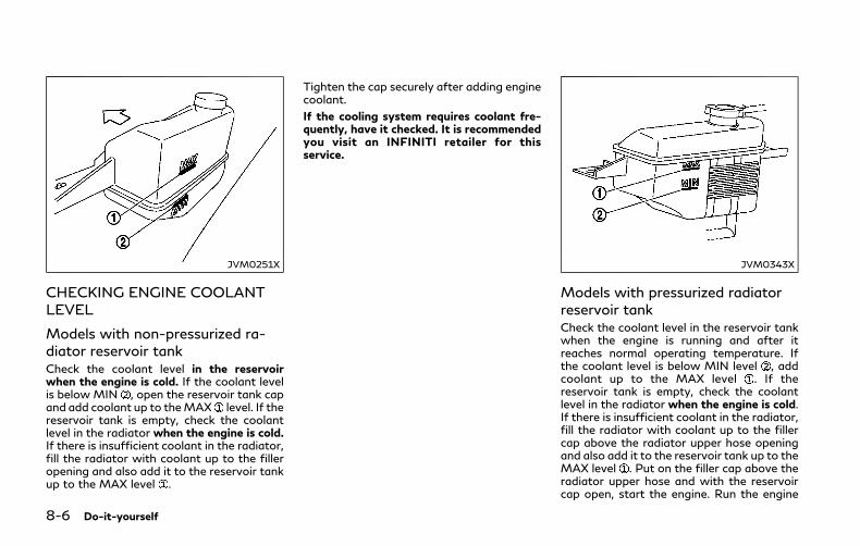
8-6 Do-it-yourself
JVM0251X
CHECKING ENGINE COOLANTLEVEL
Models with non-pressurized ra-diator reservoir tankCheck the coolant level in the reservoirwhen the engine is cold. If the coolant levelis below MIN , open the reservoir tank capand add coolant up to theMAX level. If thereservoir tank is empty, check the coolantlevel in the radiator when the engine is cold.If there is insufficient coolant in the radiator,fill the radiator with coolant up to the filleropening and also add it to the reservoir tankup to the MAX level .
Tighten the cap securely after adding enginecoolant.
If the cooling system requires coolant fre-quently, have it checked. It is recommendedyou visit an INFINITI retailer for thisservice.
JVM0343X
Models with pressurized radiatorreservoir tankCheck the coolant level in the reservoir tankwhen the engine is running and after itreaches normal operating temperature. Ifthe coolant level is below MIN level , addcoolant up to the MAX level . If thereservoir tank is empty, check the coolantlevel in the radiator when the engine is cold.If there is insufficient coolant in the radiator,fill the radiator with coolant up to the fillercap above the radiator upper hose openingand also add it to the reservoir tank up to theMAX level . Put on the filler cap above theradiator upper hose and with the reservoircap open, start the engine. Run the engine

until it reaches normal operating tempera-ture. Add coolant up to the MAX level .Tighten the cap securely after adding enginecoolant.
If the cooling system requires coolant fre-quently, have it checked. It is recommendedyou visit an INFINITI retailer for thisservice.
CHANGING ENGINE COOLANTIt is recommended that major cooling systemrepairs be performed by an INFINITI retailer.The service procedures can be found in theappropriate INFINITI Service Manual.
Improper servicing can result in reducedheater performance and engine overheat-ing.
WARNING
. To avoid the danger of being scalded,never change the coolant when theengine is hot.
. Never remove the radiator cap whenthe engine is hot. Serious burns couldbe caused by high pressure fluidescaping from the radiator.
. Avoid direct skin contact with usedcoolant. If skin contact is made, washthoroughly with soap or hand cleaner
as soon as possible.
. Keep coolant out of reach of childrenand pets.
Engine coolant must be disposed of prop-erly. Check your local regulations.
The inverter cooling system is filled at thefactory with a pre-diluted mixture of 50%Genuine NISSAN Long Life Antifreeze/Coolant (blue) and 50% water to provideyear-round anti-freeze and coolant protec-tion. The antifreeze solution contains rustand corrosion inhibitors. Additional invertercooling system additives are not necessary.
WARNING
. Never remove the inverter coolantreservoir cap when the engine andinverter are hot.Wait until the engineand inverter cool down. Serious burnscould be caused by high pressure fluidescaping from the coolant reservoir.
. The inverter coolant reservoir isequipped with a pressure type cap.To prevent engine and inverter da-mage, use only a genuine NISSANinverter reservoir cap.
CAUTION
. Never use any additives in the cool-ant such as radiator sealer in thecooling system. This may cause da-mage to electrical equipment such asthe motor and inverter, and also to
Do-it-yourself 8-7
INVERTER COOLING SYSTEM
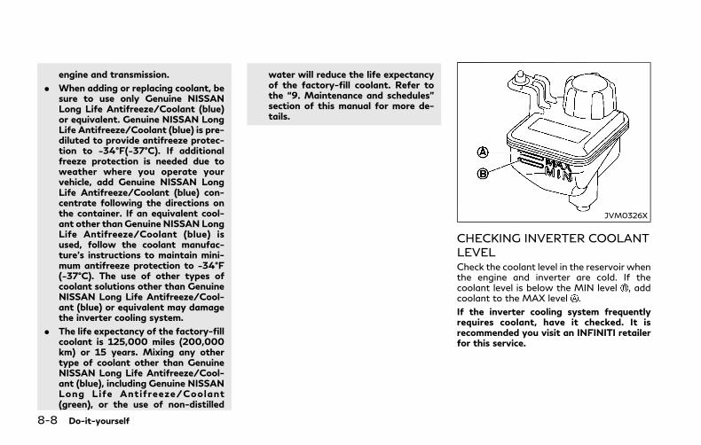
8-8 Do-it-yourself
engine and transmission.
. When adding or replacing coolant, besure to use only Genuine NISSANLong Life Antifreeze/Coolant (blue)or equivalent. Genuine NISSAN LongLife Antifreeze/Coolant (blue) is pre-diluted to provide antifreeze protec-tion to −34°F(−37°C). If additionalfreeze protection is needed due toweather where you operate yourvehicle, add Genuine NISSAN LongLife Antifreeze/Coolant (blue) con-centrate following the directions onthe container. If an equivalent cool-ant other than Genuine NISSAN LongLife Antifreeze/Coolant (blue) isused, follow the coolant manufac-ture’s instructions to maintain mini-mum antifreeze protection to −34°F(−37°C). The use of other types ofcoolant solutions other than GenuineNISSAN Long Life Antifreeze/Cool-ant (blue) or equivalent may damagethe inverter cooling system.
. The life expectancy of the factory-fillcoolant is 125,000 miles (200,000km) or 15 years. Mixing any othertype of coolant other than GenuineNISSAN Long Life Antifreeze/Cool-ant (blue), including Genuine NISSANLong Life Antifreeze/Coolant(green), or the use of non-distilled
water will reduce the life expectancyof the factory-fill coolant. Refer tothe “9. Maintenance and schedules”section of this manual for more de-tails.
JVM0326X
CHECKING INVERTER COOLANTLEVELCheck the coolant level in the reservoir whenthe engine and inverter are cold. If thecoolant level is below the MIN level , addcoolant to the MAX level .
If the inverter cooling system frequentlyrequires coolant, have it checked. It isrecommended you visit an INFINITI retailerfor this service.

CHANGING INVERTER COOLANTAn INFINITI ratailer can change the invertercoolant. The service procedure can be foundin the INFINITI Service Manual.
Improper servicing can result in inverteroverheating.
WARNING
. To avoid the danger of being scalded,never change the coolant when theinverter is hot.
. Never remove the cap when theinverter is hot. Serious burns couldbe caused by high pressure fluidescaping from the inverter coolantreservoir.
. Avoid direct skin contact with usedcoolant. If skin contact is made, washthoroughly with soap or hand cleaneras soon as possible.
. Keep coolant out of the reach ofchildren and pets.
Inverter coolant must be disposed of prop-erly. Check your local regulations.
SDI2045
CHECKING ENGINE OIL LEVEL1. Park the vehicle on a level surface and
apply the parking brake.
2. Run the engine until it reaches operatingtemperature.
3. Turn off the engine. Wait more than 15minutes for the oil to drain back into theoil pan.
4. Remove the dipstick and wipe it clean.Reinsert it all the way.
5. Remove the dipstick again and check theoil level. It should be within the range .If the oil level is below , remove the oilfiller cap and pour recommended oilthrough the opening. Do not overfill .
6. Recheck oil level with the dipstick.
It is normal to add some oil between oilmaintenance intervals or during the break-in period, depending on the severity ofoperating conditions.
CAUTION
Oil level should be checked regularly.Operating the engine with an insuffi-cient amount of oil can damage theengine, and such damage is not coveredby warranty.
Do-it-yourself 8-9
ENGINE OIL
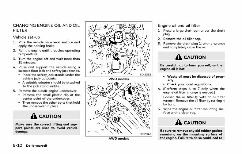
8-10 Do-it-yourself
CHANGING ENGINE OIL AND OILFILTER
Vehicle set-up1. Park the vehicle on a level surface and
apply the parking brake.
2. Run the engine until it reaches operatingtemperature.
3. Turn the engine off and wait more than15 minutes.
4. Raise and support the vehicle using asuitable floor jack and safety jack stands.. Place the safety jack stands under the
vehicle jack-up points.. A suitable adapter should be attached
to the jack stand saddle.
5. Remove the plastic engine undercover.. Remove the small plastic clip at the
center point of the undercover.. Then remove the other bolts that hold
the undercover in place.
CAUTION
Make sure the correct lifting and sup-port points are used to avoid vehicledamage.
SDI2335
2WD models
SDI2047
AWD models
Engine oil and oil filter1. Place a large drain pan under the drain
plug.
2. Remove the oil filler cap.
3. Remove the drain plug with a wrenchand completely drain the oil.
CAUTION
Be careful not to burn yourself, as theengine oil is hot.
. Waste oil must be disposed of prop-erly.
. Check your local regulations.
4. (Perform steps 4 to 7 only when theengine oil filter change is needed.)
Loosen the oil filter with an oil filterwrench. Remove the oil filter by turning itby hand.
5. Wipe the engine oil filter mounting sur-face with a clean rag.
CAUTION
Be sure to remove any old rubber gasketremaining on the mounting surface ofthe engine. Failure to do so could lead to

engine damage.
6. Coat the gasket on the new filter withclean engine oil.
7. Screw in the oil filter clockwise until aslight resistance is felt, then tightenadditionally more than 2/3 turn.
Oil filter tightening torque:11 to 15 ft-lb(14.7 to 20.5 N·m)
8. Clean and re-install the drain plug with anew washer. Securely tighten the drainplug with a wrench.
Drain plug tightening torque:22 to 29 ft-lb(29 to 39 N·m)
Do not use excessive force.
9. Refill engine with recommended oil andinstall the oil filler cap securely.
CAUTION
The dipstick must be inserted in place toprevent oil spillage from the dipstickhole while filling the engine with oil.
See “Capacities and recommendedfluids/lubricants” (P.10-2) for drain and
refill capacity. The drain and refill capa-city depends on the oil temperature anddrain time. Use these specifications forreference only. Always use the dipstickto determine the proper amount of oil inthe engine.
10.Start the engine and check for leakagearound the drain plug and the oil filter.Correct as required.
11. Turn the engine off and wait more than15 minutes. Check the oil level with thedipstick. Add engine oil if necessary.
After the operation1. Install the engine undercover into posi-
tion as the following steps.
a. Pull the center of the small plastic clipout.
b. Hold the engine undercover into posi-tion.
c. Insert the clip through the undercoverinto the hole in the frame, then pushthe center of the clip in to lock the clipin place.
d. Install the other bolts that hold theundercover in place. Be careful not tostrip the bolts or over-tighten them.
2. Lower the vehicle carefully to theground.
3. Dispose of waste oil and filter properly.
WARNING
. Prolonged and repeated contact withused engine oil may cause skin cancer.
. Try to avoid direct skin contact withused oil. If skin contact is made, washthoroughly with soap or hand cleaneras soon as possible.
. Keep used engine oil out of reach ofchildren.
Do-it-yourself 8-11
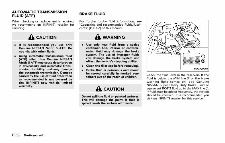
8-12 Do-it-yourself
When checking or replacement is required,we recommend an INFINITI retailer forservicing.
CAUTION
. It is recommended you use onlyGenuine NISSAN Matic S ATF. Donot mix with other fluids.
. Using automatic transmission fluid(ATF) other than Genuine NISSANMatic S ATF may cause deteriorationin driveability and automatic trans-mission durability, and may damagethe automatic transmission. Damagecaused by the use of fluid other thanas recommended is not covered bythe INFINITI new vehicle limitedwarranty.
For further brake fluid information, see“Capacities and recommended fluids/lubri-cants” (P.10-2) of this manual.
WARNING
. Use only new fluid from a sealedcontainer. Old, inferior or contami-nated fluid may damage the brakesystem. The use of improper fluidscan damage the brake system andaffect the vehicle’s stopping ability.
. Clean the filler cap before removing.
. Brake fluid is poisonous and shouldbe stored carefully in marked con-tainers out of the reach of children.
CAUTION
Do not spill the fluid on painted surfaces.This will damage the paint. If fluid isspilled, wash the surface with water.
JVM0053X
Check the fluid level in the reservoir. If thefluid is below the MIN line or the brakewarning light comes on, add GenuineNISSAN Super Heavy Duty Brake Fluid orequivalentDOT 3 fluid up to theMAX line .If fluid must be added frequently, the systemshould be checked. It is recommended youvisit an INFINITI retailer for this service.
AUTOMATIC TRANSMISSIONFLUID (ATF) BRAKE FLUID

JVM0253X
WARNING
Antifreeze is poisonous and should bestored carefully in marked containersout of the reach of children.
Fill the window washer fluid reservoir per-iodically. Add windowwasher fluid when thelowwindowwasher fluid warning appears inthe vehicle information display.
To fill the window washer fluid reservoir, liftthe cap off the reservoir and pour thewindow washer fluid into the reservoiropening.
To check the window washer fluid level, useyour finger to plug the hole of the cap/tube assembly, then remove it from thereservoir. If there is no fluid in the tube,add fluid.
Add a washer solvent to the washer forbetter cleaning. In the winter season, add awindshield washer antifreeze. Follow themanufacturer’s instructions for the mixtureratio.
Refill the reservoir more frequently whendriving conditions require an increasedamount of window washer fluid.
Recommended fluid is Genuine NISSANWindshield Washer Concentrate Cleaner &Antifreeze or equivalent.
CAUTION
. Do not substitute engine anti-freezecoolant for window washer solution.This may result in damage to thepaint.
. Do not fill the window washer re-servoir with washer fluid concen-trates at full strength. Some methylalcohol based washer fluid concen-trates may permanently stain thegrille if spilled while filling the win-dow washer reservoir.
. Pre-mix washer fluid concentrateswith water to the manufacturer’srecommended levels before pouringthe fluid into the window washerreservoir. Do not use the windowwasher reservoir to mix the washerfluid concentrate and water.
Do-it-yourself 8-13
WINDOW WASHER FLUID

8-14 Do-it-yourself
JVM0295X
The 12-volt battery is located on the lefthand side of the trunk behind an accesspanel.
. Keep the battery surface clean and dry.Clean the battery with a solution ofbaking soda and water.
. Make certain the terminal connectionsare clean and securely tightened.
. If the vehicle is not to be used for 30 daysor longer, disconnect the negative (-)battery terminal cable to prevent dis-charging it.
NOTE:
Care should be taken to avoid situationsthat can lead to potential 12-volt battery
discharge and potential no-start conditionssuch as:1. Installation or extended use of electro-
nic accessories that consume 12-voltbattery power when the engine is notrunning (Phone chargers, GPS, DVDplayers, etc.)
2. Vehicle is not driven regularly and/oronly driven short distances.
In these cases, the 12-volt battery mayneed to be charged to maintain 12-voltbattery health.
WARNING
. Do not expose the 12-volt battery toflames or electrical sparks. Hydrogengas generated by the 12-volt batteryis explosive. Do not allow batteryfluid to contact your skin, eyes,fabrics or painted surfaces. Aftertouching a 12-volt battery, do nottouch or rub your eyes. Thoroughlywash your hands. If the acid contactsyour eyes, skin or clothing, immedi-ately flush with water for at least 15minutes and seek medical attention.
. The hybrid vehicle uses a specialbattery. If the 12-volt battery needsto be replaced, use a 12-volt batteryof the same design. Using the wrong
battery can cause hydrogen gas tobuild up in the vehicle, which couldlead to an explosion and personalinjury.
. When working on or near a 12-voltbattery, always wear suitable eyeprotection and remove all jewelry.
. Battery posts, terminals and relatedaccessories contain lead and leadcompounds. Wash hands after hand-ling.
. Keep the 12-volt battery out of thereach of children.
12-VOLT BATTERY
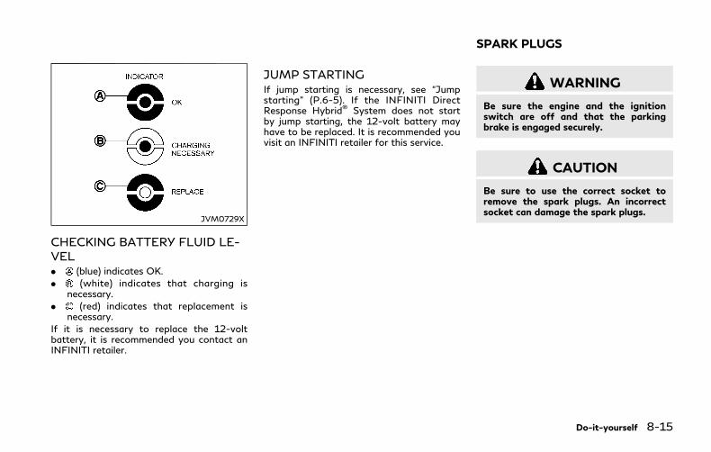
JVM0729X
CHECKING BATTERY FLUID LE-VEL. (blue) indicates OK.
. (white) indicates that charging isnecessary.
. (red) indicates that replacement isnecessary.
If it is necessary to replace the 12-voltbattery, it is recommended you contact anINFINITI retailer.
JUMP STARTINGIf jump starting is necessary, see “Jumpstarting” (P.6-5). If the INFINITI DirectResponse Hybrid® System does not startby jump starting, the 12-volt battery mayhave to be replaced. It is recommended youvisit an INFINITI retailer for this service.
WARNING
Be sure the engine and the ignitionswitch are off and that the parkingbrake is engaged securely.
CAUTION
Be sure to use the correct socket toremove the spark plugs. An incorrectsocket can damage the spark plugs.
Do-it-yourself 8-15
SPARK PLUGS

8-16 Do-it-yourself
SDI2020
REPLACING SPARK PLUGSIf replacement is required, it is recommendedyou visit an INFINITI retailer for this service.
Iridium-tipped spark plugsIt is not necessary to replace the iridium-tipped spark plugs as frequently as theconventional type spark plugs since they willlast much longer. Follow the maintenanceschedule in “9. Maintenance and schedules”section of this manual, but do not reusethem by cleaning or regapping.
Always replace spark plugs with recom-mended or equivalent ones.
JVM0254X
Remove the retainers as illustrated andpull out the filter element .
The filter element should not be cleaned andreused. Replace it according to the main-tenance schedule shown in the “9. Main-tenance and schedules” section. Whenreplacing the filter, wipe the inside of theair cleaner housing and the cover with a
AIR CLEANER

damp cloth.
WARNING
. Operating the engine with the aircleaner removed can cause you orothers to be burned. The air cleanernot only cleans the air, it stops flameif the engine backfires. If it isn’tthere, and the engine backfires, youcould be burned. Do not drive withthe air cleaner removed, and be care-ful when working on the engine withthe air cleaner removed.
. Never pour fuel into the throttle bodyor attempt to start the engine withthe air cleaner removed. Doing socould result in serious injury.
CLEANINGIf your windshield is not clear after using thewindshield washer or if a wiper bladechatters when running, wax or other materi-al may be on the blade or windshield.
Clean the outside of the windshield with awasher solution or a mild detergent. Yourwindshield is clean if beads do not formwhen rinsing with clear water.
Clean each blade by wiping it with a clothsoaked in a washer solution or a milddetergent. Then rinse the blade with clearwater. If your windshield is still not clearafter cleaning the blades and using thewiper, replace the blades.
Worn windshield wiper blades can damagethe windshield and impair driver vision.
When a washer nozzle is cloggedIf a washer nozzle is clogged or anymalfunction occurs, have it checked. It isrecommended you visit an INFINITI retailerfor this service. Do not attempt to clean thenozzle using a needle or a pin. Doing so maydamage the nozzle.
Do-it-yourself 8-17
WINDSHIELD WIPER BLADES

8-18 Do-it-yourself
SDI2048
REPLACINGReplace the wiper blades if they are worn.
Before replacing the wiper blades, the wipershould be in the fully up position to avoidscratching the engine hood or damaging thewiper arm. To pull up the wiper arm, see“Wiper and washer switch” (P.2-34).
1. Pull the wiper arm.
2. Push the release tab , and then movethe wiper blade down the wiper armwhile pushing the release tab to remove.
3. Insert the new wiper blade onto thewiper arm until a click sounds.
4. Rotate the wiper blade so the dimple is in
the groove.
CAUTION
. After wiper blade replacement, re-turn the wiper arm to its originalposition;
otherwise it may be damaged whenthe hood is opened.
. Make sure the wiper blades contactthe glass; otherwise the arm may bedamaged from wind pressure.
If the brakes do not operate properly, havethe brakes checked. It is recommended youvisit an INFINITI retailer for this service.
SELF-ADJUSTING BRAKESYour vehicle is equipped with self-adjustingbrakes.
The disc-type brakes self-adjust every timethe brake pedal is applied.
WARNING
Have your brake system checked if thebrake pedal height does not return tonormal. It is recommended you visit anINFINITI retailer for this service.
BRAKE PAD WEAR WARNINGThe disc brake pads have audible wearwarnings. When a brake pad requires repla-cement, it will make a high pitched scrapingsound when the vehicle is in motion. Thisscraping sound will first occur only when thebrake pedal is depressed. After more wear ofthe brake pad, the sound will always beheard even if the brake pedal is notdepressed. Have the brakes checked as soonas possible if the wear warning sound isheard.
BRAKES

Under some driving or climate conditions,occasional brake squeak, squeal or othernoise may be heard. Occasional brake noiseduring light to moderate stops is normal anddoes not affect the function or performanceof the brake system.
Proper brake inspection intervals should befollowed. For additional information, see themaintenance schedule shown in the “9.Maintenance and schedules” section.
JVM0255X
Engine compartment
JVM0322X
Trunk
ENGINE COMPARTMENT ANDTRUNK
WARNING
Never use a fuse of a higher or loweramperage rating than that specified onthe fuse box cover. This could damagethe electrical system or electronic con-trol units or cause a fire.
If any electrical equipment does not operate,check for an open fuse.
1. Be sure the ignition switch is pushed tothe OFF or LOCK position and theheadlight switch is turned to OFF.
2. Open the engine hood or trunk lid and toaccess the cover on the fuse/fusible linkholder.
3. Remove the fuse/fusible link holdercover.
4. Remove the fuse with the fuse puller.
Do-it-yourself 8-19
FUSES

8-20 Do-it-yourself
SDI1754
5. If the fuse is open , replace it with anew fuse . Spare fuses are stored in thepassenger compartment fuse box.
6. If a new fuse also opens, have theelectrical system checked and repaired.It is recommended you visit an INFINITIretailer for this service.
Fusible linksIf any electrical equipment does not operateand fuses are in good condition, check thefusible links. If any of these fusible links aremelted, replace only with genuine INFINITIparts.
JVM0256X
PASSENGER COMPARTMENT
WARNING
Never use a fuse of a higher or loweramperage rating than that specified onthe fuse box cover. This could damagethe electrical system or electronic con-trol units or cause a fire.
If any electrical equipment does not operate,check for an open fuse.
1. Be sure the ignition switch is pushed tothe OFF or LOCK position and theheadlight switch is turned to OFF.
2. Open the fuse box lid.
3. Remove the fuse with the fuse puller .
4. If the fuse is open, replace it with a newfuse.
5. If a new fuse also opens, have theelectrical system checked and repaired.It is recommended you visit an INFINITIretailer for this service. Spare fuses arestored in the fuse box.
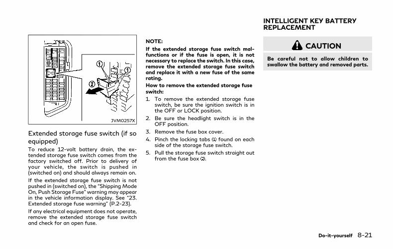
JVM0257X
Extended storage fuse switch (if soequipped)To reduce 12-volt battery drain, the ex-tended storage fuse switch comes from thefactory switched off. Prior to delivery ofyour vehicle, the switch is pushed in(switched on) and should always remain on.
If the extended storage fuse switch is notpushed in (switched on), the “Shipping ModeOn, Push Storage Fuse”warningmay appearin the vehicle information display. See “23.Extended storage fuse warning” (P.2-23).
If any electrical equipment does not operate,remove the extended storage fuse switchand check for an open fuse.
NOTE:
If the extended storage fuse switch mal-functions or if the fuse is open, it is notnecessary to replace the switch. In this case,remove the extended storage fuse switchand replace it with a new fuse of the samerating.
How to remove the extended storage fuseswitch:
1. To remove the extended storage fuseswitch, be sure the ignition switch is inthe OFF or LOCK position.
2. Be sure the headlight switch is in theOFF position.
3. Remove the fuse box cover.
4. Pinch the locking tabs found on eachside of the storage fuse switch.
5. Pull the storage fuse switch straight outfrom the fuse box .
CAUTION
Be careful not to allow children toswallow the battery and removed parts.
Do-it-yourself 8-21
INTELLIGENT KEY BATTERYREPLACEMENT
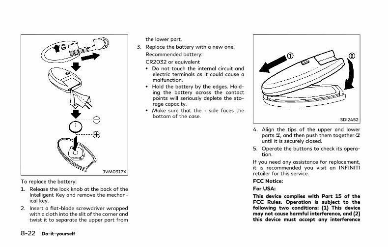
8-22 Do-it-yourself
JVM0317X
To replace the battery:
1. Release the lock knob at the back of theIntelligent Key and remove the mechan-ical key.
2. Insert a flat-blade screwdriver wrappedwith a cloth into the slit of the corner andtwist it to separate the upper part from
the lower part.
3. Replace the battery with a new one.
Recommended battery:
CR2032 or equivalent. Do not touch the internal circuit and
electric terminals as it could cause amalfunction.
. Hold the battery by the edges. Hold-ing the battery across the contactpoints will seriously deplete the sto-rage capacity.
. Make sure that the + side faces thebottom of the case.
SDI2452
4. Align the tips of the upper and lowerparts , and then push them togetheruntil it is securely closed.
5. Operate the buttons to check its opera-tion.
If you need any assistance for replacement,it is recommended you visit an INFINITIretailer for this service.
FCC Notice:
For USA:
This device complies with Part 15 of theFCC Rules. Operation is subject to thefollowing two conditions: (1) This devicemay not cause harmful interference, and (2)this device must accept any interference

received, including interference that maycause undesired operation.
NOTE:
Changes or modifications not expresslyapproved by the party responsible forcompliance could void the user’s authorityto operate the equipment.
For Canada:
This device complies with Industry Canadalicence-exempt RSS standard(s). Operationis subject to the following two conditions:(1) this device may not cause interference,and (2) this device must accept any inter-ference, including interference that maycause undesired operation of the device.
Do-it-yourself 8-23
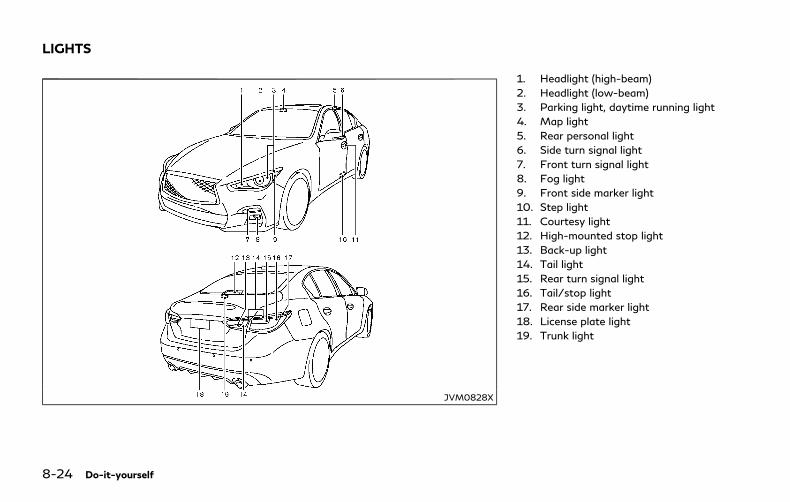
8-24 Do-it-yourself
JVM0828X
1. Headlight (high-beam)
2. Headlight (low-beam)
3. Parking light, daytime running light
4. Map light
5. Rear personal light
6. Side turn signal light
7. Front turn signal light
8. Fog light
9. Front side marker light
10. Step light
11. Courtesy light
12. High-mounted stop light
13. Back-up light
14. Tail light
15. Rear turn signal light
16. Tail/stop light
17. Rear side marker light
18. License plate light
19. Trunk light
LIGHTS

HEADLIGHTSIf replacement is required, it is recommendedyou visit your INFINITI retailer for thisservice.
Fog may temporarily form inside the lens ofthe exterior lights in the rain or in a car wash.A temperature difference between the insideand the outside of the lens causes the fog.This is not a malfunction. If large drops ofwater collect inside the lens, it is recom-mended you visit your INFINITI retailer forthis service.
EXTERIOR AND INTERIOR LIGHTS
Item Wattage (W) Bulb No.
Headlight*
High/Low beams LED —
Front turn signal light* LED —
Front fog light* LED —
Parking light*/Daytime running light* LED —
Front side marker light* LED —
Side turn signal light* LED —
Rear combination light*
back-up LED —
turn signal LED —
tail LED —
tail/stop LED —
side marker LED —
License plate light* LED —
Map light* LED —
Rear personal light 8 —
Vanity mirror light* 1.8 —
Step light 5 —
Console box light* 2 —
Inside door handle light* (if so equipped) LED —
Door trim light* (if so equipped) LED —
Front cup holder light* LED —
Footwell light* LED —
Trunk light 3.4 —
Do-it-yourself 8-25
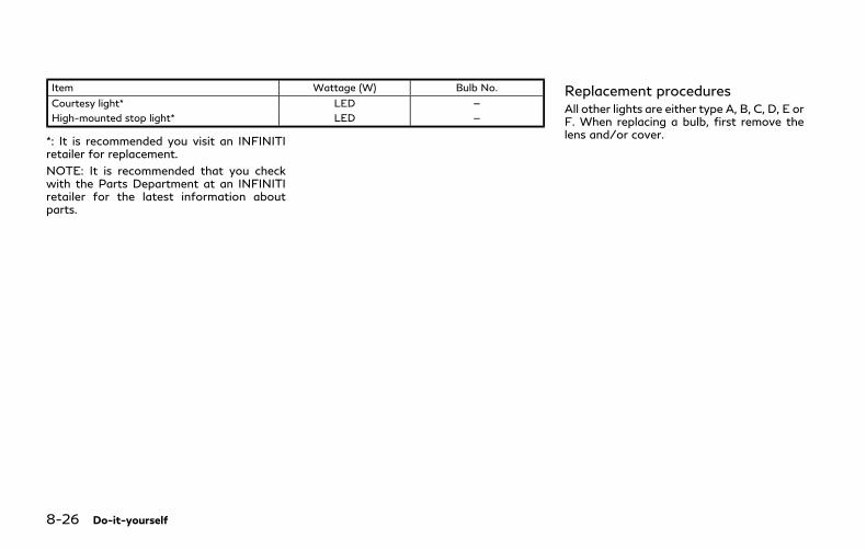
8-26 Do-it-yourself
Item Wattage (W) Bulb No.
Courtesy light* LED —
High-mounted stop light* LED —
*: It is recommended you visit an INFINITIretailer for replacement.
NOTE: It is recommended that you checkwith the Parts Department at an INFINITIretailer for the latest information aboutparts.
Replacement proceduresAll other lights are either type A, B, C, D, E orF. When replacing a bulb, first remove thelens and/or cover.
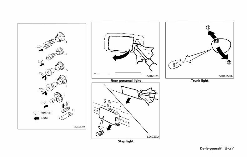
SDI1679
SDI2031
Rear personal light
SDI2330
Step light
SDI1258A
Trunk light
Do-it-yourself 8-27

8-28 Do-it-yourself
If you have a flat tire, see “Flat tire” (P.6-3).
TIRE PRESSURE
Tire Pressure Monitoring System(TPMS)This vehicle is equipped with the TirePressure Monitoring System (TPMS). Itmonitors tire pressure of all tires except thespare. When the low tire pressure warninglight is lit and the “Tire Pressure Low - AddAir” warning appears in the vehicle informa-tion display, one or more of your tires issignificantly under-inflated.
The TPMS will activate only when thevehicle is driven at speeds above 16 MPH(25 km/h). Also, this system may not detecta sudden drop in tire pressure (for example aflat tire while driving).
For more details, see “Low tire pressurewarning light” (P.2-12),“Tire Pressure Mon-itoring System (TPMS)” (P.5-5) and “TirePressure Monitoring System (TPMS)” (P.6-3).
Tire inflation pressure
Check the pressure of the tires (in-cluding the spare) often and alwaysprior to long distance trips. Therecommended tire pressure specifica-tions are shown on the Tire and
Loading Information label under the“Cold Tire Pressure” heading. The Tireand Loading Information label isaffixed to the driver side center pillar.Tire pressures should be checkedregularly because:
. Most tires naturally lose air overtime.
. Tires can lose air suddenly whendriven over potholes or other ob-jects or if the vehicle strikes a curbwhile parking.
The tire pressures should be checkedwhen the tires are cold. The tires areconsidered COLD after the vehiclehas been parked for 3 or more hours,or driven less than 1 mile (1.6 km) atmoderate speeds.
TPMS with Tire Inflation Indicatorprovides visual and audible signalsoutside the vehicle for inflating thetires to the recommended COLD tirepressure. (See “TPMS with Tire Infla-tion Indicator” (P.5-8) about theTPMS with Tire Inflation Indicator.)
Incorrect tire pressure, including un-der inflation, may adversely affect
tire life and vehicle handling.
WARNING
. Improperly inflated tires can failsuddenly and cause an accident.
. The Gross Vehicle Weight rat-ing (GVWR) is located on the F.M.V.S.S./C.M.V.S.S. label. Thevehicle weight capacity is indi-cated on the Tire and LoadingInformation label. Do not loadyour vehicle beyond this capa-city. Overloading your vehiclemay result in reduced tire life,unsafe operating conditionsdue to premature tire failure,or unfavorable handling char-acteristics and could also leadto a serious accident. Loadingbeyond the specified capacitymay also result in failure ofother vehicle components.
. Before taking a long trip, orwhenever you heavily load yourvehicle, use a tire pressuregauge to ensure that the tire
WHEELS AND TIRES
pressures are at the specifiedlevel.
. For additional information re-garding tires, refer to “Impor-tant Tire Safety Information”(US) or “Tire Safety Informa-tion” (Canada) in the WarrantyInformation Booklet.
Do-it-yourself 8-29
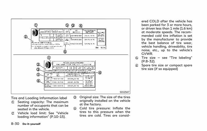
8-30 Do-it-yourself
SDI2567
Tire and Loading Information labelSeating capacity: The maximumnumber of occupants that can beseated in the vehicle.Vehicle load limit: See “Vehicleloading information” (P.10-15).
Original size: The size of the tiresoriginally installed on the vehicleat the factory.Cold tire pressure: Inflate thetires to this pressure when thetires are cold. Tires are consid-
ered COLD after the vehicle hasbeen parked for 3 or more hours,or driven less than 1 mile (1.6 km)at moderate speeds. The recom-mended cold tire inflation is setby the manufacturer to providethe best balance of tire wear,vehicle handling, driveability, tirenoise, etc., up to the vehicle’sGVWR.Tire size — see “Tire labeling”(P.8-32).Spare tire size or compact sparetire size (if so equipped)
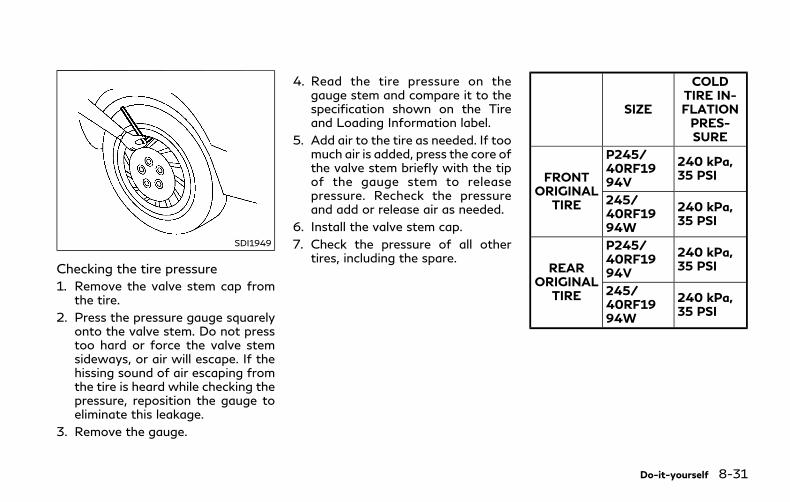
SDI1949
Checking the tire pressure
1. Remove the valve stem cap fromthe tire.
2. Press the pressure gauge squarelyonto the valve stem. Do not presstoo hard or force the valve stemsideways, or air will escape. If thehissing sound of air escaping fromthe tire is heard while checking thepressure, reposition the gauge toeliminate this leakage.
3. Remove the gauge.
4. Read the tire pressure on thegauge stem and compare it to thespecification shown on the Tireand Loading Information label.
5. Add air to the tire as needed. If toomuch air is added, press the core ofthe valve stem briefly with the tipof the gauge stem to releasepressure. Recheck the pressureand add or release air as needed.
6. Install the valve stem cap.
7. Check the pressure of all othertires, including the spare.
SIZE
COLDTIRE IN-FLATIONPRES-SURE
FRONTORIGINAL
TIRE
P245/40RF1994V
240 kPa,35 PSI
245/40RF1994W
240 kPa,35 PSI
REARORIGINAL
TIRE
P245/40RF1994V
240 kPa,35 PSI
245/40RF1994W
240 kPa,35 PSI
Do-it-yourself 8-31

8-32 Do-it-yourself
SDI1575
Example
TIRE LABELING
Federal law requires tire manufac-turers to place standardized informa-tion on the sidewall of all tires. Thisinformation identifies and describesthe fundamental characteristics ofthe tire and also provides the tireidentification number (TIN) for safetystandard certification. The TIN can beused to identify the tire in case of arecall.
SDI1606
ExampleTire size (example: P215/60R16
94H)
1. P: The “P” indicates the tire isdesigned for passenger vehicles.(Not all tires have this informa-tion.)
2. Three-digit number (215): Thisnumber gives the width in milli-meters of the tire from sidewalledge to sidewall edge.
3. Two-digit number (60): This num-ber, known as the aspect ratio,gives the tire’s ratio of height to
width.
4. R: The “R” stands for radial.
F: The “F” after “R” indicates Self-Supporting type run-flat tire.
5. Two-digit number (16): This num-ber is the wheel or rim diameter ininches.
6. Two- or three-digit number (94):This number is the tire’s load index.It is a measurement of how muchweight each tire can support. Youmay not find this information on alltires because it is not required bylaw.
7. H: Tire speed rating. You shouldnot drive the vehicle faster thanthe tire speed rating.

JVM0694X
ExampleTIN (Tire Identification Number) for
a new tire (example: DOT XX XX XXXXXXX)
1. DOT: Abbreviation for the “De-partment of Transportation”. Thesymbol can be placed above, be-low or to the left or right of theTire Identification Number.
2. Two-digit code: Manufacturer’sidentification mark
3. Two-digit code: Tire size
4. Three-digit code: Tire type code(Optional)
5. Four numbers represent the weekand year the tire was built. Forexample, the numbers 3103means the 31st week of 2003. Ifthese numbers are missing, thenlook on the other sidewall of thetire.
Tire ply composition and material
The number of layers or plies ofrubber-coated fabric in the tire.
Tire manufacturers also must indicatethe materials in the tire, which includesteel, nylon, polyester, and others.
Maximum permissible inflationpressure
This number is the greatest amount ofair pressure that should be put in thetire. Do not exceed the maximumpermissible inflation pressure.
Maximum load rating
This number indicates the maximumload in kilograms and pounds that canbe carried by the tire. When replacingthe tires on the vehicle, always use atire that has the same load rating asthe factory installed tire.
Term of “tubeless” or “tube type”
Indicates whether the tire requires aninner tube (“tube type”) or not (“tube-less”).
The word “radial”
The word “radial” is shown, if the tirehas radial structure.
Manufacturer or brand name
Manufacturer or brand name isshown.
Other tire-related terminology:
In addition to the many terms that aredefined throughout this section, In-tended Outboard Sidewall is (1) thesidewall that contains a whitewall,bears white lettering or bears manu-facturer, brand and/or model namemolding that is higher or deeper thanthe same molding on the other side-wall of the tire, or (2) the outwardfacing sidewall of an asymmetricaltire that has a particular side thatmust always face outward whenmounted on a vehicle.
Do-it-yourself 8-33

8-34 Do-it-yourself
TYPES OF TIRES
WARNING
. When changing or replacing tires, besure all four tires are of the same type(Example: Summer, All Season orSnow) and construction. An INFINITIretailer may be able to help you withinformation about tire type, size,speed rating and availability.
. Replacement tires may have a lowerspeed rating than the factoryequipped tires, and may not matchthe potential maximum vehicle speed.Never exceed the maximum speedrating of the tire.
. Replacing tires with those not origin-ally specified by INFINITI could affectthe proper operation of the TPMS.
. For additional information regardingtires, refer to “Important Tire SafetyInformation” (US) or “Tire SafetyInformation” (Canada) in the War-ranty Information Booklet.
All season tiresINFINITI specifies all season tires on somemodels to provide good performance all
year, including snowy and icy road condi-tions. All Season tires are identified by ALLSEASON and/or M&S (Mud and Snow) onthe tire sidewall. Snow tires have bettersnow traction than All Season tires and maybe more appropriate in some areas.
Summer tiresINFINITI specifies summer tires on somemodels to provide superior performance ondry roads. Summer tire performance issubstantially reduced in snow and ice. Sum-mer tires do not have the tire traction ratingM&S on the tire sidewall.
If you plan to operate your vehicle in snowyor icy conditions, INFINITI recommends theuse of SNOW tires or ALL SEASON tires onall four wheels.
Snow tiresIf snow tires are needed, it is necessary toselect tires equivalent in size and load ratingto the original equipment tires. If you do not,it can adversely affect the safety andhandling of your vehicle.
Generally, snow tires will have lower speedratings than factory equipped tires and maynot match the potential maximum vehiclespeed. Never exceed the maximum speedrating of the tire.
If you install snow tires, they must be the
same size, brand, construction and treadpattern on all four wheels.
For additional traction on icy roads, studdedtires may be used. However, some U.S.states and Canadian provinces prohibit theiruse. Check local, state and provincial lawsbefore installing studded tires. Skid andtraction capabilities of studded snow tires,on wet or dry surfaces, may be poorer thanthat of non-studded snow tires.
Run-flat tiresYour vehicle is equipped with run-flat tires.You can continue driving to a safe locationeven if they are punctured. Always use run-flat tires of the specified size on all fourwheels. Mixing tire sizes or construction mayreduce vehicle handling stability. If neces-sary, contact an INFINITI retailer for assis-tance.
Frequently check the tire pressure and adjustpressure of each tire properly. The tirepressure can be also checked in the vehicleinformation display.
It can be difficult to tell if a run-flat tire isunder-inflated or flat. Check the tire pres-sures as described earlier in this section. Ifthe tire becomes under-inflated while driv-ing, the low tire pressure warning light willilluminate. If the tire becomes flat whiledriving, the low tire pressure warning light
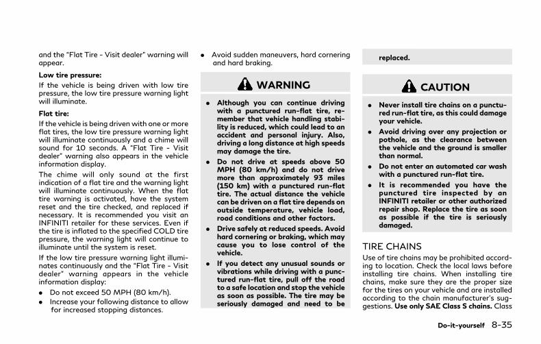
and the “Flat Tire - Visit dealer” warning willappear.
Low tire pressure:
If the vehicle is being driven with low tirepressure, the low tire pressure warning lightwill illuminate.
Flat tire:
If the vehicle is being drivenwith one or moreflat tires, the low tire pressure warning lightwill illuminate continuously and a chime willsound for 10 seconds. A “Flat Tire - Visitdealer” warning also appears in the vehicleinformation display.
The chime will only sound at the firstindication of a flat tire and the warning lightwill illuminate continuously. When the flattire warning is activated, have the systemreset and the tire checked, and replaced ifnecessary. It is recommended you visit anINFINITI retailer for these services. Even ifthe tire is inflated to the specified COLD tirepressure, the warning light will continue toilluminate until the system is reset.
If the low tire pressure warning light illumi-nates continuously and the “Flat Tire - Visitdealer” warning appears in the vehicleinformation display:
. Do not exceed 50 MPH (80 km/h).
. Increase your following distance to allowfor increased stopping distances.
. Avoid sudden maneuvers, hard corneringand hard braking.
WARNING
. Although you can continue drivingwith a punctured run-flat tire, re-member that vehicle handling stabi-lity is reduced, which could lead to anaccident and personal injury. Also,driving a long distance at high speedsmay damage the tire.
. Do not drive at speeds above 50MPH (80 km/h) and do not drivemore than approximately 93 miles(150 km) with a punctured run-flattire. The actual distance the vehiclecan be driven on a flat tire depends onoutside temperature, vehicle load,road conditions and other factors.
. Drive safely at reduced speeds. Avoidhard cornering or braking, which maycause you to lose control of thevehicle.
. If you detect any unusual sounds orvibrations while driving with a punc-tured run-flat tire, pull off the roadto a safe location and stop the vehicleas soon as possible. The tire may beseriously damaged and need to be
replaced.
CAUTION
. Never install tire chains on a punctu-red run-flat tire, as this could damageyour vehicle.
. Avoid driving over any projection orpothole, as the clearance betweenthe vehicle and the ground is smallerthan normal.
. Do not enter an automated car washwith a punctured run-flat tire.
. It is recommended you have thepunctured tire inspected by anINFINITI retailer or other authorizedrepair shop. Replace the tire as soonas possible if the tire is seriouslydamaged.
TIRE CHAINSUse of tire chains may be prohibited accord-ing to location. Check the local laws beforeinstalling tire chains. When installing tirechains, make sure they are the proper sizefor the tires on your vehicle and are installedaccording to the chain manufacturer’s sug-gestions. Use only SAE Class S chains. Class
Do-it-yourself 8-35

8-36 Do-it-yourself
“S” chains are used on vehicles with re-stricted tire to vehicle clearance. Vehiclesthat can use Class “S” chains are designed tomeet the SAE standard minimum clearancesbetween the tire and the closest vehiclesuspension or body component required toaccommodate the use of a winter tractiondevice (tire chains or cables). The minimumclearances are determined using the factoryequipped tire size. Other types may damageyour vehicle. Use chain tensioners whenrecommended by the tire chain manufac-turer to ensure a tight fit. Loose end links ofthe tire chain must be secured or removed toprevent the possibility of whipping actiondamage to the fenders or underbody. Ifpossible, avoid fully loading your vehiclewhen using tire chains. In addition, drive ata reduced speed. Otherwise, your vehiclemay be damaged and/or vehicle handlingand performance may be adversely affected.
Tire chains must be installed only on therear wheels and not on the front wheels.
Never install tire chains on a punctured run-flat tire, as this could damage your vehicle.
Do not use tire chains on dry roads. Drivingwith tire chains in such conditions can causedamage to the various mechanisms of thevehicle due to some overstress.
SDI1662
CHANGING WHEELS AND TIRES
Tire rotation
INFINITI recommends rotating thetires every 5,000 miles (8,000 km).(See “Jacking up the vehicle andreplacing tires” (P.8-39) for tire repla-cing procedures.)
As soon as possible, tighten thewheel nuts to the specified torquewith a torque wrench.
Wheel nut tightening torque:80 ft-lb (108 N·m)
The wheel nuts must be kept tigh-tened to the specification at all times.It is recommended that wheel nuts betightened to the specification at eachtire rotation interval.
WARNING
. After rotating the tires, checkand adjust the tire pressure.
. Retighten the wheel nuts whenthe vehicle has been driven for600 miles (1,000 km) (also incases of a flat tire, etc.).
. For additional information re-garding tires, refer to “Impor-tant Tire Safety Information”(US) or “Tire Safety Informa-tion” (Canada) in the WarrantyInformation Booklet.
After the ignition switch is placed inthe ON position, it may take a periodof time for the tire pressure to bedisplayed in the vehicle informationdisplay while the vehicle is driven.Depending on the radio wave circum-
stance, tire pressure may not cor-rectly be displayed.
SDI1663
: Wear indicator
: Wear indicator location mark. Thelocations are shown by “ ”, “TWI”,etc. depending on tire types.
Tire wear and damage
WARNING
. Tires should be periodically in-spected for wear, cracking, bul-ging or objects caught in thetread. If excessive wear, cracks,bulging or deep cuts are found,the tire(s) should be replaced.
. The original tires have built-intread wear indicators. Whenwear indicators are visible, thetire(s) should be replaced.
. Tires degrade with age and use.Have tires, including the spare,over 6 years old checked by aqualified technician, becausesome tire damage may not beobvious. Replace the tires asnecessary to prevent tire failureand possible personal injury.
. For additional information re-garding tires, refer to “Impor-tant Tire Safety Information”(US) or “Tire Safety Informa-tion” (Canada) in the WarrantyInformation Booklet.
Replacing wheels and tiresWhen replacing a tire, use the same size,tread design, speed rating and load carryingcapacity as originally equipped. (See “Speci-fications” (P.10-8) for recommended typesand sizes of tires and wheels.)
After the ignition switch is placed in the ONposition, it may take a period of time for the
Do-it-yourself 8-37

8-38 Do-it-yourself
tire pressure to be displayed in the vehicleinformation display while the vehicle isdriven. Depending on the radio wave circum-stance, tire pressure may not correctly bedisplayed.
WARNING
. The use of tires other than thoserecommended or the mixed use oftires of different brands, construc-tion (bias, bias-belted, radial or run-flat), or tread patterns can adverselyaffect the ride, braking, handling,ground clearance, body-to-tire clear-ance, tire chain clearance, speed-ometer calibration, headlight aimand bumper height. Some of theseeffects may lead to accidents andcould result in serious personal injury.
. For Two-Wheel Drive (2WD) models,if your vehicle was originallyequipped with 4 tires that were thesame size and you are only replacing2 of the 4 tires, install the new tireson the rear axle. Placing new tires onthe front axle may cause loss ofvehicle control in some driving condi-tions and cause an accident andpersonal injury.
. If the wheels are changed for anyreason, always replace with wheelswhich have the same off-set dimen-sion. Wheels of a different off-setcould cause premature tire wear,degrade vehicle handling character-istics and/or interference with thebrake discs/drums. Such interferencecan lead to decreased braking effi-ciency and/or early brake pad/shoewear. See “Wheels and tires” (P.10-9) of this manual for wheel off-setdimensions.
. When a wheel is replaced, the TPMSwill not function and the low tirepressure warning light will flash forapproximately 1 minute. The light willremain on after 1 minute. Have yourtires replaced and/or TPMS systemreset as soon as possible. It is recom-mended you visit an INFINITI retailerfor these services.
. Replacing tires with those not origin-ally specified by INFINITI could affectthe proper operation of the TPMS.
. The TPMS sensor may be damaged ifit is not handled correctly. Be carefulwhen handling the TPMS sensor.
. When replacing the TPMS sensor, theID registration may be required. It isrecommended you contact an
INFINITI retailer for ID registration.
. Do not use a valve stem cap that isnot specified by INFINITI. The valvestem cap may become stuck.
. Be sure that the valve stem caps arecorrectly fitted. Otherwise the valvemay be clogged up with dirt andcause a malfunction or loss of pres-sure.
. Do not install a damaged or deformedwheel or tire even if it has beenrepaired. Such wheels or tires couldhave structural damage and could failwithout warning.
. The use of retread tire is not recom-mended.
. For additional information regardingtires, refer to “Important Tire SafetyInformation” (US) or “Tire SafetyInformation” (Canada) in the War-ranty Information Booklet.

Intelligent All-Wheel Drive (AWD)models
CAUTION
Always use tires of the same type, size,brand, construction (bias, bias-belted orradial), and tread pattern on all fourwheels. Failure to do so may result in acircumference difference between tireson the front and rear axles which willcause excessive tire wear and maydamage the transmission, transfer caseand differential gears.
If excessive tire wear is found, it is recom-mended that all four tires be replaced withtires of the same size, brand, constructionand tread pattern. The tire pressure andwheel alignment should also be checked andcorrected as necessary. It is recommendedyou visit an INFINITI retailer for this service.
Wheel balanceUnbalancedwheels may affect vehicle hand-ling and tire life. Even with regular use,wheels can get out of balance. Therefore,they should be balanced as required.
Wheel balance service should be performedwith the wheels off the vehicle. Spinbalancing the wheels on the vehicle couldlead to mechanical damage.
For additional information regarding tires,refer to “Important Tire Safety Information”(US) or “Tire Safety Information” (Canada) inthe INFINITI Warranty Information Booklet.
Care of wheelsSee “Cleaning exterior” (P.7-2) for detailsabout care of the wheels.
JACKING UP THE VEHICLE ANDREPLACING TIRESYour vehicle is equipped with run-flat tiresand you can continue driving to a safelocation even if they are punctured. (See“Run-flat tires” (P.6-4) and “Run-flat tires”(P.8-34).)
This section contains the information aboutthe vehicle jack-up procedures and the tirereplacement.
NOTE:
Jacking tools are not equipped as standardwith this vehicle. Contact an INFINITIretailer about acquiring the tools.
WARNING
. Make sure the parking brake issecurely applied and the transmissioninto the P (Park) position.
. Never change tires when the vehicleis on a slope, ice or slippery areas.This is hazardous.
. Never change tires if oncoming traf-fic is close to your vehicle. Wait forprofessional road assistance.
Do-it-yourself 8-39

8-40 Do-it-yourself
MCE0001A
Blocking wheelsPlace suitable blocks at both the front andback of the wheel diagonally opposite theflat tire to prevent the vehicle from movingwhen it is jacked up.
WARNING
Be sure to block the wheel as the vehiclemay move and result in personal injury.
Jacking up the vehicle and removinga tire
WARNING
. Never get under the vehicle while it issupported only by the jack. If it isnecessary to work under the vehicle,support it with safety stands.
. Use the correct jack-up points. Neveruse any other part of the vehicle forjack support.
. Never jack up the vehicle more thannecessary.
. Never use blocks on or under the jack.
. Do not start or run the INFINITIDirect Response Hybrid® Systemwhile vehicle is on the jack, as it maycause the vehicle to move. This isespecially true for vehicles with lim-ited slip differentials.
. Do not allow passengers to stay inthe vehicle while it is on the jack.
Carefully read the caution label attached tothe jack body and the following instruc-tions.
CE1089-A
Jack-up point1. Place the jack directly under the jack-up
point as illustrated so the top of the jackcontacts the vehicle at the jack-up point.Align the jack head between the twonotches in the front or the rear as shown.Also fit the groove of the jack headbetween the notches as shown.
The jack should be used on level firmground.
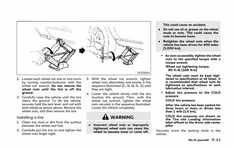
SCE0504
2. Loosen each wheel nut one or two turnsby turning counterclockwise with thewheel nut wrench. Do not remove thewheel nuts until the tire is off theground.
3. Carefully raise the vehicle until the tireclears the ground. To lift the vehicle,securely hold the jack lever and rod withboth hands as shown above. Remove thewheel nuts, and then remove the tire.
Installing a tire1. Clean any mud or dirt from the surface
between the wheel and hub.
2. Carefully put the tire on and tighten thewheel nuts finger tight.
3. With the wheel nut wrench, tightenwheel nuts alternately and evenly in thesequence illustrated ( , , , , ) untilthey are tight.
4. Lower the vehicle slowly until the tiretouches the ground. Then, with thewheel nut wrench, tighten the wheelnuts securely in the sequence illustrated.Lower the vehicle completely.
WARNING
. Incorrect wheel nuts or improperlytightened wheel nuts can cause thewheel to become loose or come off.
This could cause an accident.
. Do not use oil or grease on the wheelstuds or nuts. This could cause thenuts to become loose.
. Retighten the wheel nuts when thevehicle has been driven for 600 miles(1,000 km).
. As soon as possible, tighten the wheelnuts to the specified torque with atorque wrench.Wheel nut tightening torque:80 ft-lb (108 N·m)
The wheel nuts must be kept tigh-tened to specification at all times. Itis recommended that wheel nuts betightened to specifications at eachlubrication interval.
. Adjust tire pressure to the COLDpressure.
COLD tire pressure:
After the vehicle has been parked forthree hours or more or driven lessthan 1 mile (1.6 km).
COLD tire pressures are shown onthe Tire and Loading Informationlabel affixed to the driver side centerpillar.
Securely store the jacking tools in thevehicle.
Do-it-yourself 8-41

8-42 Do-it-yourself
MEMO
9 Maintenance and schedules
Maintenance requirement ............................................... 9-2
General maintenance .................................................. 9-2
Scheduled maintenance ............................................. 9-2
Where to go for service ............................................. 9-2
General maintenance........................................................ 9-2
Explanation of general maintenance items .......... 9-2
Explanation of scheduled maintenance items........... 9-5
Emission control system maintenance................... 9-5
Chassis and body maintenance ............................... 9-6
Maintenance schedules................................................... 9-6
Additional maintenance items for severeoperating conditions ................................................. 9-6
Standard maintenance ..................................................... 9-7
Emission control system maintenance ................ 9-8
Chassis and body maintenance ........................... 9-11
Maintenance under severe driving conditions........ 9-13
HEV Li-ion battery replacement record .................. 9-14
Maintenance log ............................................................. 9-16

9-2 Maintenance and schedules
Some day-to-day and regular maintenanceis essential to maintain your vehicle in goodmechanical condition, as well as its emissionand engine performance.
It is the owner’s responsibility to make surethat the scheduled maintenance, as well asgeneral maintenance, is performed.
As the vehicle owner, you are the only onewho can ensure that your vehicle receivesthe proper maintenance. You are a vital linkin the maintenance chain.
GENERAL MAINTENANCEGeneral maintenance includes those itemswhich should be checked during normal day-to-day operation. They are essential forproper vehicle operation. It is your respon-sibility to perform these procedures regularlyas prescribed.
Performing general maintenance checks re-quires minimal mechanical skill and only afew general automotive tools.
These checks or inspections can be done byyourself, a qualified technician or, if youprefer, an INFINITI retailer.
SCHEDULED MAINTENANCEThe maintenance items listed in this sectionare required to be serviced at regular inter-vals. However, under severe driving condi-t ions, addit ional or more frequentmaintenance will be required.
WHERE TO GO FOR SERVICEIf maintenance service is required or yourvehicle appears to malfunction, have thesystems checked and serviced. It is recom-mended you visit an INFINITI retailer for thisservice.
INFINITI technicians are well-trained spe-cialists and are kept up to date with thelatest service information through technicalbulletins, service tips and training programs.They are completely qualified to work onINFINITI vehicles before work begins.
You can be confident that an INFINITIretailer’s service department can performthe service needed to meet the maintenancerequirements on your vehicle.
During the normal day-to-day operation ofthe vehicle, general maintenance should beperformed regularly as prescribed in thissection. If you detect any unusual sounds,vibrations or smells, be sure to check for thecause and have it checked promptly. Inaddition, it is recommended you visit anINFINITI retailer if you think that repairs arerequired.
When performing any checks or mainte-nance work, closely observe “Maintenanceprecautions” (P.8-2) of this manual.
EXPLANATION OF GENERALMAINTENANCE ITEMSAdditional information on the followingitems with “*” is found in the “8. Do-it-yourself” section of this manual.
Outside the vehicleThe maintenance items listed here should beperformed from time to time, unless other-wise specified.
Doors and engine hood: Check that all doorsand the engine hood, operate properly. Alsoensure that all latches lock securely. Lubri-cate hinges, latches, latch pins, rollers andlinks if necessary. Make sure that thesecondary latch keeps the hood from open-ing when the primary latch is released.
When driving in areas using road salt or
MAINTENANCE REQUIREMENT GENERAL MAINTENANCE
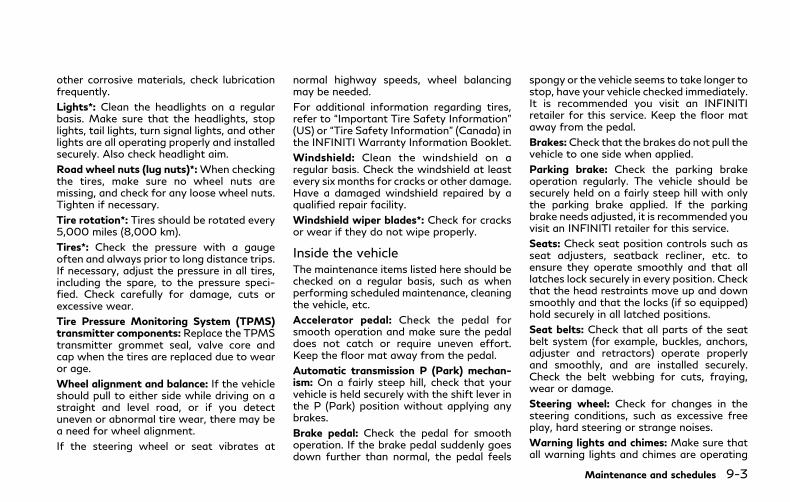
other corrosive materials, check lubricationfrequently.
Lights*: Clean the headlights on a regularbasis. Make sure that the headlights, stoplights, tail lights, turn signal lights, and otherlights are all operating properly and installedsecurely. Also check headlight aim.
Road wheel nuts (lug nuts)*:When checkingthe tires, make sure no wheel nuts aremissing, and check for any loose wheel nuts.Tighten if necessary.
Tire rotation*: Tires should be rotated every5,000 miles (8,000 km).
Tires*: Check the pressure with a gaugeoften and always prior to long distance trips.If necessary, adjust the pressure in all tires,including the spare, to the pressure speci-fied. Check carefully for damage, cuts orexcessive wear.
Tire Pressure Monitoring System (TPMS)transmitter components: Replace the TPMStransmitter grommet seal, valve core andcap when the tires are replaced due to wearor age.
Wheel alignment and balance: If the vehicleshould pull to either side while driving on astraight and level road, or if you detectuneven or abnormal tire wear, there may bea need for wheel alignment.
If the steering wheel or seat vibrates at
normal highway speeds, wheel balancingmay be needed.
For additional information regarding tires,refer to “Important Tire Safety Information”(US) or “Tire Safety Information” (Canada) inthe INFINITI Warranty Information Booklet.
Windshield: Clean the windshield on aregular basis. Check the windshield at leastevery six months for cracks or other damage.Have a damaged windshield repaired by aqualified repair facility.
Windshield wiper blades*: Check for cracksor wear if they do not wipe properly.
Inside the vehicleThe maintenance items listed here should bechecked on a regular basis, such as whenperforming scheduled maintenance, cleaningthe vehicle, etc.
Accelerator pedal: Check the pedal forsmooth operation and make sure the pedaldoes not catch or require uneven effort.Keep the floor mat away from the pedal.
Automatic transmission P (Park) mechan-ism: On a fairly steep hill, check that yourvehicle is held securely with the shift lever inthe P (Park) position without applying anybrakes.
Brake pedal: Check the pedal for smoothoperation. If the brake pedal suddenly goesdown further than normal, the pedal feels
spongy or the vehicle seems to take longer tostop, have your vehicle checked immediately.It is recommended you visit an INFINITIretailer for this service. Keep the floor mataway from the pedal.
Brakes:Check that the brakes do not pull thevehicle to one side when applied.
Parking brake: Check the parking brakeoperation regularly. The vehicle should besecurely held on a fairly steep hill with onlythe parking brake applied. If the parkingbrake needs adjusted, it is recommended youvisit an INFINITI retailer for this service.
Seats: Check seat position controls such asseat adjusters, seatback recliner, etc. toensure they operate smoothly and that alllatches lock securely in every position. Checkthat the head restraints move up and downsmoothly and that the locks (if so equipped)hold securely in all latched positions.
Seat belts: Check that all parts of the seatbelt system (for example, buckles, anchors,adjuster and retractors) operate properlyand smoothly, and are installed securely.Check the belt webbing for cuts, fraying,wear or damage.
Steering wheel: Check for changes in thesteering conditions, such as excessive freeplay, hard steering or strange noises.
Warning lights and chimes: Make sure thatall warning lights and chimes are operating
Maintenance and schedules 9-3
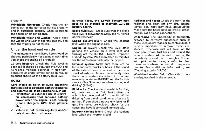
9-4 Maintenance and schedules
properly.
Windshield defroster: Check that the aircomes out of the defroster outlets properlyand in sufficient quantity when operatingthe heater or air conditioner.
Windshield wiper and washer*: Check thatthe wipers and washer operate properly andthat the wipers do not streak.
Under the hood and vehicleThe maintenance items listed here should bechecked periodically (for example, each timeyou check the engine oil or refuel).
12-volt battery*: Check the fluid level ineach cell. It should be between the MAX andMIN lines. Vehicles operated in high tem-peratures or under severe condition requirefrequent checks of the battery fluid level.
NOTE:
Care should be taken to avoid situationsthat can lead to potential battery dischargeand potential no-start conditions such as:1. Installation or extended use of electro-
nic accessories that consume batterypower when the engine is not running(Phone chargers, GPS, DVD players,etc.)
2. Vehicle is not driven regularly and/oronly driven short distances.
In these cases, the 12-volt battery mayneed to be charged to maintain 12-voltbattery health.
Brake fluid level*:Make sure that the brakefluid level is between theMAX andMIN lineson the reservoir.
Engine coolant level*: Check the coolantlevel when the engine is cold.
Engine oil level*: Check the level afterparking the vehicle on a level spot andturning off the INFINITI Direct ResponseHybrid® System. Wait more than 15 minutesfor the oil to drain back into the oil pan.
Exhaust system: Make sure there are noloose supports, cracks or holes. If the soundof the exhaust seems unusual or there is asmell of exhaust fumes, immediately havethe exhaust system inspected. It is recom-mended you visit an INFINITI retailer for thisservice. (See “Precautions when starting anddriving” (P.5-4).)
Fluid leaks: Check under the vehicle for fuel,oil, water or other fluid leaks after thevehicle has been parked for a while. Waterdripping from the air conditioner after use isnormal. If you should notice any leaks or ifgasoline fumes are evident, check for thecause and have it corrected immediately.
Inverter coolant level*: Check the coolantlevel when the inverter is cold.
Radiator and hoses: Check the front of theradiator and clean off any dirt, insects,leaves, etc., that may have accumulated.Make sure the hoses have no cracks, defor-mation, rot or loose connections.
Underbody: The underbody is frequentlyexposed to corrosive substances such asthose used on icy roads or to control dust. Itis very important to remove these sub-stances, otherwise rust will form on thefloor pan, frame, fuel lines and around theexhaust system. At the end of winter, theunderbody should be thoroughly flushedwith plain water, being careful to cleanthose areas where mud and dirt may accu-mulate. For additional information, see“Cleaning exterior” (P.7-2).
Windshield washer fluid*: Check that thereis adequate fluid in the reservoir.

The following descriptions are provided togive you a better understanding of thescheduled maintenance items that shouldbe regularly checked or replaced. The main-tenance schedule indicates at which mile-age/time intervals each item requiresservice.
In addition to scheduled maintenance, yourvehicle requires that some items be checkedduring normal day-to-day operation. Referto “General maintenance” (P.9-2).
Items marked with “*” are recommended byINFINITI for reliable vehicle operation. Youare not required to perform maintenance onthese items in order to maintain the warran-ties which come with your vehicle. Othermaintenance items and intervals are re-quired.
When applicable, additional information canbe found in the “8. Do-it-yourself” section ofthis manual.
NOTE:
INFINITI does not advocate the use of non-OEM approved aftermarket flushing sys-tems and strongly advises against perform-ing these services on an INFINITI product.Many of the aftermarket flushing systemsuse non-OEM approved chemicals or sol-vents, the use of which has not beenvalidated by INFINITI.
For recommended fuel, lubricants, fluids,grease, and refrigerant, refer to “Capacitiesand recommended fluids/lubricants” (P.10-2) of this manual.
EMISSION CONTROL SYSTEMMAINTENANCEEngine air filter:
Replace at specified intervals. When drivingfor prolonged periods in dusty conditions,check/replace the filter more frequently.
Engine coolant*:
Replace coolant at the specified interval.When adding or replacing coolant, be sure touse only Genuine NISSAN Long Life Anti-freeze/Coolant (blue) or equivalent with theproper mixture. (Refer to “Engine coolingsystem” (P.8-5) to determine the propermixture for your area.)
NOTE:
Mixing any other type of coolant or the useof non-distilled water may reduce therecommended service interval of the cool-ant.
Hybrid Electronic Vehicle (HEV) invertercoolant:
Replace inverter coolant at the specifiedinterval. When adding or replacing coolant,be sure to use only Genuine NISSAN LongLife Antifreeze/Coolant (blue) or equivalent
with the proper mixture. (Refer to “Invertercooling system” (P.8-7) to determine theproper mixture for your area.)
NOTE:
Mixing any other type of coolant or the useof non-distilled water may reduce therecommended service interval of the cool-ant.
Engine oil and oil filter:
Replace engine oil and oil filter at thespecified intervals. For recommended oilgrade and viscosity refer to “Capacities andrecommended fluids/lubricants” (P.10-2).
Engine valve clearance*:
Inspect only if valve noise increases. Adjustvalve clearance if necessary.
Evaporative emissions control vapor lines*:
Check vapor lines for leaks or looseness.Tighten connections or replace parts asnecessary.
Fuel lines*:
Check the fuel hoses, piping and connectionsfor leaks, looseness, or deterioration. Tight-en connections or replace parts as necessary.
Spark plugs:
Replace at specified intervals. Install newplugs of the type as originally equipped.
Maintenance and schedules 9-5
EXPLANATION OF SCHEDULEDMAINTENANCE ITEMS

9-6 Maintenance and schedules
CHASSIS AND BODY MAINTE-NANCEBrake lines and cables:
Visually inspect for proper installation.Check for chafing, cracks, deterioration,and signs of leaking. Replace any deterio-rated or damaged parts immediately.
Brake pads, rotors, drums and linings:
Check for wear, deterioration and fluidleaks. Replace any deteriorated or damagedparts immediately.
Exhaust system:
Visually inspect the exhaust pipes, mufflerand hangers for leaks, cracks, deterioration,and damage. Tighten connections or replaceparts as necessary.
In-cabin microfilter:
Replace at specified intervals. When drivingfor prolonged periods in dusty conditions,replace the filter more frequently.
Propeller shaft(s):
Check for damage, looseness, and greaseleakage. (4WD/AWD/RWD)
Steering gear and linkage, axle and suspen-sion parts, drive shaft boots:
Check for damage, looseness, and leakageof oil or grease. Under severe driving condi-tions, inspect more frequently.
Tire rotation:
Tires should be rotated every 5,000 miles(8,000 km) according to the instructionsunder “Explanation of general maintenanceitems” (P.9-2).When rotating tires, check fordamage and uneven wear. Replace if neces-sary.
Transmission fluid/oil, differential oil andtransfer case oil:
Visually inspect for signs of leakage atspecified intervals.
To help ensure smooth, safe and economicaldriving, INFINITI provides two maintenanceschedules that may be used, depending uponthe conditions in which you usually drive.These schedules contain both distance andtime intervals, up to 120,000 miles(192,000 km)/144 months. For most peo-ple, the odometer reading will indicate whenservice is needed. However, if you drive verylittle, your vehicle should be serviced at theregular time intervals shown in the schedule.
After 120,000 miles (192,000 km)/144months, continue maintenance at the samemileage/time intervals.
ADDITIONAL MAINTENANCEITEMS FOR SEVERE OPERATINGCONDITIONSAdditional maintenance items for severeoperating conditions should be performedon vehicles that are driven under especiallydemanding conditions. Additional mainte-nance items should be performed if youprimarily operate your vehicle under thefollowing conditions:
. Repeated short trips of less than 5 miles(8 km).
. Repeated short trips of less than 10miles(16 km) with outside temperatures re-maining below freezing.
MAINTENANCE SCHEDULES
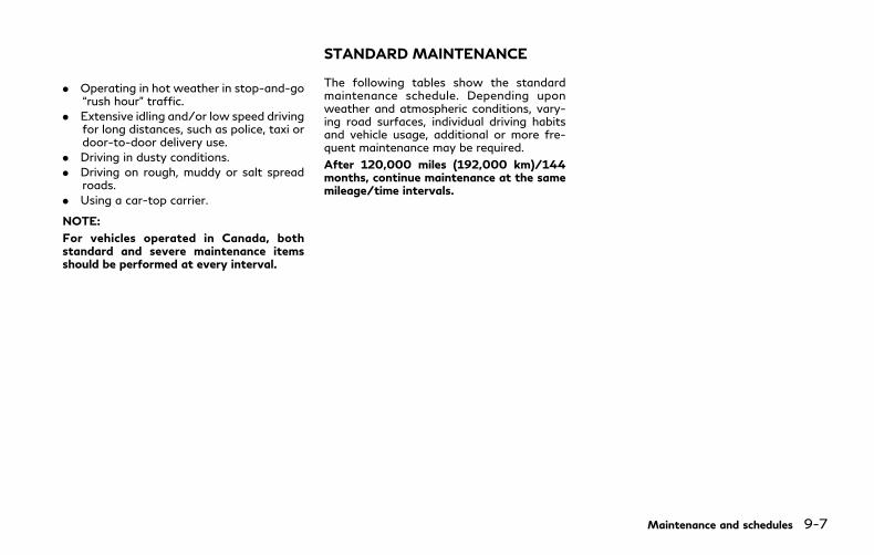
. Operating in hot weather in stop-and-go“rush hour” traffic.
. Extensive idling and/or low speed drivingfor long distances, such as police, taxi ordoor-to-door delivery use.
. Driving in dusty conditions.
. Driving on rough, muddy or salt spreadroads.
. Using a car-top carrier.
NOTE:
For vehicles operated in Canada, bothstandard and severe maintenance itemsshould be performed at every interval.
The following tables show the standardmaintenance schedule. Depending uponweather and atmospheric conditions, vary-ing road surfaces, individual driving habitsand vehicle usage, additional or more fre-quent maintenance may be required.
After 120,000 miles (192,000 km)/144months, continue maintenance at the samemileage/time intervals.
Maintenance and schedules 9-7
STANDARD MAINTENANCE
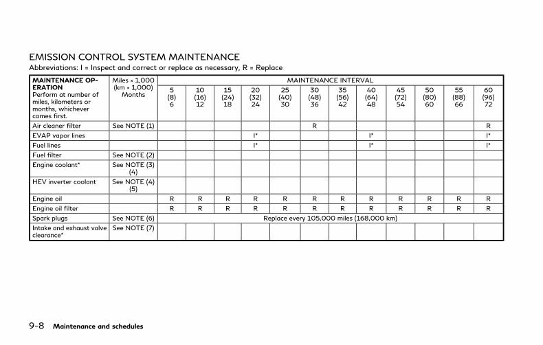
9-8 Maintenance and schedules
EMISSION CONTROL SYSTEM MAINTENANCEAbbreviations: I = Inspect and correct or replace as necessary, R = Replace
MAINTENANCE OP-ERATIONPerform at number ofmiles, kilometers ormonths, whichevercomes first.
Miles × 1,000(km × 1,000)Months
MAINTENANCE INTERVAL
5(8)6
10(16)12
15(24)18
20(32)24
25(40)30
30(48)36
35(56)42
40(64)48
45(72)54
50(80)60
55(88)66
60(96)72
Air cleaner filter See NOTE (1) R R
EVAP vapor lines I* I* I*
Fuel lines I* I* I*
Fuel filter See NOTE (2)
Engine coolant* See NOTE (3)(4)
HEV inverter coolant See NOTE (4)(5)
Engine oil R R R R R R R R R R R R
Engine oil filter R R R R R R R R R R R R
Spark plugs See NOTE (6) Replace every 105,000 miles (168,000 km)
Intake and exhaust valveclearance*
See NOTE (7)

MAINTENANCE OP-ERATIONPerform at number ofmiles, kilometers ormonths, whichevercomes first.
Miles × 1,000(km × 1,000)Months
MAINTENANCE INTERVAL
65(104)78
70(112)84
75(120)90
80(128)96
85(136)102
90(144)108
95(152)114
100(160)120
105(168)126
110(176)132
115(184)138
120(192)144
Air cleaner filter See NOTE (1) R R
EVAP vapor lines I* I* I*
Fuel lines I* I* I*
Fuel filter See NOTE (2)
Engine coolant* See NOTE (3)(4)
HEV inverter coolant See NOTE (4)(5)
Engine oil R R R R R R R R R R R R
Engine oil filter R R R R R R R R R R R R
Spark plugs See NOTE (6) Replace every 105,000 miles (168,000 km)
Intake and exhaust valveclearance*
See NOTE (7)
NOTE:
(1) If operating mainly in dusty conditions,more frequent maintenance may be re-quired.
(2) Periodic maintenance is not required.
(3) First replacement interval is 105,000miles (168,000 km) or 84 months. Afterfirst replacement, replace every 75,000miles (120,000 km) or 60 months.
(4) Use only Genuine NISSAN Long Life
Antifreeze/Coolant (blue) or equivalentwith proper mixture ratio of 50% anti-freeze and 50% demineralized or distilledwater. Mixing any other type of coolant orthe use of non-distilled water may reducethe life expectancy of the factory fill cool-ant.
(5) First replacement interval is 12,5000miles (200,000 km) or 180 months. Afterfirst replacement, replace every 75,000miles (120,000 km) or 60 months.
(6) Replace spark plug when the plug gapexceeds 0.055 in (1.4 mm) even if withinspecified replacement mileage.
(7) Periodic maintenance is not required.However, if valve noise increases, inspectvalve clearance.
*: Maintenance items and intervals with “*”are recommended by INFINITI for reliablevehicle operation. The owner need not toperform such maintenance in order tomaintain the emission warranty or manu-
Maintenance and schedules 9-9

9-10 Maintenance and schedules
facturer recall liability. Other maintenanceitems and intervals are required.
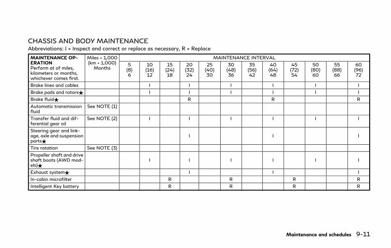
CHASSIS AND BODY MAINTENANCEAbbreviations: I = Inspect and correct or replace as necessary, R = Replace
MAINTENANCE OP-ERATIONPerform at of miles,kilometers or months,whichever comes first.
Miles × 1,000(km × 1,000)Months
MAINTENANCE INTERVAL
5(8)6
10(16)12
15(24)18
20(32)24
25(40)30
30(48)36
35(56)42
40(64)48
45(72)54
50(80)60
55(88)66
60(96)72
Brake lines and cables I I I I I I
Brake pads and rotors$ I I I I I I
Brake fluid$ R R R
Automatic transmissionfluid
See NOTE (1)
Transfer fluid and dif-ferential gear oil
See NOTE (2) I I I I I I
Steering gear and link-age, axle and suspensionparts$
I I I
Tire rotation See NOTE (3)
Propeller shaft and driveshaft boots (AWD mod-els)$
I I I I I I
Exhaust system$ I I I
In-cabin microfilter R R R R
Intelligent Key battery R R R R
Maintenance and schedules 9-11

9-12 Maintenance and schedules
MAINTENANCE OP-ERATIONPerform at of miles, kilo-meters or months,whichever comes first.
Miles × 1,000(km × 1,000)Months
MAINTENANCE INTERVAL
65(104)78
70(112)84
75(120)90
80(128)96
85(136)102
90(144)108
95(152)114
100(160)120
105(168)126
110(176)132
115(184)138
120(192)144
Brake lines & cables I I I I I I
Brake pads & rotors$ I I I I I I
Brake fluid$ R R R
Automatic transmissionfluid
See NOTE (1)
Transfer fluid & differen-tial gear oil
See NOTE (2) I I I I I I
Steering gear & linkage,axle & suspension parts$
I I I
Tire rotation See NOTE (3)
Propeller shaft & driveshaft boots (AWD mod-els)$
I I I I I I
Exhaust system$ I I I
In-cabin microfilter R R R R
Intelligent Key battery R R R R
NOTE:
Maintenance items with “$” should beperformed more frequently according to“Maintenance under severe driving condi-tions” (P.9-13).
(1) Periodic maintenance is not required.
(2) If using a car-top carrier, or driving onrough or muddy roads, change (not just
inspect) oil at every 20,000 miles (32,000km) or 24 months.
(3) Refer to “Tire rotation” under “Generalmaintenance” (P.9-2).

The maintenance intervals shown on thepreceding pages are for normal operatingconditions. If the vehicle is mainly operatedunder severe driving conditions as shownbelow, more frequent maintenance must beperformed on the following items as shownin the table.
Severe driving conditions
. Repeated short trips of less than 5 miles(8 km).
. Repeated short trips of less than 10miles(16 km) with outside temperatures re-maining below freezing.
. Operating in hot weather in stop-and-go“rush hour” traffic.
. Extensive idling and/or low speed drivingfor long distances, such as police, taxi ordoor-to-door delivery use.
. Driving in dusty conditions.
. Driving on rough, muddy, or salt spreadroads.
. Using a car-top carrier.
Maintenance operation: Inspect = Inspectand correct or replace as necessary.
Maintenance item Maintenance operation Maintenance interval
Brake fluid Replace Every 10,000 miles (16,000 km) or 12months
Brake pads & rotors Inspect Every 5,000 miles (8,000 km) or 6months
Steering gear & linkage, axle &suspension parts
Inspect Every 5,000 miles (8,000 km) or 6months
Propeller shaft & drive shaftboots (AWD models)
Inspect Every 5,000 miles (8,000 km) or 6months
Exhaust system Inspect Every 5,000 miles (8,000 km) or 6months
Maintenance and schedules 9-13
MAINTENANCE UNDER SEVEREDRIVING CONDITIONS
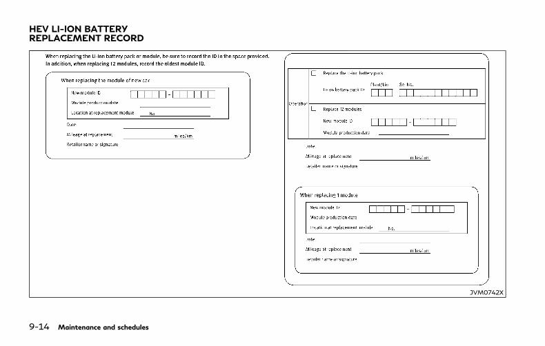
9-14 Maintenance and schedules
JVM0742X
HEV LI-ION BATTERYREPLACEMENT RECORD
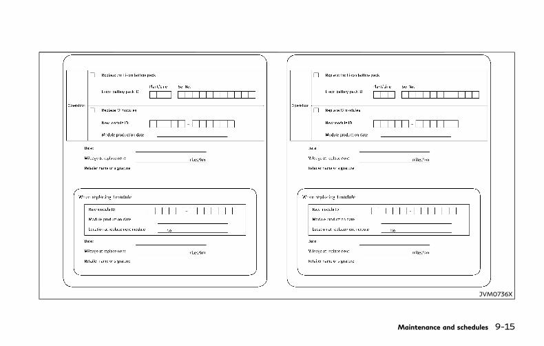
JVM0736X
Maintenance and schedules 9-15

9-16 Maintenance and schedules
5,000 Miles (8,000 km) or 6 Months
Retailer Name:
Date:
Mileage:
RetailerStamp:
10,000 Miles (16,000 km) or 12 Months
Retailer Name:
Date:
Mileage:
RetailerStamp:
15,000 Miles (24,000 km) or 18 Months
Retailer Name:
Date:
Mileage:
RetailerStamp:
20,000 Miles (32,000 km) or 24 Months
Retailer Name:
Date:
Mileage:
RetailerStamp:
25,000 Miles (40,000 km) or 30 Months
Retailer Name:
Date:
Mileage:
RetailerStamp:
30,000 Miles (48,000 km) or 36 Months
Retailer Name:
Date:
Mileage:
RetailerStamp:
35,000 Miles (56,000 km) or 42 Months
Retailer Name:
Date:
Mileage:
RetailerStamp:
40,000 Miles (64,000 km) or 48 Months
Retailer Name:
Date:
Mileage:
RetailerStamp:
45,000 Miles (72,000 km) or 54 Months
Retailer Name:
Date:
Mileage:
RetailerStamp:
MAINTENANCE LOG
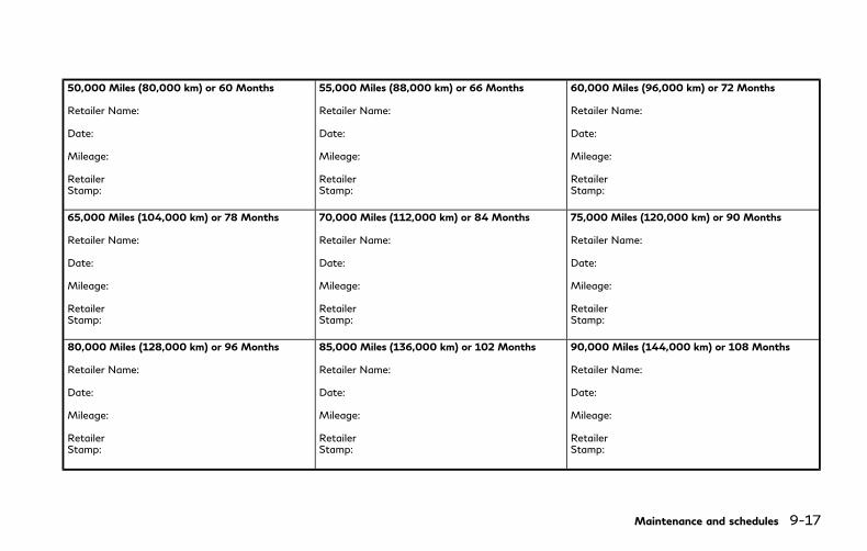
50,000 Miles (80,000 km) or 60 Months
Retailer Name:
Date:
Mileage:
RetailerStamp:
55,000 Miles (88,000 km) or 66 Months
Retailer Name:
Date:
Mileage:
RetailerStamp:
60,000 Miles (96,000 km) or 72 Months
Retailer Name:
Date:
Mileage:
RetailerStamp:
65,000 Miles (104,000 km) or 78 Months
Retailer Name:
Date:
Mileage:
RetailerStamp:
70,000 Miles (112,000 km) or 84 Months
Retailer Name:
Date:
Mileage:
RetailerStamp:
75,000 Miles (120,000 km) or 90 Months
Retailer Name:
Date:
Mileage:
RetailerStamp:
80,000 Miles (128,000 km) or 96 Months
Retailer Name:
Date:
Mileage:
RetailerStamp:
85,000 Miles (136,000 km) or 102 Months
Retailer Name:
Date:
Mileage:
RetailerStamp:
90,000 Miles (144,000 km) or 108 Months
Retailer Name:
Date:
Mileage:
RetailerStamp:
Maintenance and schedules 9-17

9-18 Maintenance and schedules
95,000 Miles (152,000 km) or 114 Months
Retailer Name:
Date:
Mileage:
RetailerStamp:
100,000 Miles (160,000 km) or 120 Months
Retailer Name:
Date:
Mileage:
RetailerStamp:
105,000 Miles (168,000 km) or 126 Months
Retailer Name:
Date:
Mileage:
RetailerStamp:
110,000 Miles (176,000 km) or 132 Months
Retailer Name:
Date:
Mileage:
RetailerStamp:
115,000 Miles (184,000 km) or 138 Months
Retailer Name:
Date:
Mileage:
RetailerStamp:
120,000 Miles (192,000 km) or 144 Months
Retailer Name:
Date:
Mileage:
RetailerStamp:

10 Technical and consumer information
Capacities and recommended fluids/lubricants ..... 10-2
Fuel information........................................................ 10-4
Engine oil and oil filter recommendation ............ 10-6
Air conditioning system refrigerant andlubricant recommendations..................................... 10-7
Specifications .................................................................. 10-8
Engine .......................................................................... 10-8
Wheels and tires ........................................................ 10-9
Dimensions................................................................... 10-9
When traveling or registering inanother country ............................................................ 10-10
Vehicle identification ................................................... 10-10
Vehicle Identification Number (VIN) plate....... 10-10
Vehicle identification number(chassis number) ...................................................... 10-10
Engine serial number .............................................. 10-11
F.M.V.S.S./C.M.V.S.S. certification label .......... 10-11
Emission control information label ..................... 10-11
Tire and loading information label ..................... 10-12
Air conditioner specification label ...................... 10-12
Installing front license plate ..................................... 10-13
Removing air deflectors ............................................. 10-14
Vehicle loading information ...................................... 10-15
Terms........................................................................ 10-15
Vehicle load capacity ........................................... 10-16
Loading tips............................................................. 10-17
Measurement of weights .................................... 10-17
Towing a trailer ............................................................ 10-18
Flat towing ............................................................. 10-18
Uniform tire quality grading ..................................... 10-18
Treadwear............................................................... 10-18
Traction AA, A, B and C ..................................... 10-19
Temperature A, B and C..................................... 10-19
Emission control system warranty ......................... 10-19
Reporting safety defects ........................................... 10-20
Readiness for Inspection/Maintenance (I/M)test (US only) ................................................................ 10-21
Event Data Recorders (EDR) ................................... 10-21
Owner’s Manual/Service Manualorder information......................................................... 10-22
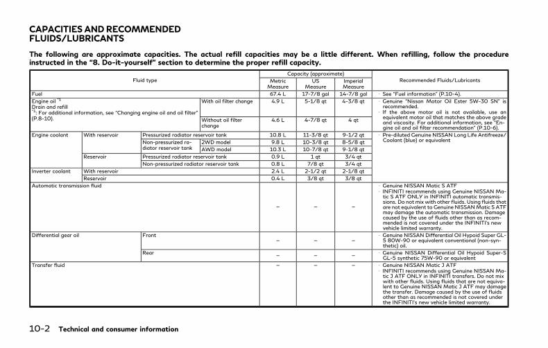
10-2 Technical and consumer information
The following are approximate capacities. The actual refill capacities may be a little different. When refilling, follow the procedureinstructed in the “8. Do-it-yourself” section to determine the proper refill capacity.
Fluid typeCapacity (approximate)
Recommended Fluids/LubricantsMetricMeasure
USMeasure
ImperialMeasure
Fuel 67.4 L 17-7/8 gal 14-7/8 gal See “Fuel information” (P.10-4).
Engine oil *1
Drain and refill*1: For additional information, see “Changing engine oil and oil filter”(P.8-10).
With oil filter change 4.9 L 5-1/8 qt 4-3/8 qt Genuine “Nissan Motor Oil Ester 5W-30 SN” isrecommended.If the above motor oil is not available, use anequivalent motor oil that matches the above gradeand viscosity. For additional information, see “En-gine oil and oil filter recommendation” (P.10-6).
Without oil filterchange
4.6 L 4-7/8 qt 4 qt
Engine coolant With reservoir Pressurized radiator reservoir tank 10.8 L 11-3/8 qt 9-1/2 qt Pre-diluted Genuine NISSAN Long Life Antifreeze/Coolant (blue) or equivalentNon-pressurized ra-
diator reservoir tank2WD model 9.8 L 10-3/8 qt 8-5/8 qt
AWD model 10.3 L 10-7/8 qt 9-1/8 qt
Reservoir Pressurized radiator reservoir tank 0.9 L 1 qt 3/4 qt
Non-pressurized radiator reservoir tank 0.8 L 7/8 qt 3/4 qt
Inverter coolant With reservoir 2.4 L 2-1/2 qt 2-1/8 qt
Reservoir 0.4 L 3/8 qt 3/8 qt
Automatic transmission fluid
— — —
Genuine NISSAN Matic S ATFINFINITI recommends using Genuine NISSAN Ma-tic S ATF ONLY in INFINITI automatic transmis-sions. Do not mix with other fluids. Using fluids thatare not equivalent to Genuine NISSANMatic S ATFmay damage the automatic transmission. Damagecaused by the use of fluids other than as recom-mended is not covered under the INFINITI’s newvehicle limited warranty.
Differential gear oil Front— — —
Genuine NISSAN Differential Oil Hypoid Super GL-5 80W-90 or equivalent conventional (non-syn-thetic) oil.
Rear — — — Genuine NISSAN Differential Oil Hypoid Super-SGL-5 synthetic 75W-90 or equivalent
Transfer fluid — — — Genuine NISSAN Matic J ATFINFINITI recommends using Genuine NISSAN Ma-tic J ATF ONLY in INFINITI transfers. Do not mixwith other fluids. Using fluids that are not equiva-lent to Genuine NISSAN Matic J ATF may damagethe transfer. Damage caused by the use of fluidsother than as recommended is not covered underthe INFINITI’s new vehicle limited warranty.
CAPACITIES ANDRECOMMENDEDFLUIDS/LUBRICANTS

Fluid typeCapacity (approximate)
Recommended Fluids/LubricantsMetricMeasure
USMeasure
ImperialMeasure
Brake fluidRefill to the proper oil level according to theinstructions in the “8. Do-it-yourself” section.
Genuine NISSAN Super Heavy Duty Brake Fluid*2
or equivalent DOT 3*2: Available in mainland U.S.A through an INFINITIretailer.
Multi-purpose grease — — — NLGI No. 2 (Lithium soap base)
Air conditioning system refrigerant
— — —
HFC-134a (R-134a)For additional information, see “Vehicle identifica-tion” (P.10-10) for air conditioner specificationlabel.
Air conditioning system lubricants — — — AE-10
Window washer fluid — — — Genuine NISSAN Windshield Washer ConcentrateCleaner & Antifreeze or equivalent
Technical and consumer information 10-3

10-4 Technical and consumer information
FUEL INFORMATIONUse unleaded premium gasoline with anoctane rating of at least 91 AKI (Anti-KnockIndex) number (Research octane number 96).
If unleaded premium gasoline is not avail-able, unleaded regular gasoline with anoctane rating of at least 87 AKI number(Research octane number 91) may be tem-porarily used, but only under the followingprecautions:
. Have the fuel tank filled only partiallywith unleaded regular gasoline, and fillup with unleaded premium gasoline assoon as possible.
. Avoid full throttle driving and abruptacceleration.
Use unleaded premium gasoline for max-imum vehicle performance.
CAUTION
. Using a fuel other than that specifiedcould adversely affect the emissioncontrol system, and may also affectwarranty coverage.
. Under no circumstances should aleaded gasoline be used, because thiswill damage the three-way catalyst.
. Do not use a fuel containing morethan 15% ethanol in your vehicle.Your vehicle is not designed to run ona fuel containing more than 15%ethanol. Using a fuel containing morethan 15% ethanol in a vehicle notspecifically designed for a fuel con-taining more than 15% ethanol canadversely affect the emission controldevices and systems of the vehicle.Damage caused by such fuel is notcovered by the INFINITI new vehiclelimited warranty.
. Do not use fuel that contains theoctane booster methylcyclopentadie-nyl manganese tricarbonyl (MMT).Using fuel containing MMT mayadversely affect vehicle performanceand vehicle emissions. Not all fueldispensers are labeled to indicateMMT content, so you may have toconsult your gasoline retailer formore details. Note that Federal andCalifornia laws prohibit the use ofMMT in reformulated gasoline.
. U.S. government regulations requireethanol dispensing pumps to be iden-tified by a small, square, orange andblack label with the common abbre-viation or the appropriate percen-tage for that region.
Gasoline specificationsINFINITI recommends using gasoline thatmeets the World-Wide Fuel Charter(WWFC) specifications where it is available.Many of the automobile manufacturersdeveloped this specification to improveemission system and vehicle performance.Ask your service station manager if thegasoline meets the World-Wide Fuel Char-ter (WWFC) specifications.
Reformulated gasolineSome fuel suppliers are now producingreformulated gasolines. These gasolines arespecially designed to reduce vehicle emis-sions. INFINITI supports efforts towardscleaner air and suggests that you usereformulated gasoline when available.
Gasoline containing oxygenatesSome fuel suppliers sell gasoline containingoxygenates such as ethanol, MTBE andmethanol with or without advertising theirpresence. INFINITI does not recommend theuse of fuels of which the oxygenate contentand the fuel compatibility for your INFINITIcannot be readily determined. If in doubt, askyour service station manager.
If you use oxygenate-blend gasoline, pleasetake the following precautions as the usageof such fuels may cause vehicle performance
problems and/or fuel system damage.
. The fuel should be unleaded and have anoctane rating no lower than that re-commended for unleaded gasoline.
. If an oxygenate-blend, excepting amethanol blend, is used, it should con-tain no more than 15% oxygenate.
. If a methanol blend is used, it shouldcontain no more than 5% methanol(methyl alcohol, wood alcohol). It shouldalso contain a suitable amount of ap-propriate cosolvents and corrosion in-hibitors. If not properly formulated withappropriate cosolvents and corrosioninhibitors, such methanol blends maycause fuel system damage and/or vehi-cle performance problems. At this time,sufficient data is not available to ensurethat all methanol blends are suitable foruse in INFINITI vehicles.
If any undesirable driveability problems suchas engine stalling or hard hot starting areexperienced after using oxygenate-blendfuels, immediately change to a non-oxyge-nate fuel or a fuel with a low blend ofMTBE.
Take care not to spill gasoline duringrefueling. Gasoline containing oxygenatescan cause paint damage.
E-15 fuelE-15 fuel is a mixture of approximately 15%fuel ethanol and 85% unleaded gasoline. E-15 can only be used in vehicles designed torun on E-15 fuel. U.S. government regula-tions require fuel ethanol dispensing pumpsto be identified with small, square, orangeand black label with the common abbrevia-tion or the appropriate percentage for thatregion.
E-85 fuelE-85 fuel is a mixture of approximately 85%fuel ethanol and 15% unleaded gasoline. E-85 can only be used in a Flexible Fuel Vehicle(FFV). Do not use E-85 fuel in your vehicle.U.S. government regulations require fuelethanol dispensing pumps to be identifiedby a small, square, orange and black labelwith the common abbreviation or the appro-priate percentage for that region.
Fuel containing MMTMMT, or methylcyclopentadienyl manga-nese tricarbonyl, is an octane boostingadditive. INFINITI does not recommend theuse of fuel containing MMT. Such fuel mayadversely affect vehicle performance, in-cluding the emissions control system. Notethat while some fuel pumps label MMTcontent, not all do, so you may have to
consult your gasoline retailer for more de-tails.
Aftermarket fuel additivesINFINITI does not recommend the use of anyaftermarket fuel additives (Example: fuelinjector cleaner, octane booster, intake valvedeposit removers, etc.) which are sold com-mercially. Many of these additives intendedfor gum, varnish or deposit removal maycontain active solvent or similar ingredientsthat can be harmful to the fuel system andengine.
Octane rating tipsUsing unleaded gasoline with an octanerating lower than recommended above cancause persistent, heavy spark knock. (Sparkknock is a metallic rapping noise.) If severe,this can lead to engine damage. If youdetect a persistent heavy spark knock evenwhen using gasoline of the stated octanerating, or if you hear steady spark knockwhile holding a steady speed on level roads,it is recommended you have an INFINITIretailer correct the condition. Failure tocorrect the condition is misuse of thevehicle, for which INFINITI is not respon-sible.
Incorrect ignition timing will result in knock-ing, after-run or overheating. This in turnmay cause excessive fuel consumption or
Technical and consumer information 10-5
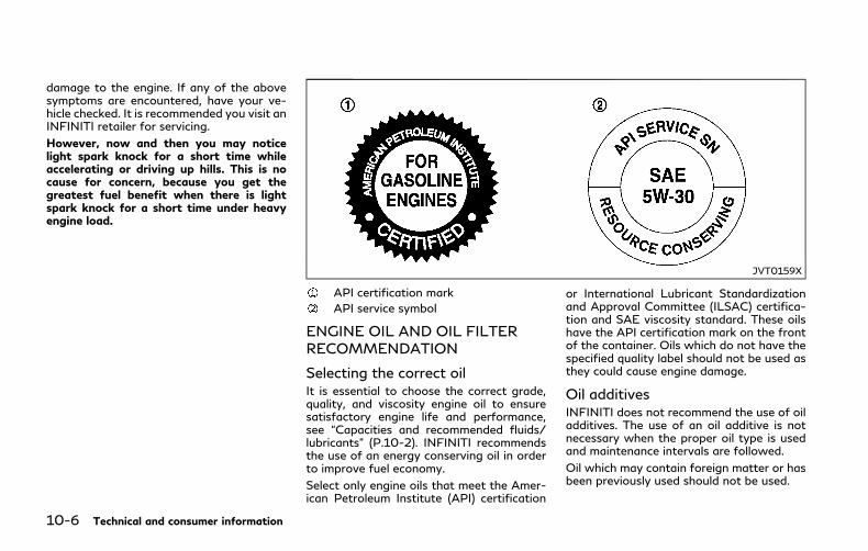
10-6 Technical and consumer information
damage to the engine. If any of the abovesymptoms are encountered, have your ve-hicle checked. It is recommended you visit anINFINITI retailer for servicing.
However, now and then you may noticelight spark knock for a short time whileaccelerating or driving up hills. This is nocause for concern, because you get thegreatest fuel benefit when there is lightspark knock for a short time under heavyengine load.
JVT0159X
API certification mark
API service symbol
ENGINE OIL AND OIL FILTERRECOMMENDATION
Selecting the correct oilIt is essential to choose the correct grade,quality, and viscosity engine oil to ensuresatisfactory engine life and performance,see “Capacities and recommended fluids/lubricants” (P.10-2). INFINITI recommendsthe use of an energy conserving oil in orderto improve fuel economy.
Select only engine oils that meet the Amer-ican Petroleum Institute (API) certification
or International Lubricant Standardizationand Approval Committee (ILSAC) certifica-tion and SAE viscosity standard. These oilshave the API certification mark on the frontof the container. Oils which do not have thespecified quality label should not be used asthey could cause engine damage.
Oil additivesINFINITI does not recommend the use of oiladditives. The use of an oil additive is notnecessary when the proper oil type is usedand maintenance intervals are followed.
Oil which may contain foreign matter or hasbeen previously used should not be used.
Oil viscosityThe engine oil viscosity or thickness changeswith temperature. Because of this, it isimportant that the engine oil viscosity beselected based on the temperatures at whichthe vehicle will be operated before the nextoil change. Choosing an oil viscosity otherthan that recommended could cause seriousengine damage.
Selecting the correct oil filterYour new vehicle is equipped with a high-quality genuine NISSAN oil filter. Whenreplacing, use the genuine oil filter or itsequivalent for the reason described inchange intervals.
Change intervalsThe oil and oil filter change intervals for yourengine are based on the use of the specifiedquality oils and filters. Oil and filter otherthan the specified quality, or oil and filterchange intervals longer than recommendedcould reduce engine life. Damage to enginescaused by improper maintenance or use ofincorrect oil and filter quality and/or vis-cosity is not covered by the new INFINITIvehicle limited warranties.
Your engine was filled with a high qualityengine oil when it was built. You do not haveto change the oil before the first recom-
mended change interval. Oil and filterchange intervals depend upon how you useyour vehicle.
AIR CONDITIONING SYSTEM RE-FRIGERANT AND LUBRICANTRECOMMENDATIONSThe air conditioning system in your INFINITIvehicle must be charged with the refriger-ant HFC-134a (R-134a) and the lubricant,AE-10.
CAUTION
The use of any other refrigerant orlubricant may cause severe damage tothe air conditioning system and mayrequire the replacement of all air condi-tioner system components.
The refrigerant HFC-134a (R-134a) in yourINFINITI vehicle will not harm the earth’sozone layer. Although this refrigerant doesnot affect the earth’s atmosphere, certaingovernmental regulations require the recov-ery and recycling of any refrigerant duringautomotive air conditioning system service.Your INFINITI retailer has the trained tech-nicians and equipment needed to recoverand recycle your air conditioning system
refrigerant.
It is recommended you visit an INFINITIretailer when servicing your air conditioningsystem.
Technical and consumer information 10-7
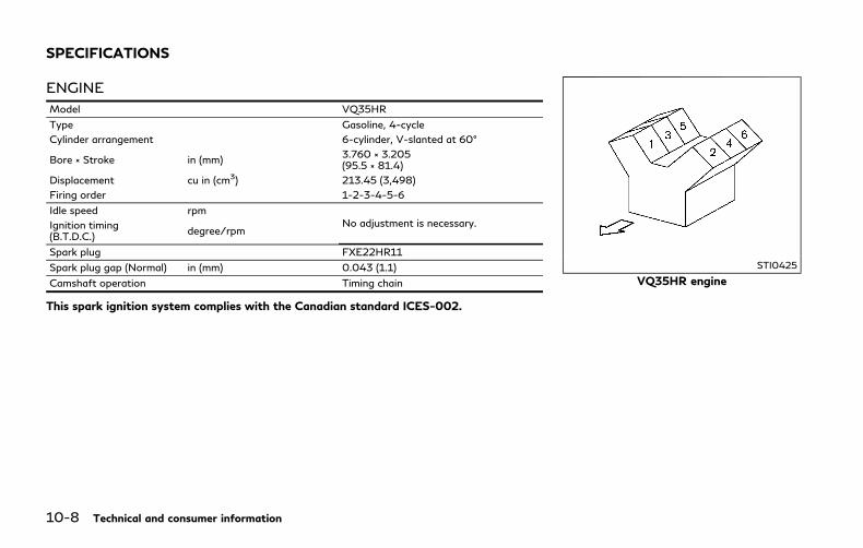
10-8 Technical and consumer information
ENGINE
Model VQ35HR
Type Gasoline, 4-cycle
Cylinder arrangement 6-cylinder, V-slanted at 60°
Bore × Stroke in (mm)3.760 × 3.205(95.5 × 81.4)
Displacement cu in (cm3) 213.45 (3,498)
Firing order 1-2-3-4-5-6
Idle speed rpmNo adjustment is necessary.Ignition timing
(B.T.D.C.)degree/rpm
Spark plug FXE22HR11
Spark plug gap (Normal) in (mm) 0.043 (1.1)
Camshaft operation Timing chain
This spark ignition system complies with the Canadian standard ICES-002.
STI0425
VQ35HR engine
SPECIFICATIONS
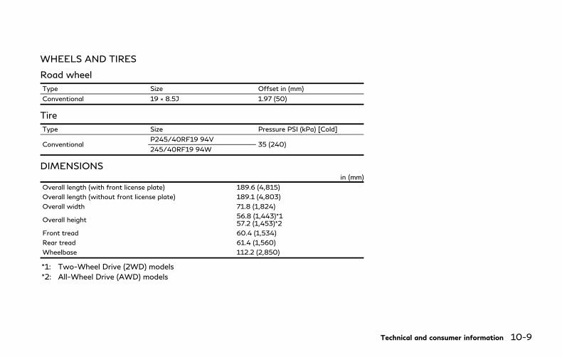
WHEELS AND TIRES
Road wheel
Type Size Offset in (mm)
Conventional 19 × 8.5J 1.97 (50)
Tire
Type Size Pressure PSI (kPa) [Cold]
ConventionalP245/40RF19 94V
35 (240)245/40RF19 94W
DIMENSIONSin (mm)
Overall length (with front license plate) 189.6 (4,815)
Overall length (without front license plate) 189.1 (4,803)
Overall width 71.8 (1,824)
Overall height56.8 (1,443)*157.2 (1,453)*2
Front tread 60.4 (1,534)
Rear tread 61.4 (1,560)
Wheelbase 112.2 (2,850)
*1: Two-Wheel Drive (2WD) models
*2: All-Wheel Drive (AWD) models
Technical and consumer information 10-9

10-10 Technical and consumer information
If you plan to travel in another country, youshould first find out if the fuel available issuitable for your vehicle’s engine.
Using fuel with too low an octane ratingmaycause engine damage. All gasoline vehiclesmust be operated with unleaded gasoline.Therefore, avoid taking your vehicle to areaswhere appropriate fuel is not available.
When transferring the registration of yourvehicle to another country, state, provinceor district, it may be necessary to modify thevehicle to meet local laws and regulations.
The laws and regulations for motor vehicleemission control and safety standards varyaccording to the country, state, province ordistrict; therefore, vehicle specifications maydiffer.
When any vehicle is to be taken intoanother country, state, province or districtand registered, its modifications, transpor-tation, and registration are the responsi-bility of the user. INFINITI is not responsiblefor any inconvenience that may result.
STI0716
VEHICLE IDENTIFICATION NUM-BER (VIN) PLATEThe vehicle identification number plate isattached as shown. This number is theidentification for your vehicle and is used inthe vehicle registration.
STI0717
VEHICLE IDENTIFICATION NUM-BER (chassis number)The number is stamped as shown in theengine compartment.
WHENTRAVELINGORREGISTERINGIN ANOTHER COUNTRY VEHICLE IDENTIFICATION
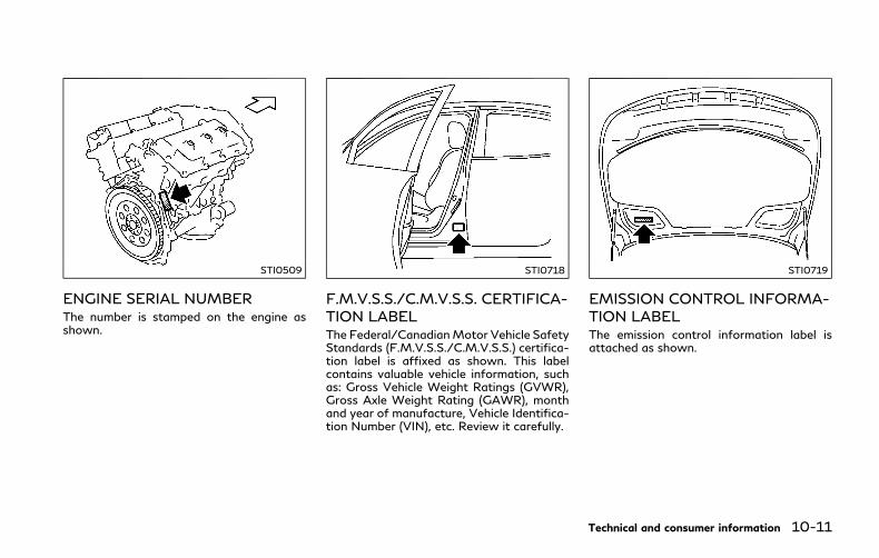
STI0509
ENGINE SERIAL NUMBERThe number is stamped on the engine asshown.
STI0718
F.M.V.S.S./C.M.V.S.S. CERTIFICA-TION LABELThe Federal/CanadianMotor Vehicle SafetyStandards (F.M.V.S.S./C.M.V.S.S.) certifica-tion label is affixed as shown. This labelcontains valuable vehicle information, suchas: Gross Vehicle Weight Ratings (GVWR),Gross Axle Weight Rating (GAWR), monthand year of manufacture, Vehicle Identifica-tion Number (VIN), etc. Review it carefully.
STI0719
EMISSION CONTROL INFORMA-TION LABELThe emission control information label isattached as shown.
Technical and consumer information 10-11

10-12 Technical and consumer information
JVT0220X
TIRE AND LOADING INFORMA-TION LABELThe cold tire pressure is shown on the Tireand Loading Information label affixed to thepillar as illustrated.
STI0721
AIR CONDITIONER SPECIFICA-TION LABELThe air conditioner specification label isattached as shown.

JVT0530X
Use the following steps to mount the licenseplate:
Before mounting the license plate, confirmthat the following parts are enclosed in theplastic bag.
Only use the recommended mounting posi-tion, otherwise the radar sensor (IntelligentCruise Control (ICC) system) (if so equipped)obstruction may result.
. License plate bracket
. J-nut × 2
. Screw × 2
. Screw grommet × 2
1. Park the vehicle on flat, level ground.
2. Locate the center position as illu-strated. Position the license plate brack-et at a distance of approximately 0.91 in(23 mm) from the bottom of thebumper. Hold the license plate bracketin place.
3. Mark the center of the hole with a felt-tip pen.
4. Carefully drill two pilot holes using a0.35 in (9 mm) drill bit at the markedlocations. (Be sure that the drill onlygoes through the bumper fascia.)
5. Insert grommets into the hole on thefascia.
6. Insert a flat-blade screwdriver into the
Technical and consumer information 10-13
INSTALLING FRONT LICENSE PLATE

10-14 Technical and consumer information
grommet hole to add 90° turn onto thepart .
7. Install the license plate bracket withscrews.
STI0623
Left sideThis vehicle is equipped with air deflectors infront of the front wheels. The deflectors willchange the air flow to help improve aero-dynamic performance.
When transporting your vehicle on a trailer,the air deflectors may interfere with a steepslope to a trailer bed. In this case, remove thedeflectors from the undercover of the ve-hicle.
1. Loosen three screws as shown andremove the left-side air deflector .
2. Tighten the removed screw in itsoriginal position.
3. Perform the same procedure to removethe right-side air deflector.
4. Store the two air deflectors and fourscrews to reinstall in the reverse order.
5. When reinstalling, make sure all sixscrews are firmly tightened on both airdeflectors.
REMOVING AIR DEFLECTORS

WARNING
. It is extremely dangerous toride in a cargo area inside thevehicle. In a collision, peopleriding in these areas are morelikely to be seriously injured orkilled.
. Do not allow people to ride inany area of vehicle that is notequipped with seats and seatbelts.
. Be sure everyone in your vehicleis in a seat and using a seat beltproperly.
TERMS
It is important to familiarize yourselfwith the following terms before load-ing your vehicle:. Curb Weight (actual weight of
your vehicle) - vehicle weight in-cluding: standard and optionalequipment, fluids, emergencytools, and spare tire assembly. Thisweight does not include passen-
gers and cargo.. GVW (Gross Vehicle Weight) -
curb weight plus the combinedweight of passengers and cargo.
. GVWR (Gross Vehicle Weight Rat-ing) - maximum total combinedweight of the unloaded vehicle,passengers, luggage, hitch, trailertongue load and any other op-tional equipment. This informationis located on the F.M.V.S.S./C.M.V.S.S. label.
. GAWR (Gross Axle Weight Rating)- maximum weight (load) limitspecified for the front or rear axle.This information is located on theF.M.V.S.S./C.M.V.S.S. label.
. GCWR (Gross Combined WeightRating) - The maximum totalweight rating of the vehicle, pas-sengers, cargo, and trailer.
. Vehicle Capacity Weight, Loadlimit, Total load capacity - max-imum total weight limit specifiedof the load (passengers and cargo)for the vehicle. This is the max-imum combined weight of occu-
pants and cargo that can beloaded into the vehicle. If thevehicle is used to tow a trailer,the trailer tongue weight must beincluded as part of the cargo load.This information is located on theTire and Loading Information la-bel.
. Cargo capacity - permissibleweight of cargo, the weight oftotal occupants weight subtractedfrom the load limit.
Technical and consumer information 10-15
VEHICLE LOADING INFORMATION
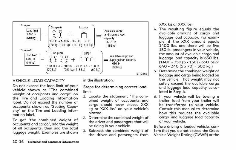
10-16 Technical and consumer information
STI0365
VEHICLE LOAD CAPACITY
Do not exceed the load limit of yourvehicle shown as “The combinedweight of occupants and cargo” onthe Tire and Loading Informationlabel. Do not exceed the number ofoccupants shown as “Seating Capa-city” on the Tire and Loading Infor-mation label.
To get “the combined weight ofoccupants and cargo”, add the weightof all occupants, then add the totalluggage weight. Examples are shown
in the illustration.
Steps for determining correct loadlimit1. Locate the statement “The com-
bined weight of occupants andcargo should never exceed XXXkg or XXX lbs” on your vehicle’splacard.
2. Determine the combined weight ofthe driver and passengers that willbe riding in your vehicle.
3. Subtract the combined weight ofthe driver and passengers from
XXX kg or XXX lbs.
4. The resulting figure equals theavailable amount of cargo andluggage load capacity. For exam-ple, if the XXX amount equals1400 lbs. and there will be five150 lb. passengers in your vehicle,the amount of available cargo andluggage load capacity is 650 lbs.(1400 − 750 (5 x 150) = 650 lbs or640 − 340 (5 x 70) = 300 kg.)
5. Determine the combined weight ofluggage and cargo being loaded onthe vehicle. That weight may notsafely exceed the available cargoand luggage load capacity calcu-lated in Step 4.
6. If your vehicle will be towing atrailer, load from your trailer willbe transferred to your vehicle.Consult this manual to determinehow this reduces the availablecargo and luggage load capacityof your vehicle.
Before driving a loaded vehicle, con-firm that you do not exceed the GrossVehicle Weight Rating (GVWR) or the

Gross Axle Weight Rating (GAWR)for your vehicle. (See “Measurementof weights” (P.10-17).)
Also check tires for proper inflationpressures. See the Tire and LoadingInformation label.
LOADING TIPS. The GVW must not exceed GVWR
or GAWR as specified on the F.M.V.S.S./C.M.V.S.S. certification la-bel.
. Do not load the front and rear axleto the GAWR. Doing so will exceedthe GVWR.
WARNING
. Properly secure all cargo to helpprevent it from sliding or shift-ing. Do not place cargo higherthan the seatbacks. In a suddenstop or collision, unsecured car-go could cause personal injury.
. Do not load your vehicle anyheavier than the GVWR or themaximum front and rear
GAWRs. If you do, parts ofyour vehicle can break, tiredamage could occur, or it canchange the way your vehiclehandles. This could result in lossof control and cause personalinjury.
. Overloading could not onlyshorten the life of your vehicleand the tires, but also couldlead to hazardous vehicle hand-ling and long braking distance.This may cause a premature tiremalfunction, which could resultin a serious accident and perso-nal injury. Failures caused byoverloading are not covered bythe vehicle’s warranty.
MEASUREMENT OF WEIGHTS
Secure loose items to prevent weightshifts that could affect the balance ofyour vehicle. When the vehicle isloaded, drive to a scale and weighthe front and the rear wheels sepa-rately to determine axle loads. Indivi-dual axle loads should not exceed
either of the gross axle weight ratings(GAWR). The total of the axle loadsshould not exceed the gross vehicleweight rating (GVWR). These ratingsare given on the vehicle certificationlabel. If weight ratings are exceeded,move or remove items to bring allweights below the ratings.
Technical and consumer information 10-17

10-18 Technical and consumer information
Do not tow a trailer with yourvehicle.
FLAT TOWINGTowing your vehicle with all four wheels onthe ground is sometimes called flat towing.This method is sometimes usedwhen towinga vehicle behind a recreational vehicle, suchas a motor home.
CAUTION
. Failure to follow these guidelines canresult in severe transmission damage.
. Whenever flat towing your vehicle,always tow forward, never back-ward.
. DO NOT tow any Automatic Trans-mission (AT) vehicle with all fourwheels on the ground (flat towing).Doing so WILL DAMAGE internaltransmission parts due to lack oftransmission lubrication.
. DO NOT tow any All-Wheel Drive(AWD) vehicle with any of the wheelson the ground. Doing so may causeserious and expensive damage to thepowertrain.
. For emergency towing proceduresrefer to “Towing recommended by
INFINITI” (P.6-10).
Automatic Transmission (AT)
All-Wheel Drive (AWD) models:
Do not tow an AWD vehicle with any of thewheels on the ground.
Two-Wheel Drive (2WD) models:
To tow a vehicle equippedwith an automatictransmission, an appropriate vehicle dollyMUST be placed under the towed vehicle’sdrive wheels. Always follow the dolly man-ufacturer’s recommendations when usingtheir product.
DOT (Department Of Transportation) Qual-ity Grades: All passenger car tires mustconform to federal safety requirements inaddition to these grades.
Quality grades can be found where applic-able on the tire sidewall between treadshoulder and maximum section width. Forexample:
Treadwear 200 Traction AA Temperature A
TREADWEARThe treadwear grade is a comparative ratingbased on the wear rate of the tire whentested under controlled conditions on aspecified government test course. For ex-ample, a tire graded 150 would wear oneand one-half (1 1/2) times as well on thegovernment course as a tire graded 100.The relative performance of tires dependsupon actual conditions of their use, however,and may depart significantly from the normdue to variations in driving habits, servicepractices and differences in road character-istics and climate.
TOWING A TRAILER UNIFORMTIREQUALITY GRADING
TRACTION AA, A, B AND CThe traction grades, from highest to lowest,are AA, A, B and C. Those grades representthe tire’s ability to stop on wet pavement asmeasured under controlled conditions onspecified government test surfaces of as-phalt and concrete. A tire marked C mayhave poor traction performance.
WARNING
The traction grade assigned to this tire isbased on straight-ahead braking trac-tion tests, and does not include accel-eration, cornering, hydroplaning, or peaktraction characteristics.
TEMPERATURE A, B AND CThe temperature grades A (the highest), B,and C, representing the tire’s resistance tothe generation of heat and its ability todissipate heat when tested under controlledconditions on a specified indoor laboratorytest wheel. Sustained high temperature cancause the material of the tire to degenerateand reduce tire life, and excessive tempera-ture can lead to sudden tire failure. Thegrade C corresponds to a level of perfor-mance which all passenger car tires mustmeet under the Federal Motor Vehicle
Safety Standard No. 109. Grades B and Arepresent higher levels of performance onthe laboratory test wheel than the minimumrequired by law.
WARNING
The temperature grade for this tire isestablished for a tire that is properlyinflated and not overloaded. Excessivespeed, under-inflation, or excessiveloading, either separately or in combina-tion, can cause heat build-up and possi-ble tire failure.
Your INFINITI is covered by the followingemission warranties.
For USA:
. Emission Defects Warranty
. Emissions Performance Warranty
Details of these warranties may be foundwith other vehicle warranties in your War-ranty Information Booklet that comes withyour INFINITI. If you did not receive aWarranty Information Booklet, or it hasbecome lost, you may obtain a replacementby writing to:
. INFINITI Division
Nissan North America, Inc.
Consumer Affairs Department
P.O. Box 685003
Franklin, TN 37068-5003
For Canada:
Emission Control System Warranty
Details of these warranties may be foundwith other vehicle warranties in your War-ranty and Roadside Assistance Informationthat comes with your INFINITI. If you did notreceive aWarranty and Roadside AssistanceInformation, or it has become lost, you mayobtain a replacement by writing to:
. Nissan Canada Inc.
5290 Orbitor Drive
Mississauga, Ontario,
L4W 4Z5
Technical and consumer information 10-19
EMISSION CONTROL SYSTEMWARRANTY
10-20 Technical and consumer information
For USA
If you believe that your vehicle has adefect which could cause a crash orcould cause injury or death, youshould immediately inform the Na-tional Highway Traffic Safety Admin-istration (NHTSA) in addition tonotifying INFINITI.
If NHTSA receives similar complaints,it may open an investigation, and if itfinds that a safety defect exists in agroup of vehicles, it may order a recalland remedy campaign. However,NHTSA cannot become involved inindividual problems between you,your retailer, or INFINITI.
To contact NHTSA, you may call theVehicle Safety Hotline toll-free at 1-888-327-4236 (TTY: 1-800-424-9153); go to http://www.safercar.gov; or write to: Administrator,NHTSA, 400 Seventh Street, SW.,Washington DC 20590. You can alsoobtain other information about motorvehicle safety from http://www.safercar. gov.
You may notify INFINITI by contact-
ing our Consumer Affairs Depart-ment, toll-free, at 1-800-662-6200.
For Canada
If you believe that your vehicle has adefect which could cause a crash orcould cause injury or death, youshould immediately inform TransportCanada in addition to notifyingINFINITI.
If Transport Canada receives com-plaints, it may open an investigation,and if it finds that a safety defectexists in a group of vehicles, it mayrequest that INFINITI conduct a recallcampaign. However, Transport Cana-da cannot become involved in indivi-dual problems between you, yourretailer, or INFINITI.
You may contact Transport Canada’sDefect Investigations and Recalls Di-vision toll free at 1-800-333-0510.You may also report safety defectsonline at:
https://wwwapps.tc.gc.ca/Saf-Sec-Sur/7/PCDB-BDPP/fc-cp.aspx?lan-g=eng (English speakers) or https://
wwwapps.tc.gc.ca/Saf-Sec-Sur/7/PCDB-BDPP/fc-cp.aspx?lang=fra(French speakers).
Additional information concerningmotor vehicle safety may be obtainedfrom Transport Canada’s RoadSafety Information Centre at 1-800-333-0371 or online at www.tc.gc.ca/ roadsafety (English speakers)or www.tc.gc.ca/securiteroutiere(French speakers).
To notify INFINITI of any safetyconcerns please contact our Consu-mer Information Centre toll free at 1-800- 361-4792.
REPORTING SAFETY DEFECTS
WARNING
A vehicle equipped with Intelligent All-Wheel Drive (AWD) should never betested using a two wheel dynamometer(such as the dynamometers used bysome states for emissions testing), orsimilar equipment. Make sure you informtest facility personnel that your vehicleis equipped with AWD before it is placedon a dynamometer. Using the wrong testequipment may result in transmissiondamage or unexpected vehicle move-mentwhich could result in serious vehicledamage or personal injury.
Due to legal requirements in some states/areas, your vehicle may be required to be inwhat is called the “ready condition” for anInspection/Maintenance (I/M) test of theemission control system.
The vehicle is set to the “ready condition”when it is driven through certain drivingpatterns. Usually, the “ready condition” canbe obtained by ordinary usage of the vehicle.
If a powertrain system component is re-paired or the 12-volt battery is discon-nected, the vehicle may be reset to a “notready condition”. Before taking the I/M test,check the vehicle’s inspection/maintenance
test readiness condition. Place the ignitionswitch in the ON position without startingthe engine. If the Malfunction IndicatorLight (MIL) comes on steady for 20 secondsand then blinks for 10 seconds, the I/M testcondition is “not ready”. If the MIL does notblink after 20 seconds, the I/M test condi-tion is “ready”.
It is recommended you visit an INFINITIretailer to set the “ready condition” or toprepare the vehicle for testing.
This vehicle is equipped with an Event DataRecorder (EDR). The main purpose of anEDR is to record, in certain crash or nearcrash-like situations, such as an air bagdeployment or hitting a road obstacle, datathat will assist in understanding how avehicle’s systems performed. The EDR isdesigned to record data related to vehicledynamics and safety systems for a shortperiod of time, typically 30 seconds or less.The EDR in this vehicle is designed to recordsuch data as:
. How various systems in your vehicle wereoperating;
. Whether or not the driver and passengersafety belts were buckled/fastened;
. How far (if at all) the driver was depres-sing the accelerator and/or brake pedal;and,
. How fast the vehicle was traveling.
. Sounds are not recorded.
These data can help provide a better under-standing of the circumstances in whichcrashes and injuries occur.
NOTE: EDR data are recorded by yourvehicle only if a nontrivial crash situationoccurs; no data are recorded by the EDRunder normal driving conditions and nopersonal data (e.g. name, gender, age andcrash location) are recorded. However, otherparties, such as law enforcement, couldcombine the EDR data with the type of
Technical and consumer information 10-21
READINESS FOR INSPECTION/MAINTENANCE (I/M) TEST (US only) EVENT DATA RECORDERS (EDR)

10-22 Technical and consumer information
personally identifying data routinely ac-quired during a crash investigation.
To read data recorded by an EDR, specialequipment is required and access to thevehicle or the EDR is needed. In addition tothe vehicle manufacturer and INFINITI re-tailer, other parties, such as law enforce-ment, that have the special equipment, canread the information if they have access tothe vehicle or the EDR. EDR data will only beaccessed with the consent of the vehicleowner or lessee or as otherwise required orpermitted by law.
Genuine INFINITI Service Manual for thismodel year and prior can be purchased. Agenuine INFINITI Service Manual is the bestsource of service and repair information foryour vehicle. This manual is the same oneused by the factory-trained techniciansworking at INFINITI retailers. GenuineINFINITI Owner’s Manuals can also bepurchased.
For USA:
For current pricing and availability of genu-ine INFINITI Service Manuals, contact:
1-800-450-9491www.infiniti-techinfo.com
For current pricing and availability of genu-ine INFINITI Owner’s Manuals, contact:
1-800-247-5321
For Canada:
To purchase a copy of a genuine INFINITIService Manual or Owner’s Manual for thismodel year and prior, contact an INFINITIretailer. For the phone number and locationof an INFINITI retailer in your area call theINFINITI Satisfaction Center at 1-800-361-4792 and a bilingual INFINITI representativewill assist you.
OWNER’S MANUAL/SERVICEMANUAL ORDER INFORMATION
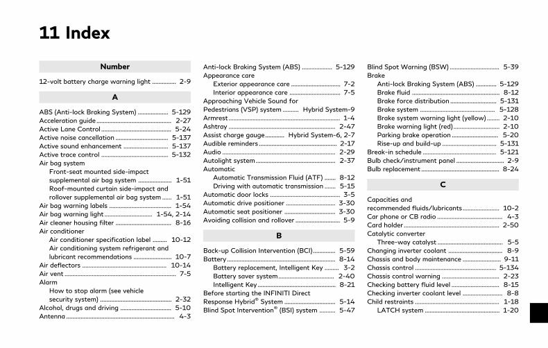
11 Index
Number
12-volt battery charge warning light ............... 2-9
A
ABS (Anti-lock Braking System) ................... 5-129
Acceleration guide ............................................... 2-27
Active Lane Control ............................................ 5-24
Active noise cancellation ................................. 5-137
Active sound enhancement ............................ 5-137
Active trace control .......................................... 5-132
Air bag system
Front-seat mounted side-impact
supplemental air bag system ..................... 1-51
Roof-mounted curtain side-impact and
rollover supplemental air bag system ...... 1-51
Air bag warning labels ....................................... 1-54
Air bag warning light .............................. 1-54, 2-14
Air cleaner housing filter ................................... 8-16
Air conditioner
Air conditioner specification label ......... 10-12
Air conditioning system refrigerant and
lubricant recommendations ........................ 10-7
Air deflectors ..................................................... 10-14
Air vent ...................................................................... 7-5
Alarm
How to stop alarm (see vehicle
security system) ............................................. 2-32
Alcohol, drugs and driving ................................ 5-10
Antenna .................................................................... 4-3
Anti-lock Braking System (ABS) ................... 5-129
Appearance care
Exterior appearance care ............................... 7-2
Interior appearance care ................................ 7-5
Approaching Vehicle Sound for
Pedestrians (VSP) system .......... Hybrid System-9
Armrest ...................................................................... 1-4
Ashtray ................................................................... 2-47
Assist charge gauge............ Hybrid System-6, 2-7
Audible reminders ................................................. 2-17
Audio ....................................................................... 2-29
Autolight system.................................................. 2-37
Automatic
Automatic Transmission Fluid (ATF) ....... 8-12
Driving with automatic transmission ....... 5-15
Automatic door locks ............................................ 3-5
Automatic drive positioner ............................... 3-30
Automatic seat positioner ................................ 3-30
Avoiding collision and rollover ............................ 5-9
B
Back-up Collision Intervention (BCI).............. 5-59
Battery .................................................................... 8-14
Battery replacement, Intelligent Key ......... 3-2
Battery saver system................................... 2-40
Intelligent Key ................................................. 8-21
Before starting the INFINITI Direct
Response Hybrid® System ................................ 5-14
Blind Spot Intervention® (BSI) system .......... 5-47
Blind Spot Warning (BSW) ............................... 5-39
Brake
Anti-lock Braking System (ABS) ............. 5-129
Brake fluid ....................................................... 8-12
Brake force distribution ............................. 5-131
Brake system ............................................... 5-128
Brake system warning light (yellow) ........ 2-10
Brake warning light (red) ............................. 2-10
Parking brake operation ............................. 5-20
Rise-up and build-up .................................. 5-131
Break-in schedule .............................................. 5-121
Bulb check/instrument panel .............................. 2-9
Bulb replacement ................................................. 8-24
C
Capacities and
recommended fluids/lubricants ....................... 10-2
Car phone or CB radio ......................................... 4-3
Card holder ............................................................ 2-50
Catalytic converter
Three-way catalyst ......................................... 5-5
Changing inverter coolant .................................. 8-9
Chassis and body maintenance ........................ 9-11
Chassis control ................................................... 5-134
Chassis control warning .................................... 2-23
Checking battery fluid level .............................. 8-15
Checking inverter coolant level ......................... 8-8
Child restraints ..................................................... 1-18
LATCH system ............................................... 1-20

11-2
Precautions on child restraints .................. 1-18
Child safety ............................................................ 1-16
Child safety rear door lock .................................. 3-6
Chimes
Audible reminders .......................................... 2-17
Seat belt warning light and chime ............ 2-14
Circuit breaker
Fusible link ...................................................... 8-20
Cleaning exterior and interior .................... 7-2, 7-5
Clock........................................................................ 2-30
Coat hooks ............................................................ 2-51
Cockpit ...................................................................... 2-3
Cold weather driving ........................................ 5-135
Console box........................................................... 2-50
Coolant
Capacities and
recommended fluids/lubricants ................. 10-2
Changing engine coolant ............................... 8-7
Checking engine coolant level ...................... 8-6
Corrosion protection ............................................. 7-8
Courtesy light ....................................................... 2-59
Cruise control ....................................................... 5-70
Fixed speed cruise control (on
ICC system) ..................................................... 5-89
Intelligent Cruise Control (ICC) ................. 5-72
Cruise indicator .................................................... 2-23
Cup holders ........................................................... 2-47
Current fuel consumption ................................. 2-28
D
Daytime running light system .......................... 2-40
Defroster switch
Rear window and outside mirror
defroster switch ............................................. 2-36
Dimensions ............................................................ 10-9
Direct Adaptive Steering ................................. 5-126
Direct Response Hybrid® System warning
light (hybrid system warning light) .................. 2-11
Distance Control Assist (DCA) ........................ 5-93
Distance to empty ............................................... 2-29
Drive positioner .................................................... 3-30
Driver assist system indicator .......................... 2-24
Driving
Cold weather driving .................................. 5-135
Driving with automatic transmission ....... 5-15
Precautions when starting and driving ..... 5-4
Driving aids ............................................................ 2-29
E
ECO drive indicator light ................................... 2-15
ECO mode ............................................................. 5-21
ECO pedal system ............................................... 5-22
Economy
Fuel .................................................................. 5-122
Efficient use of your vehicle ...... Hybrid System-8
Elapsed time ......................................................... 2-29
Elapsed time and trip odometer ..................... 2-29
Emergency shut-off system ...... Hybrid System-4
Emission control information label ............... 10-11
Emission control system maintenance ............ 9-8
Emission control system warranty ............... 10-19
Energy flow .................................... Hybrid System-6
Energy monitor .................................................... 2-27
Energy monitors ........................... Hybrid System-5
engine
Break-in schedule ........................................ 5-121
Capacities and
recommended fluids/lubricants ................. 10-2
Changing engine coolant ............................... 8-7
Changing engine oil and oil filter ............. 8-10
Checking engine coolant level ...................... 8-6
Checking engine oil level ............................... 8-9
Emergency hybrid system shut off .......... 5-13
Engine block heater ................................... 5-136
Engine compartment check locations ........ 8-3
Engine cooling system ................................... 8-5
Engine oil ........................................................... 8-9
Engine oil and filter
replacement indicator ................................... 2-25
Engine oil and oil
filter recommendation .................................. 10-6
Engine oil viscosity ........................................ 10-7
Engine serial number .................................. 10-11
Engine specifications ................................... 10-8
If your vehicle overheats ............................... 6-8
Remote engine start indicator ................... 2-21
Engine coolant temperature gauge................ 2-29
Entry/exit function
Automatic drive positioner ........................ 3-30
EV mode odometer and twin
trip odometer ........................................................ 2-27
Event Data Recorders (EDR) ......................... 10-21
Exhaust gas (carbon monoxide) ........................ 5-4
Explanation of scheduled
maintenance items ................................................. 9-5
F
F.M.V.S.S./C.M.V.S.S. certification label .... 10-11
Filter
Air cleaner housing filter ............................. 8-16
Changing engine oil and oil filter ............. 8-10
Flashers (See hazard warning
flasher switch) ......................................................... 6-2
Flat tire ...................................................................... 6-3
Flat Tire - Visit dealer warning ....................... 2-22
Flat towing ......................................................... 10-18
Floor mat cleaning ................................................. 7-6
Floor mat installation ............................................ 7-7
Fluid
Automatic Transmission Fluid (ATF) ....... 8-12
Brake fluid ....................................................... 8-12
Capacities and
recommended fluids/lubricants ................. 10-2
Engine coolant.................................................. 8-5
Engine oil ........................................................... 8-9
Window washer fluid ................................... 8-13
Fog light switch ................................................... 2-43
Forward Emergency Braking (FEB) ............ 5-104
Forward Emergency Braking (FEB) system
warning light .......................................................... 2-11
Front passenger air bag and status light ..... 1-45
Front power seat adjustment ............................. 1-3
Front seat
Front seat adjustment .................................... 1-3
Fuel
Capacities and
recommended fluids/lubricants ................. 10-2
Fuel economy ............................................... 5-122
Fuel octane rating ........................................ 10-4
Fuel recommendation.................................. 10-4
Fuel-filler cap .................................................. 3-24
Fuel-filler door ............................................... 3-24
Gauge................................................................... 2-7
Fuel economy history .................. Hybrid System-7
Fuel Efficient Driving Tips .............................. 5-121
Fuses ....................................................................... 8-19
Fusible links ........................................................... 8-20
G
Garage door opener
HomeLink® Universal Transceiver ............ 2-59
Gas cap ................................................................... 3-24
Gauge......................................................................... 2-5
Engine coolant temperature gauge.......... 2-29
Fuel gauge .......................................................... 2-7
Odometer ........................................................... 2-6
Speedometer ..................................................... 2-6
Tachometer ........................................................ 2-7
Trip computer ................................................. 2-27
General maintenance ............................................. 9-2
Glove box ............................................................... 2-49
H
Hazard warning flasher switch........................... 6-2
Head restraints/headrests .................................. 1-5
Headlights
Aiming control (See Adaptive Front
lighting System (AFS)) ................................. 2-41
Headlight switch ............................................ 2-36
Heated seats ......................................................... 2-44
Heated steering wheel ....................................... 2-45
Heater
Engine block heater ................................... 5-136
High beam assist ................................................. 2-38
High temperature warning ............................... 2-22
High voltage cautions ................. Hybrid System-2
High voltage components ....... Hybrid System-10
Hill start assist system ..................................... 5-134
HomeLink® Universal Transceiver .................. 2-59
Hood release ......................................................... 3-21
Hook
Coat hooks ...................................................... 2-51
Trunk hooks .................................................... 2-51
Horn......................................................................... 2-43
Hybrid system over heat warning .................. 2-22
Hybrid system start operation indicator....... 2-20
Hybrid
vehicle characteristics ............... Hybrid System-11
Hybrid vehicle precautions...... Hybrid System-10
11-3

11-4
I
If the vehicle does not start ................................ 6-5
Ignition switch
(Push-button) ................................................. 5-11
Automatic transmission models ................ 5-15
Immobilizer system.............................................. 2-32
Indicator
Vehicle information display ........................ 2-18
Indicator lights ...................................................... 2-15
INFINITI Direct Response
Hybrid® System............................. Hybrid System-2
Before starting the INFINITI Direct
Response Hybrid® System .......................... 5-14
Starting the INFINITI Direct Response
Hybrid® System.............................................. 5-14
INFINITI Drive Mode Selector ......................... 5-21
Infiniti InTouch Owner’s Manual ...................... 4-2
INFINITI Vehicle Immobilizer System ............ 2-32
Engine start ..................................................... 2-32
Inside mirror .......................................................... 3-28
Inspection/maintenance (I/M) test .............. 10-21
Instrument brightness control ......................... 2-42
Instrument panel .................................................... 2-4
Intelligent All-Wheel Drive (AWD) ............... 5-123
Intelligent Cruise Control (ICC) ....................... 5-72
Intelligent Cruise Control (ICC) system
ON indicator ......................................................... 2-24
Intelligent Key .......................................................... 3-2
Intelligent Key system ........................................... 3-6
Battery replacement ..................................... 8-21
Key operating range ....................................... 3-8
Key operation ................................................... 3-9
Warning signals.............................................. 3-13
Interior light control switch .............................. 2-57
Interior light replacement .................................. 8-25
Interior lights ......................................................... 2-56
Interior trunk lid release .................................... 3-24
Inverter cooling system......................................... 8-7
ISOFIX child restraint ......................................... 1-20
J
Jump starting........................................................... 6-5
K
Keyless entry (See remote keyless
entry system) ........................................................ 3-15
Keys ............................................................................ 3-2
For Intelligent Key system ............................ 3-6
L
Labels
Air bag warning labels ................................. 1-54
Air conditioner specification label ......... 10-12
Emission control information label ......... 10-11
Engine serial number .................................. 10-11
F.M.V.S.S./C.M.V.S.S.
certification label ......................................... 10-11
Tire and Loading
information label ............................. 8-30, 10-12
Vehicle identification number (VIN) ...... 10-10
Lane Departure Warning (LDW)/Lane
Departure Prevention (LDP) ............................ 5-32
LATCH system ..................................................... 1-20
License plate
Installing front license plate .................... 10-13
Light
Air bag warning light .................................... 1-54
Bulb replacement .......................................... 8-24
Fog light switch ............................................. 2-43
Headlight switch ............................................ 2-36
Indicator lights ................................................ 2-15
Interior light control switch ........................ 2-57
Interior lights ................................................... 2-56
Map lights ........................................................ 2-56
Personal lights ................................................ 2-57
Replacement .................................................. 8-24
Trunk light ....................................................... 2-58
Vanity mirror lights ....................................... 2-58
Warning/indicator lights and
audible reminders ............................................ 2-9
Lights
Exterior and interior light replacement .... 8-25
Lithium-ion (Li-ion) battery ....... Hybrid System-2
Loading information (See vehicle
loading information) ......................................... 10-15
Lock
Automatic door locks ..................................... 3-5
Door locks .......................................................... 3-4
Power door lock............................................... 3-4
Trunk lid ........................................................... 3-22

Locking with mechanical key ............................. 3-4
Log-in function .................................................... 3-15
Loose Fuel Cap warning ....................... 2-21, 3-26
Low fuel warning light ....................................... 2-12
Low outside temperature warning................. 2-23
Low tire pressure warning light ...................... 2-12
Low tire pressure warning system (See Tire
Pressure Monitoring
System (TPMS)) ................................ 5-5, 6-3, 8-28
M
Maintenance
Battery .............................................................. 8-14
General maintenance ...................................... 9-2
HEV Li-ion battery
replacement record ....................................... 9-14
Indicators for maintenance (vehicle
information display) ...................................... 2-25
Inside the vehicle ............................................. 9-3
Maintenance log ............................................ 9-16
Maintenance precautions .............................. 8-2
Maintenance requirements ........................... 9-2
Maintenance schedules ................................. 9-6
Maintenance under severe
driving conditions .......................................... 9-13
Outside the vehicle ......................................... 9-2
Seat belt maintenance ................................. 1-15
Standard maintenance .................................... 9-7
Under the hood and vehicle ......................... 9-4
Maintenance schedules ........................................ 9-6
Malfunction Indicator Light (MIL) .................. 2-16
Map lights .............................................................. 2-56
Master warning light .......................................... 2-13
Mechanical key (Intelligent Key system) .......... 3-3
Memory storage
Automatic drive positioner ......................... 3-31
Meter
Trip computer ................................................. 2-27
Meters and gauges ................................................ 2-5
Instrument brightness control ................... 2-42
Mirror
Inside mirror .................................................... 3-28
Outside mirrors .............................................. 3-29
Vanity mirror .................................................. 3-30
Moonroof ............................................................... 2-54
N
NAVI Shift Control .............................................. 5-19
New vehicle break-in ........................................ 5-121
Noise and vibration .................... Hybrid System-12
O
Odometer .................................................................. 2-6
Off-road recovery .................................................. 5-9
Oil
Capacities and
recommended fluids/lubricants ................. 10-2
Changing engine oil and oil filter ............. 8-10
Checking engine oil level ............................... 8-9
Engine oil ........................................................... 8-9
Engine oil viscosity ........................................ 10-7
One touch unlock sensor (See Intelligent
Key system) .............................................................. 3-9
Operation
Indicators for operation............................... 2-20
Operation of the INFINITI Direct
Response Hybrid® System ......... Hybrid System-4
Outside mirrors .................................................... 3-29
Overheat, If your vehicle overheats ................. 6-8
Owner’s Manual/Service Manual
order information ............................................. 10-22
P
Panic alarm............................................................ 3-17
Parking
Parking brake operation ............................. 5-20
Parking on hills ............................................. 5-125
Parking brake break-in .................................... 5-129
Personal lights ...................................................... 2-57
PERSONAL mode ............................................... 5-23
Phone
Car phone or CB radio ................................... 4-3
Power
Power door lock............................................... 3-4
Power outlet ................................................... 2-46
Power steering system .............................. 5-126
Power windows ............................................. 2-52
Power moonroof ................................................. 2-54
Power steering warning light........................... 2-14
Precautions
Braking precautions ................................... 5-128
Child restraints ............................................... 1-18
11-5
11-6
Cruise control ................................................. 5-70
Maintenance ..................................................... 8-2
Seat belt usage ................................................. 1-9
Supplemental restraint system .................. 1-37
When starting and driving ............................ 5-4
Pre-crash seat belts with
comfort function ................................................... 1-11
Predictive Forward Collision
Warning (PFCW) ............................................... 5-112
Push starting............................................................ 6-7
Push-button ignition switch .................. 5-11, 5-12
R
Radio
Car phone or CB radio ................................... 4-3
Rain-sensing auto wiper system ..................... 2-35
Rapid air pressure loss .......................................... 5-9
Readiness for inspection/maintenance
(I/M) test (US only) ........................................... 10-21
Rear door lock
Child safety rear door lock ........................... 3-6
Rear window and outside mirror
defroster switch ................................................... 2-36
Recorders
Event data .................................................... 10-21
Regenerative brake ...................... Hybrid System-8
Registering in another country ..................... 10-10
Remote engine start ........................................... 3-19
Remote keyless entry system .......................... 3-15
Reporting safety defects ................................ 10-20
Request switch (See Intelligent
Key system) .............................................................. 3-9
Road accident cautions .............. Hybrid System-3
Roadside assistance program ............................. 6-2
Rollover ..................................................................... 5-9
Roof
Moonroof ......................................................... 2-55
Run-flat tires .......................................................... 6-4
S
Safety
Child seat belts ............................................... 1-16
Reporting safety defects .......................... 10-20
Seat adjustment
Front power seat adjustment ....................... 1-3
Front seats ......................................................... 1-3
Seat belt(s)
Child safety ..................................................... 1-16
Infants ............................................................... 1-16
Injured persons ................................................ 1-11
Larger children ............................................... 1-17
Precautions on seat belt usage .................... 1-9
Pre-crash seat belts with
comfort function ............................................. 1-11
Pregnant women ............................................ 1-11
Seat belt cleaning ............................................. 7-7
Seat belt extenders ....................................... 1-15
Seat belt maintenance ................................. 1-15
Seat belt warning light and chime ............ 2-14
Seat belts ............................................................ 1-9
Seat belts with pretensioners .................... 1-53
Shoulder belt height adjustment ............... 1-14
Small children.................................................. 1-17
Three-point type ............................................ 1-12
Seat(s)
Driver-side memory ..................................... 3-30
Heated seats .................................................. 2-44
Seats .................................................................... 1-2
Security system
Vehicle security system................................ 2-31
Security system (INFINITI Vehicle
Immobilizer System)
Engine start ..................................................... 2-32
Shift lever
Shift lock release ........................................... 5-18
Shift lock release, Transmission ...................... 5-18
SHIFT “P” warning .............................................. 2-20
Shifting
Automatic transmission ............................... 5-15
Shoulder belt height adjustment ..................... 1-14
SNOW mode......................................................... 5-21
Spark plugs ............................................................ 8-15
Speedometer ............................................................ 2-6
SPORT mode ........................................................ 5-21
Standard maintenance .......................................... 9-7
STANDARD mode ............................................... 5-21
Starting
Before starting the INFINITI Direct
Response Hybrid® System .......................... 5-14
Jump starting.................................................. 8-15
Precautions when starting and driving ..... 5-4
Push starting...................................................... 6-7
Starting the INFINITI Direct Response
Hybrid® System.............................................. 5-14
Status light, Front passenger air bag ............ 1-45
Steering
Direct Adaptive Steering ........................... 5-126
Heated steering wheel ................................. 2-45
Power steering system .............................. 5-126
Tilt/telescopic steering ................................ 3-27
Storage ................................................................... 2-47
Storage box ........................................................... 2-50
Sun visors ............................................................... 3-27
Sunglasses holder ................................................ 2-49
Supplemental air bag warning labels ............. 1-54
Supplemental air bag warning light ... 1-54, 2-14
Supplemental restraint system ........................ 1-37
Precautions on supplemental
restraint system ............................................. 1-37
Switch
Autolight switch............................................. 2-37
Fog light switch ............................................. 2-43
Hazard warning flasher switch.................... 6-2
Headlight switch ............................................ 2-36
Ignition switch ................................................ 5-15
Power door lock switch ................................. 3-5
Rear window and outside mirror
defroster switch ............................................. 2-36
Turn signal switch ......................................... 2-42
Vehicle Dynamic Control (VDC)
off switch ......................................................... 2-43
T
Tachometer .............................................................. 2-7
Temperature
Engine coolant temperature gauge.......... 2-29
Theft (INFINITI Vehicle Immobilizer System)
Engine start ..................................................... 2-32
Three-way catalyst ................................................ 5-5
Tilt/telescopic steering ...................................... 3-27
Tire
Flat Tire - Visit dealer warning ................. 2-22
Run-flat tires .................................................... 6-4
Tire replacement indicator .......................... 2-25
Tire rotation .................................................... 8-36
Tire pressure
Low tire pressure warning light ................ 2-12
Tire Pressure Low - Add Air warning ........... 2-21
Tires
Flat tire ............................................................... 6-3
Low tire pressure
warning system ........................... 5-5, 6-3, 8-28
Run-flat tires ................................................. 8-34
Tire and Loading
information label ............................. 8-30, 10-12
Tire chains........................................................ 8-35
Tire dressing ...................................................... 7-4
Tire pressure .................................................. 8-28
Tire Pressure Monitoring
System (TPMS) ........................... 5-5, 6-3, 8-28
Types of tires ................................................. 8-34
Uniform tire quality grading .................... 10-18
Wheel/tire size ............................................... 10-9
Wheels and tires ........................................... 8-28
Towing
Flat towing ................................................... 10-18
Tow truck towing ............................................ 6-9
Towing a trailer ........................................... 10-18
TPMS
Tire Pressure
Monitoring System .................... 5-5, 6-3, 8-28
TPMS with Tire Inflation Indicator ............ 5-8
Trailer towing .................................................... 10-18
Transceiver
HomeLink® Universal Transceiver ............ 2-59
Transmission
Automatic Transmission Fluid (ATF) ....... 8-12
Driving with automatic transmission ....... 5-15
Transmission shift lever lock release ....... 5-18
Transmitter (See remote keyless
entry system) ........................................................ 3-15
Traveling or registering in
another country ................................................ 10-10
Trip computer ....................................................... 2-27
Trip odometer ....................................................... 2-29
Trunk
Interior trunk lid release .............................. 3-24
Light .................................................................. 2-58
Trunk hooks .................................................... 2-51
Trunk lid ........................................................... 3-22
Trunk lid release switch ............................... 3-22
Trunk open request switch ......................... 3-22
Trunk release power cancel switch .......... 3-23
11-7
11-8
Turn signal switch ............................................... 2-42
U
Underbody cleaning ............................................... 7-3
Uniform tire quality grading .......................... 10-18
V
Vanity mirror ......................................................... 3-30
Vanity mirror lights ............................................. 2-58
Vehicle
Dimensions ...................................................... 10-9
Recovery (freeing a stuck vehicle) ............ 6-11
Vehicle Dynamic Control (VDC)
off switch ......................................................... 2-43
Vehicle Dynamic Control
(VDC) system ............................................... 5-130
Vehicle Dynamic Control (VDC)
warning light ................................................... 2-15
Vehicle identification number (VIN) ............ 10-10
Vehicle information display .............................. 2-18
Vehicle loading information............................ 10-15
Vehicle security system...................................... 2-31
Vehicle speedAverage speed............................ 2-28
Ventilators ............................................................... 4-2
W
Warning
Blind Spot Warning (BSW) system .......... 5-41
Flat Tire - Visit dealer warning ................. 2-22
Hazard warning flasher switch.................... 6-2
Predictive Forward Collision
Warning (PFCW) ......................................... 5-112
Tire Pressure Monitoring
System (TPMS) ........................... 5-5, 6-3, 8-28
Vehicle information display ........................ 2-18
Warning lights .................................................. 2-9
Warning lights, indicator lights and
audible reminders ............................................ 2-9
Warning labels
Air bag warning labels ................................. 1-54
Warning light ........................................................... 2-9
Air bag warning light ........................ 1-54, 2-14
Anti-lock Braking System (ABS)
warning light ................................................... 2-10
Brake system warning light (yellow) ........ 2-10
Brake warning light (red) ............................. 2-10
Direct Response Hybrid® System warning
light (hybrid system warning light) ........... 2-11
Forward Emergency Braking (FEB)
system warning light .................................... 2-11
Low fuel warning light ................................. 2-12
Low tire pressure warning light ................ 2-12
Power steering warning light..................... 2-14
Seat belt warning light and chime ............ 2-14
Warranty
Emission control system warranty ........ 10-19
Washer switch
Wiper and washer switch ........................... 2-34
Washing .................................................................... 7-2
Waxing....................................................................... 7-2
Welcome light and farewell light function .... 3-10
Wheel/tire size ..................................................... 10-9
Wheels and tires .................................................. 8-28
Care of wheels .................................................. 7-3
Cleaning aluminum alloy wheels .................. 7-3
Cleaning bright wheels .................................. 7-4
Window washer fluid ......................................... 8-13
Window(s)
Cleaning............................................................... 7-3
Power windows ............................................. 2-52
Wiper
Rain-sensing auto wiper system ............... 2-35
Wiper and washer switch ........................... 2-34
Wiper blades ................................................... 8-17
Wiper and washer switch ................................. 2-34

MEMO
11-9

FUEL INFORMATION:Use unleaded premium gasoline with anoctane rating of at least 91 AKI (Anti-KnockIndex) number (Research octane number 96).
If premium gasoline is not available, un-leaded regular gasoline with an octanerating of at least 87 AKI number (Researchoctane number 91) may be temporarily used,but only under the following precautions:
. Have the fuel tank filled only partiallywith unleaded regular gasoline, and fillup with unleaded premium gasoline assoon as possible.
. Avoid full throttle driving and abruptacceleration.
Use unleaded premium gasoline for max-imum vehicle performance.
CAUTION
. Using a fuel other than that specifiedcould adversely affect the emissioncontrol systems, and may also affectwarranty coverage.
. Under no circumstances should aleaded gasoline be used, because thiswill damage the three way catalyst.
. Do not use a fuel containing morethan 15% ethanol. Your vehicle is notdesigned to run on a fuel containingmore than 15% ethanol. Using a fuelcontaining more than 15% ethanol ina vehicle not specifically designed fora fuel containing more than 15%ethanol can adversely affect theemission control devices and systemsof the vehicle. Damage caused bysuch fuel is not covered by theINFINITI new vehicle limited war-ranty.
. U.S. government regulations requireethanol dispensing pumps to be iden-tified by a small, square, orange andblack label with the common abbre-viation or the appropriate percen-tage for that region.
For additional information, see “Capacitiesand recommended fluids/lubricants” (P.10-2).
ENGINE OIL RECOMMENDA-TION:. Genuine “Nissan Motor Oil Ester 5W-30
SN”
See “Capacities and recommended fluids/lubricants” (P.10-2) for engine oil and oilfilter recommendation.
COLD TIRE PRESSURES:The label is typically located on the driverside center pillar or on the driver’s door. Foradditional information, see “Wheels andtires” (P.8-28).
NEW VEHICLE BREAK-IN PRO-CEDURES RECOMMENDATION:During the first 1,200 miles (2,000 km) ofvehicle use, follow the recommendationsoutlined in the “Break-in schedule” (P.5-121) of this Owner’s Manual. Follow theserecommendations for the future reliabilityand economy of your new vehicle.
GAS STATION INFORMATION

2018
INFIN
ITI Q50
HYB
RID
HV
37-D

HV37-D
Printing : May 2018Publication No.:
Printed in the U.S.A.OM18E0 HV37U0