hyatt regency, san francisco, california > 06-june-06 slide 1 > 24 th applied aerodynamics...
TRANSCRIPT
Slide 1 > 24th Applied Aerodynamics Conference > A. KrumbeinHyatt Regency, San Francisco, California > 06-June-06
Automatic Transition Prediction and Application to 3D High-Lift Configurations
Andreas KrumbeinGerman Aerospace Center - DLRInstitute of Aerodynamics and Flow Technology, Numerical Methods

Slide 2 > 24th Applied Aerodynamics Conference > A. KrumbeinHyatt Regency, San Francisco, California > 06-June-06
Outline
Outline

Slide 3 > 24th Applied Aerodynamics Conference > A. KrumbeinHyatt Regency, San Francisco, California > 06-June-06
Introduction
Introduction
Aircraft industry requirements:
RANS based CFD tool with transition prediction
Automatic, no intervention of the user
Reduction of modeling based uncertainties
Accuracy of results from fully turbulent flow or flow with prescribed transition often not satisfactory
Improved simulation of the interaction between transition locations and separation

Slide 4 > 24th Applied Aerodynamics Conference > A. KrumbeinHyatt Regency, San Francisco, California > 06-June-06
Introduction
Different approaches:
RANS solver + stability code + eN method
RANS solver + boundary layer code + stability code + eN method
RANS solver + boundary layer code + eN database method(s)
RANS solver + transition closure model or transition/turbulence model

Slide 5 > 24th Applied Aerodynamics Conference > A. KrumbeinHyatt Regency, San Francisco, California > 06-June-06
Introduction
Different approaches:
RANS solver + stability code + eN method
RANS solver + boundary layer code + stability code + eN method
RANS solver + boundary layer code + eN database method(s)
RANS solver + transition closure model or transition/turbulence model

Slide 6 > 24th Applied Aerodynamics Conference > A. KrumbeinHyatt Regency, San Francisco, California > 06-June-06
Introduction
Objectives of the talk:
Documentation of the 1st application of the complete system to an industrially relevant aircraft configuration with a multi-element wing
Documentation of the results for different flow conditions: fully turbulent flow, flow with prescribed and predicted transition
Demonstration that the technique is ready to be applied to complex configurations
Demonstration that the underlying procedure yields reasonable results for a complex configuration

Slide 7 > 24th Applied Aerodynamics Conference > A. KrumbeinHyatt Regency, San Francisco, California > 06-June-06
Transition Prediction Coupling Structure
Coupling Structure
cycle = kcyc
Slide 8 > 24th Applied Aerodynamics Conference > A. KrumbeinHyatt Regency, San Francisco, California > 06-June-06
Coupling Structure
Transition Prediction Module:
Laminar boundary-layer method for swept, tapered wings (conical flow)
eN database-methods for Tollmien-Schichting and Cross Flow instabilities
Laminar separation approximates transition if transition downstream of laminar separation point
2d, 2.5d (infinite swept) + 3d wings
Single + multi-element configurations
N factor integration along chordwise gridlines
Attachment line transition, by-pass transition & transition inside laminar separation bubbles not yet covered

Slide 9 > 24th Applied Aerodynamics Conference > A. KrumbeinHyatt Regency, San Francisco, California > 06-June-06
Coupling Structure
Structured RANS solver FLOWer:
3D RANS, compressible, steady/unsteady
Structured body-fitted multi-block meshes
Finite volume formulation
Cell-vertex and cell-centered spatial discretizations schemes
Central differencing, 2nd & 4th order artificial dissipation scaled by largest eigenvalue
Explicit Runge-Kutta time integration
Steady: local time stepping & implicit residual smoothing, embedded in a multi-grid algorithm
eddy viscosity TMs (Boussinesq) & alg./diff. RSMs

Slide 10 > 24th Applied Aerodynamics Conference > A. KrumbeinHyatt Regency, San Francisco, California > 06-June-06
PTupp(sec = 1)
PTupp(sec = 2)
PTupp(sec = 3)
Coupling Structure
Transition Prescription:
Automatic partitioning into laminar and turbulent zonesindividually for each element
Laminar points: St,p 0
Independent of topology
PTupp(sec = 4)

Slide 11 > 24th Applied Aerodynamics Conference > A. KrumbeinHyatt Regency, San Francisco, California > 06-June-06
Test Cases
Test CasesKH3Y geometry (DLR F11 model)
Half-model with Airbus A340 fuselage
Wing-body with full span slat and flap high-lift system
Landing configuration: S = 26.5°, F = 32.0°
MeasurementsEuropean High Lift Programme (EUROLIFT), partly funded by EU
Airbus LSWT (Bremen, Germany)
Re = 1.35 mio., M = 0.174
Transition band on fuselage, 30mm downstream of the nose

Slide 12 > 24th Applied Aerodynamics Conference > A. KrumbeinHyatt Regency, San Francisco, California > 06-June-06
Test CasesComputations = 10.0° and 14.0°
Fully turbulent, prescribed & predicted transition
Spalart-Allmaras one-equation TM with Edwards & Chandra mod.
97 blocks, 5.5 mio. points, 96.500 on surface
Transition prediction in sections: 11 on slat 13 on main wing 13 on flap
Calibration of critical N factors: = 10°, hot film on main wing upper side at 68% span (xT/c)main = 0.08
NTS = 4.9
No indications for CF NCF = NTS
Slide 13 > 24th Applied Aerodynamics Conference > A. KrumbeinHyatt Regency, San Francisco, California > 06-June-06
Test Cases
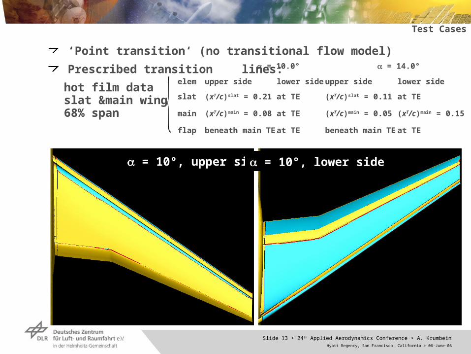
‘Point transition‘ (no transitional flow model)
Prescribed transition lines:
hot film data slat &main wing 68% span
= 10°, upper side = 10°, lower side
= 10.0° = 14.0°
elem upper side lower side upper side lower side
slat (xT/c)slat = 0.21 at TE (xT/c)slat = 0.11 at TE
main (xT/c)main = 0.08 at TE (xT/c)main = 0.05 (xT/c)main = 0.15
flap beneath main TE at TE beneath main TE at TE

Slide 14 > 24th Applied Aerodynamics Conference > A. KrumbeinHyatt Regency, San Francisco, California > 06-June-06
Results
= 10°, upper sideprescribed
= 10°, upper sidepredicted
= 10.0°, upper side: laminar surface regions
Computational Results

Slide 15 > 24th Applied Aerodynamics Conference > A. KrumbeinHyatt Regency, San Francisco, California > 06-June-06
Results
= 10°, lower sideprescribed
= 10°, lower sidepredicted
= 10.0°, lower side: laminar surface regions

Slide 16 > 24th Applied Aerodynamics Conference > A. KrumbeinHyatt Regency, San Francisco, California > 06-June-06
Results
= 14.0°, upper side: laminar surface regions
= 14°, upper sideprescribed
= 14°, upper sidepredicted

Slide 17 > 24th Applied Aerodynamics Conference > A. KrumbeinHyatt Regency, San Francisco, California > 06-June-06
Results
= 14.0°: laminar surface regions & transition labels
TSTS
TS
TS
TS
= 14°, upper sidepredicted
CF
CF
CF
CF
= 14°, lower sidepredicted

Slide 18 > 24th Applied Aerodynamics Conference > A. KrumbeinHyatt Regency, San Francisco, California > 06-June-06
Results
Comparison ofprescribed & predicted transition lines
= 10°, upper sidepredicted
= 14°, upper sidepredicted
section of the hot films
calibration point for NTS

Slide 19 > 24th Applied Aerodynamics Conference > A. KrumbeinHyatt Regency, San Francisco, California > 06-June-06
ResultsComparison ofcp-distributions: = 0.20, 0.38, 0.66, 0.88
= 14.0°

Slide 20 > 24th Applied Aerodynamics Conference > A. KrumbeinHyatt Regency, San Francisco, California > 06-June-06
Conclusion
Conclusion The complete coupled system (RANS solver & transition prediction module) was succesfully applied to a complex aircraft configuration of industrial relevance WB with 3-element high-lift system
The predicted transition lines are reasonable and quite different from estimated ones based on an experiment
But, they are of preliminary character:Transition prediction module does not yet cover all transition mechanisms which can occur in 3d high-lift flows
Transition inside laminar separation bubbles, attachment line transition & by-pass trasition can not be detected
More validation on complex configurations necessary
It seems to be evident that transition inside laminar separation bubbles is of high importance
It was shown that a fully turbulent simulation or an estimation of the transition lines can result in significant deficiencies

Slide 21 > 24th Applied Aerodynamics Conference > A. KrumbeinHyatt Regency, San Francisco, California > 06-June-06
Further comparisons for the current tast cases:Skin friction lines vs. flow visualizations
Global coeffcients: lift & drag
More validation cases, e.g. DLR F5 wing → transonic test case & other more complex test cases
Empirical criteria for: - transition inside laminar separation bubbles - attachment line transition - bypass transition
Incorporation of a fully automated linear stability code into the transition prediction module → alternative for database methods
Consideration of relaminarization
Acknowledgments: Work carried out in EUROLIFT II project, partly funded by EU Computational grid provided by Airbus Germany
Outlook
Outlook