hy120 beam shaper – principle, adjustments & selection · hy120 beam shaper – principle,...
TRANSCRIPT

Optec Laser Micromachining!"!Technote!RA27!www.optec.be!
HY120 Beam Shaper – principle, adjustments & selection !HY120 was principally designed for excimer lasers though has been successfully use with some other laser types. With the standard uncoated UVFS optics it is wavelength tolerant from the UV though to near IR, special versions with ZnSe optics have been built for CO2-TEA lasers at 9-11µm. A well-behaved excimer laser has a typical beam profile often described as quasi-Gaussian in the short, low divergence axis, whereas the long axis generally has a flattish top >> However, most applications call for a uniform intensity beam. Theory
Optec HY120 Beam Shaper works by employing specially cut cylindrical lens segments to recover the ‘lost’ energy from the low energy ‘wings’ of the raw beam and using it cleverly to compensate for the fall in energy density away from the centre of the distribution. Schematically, we have:-
In a ray tracing,- here of just half the beam,- the light blue rays (coming from the left) are those which pass through no optics, the darker blue ones are those intercepted by the lens element, brought to a line focus and then added to the main beam. Profiles in different locations are shown in red, beam spots with single axis HY in blue:-

Practice Here we compare directly, beam profiles at a mask with Optec logo, and ablation results on PI using a standard Optec excimer workstation. First without the Beam Shaper:-
… showing incomplete machining in the area corresponding to the reduction in e.d. towards the half power point of the beam. Simply inserting the HY120 at the correct position upstream of the mask leads to a dramatic improvement in both profile & results; there was no other change on the system.
We should make no apology for these results & pictures being over 25 years old at the time of writing ; that is for how long Optec HY120 Beam Shapers have been providing a low cost pulse energy upgrade to any excimer laser ! A Beam Shaper can be used to maximize useable energy in new or old lasers, and with periodic adjustment to maintain top performance from ageing lasers as profile deteriorates due to electrode erosion. A tribute to its performance, the HY120 has been copied, but never bettered ;- Use Your Photons ! Fully Adjustable In principle the elements are inserted to the nominal 50% power point of each edge of the beam, though the exact optimum insertion depends on the raw beam profile, and can be precisely controlled individually for each of the 4 elements, using the micrometer screws. The profile also evolves with distance downstream from the device, leading to the concept of working distance. Overleaf are shown the typical range of (short axis) profiles generated with different insertion degrees and at different distance from the HY120. The centre plot (red contour) is at the optimal insertion & working distance. Rows are at w.d. -20%, -10%, 0%, +10%, +20% w.r.t. the optimum, to illustrate the range of profiles generally observed.

Inserted 10% too much 50% power point Inserted 10% too little
! ! ! ! !
! ! ! ! !
! ! ! ! !
! ! ! ! !
! !! ! ! ! !!N.B. In general, navigating in the lower left area of this parameter field can still produce acceptable profiles, over-insertion of the elements leads to smaller beams with higher energy density, obtained at greater than nominal working distance. This applies only to the short quasi-Guassian contour, is much less true of the more elongated distribution of a typical long axis profile. With careful control over the degree of insertion of the lens elements, and exact distance of the working plane, one can trim the final profile very finely, and cater for a very wide variety of beam shapes, including quite highly asymmetric. It is also possible to generate unusual beam profiles which can be useful in specific processing applications >
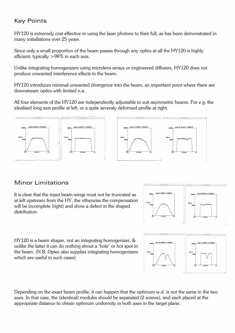
Key Points HY120 is extremely cost effective in using the laser photons to their full, as has been demonstrated in many installations over 25 years. Since only a small proportion of the beam passes through any optics at all the HY120 is highly efficient; typically >98% in each axis. Unlike integrating homogenizers using microlens arrays or engineered diffusers, HY120 does not produce unwanted interference effects in the beam. HY120 introduces minimal unwanted divergence into the beam, an important point where there are downstream optics with limited n.a. All four elements of the HY120 are independently adjustable to suit asymmetric beams. For e.g. the idealised long axis profile at left, or a quite severaly deformed profile at right.
Minor Limitations It is clear that the input beam wings must not be truncated as at left upstream from the HY, the otherwise the compensation will be incomplete (right) and show a defect in the shaped distribution. HY120 is a beam shaper, not an integrating homogenizer, & unlike the latter it can do nothing about a ‘hole’ or hot spot in the beam. (N.B. Optec also supplies integrating homogenizers which are useful in such cases) Depending on the exact beam profile, it can happen that the optimum w.d. is not the same in the two axes. In that case, the (identical) modules should be separated (2 screws), and each placed at the appropriate distance to obtain optimum uniformity in both axes in the target plane.
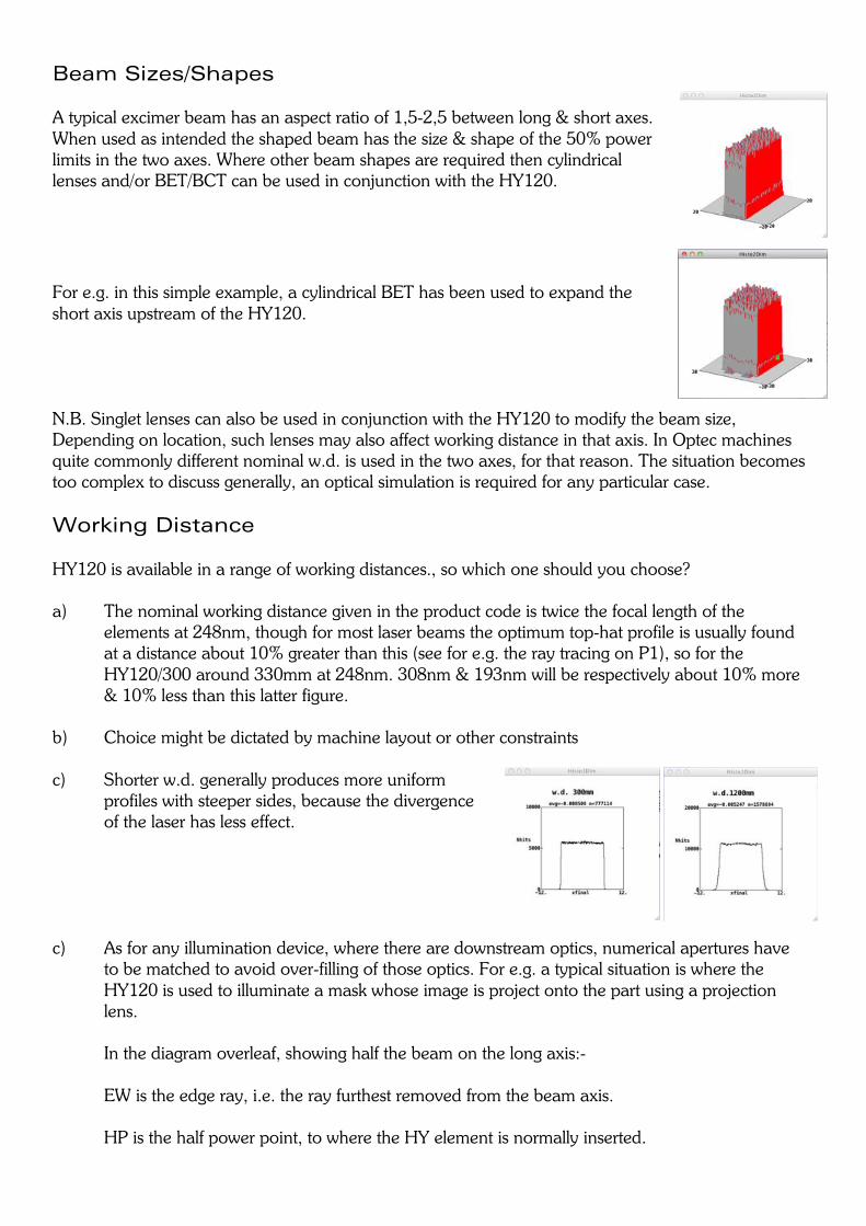
Beam Sizes/Shapes A typical excimer beam has an aspect ratio of 1,5-2,5 between long & short axes. When used as intended the shaped beam has the size & shape of the 50% power limits in the two axes. Where other beam shapes are required then cylindrical lenses and/or BET/BCT can be used in conjunction with the HY120.
For e.g. in this simple example, a cylindrical BET has been used to expand the short axis upstream of the HY120. N.B. Singlet lenses can also be used in conjunction with the HY120 to modify the beam size, Depending on location, such lenses may also affect working distance in that axis. In Optec machines quite commonly different nominal w.d. is used in the two axes, for that reason. The situation becomes too complex to discuss generally, an optical simulation is required for any particular case. Working Distance HY120 is available in a range of working distances., so which one should you choose? a) The nominal working distance given in the product code is twice the focal length of the
elements at 248nm, though for most laser beams the optimum top-hat profile is usually found at a distance about 10% greater than this (see for e.g. the ray tracing on P1), so for the HY120/300 around 330mm at 248nm. 308nm & 193nm will be respectively about 10% more & 10% less than this latter figure.
b) Choice might be dictated by machine layout or other constraints c) Shorter w.d. generally produces more uniform
profiles with steeper sides, because the divergence of the laser has less effect.
c) As for any illumination device, where there are downstream optics, numerical apertures have
to be matched to avoid over-filling of those optics. For e.g. a typical situation is where the HY120 is used to illuminate a mask whose image is project onto the part using a projection lens.
In the diagram overleaf, showing half the beam on the long axis:- EW is the edge ray, i.e. the ray furthest removed from the beam axis. HP is the half power point, to where the HY element is normally inserted.
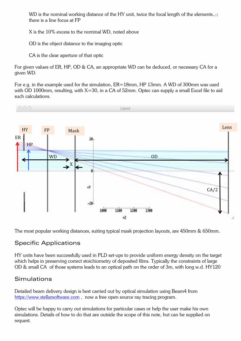
WD is the nominal working distance of the HY unit, twice the focal length of the elements.,-; there is a line focus at FP X is the 10% excess to the nominal WD, noted above OD is the object distance to the imaging optic CA is the clear aperture of that optic
For given values of ER, HP, OD & CA, an appropriate WD can be deduced, or necessary CA for a given WD. For e.g. in the example used for the simulation, ER=18mm, HP 13mm. A WD of 300mm was used with OD 1000mm, resulting, with X=30, in a CA of 52mm. Optec can supply a small Excel file to aid such calculations.
The most popular working distances, suiting typical mask projection layouts, are 450mm & 650mm. Specific Applications HY units have been successfully used in PLD set-ups to provide uniform energy density on the target which helps in preserving correct stoichiometry of deposited films. Typically the constraints of large OD & small CA of those systems leads to an optical path on the order of 3m, with long w.d. HY120 Simulations Detailed beam delivery design is best carried out by optical simulation using Beam4 from https://www.stellarsoftware.com , now a free open source ray tracing program. Optec will be happy to carry out simulations for particular cases or help the user make his own simulations. Details of how to do that are outside the scope of this note, but can be supplied on request. !
HY! Mask! Lens!FP!ER!
HP!
WD! OD!X!
CA/2!