hx-ep series digital output - pm · pdf file1. supplemental data section located at end of hx...
TRANSCRIPT

4175 SW Research Way, Corvallis, Oregon 97333 U.S.A. | Tel: 541-757-3158 | Fax: 541-757-0858 | Email: [email protected]
FOOTNOTES TO SPECIFICATIONS1. Supplemental Data section located at end of HX Series pages.2. The resolution shown is a calculated number based upon the capstan diameter, wire rope diameter and line count of the encoding device. The tolerance on the resolution accounts for resolutional differences from unit to unit due to manufacturing tolerances on the capstan and wire rope. In practice, the output count in a given unit of travel is an integer.
HX-EP SERIESDIGITAL OUTPUT
Utilizing an incremental encoder as the sensor, the UniMeasure HX-EP series position transducer provides a two channel square wave current sinking output signal in quadrature. The standard output is a single-ended TTL compatible square. The resolution values shown in the specifications table indicate resolution for times 1 counting mode where a count is registered for one up transition in channel A. With interface electronics capable of times 2 or times 4 counting mode, a true resolutional increase of 2 or 4 may be obtained. For example, the HX-EP-50 has a resolution of approximately .004" per count in times 1 counting mode whereas the resolution is approximately .001" per count in times 4 counting mode. The actual resolution of a HX-EP transducer differs from unit to unit because of tolerances associated with the wire rope diameter and the capstan upon which the wire rope winds. The nylon jacketed wire rope option will have the effect of slightly reducing the resolution. Linearity and repeatability remain independent of resolu-tion. In applications where the output count is interpreted as a percentage of total travel, resolutional differences from unit to unit are not critical. However, in applications where the digital output is to be interfaced to a digital display to give an output in engineering units, the calibration constant supplied with the transducer may be used to calculate a suitable scale multiplier to produce the correct engineering units. Alternative outputs shown in the Electrical Outputs table below are available to facilitate interfacing to a variety of different types of equipment.
GENERAL Connector .................................................. MS3102E-14S-6P Mating Connector ...................................... MS3106E-14S-6S Available Measurement Ranges ................ See Supplemental Data[1], Table 12PERFORMANCE Linearity ..................................................... ±0.03% Full Scale Repeatability ............................................. ±0.015% Full Scale Resolution ................................................. See Table 9ENVIRONMENTAL Operating temperature .............................. -20oC to +95oC Storage temperature .................................. -40oC to +100oC Shock ........................................................ 50 G's for 11 ms Duration Vibration .................................................... 15 G’s 0.1 ms max. Shock ........................................................ 50 G’s 0.1 ms max.INGRESS PROTECTION (Exclusive of Wire Rope Area) Standard .................................................... NEMA 4 (IP-65) Optional ..................................................... NEMA 6 (IP-68)ELECTRICAL Input Voltage .............................................. +5 VDC ±5% or 8-28 VDC Input Current ............................................. 125 mA Maximum Output ....................................................... Two channel TTL square wave Phase Quadrature ..................................... 90o±20o
SPECIFICATIONS
TABLE 9–RESOLUTION
MODEL RANGE RESOLUTION[2] RESOLUTIONTOLERANCE[2]
inch metric counts/inch counts/mmHX-EP-10 10 250 mm 500.0 19.69 ±0.30%HX-EP-25 25 640 mm 250.0 9.84 ±0.20%HX-EP-50 50 1250 mm 250.0 9.84 ±0.20%HX-EP-60 60 1.5 m 205.8 8.10 ±0.20%HX-EP-80 80 2.0 m 155.2 6.11 ±0.20%HX-EP-100 100 2.5 m 82.9 3.26 ±0.20%
ALL RANGESGREATER THAN 100” 100 2.5 m 82.9 3.26 ±0.20%
ELECTRICAL OUTPUT
For electrical output description, waveform and wiring, See Standard Series Supplemental Data, TABLE 8.
MODEL NUMBER CONFIGURATION
Basic configuration (for all ranges)
HX-EP-50-S10-N10-1BC
WIRE ROPES ...... Stainless Steel
(See Supplemental Data, Table 12)
N ...... Ø.018 (0,45 mm)Nylon Jacketed Stainless SteelRanges to 80” (2m) only. (formerly NJC)
J....... Ø.037 (0,94 mm)Nylon Jacketed Stainless SteelRanges 100” (2.5m) to 500” (12.7m) only.
WIRE ROPE TENSION1.............Standard2.............Reduced (Ranges to 80” only)
WIRE ROPE EXIT DIRECTIONU se Number designators shown
Table 12
RANGESelect Measurement Range From Supplemental Data, Table 12 on Page 38, Insert Corresponding Measurement Range Designator
ELECTRICAL OUTPUT10 .........5 VDC Standard 2 Channel, TTL11 .........5 VDC Standard 2 Channel, TTL with Index30.........5 VDC Push-Pull Differential Line Drive31.........5 VDC Push-Pull Differential Line Drive with Index*50.........8 to 28 VDC Current Sinking 2 Channel51.........8 to 28 VDC Current Sinking 2 Channel with Index 70.........8 to 28 VDC Push-Pull Differential Line Drive71.........8 to 28 VDC Push-Pull Differential Line Drive with Index**Options 31 and 71, only available with NEMA 4 (IP-65)configuration. No electrical cable available
For Description See Supplemental Data, TABLE 8
IP-65 (NEMA 4): Transducer equipped with body mounted connector and with or without mating connector.
Mating connector with electrical cable available separately as part number 10119-xM where ‘x’ is length of electrical cable in meters.
IP-68 (NEMA 6): Transducer equipped with bulkhead fitting and length of electrical cable. Remote end
of electrical cable may be outfitted with water proof connector. Mating connector with electrical cable available separately as part number 10424-xM where ‘x’ is length of electrical cable in meters.
NOTES FOR OPTION BOXES 7 , 8, and 9
IP-65–NEMA 4 CONNECTORB ............ 6 Pin 3102E Body Mounted Connector
IP-68–NEMA 6 ELECTRICAL CABLEP ............ Bulkhead Fitting w/ 0.3m (12”) Electrical Cable
3............. Bulkhead Fitting w/ 3m (10’) Electrical Cable4............. Bulkhead Fitting w/ 4m (13.5’) Electrical Cable5............. Bulkhead Fitting w/ 5m (16.5’) Electrical Cable6............. Bulkhead Fitting w/ 6m (20’) Electrical Cable7 ............ Bulkhead Fitting w/ 7m (23’) Electrical Cable
IP-65–NEMA 4 MATING CONNECTORC .............IP-65 Mating Connector Included K .............IP-65 Mating Connector Omitted**Electrical cable with mating connector may be ordered separately as part number 10119-xM where ‘x’ is the length required in meters.
IP-68–NEMA 6 CABLE MOUNTED CONNECTORN ............ No connector on end of electrical cableK ............ IP-68 Cable to cable connector with
no mating connector****Electrical cable with mating connector may be ordered separately as part number 10424-xM where ‘x’ is the length required in meters. Mating connector alone unavailable.
INGRESS PROTECTION1............. IP-65 (NEMA 4)2............. IP-68 (NEMA 6) 3............. IP-68 (NEMA 6) Corrosion Resistant Construction

4175 SW Research Way, Corvallis, Oregon 97333 U.S.A. | Tel: 541-757-3158 | Fax: 541-757-0858 | Email: [email protected]
HX SERIESSUPPLEMENTAL DATA
oPtionOPTION
DESIGNATORdeScriPtion
WIRE ROPE
NReplaces standard stainless steel wire rope with Ø.018 nylon jacketed wire rope. This option increases wire rope life dramatically but may increase non-linearity by as much as ±.05% of full scale.
NYLON JACKETED WIRE ROPE RANGES TO 80” ONLY
NYLON JACKETED WIRE ROPE RANGES 100" TO 500" ONLY J Replaces standard stainless steel wire rope with Ø.037 nylon
jacketed wire rope.
WIRE ROPE EXIT DIRECTION
1, 2, 3 RANGE “A” “B” “C”2”, 10” 1.12 (28.4) 1.79 (45.5) 1.21 (30.7)3”, 15”, 30” .96(24.4) 1.95 (49.5) 1.37 (34.8)4”, 20”, 40” .80 (20.3) 2.11 (53.6) 1.53 (38.9)5”, 25”, 50” .64 (16.3) 2.27 (57.7) 1.69 (42.9)6”, 60” .49 (12.4) 2.42 (61.5) 1.84 (46.7)80” .25 (6.4) 2.66 (67.6) 2.08 (52.8)
(dimensions in brackets are millimeters)
ALTERNATE WIRE ROPE EXIT RANGES TO 80” (2.0 m)
ALTERNATE WIRE ROPE EXIT RANGES 100” (2.5 m) and GREATER 1, 2, 3
(dimensions in brackets are millimeters)
POTENTIOMETER VALUE
2, 3, 4
Non-standard potentiometer linearity is as follows:
range LINEARITY 5" and Below ±1.00% of full scale10" to 25" ±0.50% of full scale30" and above ±0.25% of full scale
Note: This option is subject to potentiometer availability.
NON-STANDARD POTENTIOMETER APPLIES TO HX-PA & HX-VPA ONLY
ELECTRICAL OUTPUT POLARITYr
Output is at a maximum when wire rope is fully retracted. Output decreases as wire rope is extended. Does not apply to velocity signal.REVERSED OUTPUT
INGRESS PROTECTION
2
Connector is replaced with a bulkhead fitting and a designated length of urethane jacketed, shielded, twisted pair cable. Retraction mechanism and electrical components are sealed to NEMA 6, IP-68 capability.
NEMA 6, IP-68 CAPABILITY
CORROSION RESISTANTCONSTRUCTION 3
All external anodized aluminum parts of transducer are replaced with stainless steel and corrosion resistant plastic. Transducer is sealed to NEMA 6, IP-68 capability. Urethane jacketed, shielded, twisted pair cable exits unit. No connector on unit.
OPTION DESCRIPTIONS

4175 SW Research Way, Corvallis, Oregon 97333 U.S.A. | Tel: 541-757-3158 | Fax: 541-757-0858 | Email: [email protected]
ADDITIONAL OPTIONS
HX SERIESSUPPLEMENTAL DATA
TABLE 8
EP, HX-EP SERIES OPTIONAL ELECTRICAL OUTPUTS
OPTION OUTPUT DESCRIPTION OUTPUT STAGE WAVEFORM CONNECTOR WIRING
10 5 VDC Current Sinking5 VDC TTL compatible open collector current sinking output. Two channels with optional index channel available. 11 is same as Option 10 but adds the index (Z) channel.
Z information applies to Options 11 and 51 only.
Z information applies to 11 and 51 options only.
11
50 8 to 28 VDC Current SinkingCurrent sinking output with 10KΩ internal pullup resistors 8 to 28 VDC input voltage. 51 is same as Option 50 but adds the index (Z) channel.51
30 5 VDC Push-Pull Differential Line DrivePush-Pull, current sourcing and current sinking output. 5 VDC input voltage. Output is compliant with requirements of TIA/EIA-422-B. 31 is same as Option 30 but adds the index (Z) channel
Z & Z information applies to Options 31 and 71 only.
Z & Z information applies to 31 and 71 options only.
31
70 8 to 28 VDC Push-Pull Differential Line DrivePush-Pull, current sourcing and current sinking output. 8 to 28 VDC input voltage. 71 is same as Option 70 but adds the index (Z) channel.71

4175 SW Research Way, Corvallis, Oregon 97333 U.S.A. | Tel: 541-757-3158 | Fax: 541-757-0858 | Email: [email protected]
HX SERIES
AVAILABLE MEASUREMENT RANGES .... See Table 12CONSTRUCTION Ranges 80" (2 m) and under ...................... Anodized Aluminum Mounting Base Stainless Steel & Anodized Aluminum Housing Ranges 100" (2.5 m) and greater ............... Stainless Steel Mounting Base
High Impact, Corrosion Resistant Thermoplastic Housings
Wire Rope Tension...................................... See Table 12 Wire Rope Diameter ................................... See Table 12 Weight ........................................................ See Table 12 Connector ................................................... MS3102A-14S-6P Mating Connector ....................................... MS3106E-14S-6S Optional NEMA 6 Capability ....................... Bulkhead fitting with shielded twisted pair cable
Life[1]
Ranges 2” to 6” ........................................... 5,000,000 full stroke cycles Ranges 10” to 25” ....................................... 500,000 full stroke cycles Ranges 30” to 400” ..................................... 250,000 full stroke cycles Ranges 500” to 2000” ................................. 200x106 lineal inches
Check mark indicates available measurement range
HX-PAHX-PB
HX-P420HX-P510
(in) (mm)
Product PhotoAPPLICABLE SERIES
HX-EPHX-V
HX-VP
(oz) (N)
WIRE ROPETENSION
(NOMINAL)
Use value from this column to indicate over-all measurement range
(in) (mm) (lb) (Kg)
WIRE ROPEDIAMETER
TRANSDUCERWEIGHT
TABLE 12MEASUREMENT
RANGEDESIGNATOR
STANDARD MEASUREMENT
RANGES
2 2 50 4 - 4 34 9.4 .016 0.4 2 0.9 3 3 75 4 - 4 24 6.7 .016 0.4 2 0.9 4 4 100 4 - 4 24 6.7 .016 0.4 2 0.9 5 5 125 4 - 4 19 5.3 .016 0.4 2 0.9 6 6 150 4 - 4 24 6.7 .016 0.4 2 0.9 10 10 250 4 4 4 34 9.4 .016 0.4 2 0.9 15 15 390 4 - 4 24 6.7 .016 0.4 2 0.9 20 20 500 4 - 4 24 6.7 .016 0.4 2 0.9 25 25 640 4 4 4 19 5.3 .016 0.4 2 0.9 30 30 750 4 - 4 24 6.7 .016 0.4 2 0.9 40 40 1000 4 - 4 24 6.7 .016 0.4 2 0.9 50 50 1250 4 4 4 19 5.3 .016 0.4 2 0.9 60 60 1500 4 4 4 24 6.7 .016 0.4 2 0.9 80 80 2.0m 4 4 4 21 5.8 .016 0.4 2 0.9 100 100 2.5m 4 4 4 36 10.0 .024 0.6 6.8 3.1 120 120 3.0m 4 4 4 36 10.0 .024 0.6 6.8 3.1 150 150 3.8m 4 4 4 36 10.0 .024 0.6 6.8 3.1 200 200 5.0m 4 4 4 36 10.0 .024 0.6 6.8 3.1 250 250 6.3m 4 4 4 36 10.0 .024 0.6 6.8 3.1 300 300 7.5m 4 4 4 36 10.0 .024 0.6 6.8 3.1 350 350 8.8m 4 4 4 36 10.0 .024 0.6 6.8 3.1 400 400 10.0m 4 4 4 36 10.0 .024 0.6 6.8 3.1
500 500 12.5m 4 4 4 36 10.0 .024 0.6 8.6 3.9 600 600 15.2m 4 4 4 36 10.0 .024 0.6 8.6 3.9 800 800 20.3m 4 4 4 36 10.0 .024 0.6 8.6 3.9 1000 1000 25.4m 4 4 - 36 10.0 .024 0.6 12.0 5.4 1200 1200 30.4m 4 4 - 36 10.0 .024 0.6 12.3 5.6
1600 1600 40.6m 4 4 - 36 10.0 .024 0.6 14.1 6.4
1800 1800 45.7m 4 4 - 36 10.0 .021 0.6 15.9 7.2 2000 2000 50.8m 4 4 - 36 10.0 .021 0.5 16.3 7.4
SUPPLEMENTAL DATA
MECHANICAL SPECIFICATIONS
TYPICAL HX MOUNTING BOLTSNOTES:1. With 1K ohm potentiometer, wire rope misalignment 2° maximum at full stroke, relatively dust free environment, nylon jacketed wire rope on units with ranges 80” and less.
Specifications subject to change without notice
4175 SW Research Way, Corvallis, Oregon 97333 U.S.A. | Tel: 541-757-3158 | Fax: 541-757-0858 | Email: [email protected]
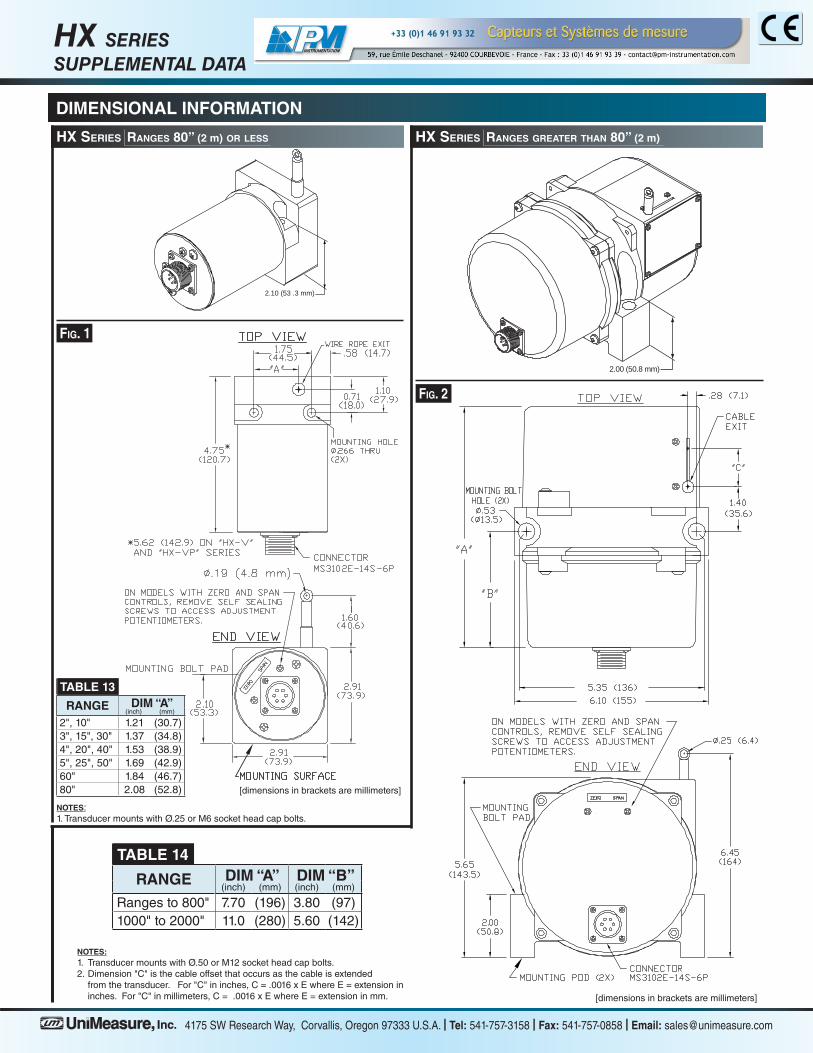
NOTES:1. Transducer mounts with Ø.50 or M12 socket head cap bolts.2. Dimension "C" is the cable offset that occurs as the cable is extended from the transducer. For "C" in inches, C = .0016 x E where E = extension in inches. For "C" in millimeters, C = .0016 x E where E = extension in mm.
NOTES:1. Transducer mounts with Ø.25 or M6 socket head cap bolts.
2.10 (53 .3 mm)
2.00 (50.8 mm)
HX SERIESSUPPLEMENTAL DATA
DIMENSIONAL INFORMATION
HX SerieS rangeS 80” (2 m) or LeSS HX SerieS rangeS greater tHan 80” (2 m)
TABLE 13
RANGE diM “a”(inch) (mm)
2", 10" 1.21 (30.7)3", 15", 30" 1.37 (34.8)4", 20", 40" 1.53 (38.9)5", 25", 50" 1.69 (42.9)60" 1.84 (46.7)80" 2.08 (52.8) [dimensions in brackets are millimeters]
TABLE 14
RANGE diM “a” diM “b”(inch) (mm) (inch) (mm)
Ranges to 800" 7.70 (196) 3.80 (97)1000" to 2000" 11.0 (280) 5.60 (142)
[dimensions in brackets are millimeters]