h.w.w.s. m.f. runnion water treatment plant raw water ......m.f. runnion water treatment plant raw...
TRANSCRIPT

City of Harlingen H.W.W.S. M.F. Runnion Water Treatment Plant
Raw Water & High Service VFD’S And Upgrades
RFP# 16505
Due: May 24, 2017 At 2:00 PM

Texas Engineering Firm F#15998
TOC - I Ethos Engineering, 119 West Van Buren, Suite 101, Harlingen, TX 78550
TABLE OF CONTENTS MEP SPECIFICATIONS FOR H.W.W.S. – M.F. RUNNION WATER TREATMENT PLANT RAW WATER & HIGH SERVICE VFD’S AND UPGRADES HARLINGEN, TEXAS
May 5, 2017
DIVISION 0: PROCUREMENT AND CONTRACTING REQUIREMENTS 000100 Request for Proposal
000141 Contractor’s Qualification A305
000200 Instructions to Bidders A701
000210 Supplementary Instructions to Bidders
HWWS Requirements
Instructions to Respondents
For 1295 Certificate of Interested Parties
Disclosure of Conflict of Interest
W-9 Form
W-8 Form
Evaluation Criteria
Proposal Evaluation Form
000400 Proposal Form
000500 Vendor Agreement
000610 Bid Bond AIA - 310
000620 Performance and Payment Bonds AIA – 312
000820 Schedule of Values

TOC - II Ethos Engineering, 119 West Van Buren, Suite 101, Harlingen, TX 78550
DIVISION 1: GENERAL REQUIREMENTS
011000 Summary
012100 Allowances
012900 Payment Procedures
013100 Project Management and Coordination
013300 Submittal Procedures
014200 References
016000 Product Requirements
017300 Execution
017320 Selective Demolition
017400 Guarantees
017700 Closeout Procedures
017823 Operation and Maintenance Data
017900 Demonstration and Training
DIVISION 26: ELECTRICAL
260010 Summary of Electrical Work
260519 Low-Voltage Electrical Power Conductors and Cables
260526 Grounding and Bonding for Electrical Systems
260529 Hangers and Supports for Electrical Systems
260533 Raceways and Boxes for Electrical Systems
260544 Sleeves and Sleeves Seals for Electrical Raceways and Cabling
260553 Identification for Electrical Systems
262923 Variable Frequency Motor Controllers
265116 Interior Lighting
265219 Emergency and Exit Lighting

TOC - III Ethos Engineering, 119 West Van Buren, Suite 101, Harlingen, TX 78550
DRAWINGS COVER Cover Sheet E-1 Electrical Site Plan
E-2 Electrical Details & Symbols Legend
E-3 Chlorine/Chemical Day Tank & Raw Water Pump Buildings Electrical Plan
E-4 High Service Pump Building Electrical Plan
E-5 Electrical Riser Diagram & Schedules

REQUEST FOR PROPOSALS
Date: May 4, 2017
Dear Respondent:
The Harlingen Waterworks System (HWWS) invites you to submit sealed Proposals for M.F. Runnion Water Treatment Plant Raw Water & High Service Variable Frequency Devices (VFDs) and Upgrades, RFP # 16505. Detailed specifications and Proposal forms may be obtained at HWWS Purchasing Agent’s Office at 114 North L St., Harlingen, TX for a nominal non-refundable fee or on the Harlingen Waterworks System Website at www.hwws.com.
The Harlingen Waterworks System will receive sealed Proposals addressed to the Purchasing Agents Office at 114 North L Street, Harlingen TX 78550 until 2:00 P.M., on WEDNESDAY, MAY 24, 2017. No late submittals will be accepted. Proposal must be submitted in a sealed envelope clearly marked with the project name and RFP number. Each proposal which is not signed by the offeror or an authorized representative of the offeror shall be rejected. The submittals will be publicly opened and the names of those submitting proposals will be read aloud. All Respondents are invited to attend the opening. A Pre-Proposal Conference and Walkthrough is scheduled for Wednesday, May 17, 2017 at 10:00 a.m. at the jobsite 2525 Dixieland Rd, Harlingen, Texas.
We request that you carefully read the “Instructions to Respondents” which are enclosed. Questions concerning this Proposals must be made in writing and directed via e-mail, or fax to:
Name: Danielle Bates Title: Purchasing Agent E-Mail: [email protected] Fax: (956) 440-6590
The Harlingen Waterworks System reserves the right to refuse and reject any or all submittals, waive any or all formalities or technicalities, hold submittals for a period of 60 days without taking action, and accept the submittals to be the best and most advantageous to the Harlingen Waterworks System. Sincerely, Danielle Bates Purchasing Agent


SECTION 000210 - SUPPLEMENTARY INSTRUCTIONS TO BIDDERS
SUPPLEMENTARY INSTRUCTIONS TO BIDDERS 000210 - 1
The following supplements contain changes and additions to the Instructions to Bidders, AIA Document A701, 1997 Edition. The portions of the Instructions to Bidders not modified, supplemented or deleted by these Supplementary Instructions to Bidders shall remain in effect. As appropriate, for purposes of this Request for Competitive Sealed Bids, the term “Proposal” shall mean “Bid”, the term “Offeror” shall mean “Bidder”, and the term “Architect” shall mean “Engineer” wherever they appear in the Contract Documents.
ARTICLE 3 -- BIDDING DOCUMENTS
3.4 ADDENDA Delete subparagraph 3.4.3 in its entirety.
ARTICLE 4 -- BIDDING PROCEDURES
Add paragraph 4.5 as follows:
4.5 OTHER DOCUMENTS TO BE SUBMITTED WITH BID 4.5.1 A fully executed Affidavits. Refer to Document. 4.5.2 A fully executed Felony Conviction Notification form. Refer to Document. 4.5.3 A fully executed Affidavit of Non-Collusion. Refer to Document.
ARTICLE 7 -- PERFORMANCE BOND AND PAYMENT BOND
7.1 BOND REQUIREMENTS At subparagraph 7.1.1, add the following clause at the end of the last sentence: “except as required otherwise, refer to Supplementary Conditions, Article 11.5.” Delete subparagraph 7.1.3 in its entirety, and replace it with the following: 7.1.3 Bonding Companies (Sureties) shall comply with the requirements of Article 11 of the General
Conditions and Supplementary Conditions.
Add Article 9 as follows:
ARTICLE 9 -- ADDITIONAL INFORMATION AND INSTRUCTIONS
9.1 SALES TAX 9.1.1 The Owner is exempt from all Sales Tax, refer to Supplementary Conditions, Article 3.
9.2 WAGE RATES 9.2.1 The Owner has adopted a schedule of minimum wage rates for employees used in the construc-tion of this project, refer to Supplementary Conditions, Article 3.

SECTION 000210 - SUPPLEMENTARY INSTRUCTIONS TO BIDDERS
SUPPLEMENTARY INSTRUCTIONS TO BIDDERS 000210 - 2
9.3 HAZARDOUS MATERIALS 9.3.1 The use of any construction process or the installation of any materials containing the following is strictly prohibited on this project
.1 Asbestos
.2 Lead
.3 P.C.B. (Polychloride Biphenyls)
.4 Refrigerants R-11, R-12, R-113, R-114, R-500 and R-502 9.3.2 Prior to submitting a Proposal, each Offeror shall notify the Architect in writing of any materials or systems in the Bidding Documents which he has reason to believe contain any of the above listed items.
9.4 TOBACCO FREE FACILITY 9.4.1 The Owner has designated their facility as a tobacco free facility; therefore, the use of any tobac-
co will not be permitted anywhere on the project site at any time.
Add Article 10 as follows:
ARTICLE 10 – HARLINGEN WATER WORKS SYSTEMS GENERAL TERMS AND CONDITIONS
10.1 The Harlingen Water Works Systems is soliciting proposals on the merchandise, supplies, and/or
equipment set forth in this proposal package. a. Specifications, as written meet specific requirements. Submittals (offers) different to the
original requirements must meet or exceed original proposal specifications to be considered as equivalent. It is a mandatory requirement of these specifications, in order to qualify alter-nate (equal) products to those specifically named; that, complete material/product specifica-tion-data sheets to be provided with the sealed proposal package as applicable. Failure to provide or denote this information will be sufficient grounds for disqualification. Should the proposer fail to denote his offer is for an alternate item: then, stated price will be accepted for the actual product specifically named. Resulting contracts/orders resulting from the award will be processed by a formal instrument (Purchase Order).
c. During the performance of this contract, the vendor agrees not to discriminate against any
employee or applicant for employment because of race, color, national origin, age, religion, gender, marital or veteran status, or disabled condition.
d. All contracts and agreements between merchants and HWWS shall strictly adhere to the stat-
utes as set forth in the Uniform Commercial Code as last amended in 1977 by the American Law Institute in the national Conference of Commissioners on Uniform State laws, or latest revision. Reference: Uniform Commercial Code, 1987 official text.
e. Merchandise received shall be newly manufactured merchandise. Refurbished or recondi-
tioned merchandise will not be allowed, unless specifically required in the bid. Merchandise received in this condition will be returned freight collect at the vendors’ expense. If this

SECTION 000210 - SUPPLEMENTARY INSTRUCTIONS TO BIDDERS
SUPPLEMENTARY INSTRUCTIONS TO BIDDERS 000210 - 3
problem is not corrected within ten (10) working days of notification the HWWS, under Uni-form Commercial Code, will have the right to seek remedy.
f. Fund out provision: Should, during the term of the resulting contract, funding allocations be
cut or exhausted HWWS will be held harmless for any future obligations to the said contract.
END OF SECTION 000210

INSTRUCTIONS TO RESPONDENTS SECTION I GENERAL TERMS AND CONDITIONS ADDITIONAL INFORMATION: The City of Harlingen Water Works System is requesting that all questions be routed to Danielle Bates, Purchasing Agent, at (956) 440-6560, email: [email protected]. Questions must be in writing and sent via email or fax (956) 440-6590. NON-COLLUSION: Proposers by submitting a signed proposal, certify that the accompanying proposal is not the result of, or affected by, any unlawful act of collusion with any other person or company engaged in the same line of business or commerce, or any other fraudulent act punishable under Texas or United State Law. NON-DISCRIMINATION: Proposers, during the performance of this contract, will not discriminate against any employee or applicant of employment because of race, religion, sex, national origin or disability is a bona fide occupational qualification reasonably necessary to the normal operation of the contractor. PROCESSING TIME FOR PAYMENT: Proposers are advised that a minimum of thirty (30) days is required to process invoices for payment. ELECTRONIC TRANSMISSION OF BIDS: The City of Harlingen Water Works System’s Purchasing Department will not accept telegraphic, facsimile, or electronically transmitted proposals. PROOF OF FINANCIAL AND BUSINESS CAPABILITY: Proposers must, upon request, furnish satisfactory evidence of their ability to furnish products or services in accordance with the terms and conditions of these specifications. The City of Harlingen Water Works System will make final determination as to the vendor’s ability. PROPOSER DEFAULT: The City of Harlingen Water Works System reserves the right, in case of proposer default, to procure the articles or services from other sources and hold the defaulting vendor responsible for any excess costs occasioned thereby. RESTRICTIVE OR AMBIGUOUS SPECIFICATIONS: It is the responsibility of the proposer to review the request for Proposals (RFP) packet and to notify the Purchasing Department if the specifications are formulated in a manner that would unnecessarily restrict competition. Any such protest or question regarding the specifications must be received in the Purchasing Department not less than seventy-two hours (72) prior to the time set for the opening. These requirements also apply to specifications that are ambiguous. PROPOSALS DELIVERY: City of Harlingen Water Works Systems Water Works System requires proposers, when hand delivering Proposals, to have the proposal time and date stamped by the HWWS Purchasing employee receiving it SIGNING OF PROPOSALS: To be considered all submittals must be signed. Please sign the original in blue ink. WAIVING OF INFORMALITIES: City of Harlingen Water Works System reserves the right to waive minor informalities or technicalities when it is in the best interest of the City of Harlingen Water Works System. SUBCONTRACTING: The successful proposer may not subcontract the award without the written consent of City of Harlingen Water Works System’s Board of Trustees.

SECTION II SUBMITTAL REQUIREMENTS TECHNICAL SUBMITTAL: The required contents and limitation for the preparation of the technical submittal are described in this section. Failure to provide the requested information or adhere to any state limitations will result in disqualification of the submittal. COST SUBMITTAL: Proposals are to be in a separate sealed envelope submitted with your Technical Proposal. Pricing is to be FOB Destination, Full Freight Allowed. CONTENTS: The required contents for the technical submittal are presented below in the order they should be incorporated into the submitted document. UNDERSTANDING THE PROPOSED PROJECT: This section should demonstrate that the proposer understands project needs, work required, and any local issues or concerns. Additionally, for the firm and each sub-provider, a client contract name and phone number should be included for reference purposes relating to each project submitted under qualification. This project list is limited to one (1) page in length. REQUIRED CERTIFICATION AND SUBMITTAL: This section will contain any certification and assurance as required by City of Harlingen Water Works Systems. The proposal firm should add copies of their insurance. NUMBER OF COPIES TO BE SUBMITTED: City of Harlingen Water Works Systems requires one (1) original and four (4) copies of the Technical Proposal and one (1) original of the Proposal is required. Technical Proposals should be indexed and contain the following;
1) Cover Page Listing Title of Proposal and Proposing Firms Name 2) Understanding of Scope of Services 3) Familiarity with Applicable Rules and Regulations 4) References 5) Experience with Variable Frequency Drives 6) Past Experience with HWWS 7) Quality Control 8) Failure to Perform
Proposal documents must be completed and signed, included with proposal in a separate sealed envelope, and must contain the following:
1) Proposal 2) Form 1295 completed and filed with the Texas Ethics Commission 3) Conflict of Interest Form 4) W9 or W8 Form, whichever is applicable 5) 2 Signed Originals of the Vendor Agreement

SECTION III – SELECTION AND SCHEDULES SELECTION PROCEDURES: The technical submittal shall be made according to the schedule below. Proposals are to be in a separate sealed envelope submitted with your proposal. PROPOSALS RANKING: The City of Harlingen Water Works System will rank the written Technical Proposals. After the Technical Proposals are ranked, negotiations on cost will happen, then the Water Director will recommend the selected firm to the Harlingen Water Works System Board of Trustees. NEGOTIATION PROCESS: If negotiations prove unsuccessful, the next firm will be contacted. The City of Harlingen Water Works System reserves the right to reject any and all Proposals. PROPOSALS SUBMITTED TO: City of Harlingen Water Works Systems requires one (1) original and four (4) copies of the Technical Proposal. Only one (1) original of the Proposal is required. They should be made to:
City of Harlingen Water Works Systems Purchasing Department
114 North L Street Harlingen TX 78550


Form W-9 (Rev. October 2007) Department of the Treasury
Internal Revenue Service
Request for Taxpayer Identification Number and Certification
Give form to the requester. Do not send to the IRS.
Name (as shown on your income tax return)
Business name, if different from above Address (number, street, and apt. or suite no.) City, state, and ZIP code
List account number(s) here (optional)
Part I Taxpayer Identification Number (TIN)
Enter your TIN in the appropriate box. The TIN provided must match the name given on Line 1 to avoid backup withholding. For individuals, this is your social security number (SSN). However, for a resident alien, sole proprietor, or disregarded entity, see the Part I instructions on page 3. For other entities, it is your employer identification number (EIN). If you do not have a number, see How to get a TIN on page 3. Note. If the account is in more than one name, see the chart on page 4 for guidelines on whose number to enter.
Social security number
o r Employer identification number
Part II Certification Under penalties of perjury, I certify that: 1. The number shown on this form is my correct taxpayer identification number (or I am waiting for a number to be issued to me), and 2. I am not subject to backup withholding because: (a) I am exempt from backup withholding, or (b) I have not been notified by the Internal Revenue
Service (IRS) that I am subject to backup withholding as a result of a failure to report all interest or dividends, or (c) the IRS has notified me that I am no longer subject to backup withholding, and
3. I am a U.S. citizen or other U.S. person (defined below). Certification instructions. You must cross out item 2 above if you have been notified by the IRS that you are currently subject to backup withholding because you have failed to report all interest and dividends on your tax return. For real estate transactions, item 2 does not apply. For mortgage interest paid, acquisition or abandonment of secured property, cancellation of debt, contributions to an individual retirement arrangement (IRA), and generally, payments other than interest and dividends, you are not required to sign the Certification, but you must provide
your correct TIN. See the instructions on page 4. Signature of U.S. person Date
General Instructions Section references are to the Internal Revenue Code unless otherwise noted.
Purpose of Form A person who is required to file an information return with the IRS must obtain your correct taxpayer identification number (TIN) to report, for example, income paid to you, real estate transactions, mortgage interest you paid, acquisition or abandonment of secured property, cancellation of debt, or contributions you made to an IRA.
Use Form W-9 only if you are a U.S. person (including a resident alien), to provide your correct TIN to the person requesting it (the requester) and, when applicable, to:
1. Certify that the TIN you are giving is correct (or you are waiting for a number to be issued),
2. Certify that you are not subject to backup withholding, or 3. Claim exemption from backup withholding if you are a U.S.
exempt payee. If applicable, you are also certifying that as a U.S. person, your allocable share of any partnership income from a U.S. trade or business is not subject to the withholding tax on foreign partners’ share of effectively connected income. Note. If a requester gives you a form other than Form W-9 to request your TIN, you must use the requester’s form if it is substantially similar to this Form W-9.
Definition of a U.S. person. For federal tax purposes, you are considered a U.S. person if you are: An individual who is a U.S. citizen or U.S. resident alien, A partnership, corporation, company, or association created or organized in the United States or under the laws of the United States, An estate (other than a foreign estate), or A domestic trust (as defined in Regulations section 301.7701-7). Special rules for partnerships. Partnerships that conduct a trade or business in the United States are generally required to pay a withholding tax on any foreign partners’ share of income from such business. Further, in certain cases where a Form W-9 has not been received, a partnership is required to presume that a partner is a foreign person, and pay the withholding tax. Therefore, if you are a U.S. person that is a partner in a partnership conducting a trade or business in the United States, provide Form W-9 to the partnership to establish your U.S. status and avoid withholding on your share of partnership income.
The person who gives Form W-9 to the partnership for purposes of establishing its U.S. status and avoiding withholding on its allocable share of net income from the partnership conducting a trade or business in the United States is in the following cases: The U.S. owner of a disregarded entity and not the entity,
Prin
t or t
ype
See
Spec
ific
Inst
ruct
ions
on
page
2.
E x e m p t p a y e e
Requester’s name and address (optional)
Check appropriate box: Individual/Sole proprietor Corporation Partnership Limited liability Company. Enter the tax classification (D=disregarded entity, C=corporation, P=partnership) other (see instructions)
S i g n H e r e

Sign Here
F
Signature of beneficial owner (or individual authorized to sign for beneficial owner) Date (MM-DD-YYYY)
Form W-8BEN
(Rev. February 2014)
Department of the Treasury Internal Revenue Service
Certificate of Foreign Status of Beneficial Owner for United States Tax Withholding and Reporting (Individuals)
a For use by individuals. Entities must use Form W-8BEN-E. a Information about Form W-8BEN and its separate instructions is at www.irs.gov/formw8ben.
a Give this form to the withholding agent or payer. Do not send to the IRS.
Do NOT use this form if: Instead, use Form: • You are NOT an individual ............................................................................................................................................................................. W-8BEN-E
• You are a U.S. citizen or other U.S. person, including a resident alien individual W-9
• You are a beneficial owner claiming that income is effectively connected with the conduct of trade or business within the U.S. (other than personal services) ............................................................................................................................................................................. W-8ECI
• You are a beneficial owner who is receiving compensation for personal services performed in the United States ........................................ 8233 or W-4
• A person acting as an intermediary .................................................................................................................................................................... W-8IMY
Part I Identification of Beneficial Owner (see instructions) 1 Name of individual who is the beneficial owner 2 Country of citizenship
3 Permanent residence address (street, apt. or suite no., or rural route). Do not use a P.O. box or in-care-of address.
City or town, state or province. Include postal code where appropriate. Country
4 Mailing address (if different from above)
City or town, state or province. Include postal code where appropriate. Country
5 U.S. taxpayer identification number (SSN or ITIN), if required (see instructions) 6 Foreign tax identifying number (see instructions)
7 Reference number(s) (see instructions) 8 Date of birth (MM-DD-YYYY) (see instructions)
Part II Claim of Tax Treaty Benefits (for chapter 3 purposes only) (see instructions) 9 I certify that the beneficial owner is a resident of within the meaning of the income tax treaty
between the United States and that country.
10 Special rates and conditions (if applicable—see instructions): The beneficial owner is claiming the provisions of Article of the treaty identified on line 9 above to claim a % rate of withholding on (specify type of income):
Under penalties of perjury, I declare that I have examined the information on this form and to the best of my knowledge and belief it is true, correct, and complete. I further certify under penalties of perjury that:
• I am the individual that is the beneficial owner (or am authorized to sign for the individual that is the beneficial owner) of all the income to which this form relates or am using this form to document myself as an individual that is an owner or account holder of a foreign financial institution,
• The person named on line 1 of this form is not a U.S. person, • The income to which this form relates is:
(a) not effectively connected with the conduct of a trade or business in the United States,
(b) effectively connected but is not subject to tax under an applicable income tax treaty, or
(c) the partner’s share of a partnership's effectively connected income,
• The person named on line 1 of this form is a resident of the treaty country listed on line 9 of the form (if any) within the meaning of the income tax treaty between the United States and that country, and
• For broker transactions or barter exchanges, the beneficial owner is an exempt foreign person as defined in the instructions.
Furthermore, I authorize this form to be provided to any withholding agent that has control, receipt, or custody of the income of which I am the beneficial owner or any withholding agent that can disburse or make payments of the income of which I am the beneficial owner. I agree that I will submit a new form within 30 days if any certification made on this form becomes incorrect.
OMB No. 1545-1621
Explain the reasons the beneficial owner meets the terms of the treaty article:
Part III Certification
.

Evaluation Criteria - The submittal shall include the following:
Mandatory Requirements; Each proposal shall indicate compliance with the following standards. Proposals that fail to meet these mandatory requirements will not be scored and will result in the disqualification of your proposal. Proposals that meet or exceed the mandatory requirements will be scored.
1. Understanding of Project (30)
Demonstrate an understanding of the scope of services Address the approach to complete the scope
Minimum Proposals - The submittal must reflect an understanding of the scope of services.
Preferred Proposals - The submittal addresses the approach to complete the scope and identify information to be gathered or obtained and how it will be used in addition to the Minimum Proposals above.
2. Familiarity with Applicable Rules and Regulations (10)
The submittal should indicate through past experience of the proposal firm that they possess sufficient knowledge of governmental regulations, appropriate codes, guidelines, professional standards and policies (as required).
Minimum Proposals - The submittal must contain a narrative that outlines applicable regulations, guidelines, standards and policies as they pertain to Variable Frequency Drives.
3. References from Owners of Past Performance (10)
On separate sheets provide at least three letters of references from owners of similar projects as they pertain to Variable Frequency Drives. Minimum Proposals - References submitted that are of acceptable completion of projects. Preferred Proposals - References that are from Governmental entities of projects in similar size and nature.

4. Project Experience (20)
Please provide a list of 10 projects of similar size, type, and complexity to this project. Please show name and contact information for principal representative of each project listed. Minimum Proposals – Projects of similar size, type, and complexity to this project. Preferred Proposals - Projects of Variable Frequency Drives
5. Past Experience with HWWS (5)
Please list past experience, if any, in working with HWWS on similar projects.
Minimum Proposals – None
Preferred Proposals – Past experience in working with HWWS.
6. Quality Control (15) Please explain the quality control process used during construction. Minimum – Explanation of your quality control process. Preferred Proposals – ISO Certification
7. Failure to Perform (10) Have you ever failed to totally complete a project? Have you ever failed to complete a project according to agreed upon timelines? If yes, please explain in detail. Minimum Proposals – Minimal delay in timeliness completion of projects Preferred Proposals – No failure to complete or finish in a timely manner of projects.

PROPOSALS EVALUATION FORM
Selection RIF* (Scale 0-3) Score 1. Understanding of Project (30) X ( ) = ( ) 2. Familiarity with Rules and (10) X ( ) = ( ) Regulations 3. References (10) X ( ) = ( ) 4. Project Experience (20) X ( ) = ( ) 5. Past Experience with HWWS (05) X ( ) = ( ) 6. Quality Control (15) X ( ) = ( ) 7. Failure to Perform (10) X ( ) = ( ) Total 100% Total Score _____ Proposers Company Name: Evaluator: Date: * The Relative Importance Factor (RIF) is the relative importance (or weight) of each criterion as
it relates to the particular project. The RIF is expressed as a percentage of the total importance of the project, and always totals 100%.
** Each proposal is to be evaluated with regard to the selection criteria by each committee
member, on the basis of a rating system with the following scale: 0 – Does not meet minimum Proposals. 1 – Meets minimum Proposals. 2 – Meets preferred Proposals. 3 – Exceeds preferred Proposals.

000400 – PROPOSAL FORM
Ethos Engineering 000400 - 1
PROJECT TITLE: H.W.W.S. M.F. RUNNION WATER TREATMENT PLANT RAW WATER & HIGH SERVICE VFD’S AND UPGRADES
Harlingen, TX RFQ NO: #16505 DUE DATE, TIME & PLACE: Wednesday, May 24, 2017 at 2:00 pm
Harlingen Water Works System Purchasing Department 114 North L Street Harlingen, TX 78550
1. The undersigned OFFEROR proposes and agrees, if this Proposal is accepted, to enter into an
Agreement with OWNER to provide and install Equipment and Materials as specified or indicated in the Contract Documents for the Contract Price and within the Contract Time indicated in this Proposal and in accordance with the Contract Documents.
2. OFFEROR accepts all of the terms and conditions of the Instructions to Bidders and Supplementary Instructions to Bidders. This Proposal shall remain in effect for a period of no less than thirty days after the date of Proposal opening.
3. In submitting this Proposal, OFFEROR certifies that:
(a) OFFEROR has examined copies of all the Contract Documents and of the following Addenda:
Date Number Acknowledgment (Signature Required) ______________ ______________ ______________ ______________
(b) This Proposal is genuine and not made in the interest of or on behalf of any undisclosed
person, firm or corporation and is not submitted in conformity with any agreement or rules of any group, association, organization, or corporation; OFFEROR has not directly or indirectly induced or solicited any other OFFEROR to submit a false or sham Quote; OFFEROR has not solicited or induced any person, firm or a corporation to refrain from proposing; and OFFEROR has not sought by collusion to obtain for himself any advantage over any other OFFEROR or over OWNER.
4. Project Deadlines and Penalties: This provision shall be enforced, except in the event of
inclement weather, unnecessary delay caused by OWNER or his agent, or other natural disaster or Act of God beyond Contractor's control.

000400 – PROPOSAL FORM
Ethos Engineering 000400 - 2
(a) OFFEROR agrees that the project shall achieve Substantial and Final Completion as noted on Proposal Form. In the event of failure to complete work on time, OFFEROR agrees to pay penalties in the amount of $500 per day until system is installed and operational.
(b) Offeror agrees that the project shall achieve Final Completion within 30 days after Substantial Completion. In the event of failure to achieve Final Completion, OFFEROR agrees to pay penalties in the amount of $250 per day between day 31 and day 60 after Substantial Completion.
(c) In the event of failure to achieve Final Completion, the Offeror agrees to pay penalties in the amount of $500 per day beyond day 60 after Substantial Completion.
5. Communications concerning this Proposal shall be addressed to:
Mr. Cesar A. Gonzalez, PE. 119 W. Van Buren Ave Ste 101 Harlingen, Texas 78550 Phone: (956) 230-3435; Fax: (956) 720-0830 NOTICE: In determining best value for Owner, the Owner is not restricted to considering price alone, but may consider any other factor stated in the selection criteria. It is the intent of the OWNER to award a Contract to the OFFEROR that offers the best value for the OWNER, according to the following weighted selection criteria established by the OWNER. The OWNER reserves the right to accept or reject any and/or all Proposals, to accept the Proposals that, in the OWNER’S judgment, is in the OWNER’S best interest, and to waive informalities or irregularities in a Quote received.
The OWNER will document the basis of its selection and will make the evaluations public not later than the seventh day after the date the contract is awarded. Proposals received from nonresident Offerors will be evaluated by the Owner as required by House Bill 620, 69th Legislature, 1985.

000400 – PROPOSAL FORM
Ethos Engineering 000400 - 3
OFFEROR will supply and install on-site electrical equipment and services as specified in the Project Manual dated May 5, 2017 for the following price: SUBSTANTIAL COMPLETION DATE for the project in its entirety: 180 days after Notice to Proceed (NTP). VFD’s Required Delivery Date: August 18, 2017 BASE PROPOSAL: [Proposal amount includes Allowance 1 ($25,000.00) as per specifications section 012100]. $ (number) (words) Our Proposal proposes to use the following Contractors, Subcontractors, Manufacturers, Products, Material Suppliers and Equipment Suppliers for the principal portions of the work. NAME(S) OF SUB-CONTRACTORS:
____________________________________________________________________
____________________________________________________________________
NAME(S) OF EQUIPMENT SUPPLIERS:
____________________________________________________________________
____________________________________________________________________
OTHER:
____________________________________________________________________
____________________________________________________________________
Name and Address of OFFEROR: Signature _________________________ __________________________ Name and Title

000400 – PROPOSAL FORM
Ethos Engineering 000400 - 4
_________________________ __________________________ _________________________ __________________________ Telephone ________________ Sworn to and subscribed before me this _____ day of _______________, 20___. SEAL __________________________________ Notary Public in and for the State of Texas SEAL (If Proposal is By a Corporation) ______________________________________ ______________________________________ END OF SECTION 000400

VENDOR AGREEMENT- SERVICE (9-2016)
Page 1
VENDOR AGREEMENT - SERVICE PROVIDER - Page 1
Vendor Agreement - Service Provider 1 2 THIS AGREEMENT by and between the Harlingen Waterworks System, a department of 3 the City of Harlingen, Texas, a home-rule municipality, hereinafter referred to as the 4 "WATERWORKS" and ______________________________, hereinafter referred to as 5 "Vendor," evidences the following: 6 7 1.01 PARTIES - The parties to this Agreement are: 8 9 (a) Harlingen Waterworks System, 10 a department of the City of Harlingen, Texas, 11 a home-rule municipality 12 13 134 East Van Buren Avenue Address mail to: 14 Harlingen, Texas 78550-6828 P.O. Box 1950 15 Harlingen, Texas 78551-1950 16 17 956-430-6100 18 FAX - 956-430-6111 19 20 (b) the Waterworks Authorized ______________________________________ 21 Representative: 22 956-430-________________ 23 24 (c) Vendor: ______________________________________ 25 ______________________________________ 26 ______________________________________ 27 28 956-____________________ 29 30 FAX - 956- 31 32 (d) Vendor's Authorized _____________________________________ 33 Representative: 34 956-____________________ 35 36 (e) The Vendor's complete name is required. A Vendor that is a business entity other 37 than a sole proprietorship must submit documentation to show that it is authorized to transact 38 business in the State of Texas. A business or individual doing business under an assumed name 39 must provide a copy of its Assumed Name Certificate filed with the proper authorities. 40 41 (f) A street address is required. Vendor may designate a post office box for mailing 42 purposes only. 43 44

VENDOR AGREEMENT- SERVICE (9-2016)
Page 2
VENDOR AGREEMENT - SERVICE PROVIDER - Page 2
1.02 Vendor, including the Vendor's employees and suppliers, will at all times remain 45 independent contractors and will not be considered representatives or agents of the Waterworks. 46 The method and manner of performance of Vendor's undertaking under this Agreement will be 47 under the exclusive control of Vendor. 48 49 2.01 SERVCE PURCHASED: This Agreement is for the purchase of: 50 51 _________________________________________________________________. 52 [General Description of Service] 53 54 2.02 CONTRACT DOCUMENTS - The Contract Documents are: 55 56 (a) This Agreement; 57 58 (b) The bid specifications; 59 60 (b) Vendor's bid; and 61 62 (c) Other (specify or state "none") ______________________________________. 63 64 2.03 INFORMATION FROM VENDOR - At the Waterworks' request, Vendor will 65 provide: 66 67 (a) factual information as to the existence and financial stability of 68
Vendor; and 69 70 (b) a list of other municipalities being served by Vendor. 71 72 3.01 DELIVERY DATE - The service that is the subject of this Agreement shall be 73
provided to the Waterworks as set forth in the bid specifications and as requested by the 74
Waterworks. 75
4.01 PAYMENT TO VENDOR 76 77 (a) Contract Sum - Vendor will be paid for the service provided when requested by 78 the Waterworks and provided by the Vendor. 79 80 (b) Request for Payment - Vendor will send an invoice to the Waterworks by the 10th 81 of the month following the provision of service. Submission of an invoice by Vendor is a 82 representation that the service invoiced has been provided in accord with the terms of this 83 Agreement and that the service provided meets the specifications for the type of service 84 provided. 85 86

VENDOR AGREEMENT- SERVICE (9-2016)
Page 3
VENDOR AGREEMENT - SERVICE PROVIDER - Page 3
(c) Payment by the Waterworks does not imply that the service invoiced meets 87 applicable specifications. The Waterworks reserves the right to test the service provided for 88 specification compliance. 89 90 (d) Payment will be made to Vendor no later than 30 days after approval of the 91 Vendor's invoice. 92 93 4.02 INSURANCE REQUIREMENTS - Vendor is responsible for procuring and 94 maintaining insurance coverage for the following claims: 95 96 (a) Claims for workers' compensation, which will be in the amount required by the 97 laws of the State of Texas; 98 99 (b) Claims by Vendor's employees for bodily injury, sickness, disease, or death; 100 101 (c) Claims by any person other than Vendor's employees for bodily injury, sickness, 102 disease, or death; 103 104 (d) Claims for personal injury sustained by any person as a direct or indirect result of 105 Vendor's employment of the person or sustained by any other person; 106 107 (e) Claims for damage to property (other than the work) because of injury to or 108 destruction of tangible property, including loss of use; 109 110 (f) Claims for damages for personal injury, death, or property damage resulting from 111 Vendor's use and/or maintenance of any motor vehicle; and 112 113 (g) Claims for contractual liability arising from Vendor's obligations under this 114 Agreement. 115 116 4.02 Vendor will, at its expense, purchase and maintain insurance on all of its 117 operations including the following: 118 119 (a) Comprehensive General Liability: 120 121 $1,000,000 each occurrence, $1,000,000 aggregate coverage 122 123 $1,000,000 for products and completed operations 124 125 (b) Commercial Automobile Liability 126 127 $500,000 each occurrence, $500,000 aggregate coverage 128 129 4.03 All insurance coverage will be occurrence coverage and will be with an insurance 130 carrier rated A-1 or better in the most current edition of A.M. Best's ratings guides. 131 132

VENDOR AGREEMENT- SERVICE (9-2016)
Page 4
VENDOR AGREEMENT - SERVICE PROVIDER - Page 4
4.04 Vendor will name the Waterworks and the City of Harlingen as additional 133 insureds under the general liability and automobile liability policies. 134 135 4.05 Certificates of Insurance 136 137 (a) Vendor will provide the Waterworks with Certificates of Insurance and an 138 endorsement naming the Waterworks and the City of Harlingen and additional insureds before 139 commencing work on the Project. 140 141 (b) The Certificates will provide that no coverage will be canceled, renewal refused, 142 or materially changed for the duration of this Agreement unless at least thirty days prior written 143 notice is given to the Waterworks. 144 145 4.06 Vendor will be responsible for any delay caused by failure to provide the required 146 insurance and will not be entitled to any extensions of time for any such delay. 147 148 4.07 Waiver of Subrogation - the Waterworks and Vendor waive all rights against each 149 other for damages caused by perils to the extent such perils are covered by insurance, except 150 such rights as they may have to insurance proceeds. 151 152 4.08 Waiver of Subrogation Endorsement - Vendor will require the insurance policies 153 provided pursuant to this agreement to contain a provision waiving subrogation, whether in the 154 policy or by endorsement. 155 156 5.01 WARRANTIES 157 158 (a) Vendor warrants that: 159 160 (1) Any parts or material required by the service provided to 161
the Waterworks will be paid for in accord with the terms 162 for the purchase of the service from the Vendor's provider 163 and that the service will be free of the rightful claim of any 164 provider or other third person; 165
166 (2) The service will meet or exceed the requirements of this 167
Agreement including all applicable statutes, regulations, 168 industry standards, and applicable codes; 169
170 (3) Any parts or material required by the service will be 171
merchantable with respect to goods of that kind as defined 172 by § 2.314, Texas Business & Commerce Code; and 173
174 (4) Any parts or material required by the service will be 175
suitable and fit for their intended purpose in compliance 176 with § 2.315, Texas Business & Commerce Code. 177
178

VENDOR AGREEMENT- SERVICE (9-2016)
Page 5
VENDOR AGREEMENT - SERVICE PROVIDER - Page 5
(e) Vendor warrants its service for the period and under the terms required by the 179 Contract Documents. 180 181 (f) Vendor hereby assigns to the Waterworks any warranty for any parts or material 182 included in the provided service provided by the manufacturer and/or provider of such parts or 183 material, which assignment is in addition to Vendor's warranties set forth herein. 184 185 (g) These warranties are in addition to warranties provided by Vendor. These 186 warranties prevail over any warranty disclaimer by Vendor and over any warranty by Vendor 187 inconsistent with these warranties. 188 189 5.02 WARRANTY AND SERVICE PERFORMANCE STANDARDS 190 191 (a) Vendor recognizes that: (1) the Waterworks is a public utility that operates its 192 facilities 24 hours every day; (2) the potable water and sewage treatment services provided to the 193 Waterworks' customers are critical to its customers, its operations, and its entire service area; (3) 194 a delay in providing those services can have serious consequences; and (4) the Waterworks is 195 regulated by the Texas Commission on Environmental Quality and the Texas Public Utility 196 Commission; and (4) is subject to fines and penalties for failure to comply with applicable 197 statutes and regulations. 198 199 (b) Vendor will be available to perform service no more than 24 hours after notice by 200 the Waterworks of a request for service and will meet the warranty requirements set forth herein. 201 202 (c) Service will be performed expeditiously and the equipment made ready for return 203 to service at the Waterworks' facilities within a reasonable time. Vendor will provide to the 204 Waterworks an estimate of the time required for the service to be performed and will keep the 205 Waterworks reasonably informed of the status of the service. Vendor will provide an estimate of 206 the cost of the service to be performed and will not incur any expense until expressly authorized 207 by the Waterworks. 208 209 (d) Parts and material required for the service will be new and the same or better 210 quality than the original parts and materials in the equipment serviced. 211 212 6.01 TERMINATION OR SUSPENSION 213 214 (a) The Waterworks may terminate this Agreement when, in the sole 215 opinion of the Waterworks, there has been significant noncompliance with this 216 Agreement. 217 218 (b) In lieu of termination of this Agreement, the Waterworks may, in its sole 219 discretion, elect to request that deficiencies in the service be corrected. If the Waterworks, in its 220 sole discretion, determines that deficiencies are not being corrected in a timely manner, the 221 Waterworks may terminate this Agreement. 222 223

VENDOR AGREEMENT- SERVICE (9-2016)
Page 6
VENDOR AGREEMENT - SERVICE PROVIDER - Page 6
(c) A decision by the Waterworks to terminate the Agreement is not subject to the 224 dispute resolution process set forth herein. 225 226 7.01 RESOLUTION OF DISPUTES 227 228 (a) In the event a dispute arises, except a decision by the Waterworks to terminate the 229 Agreement, delivery of service will continue to the extent possible. 230 231 (b) In the event of a dispute that cannot be resolved between the parties, the parties 232 agree to select a mediator to assist in resolving the dispute. Each party to the mediation will pay 233 an equal share of the cost of the mediation. 234 235 (c) In the event the dispute cannot be resolved by mediation, the parties may agree to 236 a binding or nonbinding arbitration or may choose to litigate the dispute. Each party to an 237 arbitration proceeding will pay an equal share of the cost. 238 239 8.01 INDEMNIFICATION 240 241 (A) VENDOR SHALL INDEMNIFY AND HOLD HARMLESS THE 242 WATERWORKS, THE CITY OF HARLINGEN, THEIR AFFILIATES, SUBSIDIARIES, 243 RELATED ENTITIES, COMMISSIONERS, OFFICERS, DIRECTORS, TRUSTEES, 244 EMPLOYEES, AGENTS, AND REPRESENTATIVES FROM AND AGAINST ANY AND 245 ALL CLAIMS, LIABILITIES, LOSSES, DAMAGES, COSTS, OR EXPENSES ARISING 246 OUT OF, RESULTING FROM, OR OCCURRING IN CONNECTION WITH THE 247 WORK TO BE PERFORMED OR MATERIALS DELIVERED THAT IS: 248 249 (1) ATTRIBUTABLE TO ANY BODILY OR PERSONAL 250
INJURY, SICKNESS, DISEASE, OR DEATH OF ANY PERSON; 251 252 (2) ATTRIBUTABLE TO ANY DAMAGE OR INJURY 253
TO OR DESTRUCTION OF REAL OR PERSONAL PROPERTY 254 INCLUDING THE LOSS OF USE THEREOF; AND 255
256 (3) CAUSED IN WHOLE OR PART BY ANY 257
NEGLIGENCE, STRICT LIABILITY, OR OTHER ACT OR 258 OMISSION OF: 259
260 (a) VENDOR AND ANY SUPPLIER OR THEIR 261
RESPECTIVE AGENTS, REPRESENTATIVES, 262 EMPLOYEES AND/OR 263
264

VENDOR AGREEMENT- SERVICE (9-2016)
Page 7
VENDOR AGREEMENT - SERVICE PROVIDER - Page 7
(b) THE WATERWORKS AND/OR THE CITY OF 265 HARLINGEN AND THEIR AFFILIATES, SUBSIDIARIES, 266 RELATED ENTITIES, COMMISSIONERS, OFFICERS, 267 DIRECTORS, TRUSTEES, EMPLOYEES, AGENTS, AND 268 REPRESENTATIVES OR ANY OTHER PARTY FOR 269 WHOM THEY MAY BE LIABLE REGARDLESS OF 270 WHETHER SUCH LIABILITY IS CAUSED IN WHOLE OR 271 PART BY THE NEGLIGENCE, STRICT LIABILITY, OR 272 OTHER ACT OR OMISSION OF THE PARTIES SO 273 INDEMNIFIED. 274
275 (B) THIS INDEMNIFICATION OBLIGATION SHALL NOT BE LIMITED IN 276 WAY BY LIMITATION ON THE AMOUNT OR TYPE OF DAMAGES, 277 COMPENSATION, OR BENEFITS PAYABLE UNDER ANY WORKERS' 278 COMPENSATION ACT, LIABILITY BENEFIT ACTS, OR OTHER EMPLOYEE 279 BENEFIT ACTS. 280 281 8.02 NOTICES 282 283 (a) Any notice required by this agreement will be given at the address or telephone 284 facsimile number shown above. 285 286 (b) Notices sent by mail will be deemed delivered when received. 287 288 (c) Notices sent by telephone facsimile will be deemed delivered when received 289 except that facsimile notices sent after 5:00 p.m. at the location of the recipient will be deemed 290 delivered the following business day. 291 292 9.01 GENERAL PROVISIONS 293 294 (a) Construction and Place of Performance - This Agreement will be construed under 295 and in accord with the laws of the State of Texas, and all obligations of the Parties created 296 hereunder are performable in Cameron County, Texas. 297 298 (b) Execution of Other Instruments - The Parties hereto agree that they will execute 299 such other and further instruments and documents as are or may become necessary or convenient 300 to effectuate this Agreement. 301 302 (c) Paragraph Headings - The paragraph headings used in this Agreement are for 303 convenience only and are not to be considered in construing its terms. 304 305 (d) Parties and Successors Bound - This Agreement will be binding upon and inure to 306 the benefit of the Parties hereto and their respective heirs, executors, administrators, legal 307 representatives, successors, and assigns, as may be applicable. 308 309

VENDOR AGREEMENT- SERVICE (9-2016)
Page 8
VENDOR AGREEMENT - SERVICE PROVIDER - Page 8
(e) Prior Agreements - This Agreement supersedes any prior understandings or 310 written or oral agreements between the Parties with respect to the subject matter of the 311 Agreement and contains the entire Agreement between the Parties as of the date of its execution. 312 313 (f) Modification - This Agreement may be modified only in writing subscribed by the 314 Parties hereto. 315 316 (g) Electronic Transmissions - Unless expressly agreed by the parties in an electronic 317 transmission: (1) this agreement may not be modified by means of an electronic transmission; 318 and (2) nothing in an electronic transmission will satisfy the requirements for a writing or 319 constitute a contract or electronic signature under: (a) the Electronic Signatures in Global and 320 National Commerce Act, (b) any version of the Uniform Electronic Transactions Act including 321 Ch. 322, Texas Business and Commerce Code, (c) any other state or federal statute or regulation 322 governing electronic transactions, (d) any course of dealings between the parties, or (e) any 323 common business practice. 324 325 (h) Effective Date - This Agreement will be effective on the date last signed by a 326 Party hereto. 327 328 Harlingen WATERWORKS System, 329 a department of the City of Harlingen, Texas, 330 a home-rule municipality 331 332 333 334 By: ______________________________ 335 Timothy Skoglund 336 its General Manager 337 338 339 Date: ___________________________ 340 341

VENDOR AGREEMENT- SERVICE (9-2016)
Page 9
VENDOR AGREEMENT - SERVICE PROVIDER - Page 9
THIS AGREEMENT CONTAINS 342 AN INDEMNIFICATION PROVISION 343
344 345 346 ____________________________________ 347 [Name of Vendor] 348 349 350 By: ______________________________ 351 352 Print ) 353 Name ) ___________________________ 354 355 Title ) ___________________________ 356 357 Date ) ___________________________ 358 359 360


SECTION 00820 - SCHEDULE OF VALUES
Ethos Engineering 00820-1
1 GENERAL
1.1 RELATED DOCUMENTS
A. Drawings and general provisions of Contract, including General and Supplementary Conditions and Division 1, apply to this Section.
B. Addenda issued during the bidding period that affect this section of the specifications.
1.2 WORK INCLUDED
A. The Schedule of Values shall follow the sections of the specifications and shall be subdivided into detailed categories as follows:
1. Costs for such items as Performance and Payment Bonds, Contractor’s insurance, permits and plan checking fees, mobilization, office coordination, job site supervision, field engineering, miscellaneous general conditions, contract close out, trench safety and fee shall be listed as individual line items.
2. Costs for various construction items such as sitework and concrete shall be subdivided and detailed. For example, concrete work shall be subdivided into such items as drilling footings, footing reinforcing in place, footing concrete in place, grade beam materials, grade beam labor, etc. These subdivisions shall appear as individual line items.
3. All subcontracts shall be subdivided in detail. For small subcontracts, the subdivision of costs may be limited to individual line items for labor and materials; for larger and more complex subcontracts, the subdivision of costs shall include costs of various components and equipment and labor for each,
4. The cost of the individual items of subcontract work shall total the amount of the specific subcontract. There shall be no addition of contractor’s overhead or other costs such as general conditions, supervision and fee.
5. Where payment for suitably stored materials may be requested prior to installation, material and labor costs shall be listed as individual line items and subdivided in detail.
6. Where work occurs at more than one building, for the Owner’s accounting purposes and to facilitate the checking of the Contractor’s Application for Payment, costs shall be scheduled separately for each building.
1.3 SUBMITTALS
A. The Schedule of Values shall be submitted in triplicate to the Architect for review as soon as possible after the award of contract and at least seven days prior to the submission of the first application for payment.
B. The Schedule of Values shall be submitted on the Continuation Sheet, AIA Document G703-1992.
C. Contractor’s wishing to use computerized versions of AIA Document G703-1992 shall submit an example in advance to the Architect for approval. Generally, such versions shall match the format of AIA Document G703-1992.
D. Acceptability of detail provided on the Schedule of Values will be determined solely by the Architect.
END OF SECTION 000820

APPLICATION AND CERTIFICATION FOR PAYMENT AIA DOCUMENT G702 PAGE ONE OF PAGES
TO OWNER: PROJECT: APPLICATION NO: Distribution to:OWNERARCHITECT
PERIOD TO: CONTRACTORFROM CONTRACTOR: VIA ARCHITECT:
PROJECT NOS:
CONTRACT FOR: CONTRACT DATE:
CONTRACTOR'S APPLICATION FOR PAYMENT The undersigned Contractor certifies that to the best of the Contractor's knowledge, Application is made for payment, as shown below, in connection with the Contract. information and belief the Work covered by this Application for Payment has beenContinuation Sheet, AIA Document G703, is attached. completed in accordance with the Contract Documents, that all amounts have been paid by the Contractor for Work for which previous Certificates for Payment were issued and payments received from the Owner, and that current payment shown herein is now due.
1. ORIGINAL CONTRACT SUM $2. Net change by Change Orders $ CONTRACTOR:3. CONTRACT SUM TO DATE (Line 1 ± 2) $4. TOTAL COMPLETED & STORED TO $ DATE (Column G on G703) By: Date:5. RETAINAGE:
a. % of Completed Work $ State of: County of:(Column D + E on G703) Subscribed and sworn to before me this day of
b. % of Stored Material $ Notary Public:(Column F on G703) My Commission expires:
Total Retainage (Lines 5a + 5b or
Total in Column I of G703) $ 0.00 ARCHITECT'S CERTIFICATE FOR PAYMENT6. TOTAL EARNED LESS RETAINAGE $ 0.00 In accordance with the Contract Documents, based on on-site observations and the data
(Line 4 Less Line 5 Total) comprising the application, the Architect certifies to the Owner that to the best of the7. LESS PREVIOUS CERTIFICATES FOR Architect's knowledge, information and belief the Work has progressed as indicated, PAYMENT (Line 6 from prior Certificate) $ the quality of the Work is in accordance with the Contract Documents, and the Contractor8. CURRENT PAYMENT DUE $ 0.00 is entitled to payment of the AMOUNT CERTIFIED.9. BALANCE TO FINISH, INCLUDING RETAINAGE $ 0.00
(Line 3 less Line 6) AMOUNT CERTIFIED . . . . . . . . . . . $
CHANGE ORDER SUMMARY ADDITIONS DEDUCTIONS (Attach explanation if amount certified differs from the amount applied. Initial all figures on this Total changes approved Application and onthe Continuation Sheet that are changed to conform with the amount certified.) in previous months by Owner ARCHITECT:
Total approved this Month By: Date:
TOTALS $0.00 $0.00 This Certificate is not negotiable. The AMOUNT CERTIFIED is payable only to the Contractor named herein. Issuance, payment and acceptance of payment are without
NET CHANGES by Change Order $0.00 prejudice to any rights of the Owner or Contractor under this Contract.
AIA DOCUMENT G702 · APPLICATION AND CERTIFICATION FOR PAYMENT · 1992 EDITION · AIA® · © 1992 THE AMERICAN INSTITUTE OF ARCHITECTS, 1735 NEW YORK AVE., N.W., WASHINGTON, DC 20006-5292
Users may obtain validation of this document by requesting a completed AIA Document D401 - Certification of Document's Authenticity from the Licensee.

AIA DOCUMENT G703 · CONTINUATION SHEET FOR G702 · 1992 EDITION · AIA® · © 1992THE AMERICAN INSTITUTE OF ARCHITECTS, 1735 NEW YORK AVENUE, N.W., WASHINGTON, D.C. 20006-5232 G703-1992
CONTINUATION SHEET AIA DOCUMENT G703 PAGE OF PAGES
AIA Document G702, APPLICATION AND CERTIFICATION FOR PAYMENT, containing APPLICATION NO:Contractor's signed certification is attached. APPLICATION DATE:In tabulations below, amounts are stated to the nearest dollar. PERIOD TO:Use Column I on Contracts where variable retainage for line items may apply. ARCHITECT'S PROJECT NO:
A B C D E F G H IITEM DESCRIPTION OF WORK SCHEDULED WORK COMPLETED MATERIALS TOTAL % BALANCE RETAINAGENO. VALUE FROM PREVIOUS THIS PERIOD PRESENTLY COMPLETED (G ÷ C) TO FINISH (IF VARIABLE
APPLICATION STORED AND STORED (C - G) RATE)(D + E) (NOT IN TO DATE
D OR E) (D+E+F)
GRAND TOTALS $0.00 $0.00 $0.00 $0.00 $0.00 0.00% $0.00
Users may obtain validation of this document by requesting of the license a completed AIA Document D401 - Certification of Document's Authenticity

SECTION 011000 - SUMMARY
SUMMARY 011000 - 1
PART 1 - GENERAL
1.1 RELATED DOCUMENTS
A. Drawings and general provisions of the Contract, including General and Supplementary Conditions and other Division 01 Specification Sections, apply to this Section.
1.2 SUMMARY
A. Section Includes:
1. Project information. 2. Work covered by Contract Documents. 3. Phased construction. 4. Work by Owner. 5. Work under separate contracts. 6. Future work. 7. Purchase contracts. 8. Owner-furnished products. 9. Contractor-furnished, Owner-installed products. 10. Access to site. 11. Coordination with occupants. 12. Work restrictions. 13. Specification and drawing conventions. 14. Miscellaneous provisions.
1.3 PROJECT INFORMATION
A. Project Identification: “H.W.W.S. MF Runnion Water Treatment Plant Raw Water & High Service VFD’s and Upgrades R.F.P. #16505” at Harlingen, TX.
1. Project Location: See Drawings, Harlingen, Texas. 2. Owner: Harlingen Water Works System, Harlingen, Texas.
B. Engineer: Ethos Engineering, 119 West Van Buren Avenue, Suite 101, Harlingen, Texas 78550.
1.4 WORK COVERED BY CONTRACT DOCUMENTS
A. The following Summary of Work is intended as an aid to achieve an understanding of the various elements of work included in the project, as is not intended to be all-inclusive. Detailed descriptions of work and requirements are given in drawings and specifications.
B. Specification division numbers are not intended to dictate WHO will be doing the work. The following scope of work includes work specified in Divisions 0, 1, 26. All the work must be

SECTION 011000 - SUMMARY
SUMMARY 011000 - 2
done and coordinated, regardless of whether it is done under the Sub Contractor or by the General Contractor.
C. Scope of Work: Provide all materials and labor associated with complete operational systems. Major items of work include, but are not limited to:
1. General: The “H.W.W.S. MF Runnion Water Treatment Plant Raw Water & High
Service VFD’s and Upgrades R.F.P. #16505” consists of providing three pumps with var-iable frequency controllers.
2. Electrical: Provide all materials and labor associated with complete operational electrical distribution system. Major items of work include, but are not limited to:
(a) Electrical service: Existing to remain.
(b) Motor Control Centers: Existing to remain with modifications. Existing MOCP shall be connected to new VFD with Bypass.
(c) Lighting systems: Provide LED type fixtures and wall switches as noted on plans.
(d) Power systems: Disconnect existing Solid state motor starters and provide VFD’s for existing high pressure service pumps and raw water pump. Existing MOCP protection shall connect to new VFD. Interconnect new VFD with existing solid state motor starters on the bypass mode, provide wiring as required.
(e) Control wiring: Remove existing wiring and provide new wiring to be interface with new VFD’s. Coordinate connections with VFD provider prior to bid opening to ensure proper connections.
3. Allowances: The owner has set aside allowances for unforeseen circumstances. See
Section 012100.
D. Type of Contract:
1. Project will be constructed under a single prime contract.
1.5 WORK BY OWNER
A. Provision of Ethernet, if needed.
1.6 WORK UNDER SEPARATE CONTRACTS
A. Not Applicable.
1.7 FUTURE WORK
A. Not Applicable.

SECTION 011000 - SUMMARY
SUMMARY 011000 - 3
1.8 PURCHASE CONTRACTS
A. Not Applicable.
1.9 OWNER-FURNISHED PRODUCTS
A. Not Applicable.
1.10 CONTRACTOR-FURNISHED, OWNER-INSTALLED PRODUCTS
A. Not Applicable.
1.11 ACCESS TO SITE
A. General: Contractor shall have limited use of Project site for construction operations as indicated on Drawings by the Contract limits and as indicated by requirements of this Section.
B. Use of the Site: Limit use of the premises to work in areas indicated. Do not disturb portions of the site beyond the areas in which the Work is indicated.
1. Owner Occupancy: Allow for Owner occupancy and use by the public. 2. Limits: Confine operations to areas within contract limits indicated. 3. Driveways, Walkways and Entrances: Keep driveways parking garage, loading areas, and
entrances serving premises clear and available to Owner, Owner's employees, and emergency vehicles at all times. Do not use these areas for parking or storage of materials.
a. Schedule deliveries to minimize use of driveways and entrances by construction operations.
b. Schedule deliveries to minimize space and time requirements for storage of materials and equipment on-site.
C. Condition of Existing Building: Maintain portions of existing building affected by construction operations in a weather-tight condition throughout construction period. Repair damage caused by construction operations.
D. Site Safety: Take every precaution to ensure the site does not present a threat to the safety of occupants and/or workers. Minimal safety requirements include, but are not limited to the following:
1. Temporary fencing around construction areas, and around equipment while site work is in progress.
2. Yellow caution tape and construction barricades along open trenches during the day. Trenches shall be covered at night and warning lights provided on construction barricades.
3. Work shall take place with minimal disruption to Owner's operations in areas surrounding the job site.

SECTION 011000 - SUMMARY
SUMMARY 011000 - 4
1.12 PHASED CONSTRUCTION
A. The Work shall be conducted as one project. Before commencing Work, submit an updated copy of Contractor's construction schedule showing the sequence, commencement and completion dates for all phases of the Work.
1.13 WORK RESTRICTIONS
A. Work Restrictions, General: Comply with restrictions on construction operations.
1. Comply with limitations on use of public streets and with other requirements of authorities having jurisdiction.
B. Full Owner Occupancy: Owner will occupy site and existing building(s) during entire construction period. Cooperate with Owner during construction operations to minimize conflicts and facilitate Owner usage. Perform the Work so as not to interfere with Owner's day-to-day operations. Maintain existing exits unless otherwise indicated.
1. Notify Owner not less than 72 hours in advance of activities that will affect Owner's operations.
2. Maintain access to existing walkways, corridors, and other adjacent occupied or used facilities. Do not close or obstruct walkways, corridors, or other occupied or used facilities without written permission from Owner and authorities having jurisdiction.
C. On-Site Work Hours: Schedule activities in close coordination with Owner. There may be areas for the work to be schedule for the afternoon-evening hours in the event they are having summer classes.
D. Existing Utility Interruptions: Do not interrupt utilities serving facilities occupied by Owner or others unless permitted under the following conditions and then only after providing temporary utility services according to requirements indicated:
1. Notify Owner not less than three days in advance of proposed utility interruptions. 2. Obtain Owner's written permission before proceeding with utility interruptions.
E. Noise, Vibration, and Odors: Coordinate operations that may result in high levels of noise and vibration, odors, or other disruption to Owner occupancy with Owner.
1. Notify Owner not less than two days in advance of proposed utility interruptions. 2. Obtain Owner's written permission before proceeding with utility interruptions.
F. Nonsmoking Building: Smoking is not permitted within the building or within 25 feet of entrances, operable windows, or outdoor-air intakes.
G. Controlled Substances: Use of tobacco products and other controlled substances within the existing building is not permitted.
H. Employee Identification: Provide identification tags for Contractor personnel working on Project site. Require personnel to use identification tags at all times.

SECTION 011000 - SUMMARY
SUMMARY 011000 - 5
I. Employee Screening: Comply with Owner's requirements for drug and background screening of Contractor personnel working on Project site.
1. Maintain list of approved screened personnel with Owner's representative.
1.14 OUTTAGES
A. This Plant operate 24hrs, power shut downs for this work shall be strictly coordinated with owner and be kept to a minimum. Extended power or air conditioning outages, and disruptive work must take place only as previously agree with Owner.
1.15 WORK SEQUENCE AND DEADLINES
A. The Bid requires that the project be certified Substantially Complete within the time limits imposed in the Bid Form. Failure to comply with contract completion dates will result in assessment of liquidated damages.
1.16 COORDINATION
A. All questions, requests for information, submittals, and correspondence from the Contractor shall be submitted via the General Contractor, who will forward to the Engineer.
B. Contractor shall not make any changes to design without written authorization from the Engineer. If changes are requested by the Owner, Engineer, General Contractor, Suppliers, Manufacturers, or any others, Contractor should issue a written RFI for response by the Engineer.
C. Contractor shall issue seven (7) days written notice prior to any activities that require the presence of the Engineer at the job-site. This applies to all inspections required by specifications, and particularly to those where work will be covered (below grade).
D. Issue written notification of the following tasks and allow five (5) days for Engineer to respond and schedule an inspection as required:
1. Electrical:
a. Upon completion of pulling all wiring, making all terminations, labeling and color-coding wires at the panel-boards and prior to installing their covers.
2. When ready for Substantial Completion Inspection. 3. When ready for Final Inspection. 4. Failure to issue written notification may result in work having to be redone to allow for
proper inspection. It is this contractor’s responsibility to make sure Engineer receives notification.
E. Construction Coordination:
1. The contractor shall supply a complete and comprehensive construction schedule for the project. This schedule shall include durations for the specific tasks required, and shall

SECTION 011000 - SUMMARY
SUMMARY 011000 - 6
demonstrate a construction process chain of events, organized to create minimum disruption and minimum inconvenience to building occupants.
2. Contractor shall organize daily work schedules to accommodate the building occupants' functions, comfort, and work schedules. Mandatory achievement of a non-disruptive environment shall be the sole responsibility of the Contractor, and shall at no time incur additional charges for Owner. This shall include weekend and evening work hours, if necessary, to accomplish non-disruptive requirement, and on-schedule completion.
3. A non-disruptive environment shall be defined as: an environment where large-scale activities, or activities causing extreme noise and/or inconvenience are minimal in occupied areas during occupied times. When disruptive tasks must occur during occupied hours, such activities shall be coordinated with Owner’s personnel a minimum of one week in advance.
F. Waste Material and Debris: All waste material and debris from this project shall become the property of the contractor and shall be removed from the site. Exterior of the site shall be kept clean and free of material and debris from this project at all times. All waste material and debris generated by any work under this contract shall be handled, transported, stored, and disposed by the contractor and by his subcontractors in accordance with all applicable Federal, State, and local laws, ordinances, regulations, court orders, or other types of rules or rulings having the effect of law including, but not limited to, Executive Order 11752, 17 December 1978; the Federal Water pollution Control Act, as amended, 33 USC, Sec. 1251 et seq; the Clean Air Act, as amended, 42 USC, Sec. 7401 et seq; the Solid Waste Disposal Act, as amended, 41 USC sec 136 et seq; the Endangered Species Act of 1973, as amended, 16 USC, Sec 153 et seq; and the Environmental Protection Agency guidelines on thermal processing and land disposal of solid waste ( 40 CFR 240 and 241 ).
G. Contractor shall coordinate safety meetings and communicate safety plans.
1.17 SPECIFICATION AND DRAWING CONVENTIONS
A. Specification Content: The Specifications use certain conventions for the style of language and the intended meaning of certain terms, words, and phrases when used in particular situations. These conventions are as follows:
1. Imperative mood and streamlined language are generally used in the Specifications. The words "shall," "shall be," or "shall comply with," depending on the context, are implied where a colon (:) is used within a sentence or phrase.
2. Specification requirements are to be performed by Contractor unless specifically stated otherwise.
B. Division 01 General Requirements: Requirements of Sections in Division 01 apply to the Work of all Sections in the Specifications.
1.18 SUBMITTALS -Special Requirements
A. Manufacturer's standard dimensioned drawings, performance and product data shall be edited to delete reference to equipment, features, or information, which is not applicable to the equipment being supplied for this project. Including Bill or List of Materials.

SECTION 011000 - SUMMARY
SUMMARY 011000 - 7
B. Electrical Submittals shall be submitted electronically. Please organize the files in packages as follows (PDF format – one file per section). Files would need to be properly identified (cover letter, stamped, etc.) from the general contractor.
1. Miscellaneous Electrical
a. 260519 Low-Voltage Electrical Power Conductors and Cables b. 260526 Grounding and Bonding for Electrical Systems c. 260529 Hangers and Supports for Electrical Systems d. 260533 Raceways and Boxes for Electrical Systems e. 260553 Identification for Electrical Systems f. 262923 Variable Frequency Motor Controllers
2. Light Fixtures a. 265116 Interior Lighting b. 265219 Emergency and Exit Lighting c. 260923 Light Control Devices
D. Allow two weeks for initial submittal review by Engineer, from the day it is received at the
Engineer's office. E. Allow one week for review of resubmittals by Engineer. F. All submittal review comments shall be forwarded by Engineer to Architect, who will then
distribute as per Division 1.
1.8 SCHEDULE OF VALUES -Special Requirements
A. Electrical Contractor shall submit a Schedule of Values reflecting the total value of Electrical Work in the Contract, and broken down into the following items as a minimum, with a line item for Materials/Equipment and another for Labor.
ELECTRICAL
1. Variable Frequency Motor Controllers 2. Raceways including wiring. 3. Light fixtures 4. Allowances. 5. Miscellaneous. 6. Administrative and project management.
1.9 CODE COMPLIANCE:
The design for this project is based on:
1. Occupational Safety and Health Act (OSHA) 2. National Electric Code (NEC) 3. National Fire Code 4. International Building Code 5. UL 916 6. Local ordinances PRODUCTS (Not Used)

SECTION 011000 - SUMMARY
SUMMARY 011000 - 8
PART 2 - EXECUTION (Not Used)
END OF SECTION 011000

SECTION 012100 - ALLOWANCES
Ethos Engineering 012100 - 1
5GENERAL
1.1 RELATED DOCUMENTS
A. Drawings and general provisions of the Contract, including General and Supplementary Conditions and other Division 01 Specification Sections, apply to this Section.
1.2 SUMMARY
A. Section includes administrative and procedural requirements governing allowances.
1. Certain items are specified in the Contract Documents by allowances. Allowances have been established in lieu of additional requirements and to defer selection of actual materials and equipment to a later date when direction will be provided to Contractor. If necessary, additional requirements will be issued by Change Order.
1.3 SELECTION AND PURCHASE
A. At the earliest practical date after award of the Contract, advise Engineer of the date when final selection and purchase of each product or system described by an allowance must be completed to avoid delaying the Work.
B. At Engineer's request, obtain proposals for each allowance for use in making final selections. Include recommendations that are relevant to performing the Work.
C. Purchase products and systems selected by Engineer from the designated supplier.
1.4 ACTION SUBMITTALS
A. Submit proposals for purchase of products or systems included in allowances, in the form specified for Change Orders.
1.5 INFORMATIONAL SUBMITTALS
A. Submit invoices or delivery slips to show actual quantities of materials delivered to the site for use in fulfillment of each allowance.
B. Submit time sheets and other documentation to show labor time and cost for installation of allowance items that include installation as part of the allowance.
C. Coordinate and process submittals for allowance items in same manner as for other portions of the Work.

SECTION 012100 - ALLOWANCES
Ethos Engineering 012100 - 2
1.6 COORDINATION
A. Coordinate allowance items with other portions of the Work.
1.7 ALLOWANCES
A. Use the allowance only as directed by Engineer for Owner's purposes and only by Change Orders that indicate amounts to be charged to the allowance.
B. Contract Sum shall include Contractor’s overhead and profit, insurance and bonding for the Contingency and other specific Allowances.
C. Change Orders or Allowance Expenditures authorizing use of funds from the Contingency or other specific Allowances will not include Contractor's overhead and profit, nor insurance and bonding. Other related costs such as equipment rental, delivery charges, etc. can be included in these costs, but all costs must be submitted by the general contractor with itemized (or unit) pricing from the subcontractor(s) and/or material supplier(s).
D. At Project closeout, credit unused amounts remaining in allowances to Owner by Change Order.
PART 2 - PRODUCTS (Not Used)
PART 3 - EXECUTION
3.1 EXAMINATION
A. Examine products covered by an allowance promptly on delivery for damage or defects. Return damaged or defective products to manufacturer for replacement.
3.2 PREPARATION
A. Coordinate materials and their installation for each allowance with related materials and installations to ensure that each allowance item is completely integrated and interfaced with related work.
3.3 SCHEDULE OF ALLOWANCES
A. Allowance No. 1: Include Owner’s Contingency Allowance of $25,000.00 for additional work and unforeseen circumstances under base bid. Allowance will be used only as directed by Owner and Engineer with a written consent.
END OF SECTION 012100

SECTION 012900 - PAYMENT PROCEDURES
Ethos Engineering 012900 - 1
PART 1 - GENERAL
1.1 RELATED DOCUMENTS
A. Drawings and general provisions of the Contract, including General and Supplementary Conditions and other Division 01 Specification Sections, apply to this Section.
1.2 SUMMARY
A. Section includes administrative and procedural requirements necessary to prepare and process Applications for Payment.
1.3 DEFINITIONS
A. Schedule of Values: A statement furnished by Contractor allocating portions of the Contract Sum to various portions of the Work and used as the basis for reviewing Contractor's Applications for Payment.
1.4 SCHEDULE OF VALUES
A. Coordination: Coordinate preparation of the schedule of values with preparation of Contractor's construction schedule.
1. Coordinate line items in the schedule of values with other required administrative forms and schedules, including the following:
a. Application for Payment forms with continuation sheets. b. Submittal schedule. c. Items required to be indicated as separate activities in Contractor's construction
schedule.
2. Submit the schedule of values to Engineer at earliest possible date, but no later than seven days before the date scheduled for submittal of initial Applications for Payment.
3. Subschedules for Phased Work: Where the Work is separated into phases requiring separately phased payments, provide subschedules showing values coordinated with each phase of payment.
4. Subschedules for Separate Elements of Work: Where the Contractor's construction schedule defines separate elements of the Work, provide subschedules showing values coordinated with each element.
B. Format and Content: Use Project Manual table of contents as a guide to establish line items for the schedule of values. Provide at least one line item for each Specification Section.
1. Identification: Include the following Project identification on the schedule of values:
a. Project name and location.

SECTION 012900 - PAYMENT PROCEDURES
Ethos Engineering 012900 - 2
b. Name of Engineer. c. Engineer's project number. d. Contractor's name and address. e. Date of submittal.
2. Arrange schedule of values consistent with format of AIA Document G703. 3. Arrange the schedule of values in tabular form with separate columns to indicate the
following for each item listed:
a. Related Specification Section or Division. b. Description of the Work. c. Name of subcontractor. d. Name of manufacturer or fabricator. e. Name of supplier. f. Change Orders (numbers) that affect value. g. Dollar value of the following, as a percentage of the Contract Sum to nearest one-
hundredth percent, adjusted to total 100 percent.
1) Labor. 2) Materials. 3) Equipment.
4. Provide a breakdown of the Contract Sum in enough detail to facilitate continued evaluation of Applications for Payment and progress reports. Coordinate with Project Manual table of contents. Provide multiple line items for principal subcontract amounts, where appropriate.
5. Round amounts to nearest whole dollar; total shall equal the Contract Sum. 6. Provide a separate line item in the schedule of values for each part of the Work where
Applications for Payment may include materials or equipment purchased or fabricated and stored, but not yet installed.
a. Differentiate between items stored on-site and items stored off-site. If required, include evidence of insurance.
7. Provide separate line items in the schedule of values for initial cost of materials, for each subsequent stage of completion, and for total installed value of that part of the Work.
8. Allowances: Provide a separate line item in the schedule of values for each allowance. Show line-item value of unit-cost allowances, as a product of the unit cost, multiplied by measured quantity. Use information indicated in the Contract Documents to determine quantities.
9. Each item in the schedule of values and Applications for Payment shall be complete. Include total cost and proportionate share of general overhead and profit for each item.
a. Temporary facilities and other major cost items that are not direct cost of actual work-in-place may be shown either as separate line items in the schedule of values or distributed as general overhead expense, at Contractor's option.
10. Schedule Updating: Update and resubmit the schedule of values before the next Applications for Payment when Change Orders or Construction Change Directives result in a change in the Contract Sum.

SECTION 012900 - PAYMENT PROCEDURES
Ethos Engineering 012900 - 3
1.5 APPLICATIONS FOR PAYMENT
A. Each Application for Payment following the initial Application for Payment shall be consistent with previous applications and payments as certified by Engineer and paid for by Owner.
1. Initial Application for Payment, Application for Payment at time of Substantial Completion, and final Application for Payment involve additional requirements.
B. Payment Application Times: The date for each progress payment shall be as per mutual agreement between Owner and Contractor. The period covered by each Application for Payment starts on the day following the end of the preceding period and ends 15 days before the date for each progress payment.
C. Application for Payment Forms: Use AIA Document G702 and AIA Document G703 as form for Applications for Payment.
D. Application Preparation: Complete every entry on form. Notarize and execute by a person authorized to sign legal documents on behalf of Contractor. Engineer will return incomplete applications without action.
1. Entries shall match data on the schedule of values and Contractor's construction schedule. Use updated schedules if revisions were made.
2. Include amounts for work completed following previous Application for Payment, whether or not payment has been received. Include only amounts for work completed at time of Application for Payment.
3. Include amounts of Change Orders and Construction Change Directives issued before last day of construction period covered by application.
E. Stored Materials: Include in Application for Payment amounts applied for materials or equipment purchased or fabricated and stored, but not yet installed. Differentiate between items stored on-site and items stored off-site.
1. Provide certificate of insurance, evidence of transfer of title to Owner, and consent of surety to payment, for stored materials.
2. Provide supporting documentation that verifies amount requested, such as paid invoices. Match amount requested with amounts indicated on documentation; do not include overhead and profit on stored materials.
3. Provide summary documentation for stored materials indicating the following:
a. Value of materials previously stored and remaining stored as of date of previous Applications for Payment.
b. Value of previously stored materials put in place after date of previous Application for Payment and on or before date of current Application for Payment.
c. Value of materials stored since date of previous Application for Payment and remaining stored as of date of current Application for Payment.
F. Transmittal: Submit three signed and notarized original copies of each Application for Payment to Engineer by a method ensuring receipt. One copy shall include waivers of lien and similar attachments if required.

SECTION 012900 - PAYMENT PROCEDURES
Ethos Engineering 012900 - 4
1. Transmit each copy with a transmittal form listing attachments and recording appropriate information about application.
G. Waivers of Mechanic's Lien: With each Application for Payment, submit waivers of mechanic's liens from subcontractors, sub-subcontractors, and suppliers for construction period covered by the previous application.
1. Submit partial waivers on each item for amount requested in previous application, after deduction for retainage, on each item.
2. When an application shows completion of an item, submit conditional final or full waivers.
3. Owner reserves the right to designate which entities involved in the Work must submit waivers.
4. Submit final Application for Payment with or preceded by conditional final waivers from every entity involved with performance of the Work covered by the application who is lawfully entitled to a lien.
5. Waiver Forms: Submit executed waivers of lien on forms, acceptable to Owner.
H. Initial Application for Payment: Administrative actions and submittals that must precede or coincide with submittal of first Application for Payment include the following:
1. List of subcontractors. 2. Schedule of values. 3. Contractor's construction schedule (preliminary if not final). 4. Products list (preliminary if not final). 5. Schedule of unit prices. 6. Submittal schedule (preliminary if not final). 7. Copies of building permits. 8. Copies of authorizations and licenses from authorities having jurisdiction for
performance of the Work. 9. Certificates of insurance and insurance policies. 10. Performance and payment bonds. 11. Data needed to acquire Owner's insurance.
I. Application for Payment at Substantial Completion: After Engineer issues the Certificate of Substantial Completion, submit an Application for Payment showing 100 percent completion for portion of the Work claimed as substantially complete.
1. Include documentation supporting claim that the Work is substantially complete and a statement showing an accounting of changes to the Contract Sum.
2. This application shall reflect Certificate(s) of Substantial Completion issued previously for Owner occupancy of designated portions of the Work.
J. Final Payment Application: After completing Project closeout requirements, submit final Application for Payment with releases and supporting documentation not previously submitted and accepted, including, but not limited, to the following:
1. Evidence of completion of Project closeout requirements. 2. Insurance certificates for products and completed operations where required and proof
that taxes, fees, and similar obligations were paid. 3. Updated final statement, accounting for final changes to the Contract Sum.

SECTION 012900 - PAYMENT PROCEDURES
Ethos Engineering 012900 - 5
4. AIA Document G706, "Contractor's Affidavit of Payment of Debts and Claims." 5. AIA Document G706A, "Contractor's Affidavit of Release of Liens." 6. AIA Document G707, "Consent of Surety to Final Payment." 7. Evidence that claims have been settled. 8. Final liquidated damages settlement statement.
PART 2 - PRODUCTS (Not Used)
PART 3 - EXECUTION (Not Used)
END OF SECTION 012900

SECTION 013100 - PROJECT MANAGEMENT AND COORDINATION
Ethos Engineering 013100 - 1
PART 1 - GENERAL
1.1 RELATED DOCUMENTS
A. Drawings and general provisions of the Contract, including General and Supplementary Conditions and other Division 01 Specification Sections, apply to this Section.
1.2 SUMMARY
A. Section includes administrative provisions for coordinating construction operations on Project including, but not limited to, the following:
1. General coordination procedures. 2. Coordination drawings. 3. Requests for Information (RFIs). 4. Project meetings.
B. Each contractor shall participate in coordination requirements. Certain areas of responsibility are assigned to a specific contractor.
1.3 INFORMATIONAL SUBMITTALS
A. Subcontract List: Prepare a written summary identifying individuals or firms proposed for each portion of the Work, including those who are to furnish products or equipment fabricated to a special design. Include the following information in tabular form:
1. Name, address, and telephone number of entity performing subcontract or supplying products.
2. Number and title of related Specification Section(s) covered by subcontract. 3. Drawing number and detail references, as appropriate, covered by subcontract.
B. Key Personnel Names: Within 15 days of starting construction operations, submit a list of key personnel assignments, including superintendent and other personnel in attendance at Project site. Identify individuals and their duties and responsibilities; list addresses and telephone numbers, including home, office, and cellular telephone numbers and e-mail addresses. Provide names, addresses, and telephone numbers of individuals assigned as alternates in the absence of individuals assigned to Project.
1.4 GENERAL COORDINATION PROCEDURES
A. Coordination: Coordinate construction operations included in different Sections of the Specifications to ensure efficient and orderly installation of each part of the Work. Coordinate construction operations, included in different Sections, that depend on each other for proper installation, connection, and operation.

SECTION 013100 - PROJECT MANAGEMENT AND COORDINATION
Ethos Engineering 013100 - 2
1. Schedule construction operations in sequence required to obtain the best results where installation of one part of the Work depends on installation of other components, before or after its own installation.
2. Coordinate installation of different components to ensure maximum performance and accessibility for required maintenance, service, and repair.
3. Make adequate provisions to accommodate items scheduled for later installation.
B. Prepare memoranda for distribution to each party involved, outlining special procedures required for coordination. Include such items as required notices, reports, and list of attendees at meetings.
1. Prepare similar memoranda for Owner and separate contractors if coordination of their Work is required.
C. Administrative Procedures: Coordinate scheduling and timing of required administrative procedures with other construction activities to avoid conflicts and to ensure orderly progress of the Work. Such administrative activities include, but are not limited to, the following:
1. Preparation of Contractor's construction schedule. 2. Preparation of the schedule of values. 3. Installation and removal of temporary facilities and controls. 4. Delivery and processing of submittals. 5. Progress meetings. 6. Preinstallation conferences. 7. Project closeout activities. 8. Startup and adjustment of systems.
D. Conservation: Coordinate construction activities to ensure that operations are carried out with consideration given to conservation of energy, water, and materials. Coordinate use of temporary utilities to minimize waste.
1. Salvage materials and equipment involved in performance of, but not actually incorporated into, the Work. See other Sections for disposition of salvaged materials that are designated as Owner's property.
1.5 COORDINATION DRAWINGS
A. Coordination Drawings, General: Prepare coordination drawings according to requirements in individual Sections, and additionally where installation is not completely shown on Shop Drawings, where limited space availability necessitates coordination, or if coordination is required to facilitate integration of products and materials fabricated or installed by more than one entity.
1. Content: Project-specific information, drawn accurately to a scale large enough to indicate and resolve conflicts. Do not base coordination drawings on standard printed data. Include the following information, as applicable:
a. Use applicable Drawings as a basis for preparation of coordination drawings. Prepare sections, elevations, and details as needed to describe relationship of various systems and components.

SECTION 013100 - PROJECT MANAGEMENT AND COORDINATION
Ethos Engineering 013100 - 3
b. Coordinate the addition of trade-specific information to the coordination drawings by multiple contractors in a sequence that best provides for coordination of the information and resolution of conflicts between installed components before submitting for review.
c. Indicate functional and spatial relationships of components of Engineerural, structural, civil, mechanical, and electrical systems.
d. Indicate space requirements for routine maintenance and for anticipated replacement of components during the life of the installation.
e. Show location and size of access doors required for access to concealed dampers, valves, and other controls.
f. Indicate required installation sequences. g. Indicate dimensions shown on the Drawings. Specifically note dimensions that
appear to be in conflict with submitted equipment and minimum clearance requirements. Provide alternate sketches to Engineer indicating proposed resolution of such conflicts. Minor dimension changes and difficult installations will not be considered changes to the Contract.
B. Coordination Drawing Organization: Organize coordination drawings as follows:
1. Floor Plans and Reflected Ceiling Plans: Show Engineerural and structural elements, and mechanical, plumbing, fire-protection, fire-alarm, and electrical Work. Show locations of visible ceiling-mounted devices relative to acoustical ceiling grid. Supplement plan drawings with section drawings where required to adequately represent the Work.
2. Plenum Space: Indicate subframing for support of ceiling and wall systems, mechanical and electrical equipment, and related Work. Locate components within ceiling plenum to accommodate layout of light fixtures indicated on Drawings. Indicate areas of conflict between light fixtures and other components.
3. Mechanical Rooms: Provide coordination drawings for mechanical rooms showing plans and elevations of mechanical, plumbing, fire-protection, fire-alarm, and electrical equipment.
4. Structural Penetrations: Indicate penetrations and openings required for all disciplines. 5. Slab Edge and Embedded Items: Indicate slab edge locations and sizes and locations of
embedded items for metal fabrications, sleeves, anchor bolts, bearing plates, angles, door floor closers, slab depressions for floor finishes, curbs and housekeeping pads, and similar items.
6. Mechanical and Plumbing Work: Show the following:
a. Sizes and bottom elevations of ductwork, piping, and conduit runs, including insulation, bracing, flanges, and support systems.
b. Dimensions of major components, such as dampers, valves, diffusers, access doors, cleanouts and electrical distribution equipment.
c. Fire-rated enclosures around ductwork.
7. Electrical Work: Show the following:
a. Runs of vertical and horizontal conduit 1-1/4 inches in diameter and larger. b. Light fixture, exit light, emergency battery pack, smoke detector, and other fire-
alarm locations. c. Panel board, switch board, switchgear, transformer, busway, generator, and motor
control center locations. d. Location of pull boxes and junction boxes, dimensioned from column center lines.

SECTION 013100 - PROJECT MANAGEMENT AND COORDINATION
Ethos Engineering 013100 - 4
8. Fire-Protection System: Show the following:
a. Locations of standpipes, mains piping, branch lines, pipe drops, and sprinkler heads.
9. Review: Engineer will review coordination drawings to confirm that the Work is being coordinated, but not for the details of the coordination, which are Contractor's responsibility. If Engineer determines that coordination drawings are not being prepared in sufficient scope or detail, or are otherwise deficient, Engineer will so inform Contractor, who shall make changes as directed and resubmit.
10. Coordination Drawing Prints: Prepare coordination drawing prints according to requirements in Section 013300 "Submittal Procedures."
1.6 REQUESTS FOR INFORMATION (RFIs)
A. General: Immediately on discovery of the need for additional information or interpretation of the Contract Documents, Contractor shall prepare and submit an RFI in the form specified.
1. Engineer will return RFIs submitted to Engineer by other entities controlled by Contractor with no response.
2. Coordinate and submit RFIs in a prompt manner so as to avoid delays in Contractor's work or work of subcontractors.
B. Content of the RFI: Include a detailed, legible description of item needing information or interpretation.
1.7 PROJECT MEETINGS
A. General: Schedule and conduct meetings and conferences at Project site unless otherwise indicated.
1. Attendees: Inform participants and others involved, and individuals whose presence is required, of date and time of each meeting. Notify Owner and Engineer of scheduled meeting dates and times.
2. Agenda: Prepare the meeting agenda. Distribute the agenda to all invited attendees. 3. Minutes: Entity responsible for conducting meeting will record significant discussions
and agreements achieved. Distribute the meeting minutes to everyone concerned, including Owner and Engineer, within three days of the meeting.
B. Preconstruction Conference: Schedule and conduct a preconstruction conference before starting construction, at a time convenient to Owner and Engineer, but no later than 15 days after execution of the Agreement.
1. Conduct the conference to review responsibilities and personnel assignments. 2. Attendees: Authorized representatives of Owner, Engineer, and their consultants;
Contractor and its superintendent; major subcontractors; suppliers; and other concerned parties shall attend the conference. Participants at the conference shall be familiar with Project and authorized to conclude matters relating to the Work.
3. Agenda: Discuss items of significance that could affect progress, including the following:

SECTION 013100 - PROJECT MANAGEMENT AND COORDINATION
Ethos Engineering 013100 - 5
a. Tentative construction schedule. b. Phasing. c. Critical work sequencing and long-lead items. d. Designation of key personnel and their duties. e. Lines of communications. f. Procedures for processing field decisions and Change Orders. g. Procedures for RFIs. h. Procedures for testing and inspecting. i. Procedures for processing Applications for Payment. j. Distribution of the Contract Documents. k. Submittal procedures. l. Preparation of record documents. m. Use of the premises and existing building. n. Work restrictions. o. Working hours. p. Owner's occupancy requirements. q. Responsibility for temporary facilities and controls. r. Procedures for moisture and mold control. s. Procedures for disruptions and shutdowns. t. Construction waste management and recycling. u. Parking availability. v. Office, work, and storage areas. w. Equipment deliveries and priorities. x. First aid. y. Security. z. Progress cleaning.
4. Minutes: Entity responsible for conducting meeting will record and distribute meeting minutes.
C. Preinstallation Conferences: Conduct a preinstallation conference at Project site before each construction activity that requires coordination with other construction.
1. Record significant conference discussions, agreements, and disagreements, including required corrective measures and actions.
2. Reporting: Distribute minutes of the meeting to each party present and to other parties requiring information.
3. Do not proceed with installation if the conference cannot be successfully concluded. Initiate whatever actions are necessary to resolve impediments to performance of the Work and reconvene the conference at earliest feasible date.
D. Project Closeout Conference: Schedule and conduct a project closeout conference, at a time convenient to Owner and Engineer, but no later than 30 days prior to the scheduled date of Substantial Completion.
1. Conduct the conference to review requirements and responsibilities related to Project closeout.
2. Agenda: Discuss items of significance that could affect or delay Project closeout, including the following:
a. Preparation of record documents.

SECTION 013100 - PROJECT MANAGEMENT AND COORDINATION
Ethos Engineering 013100 - 6
b. Procedures required prior to inspection for Substantial Completion and for final inspection for acceptance.
c. Submittal of written warranties. d. Requirements for preparing operations and maintenance data. e. Requirements for delivery of material samples, attic stock, and spare parts. f. Requirements for demonstration and training. g. Preparation of Contractor's punch list. h. Procedures for processing Applications for Payment at Substantial Completion and
for final payment. i. Submittal procedures. j. Coordination of separate contracts. k. Owner's partial occupancy requirements. l. Installation of Owner's furniture, fixtures, and equipment. m. Responsibility for removing temporary facilities and controls.
3. Minutes: Entity conducting meeting will record and distribute meeting minutes.
E. Progress Meetings: Conduct progress meetings at regular intervals.
1. Coordinate dates of meetings with preparation of payment requests. 2. Agenda: Review and correct or approve minutes of previous progress meeting. Review
other items of significance that could affect progress. Include topics for discussion as appropriate to status of Project.
a. Contractor's Construction Schedule: Review progress since the last meeting. Determine whether each activity is on time, ahead of schedule, or behind schedule, in relation to Contractor's construction schedule. Determine how construction behind schedule will be expedited; secure commitments from parties involved to do so. Discuss whether schedule revisions are required to ensure that current and subsequent activities will be completed within the Contract Time.
1) Review schedule for next period.
b. Review present and future needs of each entity present, including the following:
1) Interface requirements. 2) Sequence of operations. 3) Resolution of BIM component conflicts. 4) Status of submittals. 5) Deliveries. 6) Off-site fabrication. 7) Access. 8) Site utilization. 9) Temporary facilities and controls. 10) Progress cleaning. 11) Quality and work standards. 12) Status of correction of deficient items. 13) Field observations. 14) Status of RFIs. 15) Status of proposal requests. 16) Pending changes.

SECTION 013100 - PROJECT MANAGEMENT AND COORDINATION
Ethos Engineering 013100 - 7
17) Status of Change Orders. 18) Pending claims and disputes. 19) Documentation of information for payment requests.
3. Minutes: Entity responsible for conducting the meeting will record and distribute the meeting minutes to each party present and to parties requiring information.
a. Schedule Updating: Revise Contractor's construction schedule after each progress meeting where revisions to the schedule have been made or recognized. Issue revised schedule concurrently with the report of each meeting.
PART 2 - PRODUCTS (Not Used)
PART 3 - EXECUTION (Not Used)
END OF SECTION 013100

SECTION 013300 - SUBMITTAL PROCEDURES
Ethos Engineering 013300 - 1
PART 1 - GENERAL
1.1 RELATED DOCUMENTS
A. Drawings and general provisions of the Contract, including General and Supplementary Conditions and other Division 01 Specification Sections, apply to this Section.
1.2 SUMMARY
A. Section includes requirements for the submittal schedule and administrative and procedural requirements for submitting Shop Drawings, Product Data, Samples, and other submittals.
1.3 DEFINITIONS
A. Action Submittals: Written and graphic information and physical samples that require Engineer's responsive action. Action submittals are those submittals indicated in individual Specification Sections as "action submittals."
B. Informational Submittals: Written and graphic information and physical samples that do not require Engineer's responsive action. Submittals may be rejected for not complying with requirements. Informational submittals are those submittals indicated in individual Specification Sections as "informational submittals."
1.4 ACTION SUBMITTALS
A. Submittal Schedule: Submit a schedule of submittals, arranged in chronological order by dates required by construction schedule. Include time required for review, ordering, manufacturing, fabrication, and delivery when establishing dates. Include additional time required for making corrections or revisions to submittals noted by Engineer and additional time for handling and reviewing submittals required by those corrections.
1.5 SUBMITTAL ADMINISTRATIVE REQUIREMENTS
A. Engineer's Digital Data Files: Electronic digital data files of the Contract Drawings will be provided by Engineer for Contractor's use in preparing submittals.
B. Coordination: Coordinate preparation and processing of submittals with performance of construction activities.
1. Coordinate each submittal with fabrication, purchasing, testing, delivery, other submittals, and related activities that require sequential activity.
2. Submit all submittal items required for each Specification Section concurrently unless partial submittals for portions of the Work are indicated on approved submittal schedule.

SECTION 013300 - SUBMITTAL PROCEDURES
Ethos Engineering 013300 - 2
a. Engineer reserves the right to withhold action on a submittal requiring coordination with other submittals until related submittals are received.
C. Processing Time: Allow time for submittal review, including time for resubmittals, as follows. Time for review shall commence on Engineer's receipt of submittal. No extension of the Contract Time will be authorized because of failure to transmit submittals enough in advance of the Work to permit processing, including resubmittals.
1. Initial Review: Allow 8 days for initial review of each submittal. Allow additional time if coordination with subsequent submittals is required. Engineer will advise Contractor when a submittal being processed must be delayed for coordination.
D. Paper Submittals: Place a permanent label or title block on each submittal item for identification.
1. Indicate name of firm or entity that prepared each submittal on label or title block. 2. Include the following information for processing and recording action taken:
a. Project name. b. Date. c. Name of Engineer. d. Name of Contractor. e. Name of subcontractor. f. Name of supplier. g. Name of manufacturer. h. Submittal number or other unique identifier, including revision identifier.
1) Submittal number shall use Specification Section number followed by a decimal point and then a sequential number (e.g., 061000.01). Resubmittals shall include an alphabetic suffix after another decimal point (e.g., 061000.01.A).
i. Number and title of appropriate Specification Section. j. Drawing number and detail references, as appropriate. k. Location(s) where product is to be installed, as appropriate. l. Other necessary identification. m. Deviations: Highlight, encircle, or otherwise identify deviations from the Contract
Documents on submittals.
3. Transmittal for Paper Submittals: Assemble each submittal individually and appropriately for transmittal and handling. Transmit each submittal using a transmittal form. Engineer will discard submittals received from sources other than Contractor.
E. Electronic Submittals: Identify and incorporate information in each electronic submittal file as follows:
1. Assemble complete submittal package into a single indexed file incorporating submittal requirements of a single Specification Section and transmittal form with links enabling navigation to each item.
2. Name file with submittal number or other unique identifier, including revision identifier.

SECTION 013300 - SUBMITTAL PROCEDURES
Ethos Engineering 013300 - 3
a. File name shall use project identifier and Specification Section number followed by a decimal point and then a sequential number (e.g., LNHS-061000.01). Resubmittals shall include an alphabetic suffix after another decimal point (e.g., LNHS-061000.01.A).
3. Provide means for insertion to permanently record Contractor's review and approval markings and action taken by Engineer.
4. Transmittal Form for Electronic Submittals: Use electronic form acceptable to Owner, containing the following information:
a. Project name. b. Date. c. Name and address of Engineer. d. Name of Construction Manager. e. Name of Contractor. f. Name of firm or entity that prepared submittal. g. Names of subcontractor, manufacturer, and supplier. h. Category and type of submittal. i. Submittal purpose and description. j. Specification Section number and title. k. Specification paragraph number or drawing designation and generic name for each
of multiple items. l. Drawing number and detail references, as appropriate. m. Location(s) where product is to be installed, as appropriate. n. Related physical samples submitted directly. o. Indication of full or partial submittal. p. Transmittal number, numbered consecutively. q. Submittal and transmittal distribution record. r. Other necessary identification. s. Remarks.
5. Metadata: Include the following information as keywords in the electronic submittal file metadata:
a. Project name. b. Number and title of appropriate Specification Section. c. Manufacturer name. d. Product name.
F. Options: Identify options requiring selection by Engineer.
G. Deviations and Additional Information: On an attached separate sheet, prepared on Contractor's letterhead, record relevant information, requests for data, revisions other than those requested by Engineer on previous submittals, and deviations from requirements in the Contract Documents, including minor variations and limitations. Include same identification information as related submittal.
H. Resubmittals: Make resubmittals in same form and number of copies as initial submittal.
1. Note date and content of previous submittal.

SECTION 013300 - SUBMITTAL PROCEDURES
Ethos Engineering 013300 - 4
2. Note date and content of revision in label or title block and clearly indicate extent of revision.
3. Resubmit submittals until they are marked with approval notation from Engineer's action stamp.
I. Distribution: Furnish copies of final submittals to manufacturers, subcontractors, suppliers, fabricators, installers, authorities having jurisdiction, and others as necessary for performance of construction activities. Show distribution on transmittal forms.
J. Use for Construction: Retain complete copies of submittals on Project site. Use only final action submittals that are marked with approval notation from Engineer's action stamp.
PART 2 - PRODUCTS
2.1 SUBMITTAL PROCEDURES
A. General Submittal Procedure Requirements: Prepare and submit submittals required by individual Specification Sections. Types of submittals are indicated in individual Specification Sections.
1. Submit electronic submittals via email as PDF electronic files.
2. Submittals: Submit 3 paper copies of each submittal unless otherwise indicated. Engineer will return 2 copies.
3. Certificates and Certifications Submittals: Provide a statement that includes signature of entity responsible for preparing certification. Certificates and certifications shall be signed by an officer or other individual authorized to sign documents on behalf of that entity.
a. Provide a digital signature with digital certificate on electronically submitted certificates and certifications where indicated.
B. Product Data: Collect information into a single submittal for each element of construction and type of product or equipment.
1. If information must be specially prepared for submittal because standard published data are not suitable for use, submit as Shop Drawings, not as Product Data.
2. Mark each copy of each submittal to show which products and options are applicable. 3. Include the following information, as applicable:
a. Manufacturer's catalog cuts. b. Manufacturer's product specifications. c. Standard color charts. d. Statement of compliance with specified referenced standards. e. Testing by recognized testing agency. f. Application of testing agency labels and seals. g. Notation of coordination requirements. h. Availability and delivery time information.

SECTION 013300 - SUBMITTAL PROCEDURES
Ethos Engineering 013300 - 5
4. For equipment, include the following in addition to the above, as applicable:
a. Wiring diagrams showing factory-installed wiring. b. Printed performance curves. c. Operational range diagrams. d. Clearances required to other construction, if not indicated on accompanying Shop
Drawings.
5. Submit Product Data before or concurrent with Samples. 6. Submit Product Data in the following format:
a. PDF electronic file. b. Or 3 paper copies of Product Data unless otherwise indicated. Engineer will return
2 copies.
C. Shop Drawings: Prepare Project-specific information, drawn accurately to scale. Do not base Shop Drawings on reproductions of the Contract Documents or standard printed data.
1. Preparation: Fully illustrate requirements in the Contract Documents. Include the following information, as applicable:
a. Identification of products. b. Schedules. c. Compliance with specified standards. d. Notation of coordination requirements. e. Notation of dimensions established by field measurement. f. Relationship and attachment to adjoining construction clearly indicated. g. Seal and signature of professional engineer if specified.
2. Submit Shop Drawings in the following format:
a. PDF electronic file. b. Or 3 opaque (bond) copies of each submittal.
2.2 DELEGATED-DESIGN SERVICES
A. Performance and Design Criteria: Where professional design services or certifications by a design professional are specifically required of Contractor by the Contract Documents, provide products and systems complying with specific performance and design criteria indicated.
1. If criteria indicated are not sufficient to perform services or certification required, submit a written request for additional information to Engineer.
B. Delegated-Design Services Certification: In addition to Shop Drawings, Product Data, and other required submittals, submit digitally signed PDF electronic file and three paper copies of certificate, signed and sealed by the responsible design professional, for each product and system specifically assigned to Contractor to be designed or certified by a design professional.
1. Indicate that products and systems comply with performance and design criteria in the Contract Documents. Include list of codes, loads, and other factors used in performing these services.

SECTION 013300 - SUBMITTAL PROCEDURES
Ethos Engineering 013300 - 6
PART 3 - EXECUTION
3.1 CONTRACTOR'S REVIEW
A. Action and Informational Submittals: Review each submittal and check for coordination with other Work of the Contract and for compliance with the Contract Documents. Note corrections and field dimensions. Mark with approval stamp before submitting to Engineer.
B. Project Closeout and Maintenance Material Submittals: See requirements in Section 017700 "Closeout Procedures."
C. Approval Stamp: Stamp each submittal with a uniform, approval stamp. Include Project name and location, submittal number, Specification Section title and number, name of reviewer, date of Contractor's approval, and statement certifying that submittal has been reviewed, checked, and approved for compliance with the Contract Documents.
3.2 ENGINEER'S ACTION
A. Submittals: Engineer will review each submittal, make marks to indicate corrections or revisions required, and return it. Engineer will stamp each submittal with an action stamp and will mark stamp appropriately to indicate action.
B. Partial submittals prepared for a portion of the Work will be reviewed when use of partial submittals has received prior approval from Engineer.
C. Incomplete submittals are unacceptable, will be considered nonresponsive, and will be returned for resubmittal without review.
D. Submittals not required by the Contract Documents may be returned by the Engineer without action.
END OF SECTION 013300

SECTION 014200 - REFERENCES
Ethos Engineering 014200 - 1
PART 1 - GENERAL
1.1 RELATED DOCUMENTS
A. Drawings and general provisions of the Contract, including General and Supplementary Conditions and other Division 01 Specification Sections, apply to this Section.
1.2 DEFINITIONS
A. General: Basic Contract definitions are included in the Conditions of the Contract.
B. "Approved": When used to convey Architect's action on Contractor's submittals, applications, and requests, "approved" is limited to Architect's duties and responsibilities as stated in the Conditions of the Contract.
C. "Directed": A command or instruction by Architect. Other terms including "requested," "authorized," "selected," "required," and "permitted" have the same meaning as "directed."
D. "Indicated": Requirements expressed by graphic representations or in written form on Drawings, in Specifications, and in other Contract Documents. Other terms including "shown," "noted," "scheduled," and "specified" have the same meaning as "indicated."
E. "Regulations": Laws, ordinances, statutes, and lawful orders issued by authorities having jurisdiction, and rules, conventions, and agreements within the construction industry that control performance of the Work.
F. "Furnish": Supply and deliver to Project site, ready for unloading, unpacking, assembly, installation, and similar operations.
G. "Install": Unload, temporarily store, unpack, assemble, erect, place, anchor, apply, work to dimension, finish, cure, protect, clean, and similar operations at Project site.
H. "Provide": Furnish and install, complete and ready for the intended use.
I. "Project Site": Space available for performing construction activities. The extent of Project site is shown on Drawings and may or may not be identical with the description of the land on which Project is to be built.
J. "Installer": An installer is the Contractor or another entity engaged by Contractor as an employee, Subcontractor, or Sub-subcontractor, to perform a particular construction operation, including installation, erection, application, and similar operations.
K. The term "experienced," when used with an entity, means having successfully completed a minimum of five previous projects similar in size and scope to this Project; being familiar with special requirements indicated; and having complied with requirements of authorities having jurisdiction.

SECTION 014200 - REFERENCES
Ethos Engineering 014200 - 2
1.3 INDUSTRY STANDARDS
A. Applicability of Standards: Unless the Contract Documents include more stringent requirements, applicable construction industry standards have the same force and effect as if bound or copied directly into the Contract Documents to the extent referenced. Such standards are made a part of the Contract Documents by reference.
B. Publication Dates: Comply with standards in effect as of date of the Contract Documents unless otherwise indicated.
C. Conflicting Requirements: If compliance with two or more standards is specified and the standards establish different or conflicting requirements for minimum quantities or quality levels, comply with the most stringent requirement. Refer uncertainties and requirements that are different, but apparently equal, to Engineer for a decision before proceeding.
1. Minimum Quantity or Quality Levels: The quantity or quality level shown or specified shall be the minimum provided or performed. The actual installation may comply exactly with the minimum quantity or quality specified, or it may exceed the minimum within reasonable limits. To comply with these requirements, indicated numeric values are minimum or maximum, as appropriate, for the context of requirements. Refer uncertainties to Engineer for a decision before proceeding.
D. Copies of Standards: Each entity engaged in construction on Project should be familiar with industry standards applicable to its construction activity. Copies of applicable standards are not bound with the Contract Documents.
1. Where copies of standards are needed to perform a required construction activity, obtain copies directly from publication source.
1.4 ABBREVIATIONS AND ACRONYMS
A. Industry Organizations: Where abbreviations and acronyms are used in Specifications or other Contract Documents, they shall mean the recognized name of the entities indicated in Gale's "Encyclopedia of Associations: National Organizations of the U.S." or in Columbia Books' "National Trade & Professional Associations of the United States."
B. Code Agencies: Where abbreviations and acronyms are used in Specifications or other Contract Documents, they shall mean the recognized name of the entities in the following list. This information is believed to be accurate as of the date of the Contract Documents.
1. DIN - Deutsches Institut fur Normung e.V.; www.din.de. 2. IAPMO - International Association of Plumbing and Mechanical Officials;
www.iapmo.org. 3. ICC - International Code Council; www.iccsafe.org. 4. ICC-ES - ICC Evaluation Service, LLC; www.icc-es.org.
C. Federal Government Agencies: Where abbreviations and acronyms are used in Specifications or other Contract Documents, they shall mean the recognized name of the entities in the following list. Information is subject to change and is up to date as of the date of the Contract Documents.

SECTION 014200 - REFERENCES
Ethos Engineering 014200 - 3
1. COE - Army Corps of Engineers; www.usace.army.mil. 2. CPSC - Consumer Product Safety Commission; www.cpsc.gov. 3. DOC - Department of Commerce; National Institute of Standards and Technology;
www.nist.gov. 4. DOD - Department of Defense; www.quicksearch.dla.mil. 5. DOE - Department of Energy; www.energy.gov. 6. EPA - Environmental Protection Agency; www.epa.gov. 7. FAA - Federal Aviation Administration; www.faa.gov. 8. FG - Federal Government Publications; www.gpo.gov. 9. GSA - General Services Administration; www.gsa.gov. 10. HUD - Department of Housing and Urban Development; www.hud.gov. 11. LBL - Lawrence Berkeley National Laboratory; Environmental Energy Technologies
Division; www.eetd.lbl.gov. 12. OSHA - Occupational Safety & Health Administration; www.osha.gov. 13. SD - Department of State; www.state.gov. 14. TRB - Transportation Research Board; National Cooperative Highway Research
Program; The National Academies; www.trb.org. 15. USDA - Department of Agriculture; Agriculture Research Service; U.S. Salinity
Laboratory; www.ars.usda.gov. 16. USDA - Department of Agriculture; Rural Utilities Service; www.usda.gov. 17. USDJ - Department of Justice; Office of Justice Programs; National Institute of Justice;
www.ojp.usdoj.gov. 18. USP - U.S. Pharmacopeial Convention; www.usp.org. 19. USPS - United States Postal Service; www.usps.com.
D. Standards and Regulations: Where abbreviations and acronyms are used in Specifications or other Contract Documents, they shall mean the recognized name of the standards and regulations in the following list. This information is subject to change and is believed to be accurate as of the date of the Contract Documents.
1. CFR - Code of Federal Regulations; Available from Government Printing Office; www.gpo.gov/fdsys.
2. DOD - Department of Defense; Military Specifications and Standards; Available from DLA Document Services; www.quicksearch.dla.mil.
3. DSCC - Defense Supply Center Columbus; (See FS). 4. FED-STD - Federal Standard; (See FS). 5. FS - Federal Specification; Available from DLA Document Services;
www.quicksearch.dla.mil.
a. Available from Defense Standardization Program; www.dsp.dla.mil. b. Available from General Services Administration; www.gsa.gov. c. Available from National Institute of Building Sciences/Whole Building Design
Guide; www.wbdg.org/ccb.
6. MILSPEC - Military Specification and Standards; (See DOD). 7. USAB - United States Access Board; www.access-board.gov. 8. USATBCB - U.S. Architectural & Transportation Barriers Compliance Board; (See
USAB).
E. State Government Agencies: Where abbreviations and acronyms are used in Specifications or other Contract Documents, they shall mean the recognized name of the entities in the following

SECTION 014200 - REFERENCES
Ethos Engineering 014200 - 4
list. This information is subject to change and is believed to be accurate as of the date of the Contract Documents.
1. CBHF; State of California; Department of Consumer Affairs; Bureau of Electronic and Appliance Repair, Home Furnishings and Thermal Insulation; www.bearhfti.ca.gov.
2. CCR; California Code of Regulations; Office of Administrative Law; California Title 24 Energy Code; www.calregs.com.
3. CDHS; California Department of Health Services; (See CDPH). 4. CDPH; California Department of Public Health; Indoor Air Quality Program; www.cal-
iaq.org. 5. CPUC; California Public Utilities Commission; www.cpuc.ca.gov. 6. SCAQMD; South Coast Air Quality Management District; www.aqmd.gov. 7. TFS; Texas A&M Forest Service; Sustainable Forestry and Economic Development;
www.txforestservice.tamu.edu.
PART 2 - PRODUCTS (Not Used)
PART 3 - EXECUTION (Not Used)
END OF SECTION 014200

SECTION 016000 - PRODUCT REQUIREMENTS
Ethos Engineering 016000 - 1
PART 1 - GENERAL
1.1 RELATED DOCUMENTS
A. Drawings and general provisions of the Contract, including General and Supplementary Conditions and other Division 01 Specification Sections, apply to this Section.
1.2 SUMMARY
A. Section includes administrative and procedural requirements for selection of products for use in Project; product delivery, storage, and handling; manufacturers' standard warranties on products; special warranties; and comparable products.
1.3 DEFINITIONS
A. Products: Items obtained for incorporating into the Work, whether purchased for Project or taken from previously purchased stock. The term "product" includes the terms "material," "equipment," "system," and terms of similar intent.
1. Named Products: Items identified by manufacturer's product name, including make or model number or other designation shown or listed in manufacturer's published product literature, that is current as of date of the Contract Documents.
2. New Products: Items that have not previously been incorporated into another project or facility. Products salvaged or recycled from other projects are not considered new products.
3. Comparable Product: Product that is demonstrated and approved through submittal process to have the indicated qualities related to type, function, dimension, in-service performance, physical properties, appearance, and other characteristics that equal or exceed those of specified product.
B. Basis-of-Design Product Specification: A specification in which a specific manufacturer's product is named and accompanied by the words "basis-of-design product," including make or model number or other designation, to establish the significant qualities related to type, function, dimension, in-service performance, physical properties, appearance, and other characteristics for purposes of evaluating comparable products of additional manufacturers named in the specification.
1.4 ACTION SUBMITTALS
A. Comparable Product Requests: Submit request for consideration of each comparable product 7 days prior to bidding. Identify product or fabrication or installation method to be replaced. Include Specification Section number and title and Drawing numbers and titles.
1. Include data to indicate compliance with the requirements specified in "Comparable Products" Article.

SECTION 016000 - PRODUCT REQUIREMENTS
Ethos Engineering 016000 - 2
B. Basis-of-Design Product Specification Submittal: Comply with requirements in Section 013300 "Submittal Procedures." Show compliance with requirements.
1.5 QUALITY ASSURANCE
A. Compatibility of Options: If Contractor is given option of selecting between two or more products for use on Project, select product compatible with products previously selected, even if previously selected products were also options.
1. Each contractor is responsible for providing products and construction methods compatible with products and construction methods of other contractors.
2. If a dispute arises between contractors over concurrently selectable but incompatible products, Engineer will determine which products shall be used.
1.6 PRODUCT DELIVERY, STORAGE, AND HANDLING
A. Deliver, store, and handle products using means and methods that will prevent damage, deterioration, and loss, including theft and vandalism. Comply with manufacturer's written instructions.
B. Delivery and Handling:
1. Schedule delivery to minimize long-term storage at Project site and to prevent overcrowding of construction spaces.
2. Coordinate delivery with installation time to ensure minimum holding time for items that are flammable, hazardous, easily damaged, or sensitive to deterioration, theft, and other losses.
3. Deliver products to Project site in an undamaged condition in manufacturer's original sealed container or other packaging system, complete with labels and instructions for handling, storing, unpacking, protecting, and installing.
4. Inspect products on delivery to determine compliance with the Contract Documents and to determine that products are undamaged and properly protected.
C. Storage:
1. Store products to allow for inspection and measurement of quantity or counting of units. 2. Store materials in a manner that will not endanger Project structure. 3. Store products that are subject to damage by the elements, under cover in a weathertight
enclosure above ground, with ventilation adequate to prevent condensation. 4. Protect foam plastic from exposure to sunlight, except to extent necessary for period of
installation and concealment. 5. Comply with product manufacturer's written instructions for temperature, humidity,
ventilation, and weather-protection requirements for storage. 6. Protect stored products from damage and liquids from freezing. 7. Provide a secure location and enclosure at Project site for storage of materials and
equipment by Owner's construction forces. Coordinate location with Owner.

SECTION 016000 - PRODUCT REQUIREMENTS
Ethos Engineering 016000 - 3
1.7 PRODUCT WARRANTIES
A. Warranties specified in other Sections shall be in addition to, and run concurrent with, other warranties required by the Contract Documents. Manufacturer's disclaimers and limitations on product warranties do not relieve Contractor of obligations under requirements of the Contract Documents.
1. Manufacturer's Warranty: Written warranty furnished by individual manufacturer for a particular product and specifically endorsed by manufacturer to Owner.
2. Special Warranty: Written warranty required by the Contract Documents to provide specific rights for Owner.
B. Special Warranties: Prepare a written document that contains appropriate terms and identification, ready for execution.
1. Manufacturer's Standard Form: Modified to include Project-specific information and properly executed.
2. Specified Form: When specified forms are included with the Specifications, prepare a written document using indicated form properly executed.
3. See other Sections for specific content requirements and particular requirements for submitting special warranties.
C. Submittal Time: Comply with requirements in Section 017700 "Closeout Procedures."
PART 2 - PRODUCTS
2.1 PRODUCT SELECTION PROCEDURES
A. General Product Requirements: Provide products that comply with the Contract Documents, are undamaged and, unless otherwise indicated, are new at time of installation.
1. Provide products complete with accessories, trim, finish, fasteners, and other items needed for a complete installation and indicated use and effect.
2. Standard Products: If available, and unless custom products or nonstandard options are specified, provide standard products of types that have been produced and used successfully in similar situations on other projects.
3. Owner reserves the right to limit selection to products with warranties not in conflict with requirements of the Contract Documents.
4. Where products are accompanied by the term "as selected," Engineer will make selection. 5. Descriptive, performance, and reference standard requirements in the Specifications
establish salient characteristics of products. 6. Or Equal: For products specified by name and accompanied by the term "or equal," or "or
approved equal," or "or approved," comply with requirements in "Comparable Products" Article to obtain approval for use of an unnamed product.
B. Product Selection Procedures:

SECTION 016000 - PRODUCT REQUIREMENTS
Ethos Engineering 016000 - 4
1. Product: Where Specifications name a single manufacturer and product, provide the named product that complies with requirements. Comparable products or substitutions for Contractor's convenience will not be considered.
2. Manufacturer/Source: Where Specifications name a single manufacturer or source, provide a product by the named manufacturer or source that complies with requirements. Comparable products or substitutions for Contractor's convenience will not be considered.
3. Products:
a. Where Specifications include a list of names of both manufacturers and products, provide one of the products listed that complies with requirements. Comparable products or substitutions for Contractor's convenience will not be considered unless otherwise indicated.
4. Manufacturers:
a. Where Specifications include a list of manufacturers' names, provide a product by one of the manufacturers listed that complies with requirements. Comparable products or substitutions for Contractor's convenience will not be considered.
5. Basis-of-Design Product: Where Specifications name a product, or refer to a product indicated on Drawings, and include a list of manufacturers, provide the specified or indicated product or a comparable product by one of the other named manufacturers. Drawings and Specifications indicate sizes, profiles, dimensions, and other characteristics that are based on the product named. Comply with requirements in "Comparable Products" Article for consideration of an unnamed product by one of the other named manufacturers.
PART 3 - EXECUTION (Not Used)
END OF SECTION 016000

SECTION 017300 - EXECUTION
Ethos Engineering 017300 - 1
PART 1 - GENERAL
1.1 RELATED DOCUMENTS
A. Drawings and general provisions of the Contract, including General and Supplementary Conditions and other Division 01 Specification Sections, apply to this Section.
1.2 SUMMARY
A. Section includes general administrative and procedural requirements governing execution of the Work including, but not limited to, the following:
1. Construction layout. 2. Field engineering and surveying. 3. Installation of the Work. 4. Cutting and patching. 5. Coordination of Owner-installed products. 6. Progress cleaning. 7. Starting and adjusting. 8. Protection of installed construction.
1.3 DEFINITIONS
A. Cutting: Removal of in-place construction necessary to permit installation or performance of other work.
B. Patching: Fitting and repair work required to restore construction to original conditions after installation of other work.
1.4 INFORMATIONAL SUBMITTALS
A. Cutting and Patching Plan: Submit plan describing procedures at least 10 days prior to the time cutting and patching will be performed. Include the following information:
1. Extent: Describe reason for and extent of each occurrence of cutting and patching. 2. Changes to In-Place Construction: Describe anticipated results. Include changes to
structural elements and operating components as well as changes in building appearance and other significant visual elements.
3. Products: List products to be used for patching and firms or entities that will perform patching work.
4. Dates: Indicate when cutting and patching will be performed. 5. Utilities and Mechanical and Electrical Systems: List services and systems that cutting
and patching procedures will disturb or affect. List services and systems that will be relocated and those that will be temporarily out of service. Indicate length of time permanent services and systems will be disrupted.

SECTION 017300 - EXECUTION
Ethos Engineering 017300 - 2
a. Include description of provisions for temporary services and systems during interruption of permanent services and systems.
6. Engineer's Approval: Obtain approval of cutting and patching proposal before cutting and patching. Approval does not waive right to later require removal and replacement of unsatisfactory work.
1.5 QUALITY ASSURANCE
A. Cutting and Patching: Comply with requirements for and limitations on cutting and patching of construction elements.
1. Structural Elements: Do not cut and patch structural elements in a manner that could change their load-carrying capacity or increase deflection. When cutting and patching structural elements, retain a licensed Structural Engineer. Notify Structural Engineer of locations and details of cutting and obtain written approval before proceeding. Shore, brace, and support structural elements during cutting and patching.
2. Operational Elements: Do not cut and patch operating elements and related components in a manner that results in reducing their capacity to perform as intended or that results in increased maintenance or decreased operational life or safety. Operational elements include the following:
a. Primary operational systems and equipment. b. Fire separation assemblies. c. Air or smoke barriers. d. Fire-suppression systems. e. Mechanical systems piping and ducts. f. Control systems. g. Communication systems. h. Fire-detection and -alarm systems. i. Conveying systems. j. Electrical wiring systems. k. Operating systems of special construction.
3. Other Construction Elements: Do not cut and patch other construction elements or components in a manner that could change their load-carrying capacity, that results in reducing their capacity to perform as intended, or that results in increased maintenance or decreased operational life or safety. Other construction elements include but are not limited to the following:
a. Water, moisture, or vapor barriers. b. Membranes and flashings. c. Exterior curtain-wall construction. d. Sprayed fire-resistive material. e. Equipment supports. f. Piping, ductwork, vessels, and equipment. g. Noise- and vibration-control elements and systems.
4. Visual Elements: Do not cut and patch construction in a manner that results in visual evidence of cutting and patching. Do not cut and patch exposed construction in a manner

SECTION 017300 - EXECUTION
Ethos Engineering 017300 - 3
that would, in Architect's opinion, reduce the building's aesthetic qualities. Remove and replace construction that has been cut and patched in a visually unsatisfactory manner.
B. Cutting and Patching Conference: Before proceeding, meet at Project site with parties involved in cutting and patching, including mechanical and electrical trades. Review areas of potential interference and conflict. Coordinate procedures and resolve potential conflicts before proceeding.
C. Manufacturer's Installation Instructions: Obtain and maintain on-site manufacturer's written recommendations and instructions for installation of products and equipment.
1.6 WARRANTY
A. Existing Warranties: Remove, replace, patch, and repair materials and surfaces cut or damaged during cutting and patching operations, by methods and with materials so as not to void existing warranties.
PART 2 - PRODUCTS
2.1 MATERIALS
A. General: Comply with requirements specified in other Sections.
B. In-Place Materials: Use materials for patching identical to in-place materials. For exposed surfaces, use materials that visually match in-place adjacent surfaces to the fullest extent possible.
1. If identical materials are unavailable or cannot be used, use materials that, when installed, will provide a match acceptable to Architect for the visual and functional performance of in-place materials.
PART 3 - EXECUTION
3.1 EXAMINATION
A. Existing Conditions: The existence and location of underground and other utilities and construction indicated as existing are not guaranteed. Before beginning sitework, investigate and verify the existence and location of underground utilities, mechanical, plumbing, and electrical systems, and other construction affecting the Work.
1. Before construction, verify the location and invert elevation at points of connection of sanitary sewer, storm sewer, and water-service piping; underground electrical services, and other utilities.
2. Furnish location data for work related to Project that must be performed by public utilities serving Project site.

SECTION 017300 - EXECUTION
Ethos Engineering 017300 - 4
B. Examination and Acceptance of Conditions: Before proceeding with each component of the Work, examine substrates, areas, and conditions, with Installer or Applicator present where indicated, for compliance with requirements for installation tolerances and other conditions affecting performance. Record observations.
1. Examine roughing-in for mechanical and electrical systems to verify actual locations of connections before equipment and fixture installation.
2. Examine walls, floors, and roofs for suitable conditions where products and systems are to be installed.
3. Verify compatibility with and suitability of substrates, including compatibility with existing finishes or primers.
C. Written Report: Where a written report listing conditions detrimental to performance of the Work is required by other Sections, include the following:
1. Description of the Work. 2. List of detrimental conditions, including substrates. 3. List of unacceptable installation tolerances. 4. Recommended corrections.
D. Proceed with installation only after unsatisfactory conditions have been corrected. Proceeding with the Work indicates acceptance of surfaces and conditions.
3.2 PREPARATION
A. Existing Utility Information: Furnish information to local utility and Owner that is necessary to adjust, move, or relocate existing utility structures, utility poles, lines, services, or other utility appurtenances located in or affected by construction. Coordinate with authorities having jurisdiction.
B. Field Measurements: Take field measurements as required to fit the Work properly. Recheck measurements before installing each product. Where portions of the Work are indicated to fit to other construction, verify dimensions of other construction by field measurements before fabrication. Coordinate fabrication schedule with construction progress to avoid delaying the Work.
C. Space Requirements: Verify space requirements and dimensions of items shown diagrammatically on Drawings.
D. Review of Contract Documents and Field Conditions: Immediately on discovery of the need for clarification of the Contract Documents caused by differing field conditions outside the control of Contractor, submit a request for information to Architect according to requirements in Section 013100 "Project Management and Coordination."
3.3 CONSTRUCTION LAYOUT
A. Verification: Before proceeding to lay out the Work, verify layout information shown on Drawings, in relation to the property survey and existing benchmarks. If discrepancies are discovered, notify Architect promptly.

SECTION 017300 - EXECUTION
Ethos Engineering 017300 - 5
B. Site Improvements: Locate and lay out site improvements, including pavements, grading, fill and topsoil placement, utility slopes, and rim and invert elevations.
C. Building Lines and Levels: Locate and lay out control lines and levels for structures, building foundations, column grids, and floor levels, including those required for mechanical and electrical work. Transfer survey markings and elevations for use with control lines and levels. Level foundations and piers from two or more locations.
D. Record Log: Maintain a log of layout control work. Record deviations from required lines and levels. Include beginning and ending dates and times of surveys, weather conditions, name and duty of each survey party member, and types of instruments and tapes used. Make the log available for reference by Architect.
3.4 INSTALLATION
A. General: Locate the Work and components of the Work accurately, in correct alignment and elevation, as indicated.
1. Make vertical work plumb and make horizontal work level. 2. Where space is limited, install components to maximize space available for maintenance
and ease of removal for replacement. 3. Conceal pipes, ducts, and wiring in finished areas unless otherwise indicated. 4. Maintain minimum headroom clearance of 96 inches in occupied spaces and 90 inches in
unoccupied spaces.
B. Comply with manufacturer's written instructions and recommendations for installing products in applications indicated.
C. Install products at the time and under conditions that will ensure the best possible results. Maintain conditions required for product performance until Substantial Completion.
D. Conduct construction operations so no part of the Work is subjected to damaging operations or loading in excess of that expected during normal conditions of occupancy.
E. Sequence the Work and allow adequate clearances to accommodate movement of construction items on site and placement in permanent locations.
F. Tools and Equipment: Do not use tools or equipment that produce harmful noise levels.
G. Templates: Obtain and distribute to the parties involved templates for work specified to be factory prepared and field installed. Check Shop Drawings of other work to confirm that adequate provisions are made for locating and installing products to comply with indicated requirements.
H. Attachment: Provide blocking and attachment plates and anchors and fasteners of adequate size and number to securely anchor each component in place, accurately located and aligned with other portions of the Work. Where size and type of attachments are not indicated, verify size and type required for load conditions.

SECTION 017300 - EXECUTION
Ethos Engineering 017300 - 6
1. Mounting Heights: Where mounting heights are not indicated, mount components at heights directed by Architect.
2. Allow for building movement, including thermal expansion and contraction. 3. Coordinate installation of anchorages. Furnish setting drawings, templates, and directions
for installing anchorages, including sleeves, concrete inserts, anchor bolts, and items with integral anchors, that are to be embedded in concrete or masonry. Deliver such items to Project site in time for installation.
I. Joints: Make joints of uniform width. Where joint locations in exposed work are not indicated, arrange joints for the best visual effect. Fit exposed connections together to form hairline joints.
J. Hazardous Materials: Use products, cleaners, and installation materials that are not considered hazardous.
3.5 CUTTING AND PATCHING
A. Cutting and Patching, General: Employ skilled workers to perform cutting and patching. Proceed with cutting and patching at the earliest feasible time, and complete without delay.
1. Cut in-place construction to provide for installation of other components or performance of other construction, and subsequently patch as required to restore surfaces to their original condition.
B. Existing Warranties: Remove, replace, patch, and repair materials and surfaces cut or damaged during installation or cutting and patching operations, by methods and with materials so as not to void existing warranties.
C. Temporary Support: Provide temporary support of work to be cut.
D. Protection: Protect in-place construction during cutting and patching to prevent damage. Provide protection from adverse weather conditions for portions of Project that might be exposed during cutting and patching operations.
E. Adjacent Occupied Areas: Where interference with use of adjoining areas or interruption of free passage to adjoining areas is unavoidable, coordinate cutting and patching according to requirements in Section 011000 "Summary."
F. Existing Utility Services and Mechanical/Electrical Systems: Where existing services/systems are required to be removed, relocated, or abandoned, bypass such services/systems before cutting to prevent interruption to occupied areas.
G. Cutting: Cut in-place construction by sawing, drilling, breaking, chipping, grinding, and similar operations, including excavation, using methods least likely to damage elements retained or adjoining construction. If possible, review proposed procedures with original Installer; comply with original Installer's written recommendations.
1. In general, use hand or small power tools designed for sawing and grinding, not hammering and chopping. Cut holes and slots neatly to minimum size required, and with minimum disturbance of adjacent surfaces. Temporarily cover openings when not in use.
2. Finished Surfaces: Cut or drill from the exposed or finished side into concealed surfaces.

SECTION 017300 - EXECUTION
Ethos Engineering 017300 - 7
3. Concrete and Masonry: Cut using a cutting machine, such as an abrasive saw or a diamond-core drill.
4. Excavating and Backfilling: Comply with requirements in applicable Sections where required by cutting and patching operations.
5. Mechanical and Electrical Services: Cut off pipe or conduit in walls or partitions to be removed. Cap, valve, or plug and seal remaining portion of pipe or conduit to prevent entrance of moisture or other foreign matter after cutting.
6. Proceed with patching after construction operations requiring cutting are complete.
H. Patching: Patch construction by filling, repairing, refinishing, closing up, and similar operations following performance of other work. Patch with durable seams that are as invisible as practicable. Provide materials and comply with installation requirements specified in other Sections, where applicable.
1. Inspection: Where feasible, test and inspect patched areas after completion to demonstrate physical integrity of installation.
2. Exposed Finishes: Restore exposed finishes of patched areas and extend finish restoration into retained adjoining construction in a manner that will minimize evidence of patching and refinishing.
a. Clean piping, conduit, and similar features before applying paint or other finishing materials.
b. Restore damaged pipe covering to its original condition.
3. Floors and Walls: Where walls or partitions that are removed extend one finished area into another, patch and repair floor and wall surfaces in the new space. Provide an even surface of uniform finish, color, texture, and appearance. Remove in-place floor and wall coverings and replace with new materials, if necessary, to achieve uniform color and appearance.
a. Where patching occurs in a painted surface, prepare substrate and apply primer and intermediate paint coats appropriate for substrate over the patch, and apply final paint coat over entire unbroken surface containing the patch. Provide additional coats until patch blends with adjacent surfaces.
4. Ceilings: Patch, repair, or rehang in-place ceilings as necessary to provide an even-plane surface of uniform appearance.
5. Exterior Building Enclosure: Patch components in a manner that restores enclosure to a weathertight condition and ensures thermal and moisture integrity of building enclosure.
I. Cleaning: Clean areas and spaces where cutting and patching are performed. Remove paint, mortar, oils, putty, and similar materials from adjacent finished surfaces.
3.6 OWNER-INSTALLED PRODUCTS
A. Site Access: Provide access to Project site for Owner's construction personnel.
B. Coordination: Coordinate construction and operations of the Work with work performed by Owner's construction personnel.

SECTION 017300 - EXECUTION
Ethos Engineering 017300 - 8
1. Construction Schedule: Inform Owner of Contractor's preferred construction schedule for Owner's portion of the Work. Adjust construction schedule based on a mutually agreeable timetable. Notify Owner if changes to schedule are required due to differences in actual construction progress.
2. Preinstallation Conferences: Include Owner's construction personnel at preinstallation conferences covering portions of the Work that are to receive Owner's work. Attend preinstallation conferences conducted by Owner's construction personnel if portions of the Work depend on Owner's construction.
3.7 PROGRESS CLEANING
A. General: Clean Project site and work areas daily, including common areas. Enforce requirements strictly. Dispose of materials lawfully.
1. Comply with requirements in NFPA 241 for removal of combustible waste materials and debris.
2. Do not hold waste materials more than seven days during normal weather or three days if the temperature is expected to rise above 80 deg F.
3. Containerize hazardous and unsanitary waste materials separately from other waste. Mark containers appropriately and dispose of legally, according to regulations.
a. Use containers intended for holding waste materials of type to be stored.
4. Coordinate progress cleaning for joint-use areas where Contractor and other contractors are working concurrently.
B. Site: Maintain Project site free of waste materials and debris.
C. Work Areas: Clean areas where work is in progress to the level of cleanliness necessary for proper execution of the Work.
1. Remove liquid spills promptly. 2. Where dust would impair proper execution of the Work, broom-clean or vacuum the
entire work area, as appropriate.
D. Installed Work: Keep installed work clean. Clean installed surfaces according to written instructions of manufacturer or fabricator of product installed, using only cleaning materials specifically recommended. If specific cleaning materials are not recommended, use cleaning materials that are not hazardous to health or property and that will not damage exposed surfaces.
E. Concealed Spaces: Remove debris from concealed spaces before enclosing the space.
F. Exposed Surfaces in Finished Areas: Clean exposed surfaces and protect as necessary to ensure freedom from damage and deterioration at time of Substantial Completion.
G. Waste Disposal: Do not bury or burn waste materials on-site. Do not wash waste materials down sewers or into waterways. Comply with waste disposal requirements.

SECTION 017300 - EXECUTION
Ethos Engineering 017300 - 9
H. During handling and installation, clean and protect construction in progress and adjoining materials already in place. Apply protective covering where required to ensure protection from damage or deterioration at Substantial Completion.
I. Clean and provide maintenance on completed construction as frequently as necessary through the remainder of the construction period. Adjust and lubricate operable components to ensure operability without damaging effects.
J. Limiting Exposures: Supervise construction operations to assure that no part of the construction, completed or in progress, is subject to harmful, dangerous, damaging, or otherwise deleterious exposure during the construction period.
3.8 STARTING AND ADJUSTING
A. Coordinate startup and adjusting of equipment and operating components with requirements in Section 019113 "General Commissioning Requirements."
B. Start equipment and operating components to confirm proper operation. Remove malfunctioning units, replace with new units, and retest.
C. Adjust equipment for proper operation. Adjust operating components for proper operation without binding.
D. Test each piece of equipment to verify proper operation. Test and adjust controls and safeties. Replace damaged and malfunctioning controls and equipment.
E. Manufacturer's Field Service: Comply with qualification requirements in Section 014000 "Quality Requirements."
3.9 PROTECTION OF INSTALLED CONSTRUCTION
A. Provide final protection and maintain conditions that ensure installed Work is without damage or deterioration at time of Substantial Completion.
B. Comply with manufacturer's written instructions for temperature and relative humidity.
END OF SECTION 017300

SECTION 017320 - SELECTIVE DEMOLITION
Ethos Engineering 017320 - 1
PART 1 - GENERAL
1.1 RELATED DOCUMENTS
A. Drawings and general provisions of the Contract, including General and Supplementary Conditions and Division 01 Specification Sections, apply to this Section.
1.2 SUMMARY
A. Section Includes:
1. Demolition and removal of selected portions of building or structure. 2. Demolition and removal of selected site elements. 3. Salvage of existing items to be reused or recycled.
1.3 DEFINITIONS
A. Remove: Detach items from existing construction and dispose of them off-site unless indicated to be salvaged or reinstalled.
B. Remove and Salvage: Detach items from existing construction, in a manner to prevent damage, and deliver to Owner ready for reuse.
C. Remove and Reinstall: Detach items from existing construction, in a manner to prevent damage, prepare for reuse, and reinstall where indicated.
D. Existing to Remain: Leave existing items that are not to be removed and that are not otherwise indicated to be salvaged or reinstalled.
E. Dismantle: To remove by disassembling or detaching an item from a surface, using gentle methods and equipment to prevent damage to the item and surfaces; disposing of items unless indicated to be salvaged or reinstalled.
1.4 MATERIALS OWNERSHIP
A. Unless otherwise indicated, demolition waste becomes property of Contractor.
B. Historic items, relics, antiques, and similar objects including, but not limited to, cornerstones and their contents, commemorative plaques and tablets, and other items of interest or value to Owner that may be uncovered during demolition remain the property of Owner.
1. Carefully salvage in a manner to prevent damage and promptly return to Owner.

SECTION 017320 - SELECTIVE DEMOLITION
Ethos Engineering 017320 - 2
1.5 PREINSTALLATION MEETINGS
A. Predemolition Conference: Conduct conference at Project site.
1. Inspect and discuss condition of construction to be selectively demolished. 2. Review structural load limitations of existing structure. 3. Review and finalize selective demolition schedule and verify availability of materials,
demolition personnel, equipment, and facilities needed to make progress and avoid delays.
4. Review requirements of work performed by other trades that rely on substrates exposed by selective demolition operations.
5. Review areas where existing construction is to remain and requires protection.
1.6 INFORMATIONAL SUBMITTALS
A. Qualification Data: For refrigerant recovery technician.
B. Proposed Protection Measures: Submit report, including Drawings, that indicates the measures proposed for protecting individuals and property, for environmental protection , for dust control and , for noise control. Indicate proposed locations and construction of barriers.
C. Schedule of Selective Demolition Activities: Indicate the following:
1. Detailed sequence of selective demolition and removal work, with starting and ending dates for each activity. Ensure Owner's building manager's and other tenants' on-site operations are uninterrupted.
2. Interruption of utility services. Indicate how long utility services will be interrupted. 3. Coordination for shutoff, capping, and continuation of utility services. 4. Use of elevator and stairs. 5. Coordination of Owner's continuing occupancy of portions of existing building and of
Owner's partial occupancy of completed Work.
D. Predemolition Photographs or Video: Show existing conditions of adjoining construction, including finish surfaces, that might be misconstrued as damage caused by demolition operations.
E. Statement of Refrigerant Recovery: Signed by refrigerant recovery technician responsible for recovering refrigerant, stating that all refrigerant that was present was recovered and that recovery was performed according to EPA regulations. Include name and address of technician and date refrigerant was recovered.
F. Warranties: Documentation indicating that existing warranties are still in effect after completion of selective demolition.
1.7 CLOSEOUT SUBMITTALS
A. Inventory: Submit a list of items that have been removed and salvaged.

SECTION 017320 - SELECTIVE DEMOLITION
Ethos Engineering 017320 - 3
1.8 QUALITY ASSURANCE
A. Refrigerant Recovery Technician Qualifications: Certified by an EPA-approved certification program.
1.9 FIELD CONDITIONS
A. Owner will occupy portions of building immediately adjacent to selective demolition area. Conduct selective demolition so Owner's operations will not be disrupted.
B. Conditions existing at time of inspection for bidding purpose will be maintained by Owner as far as practical.
C. Notify Engineer of discrepancies between existing conditions and Drawings before proceeding with selective demolition.
D. Hazardous Materials: It is not expected that hazardous materials will be encountered in the Work.
1. Hazardous materials will be removed by Owner before start of the Work. 2. If suspected hazardous materials are encountered, do not disturb; immediately notify
Engineer and Owner. Hazardous materials will be removed by Owner under a separate contract.
E. Historic Areas: Demolition and hauling equipment and other materials shall be of sizes that clear surfaces within historic spaces, areas, rooms, and openings, including temporary protection.
F. Storage or sale of removed items or materials on-site is not permitted.
G. Utility Service: Maintain existing utilities indicated to remain in service and protect them against damage during selective demolition operations.
1. Maintain fire-protection facilities in service during selective demolition operations.
1.10 WARRANTY
A. Existing Warranties: Remove, replace, patch, and repair materials and surfaces cut or damaged during selective demolition, by methods and with materials and using approved contractors so as not to void existing warranties. Notify warrantor before proceeding. Existing warranties include the following:
a. Roofing. b. Firestopping.
B. Notify warrantor on completion of selective demolition, and obtain documentation verifying that existing system has been inspected and warranty remains in effect. Submit documentation at Project closeout.

SECTION 017320 - SELECTIVE DEMOLITION
Ethos Engineering 017320 - 4
1.11 COORDINATION
A. Arrange selective demolition schedule so as not to interfere with Owner's operations.
PART 2 - PRODUCTS
2.1 PERFORMANCE REQUIREMENTS
A. Regulatory Requirements: Comply with governing EPA notification regulations before beginning selective demolition. Comply with hauling and disposal regulations of authorities having jurisdiction.
B. Standards: Comply with ASSE A10.6 and NFPA 241.
PART 3 - EXECUTION
3.1 EXAMINATION
A. Verify that utilities have been disconnected and capped before starting selective demolition operations.
B. Review Project Record Documents of existing construction or other existing condition and hazardous material information provided by Owner. Owner does not guarantee that existing conditions are same as those indicated in Project Record Documents.
C. Engage a professional engineer to perform an engineering survey of condition of building to determine whether removing any element might result in structural deficiency or unplanned collapse of any portion of structure or adjacent structures during selective building demolition operations.
1. Perform surveys as the Work progresses to detect hazards resulting from selective demolition activities.
D. Steel Tendons: Locate tensioned steel tendons and include recommendations for de-tensioning.
E. Verify that hazardous materials have been remediated before proceeding with building demolition operations.
F. Survey of Existing Conditions: Record existing conditions by use of preconstruction photographs or video.
1. Comply with requirements specified in Section 013233 "Photographic Documentation." 2. Inventory and record the condition of items to be removed and salvaged. Provide
photographs or video of conditions that might be misconstrued as damage caused by salvage operations.
3. Before selective demolition or removal of existing building elements that will be reproduced or duplicated in final Work, make permanent record of measurements, materials, and construction details required to make exact reproduction.

SECTION 017320 - SELECTIVE DEMOLITION
Ethos Engineering 017320 - 5
3.2 PREPARATION
A. Refrigerant: Before starting demolition, remove refrigerant from mechanical equipment according to 40 CFR 82 and regulations of authorities having jurisdiction.
3.3 UTILITY SERVICES AND MECHANICAL/ELECTRICAL SYSTEMS
A. Existing Services/Systems to Remain: Maintain services/systems indicated to remain and protect them against damage.
B. Existing Services/Systems to Be Removed, Relocated, or Abandoned: Locate, identify, disconnect, and seal or cap off utility services and mechanical/electrical systems serving areas to be selectively demolished. 1. Arrange to shut off utilities with utility companies. 2. If services/systems are required to be removed, relocated, or abandoned, provide
temporary services/systems that bypass area of selective demolition and that maintain continuity of services/systems to other parts of building.
3. Disconnect, demolish, and remove fire-suppression systems, plumbing, and HVAC systems, equipment, and components indicated on Drawings to be removed.
a. Piping to Be Removed: Remove portion of piping indicated to be removed and cap or plug remaining piping with same or compatible piping material.
b. Piping to Be Abandoned in Place: Drain piping and cap or plug piping with same or compatible piping material and leave in place.
c. Equipment to Be Removed: Disconnect and cap services and remove equipment. d. Equipment to Be Removed and Reinstalled: Disconnect and cap services and
remove, clean, and store equipment; when appropriate, reinstall, reconnect, and make equipment operational.
e. Equipment to Be Removed and Salvaged: Disconnect and cap services and remove equipment and deliver to Owner.
f. Ducts to Be Removed: Remove portion of ducts indicated to be removed and plug remaining ducts with same or compatible ductwork material.
g. Ducts to Be Abandoned in Place: Cap or plug ducts with same or compatible ductwork material and leave in place.
3.4 PROTECTION
A. Temporary Protection: Provide temporary barricades and other protection required to prevent injury to people and damage to adjacent buildings and facilities to remain.
1. Provide protection to ensure safe passage of people around selective demolition area and to and from occupied portions of building.
2. Provide temporary weather protection, during interval between selective demolition of existing construction on exterior surfaces and new construction, to prevent water leakage and damage to structure and interior areas.
3. Protect walls, ceilings, floors, and other existing finish work that are to remain or that are exposed during selective demolition operations.
4. Cover and protect furniture, furnishings, and equipment that have not been removed. 5. Comply with requirements for temporary enclosures, dust control, heating, and cooling.
SECTION 017320 - SELECTIVE DEMOLITION
Ethos Engineering 017320 - 6
B. Temporary Shoring: Design, provide, and maintain shoring, bracing, and structural supports as required to preserve stability and prevent movement, settlement, or collapse of construction and finishes to remain, and to prevent unexpected or uncontrolled movement or collapse of construction being demolished.
1. Strengthen or add new supports when required during progress of selective demolition.
C. Remove temporary barricades and protections where hazards no longer exist.
3.5 SELECTIVE DEMOLITION, GENERAL
A. General: Demolish and remove existing construction only to the extent required by new construction and as indicated. Use methods required to complete the Work within limitations of governing regulations and as follows:
1. Proceed with selective demolition systematically, from higher to lower level. Complete selective demolition operations above each floor or tier before disturbing supporting members on the next lower level.
2. Neatly cut openings and holes plumb, square, and true to dimensions required. Use cutting methods least likely to damage construction to remain or adjoining construction. Use hand tools or small power tools designed for sawing or grinding, not hammering and chopping. Temporarily cover openings to remain.
3. Cut or drill from the exposed or finished side into concealed surfaces to avoid marring existing finished surfaces.
4. Do not use cutting torches until work area is cleared of flammable materials. At concealed spaces, such as duct and pipe interiors, verify condition and contents of hidden space before starting flame-cutting operations. Maintain portable fire-suppression devices during flame-cutting operations.
5. Maintain fire watch during and after flame-cutting operations. 6. Maintain adequate ventilation when using cutting torches. 7. Remove decayed, vermin-infested, or otherwise dangerous or unsuitable materials and
promptly dispose of off-site. 8. Remove structural framing members and lower to ground by method suitable to avoid
free fall and to prevent ground impact or dust generation. 9. Locate selective demolition equipment and remove debris and materials so as not to
impose excessive loads on supporting walls, floors, or framing. 10. Dispose of demolished items and materials promptly.
B. Site Access and Temporary Controls: Conduct selective demolition and debris-removal operations to ensure minimum interference with roads, streets, walks, walkways, and other adjacent occupied and used facilities.
C. Work in Historic Areas: Selective demolition may be performed only in areas of Project that are not designated as historic. In historic spaces, areas, and rooms, or on historic surfaces, the terms "demolish" or "remove" shall mean historic "removal" or "dismantling" as specified in Section 024296 "Historic Removal and Dismantling."
D. Removed and Salvaged Items:
1. Clean salvaged items.

SECTION 017320 - SELECTIVE DEMOLITION
Ethos Engineering 017320 - 7
2. Pack or crate items after cleaning. Identify contents of containers. 3. Store items in a secure area until delivery to Owner. 4. Transport items to Owner's storage area designated by Owner. 5. Protect items from damage during transport and storage.
E. Removed and Reinstalled Items:
1. Clean and repair items to functional condition adequate for intended reuse. 2. Pack or crate items after cleaning and repairing. Identify contents of containers. 3. Protect items from damage during transport and storage. 4. Reinstall items in locations indicated. Comply with installation requirements for new
materials and equipment. Provide connections, supports, and miscellaneous materials necessary to make item functional for use indicated.
F. Existing Items to Remain: Protect construction indicated to remain against damage and soiling during selective demolition. When permitted by Engineer, items may be removed to a suitable, protected storage location during selective demolition and cleaned and reinstalled in their original locations after selective demolition operations are complete.
3.6 SELECTIVE DEMOLITION PROCEDURES FOR SPECIFIC MATERIALS
A. Concrete: Demolish in small sections. Using power-driven saw, cut concrete to a depth of at least 3/4 inch at junctures with construction to remain. Dislodge concrete from reinforcement at perimeter of areas being demolished, cut reinforcement, and then remove remainder of concrete. Neatly trim openings to dimensions indicated.
B. Concrete: Demolish in sections. Cut concrete full depth at junctures with construction to remain and at regular intervals using power-driven saw, and then remove concrete between saw cuts.
C. Masonry: Demolish in small sections. Cut masonry at junctures with construction to remain, using power-driven saw, and then remove masonry between saw cuts.
D. Concrete Slabs-on-Grade: Saw-cut perimeter of area to be demolished, and then break up and remove.
E. Resilient Floor Coverings: Remove floor coverings and adhesive according to recommendations in RFCI's "Recommended Work Practices for the Removal of Resilient Floor Coverings." Do not use methods requiring solvent-based adhesive strippers.
F. Roofing: Remove no more existing roofing than what can be covered in one day by new roofing and so that building interior remains watertight and weathertight.
1. Remove existing roof membrane, flashings, copings, and roof accessories. 2. Remove existing roofing system down to substrate.
3.7 DISPOSAL OF DEMOLISHED MATERIALS
A. Remove demolition waste materials from Project site and dispose of them in an EPA-approved construction and demolition waste landfill acceptable to authorities having jurisdiction.

SECTION 017320 - SELECTIVE DEMOLITION
Ethos Engineering 017320 - 8
1. Do not allow demolished materials to accumulate on-site. 2. Remove and transport debris in a manner that will prevent spillage on adjacent surfaces
and areas. 3. Remove debris from elevated portions of building by chute, hoist, or other device that
will convey debris to grade level in a controlled descent. 4. Comply with requirements specified in Section 017419 "Construction Waste
Management and Disposal."
B. Burning: Do not burn demolished materials.
3.8 CLEANING
A. Clean adjacent structures and improvements of dust, dirt, and debris caused by selective demolition operations. Return adjacent areas to condition existing before selective demolition operations began.
END OF SECTION 017320

SECTION 017400 - GUARANTEES
Ethos Engineering 017400 - 1
PART 1 - GENERAL
1.1 RELATED DOCUMENTS
A. Drawings and general provisions of Contract, including General and Supplementary Conditions and Division 1, apply to this Section.
B. Refer to Instructions to Bidders for substitution of materials and products.
C. Addenda issued during the bidding period that affect this section of the specifications.
1.2 WORK INCLUDED
A. Unless stated otherwise on the Certificate of Substantial Completion, all guarantees shall commence with the date of Substantial Completion.
B. Unless otherwise stated in these specifications, all guarantees shall include labor, material and delivery costs required for correction.
C. General: In addition to the General Contractor’s one year guarantee for the entire project, guarantees shall be furnished by subcontractors and suppliers. These guarantees shall be submitted to the Engineer in duplicate prior to application for final payment. Refer to individual specification sections for additional guarantees and requirements. 1. One Year Guarantees
a. ELECTRICAL SYSTEMS. 2. Two Year Guarantees
a. N/A 3. Three Year Guarantees
a. VARIABLE FREQUENCY CONTROLLERS 4. Five Year Guarantees
a. N/A 5. Ten Years Guaranty
a. Water heaters
PART 2 - PRODUCTS
2.1 GUARANTEES
A. Where guarantees are indicated to be provided by subcontractor or supplier, a detailed warranty written on the required form shall be provided. Refer to Section 017700 for Warranty forms.
B. Manufacturer’s standard warranties shall be adjusted as required to include all specified requirements in addition to manufacturer’s normal provisions. Manufacturer guarantees shall be written on appropriate printed letterhead.

SECTION 017400 - GUARANTEES
Ethos Engineering 017400 - 2
2.2 MATERIALS
A. Unless otherwise approved by the Engineer, all replacement materials shall be new and provided by the same manufacturer as the original installation.
PART 3 - EXECUTION
3.1 GENERAL
A. Contractor shall arrange for all required inspections during the warranty period. Regardless of the wording of individual warranties, the Owner shall not be responsible for notification requirements for routine inspections during the General Contractor’s warranty period.
B. Upon receipt of written or verbal notice by the Owner or Engineer of a deficiency, the Contractor shall promptly respond with inspection and repair during the General Contractor’s warranty period.
C. The General Contractor shall be responsible for coordinating the activities of subcontractors, suppliers and manufacturers during the General Contractor’s warranty period and the subcontractor/supplier/manufacturer extended warranty period.
END OF SECTION 017400

SECTION 017700 - CLOSEOUT PROCEDURES
Ethos Engineering 017700 - 1
PART 1 - GENERAL
1.1 RELATED DOCUMENTS
A. Drawings and general provisions of the Contract, including General and Supplementary Conditions and other Division 01 Specification Sections, apply to this Section.
1.2 SUMMARY
A. Section includes administrative and procedural requirements for contract closeout, including, but not limited to, the following:
1. Substantial Completion procedures. 2. Final completion procedures. 3. Warranties. 4. Final cleaning. 5. Repair of the Work.
B. Related Requirements:
1. “Construction Contract Close Out Checklist”, of this Section. 2. Additional requirements from Owner. 3. Section 017300 "Execution" for progress cleaning of Project site. 4. Section 017823 "Operation and Maintenance Data" for operation and maintenance
manual requirements. 5. Sections under "Project Record Documents" for submitting record Drawings, record
Specifications, and record Product Data. 6. Sections under "Demonstration and Training" for requirements for instructing Owner's
personnel.
1.3 ACTION SUBMITTALS
A. Product Data: For cleaning agents.
B. Contractor's List of Incomplete Items: Initial submittal at Substantial Completion.
C. Certified List of Incomplete Items: Final submittal at Final Completion.
1.4 CLOSEOUT SUBMITTALS
A. Certificates of Release: From authorities having jurisdiction.
B. Certificate of Insurance: For continuing coverage.
C. Field Report: For pest control inspection.

SECTION 017700 - CLOSEOUT PROCEDURES
Ethos Engineering 017700 - 2
1.5 MAINTENANCE MATERIAL SUBMITTALS
A. Schedule of Maintenance Material Items: For maintenance material submittal items specified in other Sections.
1.6 SUBSTANTIAL COMPLETION PROCEDURES
A. Contractor's List of Incomplete Items: Prepare and submit a list of items to be completed and corrected (Contractor's punch list), indicating the value of each item on the list and reasons why the Work is incomplete.
B. Submittals Prior to Substantial Completion: Complete the following a minimum of 15 days prior to requesting inspection for determining date of Substantial Completion. List items below that are incomplete at time of request.
1. Certificates of Release: Obtain and submit releases from authorities having jurisdiction permitting Owner unrestricted use of the Work and access to services and utilities. Include occupancy permits, operating certificates, and similar releases.
2. Submit closeout submittals specified in other Division 01 Sections, including project record documents, operation and maintenance manuals, final completion construction photographic documentation, damage or settlement surveys, property surveys, and similar final record information.
3. Submit closeout submittals specified in individual Sections, including specific warranties, workmanship bonds, maintenance service agreements, final certifications, and similar documents.
4. Submit maintenance material submittals specified in individual Sections, including tools, spare parts, extra materials, and similar items, and deliver to location designated by Engineer. Label with manufacturer's name and model number where applicable.
a. Schedule of Maintenance Material Items: Prepare and submit schedule of maintenance material submittal items, including name and quantity of each item and name and number of related Specification Section. Obtain Engineer's signature for receipt of submittals.
5. Submit test/adjust/balance records. 6. Submit changeover information related to Owner's occupancy, use, operation, and
maintenance.
C. Procedures Prior to Substantial Completion: Complete the following a minimum of 15 days prior to requesting inspection for determining date of Substantial Completion. List items below that are incomplete at time of request.
1. Advise Owner of pending insurance changeover requirements. 2. Make final changeover of permanent locks and deliver keys to Owner. Advise Owner's
personnel of changeover in security provisions. 3. Complete startup and testing of systems and equipment. 4. Perform preventive maintenance on equipment used prior to Substantial Completion. 5. Instruct Owner's personnel in operation, adjustment, and maintenance of products,
equipment, and systems. Submit demonstration and training video recordings when specified in Sections under "Demonstration and Training."

SECTION 017700 - CLOSEOUT PROCEDURES
Ethos Engineering 017700 - 3
6. Advise Owner of changeover in heat and other utilities. 7. Participate with Owner in conducting inspection and walkthrough with local emergency
responders. 8. Terminate and remove temporary facilities from Project site, along with mockups,
construction tools, and similar elements. 9. Complete final cleaning requirements, including touchup painting. 10. Touch up and otherwise repair and restore marred exposed finishes to eliminate visual
defects.
D. Inspection: Submit a written request for inspection to determine Substantial Completion a minimum of 10 days prior to date the work will be completed and ready for final inspection and tests. On receipt of request, Engineer will either proceed with inspection or notify Contractor of unfulfilled requirements. Engineer will prepare the Certificate of Substantial Completion after inspection or will notify Contractor of items, either on Contractor's list or additional items identified by Engineer, that must be completed or corrected before certificate will be issued.
1. Reinspection: Request reinspection when the Work identified in previous inspections as incomplete is completed or corrected.
2. Results of completed inspection will form the basis of requirements for final completion.
1.7 FINAL COMPLETION PROCEDURES
A. Submittals Prior to Final Completion: Before requesting final inspection for determining final completion, complete the following:
1. Submit a final Application for Payment according to Section 012900 "Payment Procedures."
2. Certified List of Incomplete Items: Submit certified copy of Engineer's Substantial Completion inspection list of items to be completed or corrected (punch list), endorsed and dated by Engineer. Certified copy of the list shall state that each item has been completed or otherwise resolved for acceptance.
3. Certificate of Insurance: Submit evidence of final, continuing insurance coverage complying with insurance requirements.
4. Submit pest-control final inspection report.
B. Inspection: 1. It is expected that Contractor will have thoroughly verified that all requirements have
been fulfilled, and deficiencies repaired, before notifying Engineer that system is ready for final inspection, and before arranging final acceptance testing with Owner. Owner and Engineer therefore expect to make but one final inspection of system.
2. Submit a written request for final inspection for acceptance. Provide at least 7 days’ notice to Owner and Owner’s representative before test. Arrange mutually convenient time for conducting test.
3. On receipt of request, Engineer will either proceed with inspection. Engineer will prepare a final Certificate for Payment after inspection or will notify Contractor of construction that must be completed or corrected before certificate will be issued.
4. Reinspection:

SECTION 017700 - CLOSEOUT PROCEDURES
Ethos Engineering 017700 - 4
a. Should more than one "final" inspection be required due to significant deficiencies, Contractor will be required to reimburse Engineer at a rate of $200.00 per hour for expenses to cover any and all re-inspections required.
b. Request reinspection when the Work identified in previous inspections as incomplete is completed or corrected.
1.8 LIST OF INCOMPLETE ITEMS (PUNCH LIST)
A. Organization of List: Include name and identification of each space and area affected by construction operations for incomplete items and items needing correction including, if necessary, areas disturbed by Contractor that are outside the limits of construction.
1. Organize list of spaces in sequential order. 2. Organize items applying to each space by major element, including categories for ceiling,
individual walls, floors, equipment, and building systems. 3. Include the following information at the top of each page:
a. Project name. b. Date. c. Name of Engineer. d. Name of Contractor. e. Page number.
1.9 SUBMITTAL OF PROJECT WARRANTIES
A. Time of Submittal: Submit written warranties on request of Engineer for designated portions of the Work where commencement of warranties other than date of Substantial Completion is indicated, or when delay in submittal of warranties might limit Owner's rights under warranty.
B. Partial Occupancy: Submit properly executed warranties within 15 days of completion of designated portions of the Work that are completed and occupied or used by Owner during construction period by separate agreement with Contractor.
C. Organize warranty documents into an orderly sequence based on the table of contents of Project Manual.
1. Bind warranties and bonds in heavy-duty, three-ring, vinyl-covered, loose-leaf binders, thickness as necessary to accommodate contents, and sized to receive 8-1/2-by-11-inch paper.
2. Provide heavy paper dividers with plastic-covered tabs for each separate warranty. Mark tab to identify the product or installation. Provide a typed description of the product or installation, including the name of the product and the name, address, and telephone number of Installer.
3. Identify each binder on the front and spine with the typed or printed title "WARRANTIES," Project name, and name of Contractor.
4. Warranty Electronic File: Scan warranties and bonds and assemble complete warranty and bond submittal package into a single indexed electronic PDF file with links enabling navigation to each item. Provide bookmarked table of contents at beginning of document.

SECTION 017700 - CLOSEOUT PROCEDURES
Ethos Engineering 017700 - 5
D. Provide additional copies of each warranty to include in operation and maintenance manuals.
1.10 PROJECT RECORD DOCUMENTS
A. General: Do not use Project Record Documents for construction purposes. Protect Project Record Documents from deterioration and loss. Provide access to Project Record Documents for Engineer's reference during normal working hours.
B. Record Drawings: Maintain and submit one set of blue- or black-line white prints of Contract Drawings and Shop Drawings.
1. Mark Record Prints to show the actual installation where installation varies from that shown originally. Require individual or entity who obtained record data, whether individual or entity is Installer, subcontractor, or similar entity, to prepare the marked-up Record Prints.
a. Give particular attention to information on concealed elements that cannot be readily identified and recorded later.
b. Accurately record information in an understandable drawing technique. c. Record data as soon as possible after obtaining it. Record and check the markup
before enclosing concealed installations. d. Mark Contract Drawings or Shop Drawings, whichever is most capable of showing
actual physical conditions, completely and accurately. Where Shop Drawings are marked, show cross-reference on Contract Drawings.
2. Mark record sets with erasable, red-colored pencil. Use other colors to distinguish between changes for different categories of the Work at the same location.
3. Mark important additional information that was either shown schematically or omitted from original Drawings.
4. Note Construction Change Directive numbers, Change Order numbers, alternate numbers, and similar identification where applicable.
5. Identify and date each Record Drawing; include the designation "PROJECT RECORD DRAWING" in a prominent location. Organize into manageable sets; bind each set with durable paper cover sheets. Include identification on cover sheets.
C. Record Specifications: Submit one copy of Project's Specifications, including addenda and contract modifications. Mark copy to indicate the actual product installation where installation varies from that indicated in Specifications, addenda, and contract modifications.
1. Give particular attention to information on concealed products and installations that cannot be readily identified and recorded later.
2. Mark copy with the proprietary name and model number of products, materials, and equipment furnished, including substitutions and product options selected.
3. Note related Change Orders, Record Drawings, where applicable.
D. Record Product Data: Submit one copy of each Product Data submittal. Mark one set to indicate the actual product installation where installation varies substantially from that indicated in Product Data.

SECTION 017700 - CLOSEOUT PROCEDURES
Ethos Engineering 017700 - 6
1. Give particular attention to information on concealed products and installations that cannot be readily identified and recorded later.
2. Include significant changes in the product delivered to Project site and changes in manufacturer's written instructions for installation.
3. Note related Change Orders, Record Drawings, where applicable.
E. Miscellaneous Record Submittals: Assemble miscellaneous records required by other Specification Sections for miscellaneous record keeping and submittal in connection with actual performance of the Work. Bind or file miscellaneous records and identify each, ready for continued use and reference.
PART 2 - PRODUCTS
2.1 MATERIALS
A. Cleaning Agents: Use cleaning materials and agents recommended by manufacturer or fabricator of the surface to be cleaned. Do not use cleaning agents that are potentially hazardous to health or property or that might damage finished surfaces.
1. Use cleaning products that comply with Green Seal's GS-37, or if GS-37 is not applicable, use products that comply with the California Code of Regulations maximum allowable VOC levels.
PART 3 - EXECUTION
3.1 DEMONSTRATION AND TRAINING
A. Instruction: Instruct Owner's personnel to adjust, operate, and maintain systems, subsystems, and equipment not part of a system.
1. Provide instructors experienced in operation and maintenance procedures. 2. Provide instruction at mutually agreed-on times. For equipment that requires seasonal
operation, provide similar instruction at the start of each season. 3. Schedule training with Owner, through Engineer with at least seven days' advance notice. 4. Coordinate instructors, including providing notification of dates, times, length of
instruction, and course content.
B. Program Structure: Develop an instruction program that includes individual training modules for each system and equipment not part of a system, as required by individual Specification Sections. For each training module, develop a learning objective and teaching outline. Include instruction for the following:
1. System design and operational philosophy. 2. Review of documentation. 3. Operations. 4. Adjustments. 5. Troubleshooting.

SECTION 017700 - CLOSEOUT PROCEDURES
Ethos Engineering 017700 - 7
6. Maintenance. 7. Repair.
3.2 FINAL CLEANING
A. General: Perform final cleaning. Conduct cleaning and waste-removal operations to comply with local laws and ordinances and Federal and local environmental and antipollution regulations.
B. Cleaning: Employ experienced workers or professional cleaners for final cleaning. Clean each surface or unit to condition expected in an average commercial building cleaning and maintenance program. Comply with manufacturer's written instructions.
1. Complete the following cleaning operations before requesting inspection for certification of Substantial Completion for entire Project or for a designated portion of Project:
a. Clean Project site, yard, and grounds, in areas disturbed by construction activities, including landscape development areas, of rubbish, waste material, litter, and other foreign substances.
b. Sweep paved areas broom clean. Remove petrochemical spills, stains, and other foreign deposits.
c. Rake grounds that are neither planted nor paved to a smooth, even-textured surface.
d. Remove tools, construction equipment, machinery, and surplus material from Project site.
e. Clean exposed exterior and interior hard-surfaced finishes to a dirt-free condition, free of stains, films, and similar foreign substances. Avoid disturbing natural weathering of exterior surfaces. Restore reflective surfaces to their original condition.
f. Remove debris and surface dust from limited access spaces, including roofs, plenums, shafts, trenches, equipment vaults, manholes, attics, and similar spaces.
g. Sweep concrete floors broom clean in unoccupied spaces. h. Vacuum carpet and similar soft surfaces, removing debris and excess nap; clean
according to manufacturer's recommendations if visible soil or stains remain. i. Clean transparent materials, including mirrors and glass in doors and windows.
Remove glazing compounds and other noticeable, vision-obscuring materials. Polish mirrors and glass, taking care not to scratch surfaces.
j. Remove labels that are not permanent. k. Wipe surfaces of mechanical and electrical equipment and similar equipment.
Remove excess lubrication, paint and mortar droppings, and other foreign substances.
l. Clean plumbing fixtures to a sanitary condition, free of stains, including stains resulting from water exposure.
m. Replace disposable air filters and clean permanent air filters. Clean exposed surfaces of diffusers, registers, and grills.
n. Clean ducts, blowers, and coils if units were operated without filters during construction or that display contamination with particulate matter on inspection.
1) Clean HVAC system in compliance with NADCA Standard 1992-01. Provide written report on completion of cleaning.

SECTION 017700 - CLOSEOUT PROCEDURES
Ethos Engineering 017700 - 8
o. Clean light fixtures, lamps, globes, and reflectors to function with full efficiency. p. Leave Project clean and ready for occupancy.
C. Pest Control: Comply with pest control requirements in Section 015000 "Temporary Facilities and Controls." Prepare written report.
D. Construction Waste Disposal: Comply with waste disposal requirements.
3.3 REPAIR OF THE WORK
A. Complete repair and restoration operations before requesting inspection for determination of Substantial Completion.
B. Repair or remove and replace defective construction. Repairing includes replacing defective parts, refinishing damaged surfaces, touching up with matching materials, and properly adjusting operating equipment. Where damaged or worn items cannot be repaired or restored, provide replacements. Remove and replace operating components that cannot be repaired. Restore damaged construction and permanent facilities used during construction to specified condition.
1. Remove and replace chipped, scratched, and broken glass, reflective surfaces, and other damaged transparent materials.
2. Touch up and otherwise repair and restore marred or exposed finishes and surfaces. Replace finishes and surfaces that that already show evidence of repair or restoration.
a. Do not paint over "UL" and other required labels and identification, including mechanical and electrical nameplates. Remove paint applied to required labels and identification.
3. Replace parts subject to operating conditions during construction that may impede operation or reduce longevity.
4. Replace burned-out bulbs, bulbs noticeably dimmed by hours of use, and defective and noisy starters in fluorescent and mercury vapor fixtures to comply with requirements for new fixtures.
PART 4 - PROJECT CLOSEOUT MANUAL AND FORMS
4.1 FORMS
A. The following forms shall be submitted to the Engineer during the construction contract close out process: 1. Contractor’s Affidavit of Payment of Debts and Claims 2. Contractor’s Affidavit of Payment of Release of Liens 3. Consent of Surety to Final Payment 4. General Contractor Affidavit and Release 5. Subcontractor/Supplier Affidavit and Release 6. General Contractor Guarantee 7. Subcontractor Guarantee

SECTION 017700 - CLOSEOUT PROCEDURES
Ethos Engineering 017700 - 9
8. General Contractor Hazardous Material Certificate 9. Subcontractor/Supplier Hazardous Material Certificate
B. Use only the listed or enclosed forms.
4.2 PROJECT CLOSE OUT MANUAL
A. The Contractor shall assemble and deliver to the Engineer two (2) complete copies of the Project Close Out Manual consisting of the documents listed below and others as may be required under other sections of the Project Manual. Manual shall be constructed of a good quality vinyl 3 ring binder with all pages 8½” x 11”.
B. First sheet shall identify the project, Owner, Engineer, Engineer’s project number, Consultants and Contractor. Provide company name, address, telephone number and contact representative for each.
C. Subsequent pages shall include the Table of Contents as included herein and all project data included in the Table of Contents. Provide identifying tabs between all sections.
4.3 CLOSEOUT CHECKLIST
A. The Construction Contract Closeout Checklist included herein recaps the major items to be addressed during the close out process. This list is to be used by the Engineer and Contractor.
B. Standard AIA forms are not included in this section, but shall be attached in the order given below.
C. CONSTRUCTION CONTRACT CLOSEOUT MANUAL TABLE OF CONTENTS 1. Section 1: Contractor’s Affidavit of Payment of Debts and Claims (AIA G706) 2. Section 2: Contractor’s Affidavit of Release of Liens (AIA G706A) 3. Section 3: Consent of Surety to Final Payment (AIA G707) 4. Section 4: Certificate of Substantial Completion (AIA G704) 5. Section 5: General Contractor Affidavit and Release 6. Section 6: Subcontractor/Supplier Affidavit and Release (from each subcontractor and
supplier) 7. Section 7: General Contractor Guarantee 8. Section 8: Subcontractor Guarantee (from each subcontractor) 9. Section 9: List of Final Subcontractors/Suppliers (AIA G805) 10. Section 10: Manufacturer’s Guarantees and extended service contracts (NA) 11. Section 11: General Contractor Hazardous Material Certificate 12. Section 12: Subcontractor/Supplier Hazardous Material Certificate 13. Section 13: Miscellaneous 14. Section 14: N/A 15. Section 15: Mechanical Systems 16. Section 16: Electrical Systems 17. Section 17: Ceiling Systems 18. Section 18: Control System

SECTION 017700 - CLOSEOUT PROCEDURES
Ethos Engineering 017700 - 10
GENERAL CONTRACTOR AFFIDAVIT AND RELEASE
STATE OF TEXAS PROJECT: ________________________________ ________________________________ OWNER: ________________________________ COUNTY OF ____________________ ENGINEER________________________________
KNOW ALL MEN BY THESE PRESENTS:
_________________________________________________, being first duly sworn, disposes and says:
1. That he/she is the ___________________________ of ___________________________________________________, the contractor who constructed the project referenced above, and that, he/she is duly authorized to make this General Contractor Affida-vit and Release.
2. That to the best of his/her knowledge and belief, all work required under the contract of the subject construction project has been performed in accordance with the terms thereof, there are no unsatisfied claims for damages resulting from injury or death to any employees, subcontractors, or the public at large arising out of the performance of said contract, or any suits or claims for any other damages of any kind, nature, or description which might constitute a lien upon the property of the Owner.
3. That upon full payment of all sums due him/her for materials furnished and services rendered by the undersigned in connection with the performance of said contract, as evidenced by the amount shown on the Final Application and Certificate for Payment, the Contractor will release the Owner, the En-gineer and the Engineer’s consultants from any and all claims of any character arising out of or in any way connected with performance of said contract.
ATTEST (If Corporation) ________________________________________________ Name of Contractor
____________________________________ ________________________________ ____________ Secretary By Date
Subscribed and sworn to before me on this _______ day of ____________________ , 20__.
Notary Public: _____________________________
My Commission Expires: ______________________________

SECTION 017700 - CLOSEOUT PROCEDURES
Ethos Engineering 017700 - 11
SUBCONTRACTOR / SUPPLIER AFFIDAVIT AND RELEASE
STATE OF TEXAS PROJECT: ________________________________ ________________________________ OWNER: ________________________________ COUNTY OF ____________________ ENGINEER________________________________ CONTRACTOR: _______________ __
KNOW ALL MEN BY THESE PRESENTS:
_________________________________________________, being first duly sworn, disposes and says:
1. That he/she is the ___________________________ of __________________________________________________, the subcontractor/supplier who sup-plied, installed, and/or erected the work described below, and that, he/she is duly authorized to make this Subcontractor/Supplier Affidavit and Release:
Work Performed: _________________________________________________________________________
Specification Section(s): ___________________________________________________________________
2. That all work required under the subject subcontract or purchase order of the subject construction pro-ject has been performed in accordance with the terms thereof.
3. That to the best of his/her knowledge and belief, there are no unsatisfied claims for damages resulting from injury or death to any employees, sub-subcontractors, or the public at large arising out of the performance of said contract, or any suits or claims for any other damages of any kind, nature, or de-scription which might constitute a lien upon the property of the Owner.
4. That upon full payment by the Contractor of all sums due it for materials furnished and services ren-
dered by the undersigned in connection with the performance of said contract, as evidenced by the fi-nal payment amount shown below, the Subcontractor/Supplier will release the Owner, the Engineer and the Engineer’s consultants from any and all claims of any character arising out of or in any way connected with performance of said contract.
a. Total Amount Paid to Date to this Subcontractor/Supplier: ________________________
b. Final Payment Amount owed to this Subcontractor/Supplier: ________________________
c. Final Subcontract Amount: ________________________ (a + b = c)
ATTEST (If Corporation) ________________________________________________ Name of Subcontractor / Supplier
____________________________________ ________________________________ ____________ Secretary By Date
Subscribed and sworn to before me on this _______ day of ____________________ , 20__.

SECTION 017700 - CLOSEOUT PROCEDURES
Ethos Engineering 017700 - 12
Notary Public: _______________________________________
My Commission Expires: ______________________________

SECTION 017700 - CLOSEOUT PROCEDURES
Ethos Engineering 017700 - 13
GENERAL CONTRACTOR GUARANTEE
STATE OF TEXAS PROJECT: ________________________________ ________________________________ OWNER: ________________________________ COUNTY OF ____________________ ENGINEER________________________________
KNOW ALL MEN BY THESE PRESENTS:
_________________________________________________, being first duly sworn, disposes and says:
1. That he/she is the ___________________________ of ____________________________________________________, the contractor who constructed the project referenced above, and that, he/she is duly authorized to make this General Contractor Guaran-tee.
2. The undersigned Contractor warrants to the Owner and Engineer that materials and equipment fur-nished under the Contract are of good quality and new except where otherwise required or permitted by the Contract Documents, that the Work is free from defects not inherent in the quality required or permitted, and that the Work conforms with the requirements of the Contract Documents. Work not conforming to these requirements, including substitutions not properly approved and authorized, may be considered defective. The Contractor’s warranty excludes remedy from damage or defect caused by abuse, modifications not executed by the Contractor, improper or insufficient maintenance, im-proper operation, or normal wear and tear under normal usage.
3. In the event of failure of materials, products, or workmanship, during the specified warranty periods, the Contractor shall take appropriate measures to assure correction or replacement of the defective items, whether notified by the Owner or Engineer.
4. The Contractor warrants the entire project for a period of 12 months from the Date of Substantial Completion and specific sections of work for such additional periods as enumerated in the Contract Documents, except as follows:
_______________________________________________________________________________________
_______________________________________________________________________________________

SECTION 017700 - CLOSEOUT PROCEDURES
Ethos Engineering 017700 - 14
ATTEST (If Corporation) ________________________________________________ Name of Contractor
____________________________________ ________________________________ ____________ Secretary By Date
Subscribed and sworn to before me on this _______ day of ____________________ , 20__.
Notary Public: _______________________________________
My Commission Expires: ______________________________

SECTION 017700 - CLOSEOUT PROCEDURES
Ethos Engineering 017700 - 15
SUBCONTRACTOR GUARANTEE
STATE OF TEXAS PROJECT: ________________________________ ________________________________ OWNER: ________________________________ COUNTY OF ____________________ ENGINEER________________________________ CONTRACTOR: _______________ __
KNOW ALL MEN BY THESE PRESENTS:
_________________________________________________, being first duly sworn, disposes and says:
1. That he/she is the ___________________________ of ____________________________________________________, the subcontractor who supplied, in-stalled, and/or erected the work described below, and that, he/she is duly authorized to make this Sub-contractor Guarantee:
Work Performed: _________________________________________________________________________
Specification Section(s): ___________________________________________________________________
2. The undersigned Subcontractor warrants to the Owner and Engineer that materials and equipment furnished under the Contract are of good quality and new except where otherwise required or permit-ted by the Contract Documents, that the Work is free from defects not inherent in the quality required or permitted, and that the Work conforms with the requirements of the Contract Documents. Work not conforming to these requirements, including substitutions not properly approved and authorized, may be considered defective. The Subcontractor’s warranty excludes remedy from damage or defect caused by abuse, modifications not executed by the Subcontractor, improper or insufficient mainte-nance, improper operation, or normal wear and tear under normal usage.
3. In the event of failure of materials, products, or workmanship, during the specified warranty periods, the Contractor shall take appropriate measures to assure correction or replacement of the defective items, whether notified by the Contractor, Owner or Engineer.
4. The Subcontractor warrants the work performed for a period of _____ months from the Date of Sub-stantial Completion, except as follows:
_______________________________________________________________________________________
_______________________________________________________________________________________

SECTION 017700 - CLOSEOUT PROCEDURES
Ethos Engineering 017700 - 16
ATTEST (If Corporation) ________________________________________________ Name of Subcontractor / Supplier
____________________________________ ________________________________ ____________ Secretary By Date
Subscribed and sworn to before me on this _______ day of ____________________ , 20__.
Notary Public: _______________________________________
My Commission Expires: ______________________________

SECTION 017700 - CLOSEOUT PROCEDURES
Ethos Engineering 017700 - 17
GENERAL CONTRACTOR HAZARDOUS MATERIAL CERTIFICATE
STATE OF TEXAS PROJECT: ________________________________ ________________________________ OWNER: ________________________________ COUNTY OF ____________________ ENGINEER________________________________
KNOW ALL MEN BY THESE PRESENTS:
_________________________________________________, being first duly sworn, disposes and says:
1. That he/she is the ___________________________ of ____________________________________________________, the contractor who constructed the project referenced above, and that, he/she is duly authorized to make this Certification.
2. That to the best of his/her information, knowledge, and belief none of the below listed hazardous ma-terials have been incorporated into the project:
• Asbestos
• Lead
• P.C.B. (Polychloride Biphenyls)
• Refrigerant R-11, R-12, R-113, R-114, R-500 and R-502
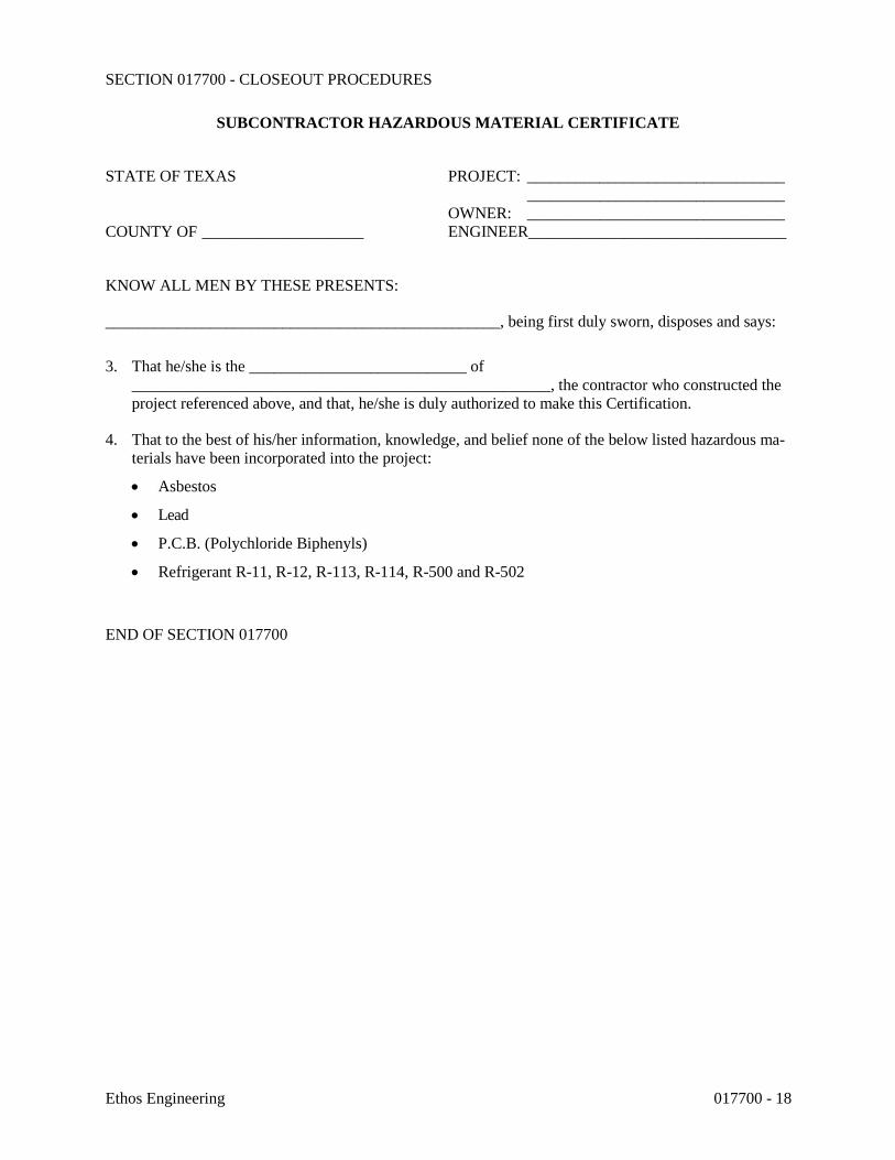
SECTION 017700 - CLOSEOUT PROCEDURES
Ethos Engineering 017700 - 18
SUBCONTRACTOR HAZARDOUS MATERIAL CERTIFICATE
STATE OF TEXAS PROJECT: ________________________________ ________________________________ OWNER: ________________________________ COUNTY OF ____________________ ENGINEER________________________________
KNOW ALL MEN BY THESE PRESENTS:
_________________________________________________, being first duly sworn, disposes and says:
3. That he/she is the ___________________________ of ____________________________________________________, the contractor who constructed the project referenced above, and that, he/she is duly authorized to make this Certification.
4. That to the best of his/her information, knowledge, and belief none of the below listed hazardous ma-terials have been incorporated into the project:
• Asbestos
• Lead
• P.C.B. (Polychloride Biphenyls)
• Refrigerant R-11, R-12, R-113, R-114, R-500 and R-502
END OF SECTION 017700

SECTION 017823 - OPERATION AND MAINTENANCE DATA
Ethos Engineering 017823 - 1
PART 1 - GENERAL
1.1 RELATED DOCUMENTS
A. Drawings and general provisions of the Contract, including General and Supplementary Conditions and other Division 01 Specification Sections, apply to this Section.
1.2 SUMMARY
A. Section includes administrative and procedural requirements for preparing operation and maintenance manuals, including the following:
1. Operation and maintenance documentation directory. 2. Emergency manuals. 3. Operation manuals for systems, subsystems, and equipment. 4. Product maintenance manuals. 5. Systems and equipment maintenance manuals.
1.3 DEFINITIONS
A. System: An organized collection of parts, equipment, or subsystems united by regular interaction.
B. Subsystem: A portion of a system with characteristics similar to a system.
1.4 CLOSEOUT SUBMITTALS
A. Manual Content: Operations and maintenance manual content is specified in individual Specification Sections to be reviewed at the time of Section submittals. Submit reviewed manual content formatted and organized as required by this Section.
1. Architect will comment on whether content of operations and maintenance submittals are acceptable.
2. Where applicable, clarify and update reviewed manual content to correspond to revisions and field conditions.
B. Format: Submit operations and maintenance manuals in the following format:
1. PDF electronic file. Assemble each manual into a composite electronically indexed file. Submit on digital media acceptable to Architect.
a. Name each indexed document file in composite electronic index with applicable item name. Include a complete electronically linked operation and maintenance directory.
b. Enable inserted reviewer comments on draft submittals.

SECTION 017823 - OPERATION AND MAINTENANCE DATA
Ethos Engineering 017823 - 2
2. Three paper copies. Include a complete operation and maintenance directory. Enclose title pages and directories in clear plastic sleeves. Architect will return two copies.
C. Initial Manual Submittal: Submit draft copy of each manual at least 30 days before commencing demonstration and training. Architect will comment on whether general scope and content of manual are acceptable.
D. Final Manual Submittal: Submit each manual in final form prior to requesting inspection for Substantial Completion and at least 15 days before commencing demonstration and training. Architect will return copy with comments.
PART 2 - PRODUCTS
2.1 OPERATION AND MAINTENANCE DOCUMENTATION DIRECTORY
A. Directory: Prepare a single, comprehensive directory of emergency, operation, and maintenance data and materials, listing items and their location to facilitate ready access to desired information. Include a section in the directory for each of the following:
1. List of documents. 2. List of systems. 3. List of equipment. 4. Table of contents.
B. List of Systems and Subsystems: List systems alphabetically. Include references to operation and maintenance manuals that contain information about each system.
C. List of Equipment: List equipment for each system, organized alphabetically by system. For pieces of equipment not part of system, list alphabetically in separate list.
D. Tables of Contents: Include a table of contents for each emergency, operation, and maintenance manual.
E. Identification: In the documentation directory and in each operation and maintenance manual, identify each system, subsystem, and piece of equipment with same designation used in the Contract Documents. If no designation exists, assign a designation according to ASHRAE Guideline 4, "Preparation of Operating and Maintenance Documentation for Building Systems."
2.2 REQUIREMENTS FOR EMERGENCY, OPERATION, AND MAINTENANCE MANUALS
A. Organization: Unless otherwise indicated, organize each manual into a separate section for each system and subsystem, and a separate section for each piece of equipment not part of a system. Each manual shall contain the following materials, in the order listed:
1. Title page. 2. Table of contents. 3. Manual contents.

SECTION 017823 - OPERATION AND MAINTENANCE DATA
Ethos Engineering 017823 - 3
B. Title Page: Include the following information:
1. Subject matter included in manual. 2. Name and address of Project. 3. Name and address of Owner. 4. Date of submittal. 5. Name and contact information for Contractor. 6. Name and contact information for Construction Manager. 7. Name and contact information for Architect. 8. Name and contact information for Commissioning Authority. 9. Names and contact information for major consultants to the Architect that designed the
systems contained in the manuals. 10. Cross-reference to related systems in other operation and maintenance manuals.
C. Table of Contents: List each product included in manual, identified by product name, indexed to the content of the volume, and cross-referenced to Specification Section number in Project Manual.
1. If operation or maintenance documentation requires more than one volume to accommodate data, include comprehensive table of contents for all volumes in each volume of the set.
D. Manual Contents: Organize into sets of manageable size. Arrange contents alphabetically by system, subsystem, and equipment. If possible, assemble instructions for subsystems, equipment, and components of one system into a single binder.
E. Manuals, Electronic Files: Submit manuals in the form of a multiple file composite electronic PDF file for each manual type required.
1. Electronic Files: Use electronic files prepared by manufacturer where available. Where scanning of paper documents is required, configure scanned file for minimum readable file size.
2. File Names and Bookmarks: Enable bookmarking of individual documents based on file names. Name document files to correspond to system, subsystem, and equipment names used in manual directory and table of contents. Group documents for each system and subsystem into individual composite bookmarked files, then create composite manual, so that resulting bookmarks reflect the system, subsystem, and equipment names in a readily navigated file tree. Configure electronic manual to display bookmark panel on opening file.
F. Manuals, Paper Copy: Submit manuals in the form of hard copy, bound and labeled volumes.
1. Binders: Heavy-duty, three-ring, vinyl-covered, loose-leaf binders, in thickness necessary to accommodate contents, sized to hold 8-1/2-by-11-inch paper; with clear plastic sleeve on spine to hold label describing contents and with pockets inside covers to hold folded oversize sheets.
a. If two or more binders are necessary to accommodate data of a system, organize data in each binder into groupings by subsystem and related components. Cross-reference other binders if necessary to provide essential information for proper operation or maintenance of equipment or system.

SECTION 017823 - OPERATION AND MAINTENANCE DATA
Ethos Engineering 017823 - 4
b. Identify each binder on front and spine, with printed title "OPERATION AND MAINTENANCE MANUAL," Project title or name, and subject matter of contents, and indicate Specification Section number on bottom of spine. Indicate volume number for multiple-volume sets.
2. Dividers: Heavy-paper dividers with plastic-covered tabs for each section of the manual. Mark each tab to indicate contents. Include typed list of products and major components of equipment included in the section on each divider, cross-referenced to Specification Section number and title of Project Manual.
3. Protective Plastic Sleeves: Transparent plastic sleeves designed to enclose diagnostic software storage media for computerized electronic equipment.
4. Supplementary Text: Prepared on 8-1/2-by-11-inch white bond paper. 5. Drawings: Attach reinforced, punched binder tabs on drawings and bind with text.
a. If oversize drawings are necessary, fold drawings to same size as text pages and use as foldouts.
b. If drawings are too large to be used as foldouts, fold and place drawings in labeled envelopes and bind envelopes in rear of manual. At appropriate locations in manual, insert typewritten pages indicating drawing titles, descriptions of contents, and drawing locations.
2.3 EMERGENCY MANUALS
A. Content: Organize manual into a separate section for each of the following:
1. Type of emergency. 2. Emergency instructions. 3. Emergency procedures.
B. Type of Emergency: Where applicable for each type of emergency indicated below, include instructions and procedures for each system, subsystem, piece of equipment, and component:
1. Fire. 2. Flood. 3. Gas leak. 4. Water leak. 5. Power failure. 6. Water outage. 7. System, subsystem, or equipment failure. 8. Chemical release or spill.
C. Emergency Instructions: Describe and explain warnings, trouble indications, error messages, and similar codes and signals. Include responsibilities of Owner's operating personnel for notification of Installer, supplier, and manufacturer to maintain warranties.
D. Emergency Procedures: Include the following, as applicable:
1. Instructions on stopping. 2. Shutdown instructions for each type of emergency. 3. Operating instructions for conditions outside normal operating limits.

SECTION 017823 - OPERATION AND MAINTENANCE DATA
Ethos Engineering 017823 - 5
4. Required sequences for electric or electronic systems. 5. Special operating instructions and procedures.
2.4 OPERATION MANUALS
A. Content: In addition to requirements in this Section, include operation data required in individual Specification Sections and the following information:
1. System, subsystem, and equipment descriptions. Use designations for systems and equipment indicated on Contract Documents.
2. Performance and design criteria if Contractor has delegated design responsibility. 3. Operating standards. 4. Operating procedures. 5. Operating logs. 6. Wiring diagrams. 7. Control diagrams. 8. Piped system diagrams. 9. Precautions against improper use. 10. License requirements including inspection and renewal dates.
B. Descriptions: Include the following:
1. Product name and model number. Use designations for products indicated on Contract Documents.
2. Manufacturer's name. 3. Equipment identification with serial number of each component. 4. Equipment function. 5. Operating characteristics. 6. Limiting conditions. 7. Performance curves. 8. Engineering data and tests. 9. Complete nomenclature and number of replacement parts.
C. Operating Procedures: Include the following, as applicable:
1. Startup procedures. 2. Equipment or system break-in procedures. 3. Routine and normal operating instructions. 4. Regulation and control procedures. 5. Instructions on stopping. 6. Normal shutdown instructions. 7. Seasonal and weekend operating instructions. 8. Required sequences for electric or electronic systems. 9. Special operating instructions and procedures.
D. Systems and Equipment Controls: Describe the sequence of operation, and diagram controls as installed.
E. Piped Systems: Diagram piping as installed, and identify color-coding where required for identification.

SECTION 017823 - OPERATION AND MAINTENANCE DATA
Ethos Engineering 017823 - 6
2.5 PRODUCT MAINTENANCE MANUALS
A. Content: Organize manual into a separate section for each product, material, and finish. Include source information, product information, maintenance procedures, repair materials and sources, and warranties and bonds, as described below.
B. Source Information: List each product included in manual, identified by product name and arranged to match manual's table of contents. For each product, list name, address, and telephone number of Installer or supplier and maintenance service agent, and cross-reference Specification Section number and title in Project Manual and drawing or schedule designation or identifier where applicable.
C. Product Information: Include the following, as applicable:
1. Product name and model number. 2. Manufacturer's name. 3. Color, pattern, and texture. 4. Material and chemical composition. 5. Reordering information for specially manufactured products.
D. Maintenance Procedures: Include manufacturer's written recommendations and the following:
1. Inspection procedures. 2. Types of cleaning agents to be used and methods of cleaning. 3. List of cleaning agents and methods of cleaning detrimental to product. 4. Schedule for routine cleaning and maintenance. 5. Repair instructions.
E. Repair Materials and Sources: Include lists of materials and local sources of materials and related services.
F. Warranties and Bonds: Include copies of warranties and bonds and lists of circumstances and conditions that would affect validity of warranties or bonds.
1. Include procedures to follow and required notifications for warranty claims.
2.6 SYSTEMS AND EQUIPMENT MAINTENANCE MANUALS
A. Content: For each system, subsystem, and piece of equipment not part of a system, include source information, manufacturers' maintenance documentation, maintenance procedures, maintenance and service schedules, spare parts list and source information, maintenance service contracts, and warranty and bond information, as described below.
B. Source Information: List each system, subsystem, and piece of equipment included in manual, identified by product name and arranged to match manual's table of contents. For each product, list name, address, and telephone number of Installer or supplier and maintenance service agent, and cross-reference Specification Section number and title in Project Manual and drawing or schedule designation or identifier where applicable.

SECTION 017823 - OPERATION AND MAINTENANCE DATA
Ethos Engineering 017823 - 7
C. Manufacturers' Maintenance Documentation: Manufacturers' maintenance documentation including the following information for each component part or piece of equipment:
1. Standard maintenance instructions and bulletins. 2. Drawings, diagrams, and instructions required for maintenance, including disassembly
and component removal, replacement, and assembly. 3. Identification and nomenclature of parts and components. 4. List of items recommended to be stocked as spare parts.
D. Maintenance Procedures: Include the following information and items that detail essential maintenance procedures:
1. Test and inspection instructions. 2. Troubleshooting guide. 3. Precautions against improper maintenance. 4. Disassembly; component removal, repair, and replacement; and reassembly instructions. 5. Aligning, adjusting, and checking instructions. 6. Demonstration and training video recording, if available.
E. Maintenance and Service Schedules: Include service and lubrication requirements, list of required lubricants for equipment, and separate schedules for preventive and routine maintenance and service with standard time allotment.
1. Scheduled Maintenance and Service: Tabulate actions for daily, weekly, monthly, quarterly, semiannual, and annual frequencies.
2. Maintenance and Service Record: Include manufacturers' forms for recording maintenance.
F. Spare Parts List and Source Information: Include lists of replacement and repair parts, with parts identified and cross-referenced to manufacturers' maintenance documentation and local sources of maintenance materials and related services.
G. Maintenance Service Contracts: Include copies of maintenance agreements with name and telephone number of service agent.
H. Warranties and Bonds: Include copies of warranties and bonds and lists of circumstances and conditions that would affect validity of warranties or bonds.
1. Include procedures to follow and required notifications for warranty claims.
PART 3 - EXECUTION
3.1 MANUAL PREPARATION
A. Operation and Maintenance Documentation Directory: Prepare a separate manual that provides an organized reference to emergency, operation, and maintenance manuals.
SECTION 017823 - OPERATION AND MAINTENANCE DATA
Ethos Engineering 017823 - 8
B. Emergency Manual: Assemble a complete set of emergency information indicating procedures for use by emergency personnel and by Owner's operating personnel for types of emergencies indicated.
C. Product Maintenance Manual: Assemble a complete set of maintenance data indicating care and maintenance of each product, material, and finish incorporated into the Work.
D. Operation and Maintenance Manuals: Assemble a complete set of operation and maintenance data indicating operation and maintenance of each system, subsystem, and piece of equipment not part of a system.
1. Engage a factory-authorized service representative to assemble and prepare information for each system, subsystem, and piece of equipment not part of a system.
2. Prepare a separate manual for each system and subsystem, in the form of an instructional manual for use by Owner's operating personnel.
E. Manufacturers' Data: Where manuals contain manufacturers' standard printed data, include only sheets pertinent to product or component installed. Mark each sheet to identify each product or component incorporated into the Work. If data include more than one item in a tabular format, identify each item using appropriate references from the Contract Documents. Identify data applicable to the Work and delete references to information not applicable.
1. Prepare supplementary text if manufacturers' standard printed data are not available and where the information is necessary for proper operation and maintenance of equipment or systems.
F. Drawings: Prepare drawings supplementing manufacturers' printed data to illustrate the relationship of component parts of equipment and systems and to illustrate control sequence and flow diagrams. Coordinate these drawings with information contained in record Drawings to ensure correct illustration of completed installation.
1. Do not use original project record documents as part of operation and maintenance manuals.
2. Comply with requirements of newly prepared record Drawings in Section 017839 "Project Record Documents."
G. Comply with Section 017700 "Closeout Procedures" for schedule for submitting operation and maintenance documentation.
END OF SECTION 017823

SECTION 017900 - DEMONSTRATION AND TRAINING
Ethos Engineering 017900 - 1
PART 1 - GENERAL
1.1 RELATED DOCUMENTS
A. Drawings and general provisions of the Contract, including General and Supplementary Conditions and other Division 01 Specification Sections, apply to this Section.
1.2 SUMMARY
A. Section includes administrative and procedural requirements for instructing Owner's personnel, including the following:
1. Demonstration of operation of systems, subsystems, and equipment. 2. Training in operation and maintenance of systems, subsystems, and equipment. 3. Demonstration and training video recordings.
B. Allowances: Furnish demonstration and training instruction time under the Demonstration and Training Allowance as specified in Section 012100 "Allowances."
1.3 INFORMATIONAL SUBMITTALS
A. Instruction Program: Submit outline of instructional program for demonstration and training, including a list of training modules and a schedule of proposed dates, times, length of instruction time, and instructors' names for each training module. Include learning objective and outline for each training module.
1. Indicate proposed training modules using manufacturer-produced demonstration and training video recordings for systems, equipment, and products in lieu of video recording of live instructional module.
B. Attendance Record: For each training module, submit list of participants and length of instruction time.
C. Evaluations: For each participant and for each training module, submit results and documentation of performance-based test.
1.4 CLOSEOUT SUBMITTALS
A. Demonstration and Training Video Recordings: Submit two copies within seven days of end of each training module.
1. Identification: On each copy, provide an applied label with the following information:
a. Name of Project. b. Name and address of videographer. c. Name of Architect.

SECTION 017900 - DEMONSTRATION AND TRAINING
Ethos Engineering 017900 - 2
d. Name of Construction Manager. e. Name of Contractor. f. Date of video recording.
2. Transcript: Prepared and bound in format matching operation and maintenance manuals. Mark appropriate identification on front and spine of each binder. Include a cover sheet with same label information as the corresponding video recording. Include name of Project and date of video recording on each page.
3. Transcript: Prepared in PDF electronic format. Include a cover sheet with same label information as the corresponding video recording and a table of contents with links to corresponding training components. Include name of Project and date of video recording on each page.
4. At completion of training, submit complete training manual(s) for Owner's use in PDF electronic file format on compact disc.
1.5 QUALITY ASSURANCE
A. Facilitator Qualifications: A firm or individual experienced in training or educating maintenance personnel in a training program similar in content and extent to that indicated for this Project, and whose work has resulted in training or education with a record of successful learning performance.
B. Instructor Qualifications: A factory-authorized service representative, complying with requirements in "Quality Requirements," experienced in operation and maintenance procedures and training.
C. Videographer Qualifications: A professional videographer who is experienced photographing demonstration and training events similar to those required.
D. Preinstruction Conference: Conduct conference at Project site to comply with requirements in Section 013100 "Project Management and Coordination." Review methods and procedures related to demonstration and training including, but not limited to, the following:
1. Inspect and discuss locations and other facilities required for instruction. 2. Review and finalize instruction schedule and verify availability of educational materials,
instructors' personnel, audiovisual equipment, and facilities needed to avoid delays. 3. Review required content of instruction. 4. For instruction that must occur outside, review weather and forecasted weather conditions
and procedures to follow if conditions are unfavorable.
1.6 COORDINATION
A. Coordinate instruction schedule with Owner's operations. Adjust schedule as required to minimize disrupting Owner's operations and to ensure availability of Owner's personnel.
B. Coordinate instructors, including providing notification of dates, times, length of instruction time, and course content.

SECTION 017900 - DEMONSTRATION AND TRAINING
Ethos Engineering 017900 - 3
C. Coordinate content of training modules with content of approved emergency, operation, and maintenance manuals. Do not submit instruction program until operation and maintenance data has been reviewed and approved by Architect.
PART 2 - PRODUCTS
2.1 INSTRUCTION PROGRAM
A. Program Structure: Develop an instruction program that includes individual training modules for each system and for equipment not part of a system, as required by individual Specification Sections.
B. Training Modules: Develop a learning objective and teaching outline for each module. Include a description of specific skills and knowledge that participant is expected to master. For each module, include instruction for the following as applicable to the system, equipment, or component:
1. Basis of System Design, Operational Requirements, and Criteria: Include the following:
a. System, subsystem, and equipment descriptions. b. Performance and design criteria if Contractor is delegated design responsibility. c. Operating standards. d. Regulatory requirements. e. Equipment function. f. Operating characteristics. g. Limiting conditions. h. Performance curves.
2. Documentation: Review the following items in detail:
a. Emergency manuals. b. Operations manuals. c. Maintenance manuals. d. Project record documents. e. Identification systems. f. Warranties and bonds. g. Maintenance service agreements and similar continuing commitments.
3. Emergencies: Include the following, as applicable:
a. Instructions on meaning of warnings, trouble indications, and error messages. b. Instructions on stopping. c. Shutdown instructions for each type of emergency. d. Operating instructions for conditions outside of normal operating limits. e. Sequences for electric or electronic systems. f. Special operating instructions and procedures.
4. Operations: Include the following, as applicable:

SECTION 017900 - DEMONSTRATION AND TRAINING
Ethos Engineering 017900 - 4
a. Startup procedures. b. Equipment or system break-in procedures. c. Routine and normal operating instructions. d. Regulation and control procedures. e. Control sequences. f. Safety procedures. g. Instructions on stopping. h. Normal shutdown instructions. i. Operating procedures for emergencies. j. Operating procedures for system, subsystem, or equipment failure. k. Seasonal and weekend operating instructions. l. Required sequences for electric or electronic systems. m. Special operating instructions and procedures.
5. Adjustments: Include the following:
a. Alignments. b. Checking adjustments. c. Noise and vibration adjustments. d. Economy and efficiency adjustments.
6. Troubleshooting: Include the following:
a. Diagnostic instructions. b. Test and inspection procedures.
7. Maintenance: Include the following:
a. Inspection procedures. b. Types of cleaning agents to be used and methods of cleaning. c. List of cleaning agents and methods of cleaning detrimental to product. d. Procedures for routine cleaning e. Procedures for preventive maintenance. f. Procedures for routine maintenance. g. Instruction on use of special tools.
8. Repairs: Include the following:
a. Diagnosis instructions. b. Repair instructions. c. Disassembly; component removal, repair, and replacement; and reassembly
instructions. d. Instructions for identifying parts and components. e. Review of spare parts needed for operation and maintenance.

SECTION 017900 - DEMONSTRATION AND TRAINING
Ethos Engineering 017900 - 5
PART 3 - EXECUTION
3.1 PREPARATION
A. Assemble educational materials necessary for instruction, including documentation and training module. Assemble training modules into a training manual organized in coordination with requirements in Section 017823 "Operation and Maintenance Data."
B. Set up instructional equipment at instruction location.
3.2 INSTRUCTION
A. Facilitator: Engage a qualified facilitator to prepare instruction program and training modules, to coordinate instructors, and to coordinate between Contractor and Owner for number of participants, instruction times, and location.
B. Engage qualified instructors to instruct Owner's personnel to adjust, operate, and maintain systems, subsystems, and equipment not part of a system.
1. Architect will furnish an instructor to describe basis of system design, operational requirements, criteria, and regulatory requirements.
2. Owner will furnish an instructor to describe Owner's operational philosophy. 3. Owner will furnish Contractor with names and positions of participants.
C. Scheduling: Provide instruction at mutually agreed on times. For equipment that requires seasonal operation, provide similar instruction at start of each season.
1. Schedule training with Owner with at least seven days' advance notice.
D. Training Location and Reference Material: Conduct training on-site in the completed and fully operational facility using the actual equipment in-place. Conduct training using final operation and maintenance data submittals.
E. Evaluation: At conclusion of each training module, assess and document each participant's mastery of module by use of a written performance-based test.
F. Cleanup: Collect used and leftover educational materials and give to Owner. Remove instructional equipment. Restore systems and equipment to condition existing before initial training use.
3.3 DEMONSTRATION AND TRAINING VIDEO RECORDINGS
A. General: Engage a qualified commercial videographer to record demonstration and training video recordings. Record each training module separately. Include classroom instructions and demonstrations, board diagrams, and other visual aids, but not student practice.
1. At beginning of each training module, record each chart containing learning objective and lesson outline.

SECTION 017900 - DEMONSTRATION AND TRAINING
Ethos Engineering 017900 - 6
B. Video: Provide minimum 640 x 480 video resolution converted to format file type acceptable to Owner, on electronic media.
1. Electronic Media: Read-only format compact disc acceptable to Owner, with commercial-grade graphic label.
2. File Hierarchy: Organize folder structure and file locations according to project manual table of contents. Provide complete screen-based menu.
3. File Names: Utilize file names based upon name of equipment generally described in video segment, as identified in Project specifications.
4. Contractor and Installer Contact File: Using appropriate software, create a file for inclusion on the Equipment Demonstration and Training DVD that describes the following for each Contractor involved on the Project, arranged according to Project table of contents:
a. Name of Contractor/Installer. b. Business address. c. Business phone number. d. Point of contact. e. E-mail address.
C. Recording: Mount camera on tripod before starting recording, unless otherwise necessary to adequately cover area of demonstration and training. Display continuous running time.
1. Film training session(s) in segments not to exceed 15 minutes.
a. Produce segments to present a single significant piece of equipment per segment. b. Organize segments with multiple pieces of equipment to follow order of Project
Manual table of contents. c. Where a training session on a particular piece of equipment exceeds 15 minutes,
stop filming and pause training session. Begin training session again upon commencement of new filming segment.
D. Light Levels: Verify light levels are adequate to properly light equipment. Verify equipment markings are clearly visible prior to recording.
1. Furnish additional portable lighting as required.
E. Narration: Describe scenes on video recording by audio narration by microphone while video recording is recorded. Include description of items being viewed.
F. Transcript: Provide a transcript of the narration. Display images and running time captured from videotape opposite the corresponding narration segment.
G. Preproduced Video Recordings: Provide video recordings used as a component of training modules in same format as recordings of live training.
END OF SECTION 017900

SECTION 260010 - SUMMARY OF ELECTRICAL WORK
Ethos Engineering 260010 - 1
PART 1 - GENERAL 1.1 RELATED DOCUMENTS
A. Drawings and general provisions of the Contract, including General and Supplementary
Conditions, Division 1 Specification Sections and other Division 26 Specification Sections, apply to this Section.
1.2 WORK COVERED BY CONTRACT DOCUMENTS
A. The following Summary of Work is intended as an aid to achieve an understanding of the
various elements of work included in the project, as is not intended to be all-inclusive. Detailed descriptions of work and requirements are given in drawings and specifications.
B. Scope of Work:
1. General: The “H.W.W.S. MF Runnion Water Treatment Plant Raw Water & High Service VFD’s and Upgrades R.F.P. #16505” consists of providing three pumps with variable frequency controllers.
2. Electrical: Provide all materials and labor associated with complete operational electrical distribution system. Major items of work include, but are not limited to:
(a) Electrical service: Existing to remain.
(b) Motor Control Centers: Existing to remain with modifications. Existing MOCP shall be connected to new VFD with Bypass.
(c) Lighting systems: Provide LED type fixtures and wall switches as noted on plans.
(d) Power systems: Disconnect existing Solid state motor starters and provide VFD’s for existing high pressure service pumps and raw water pump. Existing MOCP protection shall connect to new VFD. Interconnect new VFD with existing solid state motor starters on the bypass mode, provide wiring as required.
(e) Control wiring: Remove existing wiring and provide new wiring to be interface with new VFD’s. Coordinate connections with VFD provider prior to bid opening to ensure proper connections.
1.3 ALLOWANCES
A. Electrical: See Division 1 for electrical allowances.
1.4 COORDINATION
A. All electrical work shall be done under sub-contract to a General Contractor, who ultimately responsible for the entire project. Electrical Contractor shall coordinate all work through General Contractor, even in areas where only electrical work is to take place.

SECTION 260010 - SUMMARY OF ELECTRICAL WORK
Ethos Engineering 260010 - 2
B. All questions, requests for information, submittals, and correspondence from the Electrical Contractor shall be submitted via the General Contractor, who will forward to the Architect, who will then forward to the Engineer.
C. Electrical Contractor shall not make any changes to design without written authorization from the Engineer. If changes are requested by the Owner, Architect, General Contractor, Suppliers, Manufacturers, or any others, Contractor should issue a written RFI for response by the Engineer.
D. Electrical Contractor shall issue seven (7) days written notice prior to any activities that require the presence of the Engineer at the job-site. This applies to all inspections required by specifications, and particularly to those where work will be covered (underground raceways, electrical raceways above ceiling).
E. Cooperate fully with other contractors so that work under those contracts may be carried out smoothly, without interfering with or delaying work under this Contract.
F. Fully coordinate with the VFD supplier for the equipment installation.
G. Issue written notification of the following tasks and allow five (5) days for Engineer to respond and schedule an inspection as required:
1. Upon completion of underground raceways installation and prior to covering up. 2. Upon completion of installing all raceways, labeling all j-boxes and prior to suspended
ceiling installation. 3. Upon completion of pulling all wiring, making all terminations, labeling and color-coding
wires at the panelboards/switchboards and prior to installing their covers. 4. When ready to request manufacturer’s start-up of each piece of equipment. 5. When ready for Substantial Completion Inspection. 6. When ready for Final Inspection.
Failure to issue written notification may result in work having to be redone to allow for proper
inspection. It is this contractor’s responsibility to make sure Engineer receives notification. 1.5 UTILITIES
1. Coordinate with power, water, telephone, cable and gas utilities to locate all utilities prior to digging in any area.
2. Obtain any approvals required from utilities to relocate utilities. 3. Cost of relocating or bypassing utilities indicated on drawings shall be included in Base
Bid.
1.6 CONTRACTOR USE OF PREMISES A. Use of the Site: Limit use of the premises to work in areas indicated. Confine operations to
areas within contract limits indicated. Do not disturb portions of the site beyond the areas in which the Work is indicated. 1. Owner Occupancy: Allow for Owner occupancy and use by the public. 2. Driveways and Entrances: Keep driveways and entrances serving the premises, clear
and available to the Owner, the Owner's employees, and emergency vehicles at all time. Do not use these areas for parking or storage of materials. Schedule deliveries to minimize space and time requirements for storage of materials and equipment on-site.

SECTION 260010 - SUMMARY OF ELECTRICAL WORK
Ethos Engineering 260010 - 3
B. Site Safety: Take every precaution to ensure the site does not present a threat to the safety of occupants and/or workers. Minimal safety requirements include, but are not limited to the following: 1. Temporary fencing around construction areas. 2. Yellow caution tape and construction barricades along open trenches during the day.
Trenches shall be covered at night and warning lights provided on construction barricades.
3. Temporary fencing around equipment while site work is in progress.
C. Work shall take place with minimal disruption to Owner's operations in areas surrounding the job site.
1.7 SUBMITTALS -Special Requirements
A. Manufacturer's standard dimensioned drawings, performance and product data shall be edited to delete reference to equipment, features, or information, which is not applicable to the equipment being supplied for this project. Including Bill or List of Materials.
B. Electrical Submittals shall be submitted electronically. Please organize the files in packages
as follows (PDF format – one file per section). Files would need to be properly identified (cover letter, stamped, etc.) from the general contractor.
1. Miscellaneous Electrical
a. 260519 Low-Voltage Electrical Power Conductors and Cables b. 260526 Grounding and Bonding for Electrical Systems c. 260529 Hangers and Supports for Electrical Systems d. 260533 Raceways and Boxes for Electrical Systems e. 260553 Identification for Electrical Systems f. 260544 Sleeves and Sleeve Seals for Electrical Raceways and Cabling
2. Electrical Gear a. 262923 Variable Frequency Motor Controllers
3. Light Fixtures a. 265116 Interior Lighting b. 265219 Emergency and Exit Lighting
E. Individual submittals shall not be reviewed until a complete package is received. F. Allow two weeks for initial submittal review by Engineer, from the day it is received at the
Engineer's office. G. Allow one week for review of resubmittals by Engineer. H. All submittal review comments shall be forwarded by Engineer to Architect, who will then
distribute as per Division 1.
1.8 SCHEDULE OF VALUES -Special Requirements

SECTION 260010 - SUMMARY OF ELECTRICAL WORK
Ethos Engineering 260010 - 4
A. Electrical Contractor shall submit a Schedule of Values reflecting the total value of Electrical Work in the Contract, and broken down into the following items as a minimum, with a line item for Materials/Equipment and another for Labor.
ELECTRICAL
1. Variable Frequency Motor Controllers 2. Raceways including wiring. 3. Light fixtures 4. Allowances. 5. Miscellaneous. 6. Administrative and project management.
1.9 CODE COMPLIANCE:
The design for this project is based on:
1. Occupational Safety and Health Act (OSHA) 2. National Electric Code (NEC) 3. National Fire Code 4. International Building Code 5. UL 916 6. Local ordinances
END OF SECTION 260010
SECTION 260519 - LOW-VOLTAGE ELECTRICAL POWER CONDUCTORS AND CABLES
Ethos Engineering 260519 - 1
PART 1 - GENERAL
1.1 RELATED DOCUMENTS
A. Drawings and general provisions of the Contract, including General and Supplementary Conditions and Division 01 Specification Sections, apply to this Section.
1.2 SUMMARY
A. Section Includes:
1. Building wires and cables rated 600 V and less. 2. Connectors, splices, and terminations rated 600 V and less.
1.3 DEFINITIONS
A. VFC: Variable frequency controller.
1.4 ACTION SUBMITTALS
A. Product Data: For each type of product.
1.5 INFORMATIONAL SUBMITTALS
A. Qualification Data: For testing agency.
B. Field quality-control reports.
1.6 QUALITY ASSURANCE
A. Testing Agency Qualifications: Member Company of NETA or an NRTL.
PART 2 - PRODUCTS
2.1 CONDUCTORS AND CABLES
A. Manufacturer:
1. Senator Wire & Cable Company. 2. Southwire Company. 3. Encore Wire

SECTION 260519 - LOW-VOLTAGE ELECTRICAL POWER CONDUCTORS AND CABLES
Ethos Engineering 260519 - 2
B. Copper Conductors: Comply with NEMA WC 70/ICEA S-95-658.
C. Conductor Insulation: Comply with NEMA WC 70/ICEA S-95-658 for Type THHN/THWN-2, Type XHHW-2 and Type SO.
D. Multiconductor Cable: Comply with NEMA WC 70/ICEA S-95-658 for metal-clad cable, Type MC and Type SO with ground wire.
E. VFC Cable:
1. Comply with UL 1277, UL 1685, and NFPA 70 for Type TC-ER cable. 2. Type TC-ER with oversized cross-linked polyethylene insulation, spiral-wrapped foil
plus 85 percent coverage braided shields and insulated full-size ground wire or dual spirally wrapped copper tape shields and three bare symmetrically applied ground wires, and sunlight- and oil-resistant outer PVC jacket.
3. Comply with UL requirements for cables in [Classes I and II, Division 2 hazardous location] applications.
2.2 CONNECTORS AND SPLICES
A. Manufacturers:
1. AFC Cable Systems, Inc. 2. AMP Incorporated/Tyco International. 3. Hubbell/Anderson. 4. O-Z/Gedney; EGS Electrical Group LLC. 5. 3M Company; Electrical Products Division.
B. Description: Factory-fabricated connectors and splices of size, ampacity rating, material, type, and class for application and service indicated.
2.3 SYSTEM DESCRIPTION
A. Electrical Components, Devices, and Accessories: Listed and labeled as defined in NFPA 70, by a qualified testing agency, and marked for intended location and application.
B. Comply with NFPA 70.
PART 3 - EXECUTION
3.1 CONDUCTOR MATERIAL APPLICATIONS
A. Feeders: Copper. Solid for No. 10 AWG and smaller; stranded for No. 8 AWG and larger.
B. Branch Circuits: Copper. Solid for No. 10 AWG and smaller; stranded for No. 8 AWG and larger, except VFC cable, which shall be extra flexible stranded.

SECTION 260519 - LOW-VOLTAGE ELECTRICAL POWER CONDUCTORS AND CABLES
Ethos Engineering 260519 - 3
3.2 CONDUCTOR INSULATION AND MULTICONDUCTOR CABLE APPLICATIONS AND WIRING METHODS
A. Exposed Branch Circuits, Including in Crawlspaces: Type THHN/THWN-2, single conductors in raceway.
B. Branch Circuits Concealed in Ceilings, Walls, and Partitions: Type THHN/THWN-2, single conductors in raceway.
C. Branch Circuits Concealed in Concrete, below Slabs-on-Grade, and underground: Type THHN/THWN-2, single conductors in raceway.
D. VFC Output Circuits: Type XHHW-2 in metal conduit, Type TC-ER cable with braided shield or with dual tape shield as indicated by VFC manufacturer.
3.3 INSTALLATION OF CONDUCTORS AND CABLES
A. Conceal cables in finished walls, ceilings, and floors unless otherwise indicated.
B. Complete raceway installation between conductor and cable termination points according to Section 260533 "Raceways and Boxes for Electrical Systems" prior to pulling conductors and cables.
C. Use manufacturer-approved pulling compound or lubricant where necessary; compound used must not deteriorate conductor or insulation. Do not exceed manufacturer's recommended maximum pulling tensions and sidewall pressure values.
D. Use pulling means, including fish tape, cable, rope, and basket-weave wire/cable grips, which will not damage cables or raceway.
E. Install exposed cables parallel and perpendicular to surfaces of exposed structural members, and follow surface contours where possible.
F. Support cables according to Section 260529 "Hangers and Supports for Electrical Systems."
3.4 CONNECTIONS
A. Tighten electrical connectors and terminals according to manufacturer's published torque-tightening values. If manufacturer's torque values are not indicated, use those specified in UL 486A-486B.
B. Make splices, terminations, and taps that are compatible with conductor material and that possess equivalent or better mechanical strength and insulation ratings than unspliced conductors.
1. Use oxide inhibitor in each splice, termination, and tap for aluminum conductors.
C. Wiring at Outlets: Install conductor at each outlet, with at least 6 inches of slack.

SECTION 260519 - LOW-VOLTAGE ELECTRICAL POWER CONDUCTORS AND CABLES
Ethos Engineering 260519 - 4
3.5 IDENTIFICATION
A. Identify and color-code conductors and cables according to Section 260553 "Identification for Electrical Systems."
B. Identify each spare conductor at each end with identity number and location of other end of conductor, and identify as spare conductor.
3.6 SLEEVE AND SLEEVE-SEAL INSTALLATION FOR ELECTRICAL PENETRATIONS
A. Install sleeves and sleeve seals at penetrations of exterior floor and wall assemblies. Comply with requirements in Section 260544 "Sleeves and Sleeve Seals for Electrical Raceways and Cabling."
3.7 FIRESTOPPING
A. Apply firestopping to electrical penetrations of fire-rated floor and wall assemblies to restore original fire-resistance rating of assembly according to Section 078413 "Penetration Firestopping."
3.8 FIELD QUALITY CONTROL
A. Perform the following tests and inspections:
1. After installing conductors and cables and before electrical circuitry has been energized, test service entrance and feeder conductors and conductors feeding the following critical equipment and services for compliance with requirements.
a. MDF and IDF equipment feeder/branch circuit.
2. Perform each visual and mechanical inspection and electrical test stated in NETA Acceptance Testing Specification. Certify compliance with test parameters.
3. Infrared Scanning: After Substantial Completion, but not more than 60 days after Final Acceptance, perform an infrared scan of each splice in conductors No. 3 AWG and larger. Remove box and equipment covers so splices are accessible to portable scanner. Correct deficiencies determined during the scan.
a. Follow-up Infrared Scanning: Perform an additional follow-up infrared scan of each splice 11 months after date of Substantial Completion.
b. Instrument: Use an infrared scanning device designed to measure temperature or to detect significant deviations from normal values. Provide calibration record for device.
c. Record of Infrared Scanning: Prepare a certified report that identifies splices checked and that describes scanning results. Include notation of deficiencies detected, remedial action taken, and observations after remedial action.
B. Test and Inspection Reports: Prepare a written report to record the following:

SECTION 260519 - LOW-VOLTAGE ELECTRICAL POWER CONDUCTORS AND CABLES
Ethos Engineering 260519 - 5
1. Procedures used. 2. Results that comply with requirements. 3. Results that do not comply with requirements and corrective action taken to achieve
compliance with requirements.
C. Cables will be considered defective if they do not pass tests and inspections.
END OF SECTION 260519

SECTION 260526 - GROUNDING AND BONDING FOR ELECTRICAL SYSTEMS
Ethos Engineering 260526 - 1
PART 1 - GENERAL
1.1 RELATED DOCUMENTS
A. Drawings and general provisions of the Contract, including General and Supplementary Conditions and Division 01 Specification Sections, apply to this Section.
1.2 SUMMARY
A. Section includes grounding and bonding systems and equipment.
1.3 ACTION SUBMITTALS
A. Product Data: For each type of product indicated.
1.4 INFORMATIONAL SUBMITTALS
A. As-Built Data: Plans showing dimensioned as-built locations of grounding features specified in "Field Quality Control" Article.
B. Field quality-control reports.
1.5 CLOSEOUT SUBMITTALS
A. Operation and Maintenance Data: For grounding to include in emergency, operation, and maintenance manuals.
1. In addition to items specified in Section "Operation and Maintenance Data," include the following:
a. Instructions for periodic testing and inspection of grounding features at ground rings and grounding connections for separately derived systems based on and NFPA 70B.
1.6 QUALITY ASSURANCE
A. Electrical Components, Devices, and Accessories: Listed and labeled as defined in NFPA 70, by a qualified testing agency, and marked for intended location and application.
B. Comply with UL 467 for grounding and bonding materials and equipment.

SECTION 260526 - GROUNDING AND BONDING FOR ELECTRICAL SYSTEMS
Ethos Engineering 260526 - 2
PART 2 - PRODUCTS
2.1 CONDUCTORS
A. Insulated Conductors: tinned-copper wire or cable insulated for 600 V unless otherwise required by applicable Code or authorities having jurisdiction.
B. Bare Copper Conductors:
1. Solid Conductors: ASTM B 3. 2. Stranded Conductors: ASTM B 8. 3. Tinned Conductors: ASTM B 33. 4. Bonding Cable: 28 kcmil, 14 strands of No. 17 AWG conductor, 1/4 inch in diameter. 5. Bonding Conductor: No. 4 or No. 6 AWG, stranded conductor. 6. Bonding Jumper: Copper tape, braided conductors terminated with copper ferrules; 1-5/8
inches wide and 1/16 inch thick. 7. Tinned Bonding Jumper: Tinned-copper tape, braided conductors terminated with copper
ferrules; 1-5/8 inches wide and 1/16 inch thick.
2.2 CONNECTORS
A. Listed and labeled by an NRTL acceptable to authorities having jurisdiction for applications in which used and for specific types, sizes, and combinations of conductors and other items connected.
B. Bolted Connectors for Conductors and Pipes: Copper or copper alloy.
C. Bus-Bar Connectors: Mechanical type, cast silicon bronze, solderless exothermic-type wire terminals, and long-barrel, two-bolt connection to ground bus bar.
PART 3 - EXECUTION
3.1 APPLICATIONS
A. Conductors: Install solid conductor for No. 10 AWG and smaller, and stranded conductors for No. 8 AWG and larger unless otherwise indicated.
B. Underground Grounding Conductors: Install bare tinned copper conductor, No. 2/0 AWG minimum.
C. Conductor Terminations and Connections:
1. Pipe and Equipment Grounding Conductor Terminations: Bolted connectors. 2. Connections to Structural Steel: Welded connectors.

SECTION 260526 - GROUNDING AND BONDING FOR ELECTRICAL SYSTEMS
Ethos Engineering 260526 - 3
3.2 EQUIPMENT GROUNDING
A. Install insulated equipment grounding conductors with all feeders and branch circuits.
B. Install insulated equipment grounding conductors with the following items, in addition to those required by NFPA 70:
1. Feeders and branch circuits. 2. Lighting circuits. 3. Three-phase motor and appliance branch circuits. 4. Flexible raceway runs.
C. Isolated Equipment Enclosure Circuits: For designated equipment supplied by a branch circuit or feeder, isolate equipment enclosure from supply circuit raceway with a nonmetallic raceway fitting listed for the purpose. Install fitting where raceway enters enclosure, and install a separate insulated equipment grounding conductor. Isolate conductor from raceway and from panelboard grounding terminals. Terminate at equipment grounding conductor terminal of the applicable derived system or service unless otherwise indicated.
3.3 INSTALLATION
A. Grounding Conductors: Route along shortest and straightest paths possible unless otherwise indicated or required by Code. Avoid obstructing access or placing conductors where they may be subjected to strain, impact, or damage.
B. Bonding Straps and Jumpers: Install in locations accessible for inspection and maintenance except where routed through short lengths of conduit.
1. Bonding to Structure: Bond straps directly to basic structure, taking care not to penetrate any adjacent parts.
2. Bonding to Equipment Mounted on Vibration Isolation Hangers and Supports: Install bonding so vibration is not transmitted to rigidly mounted equipment.
3.4 FIELD QUALITY CONTROL
A. Tests and Inspections:
1. After installing grounding system but before permanent electrical circuits have been energized, test for compliance with requirements.
2. Inspect physical and mechanical condition. Verify tightness of accessible, bolted, electrical connections with a calibrated torque wrench according to manufacturer's written instructions.
3. Test completed grounding system at each location where a maximum ground-resistance level is specified, at service disconnect enclosure grounding terminal, at individual ground rods. Make tests at ground rods before any conductors are connected.
a. Measure ground resistance no fewer than two full days after last trace of precipitation and without soil being moistened by any means other than natural

SECTION 260526 - GROUNDING AND BONDING FOR ELECTRICAL SYSTEMS
Ethos Engineering 260526 - 4
drainage or seepage and without chemical treatment or other artificial means of reducing natural ground resistance.
b. Perform tests by fall-of-potential method according to IEEE 81.
4. Prepare dimensioned Drawings locating each, ground rod and ground-rod assembly, and other grounding electrodes. Identify each by letter in alphabetical order, and key to the record of tests and observations. Include the number of rods driven and their depth at each location, and include observations of weather and other phenomena that may affect test results. Describe measures taken to improve test results.
B. Grounding system will be considered defective if it does not pass tests and inspections.
C. Prepare test and inspection reports.
D. Report measured ground resistances that exceed the following values:
1. Power and Lighting Equipment or System with Capacity of 500 kVA and less: 10 ohms. 2. Power and Lighting Equipment or System with Capacity of 500 to 1000 kVA: 5 ohms. 3. Power and Lighting Equipment or System with Capacity More Than 1000 kVA: 3 ohms. 4. Power Distribution Units or Panelboards Serving Electronic Equipment: 3 ohm(s). 5. Manhole Grounds: 10 ohms.
E. Excessive Ground Resistance: If resistance to ground exceeds specified values, notify Architect promptly and include recommendations to reduce ground resistance.
END OF SECTION 260526

SECTION 260529 - HANGERS AND SUPPORTS FOR ELECTRICAL SYSTEMS
Ethos Engineering 260529 - 1
PART 1 - GENERAL
1.1 RELATED DOCUMENTS
A. Drawings and general provisions of the Contract, including General and Supplementary Conditions and Division 01 Specification Sections, apply to this Section.
1.2 SUMMARY
A. Section Includes:
1. Hangers and supports for electrical equipment and systems. 2. Construction requirements for concrete bases.
1.3 ACTION SUBMITTALS
A. Product Data: For each type of product.
1. Include construction details, material descriptions, dimensions of individual components and profiles, and finishes for the following:
a. Hangers. b. Steel slotted support systems. c. Trapeze hangers. d. Clamps. e. Turnbuckles. f. Sockets. g. Eye nuts. h. Saddles. i. Brackets.
2. Include rated capacities and furnished specialties and accessories.
B. Shop Drawings: For fabrication and installation details for electrical hangers and support systems.
1. Trapeze hangers. Include product data for components. 2. Steel slotted-channel systems. 3. Equipment supports.
1.4 INFORMATIONAL SUBMITTALS
A. Coordination Drawings: Reflected ceiling plan(s) and other details, drawn to scale, on which the following items are shown and coordinated with each other, using input from installers of the items involved: 1. Structural members to which hangers and supports will be attached.

SECTION 260529 - HANGERS AND SUPPORTS FOR ELECTRICAL SYSTEMS
Ethos Engineering 260529 - 2
B. Welding certificates.
1.5 QUALITY ASSURANCE
A. Welding Qualifications: Qualify procedures and personnel according to the following:
1. AWS D1.1/D1.1M. 2. AWS D1.2/D1.2M.
PART 2 - PRODUCTS
2.1 PERFORMANCE REQUIREMENTS
A. Surface-Burning Characteristics: Comply with ASTM E 84; testing by a qualified testing agency. Identify products with appropriate markings of applicable testing agency.
1. Flame Rating: Class 1. 2. Self-extinguishing according to ASTM D 635.
2.2 SUPPORT, ANCHORAGE, AND ATTACHMENT COMPONENTS
A. Steel Slotted Support Systems: Comply with MFMA-4 factory-fabricated components for field assembly. 1. Manufacturers: Subject to compliance with requirements, provide products by one of the
following:
a. Allied Tube & Conduit. b. Cooper B-Line, Inc.; a division of Cooper Industries. c. ERICO International Corporation. d. GS Metals Corp. e. Thomas & Betts Corporation. f. Unistrut; Tyco International, Ltd. g. Wesanco, Inc.
2. Material: Plain steel. 3. Channel Width: 1-1/4 inches. 4. Metallic Coatings: Hot-dip galvanized after fabrication and applied according to MFMA-
4. 5. Painted Coatings: Manufacturer's standard painted coating applied according to MFMA-
4. 6. Protect finishes on exposed surfaces from damage by applying a strippable, temporary
protective covering before shipping. 7. Channel Dimensions: Selected for applicable load criteria.
B. Conduit and Cable Support Devices: Steel hangers, clamps, and associated fittings, designed for types and sizes of raceway or cable to be supported.

SECTION 260529 - HANGERS AND SUPPORTS FOR ELECTRICAL SYSTEMS
Ethos Engineering 260529 - 3
C. Support for Conductors in Vertical Conduit: Factory-fabricated assembly consisting of threaded body and insulating wedging plug or plugs for nonarmored electrical conductors or cables in riser conduits. Plugs shall have number, size, and shape of conductor gripping pieces as required to suit individual conductors or cables supported. Body shall be made of malleable iron.
D. Structural Steel for Fabricated Supports and Restraints: ASTM A 36/A 36M steel plates, shapes, and bars; black and galvanized.
E. Mounting, Anchoring, and Attachment Components: Items for fastening electrical items or their supports to building surfaces include the following:
1. Powder-Actuated Fasteners: Threaded-steel stud, for use in hardened portland cement concrete, steel, or wood, with tension, shear, and pullout capacities appropriate for supported loads and building materials where used. a. Manufacturers: Subject to compliance with requirements, provide products by one
of the following: 1) Hilti Inc. 2) ITW Ramset/Red Head; a division of Illinois Tool Works, Inc. 3) MKT Fastening, LLC. 4) Simpson Strong-Tie Co., Inc.; Masterset Fastening Systems Unit.
2. Mechanical-Expansion Anchors: Insert-wedge-type, zinc-coated steel, for use in hardened portland cement concrete, with tension, shear, and pullout capacities appropriate for supported loads and building materials where used. a. Manufacturers: Subject to compliance with requirements, provide products by one
of the following: 1) Cooper B-Line, Inc.; a division of Cooper Industries. 2) Empire Tool and Manufacturing Co., Inc. 3) Hilti Inc. 4) ITW Ramset/Red Head; a division of Illinois Tool Works, Inc. 5) MKT Fastening, LLC
3. Concrete Inserts: Steel or malleable-iron, slotted support system units are similar to MSS Type 18 units and comply with MFMA-4 or MSS SP-58. a. Clamps for Attachment to Steel Structural Elements: MSS SP-58 units are suitable
for attached structural element. b. Through Bolts: Structural type, hex head, and high strength. Comply with
ASTM A 325. c. Toggle Bolts: All-steel springhead type. d. Hanger Rods: Threaded steel. e. Concrete Inserts: Steel or malleable-iron, slotted support system units similar to
MSS Type 18; complying with MFMA-4 or MSS SP-58. f. Clamps for Attachment to Steel Structural Elements: MSS SP-58, type suitable for
attached structural element. g. Through Bolts: Structural type, hex head, and high strength. Comply with
ASTM A 325. h. Toggle Bolts: All-steel springhead type. i. Hanger Rods: Threaded steel

SECTION 260529 - HANGERS AND SUPPORTS FOR ELECTRICAL SYSTEMS
Ethos Engineering 260529 - 4
2.3 FABRICATED METAL EQUIPMENT SUPPORT ASSEMBLIES
A. Description: Welded or bolted structural-steel shapes, shop or field fabricated to fit dimensions of supported equipment.
B. Materials: Comply with requirements in Section 055000 "Metal Fabrications" for steel shapes and plates.
PART 3 - EXECUTION
3.1 APPLICATION
A. Comply with NECA 1 and NECA 101 for application of hangers and supports for electrical equipment and systems unless requirements in this Section are stricter.
B. Comply with requirements for raceways and boxes specified in Section 260533 "Raceways and Boxes for Electrical Systems."
C. Maximum Support Spacing and Minimum Hanger Rod Size for Raceway: Space supports for EMTs and RMCs as scheduled in NECA 1, where its Table 1 lists maximum spacings that are less than those stated in] NFPA 70. Minimum rod size shall be 1/4 inch in diameter.
D. Multiple Raceways or Cables: Install trapeze-type supports fabricated with steel slotted support system, sized so capacity can be increased by at least 25 percent in future without exceeding specified design load limits.
1. Secure raceways and cables to these supports with two-bolt conduit clamps.
E. Spring-steel clamps designed for supporting single conduits without bolts may be used for 1-1/2-inch and smaller raceways serving branch circuits and communication systems above suspended ceilings and for fastening raceways to trapeze supports.
3.2 SUPPORT INSTALLATION
A. Comply with NECA 1 and NECA 101 for installation requirements except as specified in this article.
B. Raceway Support Methods: In addition to methods described in NECA 1, EMTs, and RMCs may be supported by openings through structure members, according to NFPA 70.
C. Strength of Support Assemblies: Where not indicated, select sizes of components so strength will be adequate to carry present and future static loads within specified loading limits. Minimum static design load used for strength determination shall be weight of supported components plus 200 lb.
D. Mounting and Anchorage of Surface-Mounted Equipment and Components: Anchor and fasten electrical items and their supports to building structural elements by the following methods unless otherwise indicated by code:

SECTION 260529 - HANGERS AND SUPPORTS FOR ELECTRICAL SYSTEMS
Ethos Engineering 260529 - 5
1. To Wood: Fasten with lag screws or through bolts. 2. To New Concrete: Bolt to concrete inserts. 3. To Masonry: Approved toggle-type bolts on hollow masonry units and expansion anchor
fasteners on solid masonry units. 4. To Existing Concrete: Expansion anchor fasteners. 5. Instead of expansion anchors, powder-actuated driven threaded studs provided with lock
washers and nuts may be used in existing standard-weight concrete 4 inches thick or greater. Do not use for anchorage to lightweight-aggregate concrete or for slabs less than 4 inches thick.
6. To Steel: Spring-tension clamps. 7. To Light Steel: Sheet metal screws. 8. Items Mounted on Hollow Walls and Nonstructural Building Surfaces: Mount cabinets,
panelboards, disconnect switches, control enclosures, pull and junction boxes, transformers, and other devices on slotted-channel racks attached to substrate.
E. Drill holes for expansion anchors in concrete at locations and to depths that avoid the need for reinforcing bars.
3.3 INSTALLATION OF FABRICATED METAL SUPPORTS
A. Comply with installation requirements in Architectural Section "Metal Fabrications" for site-fabricated metal supports.
B. Cut, fit, and place miscellaneous metal supports accurately in location, alignment, and elevation to support and anchor electrical materials and equipment.
C. Field Welding: Comply with AWS D1.1/D1.1M.
3.4 CONCRETE BASES
A. Construct concrete bases of dimensions indicated but not less than 4 inches larger in both directions than supported unit, and so anchors will be a minimum of 10 bolt diameters from edge of the base.
B. Use 3000-psi, 28-day compressive-strength concrete. Concrete materials, reinforcement, and placement requirements are specified in Sections "Cast-in-Place Concrete" or "Miscellaneous Cast-in-Place Concrete."
C. Anchor equipment to concrete base as follows:
1. Place and secure anchorage devices. Use supported equipment manufacturer's setting drawings, templates, diagrams, instructions, and directions furnished with items to be embedded.
2. Install anchor bolts to elevations required for proper attachment to supported equipment. 3. Install anchor bolts according to anchor-bolt manufacturer's written instructions.

SECTION 260529 - HANGERS AND SUPPORTS FOR ELECTRICAL SYSTEMS
Ethos Engineering 260529 - 6
3.5 PAINTING
A. Touchup: Clean field welds and abraded areas of shop paint. Paint exposed areas immediately after erecting hangers and supports. Use same materials as used for shop painting. Comply with SSPC-PA 1 requirements for touching up field-painted surfaces.
1. Apply paint by brush or spray to provide minimum dry film thickness of 2.0 mils.
B. Touchup: Comply with requirements in Sections "Exterior Painting", "Interior Painting" and "High-Performance Coatings" for cleaning and touchup painting of field welds, bolted connections, and abraded areas of shop paint on miscellaneous metal.
C. Galvanized Surfaces: Clean welds, bolted connections, and abraded areas and apply galvanizing-repair paint to comply with ASTM A 780.
END OF SECTION 260529

SECTION 260533 - RACEWAYS AND BOXES FOR ELECTRICAL SYSTEMS
Ethos Engineering 260533 - 1
PART 1 - GENERAL
1.1 RELATED DOCUMENTS
A. Drawings and general provisions of the Contract, including General and Supplementary Conditions and Division 01 Specification Sections, apply to this Section.
1.2 SUMMARY
A. Section Includes:
1. Metal conduits, tubing, and fittings. 2. Metal wireways and auxiliary gutters. 3. Boxes, enclosures, and cabinets.
1.3 DEFINITIONS
A. GRC: Galvanized rigid steel conduit.
B. IMC: Intermediate metal conduit.
C. EMT: Electrical metallic tubing.
D. EPDM: Ethylene-propylene-diene terpolymer rubber.
E. FMC: Flexible metal conduit.
F. LFMC: Liquidtight flexible metal conduit.
G. LFNC: Liquidtight flexible nonmetallic conduit.
H. NBR: Acrylonitrile-butadiene rubber.
I. RNC: Rigid nonmetallic conduit.
1.4 ACTION SUBMITTALS
A. Product Data: For raceways, wireways and fittings, hinged-cover enclosures, and cabinets.
B. Shop Drawings: For custom enclosures and cabinets. Include plans, elevations, sections, and attachment details.

SECTION 260533 - RACEWAYS AND BOXES FOR ELECTRICAL SYSTEMS
Ethos Engineering 260533 - 2
1.5 INFORMATIONAL SUBMITTALS
A. Coordination Drawings: Conduit routing plans, drawn to scale, on which the following items are shown and coordinated with each other, using input from installers of items involved:
1. Structural members in paths of conduit groups with common supports. 2. Plumbing items and architectural features in paths of conduit groups with common
supports.
B. Source quality-control reports.
PART 2 - PRODUCTS
2.1 METAL CONDUITS, TUBING, AND FITTINGS
A. Manufacturers: Subject to compliance with requirements, provide products by one of the following:
1. AFC Cable Systems, Inc. 2. Alflex Inc. 3. Allied Tube & Conduit; a Tyco International Ltd. Co. 4. Anamet Electrical, Inc.; Anaconda Metal Hose. 5. Electri-Flex Co. 6. Manhattan/CDT/Cole-Flex. 7. Maverick Tube Corporation. 8. O-Z Gedney; a unit of General Signal. 9. Wheatland Tube Company. 10. Hylsa
B. Listing and Labeling: Metal conduits, tubing, and fittings shall be listed and labeled as defined in NFPA 70, by a qualified testing agency, and marked for intended location and application.
C. GRC: Comply with ANSI C80.1 and UL 6.
D. PVC-Coated Steel Conduit: PVC-coated rigid steel conduit.
1. Comply with NEMA RN 1. 2. Coating Thickness: 0.040 inch, minimum.
E. EMT: Comply with ANSI C80.3 and UL 797.
F. FMC: Comply with UL 1; zinc-coated steel.
G. LFMC: Flexible steel conduit with PVC jacket and complying with UL 360.
H. Fittings for Metal Conduit: Comply with NEMA FB 1 and UL 514B.
1. Conduit Fittings for Hazardous (Classified) Locations: Comply with UL 886 and NFPA 70.
2. Fittings for EMT:

SECTION 260533 - RACEWAYS AND BOXES FOR ELECTRICAL SYSTEMS
Ethos Engineering 260533 - 3
a. Material: die cast. b. Type: compression.
3. Expansion Fittings: PVC or steel to match conduit type, complying with UL 651, rated for environmental conditions where installed, and including flexible external bonding jumper.
4. Coating for Fittings for PVC-Coated Conduit: Minimum thickness of 0.040 inch, with overlapping sleeves protecting threaded joints.
I. Joint Compound for GRC: Approved, as defined in NFPA 70, by authorities having jurisdiction for use in conduit assemblies, and compounded for use to lubricate and protect threaded conduit joints from corrosion and to enhance their conductivity.
2.2 NONMETALLIC CONDUITS, TUBING, AND FITTINGS
A. Manufacturers: Subject to compliance with requirements, provide products by one of the following:
1. AFC Cable Systems, Inc. 2. Anamet Electrical, Inc.; Anaconda Metal Hose. 3. Arnco Corporation. 4. CANTEX Inc. 5. CertainTeed Corp.; Pipe & Plastics Group. 6. Condux International, Inc. 7. ElecSYS, Inc. 8. Electri-Flex Co. 9. Lamson & Sessions; Carlon Electrical Products. 10. Manhattan/CDT/Cole-Flex. 11. RACO; a Hubbell Company. 12. Thomas & Betts Corporation.
B. Listing and Labeling: Nonmetallic conduits, tubing, and fittings shall be listed and labeled as defined in NFPA 70, by a qualified testing agency, and marked for intended location and application.
C. RNC: Type EPC-40-PVCcomplying with NEMA TC 2 and UL 651 unless otherwise indicated.
D. LFNC: Comply with UL 1660.
E. RTRC: Comply with UL 1684A and NEMA TC 14.
F. Fittings for and RNC: Comply with NEMA TC 3; match to conduit or tubing type and material.
G. Fittings for LFNC: Comply with UL 514B.
2.3 METAL WIREWAYS AND AUXILIARY GUTTERS
A. Manufacturers: Subject to compliance with requirements, provide products by one of the following:

SECTION 260533 - RACEWAYS AND BOXES FOR ELECTRICAL SYSTEMS
Ethos Engineering 260533 - 4
1. Cooper B-Line, Inc. 2. Hoffman. 3. Square D; Schneider Electric.
B. Description: Sheet metal, complying with UL 870 and NEMA 250, Type 1 or Type 3R unless otherwise indicated, and sized according to NFPA 70.
1. Metal wireways installed outdoors shall be listed and labeled as defined in NFPA 70, by a qualified testing agency, and marked for intended location and application.
C. Fittings and Accessories: Include covers, couplings, offsets, elbows, expansion joints, adapters, hold-down straps, end caps, and other fittings to match and mate with wireways as required for complete system.
D. Wireway Covers: Hinged type unless otherwise indicated.
E. Finish: Manufacturer's standard enamel finish.
2.4 BOXES, ENCLOSURES, AND CABINETS
A. Manufacturers: Subject to compliance with requirements, provide products by one of the following:
1. Cooper Crouse-Hinds; Div. of Cooper Industries, Inc. 2. EGS/Appleton Electric. 3. Erickson Electrical Equipment Company. 4. Hoffman. 5. Hubbell Incorporated; Killark Electric Manufacturing Co. Division. 6. O-Z/Gedney; a unit of General Signal. 7. RACO; a Hubbell Company. 8. Robroy Industries, Inc.; Enclosure Division. 9. Spring City Electrical Manufacturing Company. 10. Thomas & Betts Corporation. 11. Walker Systems, Inc.; Wiremold Company (The).
B. General Requirements for Boxes, Enclosures, and Cabinets: Boxes, enclosures, and cabinets installed in wet locations shall be listed for use in wet locations.
C. Sheet Metal Outlet and Device Boxes: Comply with NEMA OS 1 and UL 514A.
D. Cast-Metal Outlet and Device Boxes: Comply with NEMA FB 1, aluminum, Type FD, with gasketed cover.
E. Luminaire Outlet Boxes: Nonadjustable, designed for attachment of luminaire weighing 50 lb. Outlet boxes designed for attachment of luminaires weighing more than 50 lb shall be listed and marked for the maximum allowable weight.
F. Small Sheet Metal Pull and Junction Boxes: NEMA OS 1.

SECTION 260533 - RACEWAYS AND BOXES FOR ELECTRICAL SYSTEMS
Ethos Engineering 260533 - 5
G. Cast-Metal Access, Pull, and Junction Boxes: Comply with NEMA FB 1 and UL 1773, cast aluminum with gasketed cover.
H. Box extensions used to accommodate new building finishes shall be of same material as recessed box.
I. Device Box Dimensions: 4 inches by 2-1/8 inches by 2-1/8 inches deep.
J. Gangable boxes are allowed as along is permitted by the NEC.
K. Hinged-Cover Enclosures: Comply with UL 50 and NEMA 250, Type 1 for indoor applications and Type 3R (stainless steel) outdoor with continuous-hinge cover with flush latch unless otherwise indicated.
1. Metal Enclosures: Steel, finished inside and out with manufacturer's standard enamel. 2. Interior Panels: Steel; all sides finished with manufacturer's standard enamel.
L. Cabinets:
1. NEMA 250, Type 1, Type 3R galvanized-steel or 4XSS box with removable interior panel and removable front, finished inside and out with manufacturer's standard enamel.
2. Hinged door in front cover with flush latch and concealed hinge. 3. Key latch to match panelboards. 4. Metal barriers to separate wiring of different systems and voltage. 5. Accessory feet where required for freestanding equipment.
PART 3 - EXECUTION
3.1 RACEWAY APPLICATION
A. Outdoors: Apply raceway products as specified below unless otherwise indicated:
1. Exposed Conduit: GRC. 2. Concealed Conduit, Aboveground: GRC. 3. Underground Conduit: RNC, Type EPC-40-PVC. 4. Connection to Vibrating Equipment (Including Transformers and Hydraulic, Pneumatic,
Electric Solenoid, or Motor-Driven Equipment): LFMC. 5. Boxes and Enclosures, Aboveground: NEMA 250, Type 3R or Type 4SS as noted on
plans.
B. Indoors: Apply raceway products as specified below unless otherwise indicated:
1. Exposed, Not Subject to Physical Damage: EMT. 2. Exposed and Subject to Severe Physical Damage: GRC. Raceway locations include the
following: a. Pump rooms.
3. Concealed in Ceilings and Interior Walls and Partitions: EMT
SECTION 260533 - RACEWAYS AND BOXES FOR ELECTRICAL SYSTEMS
Ethos Engineering 260533 - 6
4. Connection to Vibrating Equipment (Including Transformers and Hydraulic, Pneumatic, Electric Solenoid, or Motor-Driven Equipment): FMC, except use LFMC in damp or wet locations.
5. Damp or Wet Locations: GRC. 6. Boxes and Enclosures: NEMA 250, Type 1, except use NEMA 250, Type 4 stainless
steel in institutional and commercial kitchens and damp or wet locations.
C. Minimum Raceway Size: 1/2-inch trade size.
D. Raceway Fittings: Compatible with raceways and suitable for use and location.
1. Rigid and Intermediate Steel Conduit: Use threaded rigid steel conduit fittings unless otherwise indicated. Comply with NEMA FB 2.10.
2. PVC Externally Coated, Rigid Steel Conduits: Use only fittings listed for use with this type of conduit. Patch and seal all joints, nicks, and scrapes in PVC coating after installing conduits and fittings. Use sealant recommended by fitting manufacturer and apply in thickness and number of coats recommended by manufacturer.
3. EMT: Use setscrew steel fittings. Comply with NEMA FB 2.10. 4. Flexible Conduit: Use only fittings listed for use with flexible conduit. Comply with
NEMA FB 2.20.
E. Install nonferrous conduit or tubing for circuits operating above 60 Hz. Where aluminum raceways are installed for such circuits and pass through concrete, install in nonmetallic sleeve.
F. Do not install aluminum conduits, boxes, or fittings in contact with concrete or earth.
G. Install surface raceways only where indicated on Drawings.
H. Do not install nonmetallic conduit where ambient temperature exceeds 120 deg F.
3.2 INSTALLATION
A. Comply with NECA 1 and NECA 101 for installation requirements except where requirements on Drawings or in this article are stricter. Comply with NECA 102 for aluminum conduits. Comply with NFPA 70 limitations for types of raceways allowed in specific occupancies and number of floors.
B. Keep raceways at least 6 inches away from parallel runs of flues and steam or hot-water pipes. Install horizontal raceway runs above water and steam piping.
C. Complete raceway installation before starting conductor installation.
D. Comply with requirements in Section 260529 "Hangers and Supports for Electrical Systems" for hangers and supports.
E. Arrange stub-ups so curved portions of bends are not visible above finished slab.
F. Install no more than the equivalent of three 90-degree bends in any conduit run except for control wiring conduits, for which fewer bends are allowed. Support within 12 inches of changes in direction.

SECTION 260533 - RACEWAYS AND BOXES FOR ELECTRICAL SYSTEMS
Ethos Engineering 260533 - 7
G. Conceal conduit and EMT within finished walls, ceilings, and floors unless otherwise indicated. Install conduits parallel or perpendicular to building lines.
H. Support conduit within 12 inches of enclosures to which attached.
I. Raceways Embedded in Slabs:
1. Run conduit larger than 1-inch trade size, parallel or at right angles to main reinforcement. Where at right angles to reinforcement, place conduit close to slab support. Secure raceways to reinforcement at maximum 10-foot intervals.
2. Arrange raceways to cross building expansion joints at right angles with expansion fittings.
3. Arrange raceways to keep a minimum of 2 inches of concrete cover in all directions. 4. Do not embed threadless fittings in concrete unless specifically approved by Architect for
each specific location. 5. Change from RNC, Type EPC-40-PVC TO EMT or GRC before rising above floor.
J. Threaded Conduit Joints, Exposed to Wet, Damp, Corrosive, or Outdoor Conditions: Apply listed compound to threads of raceway and fittings before making up joints. Follow compound manufacturer's written instructions.
K. Coat field-cut threads on PVC-coated raceway with a corrosion-preventing conductive compound prior to assembly.
L. Raceway Terminations at Locations Subject to Moisture or Vibration: Use insulating bushings to protect conductors including conductors smaller than No. 4 AWG.
M. Terminate threaded conduits into threaded hubs or with locknuts on inside and outside of boxes or cabinets. Install bushings on conduits up to 1-1/4-inch trade size and insulated throat metal bushings on 1-1/2-inch trade size and larger conduits terminated with locknuts. Install insulated throat metal grounding bushings on service conduits.
N. Install raceways square to the enclosure and terminate at enclosures with locknuts. Install locknuts hand tight plus 1/4 turn more.
O. Do not rely on locknuts to penetrate nonconductive coatings on enclosures. Remove coatings in the locknut area prior to assembling conduit to enclosure to assure a continuous ground path.
P. Cut conduit perpendicular to the length. For conduits 2-inch trade size and larger, use roll cutter or a guide to make cut straight and perpendicular to the length.
Q. Install pull wires in empty raceways. Use polypropylene or monofilament plastic line with not less than 200-lb tensile strength. Leave at least 12 inches of slack at each end of pull wire. Cap underground raceways designated as spare above grade alongside raceways in use.
R. Install raceway sealing fittings at accessible locations according to NFPA 70 and fill them with listed sealing compound. For concealed raceways, install each fitting in a flush steel box with a blank cover plate having a finish similar to that of adjacent plates or surfaces. Install raceway sealing fittings according to NFPA 70.

SECTION 260533 - RACEWAYS AND BOXES FOR ELECTRICAL SYSTEMS
Ethos Engineering 260533 - 8
S. Install devices to seal raceway interiors at accessible locations. Locate seals so no fittings or boxes are between the seal and the following changes of environments. Seal the interior of all raceways at the following points:
1. Where conduits pass from warm to cold locations, such as boundaries of refrigerated spaces.
2. Where an underground service raceway enters a building or structure. 3. Where otherwise required by NFPA 70.
T. Comply with manufacturer's written instructions for solvent welding RNC and fittings.
U. Expansion-Joint Fittings:
1. Install in each run of aboveground RNC that is located where environmental temperature change may exceed 30 deg F and that has straight-run length that exceeds 25 feet. Install in each run of aboveground RMC conduit that is located where environmental temperature change may exceed 100 deg F and that has straight-run length that exceeds 100 feet.
2. Install type and quantity of fittings that accommodate temperature change listed for each of the following locations:
a. Outdoor Locations Not Exposed to Direct Sunlight: 125 deg F temperature change. b. Outdoor Locations Exposed to Direct Sunlight: 155 deg F temperature change. c. Indoor Spaces Connected with Outdoors without Physical Separation: 125 deg F
temperature change. d. Attics: 135 deg F.
3. Install fitting(s) that provide expansion and contraction for at least 0.00041 inch per foot of length of straight run per deg F of temperature change for PVC conduits. Install fitting(s) that provide expansion and contraction for at least 0.000078 inch per foot of length of straight run per deg F of temperature change for metal conduits.
4. Install expansion fittings at all locations where conduits cross building or structure expansion joints.
5. Install each expansion-joint fitting with position, mounting, and piston setting selected according to manufacturer's written instructions for conditions at specific location at time of installation. Install conduit supports to allow for expansion movement.
V. Flexible Conduit Connections: Comply with NEMA RV 3. Use a maximum of 72 inches of flexible conduit for recessed and semirecessed luminaires, equipment subject to vibration, noise transmission, or movement; and for transformers and motors.
1. Use LFMC in damp or wet locations subject to severe physical damage. 2. Use LFMC or LFNC in damp or wet locations not subject to severe physical damage.
W. Mount boxes at heights indicated on Drawings. If mounting heights of boxes are not individually indicated, give priority to ADA requirements. Install boxes with height measured to center of box unless otherwise indicated.
X. Horizontally separate boxes mounted on opposite sides of walls so they are not in the same vertical channel.

SECTION 260533 - RACEWAYS AND BOXES FOR ELECTRICAL SYSTEMS
Ethos Engineering 260533 - 9
Y. Locate boxes so that cover or plate will not span different building finishes.
Z. Support boxes of three gangs or more from more than one side by spanning two framing members or mounting on brackets specifically designed for the purpose.
AA. Fasten junction and pull boxes to or support from building structure. Do not support boxes by conduits.
3.3 SLEEVE AND SLEEVE-SEAL INSTALLATION FOR ELECTRICAL PENETRATIONS
A. Install sleeves and sleeve seals at penetrations of exterior floor and wall assemblies. Comply with requirements in Section 260544 "Sleeves and Sleeve Seals for Electrical Raceways and Cabling."
3.4 FIRESTOPPING
A. Install firestopping at penetrations of fire-rated floor and wall assemblies. Comply with requirements in Section 078413 "Penetration Firestopping."
3.5 PROTECTION
A. Protect coatings, finishes, and cabinets from damage and deterioration.
1. Repair damage to galvanized finishes with zinc-rich paint recommended by manufacturer.
2. Repair damage to PVC coatings or paint finishes with matching touchup coating recommended by manufacturer.
END OF SECTION 260533

SECTION 260544 - SLEEVES AND SLEEVE SEALS FOR ELECTRICAL RACEWAYS AND CABLING
Ethos Engineering 260544 - 1
PART 1 - GENERAL
1.1 RELATED DOCUMENTS
A. Drawings and general provisions of the Contract, including General and Supplementary Conditions and Division 01 Specification Sections, apply to this Section.
1.2 SUMMARY
A. Section Includes:
1. Sleeves for raceway and cable penetration of non-fire-rated construction walls and floors. 2. Sleeve-seal systems. 3. Sleeve-seal fittings. 4. Grout. 5. Silicone sealants.
1.3 ACTION SUBMITTALS
A. Product Data: For each type of product.
PART 2 - PRODUCTS
2.1 SLEEVES
A. Wall Sleeves:
1. Steel Pipe Sleeves: ASTM A 53/A 53M, Type E, Grade B, Schedule 40, zinc coated, plain ends.
2. Cast-Iron Pipe Sleeves: Cast or fabricated "wall pipe," equivalent to ductile-iron pressure pipe, with plain ends and integral waterstop unless otherwise indicated.
B. Sleeves for Conduits Penetrating Non-Fire-Rated Gypsum Board Assemblies: Galvanized-steel sheet; 0.0239-inch minimum thickness; round tube closed with welded longitudinal joint, with tabs for screw-fastening the sleeve to the board.
C. PVC-Pipe Sleeves: ASTM D 1785, Schedule 40.
D. Molded-PVC Sleeves: With nailing flange for attaching to wooden forms.
E. Molded-PE or -PP Sleeves: Removable, tapered-cup shaped, and smooth outer surface with nailing flange for attaching to wooden forms.
F. Sleeves for Rectangular Openings:

SECTION 260544 - SLEEVES AND SLEEVE SEALS FOR ELECTRICAL RACEWAYS AND CABLING
Ethos Engineering 260544 - 2
1. Material: Galvanized sheet steel. 2. Minimum Metal Thickness:
a. For sleeve cross-section rectangle perimeter less than 50 inches and with no side larger than 16 inches, thickness shall be 0.052 inch.
b. For sleeve cross-section rectangle perimeter 50 inches or more and one or more sides larger than 16 inches, thickness shall be 0.138 inch.
2.2 SLEEVE-SEAL SYSTEMS
A. Description: Modular sealing device, designed for field assembly, to fill annular space between sleeve and raceway or cable.
1. Manufacturers:
a. Advance Products & Systems, Inc. b. Calpico, Inc. c. Metraflex Co. d. Pipeline Seal and Insulator, Inc.
2. Sealing Elements: Nitrile (Buna N rubber interlocking links shaped to fit surface of pipe. Include type and number required for pipe material and size of pipe.
3. Pressure Plates: Carbon steel. 4. Connecting Bolts and Nuts: [Carbon steel, with corrosion-resistant coating,] of length
required to secure pressure plates to sealing elements.
2.3 SLEEVE-SEAL FITTINGS
A. Description: Manufactured plastic, sleeve-type, waterstop assembly made for embedding in concrete slab or wall. Unit shall have plastic or rubber waterstop collar with center opening to match piping OD.
2.4 GROUT
A. Description: Nonshrink; recommended for interior and exterior sealing openings in non-fire-rated walls or floors.
B. Standard: ASTM C 1107/C 1107M, Grade B, post-hardening and volume-adjusting, dry, hydraulic-cement grout.
C. Design Mix: 5000-psi, 28-day compressive strength.
D. Packaging: Premixed and factory packaged.

SECTION 260544 - SLEEVES AND SLEEVE SEALS FOR ELECTRICAL RACEWAYS AND CABLING
Ethos Engineering 260544 - 3
2.5 SILICONE SEALANTS
A. Silicone Sealants: Single-component, silicone-based, neutral-curing elastomeric sealants of grade indicated below.
1. Grade: Pourable (self-leveling) formulation for openings in floors and other horizontal surfaces that are not fire rated.
2. Sealant shall have VOC content of 150 g/L or less when calculated according to 40 CFR 59, Subpart D (EPA Method 24).
3. Sealant shall comply with the testing and product requirements of the California Department of Health Services' "Standard Practice for the Testing of Volatile Organic Emissions from Various Sources Using Small-Scale Environmental Chambers."
B. Silicone Foams: Multicomponent, silicone-based liquid elastomers that, when mixed, expand and cure in place to produce a flexible, nonshrinking foam.
PART 3 - EXECUTION
3.1 SLEEVE INSTALLATION FOR NON-FIRE-RATED ELECTRICAL PENETRATIONS
A. Comply with NECA 1.
B. Comply with NEMA VE 2 for cable tray and cable penetrations.
C. Sleeves for Conduits Penetrating Above-Grade Non-Fire-Rated Concrete and Masonry-Unit Floors and Walls:
1. Interior Penetrations of Non-Fire-Rated Walls and Floors:
a. Seal annular space between sleeve and raceway or cable, using joint sealant appropriate for size, depth, and location of joint. Comply with requirements in Section 079200 "Joint Sealants."
b. Seal space outside of sleeves with mortar or grout. Pack sealing material solidly between sleeve and wall so no voids remain. Tool exposed surfaces smooth; protect material while curing.
2. Use pipe sleeves unless penetration arrangement requires rectangular sleeved opening. 3. Size pipe sleeves to provide 1/4-inch annular clear space between sleeve and raceway or
cable unless sleeve seal is to be installed. 4. Install sleeves for wall penetrations unless core-drilled holes or formed openings are
used. Install sleeves during erection of walls. Cut sleeves to length for mounting flush with both surfaces of walls. Deburr after cutting.
D. Sleeves for Conduits Penetrating Non-Fire-Rated Gypsum Board Assemblies:
1. Use circular metal sleeves unless penetration arrangement requires rectangular sleeved opening.

SECTION 260544 - SLEEVES AND SLEEVE SEALS FOR ELECTRICAL RACEWAYS AND CABLING
Ethos Engineering 260544 - 4
2. Seal space outside of sleeves with approved joint compound for gypsum board assemblies.
E. Roof-Penetration Sleeves: Seal penetration of individual raceways and cables with flexible boot-type flashing units applied in coordination with roofing work.
F. Aboveground, Exterior-Wall Penetrations: Seal penetrations using steel pipe sleeves and mechanical sleeve seals. Select sleeve size to allow for 1-inch annular clear space between pipe and sleeve for installing mechanical sleeve seals.
G. Underground, Exterior-Wall and Floor Penetrations: Install cast-iron pipe sleeves. Size sleeves to allow for 1-inch annular clear space between raceway or cable and sleeve for installing sleeve-seal system.
3.2 SLEEVE-SEAL-SYSTEM INSTALLATION
A. Install sleeve-seal systems in sleeves in exterior concrete walls and slabs-on-grade at raceway entries into building.
B. Install type and number of sealing elements recommended by manufacturer for raceway or cable material and size. Position raceway or cable in center of sleeve. Assemble mechanical sleeve seals and install in annular space between raceway or cable and sleeve. Tighten bolts against pressure plates that cause sealing elements to expand and make watertight seal.
3.3 SLEEVE-SEAL-FITTING INSTALLATION
A. Install sleeve-seal fittings in new walls and slabs as they are constructed.
B. Assemble fitting components of length to be flush with both surfaces of concrete slabs and walls. Position waterstop flange to be centered in concrete slab or wall.
C. Secure nailing flanges to concrete forms.
D. Using grout, seal the space around outside of sleeve-seal fittings.
END OF SECTION 260544

SECTION 260553 - IDENTIFICATION FOR ELECTRICAL SYSTEMS
Ethos Engineering 260553 - 1
PART 1 - GENERAL
1.1 SUMMARY
A. Section Includes:
1. Identification for raceways. 2. Identification of power and control cables. 3. Identification for conductors. 4. Warning labels and signs. 5. Instruction signs. 6. Equipment identification labels. 7. Miscellaneous identification products.
1.2 ACTION SUBMITTALS
A. Product Data: For each electrical identification product indicated.
1.3 QUALITY ASSURANCE
A. Comply with ANSI A13.1.
B. Comply with NFPA 70.
C. Comply with 29 CFR 1910.144 and 29 CFR 1910.145.
D. Comply with ANSI Z535.4 for safety signs and labels.
E. Adhesive-attached labeling materials, including label stocks, laminating adhesives, and inks
used by label printers, shall comply with UL 969. PART 2 - PRODUCTS
2.1 POWER AND CONTROL RACEWAY IDENTIFICATION MATERIALS
A. Comply with ANSI A13.1 for minimum size of letters for legend and for minimum length of
color field for each raceway size.
B. Colors for Raceways Carrying Circuits at 600 V or Less:
1. Black letters on an orange field. 2. Legend: Indicate voltage and system or service type.

SECTION 260553 - IDENTIFICATION FOR ELECTRICAL SYSTEMS
Ethos Engineering 260553 - 2
C. Vinyl Labels for Raceways Carrying Circuits at 600 V or Less: Preprinted, flexible label laminated with a clear, weather- and chemical-resistant coating and matching wraparound clear adhesive tape for securing ends of legend label.
2.2 ARMORED AND METAL-CLAD CABLE IDENTIFICATION MATERIALS
A. Comply with ANSI A13.1 for minimum size of letters for legend and for minimum length of
color field for each cable size.
B. Colors for Cables Carrying Circuits at 600 V and Less:
1. Black letters on an orange field. 2. Legend: Indicate voltage and system or service type.
C. Vinyl Labels: Preprinted, flexible label laminated with a clear, weather- and chemical-resistant
coating and matching wraparound clear adhesive tape for securing ends of legend label.
D. Self-Adhesive Vinyl Tape: Colored, heavy duty, waterproof, fade resistant; 2 inches wide; compounded for outdoor use.
E. Heat-Shrink Preprinted Tubes: Flame-retardant polyolefin tube with machine-printed identi-
fication label. Sized to suit diameter of and shrinks to fit firmly around cable it identifies. Full shrink recovery at a maximum of 200 deg F. Comply with UL 224.
2.3 POWER AND CONTROL CABLE IDENTIFICATION MATERIALS
A. Comply with ANSI A13.1 for minimum size of letters for legend and for minimum length of
color field for each raceway and cable size.
B. Vinyl Labels: Preprinted, flexible label laminated with a clear, weather- and chemical-resistant coating and matching wraparound clear adhesive tape for securing ends of legend label.
C. Self-Adhesive, Self-Laminating Polyester Labels: Preprinted, 3-mil thick flexible label with
acrylic pressure-sensitive adhesive that provides a clear, weather- and chemical- resistant, self-laminating, protective shield over the legend. Labels sized to fit the cable diameter such that the clear shield overlaps the entire printed legend.
D. Heat-Shrink Preprinted Tubes: Flame-retardant polyolefin tube with machine-printed identi-
fication label. Sized to suit diameter of and shrinks to fit firmly around cable it identifies. Full shrink recovery at a maximum of 200 deg F. Comply with UL 224.
E. Snap-Around Labels: Slit, pretensioned, flexible, preprinted, color-coded acrylic sleeve, with
diameter sized to suit diameter of cable it identifies and to stay in place by gripping action.
F. Snap-Around, Color-Coding Bands: Slit, pretensioned, flexible, solid-colored acrylic sleeve, 2 inches long, with diameter sized to suit diameter of cable it identifies and to stay in place by gripping action.

SECTION 260553 - IDENTIFICATION FOR ELECTRICAL SYSTEMS
Ethos Engineering 260553 - 3
2.4 CONDUCTOR IDENTIFICATION MATERIALS
A. Color-Coding Conductor Tape: Colored, self-adhesive vinyl tape not less than 3 mils thick by 1 to 2 inches wide.
B. Self-Adhesive, Self-Laminating Polyester Labels: Preprinted, 3-mil- thick flexible label with
acrylic pressure-sensitive adhesive that provides a clear, weather- and chemical- resistant, self-laminating, protective shield over the legend. Labels sized to fit the conductor diameter such that the clear shield overlaps the entire printed legend.
C. Heat-Shrink Preprinted Tubes: Flame-retardant polyolefin tube with machine-printed identi-
fication label. Sized to suit diameter of and shrinks to fit firmly around conductor it identi-fies. Full shrink recovery at a maximum of 200 deg F. Comply with UL 224.
D. Marker Tapes: Vinyl or vinyl-cloth, self-adhesive wraparound type, with circuit identification
legend machine printed by thermal transfer or equivalent process. 2.5 WARNING LABELS AND SIGNS
A. Comply with NFPA 70 and 29 CFR 1910.145.
B. Self-Adhesive Warning Labels: Factory-printed, multicolor, pressure-sensitive adhesive labels,
configured for display on front cover, door, or other access to equipment unless otherwise indicated.
C. Baked-Enamel Warning Signs:
1. Preprinted aluminum signs, punched or drilled for fasteners, with colors, legend, and size
required for application. 2. 1/4-inch grommets in corners for mounting. 3. Nominal size, 7 by 10 inches.
D. Metal-Backed, Butyrate Warning Signs:
1. Weather-resistant, nonfading, preprinted, cellulose-acetate butyrate signs with 0.0396-
inch galvanized-steel backing; and with colors, legend, and size required for applica-tion.
2. 1/4-inch grommets in corners for mounting. 3. Nominal size, 10 by 14 inches.
E. Warning label and sign shall include, but are not limited to, the following legends:
1. Multiple Power Source Warning: "DANGER - ELECTRICAL SHOCK HAZARD -
EQUIPMENT HAS MULTIPLE POWER SOURCES." 2. Workspace Clearance Warning: "WARNING - OSHA REGULATION - AREA IN
FRONT OF ELECTRICAL EQUIPMENT MUST BE KEPT CLEAR FOR 36 INCHES."

SECTION 260553 - IDENTIFICATION FOR ELECTRICAL SYSTEMS
Ethos Engineering 260553 - 4
2.6 INSTRUCTION SIGNS
A. Engraved, laminated acrylic or melamine plastic, minimum 1/16 inch thick for signs up to 20 sq. inches and 1/8 inch thick for larger sizes.
1. Engraved legend with black letters on white face. 2. Punched or drilled for mechanical fasteners. 3. Framed with mitered acrylic molding and arranged for attachment at applicable
equipment.
B. Adhesive Film Label: Machine printed, in black, by thermal transfer or equivalent process. Minimum letter height shall be 3/8 inch.
C. Adhesive Film Label with Clear Protective Overlay: Machine printed, in black, by thermal
transfer or equivalent process. Minimum letter height shall be 3/8 inch. Overlay shall provide a weatherproof and UV-resistant seal for label.
2.7 EQUIPMENT IDENTIFICATION LABELS
A. Adhesive Film Label with Clear Protective Overlay: Machine printed, in black, by thermal transfer or equivalent process. Minimum letter height shall be 3/8 inch. Overlay shall provide a weatherproof and UV-resistant seal for label.
B. Self-Adhesive, Engraved, Laminated Acrylic or Melamine Label: Adhesive backed, with white
letters on a dark-gray background. Minimum letter height shall be 3/8 inch.
C. Stenciled Legend: In nonfading, waterproof, black ink or paint. Minimum letter height shall be 1 inch.
2.8 MISCELLANEOUS IDENTIFICATION PRODUCTS
A. Paint: Comply with requirements in painting Sections for paint materials and application requirements. Select paint system applicable for surface material and location (exterior or interior).
B. Fasteners for Labels and Signs: Self-tapping, stainless-steel screws or stainless-steel machine
screws with nuts and flat and lock washers.
PART 3 - EXECUTION
3.1 INSTALLATION
A. Location: Install identification materials and devices at locations for most convenient viewing without interference with operation and maintenance of equipment.
B. Apply identification devices to surfaces that require finish after completing finish work.

SECTION 260553 - IDENTIFICATION FOR ELECTRICAL SYSTEMS
Ethos Engineering 260553 - 5
C. Self-Adhesive Identification Products: Clean surfaces before application, using materials and methods recommended by manufacturer of identification device.
D. Attach signs and plastic labels that are not self-adhesive type with mechanical fasteners ap-
propriate to the location and substrate.
E. Attach plastic raceway and cable labels that are not self-adhesive type with clear vinyl tape with adhesive appropriate to the location and substrate.
F. System Identification Color-Coding Bands for Raceways and Cables: Each color-coding
band shall completely encircle cable or conduit. Place adjacent bands of two-color mark-ings in contact, side by side. Locate bands at changes in direction, at penetrations of walls and floors, at 50-foot maximum intervals in straight runs, and at 25-foot maximum intervals in congested areas.
G. Painted Identification: Comply with requirements in painting Sections for surface prepara-
tion and paint application. 3.2 IDENTIFICATION SCHEDULE
A. Accessible Raceways and Metal-Clad Cables, 600 V or Less, for Service, Feeder, and
Branch Circuits More Than 30 A, and 120 V to ground: Install labels at 30-foot maxi-mum intervals.
B. Accessible Raceways and Cables within Buildings: Identify the covers of each junction
and pull box of the following systems with self-adhesive vinyl labels with the wiring system legend and system voltage. System legends shall be as follows:
1. Emergency Power. 2. Power. 3. Mechanical and Electrical Supervisory System 4. Control Wiring.
C. Power-Circuit Conductor Identification: For secondary conductors No. 1/0 AWG and larger
in vaults, pull and junction boxes, manholes, and handholes use color-coding conductor tape. Identify source and circuit number of each set of conductors. For single conductor cables, identify phase in addition to the above.
D. Power-Circuit Conductor Identification, 600 V or Less: For conductors in vaults, pull
and junction boxes, manholes, and handholes, use color-coding conductor tape to identify the phase.
1. Color-Coding for Phase and Voltage Level Identification, 600 V or Less: Use col-
ors listed below for ungrounded service feeder and branch-circuit conductors.
a. Color shall be factory applied or field applied for sizes larger than No. 8 AWG, if authorities having jurisdiction permit.
b. Colors for 208/120-V Circuits:

SECTION 260553 - IDENTIFICATION FOR ELECTRICAL SYSTEMS
Ethos Engineering 260553 - 6
1) Phase A: Black. 2) Phase B: Red. 3) Phase C: Blue.
c. Colors for 480/277-V Circuits:
1) Phase A: Brown. 2) Phase B: Orange. 3) Phase C: Yellow.
d. Field-Applied, Color-Coding Conductor Tape: Apply in half-lapped turns for
a minimum distance of 6 inches from terminal points and in boxes where splic-es or taps are made. Apply last two turns of tape with no tension to prevent possible unwinding. Locate bands to avoid obscuring factory cable markings.
E. Install instructional sign including the color-code for grounded and ungrounded conduc-
tors using adhesive-film-type labels.
F. Control-Circuit Conductor Identification: For conductors and cables in pull and junction box-es, manholes, and handholes, use write-on tags with the conductor or cable designation, origin, and destination.
G. Control-Circuit Conductor Termination Identification: For identification at terminations
provide heat-shrink preprinted tubes with the conductor designation.
H. Conductors to Be Extended in the Future: Attach write-on tags to conductors and list source.
I. Auxiliary Electrical Systems Conductor Identification: Identify field-installed alarm, con-trol, and signal connections.
1. Identify conductors, cables, and terminals in enclosures and at junctions, terminals,
and pull points. Identify by system and circuit designation. 2. Use system of marker tape designations that is uniform and consistent with system
used by manufacturer for factory-installed connections. 3. Coordinate identification with Project Drawings, manufacturer's wiring diagrams, and
the Operation and Maintenance Manual.
J. Workspace Indication: Install floor marking tape to show working clearances in the direction of access to live parts. Workspace shall be as required by NFPA 70 and 29 CFR 1926.403 unless otherwise indicated. Do not install at flush-mounted panelboards and similar equipment in finished spaces.
K. Warning Labels for Indoor Cabinets, Boxes, and Enclosures for Power and Lighting:
Self- adhesive warning labels.
1. Comply with 29 CFR 1910.145. 2. Identify system voltage with black letters on an orange background. 3. Apply to exterior of door, cover, or other access.
4. For equipment with multiple power or control sources, apply to door or cover of equipment including, but not limited to, the following:

SECTION 260553 - IDENTIFICATION FOR ELECTRICAL SYSTEMS
Ethos Engineering 260553 - 7
a. Power transfer switches. b. Controls with external control power connections.
L. Operating Instruction Signs: Install instruction signs to facilitate proper operation and
maintenance of electrical systems and items to which they connect. Install instruction signs with approved legend where instructions are needed for system or equipment operation.
M. Emergency Operating Instruction Signs: Install instruction signs with white legend on a
red background with minimum 3/8-inch- high letters for emergency instructions at equip-ment used for power transfer and load shedding.
N. Equipment Identification Labels: On each unit of equipment, install unique designation la-
bel that is consistent with wiring diagrams, schedules, and the Operation and Maintenance Manual. Apply labels to disconnect switches and protection equipment, central or master units, control panels, control stations, terminal cabinets, and racks of each system. Systems include power, lighting, control, communication, signal, monitoring, and alarm systems unless equipment is provided with its own identification.
1. Labeling Instructions:
a. Indoor Equipment: Unless otherwise indicated, provide a single line of text with 1/2-inch- high letters on 1-1/2-inch- high label; where two lines of text are re-quired, use labels 2 inches high.
b. Outdoor Equipment: Engraved, laminated acrylic or melamine label Sten-ciled legend 4 inches high.
c. Elevated Components: Increase sizes of labels and letters to those appropriate for viewing from the floor.
d. Unless provided with self-adhesive means of attachment, fasten labels with appropriate mechanical fasteners that do not change the NEMA or NRTL rating of the enclosure.
2. Equipment to Be Labeled: a. Access doors and panels for concealed electrical items. b. Transformers. c. Emergency system boxes and enclosures. d. Motor-control centers. e. Motor starters. f. Push-button stations. g. Power transfer equipment. h. Contactors.
3.3 INSTALLATION
Verify identity of each item before installing identification products. END OF SECTION 260553

SECTION 262923 - VARIABLE FREQUENCY MOTOR CONTROLLERS
Ethos Engineering 262923 - 1
PART 1 - GENERAL
1.1 RELATED DOCUMENTS
A. Drawings and general provisions of the Contract, including General and Supplementary Conditions and Division 01 Specification Sections, apply to this Section.
1.2 SUMMARY
A. This Section includes solid-state, PWM, VFDs for speed control of three-phase, squirrel-cage induction motors.
B. Related Sections include the following: 1. Division 26 Section "Electrical Power Monitoring and Control" for monitoring and
control of motor circuits. 2. Division 26 Section "Transient Voltage Suppression" for low-voltage power, control, and
communication surge suppressors.
1.3 DEFINITIONS
A. BAS: Building Automation System.
B. IGBT: Integrated gate bipolar transistor.
C. LAN: Local area network.
D. PID: Control action, proportional plus integral plus derivative.
E. PWM: Pulse-width modulated.
F. VFD: Variable frequency drive.
1.4 REFERENCES
A. ANSI/NEMA ICS 6 – Enclosures for industrial control systems.
B. ANSI/UL 198C – High intensity capacity fuses; current limiting types.
C. NEMA ICS 2 – Industrial control devices, controllers, and assemblies.
D. NEMA KS 1 – Enclosed switches.
E. NEMA PB 1.1 – Instructions for safe installation, operation, and maintenance of panelboards rated 600 volts or less.

SECTION 262923 - VARIABLE FREQUENCY MOTOR CONTROLLERS
Ethos Engineering 262923 - 2
1.5 SUBMITTALS
A. Product Data: For each type of VFD, provide dimensions; mounting arrangements; location for conduit entries; shipping and operating weights; and manufacturer's technical data on features, performance, electrical ratings, characteristics, and finishes.
B. Shop Drawings: For each VFD. 1. Include dimensioned plans, elevations, sections, and details, including required
clearances and service space around equipment. Show tabulations of installed devices, equipment features, and ratings. Include the following: a. Each installed unit's type and details. b. Nameplate legends. c. Short-circuit current ratings of integrated unit.
2. Wiring Diagrams: Power, signal, and control wiring for VFD. Provide schematic wiring diagram for each type of VFD.
C. Manufacturer's field service report.
D. Operation and Maintenance Data: For VFDs, all installed devices, and components to include in emergency, operation, and maintenance manuals. Include routine maintenance requirements for VFDs and all installed components
1.6 QUALITY ASSURANCE
A. Source Limitations: Obtain VFDs of a single type through one source from a single manufacturer.
B. Electrical Components, Devices, and Accessories: Listed and labeled as defined in NFPA 70, Article 100, by a testing agency acceptable to authorities having jurisdiction, and marked for intended use.
C. Product Selection for Restricted Space: Drawings indicate maximum dimensions for VFDs, minimum clearances between VFDs, and adjacent surfaces and other items. Comply with indicated dimensions and clearances.
D. Comply with NFPA 70.
E. The VFD manufacturing facility shall be ISO 9001 and ISO 14001 certified.
F. All printed circuit boards shall be completely tested before being assembled into the complete VFD. The VFD shall be subjected to a functional test and load test. The load test shall be at full rated load, or cycled load. All printed circuit boards shall have conformal coating
G. UL 508A and 508C - Underwriter's Laboratory. The VFD shall be UL listed and carry the UL mark.
H. Institute of Electrical and Electronic Engineers (IEEE). Standard 519, IEEE Guide for Harmonic Content and Control.

SECTION 262923 - VARIABLE FREQUENCY MOTOR CONTROLLERS
Ethos Engineering 262923 - 3
I. CAN/CSA-C22 No. 14-M91 - Canadian Standards Association. The VFD shall be C-UL or CSA listed and carry the appropriate mark.
J. The VFD shall comply with the following European Union’s CE directives and shall carry CE mark:
1. EMC Low Voltage Directive 73/23 EEC 2. EMC Directive 89/336 EEC 3. Machinery Directive 98/37 EC
1.7 WARRANTY
A. Written warranty, signed by manufacturer. Manufacturer's standard form in which manufacturer agrees to replace components of units that fail in materials or workmanship within specified warranty period. Manufacturer will provide all labor required for replacement of materials, equipment, controls, and any other portion of complete assembly, as required. A factory-trained employee of manufacturer shall perform warranty work. 1. Warranty Period for VFD’s: Manufacturer's standard, but not less than three years from
date of Substantial Completion. 2. Warranty period will commence from the date of manufacturer’s startup.
B. For the duration of the warranty, local manufacturer’s representative must provide a response time of no more than 24 hours. Any failed VFD must be put back into automatic operation within this time period. Mere acknowledgement of a problem does not constitute an acceptable response.
1.8 SPARE PARTS
A. Spare Fuses: Furnish three spare fuses for each type and rating installed.
PART 2 - PRODUCTS
2.1 MANUFACTURERS
A. Manufacturers: Subject to compliance with requirements, provide products by one of the following:
1. ABB ACQ Ultra Low Harmonic (ULH) VFD – basis of design 2. WEG – Variable Speed Drives 3. Other manufacturers may be accepted only with prior approval of Engineer, and only if
they meet all requirements of this specification. Provide request for substitution a minimum of 7 days prior to submission of bid.
B. Specific models proposed must have a continuous and proven track record of no less than 3 years.
C. VFDs that are manufactured by a third party and “brand labeled” shall not be acceptable.

SECTION 262923 - VARIABLE FREQUENCY MOTOR CONTROLLERS
Ethos Engineering 262923 - 4
D. VFD power structures that are manufactured by a third party and “brand labeled” shall not be acceptable.
2.2 VARIABLE FREQUENCY DRIVES
A. Description: NEMA ICS 2, IGBT, PWM, VFD; listed and labeled as a complete unit and arranged to provide variable speed of a NEMA MG 1, Design B, 3-phase, premium-efficiency induction motor by adjusting output voltage and frequency.
B. Design and Rating: Match load type such as fans, blowers, and pumps; and type of connection used between motor and load such as direct or through a power-transmission connection.
C. Output Rating: 3-phase; 6 to 60 Hz, with voltage proportional to frequency throughout voltage range.
D. Unit Operating Requirements:
1. The drive shall be an Ultra-Low Harmonic Adjustable Speed AC Drive that complies with standard IEEE 519 at the VFD input power terminals. Any Ultra Low Harmonic drive submitted for review must be constructed with a minimum of an input LCL filter and 6 IGBTs within the rectifier or convertor section.
2. Input ac voltage tolerance of 380 to 480 V, plus or minus 10 percent. The overvoltage trip level shall be a minimum of 30% over nominal, and the under-voltage trip level shall be a minimum 35% under the nominal voltage.
3. Input frequency tolerance of 60 Hz, plus or minus 6 percent. 4. Capable of driving full load, under the following conditions, without derating:
a. Ambient Temperature: 0 to 40 deg C. b. Humidity: Less than 90 percent (non-condensing). c. Altitude: 3300 feet (1000 m).
5. Minimum Efficiency: The VFD efficiency shall be 97% or better of the full rated capability of the VFD at full speed and load. In case an alternative low harmonics solution is offered, the overall efficiency of the VFD and the harmonic mitigation components shall meet the efficiency requirement.
6. Power Factor: VFD shall operate at fundamental power factor 1.0 on the supply side under all motor load conditions.
7. Overload Capability: 1.10 times the base load current for 60 seconds at 40˚C; 2.0 times the base load current for 3 seconds at 40˚C.
8. Starting Torque: 100 percent of rated torque or as indicated. 9. Speed Regulation: Plus or minus 1 percent. 10. Isolated control interface to allow controller to follow control signal over an 11:1 speed
range. 11. Continuous output current rating shall be no less than 100% of NEC motor amperage
ratings. 12. Overload current capability of power cube at 40˚C shall equal or exceed 200% of NEC
motor amperage values for instantaneous trip, and 110% of NEC amperage for a minimum of sixty seconds, without damage to power cube.
13. Filters: ULH Drive shall have LCL filters.

SECTION 262923 - VARIABLE FREQUENCY MOTOR CONTROLLERS
Ethos Engineering 262923 - 5
E. Power Quality Issues
1. The Ultra-Low Harmonic construction of the VFD shall maintain current distortion levels at the VFD’s input terminals to levels at or below those listed in “Harmonic Control in Electrical Power Systems, IEEE Std. 519.” The input current to the VFD shall have a total harmonic content less than 5% of full rated capability at the input terminals of the VFD on power system sized according to IEEE 519 at line voltage unbalance up to 3% and under all motor load conditions. All harmonic management devices must be internal to the VFD enclosure and supplied as a complete solution.
2. To maintain system integrity, the VFD must maintain UL519 compliance, at the input terminals of the VFD, without exception, with up to and including a 3% voltage imbalance, phase to phase.
3. The VFD shall have an active line supply unit which controls the waveform of the input current and reduces the low order harmonic current drawn from the power line. Line currents and voltages shall be nearly sinusoidal. IGBTs shall be used in the rectifier and inverter circuits
4. Each input phase of the VFD shall incorporate a symmetrical LCL filter arranged in a T- configuration. The inductors are to be series power components that carry the full current of the VFD. Internally built with in the input section of the VFD to prevent high level harmonics
5. The VFD shall operate at fundamental power factor 1.0 on the supply side under all motor load conditions. The input power factor shall be programmable from 0.8 lagging to 0.8 leading, allowing the VFD to be used as a compensating device for installations that are excessively inductive or excessively capacitive in reactive power.
6. VFD must be capable of operating satisfactorily when connected to a bus supplying other solid state power conversion equipment which may be causing up to 10% total harmonic distortion and commutation notches up to 36,500 volt-microseconds, and when other VFDs are operating from the same bus.
7. The system shall not produce spikes on the incoming line. 8. Any inverter that generates sufficient electrical line noise to interfere with the operation
of sensitive building equipment shall be field modified or replaced by the inverter supplier at no additional cost to the Owner.
9. Provide input line noise suppression with MOV's (metal oxide varistors) and snubber circuits to allow for operation on typical industrial or commercial power distribution systems. MOV's shall be provided across incoming line terminals and transistors to protect inverter from voltage surges and spikes.
10. The VFD shall not induce excessive power losses in motors. The worst-case RMS motor line current measured at rated speed, torque, and voltage shall not exceed 1.05 times the rated RMS current for pure sine wave operation.
11. VFD must be capable of operating a motor satisfactorily with up to 300 feet of wiring between VFD and motor.
F. Diodes: Bridge rated for 1600 volts.
G. Internal Adjustability Capabilities:
1. Minimum Speed: 5 to 25 percent of maximum rpm. 2. Maximum Speed: 80 to 100 percent of maximum rpm. 3. Acceleration: 2 to a minimum of 22 seconds. 4. Deceleration: 2 to a minimum of 22 seconds. 5. Current Limit: 50 to a minimum of 110 percent of maximum rating.

SECTION 262923 - VARIABLE FREQUENCY MOTOR CONTROLLERS
Ethos Engineering 262923 - 6
H. Self-Protection and Reliability Features:
1. To maintain system integrity, the VFD must maintain UL519 compliance, at the input terminals of the VFD, without exception, with up to and including a 3% voltage imbalance, phase to phase
2. The VFD shall operate at fundamental power factor 1.0 on the supply side under all motor load conditions
3. Input transient protection by means of surge suppressors. 4. Snubber networks to protect against malfunction due to system voltage transients. 5. Under- and overvoltage trips; inverter overtemperature, overload, and overcurrent trips. 6. Motor Overload Relay: Adjustable and capable of NEMA 250, Class 20 performance. 7. Notch filter to prevent operation of the controller-motor-load combination at a natural
frequency of the combination. 8. Instantaneous line-to-line and line-to-ground overcurrent trips. 9. Loss-of-phase protection. 10. Reverse-phase protection. 11. Short-circuit protection. 12. Motor overload. 13. Motor over-temperature fault. 14. Heat sink over temperature (Max. operating ambient: 104 degrees F) 15. Protect solid state inverter devices by limiting output current to 110% of inverter rating,
automatically prevent over-current trip due to momentary overload conditions.
I. Automatic Reset and Restart: To attempt three restarts after controller fault or on return of power after an interruption and before shutting down for manual reset or fault correction. Bidirectional auto-speed search shall be capable of starting into rotating loads spinning in either direction and returning motor to set speed in proper direction, without damage to controller, motor, or load.
J. Power-Interruption Protection: To prevent motor from re-energizing after a power interruption until motor has stopped.
K. Torque Boost: Automatically vary starting and continuous torque to at least 1.5 times the minimum torque to insure high-starting torque and increased torque at slow speeds.
L. Motor Temperature Compensation at Slow Speeds: Adjustable current fall-back based on output frequency for temperature protection of self-cooled fan-ventilated motors at slow speeds.
M. Status Lights: Door-mounted LED indicators shall indicate the following conditions:
1. Power on. 2. Run. 3. Overvoltage. 4. Line fault. 5. Overcurrent. 6. External fault.
N. Panel-Mounted Operator Station: Start-stop and auto-manual selector switches with manual speed control potentiometer and elapsed time meter.

SECTION 262923 - VARIABLE FREQUENCY MOTOR CONTROLLERS
Ethos Engineering 262923 - 7
O. Indicating Devices: Meters or digital readout devices and selector switch, mounted flush in controller door and connected to indicate the following controller parameters:
1. Output frequency (Hz). 2. Motor speed (rpm). 3. Motor status (running, stop, fault). 4. Motor current (amperes). 5. Motor torque (percent). 6. Fault or alarming status (code). 7. PID feedback signal (percent). 8. DC-link voltage (VDC). 9. Set-point frequency (Hz). 10. Motor output voltage (V).
P. Control Signal Interface: Provide VFD with the following:
1. Provide communications devices as necessary to allow for connectivity to major automation systems.
2. VFD shall be provided with protocol information specific to Owner’s BAS control manufacturer and shall be pre-configured at the factory to provide automatic communications, without the need for field programming, via a single twisted pair wire.
a. The VFD shall allow the DDC system to control the drive’s digital and analog outputs and monitor all drive digital and analog inputs via the serial interface.
b. VFD is to support BACNet, LonWorks, and Modbus RTU. c. Serial communications capabilities include, but are not limited to: run/stop control,
speed set adjustment, proportional/integral or PID control adjustments, current limit and acceleration/deceleration time adjustments. The drive shall also have the capability of allowing the DDC system to monitor the following feedback signals: process variable, output speed/frequency, current, torque, power (KW), operating hours, kilowatt hours; relay outputs, and diagnostic warning and fault information.
3. Remote Signal Inputs: Capability to accept any of the following speed-setting input signals from the BMS or other control systems: a. 0 to 10-V dc. b. 0-20 or 4-20 mA. c. Potentiometer using up/down digital inputs. d. Fixed frequencies using digital inputs. e. RS485. f. Keypad display for local hand operation.
4. Remote Indication Interface: A minimum of 2 dry circuit relay outputs (120-V ac, 1 A) for remote indication of the following: a. Motor running. b. Set-point speed reached. c. Fault and warning indication (over-temperature or over-current). d. PID high or low speed limits reached.
Q. Manual Bypass: Arrange magnetic contactor to safely transfer motor between controller output and bypass controller circuit when motor is at zero speed. Controller-off-bypass selector switch

SECTION 262923 - VARIABLE FREQUENCY MOTOR CONTROLLERS
Ethos Engineering 262923 - 8
sets mode, and indicator lights give indication of mode selected. Unit shall be capable of stable operation (starting, stopping, and running), with motor completely disconnected from controller (no load).
R. Isolating Switch: Non-load-break switch arranged to isolate VFD and permit safe troubleshooting and testing, both energized and de-energized, while motor is operating in bypass mode.
S. Bypass Controller: 1. NEMA ICS 2, full-voltage, non-reversing enclosed controller with across-the-line
starting capability in manual-bypass mode. Provide motor overload protection under both modes of operation with control logic that allows common start-stop capability in either mode.
2. Bypass section is to be located in a metal enclosure separate from the drive section, and shall be constructed in such a manner that the inverter can be removed for repair while still operating the motor in the "bypass" mode without exposing personnel to any electrical voltage. VFD shall have inverter input power disconnect with door interlocked handle (lock out type) arranged to isolate VFD and permit safe troubleshooting & testing of inverter in when energized and/or de-energized, while motor is operating in bypass mode.
3. Manual bypass shall contain: a. A molded case circuit breaker or non-fused disconnect switch with door
interlocked handle (lock out type) that interrupts input power to both the bypass circuitry and the drive.
b. A thermal overload to provide protection of motor in the bypass mode. c. A safety interlock circuit that disconnects power to the motor (regardless of the
mode of operation— “inverter” or “bypass”) in response to a signal from the thermal overload and/or external safety circuits.
d. Line voltage to 120/1 volt transformers, fused per NEC, to provide power to bypass control circuits. Transformer shall be sized to include additional 20VA capacity for use by EMS contractor. DC and/or solid-state bypass sources are not acceptable.
T. Non-fused input disconnect switch.
U. Where indicated, provide accessories for “Contactor Motor Selection with Bypass” that will allow the DDC system to remotely switch lead-lag motors.
2.3 ENCLOSURES
A. NEMA 4XSS for any VFD located outdoors.
B. NEMA 4, for all other VFDs located in unconditioned space (indoors).
C. NEMA 1, for all other VFDs located in conditioned space (indoors).
D. Metal inverter enclosure. Plastic and/or fiberglass enclosures are not acceptable.
2.4 FACTORY FINISHES

SECTION 262923 - VARIABLE FREQUENCY MOTOR CONTROLLERS
Ethos Engineering 262923 - 9
A. Finish: Manufacturer's standard paint applied to factory-assembled and -tested VFDs before shipping.
2.5 VFD RATED CABLES
A. Manufacturer: Service Drive, ASD/VFD Cable System, Contact Joshua McCoy at [email protected]
B. Description: 1. 3 conductors, stranded, insulated with heat and moisture resistant cross-linked
polyethylene, phase identified, cabled together with suitable filters and 3 bare copper ground conductors.
2. Cable core covered with binder tape, 5-mil helical copper tape shield, galvanized steel interlocked armor, with flame and sunlight resistant zero halogen, limited smoke, zero lead jacket overall.
3. For use in NEC Hazardous Locations for use in ASD/VFD applications.
C. Standards: 1. UL 1569 2. Flame Rated: IEEE 383 (70000 Btu) 3. IEEE 1202, UL 1685 LS 4. FM Group 1 listed 5. 2-hr firewall rated 6. Sunlight resistant, for CT use; Direct burial 7. Temperature Rating: 90C fir wet/Dry 8. ICEA S-95-658 / NEMA WC-70
2.6 MOTOR PROTECTION
A. dv/dt FILTERS
B. Manufacturer: TCI, Model V1k
C. Filter Ratings: 1. Ratings: 2-750A; 240V – 600V 2. Carrier Frequency: 1-12kHz 3. Fundamental Frequency: 0-60Hz 4. Efficiency: 98% 5. Insulation Rating: 600V Class 6. Insulation Class: Class H (180C) or Class R (220C) 7. Ambient T: 40C 8. Agency Approvals: UL 9. Enclosures: UL Type 3R 10. Lead Length: Applications up to 3000ft
D. Selection and sizing: 1. Manufacturer shall assist with sizing and application of the TCI V1K filters. 2. Coordinate and customize application for actual wire lead lengths and type.

SECTION 262923 - VARIABLE FREQUENCY MOTOR CONTROLLERS
Ethos Engineering 262923 - 10
E. Performance: 1. Limit motor terminal peak input voltage to 150% of bus voltage with wire lead length of
1000ft and a carrier frequency of 4 kHz.
PART 3 - EXECUTION
3.1 EXAMINATION
A. Examine areas, surfaces, and substrates to receive VFDs for compliance with requirements, installation tolerances, and other conditions affecting performance.
B. Examine roughing-in for conduit systems to verify actual locations of conduit connections before VFD installation.
C. Inspect and clean motors. Add grounding rings.
D. Proceed with installation only after unsatisfactory conditions have been corrected.
3.2 APPLICATIONS
A. Select features of each VFD to coordinate with ratings and characteristics of supply circuit and motor; required control sequence; and duty cycle of motor, drive, and load.
B. Select rating of controllers to suit motor controlled.
3.3 INSTALLATION
A. Anchor each VFD assembly to steel-channel sills arranged and sized according to manufacturer's written instructions. Attach by bolting. Level and grout sills flush with VFD mounting surface.
B. Controller Fuses: Install fuses in each fusible switch. Comply with requirements in Division 16 Section "Fuses."
C. Do not install incoming AC lines in same conduit as feeder lines to motor.
D. Do not install wiring runs between VFD and motor longer than recommended by manufacturer.
3.4 IDENTIFICATION
A. Identify VFDs, components, and control wiring according to Division 16 Section "Basic Electrical Materials and Methods"
3.5 CONNECTIONS
A. Ground equipment.
SECTION 262923 - VARIABLE FREQUENCY MOTOR CONTROLLERS
Ethos Engineering 262923 - 11
1. Ground metallic conduits on both ends. 2. Ground shall terminate on VFD ground lugs and not on the back pan grounding us. 3. Ground VFD rated cables per manufacturer’s instructions.
B. Tighten electrical connectors and terminals according to manufacturer's published torque-tightening values. If manufacturer's torque values are not indicated, use those specified in UL 486A and UL 486B.
3.6 FIELD QUALITY CONTROL
A. Prepare for acceptance tests as follows: 1. Test insulation resistance for each VFD element, bus, component, connecting supply,
feeder, and control circuit. 2. Test continuity of each circuit.
B. Testing: Perform the following field quality-control testing: 1. Perform each electrical test and visual and mechanical inspection stated in NETA ATS,
Sections 7.5, 7.6, and 7.16. Certify compliance with test parameters. 2. Correct malfunctioning units on-site, where possible, and retest to demonstrate
compliance; otherwise, replace with new units and retest.
C. Test Reports: Prepare a written report to record the following: 1. Test procedures used. 2. Test results that comply with requirements. 3. Test results that do not comply with requirements and corrective action taken to achieve
compliance with requirements.
3.7 STARTUP SERVICE
A. Engage a factory-authorized service representative to inspect field-assembled components and equipment installation, including pretesting and adjusting VFDs, and perform startup service.
B. Verify that electrical wiring installation complies with manufacturer's submittal and installation requirements in Division 26 Sections.
C. Complete installation and startup checks according to manufacturer's written instructions.
D. Upon successful completion of testing, submit written certification that drives are operating in accordance with Contract Documents, and within design operating limits of equipment. Notify Owner; include set points of adjustable devices, amperages recorded, and any other pertinent data. This information is to be included in the operation and maintenance manual.
3.8 ADJUSTING
A. Set field-adjustable switches and circuit-breaker trip ranges.
3.9 CLEANING

SECTION 262923 - VARIABLE FREQUENCY MOTOR CONTROLLERS
Ethos Engineering 262923 - 12
A. Clean VFDs internally, on completion of installation, according to manufacturer's written instructions. Vacuum dirt and debris; do not use compressed air to assist in cleaning.
3.10 DEMONSTRATION
A. Provide services of manufacturer trained employee(s) for minimum of three hours training. Demonstrate operation of controllers in the automatic, manual, and bypass modes.
PART 4 - SCHEDULES
4.1 See electrical drawings
END OF SECTION 26 2923

SECTION 265116 - INTERIOR LIGHTING
Ethos Engineering 265116 - 1
PART 1 - GENERAL
1.1 RELATED DOCUMENTS
A. Drawings and general provisions of the Contract, including General and Supplementary Conditions and Division 01 Specification Sections, apply to this Section.
1.2 SUMMARY
A. Section Includes:
1. Interior LED luminaires. 2. Luminaire supports.
1.3 DEFINITIONS
A. BIM: Building information model.
B. CAD: Computer-aided design.
C. CCT: Correlated color temperature.
D. CRI: Color Rendering Index.
E. LED: Light-emitting diode.
F. Fixture: See "Luminaire."
G. IP: International Protection or Ingress Protection Rating
H. Lumen: Measured output of lamp and luminaire, or both.
I. Luminaire: Complete lighting unit, including lamp, reflector, and housing.
1.4 ACTION SUBMITTALS
A. Product Data: For each type of product.
1. Arrange in order of luminaire designation. 2. Include data on features, accessories, and finishes. 3. Include physical description and dimensions of luminaires. 4. Ballast, including BF. 5. Include life, output (lumens, CCT, and CRI), and energy efficiency data. 6. Include photometric data and adjustment factors based on laboratory tests, complying
with IESNA Lighting Measurements Testing and Calculation Guides, of each luminaire type. The adjustment factors shall be for lamps, ballasts, and accessories identical to

SECTION 265116 - INTERIOR LIGHTING
Ethos Engineering 265116 - 2
those indicated for the luminaire as applied in this Project. For LED light fixtures the adjustment factors shall be for lamps and accessories identical to those indicated for the lighting fixture as applied in this Project IES LM-79 and IES LM-80
a. Retain or "Manufacturers' Certified Data" or "Testing Agency Certified Data" Subparagraph below. Retain first subparagraph if photometric data, based on testing by accredited manufacturers' laboratories, is considered adequate for luminaires in this Project. Retain second subparagraph if photometric data for one or more luminaires are based on independent laboratory tests; coordinate with the Interior Lighting Fixture Schedule on Drawings to indicate which units shall meet this requirement. See the Evaluations. Manufacturers' Certified Data: Photometric data certified by manufacturer's laboratory with a current accreditation under the National Voluntary Laboratory Accreditation Program (NVLAP) for Energy Efficient Lighting Products.
b. Testing Agency Certified Data: For indicated luminaires, photometric data certified by a qualified independent testing agency. Photometric data for remaining luminaires shall be certified by manufacturer.
B. Shop Drawings: For nonstandard or custom luminaires.
1. Include plans, elevations, sections, and mounting and attachment details. 2. Include details of luminaire assemblies. Indicate dimensions, weights, loads, and required
clearances, method of field assembly, components, and location and size of each field connection.
3. Include diagrams for power, signal, and control wiring.
C. Product Schedule: For luminaires and lamps. Use same designations indicated on Drawings.
D. Qualification Data: For testing laboratory providing photometric data for luminaires.
E. Product Certificates: For each type of ballast for bi-level and dimmer-controlled luminaires, from manufacturer.
F. Product Test Reports: For each luminaire, for tests performed by manufacturer and witnessed by a qualified testing agency.
G. Sample warranty.
1.5 PRIOR APPROVAL SUBMITTAL REQUESTS
A. Full submittal data , by type, clearly highlighted and arrowed to identify the specific proposed manufacturer’s nomenclature
B. Full submittal data of lamp and proposed manufacturer.
C. Full submittal data of ballast/driver (LED) data of proposed manufacturer
D. LED lumen data will include 1. Lumen output 2. L70 and L90 testing

SECTION 265116 - INTERIOR LIGHTING
Ethos Engineering 265116 - 3
3. Confirmation of independent test lab data ITL 4. Color temperature and CRI with quantity of McAdam Ellipse steps
a. Data shall include sphere and goniometer results for total lumen, total power, luminaire efficacy, CRI and junction temperature for the specified color temperature
5. Make and brand of LED diode should be clearly identified on submittal data
E. LED dimming shall be equal in range and quality to the specified drivers, Quality of dimming to be defined by dimming range, freedom from perceived flicker or visible stroboscopic flicker, smooth and continuous change in level (no visible steps in transitions), natural square law response to control input, and stable when input voltage conditions fluctuate over what is typically experience in a commercial environment.
F. All substitutions must meet specified fixtures certifications (UL,ETL,CE,CSA, RoHS, DLC, Energy Star)
G. Provide lighting calculations with the prior approval request based on reflectance values and light loss factors provided by the engineer and displayed on lighting calculation drawings. (may be unique by area) Calculations shall be shown on one sheet with dimensions as shown on construction set. Data will be submitted electronically in dxf format on a flash drive and with printed calculations on Architectural E size sheets to scale with construction set sheets.
1. Discrepancies between prior approval data calculations and the original design calculations will result in immediate disqualification of review due to time based constraints on the bid process
H. Prior approval request may require a sample of both the proposed and specified fixtures provided by the alternate manufacturer at NO additional cost to the project. Samples of both specified and proposed must be provided within 10 working days of request.
I. All data will be submitted electronically and in a bound format
J. Bound data will be secured in hard binder with 3” rings for ease of review or PDF file.
1. Types will be marked with a tab by type and indexed for ease of reference
K. LED warranty information MUST be included by type and marked in RED to clearly identify the manufacturer’s warranty terms. Warranty data MUST meet or exceed the specified manufacturers terms
L. Prior approvals MUST be received and acknowledged to the specifiers office no less than 10 days prior to bid.
M. ALL prior approval data must be submitted in one package with complete information. Information that is incomplete will be rejected without review.
N. The prior approval will be returned marked approved or rejected by type with no explanation. If any specification is deemed not equal the review will be stopped, the type rejected with no explanation.
O. Lumen output for the proposed fixture must be highlighted in yellow for clear identification.

SECTION 265116 - INTERIOR LIGHTING
Ethos Engineering 265116 - 4
1.6 CLOSEOUT SUBMITTALS
A. Operation and Maintenance Data: For luminaires and lighting systems to include in maintenance manuals.
1. Provide a list of all lamp types used on Project; use ANSI and manufacturers' codes.
1.7 QUALITY ASSURANCE
A. Luminaire Photometric Data Testing Laboratory Qualifications: Luminaire manufacturer's laboratory is accredited under the NVLAP for Energy Efficient Lighting Products.
B. Luminaire Photometric Data Testing Laboratory Qualifications: Provided by an independent agency, with the experience and capability to conduct the testing indicated, that is an NRTL as defined by OSHA in 29 CFR 1910.7, accredited under the NVLAP for Energy Efficient Lighting Products, and complying with the applicable IES testing standards.
A. LED luminaires 1. Provide from a single manufacturer for each luminaire type. 2. Each luminaire type shall be binned within a three-step MacAdam Ellipse to ensure color
consistency among luminaires
1.8 DELIVERY, STORAGE, AND HANDLING
A. Protect finishes of exposed surfaces by applying a strippable, temporary protective covering before shipping.
1.9 WARRANTY
A. Warranty: Manufacturer and Installer agree to repair or replace (materials and labor) components of luminaires that fail in materials or workmanship within specified warranty period.
1. LED luminaires –warranty Period: Five year(s) from date of Substantial Completion.
PART 2 - PRODUCTS
2.1 LUMINAIRE REQUIREMENTS
A. Electrical Components, Devices, and Accessories: Listed and labeled as defined in NFPA 70, by a qualified testing agency, and marked for intended location and application.
B. NRTL Compliance: Luminaires for hazardous locations shall be listed and labeled for indicated class and division of hazard by an NRTL.
C. FM Global Compliance: Luminaires for hazardous locations shall be listed and labeled for indicated class and division of hazard by FM Global.

SECTION 265116 - INTERIOR LIGHTING
Ethos Engineering 265116 - 5
D. UL Compliance: Comply with UL 1598.
E. Lamp base complying with ANSI C81.61 or IEC 60061-1.
F. EMI Filters: Factory installed to suppress conducted EMI according to MIL-STD-461E. Fabricate luminaires with one filter on each ballast indicated to require a filter.
2.2 LED LIGHTING FIXTURES AND LED LAMPS
A. All LED products must be UL, ETL and/or CSA listed
B. All LED products must have LM-79 and LM-80 testing noted on specification sheet by an independent test lab
C. All LED products should be identified as L70 and/or L90 ratings based on independent test lab data
D. All outdoor and wet location listed products must clearly state the IP rating carried on the fixture based on independent test lab data
E. Bulb shape complying with ANSI C79.1.
F. CRI of Minimum 80. CCT of 4100 K.
G. Rated lamp life of 50,000 hours.
H. Lamps dimmable from 100 percent to 0 percent of maximum light output.
I. Nominal Operating Voltage: as noted on light fixture schedule.
J. All LED products must be serviceable for accessible for field repair needs
K. All indoor lighting color rendering should be within a 3 step McAdams ellipse. All indoor lighting should be 4000-4100 kelvin unless specifically noted
L. All control systems that interface with an LED product will be supported by a project “integrator” until project completion. This includes contact with the installer prior to installation, availability during installation, and final checkout and startup after installation. The quantity of days required for startup will be based on the manufacturer/agents discretion and need.
1. The project integrator must be capable of performing low voltage and dmx terminations. High voltage terminations are performed solely by the electrical subcontractor.
2. Reporting of final startup completion of the controls system back to the engineer is mandatory.
3. Invitation to attend the training with the owners representative should be made to the engineer no less than 5 days prior to training
4. Signature confirmation of training and startup is required within 5 business days after completion back to the engineer’s office.

SECTION 265116 - INTERIOR LIGHTING
Ethos Engineering 265116 - 6
M. All LED drivers should be capable of 0-10 volt controls and DMX control and shall dim to 1% of total lumen output. Where specifically specified the dimming driver may be required to dim to .1% of lumen output , otherwise known as “dim to dark”
N. Driver manufacturers must have a 5 year history producing dimmable electronic LED drivers for the North American market.
O. Ambient driver temperatures must be within -20 degrees to 50 degrees C (-4 degrees to 122 degrees F)
P. Driver (internal) must limit inrush current.
1. Base specification: meet or exceed NEMA 410 driver inrush standard of 430 amp per 10 amps load with a maximum of 370 amps/2 seconds
2. Preferred specification : Meet or exceed 30ma’s at 277 VAC for up to 50 watts of load and 75A at 240us att 277 VAC for 100 watts of load
3. Withstand up to a 1,000 volt surge without impairment of performance as defined by ANSI C62.41 Category A
4. No visible change in light output with a variation of plus/minus 10percent line voltage input.
5. Total harmonic distortion less than 20%, and meet ANSI C82.11 maximum allowable THD requirements at full output. THD shall at no point in the dimming curve allow imbalance current to exceed full output THD
2.3 SURFACE MOUNT, LINEAR
A. Universal mounting bracket.
B. Integral junction box with conduit fittings.
2.4 MATERIALS
A. Metal Parts:
1. Free of burrs and sharp corners and edges. 2. Sheet metal components shall be steel unless otherwise indicated. 3. Form and support to prevent warping and sagging.
B. Doors, Frames, and Other Internal Access: Smooth operating, free of light leakage under operating conditions, and designed to permit relamping without use of tools. Designed to prevent doors, frames, lenses, diffusers, and other components from falling accidentally during relamping and when secured in operating position.
C. Diffusers and Globes:
1. Tempered Fresnel glass, prismatic glass or prismatic acrylic, refer to light fixture schedule.
2. Glass: Annealed crystal glass unless otherwise indicated.

SECTION 265116 - INTERIOR LIGHTING
Ethos Engineering 265116 - 7
3. Acrylic Diffusers: One hundred percent virgin acrylic plastic, with high resistance to yellowing and other changes due to aging, exposure to heat, and UV radiation.
4. Lens Thickness: At least 0.125 inch minimum unless otherwise indicated.
D. Housings:
1. Extruded-aluminum housing and heat sink or as noted on light fixture schedule. 2. Powder-coat finish.
E. Factory-Applied Labels: Comply with UL 1598. Include recommended lamps. Locate labels where they will be readily visible to service personnel, but not seen from normal viewing angles when lamps are in place.
1. Label shall include the following lamp characteristics:
a. "USE ONLY" and include specific lamp type. b. Lamp diameter, shape, size, wattage, and coating. c. CCT and CRI for all luminaires.
2.5 METAL FINISHES
A. Variations in finishes are unacceptable in the same piece. Variations in finishes of adjoining components are acceptable if they are within the range of approved Samples and if they can be and are assembled or installed to minimize contrast.
2.6 LUMINAIRE SUPPORT COMPONENTS
A. Comply with requirements in Section 260529 "Hangers and Supports for Electrical Systems" for channel and angle iron supports and nonmetallic channel and angle supports.
B. Single-Stem Hangers: 1/2-inch steel tubing with swivel ball fittings and ceiling canopy. Finish shall match luminaire.
C. Wires: ASTM A 641/A 641M, Class 3, soft temper, zinc-coated steel, 12 gage.
D. Rod Hangers: 3/16-inch minimum diameter, cadmium-plated, threaded steel rod.
E. Hook Hangers: Integrated assembly matched to luminaire, line voltage, and equipment with threaded attachment, cord, and locking-type plug.
PART 3 - EXECUTION
3.1 EXAMINATION
A. Examine substrates, areas, and conditions, with Installer present, for compliance with requirements for installation tolerances and other conditions affecting performance of the Work.

SECTION 265116 - INTERIOR LIGHTING
Ethos Engineering 265116 - 8
B. Examine roughing-in for luminaire to verify actual locations of luminaire and electrical connections before fixture installation.
C. Examine walls, floors, roofs, and ceilings for suitable conditions where luminaires will be installed.
D. Proceed with installation only after unsatisfactory conditions have been corrected.
3.2 TEMPORARY LIGHTING
A. If approved by the owner, use selected permanent luminaires for temporary lighting. When construction is sufficiently complete, clean luminaires used for temporary lighting and install new lamps.
3.3 INSTALLATION
A. Comply with NECA 1.
B. Install luminaires level, plumb, and square with ceilings and walls unless otherwise indicated.
C. Install lamps in each luminaire.
D. Coordinate layout and installation of luminaires and suspension system with other construction that penetrates ceilings or is supported by them.
E. Supports:
1. Sized and rated for luminaire weight. 2. Able to maintain luminaire position after cleaning and relamping. 3. Provide support for luminaire without causing deflection of ceiling or wall. 4. Luminaire mounting devices shall be capable of supporting a horizontal force of 100
percent of luminaire weight and vertical force of 400 percent of luminaire weight.
F. Suspended Luminaire Support:
1. Pendants and Rods: Where longer than 48 inches, brace to limit swinging. 2. Stem-Mounted, Single-Unit Luminaires: Suspend with twin-stem hangers. Support with
approved outlet box and accessories that hold stem and provide damping of luminaire oscillations. Support outlet box vertically to building structure using approved devices.
3. Continuous Rows of Luminaires: Use tubing or stem for wiring at one point and [tubing or rod for suspension for each unit length of luminaire chassis, including one at each end.
4. Do not use ceiling grid as support for pendant luminaires. Connect support wires or rods to building structure.
G. Comply with requirements in Section 260519 "Low-Voltage Electrical Power Conductors and Cables" and Section 260533 "Raceways and Boxes for Electrical Systems" for wiring connections and wiring methods.

SECTION 265116 - INTERIOR LIGHTING
Ethos Engineering 265116 - 9
3.4 IDENTIFICATION
A. Identify system components, wiring, cabling, and terminals. Comply with requirements for identification specified in Section 260553 "Identification for Electrical Systems."
3.5 FIELD QUALITY CONTROL
A. Perform the following tests and inspections:
B. Operational Test: After installing luminaires, switches, and accessories, and after electrical circuitry has been energized, test units to confirm proper operation.
1. Test for Emergency Lighting: Interrupt power supply to demonstrate proper operation. Verify transfer from normal power to battery power and retransfer to normal.
C. Luminaire will be considered defective if it does not pass operation tests and inspections.
D. Prepare test and inspection reports.
3.6 ADJUSTING
A. Occupancy Adjustments: When requested within 12 months of date of Substantial Completion, provide on-site assistance in adjusting the direction of aim of luminaires to suit occupied conditions. Make up to two visits to Project during other-than-normal hours for this purpose. Some of this work may be required during hours of darkness.
1. During adjustment visits, inspect all luminaires. Replace lamps or luminaires that are defective.
2. Parts and supplies shall be manufacturer's authorized replacement parts and supplies. 3. Adjust the aim of luminaires in the presence of the Architect.
END OF SECTION 265116

SECTION 265219 - EMERGENCY AND EXIT LIGHTING
Ethos Engineering 265219 - 1
PART 1 - GENERAL
1.1 RELATED DOCUMENTS
A. Drawings and general provisions of the Contract, including General and Supplementary Conditions and Division 01 Specification Sections, apply to this Section.
1.2 SUMMARY
A. Section Includes:
1. Emergency lighting units. 2. Luminaire supports.
1.3 DEFINITIONS
A. CCT: Correlated color temperature.
B. CRI: Color Rendering Index.
C. Emergency Lighting Unit: A lighting unit with internal or external emergency battery powered supply and the means for controlling and charging the battery and unit operation.
D. Fixture: See "Luminaire" Paragraph.
E. Lumen: Measured output of lamp and luminaire, or both.
F. Luminaire: Complete lighting unit, including lamp, reflector, and housing.
1.4 ACTION SUBMITTALS
A. Product Data: For each type of emergency lighting unit, exit sign, and emergency lighting support.
1. Include data on features, accessories, and finishes. 2. Include physical description of the unit and dimensions. 3. Battery and charger for light units. 4. Include life, output of luminaire (lumens, CCT, and CRI), and energy-efficiency data. 5. Include photometric data and adjustment factors based on laboratory tests, complying
with IES LM-45, for each luminaire type.
a. Testing Agency Certified Data: For indicated luminaires and signs, photometric data certified by a qualified independent testing agency. Photometric data for remaining luminaires and signs shall be certified by manufacturer.

SECTION 265219 - EMERGENCY AND EXIT LIGHTING
Ethos Engineering 265219 - 2
b. Manufacturers' Certified Data: Photometric data certified by manufacturer's laboratory with a current accreditation under the National Voluntary Laboratory Accreditation Program for Energy Efficient Lighting Products.
B. Shop Drawings: For nonstandard or custom luminaires.
1. Include plans, elevations, sections, and mounting and attachment details. 2. Include details of equipment assemblies. Indicate dimensions, weights, loads, and
required clearances, method of field assembly, components, and location and size of each field connection.
3. Include diagrams for power, signal, and control wiring.
C. Product Schedule:
1. For emergency lighting units. Use same designations indicated on Drawings. 2. For exit signs. Use same designations indicated on Drawings.
D. Qualification Data: For testing laboratory providing photometric data for luminaires.
E. Product Certificates: For each type of luminaire.
F. Product Test Reports: For each luminaire for tests performed by manufacturer and witnessed by a qualified testing agency.
G. Sample Warranty: For manufacturer’s special warranty.
1.5 CLOSEOUT SUBMITTALS
A. Operation and Maintenance Data: For luminaires and lighting systems to include in emergency, operation, and maintenance manuals.
1. Provide a list of all lamp types used on Project; use ANSI and manufacturers' codes.
1.6 QUALITY ASSURANCE
A. Luminaire Photometric Data Testing Laboratory Qualifications: Luminaire manufacturer's laboratory that is accredited under the National Volunteer Laboratory Accreditation Program for Energy Efficient Lighting Products.
B. Luminaire Photometric Data Testing Laboratory Qualifications: Provided by an independent agency, with the experience and capability to conduct the testing indicated, that is an NRTL as defined by OSHA in 29 CFR 1910.7, accredited under the National Volunteer Laboratory Accreditation Program for Energy Efficient Lighting Products, and complying with the applicable IES testing standards.
C. FM Global Compliance: Luminaires for hazardous locations shall be listed and labeled for indicated class and division of hazard by FM Global.

SECTION 265219 - EMERGENCY AND EXIT LIGHTING
Ethos Engineering 265219 - 3
1.7 DELIVERY, STORAGE, AND HANDLING
A. Protect finishes of exposed surfaces by applying a strippable, temporary protective covering before shipping.
1.8 WARRANTY
A. Warranty: Manufacturer and Installer agree to repair or replace (materials and labor) components of luminaires that fail in materials or workmanship within specified warranty period.
1. Warranty Period: Two year(s) from date of Substantial Completion.
PART 2 - PRODUCTS
2.1 GENERAL REQUIREMENTS FOR EMERGENCY LIGHTING
A. Electrical Components, Devices, and Accessories: Listed and labeled as defined in NFPA 70, by a qualified testing agency, and marked for intended location and application.
B. NRTL Compliance: Fabricate and label emergency lighting units, exit signs, and batteries to comply with UL 924.
C. Comply with NFPA 70 and NFPA 101.
D. Comply with NEMA LE 4 for recessed luminaires.
E. Comply with UL 1598 for fluorescent luminaires.
F. Lamp Base: Comply with ANSI C81.61 or IEC 60061-1.
G. Bulb Shape: Complying with ANSI C79.1.
H. Internal Type Emergency Power Unit: Self-contained, modular, battery-inverter unit, factory mounted within luminaire body and compatible with ballast.
1. Emergency Connection: Operate two lamp(s) continuously at an output of 1100 lumens each upon loss of normal power. Connect unswitched circuit to battery-inverter unit and switched circuit to luminaire ballast.
2. Operation: Relay automatically turns lamp on when power-supply circuit voltage drops to 80 percent of nominal voltage or below. Lamp automatically disconnects from battery when voltage approaches deep-discharge level. When normal voltage is restored, relay disconnects lamps from battery, and battery is automatically recharged and floated on charger.
3. Environmental Limitations: Rate equipment for continuous operation under the following conditions unless otherwise indicated:
a. Ambient Temperature: Less than 0 deg F or exceeding 104 deg F, with an average value exceeding 95 deg F over a 24-hour period.

SECTION 265219 - EMERGENCY AND EXIT LIGHTING
Ethos Engineering 265219 - 4
b. Ambient Storage Temperature: Not less than minus 4 deg F and not exceeding 140 deg F.
c. Humidity: More than 95 percent (condensing). d. Altitude: Exceeding 3300 feet.
4. Test Push-Button and Indicator Light: Visible and accessible without opening luminaire or entering ceiling space.
a. Push Button: Push-to-test type, in unit housing, simulates loss of normal power and demonstrates unit operability.
b. Indicator Light: LED indicates normal power on. Normal glow indicates trickle charge; bright glow indicates charging at end of discharge cycle.
5. Battery: Sealed, maintenance-free, nickel-cadmium type. 6. Charger: Fully automatic, solid-state, constant-current type with sealed power transfer
relay. 7. Integral Self-Test: Factory-installed electronic device automatically initiates code-
required test of unit emergency operation at required intervals. Test failure is annunciated by an integral audible alarm and a flashing red LED.
2.2 EMERGENCY LIGHTING
A. General Requirements for Emergency Lighting Units: Self-contained units.
B. Emergency Luminaires:
1. Emergency Luminaires: as indicated on Drawings, with the following additional features: a. Rated for installation in damp locations, and for sealed and gasketed luminaires in
wet locations.
PART 3 - EXECUTION
3.1 EXAMINATION
A. Examine substrates, areas, and conditions, with Installer present, for compliance with requirements for conditions affecting performance of luminaires.
B. Examine roughing-in for luminaire to verify actual locations of luminaire and electrical connections before luminaire installation.
C. Examine walls, floors, roofs, and ceilings for suitable conditions where emergency lighting luminaires will be installed.
D. Proceed with installation only after unsatisfactory conditions have been corrected.
3.2 IDENTIFICATION
A. Identify system components, wiring, cabling, and terminals. Comply with requirements for identification specified in Section 260553 "Identification for Electrical Systems."
SECTION 265219 - EMERGENCY AND EXIT LIGHTING
Ethos Engineering 265219 - 5
3.3 FIELD QUALITY CONTROL
A. Perform the following tests and inspections:
1. Test for Emergency Lighting: Interrupt power supply to demonstrate proper operation. Verify transfer from normal power to battery power and retransfer to normal.
B. Luminaire will be considered defective if it does not pass operation tests and inspections.
C. Prepare test and inspection reports.
3.4 STARTUP SERVICE
A. Perform startup service: 1. Charge emergency power units and batteries minimum of 24 hours and conduct one-hour
discharge test.
3.5 ADJUSTING
A. Adjustments: Within 12 months of date of Substantial Completion, provide on-site visit to do the following:
1. Inspect all luminaires. Replace lamps, emergency power units, batteries, signs, or luminaires that are defective.
a. Parts and supplies shall be manufacturer's authorized replacement parts and supplies.
2. Conduct short-duration tests on all emergency lighting.
END OF SECTION 265219


