hw 5.4 solution - mae-nas.eng.usu.edu
TRANSCRIPT
MAE 6530 - Propulsion Systems II
Homework 5.4
1
A2
Aexit
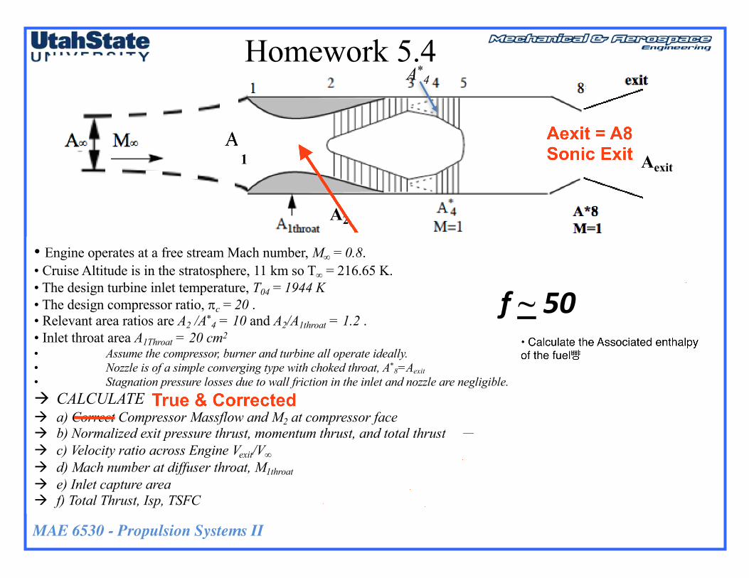
• Engine operates at a free stream Mach number, M∞ = 0.8. • Cruise Altitude is in the stratosphere, 11 km so T∞ = 216.65 K.• The design turbine inlet temperature, T04 = 1944 K • The design compressor ratio, pc = 20 . • Relevant area ratios are A2 /A*
4 = 10 and A2/A1throat = 1.2 . • Inlet throat area A1Throat = 20 cm2
• Assume the compressor, burner and turbine all operate ideally. • Nozzle is of a simple converging type with choked throat, A*
8=Aexit• Stagnation pressure losses due to wall friction in the inlet and nozzle are negligible. à CALCULATEà a) Correct Compressor Massflow and M2 at compressor faceà b) Normalized exit pressure thrust, momentum thrust, and total thrustà c) Velocity ratio across Engine Vexit/V∞à d) Mach number at diffuser throat, M1throatà e) Inlet capture areaà f) Total Thrust, Isp, TSFC
A*4
f~ 50

MAE 6530 - Propulsion Systems II
Homework 5.4 (2)
1
A2
Aexit
• Now allow an expandable Nozzle where, Aexit > A*8
à CALCULATEà a) Optimal expansion ratio for nozzle Aexit /A*
8à b) c) Velocity ratio across Engine Vexit/V∞à c) thrust, Isp, TSFC of optimal nozzle, à d) Assuming the same combustor temperature and inlet throat area as previous page
à At what compressor demand pc does the inlet throat choke ( @ A1throat )
à Plot the Compressor operating line à pc vs corrected massflow, f(M2) for 1 < pc < pc @ choke
à Plot the capture area A∞ vs corrected massflow, f(M2) for 1 < pc < pc @ choke
A*4