hvdc light cables for long distance grid connection · hvdc light cables for long distance grid...
TRANSCRIPT

1
HVDC Light Cables for long distance grid connection
Kenneth Johannesson, Anders Gustafsson, Johan Karlstrand, Marc Jeroense ABB AB, High Voltage Cables
Box 546, SE-37123 Karlskrona, Sweden [email protected], +46 455 55770
Summary HVDC Light cables have now been in service for more than a decade making it possible to transmit electric power over long distances at a reduced cost. These polymer cable systems have been developed, installed and are in service on systems up to 150 kV and 400 MW. The next step, 320 kV and 1100 MW, is now qualified and ready for market introduction. The main advantage of HVDC Light cables over their HVAC counterparts can be found in their reduced weight and dimensions. This results in a higher power density. The HVDC Light cables have lower losses and can therefore be designed smaller, both in weight and diameter. A HVAC cable system needs three cables, whereas a HVDC cable system only needs two. The HVDC transmission system improves transmission capability and the transmissions lengths are nearly unlimited due to the elimination of the capacitive currents. The first commercial HVDC Light cable system was installed in 1999 by connecting a wind park at the Gotland, an island in Sweden. Since then several other projects have been realized. The BorWin 1 project in the North Sea connecting a 150 kV, 400 MW wind farm is currently being installed. Today almost 1900 km of HVDC Light cables have been installed with another 520 km in production.
2
Introduction With the introduction of VSC (voltage source converter) stations and extruded polymeric HVDC (high voltage direct current) cables the traditional market for HVDC cable interconnections, i.e. long submarine links, is expanded and new market driven opportunities are realised. Currently three voltage levels exist, namely 80, 150 and 320 kV. However there exists no principal objection against intermediate voltage levels. The HVDC Light Cable System
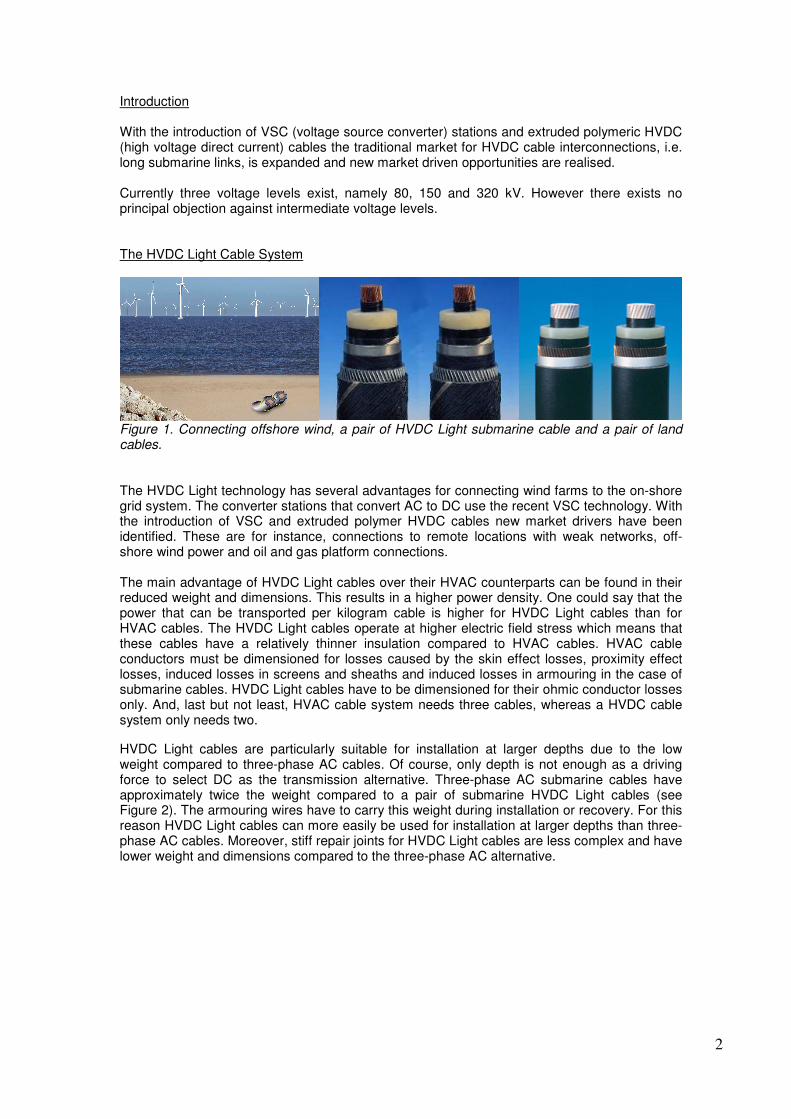
Figure 1. Connecting offshore wind, a pair of HVDC Light submarine cable and a pair of land cables. The HVDC Light technology has several advantages for connecting wind farms to the on-shore grid system. The converter stations that convert AC to DC use the recent VSC technology. With the introduction of VSC and extruded polymer HVDC cables new market drivers have been identified. These are for instance, connections to remote locations with weak networks, off-shore wind power and oil and gas platform connections. The main advantage of HVDC Light cables over their HVAC counterparts can be found in their reduced weight and dimensions. This results in a higher power density. One could say that the power that can be transported per kilogram cable is higher for HVDC Light cables than for HVAC cables. The HVDC Light cables operate at higher electric field stress which means that these cables have a relatively thinner insulation compared to HVAC cables. HVAC cable conductors must be dimensioned for losses caused by the skin effect losses, proximity effect losses, induced losses in screens and sheaths and induced losses in armouring in the case of submarine cables. HVDC Light cables have to be dimensioned for their ohmic conductor losses only. And, last but not least, HVAC cable system needs three cables, whereas a HVDC cable system only needs two. HVDC Light cables are particularly suitable for installation at larger depths due to the low weight compared to three-phase AC cables. Of course, only depth is not enough as a driving force to select DC as the transmission alternative. Three-phase AC submarine cables have approximately twice the weight compared to a pair of submarine HVDC Light cables (see Figure 2). The armouring wires have to carry this weight during installation or recovery. For this reason HVDC Light cables can more easily be used for installation at larger depths than three-phase AC cables. Moreover, stiff repair joints for HVDC Light cables are less complex and have lower weight and dimensions compared to the three-phase AC alternative.

3
0
20
40
60
80
1 00
0 20 0 40 0 60 0 80 0 100 0
P o w e r P [M W ]
Wei
gh
t [k
g/m
]
H V A C
H V D C
Figure 2. Approximate weight of three-phase submarine cables and a pair of HVDC Light submarine cables as a function of power. The exact numbers depend on installation conditions and cable design. Copper conductors have been used. In order to prove that HVDC Light cables are suitable for installation at large depths the following test has been conducted. A 300 mm2 copper conductor, 8 mm insulation, double steel armoured HVDC Light cable including a submarine flexible joint was subjected to a tensile bending test according to Electra No. 171. A force of 380 kN was used. The test corresponded to a laying depth of more than 2000 meters.
Figure 3. AC versus DC. The DC transmission system improves transmission capability and has lower losses. The HVDC Light cables have in principle no limit in length whereas HVAC cable has a limitation in length mainly depending on the capacitive charging current. The higher the AC voltage, the shorter the length.
AC Voltage (kV) Capacitive charging current (A) 66 410 132 600 220 720 400 1130
Table 1. Capacitive charging current for 100 km, 1000mm2, HVAC XLPE cables (50 Hz).
Distance
400 kV HVAC
132 kV HVAC
DC
AC
320kV HVDC Light
150kV HVDC Light
Power

4
As mentioned above the AC cables have high reactive charging currents and the maximum transmission length is therefore limited. The maximum length may be extended by using inductive shunt compensation; either controlled or not.
0
40
80
120
160
200
240
280
320
0 25 50 75 100 125 150 175 200 225 250
Length [km]
Po
wer
[MW
]
220 kV
HVDC-Light 300 MW
150 kV
132 kV
66 kV
Figure 4. Maximum lengths with tuned inductive shunt compensation in both ends. In Figure 4, an example is given, which shows the maximum lengths and ratings for XLPE cables and a 150 kV HVDC Light cable. Problems with high charging currents can be seen for the 132, 150 and 220 kV XLPE cables. For the 66 kV cable the voltage swing will become too large and for that reason a voltage problem will arise after approximately 100 km. With inductive tuned shunt compensation in both ends it is quite possible to transmit electrical power up to 100 km, also for large 400 kV XLPE cables. This extra equipment in both ends will of course have a negative impact on the total cost for the link, as well as for the energy losses. However, at a length above approximately 100 km, either unacceptable current or voltage problems may arise. Thus, the HVDC Light cable system is a very attractive solution for long distance grid connection. The HVDC Light cable is, as known, almost unlimited in length. Due to low losses and the elimination of charging currents, one may choose an aluminium conductor for HVDC Light cables also for high power transmission. Qualification The qualification of the HVDC Light cable system follows the CIGRE Recommendation “Recommendations for testing DC extruded cable systems for power transmission at a rated voltage up to 250 kV” published as CIGRE Technical Brochure No. 219. The qualification started with the 80 kV level, followed by the 150 kV level and the 320 kV level. The cable system consists of cables and related accessories for both land and sea installation. In Figure 5 a type test circuit is shown for a 320 kV with the actual test voltages according to the CIGRE Recommendation. A one-year prequalification test (usually called long term test) is also included in the CIGRE Recommendation. The HVDC Light 320 kV cable system has also passed this test.

5
Figure 5. Type test set-up of HVDC Light 320 kV cable system. A considerable amount of type tests have been performed since the 1990’s. More than 20 type tests have been performed on the 80, 150 and 320 kV levels on cable systems with different conductor sizes. Long term tests on 80, 150 and 320 kV levels have also been conducted. Today the extruded cable system HVDC Light relies on a solid base of laboratory and commercial experience. The latest level, 320 kV and 1100 MW, is qualified and ready for connecting new wind farms. A power map showing the delivered and qualified HVDC Light cable systems is shown in Figure 6.
Figure 6. Voltage, power and length [km] of HVDC Light cable systems. Future The future trends for extruded dc cable systems that we see, are higher power and for that reason higher voltages, larger depths and dynamic cables. Concerning higher voltages we will probably see a trend towards 500 or 600 kV and as such covering a power range up to 1500 and 2000 MW. HVDC Light cables are suitable for installation at larger depths due to their relative lower weight compared to the 3-phase ac alternatives. Also the stiff field and repair joints are less complex and weigh less. Another future trend we will see is cable connections from land to floating devices such as floating platforms for the oil and gas industry and floating wind mills.
terminations
joint
referencecable
terminations
joint
referencecable
14084212
359284
390
421
520
0
200
400
600
800
1000
1200
0 100 200 300 400
Voltage [kV]
Pow
er [M
W]
In operation & under realization
Commercially available
Extruded DC cable type test 320 kV (VSC mode) • Load Cycle Test o 12 cycles -592 kV, 8/16 hours heating/cooling o 12 cycles +592 kV, 8/16 hours heating/cooling o 3 cycles +592 kV, 24/24 hours heating/cooling • Superimposed Surge Voltage Test o Udc = +320 kV, Up2s
= +665 kV, 10 times o Udc = +320 kV, Up2o
= -375 kV, 10 times o Udc = -320 kV, Up2s
= -665 kV, 10 times o Udc = -320 kV, Up2o
= +375 kV, 10 times • Subsequent DC test o Udc = -592 kV, 2 hours

6
Installations The world’s first commercial extruded HVDC cable system was inaugurated on November 19, 1999 in Visby by the Swedish Minister for Environment Mr. K. Larsson. The event marks a major milestone in cable development as well as in transmission and distribution technology.
Figure 7. The first commercial HVDC Light cable system connecting a wind park on Gotland. The Gotland HVDC Light system transmits 50 MW by connecting a wind park at the southern tip of the island Gotland in Sweden with the city of Visby, also located on Gotland. The wind generated power is transmitted over a distance of 72 km to the load centre in the capital city of Visby. The system consists of two VSC stations and an extruded bipolar cable link. The system operates on 80 kV DC. Since then several other projects have been realized. The Estlink project, a 150 kV, 350 MW link, has been in successful operation since 2006. The BorWin 1 project in the North Sea connecting a 400 MW wind farm is currently being installed.
Figure 8. The BorWin 1 project in the North Sea connecting a 400 MW wind farm. When it commences operations in September 2009, Bard will be the largest and most remote offshore wind farm in the world located 128 km off the German mainland in the North Sea. BorWin1 will deliver up to 400 MW of emissions-free electricity to the German power grid via an HVDC Light power transmission system. Bard consists of 80 wind turbines, each with a generating capacity of 5 MW. ABB was selected by the grid operator E.ON Netz / Transpower

7
to supply a complete HVDC Light solution to connect the wind farm to the AC power transmission network.
Figure 9. The photos above views the landfall of North Sea and the two 150 kV HVDC Light Cables, 1600mm2 copper conductor, for the BorWin 1 project. AC power from the 80 wind turbines will run to an AC platform from which two parallel 170 kV three-core HVAC submarine cable will deliver the power 1 km to an offshore converter station platform. There the power will be converted to DC and transmitted in two 1200 mm2, +/-150 kV HVDC Light submarine cables to the island of Norderney, where they will be jointed to two 1600 mm2 submarine cables. The submarine route is 128 km. Those cables will run to a transition point onshore where they will be connected to two 2300 mm2 HVDC Light underground cables, which will transmit the power a distance on land of 75 km to the converter station at the Diele substation. At Diele the power will be converted to AC and fed into the E.ON 380 kV transmission grid. Today almost 1900 km of HVDC Light cables have been installed with another 520 km in production. Already, during the first 10 years, the installed length of HVDC Light cables is larger than the MI (mass impregnated) cables installed during 60 years. Nevertheless, the service experience is excellent.
Figure 10. By 2009 a total of 1900km of HVDC Light cable will be installed and in service. References
1. “HVDC Light cable system extended to 320 kV”, CIGRE 2008 Paper No. B1-304. 2. “Increased voltage for the HVDC Light product range – a complete solution”,
JICABLE07, Paper B.4.7. pp 425-430. 3. “The Murraylink project – the first commercial 150 kV extruded HVDC cable system”,
JICABLE03, Paper A.7.4. pp 217-222. 4. “The development of an extruded HVDC cable system and its first application in the
Gotland HVDC Light project”, JICABLE99, Paper B.7.5. pp 538-542.
0200400600800
100012001400160018002000
1998 1999 2002 2004 2006 2009
Kilo
met
ers
in s
ervi
ce