hvac noise control - pdhonline.com · the mechanical systems which control temperature, humidity,...
TRANSCRIPT

PDHonline Course M335 (8 PDH)
Commercial HVAC
2012
Instructor: A. Bhatia, B.E.
PDH Online | PDH Center5272 Meadow Estates Drive
Fairfax, VA 22030-6658Phone & Fax: 703-988-0088
www.PDHonline.orgwww.PDHcenter.com
An Approved Continuing Education Provider

www.PDHcenter.com PDH Course M335 www.PDHonline.org
Commercial HVAC
A. Bhatia, B.E.
Overview
Commercial air-conditioning or HVAC (Heating, Ventilation and Air Conditioning) refers to
the mechanical systems which control temperature, humidity, air flow, and air quality in
homes and commercial buildings. HVAC refrigeration equipment is generally sized in tons or
Btu per hour and the heating equipment is specified in kW or Btu per hour. Each
refrigeration ton equals to the heat extraction rate of 12,000 Btu per hour.
A HVAC conditioning system includes more than just the air conditioning unit itself. A
complete system also includes the air distribution system (ductwork, dampers, grilles and
registers), hydronic/refrigerant piping and the temperature and schedule control system.
Each of these components makes an important contribution to the performance and
efficiency of the system as a whole. In order to operate efficiently, a system needs to be
properly sized and installed. Oversized units cost more to operate and do a poor job of
comfort control, and poor installation can dramatically reduce the as installed efficiency of the
system. The controls are also an integral part of the system and should include
programmable thermostats and timers for scheduling of air conditioning equipment or a
computerized energy management systems (EMS).
HVAC systems also make up approximately 50% of energy usage in commercial and
residential buildings. A relatively small improvement in system design, equipment selection
or control strategies can mean greater comfort, lower first costs, easier equipment
maintenance, and large long-term savings in energy expenditures over the life cycle of the
system. Here are three major factors to keep in mind before investing in a commercial HVAC
system:
© A. Bhatia Page 2 of 118
HVAC Systems: The HVAC components may be assembled into systems literally dozen or
hundred different ways, and the choice largely depends on cost, aesthetics and degree of
control. Choosing a system with a lower lifecycle cost will have a much bigger impact on

www.PDHcenter.com PDH Course M335 www.PDHonline.org
your bottom line than choosing the lowest-priced equipment. Taking into account projected
expenses such as annual energy usage, installation and maintenance cost, repairs and
financing along with the initial cost of the equipment, will help you determine the actual
financial impact of your system.
HVAC components - Understand the type of components your HVAC system uses and
determine whether it will give you the option to upgrade to more efficient components later.
Energy star labeled equipment help reduce energy costs considerably over a standard
efficiency system while providing a high level of performance. HVAC rooftop units are now
available with efficiency ratings up to 16.1 SEER, 14.3 EER and 16.4 IPLV; systems with a
higher IPLV rating can help reduce energy use year-round, especially during spring and fall
when only part-load operation is needed. Many regional utilities offer rebates to make high-
efficiency equipment more attractive to commercial customers.
Control systems: Investigate advanced control systems to take your comfort control to a
higher level. The control systems make it possible to improve energy efficiency, simplify
troubleshooting, even monitor and control a wide range of fire and life safety systems,
access and security control technology, lighting equipment and maintenance management
programs on the same network. Look for a control system that offers open protocol options
such as LonTalk® and BACnet® to take advantage of increased integration with other
building systems.
This course provides an overview of above criteria in detail and is divided in 3 modules:
Section -1 HVAC Systems
Section -2 HVAC System Components
Section -3 HVAC Control System Equipment and Control Loops
© A. Bhatia Page 3 of 118
______________________________________________________________________
www.PDHcenter.com PDH Course M335 www.PDHonline.org
SECTION -1 HVAC SYSTEMS
The most common air-cooling systems are either direct expansion (DX) type or the chilled
water type.
DIRECT EXPANSION (DX) SYSTEMS
In direct expansion (DX) systems, the air is cooled with direct exchange of heat with
refrigerant passing through the tubes of the finned cooling coil. All these systems comprise
of a hermetic sealed or open compressor/s, evaporator (cooling coil fabricated out of copper
tubes and aluminum fins), a supply air blower, filter, a condenser and heat rejection
propeller fan. These come in two types:
Unitary System – The most common types of DX systems are unitary air conditioners and
heat pumps. “Unitary” refers to the fact that all of the components necessary to heat, cool,
dehumidify, filter and move air are included in one or more factory-made assemblies. Since
all equipment is prepackaged, the installation cost is usually lower, and the performance
quality is often higher than field-erected systems. Unitary equipment is available as single
package or as split systems.
Single package units include all of the necessary functions and components in one package
that is installed outside the building. Window air-conditioners, package units are typical
example of unitary DX systems.
• Room air conditioner (capacity range of 0.5 to 3 TR per unit, suitable for an area of
not more than 1000 square feet).
• Packaged unit integral air-cooled condenser (capacity range of 3 to 50 TR, suitable
for a maximum an area of 1000 – 10000 square feet).
© A. Bhatia Page 4 of 118
Split System – A split system is a combination of an indoor air handling unit (fan and
cooling/heating coils) and an outdoor condensing unit (condenser and compressor). Unitary
split equipment includes heat pumps and air conditioners with integral or separate gas or
electric heating systems. Heat pumps provide both heating and cooling from the same unit
and are the most efficient devices. Air conditioners provide cooling only and must be
supplemented with either an internal electric or gas-heating coil or with a totally stand-alone

www.PDHcenter.com PDH Course M335 www.PDHonline.org
heating system. Split-systems are typically found in residential and small commercial
installations with capacity ranges varying 1 to 50 TR and suitable for an area of 100 – 10000
square feet. The new ductless systems which can be conveniently mounted on the ceiling or
wall are in this family.
Performance Ratings Terms for Unitary Equipment
• SEER – The Seasonal Energy Efficiency Ratio is a representation of the cooling
season efficiency of a heat pump or air conditioner in cooler climates. It applies to
units of less than 65,000 Btuh capacity. The higher the SEER rating, the more
efficient the AC system operates.
• EER – The Energy Efficiency Ratio is a measure of a unit’s efficiency at full load
conditions and 95 degrees outdoor temperatures. It typically applies to larger units
over 65,000 Btuh capacity.
• HSPF – The Heating Season Performance Factor is a representation of the heating
efficiency of a heat pump in cooler climates.
• Btuh – Btuh or Btu/h is a rate of heating or cooling expressed in terms of British
Thermal Units per Hour.
• Ton – One ton of cooling is the energy required to melt one ton of ice in one hour.
One ton = 12,000 Btuh
Efficiency Ratings of Unitary Equipment
Federal law mandates a minimum efficiency of 10 SEER for unitary equipment of less than
65,000 Btuh capacity. The American Society of Heating, Refrigeration and Air Conditioning
Engineers (ASHRAE) recommend 10 EER for equipment between 65,000 and 135,000
Btuh. ASHRAE standard 90.1 recommends other efficiencies for larger equipment. It is often
cost effective to pay for more efficient equipment. For example, upgrading from a 10 SEER
to a 12 will reduce cooling costs by about 15 percent. Upgrading from a 10 to a 15 reduces
cooling costs by about 30 percent.
© A. Bhatia Page 5 of 118
CHILLED WATER SYSTEMS

www.PDHcenter.com PDH Course M335 www.PDHonline.org
In a chilled water system, liquid water is pumped throughout the building to “chilled water
coils”. Since the liquid water needs to be at a cold temperature, a “cooling plant” is required.
The plant is typically referred to as a chiller plant. These are usually pre-packaged by the
manufacturer with the evaporator and condenser attached, so that only water pipes and
controls must be run in the field.
Chilled water systems are further categorized as air-cooled or water cooled system
depending on how the heat is rejected out of the system. The chilled water system is also
called central air conditioning system. This is because the chilled water system can be
networked to have multiple cooling coils distributed through out a large or distributed
buildings with the refrigeration equipment (chiller) placed at one base central location.
Chilled water systems are typically applied to the large and/or distributed areas. Capacity
ranges from 20- 2000 TR and are suitable for an area of 3000 square feet and above.
AIR CONDITIONING SYSTEM DESIGN CONFIGURATIONS
The air-conditioning components and equipments may be designed and assembled in
literally dozen or hundred different ways but in practice these are broadly classified into
three categories:
1. Centralized Ducted “All – Air” Systems - These are systems in which the primary
movement of heat around the building is via heated and cooled air. These systems are
the most common in large spaces such as office buildings, common public areas, retail,
shopping, manufacturing areas, airports, hotel lobbies etc.
2. Centralized Fluid Based Hydronic Systems - These are systems in which a fluid -
typically water but possibly refrigerant - is used to move heat around the building. These
systems are fairly common in office rooms, hotel rooms, schools, building perimeter
control etc.
© A. Bhatia Page 6 of 118
3. Decentralized Systems - These are systems in which heating and cooling is conducted
locally, with little or no bulk movement of heat around the building. Individual unit
ventilators are dispersed in small rooms and around perimeter of a building. These
systems are relatively common in schools, small hotels, domestic applications,
residential homes and small offices.

www.PDHcenter.com PDH Course M335 www.PDHonline.org
The boundaries between these system types are not absolute, but they form useful
categories within which to put the many different systems. The choice largely depends on
the following -
1. System constraints - Cooling load, zoning requirements, acceptable tolerance to
temperature/humidity, degree of control etc
2. Architectural Constraints - Size and appearance of terminal devices, acceptable noise
level, Space available to house equipment and its location relative to the conditioned
space, acceptability of components obtruding into the conditioned space
3. Financial Constraints - Capital cost, Operating cost, Maintenance cost
We will review some of the options and issues under each of these categories.
ALL – AIR SYSTEMS
In an ‘All-Air system’, the refrigerant or chilled water is used to cool and dehumidify the air in
the air handling unit (AHU). The cool air is then circulated throughout the building thru the
ductwork. Heating can also be accomplished either by hot water or electrical strip heaters.
The centralization of these systems allow for better management and system operation. On
the other hand, they also require either a mechanical room adjacent to the controlled space
for locating the AHU and large ductwork in building space.
The diagram below indicates the main components of a typical air-conditioning system.
© A. Bhatia Page 7 of 118

www.PDHcenter.com PDH Course M335 www.PDHonline.org
Typical air-conditioning system
This is an air-based system, which is the most dominant air-conditioning type for large
buildings. Fresh air is drawn into the building through the intake louver, mixed with return air,
heated or cooled to a controlled temperature, circulated around the building and provided to
the occupied space. Local temperature control is provided by a terminal reheat unit attached
to a temperature controller within the occupied space. Exhaust air is extracted from the
space and dumped to the outside. In general, the majority of the return air is recycled via the
return air duct. The individual components of this system are:
1. Air Handling Unit – This is a cabinet that includes or houses the central furnace, air
conditioner, or heat pump and the plenum and blower assembly that forces air through
the ductwork.
2. Intake louvers - These are the external louvers through which supply air is drawn into
the building. Intake is generally equipped with volume control damper to regulate the
amount of fresh air and economizing the quantity of outside air during favorable outside
conditions.
3. Filters - These are used to remove particles of dust or dirt from the supply air.
© A. Bhatia Page 8 of 118
4. Heating coils - These heat up the incoming airstream using coils through which hot
water is passed or banks of electric heating elements.

www.PDHcenter.com PDH Course M335 www.PDHonline.org
5. Cooling coils - These cool the incoming airstream using coils through which refrigerant
or water is passed.
6. Supply fans - These are used to circulate the air through the network of ductwork.
7. Ductwork – It is a branching network of round or rectangular tubes generally
constructed of sheet metal, fiberglass board, or a flexible plastic and wire composite
material located within the walls, floors, and ceilings. The three most common types of
duct material used in home construction are metal, fiberglass duct board, and flex-duct.
8. Supply Ductwork - These carry air from the air handler to the rooms in a house.
Typically each room has at least one supply duct and larger rooms may have several.
9. Return Ductwork – These carry air from the conditioned space back to the air handler.
Most houses have only one or two main return ducts located in a central area.
10. Supply and Return Plenums- These are boxes made of duct board, metal, drywall or
wood that distribute air to individual ducts or registers.
11. Terminal reheat heating coils- These use hot water coils or electric heating elements
to heat up the air being supplied to one part of the building according to the temperature
in that space.
12. Supply and extract grilles - These are the points at which the air is either supplied into
or extracted from the space, and may be ceiling-mounted or wall-mounted. Also called
diffusers or registers.
13. Boots- These connect ductwork to registers.
14. Extract fans - These are used to extract the air from the space and discharge it to
outside.
© A. Bhatia Page 9 of 118
15. Return air duct - These are interconnections between inlet and outlet ductwork
sections, which let a controlled amount of air recirculate around the air conditioning
system when full fresh air is not required.

www.PDHcenter.com PDH Course M335 www.PDHonline.org
16. Exhaust louvers - These are the external louvers through which extract air is
discharged from the building.
CENTRALIZED AIR CONDITIONING SYSTEMS
© A. Bhatia Page 10 of 118
System Pros System Cons
1. The central plant is located in
unoccupied areas, hence facilitating
operating and maintenance, noise
control and choice of suitable
equipment.
2. No piping, electrical wiring and filters
are located inside the conditioned
space.
3. Allows greater energy efficiency by
using greater amount of outside air
during of favorable seasons instead of
mechanical refrigeration.
4. Seasonal changeover is simple and
readily adaptable to climatic control.
5. Gives a wide choice of zonability,
flexibility, and humidity control under all
operating conditions.
6. Heat recovery system may be readily
incorporated.
7. Allows good design flexibility for
optimum air distribution, draft control,
and local requirements.
1. Requires additional duct clearance
which can reduce the usable floor space.
2. Air-balancing is difficult and requires
great care.
3. Accessibility to terminals demands close
cooperation between architectural,
mechanical and structural engineers.

www.PDHcenter.com PDH Course M335 www.PDHonline.org
System Pros System Cons
8. Well suited to applications requiring
unusual exhaust makeup.
9. Infringes least on perimeter floor space.
10. Adapts to winter humidification.
11. Are more energy efficient than
decentralized systems.
TYPES OF “ALL-AIR” SYSTEMS
There are three major types of Centralized Ducted Air Systems:
1. Constant Volume Systems
2. Dual Duct Systems
3. Variable Volume Systems
CONSTANT VOLUME SYSTEMS (CAV)
Constant volume systems deliver a constant volume of air and responds to changing
thermal loads by varying air temperature. The air volume is usually based on the design
cooling load for the given zone. The ducting and air handling system are sized to match the
heat gain from equipment, lights, exterior, and people. Typical applications include:-
1. Space with uniform loads (small office buildings, manufacturing plants, retail etc.)
© A. Bhatia Page 11 of 118
2. Small spaces requiring precision control

www.PDHcenter.com PDH Course M335 www.PDHonline.org
System Description
Constant volume systems are common form of air-conditioning of single thermal zones and
are often the system of choice due to simplicity, low cost and reliability. Air is drawn from
outside, filtered and then heated or cooled as required. A supply fan then distributes the air
through a ductwork network to supply grilles in the space. Air is drawn from the space via
extract grilles. The air is then recycled via the return air duct or discharged to the outside
through external discharge louvers.
Constant Volume System
Normally, the equipment is located outside the conditioned space but can also be installed
within the conditioned are if conditions permit.
Controls Configurations
Most CAV systems are small, and serve a single thermal zone. One air handling system is
required for each zone because there can be only one supply air temperature at any given
time. Air temperature can be varied in the air handling unit to meet the sensible heating or
cooling requirement of the zone.
© A. Bhatia Page 12 of 118
For the typical system serving multiple zones, not all zones will need full cooling at the same
time due to unequal loading. For example the perimeter areas with different solar exposures
will see different loads through out the day, while the interior zones will see a fairly constant

www.PDHcenter.com PDH Course M335 www.PDHonline.org
load. Because the system cannot vary the supply air volume to each zone, some zone air
handling systems will have to supply warmer air to maintain the space setpoint. This is
achieved by terminal reheat. The terminal reheat units are controlled by a thermostat in the
occupied space and apply heating to adjust the air supply temperature to that required to
maintain comfortable conditions in the room. This arrangement provides for simple control
but is very inefficient, as the supply air is often both cooled and heated, resulting in energy
waste.
Constant Volume System with Reheat
Alternative control arrangement for CAV system serving multiple zones is the use of “Bypass
box”. In this arrangement a bypass box with motorized relief damper is added to the branch
duct serving a zone. In response to the zone thermostat signal, the relief damper discharge
part of cool air to the open return ceiling thereby restricting the amount of cold air supply to
the zone. This is more energy efficient way compared to reheat arrangement but is typically
applied on open return above false ceiling.
© A. Bhatia Page 13 of 118

www.PDHcenter.com PDH Course M335 www.PDHonline.org
Constant Volume System with Bypass Box
Effectiveness and Internal Comfort
Constant volume systems are the simplest to install, but all areas receive a preset
percentage of the cooling all the time. However, loads can vary dramatically: the number of
people, appliances and lights, and solar gain through the windows are unpredictable. With
this system, only the area near the thermostat is satisfied all the time. Everyone else is
either too hot or too cold.
One path around this problem is to locate the main thermostat in the area with the highest
cooling load. Areas requiring less cooling can then have their air flows reheated. This
however is a highly energy inefficient method and is prohibited by many codes. One energy
efficient system for retrofit or new construction is the variable air volume (VAV). In this
system, the quantity of air is reduced to zones with reduced cooling requirements. We will
discuss this further in following paragraphs.
© A. Bhatia Page 14 of 118
As a generic rule, for the office areas, large interior zones can be provided with constant
volume systems (apply VAV system for perimeter zones). Similarly for shopping corridors,
hotel lobbies, airport concourse can have constant volume systems whereas for individual
shops, hotel rooms etc should have individualized VAV controls.

www.PDHcenter.com PDH Course M335 www.PDHonline.org
Energy Saving Considerations
Constant volume, variable temperature systems use more fan work than VAV systems
because they are usually designed for a larger design supply air flow rate, and they cannot
modulate the supply air flow rate during part load conditions. The following are some
considerations outlined in ASHRAE STD 90.1-1999. The numbers in brackets refer to Std.
90.1-1999 sections.
1. Equipment must be scheduled off automatically during unoccupied hours [6.2.3.1].
2. Adjustment of economy cycle operation to ensure maximum gains are made from the
use of fresh air for "free" cooling. Demand Controlled Ventilation is required for systems
with at least 3,000 CFM of outdoor air and occupant density greater than 100 people per
1,000 ft2 [6.2.3.9].
3. Air- or water-side economizers are required. There are several exceptions to this rule,
particularly when dealing with heat recovery [6.3.1].
4. Where humidification is required to maintain humidity above 35°F dewpoint, water-side
economizers must be used when economizers are required. Introducing large amounts
of cool, dry air while meeting the sensible cooling load adds significantly to the humidifier
load. Process loads, including hospitals, are exempt [6.3.2.4].
5. Energy recovery is required for systems with at least 5,000 CFM supply air and a
minimum of 70% outdoor air. This is specifically aimed at schools and labs [6.3.6.1].
6. For systems under 20,000 CFM, constant volume fans are limited to 1.2 hp/1,000 CFM.
For systems over 20,000 CFM, fans are limited to 1.1 hp/1,000 CFM [6.3.3.1].
CONSTANT VOLUME SYSTEMS
© A. Bhatia Page 15 of 118
System Pros System Cons
1. Easy to design and install
2. Dedicated unit per zone offers good
1. Supply air volume cannot be varied.
2. Ducting is oversized and there is a

www.PDHcenter.com PDH Course M335 www.PDHonline.org
System Pros System Cons
temperature control and redundancy.
3. Air- or water-side economizers can be
added easily to the design to minimize
mechanical cooling during cooler
weather.
4. The main air handling systems can
accommodate the ventilation air,
avoiding dedicated ventilation
equipment.
5. Constant volume systems have
relatively few moving parts and thus
can operate with a reasonable level of
reliability.
significant fan power penalty.
3. Varying the supply air temperature does
not guarantee dehumidification.
4. Many small systems are needed, each
requiring access to the zone it serves.
5. Rooftop and self-contained systems offer
limited cooling diversity among different
zones.
6. The control of terminal reheat units is
another source of problems. The
operation of the thermostat and the valve
controlling the terminal reheat unit
(where a hot water coil is used) needs
regular checking and calibration to
ensure that good quality control is
maintained.
DUAL DUCT SYSTEM
© A. Bhatia Page 16 of 118
Dual or double duct system is an air conditioning system in which cold and warm air is
circulated throughout a building via two parallel ducts. Hot air flows within one duct, cold air
within the other. The proportion of hot and cold air delivered to each room within the building
may be controlled by thermostatically operated dampers on the ducts outlet. The system is
well suited to provide temperature control for individual spaces or zones. Common
applications include:

www.PDHcenter.com PDH Course M335 www.PDHonline.org
• Office Buildings
• Institutional
System Description
Dual Duct Constant Air Volume System
Dual-duct all-air systems use two ducts, the first supplying warm air and the second
supplying cold air. Air is mixed at the terminal serving the individual space, so that supply air
of the desired temperature is delivered to the space. Dual-duct systems are uncommon in
new buildings.
Controls Configurations
© A. Bhatia Page 17 of 118
There are a number of ways in which a dual-duct system can be controlled. For a typical
system serving multiple zones, the air is divided into two, with one supply duct being heated
(the "hot deck") and the other cooled (the "cold deck"). In the simplest form of control, the
hot deck operates at maximum supply temperature, which is around 84-86oF, while the cold
deck operates at minimum supply temperature, which is around 50-55oF. A thermostat in the
occupied space controls a mixing box which adjusts the balance of hot and cold air being

www.PDHcenter.com PDH Course M335 www.PDHonline.org
supplied, to maintain comfortable conditions. The ultimate in control for a system of this type
is to adjust the hot and cold deck temperatures on a continuous basis to match the heating
and cooling needs of the building.
Effectiveness and Internal Comfort
Dual-duct systems can provide a good quality of servicing but are expensive to install. The
quality of temperature control is mainly limited by the way in which rooms are grouped
together for temperature control. Often multiple rooms or even the entire face of a building
may be served as a single space with only one point of temperature control. This can cause
discomfort if individual rooms within this space have different amounts of equipment or
sunlight.
DUAL DUCT SYSTEMS
© A. Bhatia Page 18 of 118
System Pros System Cons
1. Only the required amount of supply air
is used, so fan power is not wasted.
2. Systems with terminal volume
regulation are self-balancing.
3. Zoning of central equipment is not
required.
4. Instant temperature response is
achieved because of simultaneous
availability of cold and warm air at
each terminal unit.
5. No seasonal changeover is necessary.
6. There is no simultaneous heating and
cooling. Heat in plenum air can be
1. Initial cost is usually higher than other
VAV systems. Two ducting systems and
two air handling units add to cost.
2. Does not operate as economically as
other VAV systems.
3. Introducing the correct volume of outdoor
air into the building is more difficult.
4. Providing each zone with the correct
amount of outdoor air is more difficult.
5. More sophisticated controls are required.
6. Large duct shafts from centralized air
handling systems are required.
7. Dual-duct systems have critical moving

www.PDHcenter.com PDH Course M335 www.PDHonline.org
System Pros System Cons
used as reheat.
7. Fixed cold air supply temperature
maintains humidity control in space.
8. Air- or water-side economizers can be
added easily to the design to avoid
mechanical cooling during cooler
weather.
9. The main air handling systems can
accommodate the ventilation air,
avoiding dedicated ventilation
equipment.
parts in the form of the mixing boxes.
The operation of the mixing boxes
requires regular maintenance to ensure
that the overall performance of the
system is maintained.
As with other air-based systems, the
balancing of air-flows around the system is
critical to the system operation. Regular
rebalancing of air-flows is highly
recommended to maintain performance.
VARIABLE AIR VOLUME SYSTEMS (VAV)
Variable air volume system (VAV) delivers a constant temperature of air and responds to
changing thermal loads by varying the quantity of supply air.
Conditioned spaces in buildings are primarily divided into two categories: (1) Perimeter
zone, where there are external wall, roofs, and windows and space load varies depending
on solar heat, outdoor-indoor temperature difference and internal load; and (2) Interior zone
where space loads are mainly internal loads. In an interior zone, the air system often
operates at cooling mode in both summer and winter. To account for load variations (in
perimeter and interior zones), VAV system varies the air volume in response to the varying
load to maintain predetermine space parameter and conserve fan power.
© A. Bhatia Page 19 of 118
VAV systems are very common for a wide range of applications. Common applications
include:

www.PDHcenter.com PDH Course M335 www.PDHonline.org
1. Office Buildings
2. Schools
System description
The simplest VAV system incorporates one supply duct which distributes approximately
55ºF supply air. Each branch duct to individual zones having varied load requirements are
equipped with VAV unit. Because the supply air temperature is constant, the air flow rate is
varied to meet the rising and falling heat gains or losses within the thermal zone served.
Variable Air Volume System
Variable air volume system with terminal reheat
Variable air volume (VAV) systems use variable volume terminal units or boxes to vary the
airflow in each zone or space in accordance to the thermostat signals within the space.
Heating is turned on when the air flow reaches a predetermined minimum. If more cooling is
required, more cold air is introduced into the space.
© A. Bhatia Page 20 of 118
In the best implementation of these systems, the central air handling unit fan speed is
controlled to maintain a constant duct pressure. An interlock is arranged between the supply
and extract fans. Variable air volume systems are very common in larger office buildings.

www.PDHcenter.com PDH Course M335 www.PDHonline.org
Controls configurations
Variable air volume (VAV) with reheat systems provide conditioned air to each zone at a
constant temperature, typically 55°F. The amount of air varies to match the heat gain from
equipment, lights, exterior and people. At part load conditions, VAV systems supply only the
necessary amount of conditioned air to each zone, saving significant fan energy.
A zone temperature sensor is used to control a damper that is arranged to maximize air-flow
when heating or cooling loads are high and cut down to minimum air when loads are low.
When more dampers close, the duct system static pressure increases. The primary supply
fan adjusts to maintain duct static pressure using discharge dampers (FC fans only), inlet
guide vanes, or variable frequency drives (VFDs). Control of the system's fan capacity is
critical in VAV systems. Without proper and rapid flow rate control, the system's ductwork, or
its sealing, can easily be damaged by over-pressurization. Automatic controls for the fan
generally comprise of a speed modulating control to the fan motor to maintain a constant
pressure in the supply duct. However, in some systems, variable volume control may be
achieved by other methods, such as a damper restricting the flow or the adjustment of fan
blades.
The control of supply duct temperature is similar to that of a constant volume system. In
many buildings, the air in the supply duct is heated or cooled to a constant temperature of
typically 14-16oC. The terminal reheat units are controlled by a thermostat in the occupied
space and apply heating to adjust the air supply temperature to that required to maintain
comfortable conditions in the room. Because the airflow is variable, this simple control
arrangement does not produce the inefficiencies present in constant volume systems. More
complex control of duct temperature is feasible, following the same "hi select" methods as
described for constant volume systems. However, as long as the minimum air-flow in the
system is substantially smaller than the maximum airflow, and the variable volume
components of the system are operating correctly, additional control complexity is not
necessary.
Effectiveness and internal comfort
© A. Bhatia Page 21 of 118
VAV systems provide very good control and a high level of flexibility in operation. The
internal comfort control is generally good, but there can be problems when air flows are low.
www.PDHcenter.com PDH Course M335 www.PDHonline.org
In particular, there may be problems with ensuring that adequate fresh air is supplied to
individual zones and also low flows of air mix poorly with the air in the room and instead
drop directly from the supply diffuser, causing discomfort for anyone sitting immediately
below. There can also be problems with air "whistling" past the variable volume dampers
under certain conditions. However this can be offset by setting the VAV boxes to provide a
minimum amount of air, even if that amount exceeds cooling requirements. While this
maintains air turnovers and minimum outdoor air ventilation rates, the zone may be
overcooled and reheat may be required, resulting in simultaneous heating and cooling.
ASHRAE Standard 90.1-1999 requires the minimum supply air volume be the ventilation
rate for the zone for most applications.
A properly functioning variable air-volume system is very efficient because it has minimal
simultaneous heating and cooling and low fan energy.
Type of Variable air volume terminal units
There are generally five different types of units that are used: pressure-independent volume
units; pressure-dependent, airflow-limiting, maximum volume units; pressure-dependent
units; bypass (dumping) units; and supply outlet throttling units. One other type of unit that is
used is the fan-powered variable air volume terminal unit.
1. Pressure – Independent Units - Pressure-independent volume units regulate the flow
rate in response to its respective thermostat's call for heating or cooling. The thermostat
controls airflow to the space by varying the position of a simple damper or volume
regulating device located in the unit. The required flow rate is maintained, regardless of
the fluctuation of the system pressure being supplied by the air handling unit supply fan.
These units can be field- or factory-adjusted for maximum and minimum airflow settings.
© A. Bhatia Page 22 of 118
2. Pressure Dependent-Airflow Limiting Maximum Volume Units - A pressure-
dependent, airflow-limiting, maximum volume unit regulates maximum volume, but the
flow rate will oscillate when system pressure varies. These units are less expensive than
pressure-independent units. These units can be used where pressure independence is
required only at maximum airflow, where system pressure variations are relatively small,
and where some degree of fluctuation or "hunting" is tolerable.

www.PDHcenter.com PDH Course M335 www.PDHonline.org
3. Pressure Dependent Units - Pressure-dependent units do not regulate the flow rate,
but position the volume regulating device in response to the thermostat. These units are
the least expensive and should only be used where there is no need for maximum or
minimum airflow control and the air handling unit system pressure is stable.
4. Bypass Dumping Units - Generally, in small air handling systems, the cost of a variable
air volume system is too high. However, by using bypass (dumping) units in certain
zones or spaces, the constant volume system can have variable airflow control. The
thermostat controls airflow to the space by varying the position of the volume regulating
device. If less air is required to the space, the regulating device closes down and
bypasses or diverts some of the air to the return ceiling plenum or return air duct. This
technique is very effective for constant volume systems.
5. Supply Outlet Throttling Units - Supply outlet throttling units are usually linear
diffusers. The area of the throat or the discharge opening varies in approximate
proportion to the air volume to maintain throw patterns. The thermostats are usually
located at the outlet of the diffuser for easy temperature adjustment. Since these units
are pressure-dependent, constant pressure regulators are usually required in the duct
system. Noise is a concern when using these units in occupied spaces.
6. Fan Powered Variable Air Volume Units - Fan-powered variable air volume units are
available in two types: parallel and series flow units. The units have the same
components as pressure-dependent or pressure-independent volume units, and in
addition, a fan and usually an electric or hot water heating coil. Fan-powered variable air
volume units, both series and parallel, are often used for building perimeter heating,
because they move more air through a room at low cooling loads and during the heating
cycles compared to variable air volume reheat or perimeter radiation systems.
Energy Considerations
Varying the supply air volume reduces fan work, a major use of building energy. The
following are some considerations outlined in ASHRAE Std 90.1-1999. The numbers in
brackets refer to Std. 90.1-1999 sections.
© A. Bhatia Page 23 of 118
1. Equipment must be scheduled off automatically during unoccupied hours [6.2.3.2].

www.PDHcenter.com PDH Course M335 www.PDHonline.org
2. Demand Controlled Ventilation is needed for systems with at least 3,000 CFM of outdoor
air and an occupant density greater than 100 people per 1,000 ft2 [6.2.3.9].
3. Where humidification is needed to maintain humidity above 35°F dewpoint, water-side
economizers must be used when economizers are needed. Introducing large amounts of
cool, dry air while meeting the sensible cooling load adds significantly to the humidifier
load. Process loads, including hospitals, are exempt (6.3.2.4). • For systems under
20,000 CFM, VAV is limited to 1.7 hp/1,000 CFM. For systems over 20,000 CFM, VAV
systems are limited to 1.5 hp/1,000 CFM [6.3.3.1].
4. 30 hp and larger fan motors must use no more than 30% of design power at 50% airflow
[6.3.3.2].
5. Energy recovery is required for systems with at least 5,000 CFM supply air and a
minimum of 70% outdoor air. This is specifically aimed at schools and labs [6.3.6.1].
VARIABLE AIR VOLUME SYSTEMS
© A. Bhatia Page 24 of 118
System Pros System Cons
1. Only the necessary amount of primary
air is used, conserving primary fan
power.
2. Diversity is applied to supply air
volume, reducing duct and fan sizes.
3. Capital cost is lower since diversities of
loads from lights; occupancy, solar and
equipment of as much as 30% are
permitted.
4. Virtually self-balancing.
5. It is easy and inexpensive to subdivide
into new zones and to handle
1. Difficult to consistently maintain
minimum outdoor air quantities entering
the building.
2. Difficult to consistently maintain the
correct amount of outdoor air in each
zone.
3. Requires sophisticated controls.
4. Simultaneous heating and cooling
occurs once the minimum air volume is
reached in a zone.
5. A separate, distributed heating system is

www.PDHcenter.com PDH Course M335 www.PDHonline.org
System Pros System Cons
increased loads with new tenancy or
usage if load does not exceed the
original design simultaneous peak.
6. No zoning is required in central
equipment.
7. Lower operating cost because fans run
long hours at reduced volume
8. Refrigeration, heating and pumping
matches diversity of loads
9. Unoccupied areas may be fully cut-off
10. Allows simultaneous heating and
cooling without seasonal changeover
11. Air- or water-side economizers can be
added easily to the design to minimize
mechanical cooling during cooler
weather.
12. Air handling unit can maintain
minimum outside air amounts, avoiding
the need for dedicated ventilation
equipment.
needed for cooler climates.
6. The variable volume dampers, either as
VAV boxes in the ceiling space or as
variable volume diffusers, can be
maintenance-intensive items. A variable
volume system with poorly functioning
variable volume functions is in essence
just a constant volume system. As a
result, regular maintenance and
calibration of variable volume equipment
is essential for good system
performance.
7. If the air supply volume to different
spaces falls out of adjustment, then
individual rooms and sometimes even
entire floors can become quite
uncomfortable and the system can
become inefficient.
8. The control of terminal reheat units is
another source of potential hazards. The
operation of thermostats and the valve
controlling the terminal reheat unit needs
regular checking and calibration to
ensure that good quality control is
maintained.
© A. Bhatia Page 25 of 118
CENTRAL FLUID BASED HYDRONIC SYSTEMS

www.PDHcenter.com PDH Course M335 www.PDHonline.org
Central fluid based hydronic systems use terminal units to condition the air. The term
hydronic refers to an air-conditioning system that uses water for distribution of heat. Cooling
and dehumidification is provided by circulating chilled water through a finned coil in the unit
whereas heating is provided by supplying hot water through the same or a separate coil.
Why Fluid based Systems?
1. Water has greater specific heat and density compared to air and therefore water can
convey a lot of heat per unit volume. The distribution elements (pipes) are typically
smaller than that of air distribution ductwork.
2. Zone control is easy and the individual equipment can be shut off during not occupied
hours. Typical application is the hotel rooms and multiple small zones.
3. Fluid based systems require small primary air for ventilation purposes. The system relies
on 100% recirculation air and there is no return air system.
4. The power required to pump water through the building is usually less than the fan
power needed for supply air and return air systems.
5. The fluid based system in combination with provision for ventilation air can match
versatility of all-air systems. Positive ventilation, central dehumidification, winter
humidification, and good temperature control over a number of control zones are
capable with the system.
Centralized fluid-based systems come in a variety of radically different forms. Key types of
fluid-based system are:
1. Hydronic system (All – Water System)
2. Fan-coil system
3. Induction system
4. Variable Refrigerant Volume system (VRV)
© A. Bhatia Page 26 of 118
5. Hybrid system (using both all-fluid and all-water arrangement)

www.PDHcenter.com PDH Course M335 www.PDHonline.org
‘ALL – WATER’ HYDRONIC SYSTEMS
In an all-water hydronic system, the hot or cold-water is distributed to individual heat transfer
devices (terminal units) located in each room of the building. When heating, the terminal
units draw heat from the water and when cooling these reject heat to the water. The biggest
drawback of all-water hydronic system is the difficulty in providing adequate indoor air
quality. Due to this concern, these systems should not be applied to the occupied areas and
are ideally suited for machinery rooms, substations etc.
An All-Water system uses the following basic components:
1. The use of a chiller (on roofs or plant rooms) to cool the water which would be circulated
via circulating pumps to the terminal units (example fan coil units) located in the
occupied space.
2. The use of boilers (in plant rooms) to heat the water which would be circulated via
circulating pumps to the terminal units located in the occupied space. Hydronic heating
systems employ a variety of terminal units that include fan coil units, baseboard
radiators, convectors, unit heaters, and radiant floors.
Hydronic systems are designated by how the seasonal switch over from heating to cooling
occurs. The hydronic system piping can be arranged in 3 basic configurations: (1) Two-pipe
system, (2) Three-pipe system and (3) Four-pipe system.
© A. Bhatia Page 27 of 118
Two Pipe Systems

www.PDHcenter.com PDH Course M335 www.PDHonline.org
Two pipe systems consist of a network of insulated pipes; one pipe supplies chilled water
and the second pipe returns it to the chiller. The secondary water is cold in summer and
intermediate seasons and warm in winter. With water-changeover, chilled water is
circulated during the cooling season and hot water during the heating season. The problems
occur during the mid-seasons where cooling can be required part of the time and heating
part of the time and no heating or cooling the rest of the time.
Two pipe systems without water-changeover circulate chilled water only and provide heat
where it is needed by electric strip heat at the terminal units. In some cases, hot water is
circulated during the coldest part of the heating season to reduce operating cost.
The primary air quantity is fixed and the primary air temperature control is achieved by
varying the water supply through the coil. When thermostat sensor demand more cooling,
the two or 3-way valve located on the line is full open position.
TWO-PIPE SYSTEM
© A. Bhatia Page 28 of 118
System Pros System Cons
1. Usually less expensive to install than
four pipe systems
1. Less capable of handling widely
varying loads or providing widely
varying choice of room temperature
than four-pipe systems

www.PDHcenter.com PDH Course M335 www.PDHonline.org
System Pros System Cons
2. Cumbersome to change over and the
problem is acute on the shoulder
months (spring and fall) when the
occupants need heat in the cool
mornings and cooling in the warmer
afternoons.
3. Though it is economic initially on first
cost, it is more costly to operate than
four-pipe systems.
Three- Pipe System
In the three pipe system, hot water and chilled water are fed to each fan coil, with a common
return. This is somewhat more expensive than 2-pipe system, since a third pipe must be run
to each unit. Since the hot water and cold water are mixed in the return, these inefficient
systems are seldom installed today.
© A. Bhatia Page 29 of 118

www.PDHcenter.com PDH Course M335 www.PDHonline.org
Four-Pipe System
In the four pipe system, the chilled water loop and the hot water loop are completely
separate. While these systems are most expensive to install, they are easier to operate in
unpredictable climates.
The system is further categories as the independent load system and common load
systems.
1) Independent load systems have two separate water coils, one served by hot water, the
other by cold water. The systems make use of 2-way on-off valve.
2) Common load systems can have a single coil in the air handler but still supplied
independently with 4-pipe system. The systems make use of 3-way diverting valves.
Note that the water flow rate required for heating is much lower than the chilled water flow. It
is better to use 4-pipe system, which allows the use of smaller size piping and pumps for
lower hot water flow rates.
© A. Bhatia Page 30 of 118
FOUR-PIPE SYSTEM

www.PDHcenter.com PDH Course M335 www.PDHonline.org
System Pros System Cons
1. All year availability of heating and
cooling with individual zone temperature
control
2. Chilled and hot water could be
simultaneously supplied during the
Spring and Fall seasons
3. Elimination of zoning cost and
complexity
4. Simpler changeover decisions (No
summer-winter changeover and primary
air reheat schedule)
5. The lowest and quietest fan speed is
adequate most of the time.
6. More flexible and adaptable to widely
varying loads
1. Four-pipe systems have a high first
cost due to the second water system
and the need for either two coils or
more costly control valves at each
terminal unit.
2. The systems also have a high
operating cost due to the two pumps
operating (though provide good
flexibility in meeting varying loads)
HYBRID SYSTEMS
Hybrid systems use both air and water (cooled or heated in central plant room) distribution
to room terminals to perform cooling or heating function. Unlike all-water system, this
system ensures ventilation air in the spaces so that indoor air quality is not sacrificed.
Air Portion of the System
© A. Bhatia Page 31 of 118
The air side is comprised of central air conditioning equipment, a duct distribution system,
and a room terminal. The supply air, called primary air, usually has a constant volume which

www.PDHcenter.com PDH Course M335 www.PDHonline.org
is determined by the need for outside (fresh) air for ventilation. When in cooling mode the
primary air is dehumidified, to provide comfort and prevent condensation, by a central
conditioning unit. In the winter, heating mode, the air is humidified, by the central
conditioning unit, to limit dryness.
Water Portion of the system
The water side consists of a pump and piping to convey water to heat transfer surfaces
within each conditioned space. The water used can be chilled by direct refrigeration, by
using chilled water from a primary cooling system, or by heat transfer through a water-to-
water exchanger. Chillers usually supply chilled water anywhere from 35-48°F. Individual
room temperature control is by regulation of either the water flow through it or the air flow
over it. In the winter, the heating capacity of the coil in a conditioned space must be great
enough to heat the space and offset the cool primary air, which is provided.
HYBRID SYSTEMS
© A. Bhatia Page 32 of 118
System Pros System Cons
1. Flexible and readily adaptable to many
building module requirements.
2. Provides individual room control.
3. The power required to pump water
through the building is usually less
than the fan power needed for supply
air and return air systems.
4. Very good control is available over
many zones.
5. Heating and Cooling can be available
for all zones allowing variation of
loads.
1. No positive ventilation is provided unless
wall openings are used.
2. No humidification is provided.
3. Seasonal change over is required.
4. Maintenance and service work has to be
done in the occupied areas.
5. Design of between season operations is
crucial as a result of the low primary air
delivered.
6. Terminal unit filters must be changed
often due to secondary airflow.

www.PDHcenter.com PDH Course M335 www.PDHonline.org
System Pros System Cons
6. Space needed for distribution system
is minimal.
7. Energy saving are achieved by using
water instead of air to deliver heating
and cooling to the space.
8. Cross contamination is reduced
because recirculation occurs within
rooms.
FAN COIL UNITS
A fan coil conditioner unit is a type of room terminal unit that can be used with water-only
(all-water) or air-water systems. In the air-water system the fan-coil conditioner unit provides
the heating or cooling to a space while the primary air system supplies all ventilation.
System description
© A. Bhatia Page 33 of 118

www.PDHcenter.com PDH Course M335 www.PDHonline.org
Fan-Coil Unit using 4-way piping for heating and cooling along with 2-way and 3-way diverter valve for temperature control
A fan-coil unit is relatively simple air-conditioning equipment that is placed at each place
which needs to be heated or cooled. The fan-coil conditioner consists of a fan, filter and coil.
The fan draws in room air and passes it through the filter and then by the coil to either heat
or cool it and then returns it to the room to control the temperature and particulates. The
coils have chilled water or low temperature hot water (LTHW) passing through them, which
is supplied at a central location. Where there is a single coil this can be arranged to provide
heating and/or cooling according to requirements. Where there are two coils, one is
arranged to provide heating and the other cooling. This configuration is referred to as a four-
pipe fan-coil unit (as shown in schematic above).
The fan units are available in various configurations that can be either wall mounted or
ceiling mounted. Variations may take the form of two-pipe fan-coil units, with a single cooling
or heating coil, or may use an electrical heating coil in place of a LTHW coil. Auxiliary air
may be delivered to the conditioned space for dehumidification and ventilation purposes.
Units are available in standard capacities of 200, 300, 400, 600, 800, and 1200 CFM.
© A. Bhatia Page 34 of 118
Design Recommendations

www.PDHcenter.com PDH Course M335 www.PDHonline.org
In order to make a proper fan coil unit selection, the whole air conditioning system must be
looked at because sizing a fan coil unit is not just matching the room load. Other criteria
which must be considered during selection are; the minimum room load, fresh air
requirements, with or without reheat, 2 or 4-pipe system, zone size, flexibility and maximum
noise level in the room, etc.
The cooling capacity which is supplied to the room is the sum of cooling energy available in
the primary air and the cooling capacity of the fan coil unit. The way the primary air is
supplied to the room determines a great part of the required fan coil cooling capacity.
The most common methods to supply primary air are shown in the figures below:
© A. Bhatia Page 35 of 118
Applications Schematic
System-1: This is the most energy efficient
system. Primary air is supplied directly into
the room and the recirculation diffuser is
ducted to the inlet of the fan coil unit. For this
case the cooling energy available in the
primary air can be deducted from the room
load. An additional benefit with this
configuration is the fan coil unit can be
switched off in situations where primary air
only is sufficient to maintain the required
room conditions or when ventilation only is
required.
System-2: Primary air is supplied directly
into the room and recirculation air is taken
from the ceiling void. This is basically the
same as system-1; however the cooling
capacity must be higher because the
temperature in the ceiling void is normally

www.PDHcenter.com PDH Course M335 www.PDHonline.org
Applications Schematic
higher than in the room.
System-3: Primary air and recirculation air
are both ducted to the intake of the fan coil
unit. For this case, the entering air for the
heat exchanger is lower in temperature and
less humid than at system-1. The required
cooling capacity from the fan coil unit is
equal to system-1, however the air volume
must be higher to supply both the primary
and fan coil capacities of system-1.
System-4: Primary air is ducted to the intake
of the fan coil unit and recirculation air is
taken from the ceiling void. This is basically
the same as system-3; however the cooling
capacity must be higher because the
temperature in the ceiling void is normally
higher than in the room.
When primary air is supplied near the intake of the fan coil unit, part of the primary air will be
lost directly into the exhaust system wasting conditioned air energy. This is wasting energy
and should be avoided.
© A. Bhatia Page 36 of 118
To demonstrate the difference in energy consumption, an analysis is indicated below:

www.PDHcenter.com PDH Course M335 www.PDHonline.org
Controls configurations
Automatic controls for the fan-coil unit generally comprise of an ON-OFF control to the fan
motor, often in conjunction with three speed settings. A remote room temperature sensor is
used to control both the fan motor and modulating valves on the heating coil and the cooling
coil, and or three speed setting control to the fan motor.
Effectiveness and internal comfort
Fan-coil units provide excellent comfort levels for individual areas. With the temperature
sensor located in the space, the heating or cooling provided by the fan-coil unit can be
tempered according to the needs of the individual space.
Units with an outdoor air supply combine good temperature control with the ability to meet
requirements for fresh air to be supplied to the space.
The fault most often identified in relation to fan-coil units relates to noise, as the fan is close
to the occupied space. However, with a well-designed unit with a quiet fan and good sound
attenuation this does not need to be an issue.
Maintenance and Balancing Considerations
© A. Bhatia Page 37 of 118
The fan-coil unit is a free-standing unit and thus balancing is not required except if a ducted
system is used to provide fresh air to the units. Balancing and commissioning of any ducted
fresh air system may need adjustment, possibly affecting the output from the unit or the
comfort in the space. The LTHW heating circuit or the chilled water circuit may need re-

www.PDHcenter.com PDH Course M335 www.PDHonline.org
balancing or re-commissioning if indicated by poor performance of the unit in either cooling
or heating mode.
Typically fan-coil systems have a large number of thermostats. Regular calibration of these
thermostats is necessary.
If a fan-coil unit has a filter, this needs to be cleaned regularly as otherwise the air-flow may
be reduced, which in turn affects the ability of the unit to properly heat and cool the occupied
space.
Energy Saving Opportunities
The key areas for energy savings are:
1. Thermostats need to be calibrated regularly. In open-plan offices, poor calibration can
cause adjacent units to "fight", with one unit heating and the other cooling.
2. Filters need to be cleaned regularly.
3. Fan-coils work well with hybrid ventilation systems. Interlocks can be arranged between
the fan-coil unit in a space and the windows in the space, such that the unit switches off
when the window is opened. This avoids the fan-coil unit heating or cooling the space
when significant outdoor air is being introduced.
FAN COIL UNITS
© A. Bhatia Page 38 of 118
System Pros System Cons
1. Individual room temperature control.
2. Separate sources of heating and
cooling for each space available as
needed to satisfy a wide range of load
variations.
3. Low distribution system space required
as a result of reducing the air supply by
1. Limited to perimeter space.
2. The primary air supply is usually
constant with no provision for shutoff.
3. Not applicable to spaces with high
exhaust requirement.

www.PDHcenter.com PDH Course M335 www.PDHonline.org
System Pros System Cons
use of secondary water for cooling and
high velocity air design.
4. Reduced size of central air handling
equipment.
5. Dehumidification & filtration performed
in a central plant room remote from
conditioned space.
6. Outdoor air supply is positive.
7. Zoning of central equipment is not
required.
4. Seasonal changeover is necessary.
INDUCTION UNITS
The inducting system is designed for use in perimeter rooms of multi-storey, multi-room
building that may have reversing sensible heat characteristics. It is especially adapted to
handle the loads of skyscrapers with minimum space requirements for mechanical
equipment. Induction units are usually installed at a perimeter wall under a window. Some
hotel rooms are provided with induction coils.
System description
© A. Bhatia Page 39 of 118
Induction units are effectively a variant of a fan-coil unit. Instead of using a fan, primary air is
injected into the unit at high velocity from nozzles, which induces a secondary air flow from
the conditioned space - hence the name. The induced air flows over a cooling or heating coil
to provide room temperature control.

www.PDHcenter.com PDH Course M335 www.PDHonline.org
Induction unit
In an induction system, ducted primary air is fed into a small plenum chamber where it is
delivered through nozzles as high velocity jets. This induces secondary air from the room
across the secondary coil. The right quantity of high pressure air is adjusted automatically in
response to a thermostat located in the conditioned space. If the primary air alone provides
sufficient temperature control, then an internal damper in the unit causes the induced
secondary air to bypass the coil. Otherwise the induced air is heated or cooled through the
coil.
Induction units are served by hot water and/or chilled water which is generated by central
plant. Variations may take the form of two-pipe induction units, with a single cooling or
heating coil, or may use an electrical heating.
Induction units are comparatively rare and not used in new installations.
Controls Configuration
© A. Bhatia Page 40 of 118
Automatic controls for the induction unit comprise operation of the internal damper and/or
heating and cooling coils according to a remote temperature sensor located in the space.
The temperature of the primary air may also be varied according to the external ambient
temperature or season.
www.PDHcenter.com PDH Course M335 www.PDHonline.org
Effectiveness and internal comfort
Induction unit installations can provide good comfort levels due to the individual room
temperature control provided. Fresh air is also supplied to the space by the units.
Due to the increased air velocity from the primary air jet nozzles some noise may be
generated by the induction units. With careful design this noise can be controlled to an
acceptable level. The plenum is usually acoustically treated to attenuate part of the noise
generated in the duct system and in the unit.
Energy saving opportunities
The energy savings opportunities for induction units are:
1. Room thermostats need to be calibrated regularly. Poor calibration may lead to
overheating or overcooling which will waste energy.
2. Regular cleaning and adjustment of the primary air jet nozzles is important for the
effective operation of the induction unit.
3. Air filters must be cleaned regularly
INDUCTION UNITS
© A. Bhatia Page 41 of 118
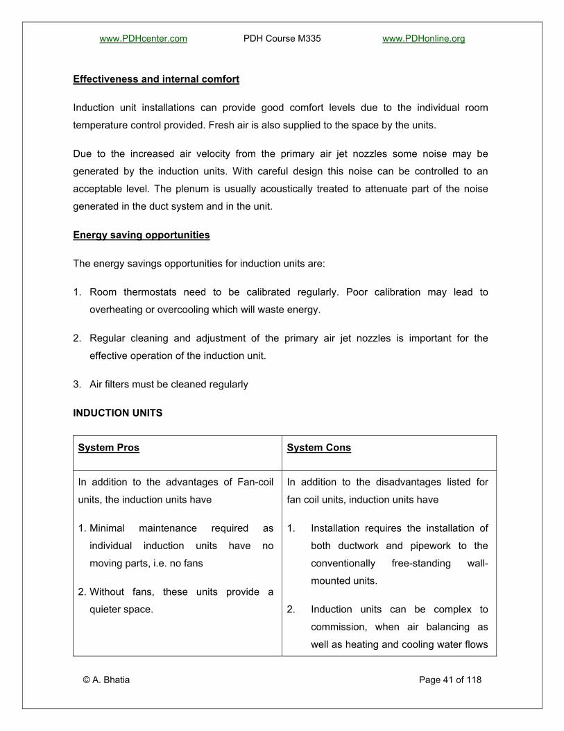
System Pros System Cons
In addition to the advantages of Fan-coil
units, the induction units have
1. Minimal maintenance required as
individual induction units have no
moving parts, i.e. no fans
2. Without fans, these units provide a
quieter space.
In addition to the disadvantages listed for
fan coil units, induction units have
1. Installation requires the installation of
both ductwork and pipework to the
conventionally free-standing wall-
mounted units.
2. Induction units can be complex to
commission, when air balancing as
well as heating and cooling water flows

www.PDHcenter.com PDH Course M335 www.PDHonline.org
System Pros System Cons
must be correctly set.
3. The primary air supply is usually
constant with no provision for shutoff.
4. Higher energy consumption due to
increased power required by the
primary pressure drop in the terminal
units.
5. Controls tend to be more complex than
for all-air systems.
6. Initial cost is usually higher than fan
coil systems.
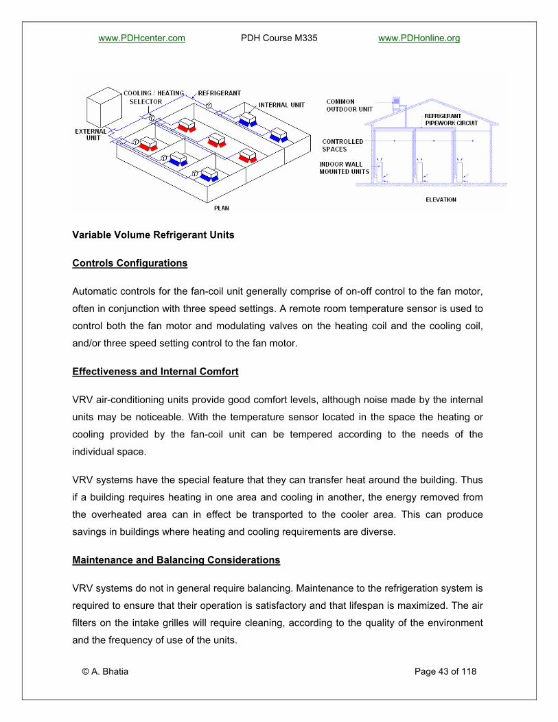
VARIABLE REFRIGERANT VOLUME SYSTEMS
In a VRV system, refrigerant runs around the building to individual fan-coils that can provide
heating or cooling as required.
System description
© A. Bhatia Page 42 of 118
Variable refrigerant volume (VRV) units comprise a number of room units which share a
common refrigerant circuit, served from a common outdoor unit. Each of the room units can
either heat or cool depending on how the refrigerant is used within the coil. Indoor units
should be relatively near to one another, and the distance to the common outdoor unit kept
to a minimum. The indoor units are similar in their operation to the split system air-
conditioning unit.
www.PDHcenter.com PDH Course M335 www.PDHonline.org
Variable Volume Refrigerant Units
Controls Configurations
Automatic controls for the fan-coil unit generally comprise of on-off control to the fan motor,
often in conjunction with three speed settings. A remote room temperature sensor is used to
control both the fan motor and modulating valves on the heating coil and the cooling coil,
and/or three speed setting control to the fan motor.
Effectiveness and Internal Comfort
VRV air-conditioning units provide good comfort levels, although noise made by the internal
units may be noticeable. With the temperature sensor located in the space the heating or
cooling provided by the fan-coil unit can be tempered according to the needs of the
individual space.
VRV systems have the special feature that they can transfer heat around the building. Thus
if a building requires heating in one area and cooling in another, the energy removed from
the overheated area can in effect be transported to the cooler area. This can produce
savings in buildings where heating and cooling requirements are diverse.
Maintenance and Balancing Considerations
© A. Bhatia Page 43 of 118
VRV systems do not in general require balancing. Maintenance to the refrigeration system is
required to ensure that their operation is satisfactory and that lifespan is maximized. The air
filters on the intake grilles will require cleaning, according to the quality of the environment
and the frequency of use of the units.

www.PDHcenter.com PDH Course M335 www.PDHonline.org
Energy Saving Opportunities
The key areas for energy savings are:
1. Regular maintenance to the refrigeration unit will improve both efficiency and
effectiveness.
2. Cleaning of air intake filters is essential to maintain both performance and efficiency.
3. VRV units work well with hybrid ventilation systems. Interlocks can be arranged between
the VRV air-conditioning unit in a space and the windows in the space, such that the unit
switches off when the window is opened. This avoids the unit heating or cooling the
space when significant outdoor air is being introduced.
DECENTRALIZED SYSTEMS
Decentralized systems are small air conditioner units that provide cooling only where
needed rather than the entire space and these essentially cool small rooms. These are
essentially direct expansion (DX) systems, which operate using direct expansion of
refrigerant in the finned tubes across the air path.
Decentralized systems are often used as after hours support for centralized systems,
allowing specific areas to be air-conditioned without requiring the operation of central plant.
In such applications, both the central system and the decentralized units are sized to cool
the particular conditioned space adequately without the other operating. In other
applications, where decentralized units are added to supplement an inadequate existing
system, they are selected and sized to meet the required capacity when both systems
operate.
In smaller buildings, these are less expensive to operate than central units, even though
their efficiency is generally lower than that of central air conditioners. Smaller room air
conditioners (i.e., those drawing less than 7.5 amps of electricity) can be plugged into any
15- or 20-amp, 115-volt household circuit that is not shared with any other major appliances.
Larger room air conditioners (i.e., those drawing more than 7.5 amps) need their own
dedicated 230-volt circuit.
© A. Bhatia Page 44 of 118
The major types of decentralized systems are:

www.PDHcenter.com PDH Course M335 www.PDHonline.org
1. Split Systems
2. Window Units
3. Heat Pumps
All these comprise of a hermetic sealed compressor/s, evaporator (cooling coil fabricated
out of copper tubes and aluminum fins), a supply air fan, filter and a condensing unit. These
are essentially the factory assembled self-contained units and are also known as local
systems.
SPLIT SYSTEMS
As the name suggests, the split systems are individual systems in which the two heat
exchangers are separated (one outside, one inside). The indoor unit (evaporator) consists of
a direct expansion (DX) cooling coil, filter and fan whereas the outdoor unit (condensing
unit) contains one or more reciprocating/rotary compressors, a condenser and a fan. The
evaporator and the condensing unit are connected by refrigerant piping.
System description
Split system air-conditioning units comprise internal and external units linked by refrigerant
pipework. The refrigerant compressor, installed in the outdoor unit, pumps the refrigerant
through the indoor unit and the outdoor unit arranged in closed loop. The refrigerant picks
the heat from the indoor unit (evaporator coil), and rejects energy to the outside atmosphere
as it goes through the outdoor unit (condensing coil). Energy rejected is the sum of the
energy taken indoors plus the energy consumed by the compressor in pumping the
refrigerant through the refrigerant circuit.
© A. Bhatia Page 45 of 118
The indoor unit fan pulls or pushes air around the outer surfaces of the coil inside the indoor
unit, taking warm air from the room and injecting cooled air into the room in summer. The air
passing through the indoor unit is cooled; say to 60°F, before re-circulated back to the room.

www.PDHcenter.com PDH Course M335 www.PDHonline.org
Split system air-conditioning units
Indoor units can be wall mounted or ceiling mounted. Recessed ceiling mounted units are
often referred to as "cassette" type units. Refrigeration pipework will comprise liquid and gas
pipelines, of unequal sizes, and may be restricted in length, requiring careful location of the
indoor and outdoor units for larger buildings. The outdoor unit can be roof mounted, wall
mounted or fixed directly to the ground.
Split unit is a choice in applications, which require interior zone cooling. Remember, a
window unit require outside exposure for heat rejection and cannot be used for interior
rooms.
Controls configurations
Split system air-conditioning units provide good individualized control. A hand held remote
controller is often provided, linked to a wall unit with thermostat temperature control. The fan
of the indoor unit may have two or three speeds to give some modulation of heat or cooling
output. The split system may be reversible, operating as a heat pump to provide heating to
the space. Alternatively an electric heating element is used to provide heating.
© A. Bhatia Page 46 of 118
With the temperature sensor located in the space the heating or cooling provided by the fan-
coil unit can be tempered according to the needs of the individual space.
www.PDHcenter.com PDH Course M335 www.PDHonline.org
Maintenance and balancing considerations
Split system air-conditioning units are free-standing and independent and thus balancing is
not an issue. Maintenance to the units is required to ensure that their operation is
satisfactory and that lifespan is maximized. The air filter on the intake grille will require
cleaning, according to the quality of the environment and the frequency of use of the units.
The use of split systems for large areas can cause excessive maintenance costs due to the
large number of moving parts - each split system has its own compressor and a sealed
refrigerant system.
WINDOW UNITS
Window-mounted air conditioners cool the individual conditioned spaces. A window unit is
an encased assembly designed primarily for mounting in a window, through a wall, or as a
console. These units are designed for comfort cooling and to provide delivery of conditioned
air to a room without ducts. They include a prime source of refrigeration, dehumidification,
means for circulating and cleaning air, and may also include means for ventilating, and/or
exhausting and heating.
They are cheap and easy to install, being fitted into windows or through walls. They are
quite common in small, mid-grade suburban office space, older institutional buildings and
accommodation blocks.
They have a low initial cost and are quick and easy to install.
System description
© A. Bhatia Page 47 of 118
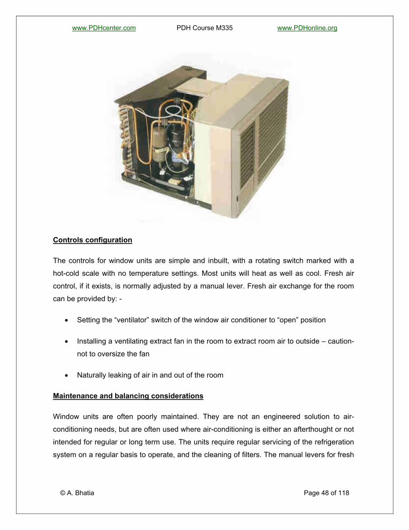
Window units are simple refrigerate coolers packaged into a single box that produces cool
air on one side and rejects hot air on the other. These require outside exposure for heat
rejection and cannot be used for interior rooms. Split unit option shall be used in such
places. The refrigerant compressor now is part of the machine locating at the window area.
Since this compressor gives out most noise, among other components, the window unit will
make the room acoustically inferior to other air conditioning systems.
www.PDHcenter.com PDH Course M335 www.PDHonline.org
Controls configuration
The controls for window units are simple and inbuilt, with a rotating switch marked with a
hot-cold scale with no temperature settings. Most units will heat as well as cool. Fresh air
control, if it exists, is normally adjusted by a manual lever. Fresh air exchange for the room
can be provided by: -
• Setting the “ventilator” switch of the window air conditioner to “open” position
• Installing a ventilating extract fan in the room to extract room air to outside – caution-
not to oversize the fan
• Naturally leaking of air in and out of the room
Maintenance and balancing considerations
© A. Bhatia Page 48 of 118
Window units are often poorly maintained. They are not an engineered solution to air-
conditioning needs, but are often used where air-conditioning is either an afterthought or not
intended for regular or long term use. The units require regular servicing of the refrigeration
system on a regular basis to operate, and the cleaning of filters. The manual levers for fresh

www.PDHcenter.com PDH Course M335 www.PDHonline.org
air-control sometimes become casualties to age and rough handling, which can lead
unwanted fresh air flow. There are no balancing considerations for this system.
HEAT PUMPS
A heat pump is a device that acts as an air conditioner in the summer and as a heater in the
winter. Heat pumps look and function exactly like an air conditioner except it has a
reversible cycle. It contains a 4-way reversing valve that lets it switch between "air
conditioner" and "heater."
A cooling only system cools the indoor air but a heat pump provides cooling in summer
season and heating in winter season. A supplementary electric resistance heater may also
be used to assist the heat pump at lower outdoor temperatures. In colder climates, heat
pumps require a defrost period. During defrost times the electric heater is the only means of
heating the interior of the building. These units are manufactured as either split or packaged
systems.
Heat pumps for air conditioning service may be further classified as:
Air-to-Air Heat Pumps
The air-to-air heat pump is the most common type of heat pumps. It is particularly suitable
for factory-built unitary heat pumps, and has been widely used for residential and
commercial application. Air is used as the heat source and heat sink. Extended surface,
forced convection heat transfer coils are normally employed to transfer the heat between the
air and the refrigerant. When selecting or designing an air-source heat pump, two factors in
particular must be taken into consideration:
1. The variation in temperature experienced in a given locality.
2. The formation of frost
Water-source Heat Pumps
© A. Bhatia Page 49 of 118
The water-source heat pump uses water and air as the heat source or heat sink depending
on the mode of operation. When cooling, water is used as the heat sink, and the heat pump

www.PDHcenter.com PDH Course M335 www.PDHonline.org
operates as a water-cooled air conditioner. When heating, water is used as the heat source
and the equipment operates as a water chiller.
The water-source heat pump is suitable for many types of multi-room buildings, including
office buildings, hotels, schools, apartment buildings, manufacturing facilities and hospitals.
Heat Pump Efficiency
Because heat pumps move heat rather than generating heat, these can provide up to 4
times the amount of energy they consume. If you heat with electricity, a heat pump can trim
the amount of electricity you use for heating by as much as 30% to 40%. High-efficiency
heat pumps also dehumidify better than standard central air conditioners, resulting in less
energy usage and more cooling comfort in summer months.
The measurement of heating efficiency of a heat pump is the coefficient of performance
(COP). It is the ratio of heat output to electricity input using the same units (BTUH or kW). A
heat pump delivers from 1½ to 3½ units of heat for every unit of electricity it uses; saves
from 30 to 60 per cent electric heating bills, depending on the geographic location and
equipment used. COP of a heat pump is generally greater than 1. Heat output of a heat
pump, in terms of BTUH per kWh, is a product of its COP and a factor of 3400 (e.g. if the
COP of a heat pump is 1, then its heat output would be 1x 3400=3400 BTUH per kWh).
The heating efficiency of a heat pump may also be measured using a rating known as HSPF
(Heating Season Performance Factor). This rating is obtained by multiplying the COP of a
heat pump by a factor of 3.4.
Advantages
1. Affords opportunity for energy conservation by recovering heat from interior zones
and/or waste heat and by storing excess heat from daytime cooling for night time heating
2. No wall openings required.
3. Longer expected life than air-cooled heat pumps.
© A. Bhatia Page 50 of 118
4. Lower noise level because condenser fans are eliminated.

www.PDHcenter.com PDH Course M335 www.PDHonline.org
5. Energy for the heat pumps can be metered directly to each tenant.
6. Total life cycle cost frequently compares favorably to central systems when considering
relative installed cost, operating costs, and system life.
Disadvantages
1. Space required for boiler, heat exchanger, pumps and heat rejecter.
2. Higher initial cost than for most other multiple-packaged unit systems.
© A. Bhatia Page 51 of 118
3. Reduced airflow can cause the heat pump to cycle cutout. Good filter maintenance is
imperative.

www.PDHcenter.com PDH Course M335 www.PDHonline.org
SECTION -2 HVAC SYSTEM COMPONENTS
A heating, ventilation and air-conditioning (HVAC) system may be defined as an assembly
of components with a particular structure and a defined function. There are literally dozen or
hundred of ways in which basic HVAC components may be assembled into systems. In the
following pages we review the operation and use of a range of components.
Chillers
Chillers are a key component of most centralized air-conditioning systems. The function of a
chiller is to generate chilled water, which is distributed to large spaces for cooling. The two
principal types of chiller are air-cooled and water cooled. Compared to water, air is a poor
conductor of heat and therefore air-cooled chillers are larger and less efficient. The typical
condensing temperature for an air-cooled chiller is 120°F as opposed to a 105°F in a
comparable water condensed chiller. Air-cooled chillers also operate at higher compressor
ratios – which mean less cooling per watt energy consumption.
Air cooled chillers are generally located outside the building and reject heat directly to the
atmosphere, while water cooled chillers are generally located within the building and use
cooling towers located outside the building to reject the heat.
Circumstances favoring Air-cooled Systems
Air cooled chillers are favored over the water cooled systems under following circumstances:
1. Where water is scarce or quality water is not available
2. Where the system is not required to operate 24 hours.
3. Where the system is not to be located in or around noise restricted areas
4. Where there is adequate and accessible roof top or ground space for the system
equipment
5. Where sitting of cooling tower is restricted due to Legionella risk minimization
constraints.
© A. Bhatia Page 52 of 118
6. Where air-conditioning requirement is less than 200 TR

www.PDHcenter.com PDH Course M335 www.PDHonline.org
7. There may be statutory requirements for health and safety that may not permit use of
cooling towers in certain areas.
8. A high humidity climatic condition in the tropical areas where the effectiveness of the
cooling towers is significantly reduced.
Circumstances favoring Water-cooled Systems
Water-cooled chillers are generally favorable over the air-cooled systems under the
following circumstances:
1. Where the system is required to operate 24 hours.
2. Where there is limited roof top or ground space for the system equipment
3. Where noise minimization and aesthetics are of relative importance
4. Larger system capacity requirement typically above 200 TR.
The present trend leans towards the use of air-cooled condensers. Results from recent
generic studies on comparative life cycle costs of air cooled and water cooled systems
indicate that each system is considered to be more favorable than the other over a certain
range of plant capacity. As a guide, conclusions could be generalized and summarized as
follows:
Capacity Range (TR) Favorable System
40 to 200 Air-cooled chilled water system (explore the pros and
cons of using multiple DX systems if possible)
200 and above Water-cooled chilled water system
© A. Bhatia Page 53 of 118
Chiller Types

www.PDHcenter.com PDH Course M335 www.PDHonline.org
Different types of chiller are also used depending upon the type of compressor used as part
of the refrigeration circuit. The different types of compressor are as follows:
1. Reciprocating:
Reciprocating compressors are categorized as positive displacement machines. These
are available in two basic types: hermetic sealed units and units of open construction. In
hermetic sealed units, the motor and the compressor are direct-coupled and housed in a
single casing that is sealed to the atmosphere. In open construction units, the motor and
the compressor are in separate housings. In general, open construction units have a
longer service life, lower maintenance requirements and higher operating efficiencies.
The hermetic sealed units are most common particularly in small capacities. Single
stage reciprocating machines have an ability to operate at compression ratios of 10 to
12.
The capacity control in reciprocating machine is achieved through ‘On-Off’ or ‘Loading-
Unloading’ of compressor cylinders.
Reciprocating machines are manufactured in capacities from 0.5 to 150 TR.
The main factors favoring reciprocating machine is low cost. The other advantage is that
multiple reciprocating machines can be installed to closely match the building loads.
Multiple units allow flexibility to operate machines per the need. If properly managed this
could attribute to significant energy savings during low loads.
A major drawback is a high level of maintenance requirement’s, noise and vibration.
Since the capacity is limited to 150 TR, multiple units cost more than other options.
Multiple chiller configurations require large space and consume more energy per ton of
refrigeration.
© A. Bhatia Page 54 of 118
2. Rotary Screw:
Rotary or screw chillers, like reciprocating machines are positive displacement
compressors. Rotary is a wider term that may include vane, eccentric, gear or screw
types. The commercial refrigeration installation rely more on screw machines. Screw
compressors are available in several designs, both single screw and twin screw, with oil-

www.PDHcenter.com PDH Course M335 www.PDHonline.org
free and oil-injected designs in both types. Twin-screw oil-injected compressors are
slightly more energy efficient at moderate compression ratios. Twin-screw compressors
have an ability to operate at compression ratio of 30. Units are available in both hermetic
sealed and open construction.
Screw compressors are used in the mid-range of unit sizes, around 20-1000 tons. They
are compact and have less moving parts, hence lower maintenance costs and longer life
spans. Continuously variable loading can also be provided, improving partial load
efficiencies.
The capacity control in screw compressor is achieved thorough a moveable slide stop
valve, which will vary the compressor internal volume ratio to achieve optimum energy
consumption during part load operation.
The major drawback is their high cost. For smaller loads, reciprocating machines are
less expensive to purchase and for large loads centrifugal machines cost less.
3. Rotary Scroll:
Scroll compressors have been used in commercial practice for systems that have
capacity less than 30 TR. Scroll compressors are used in smaller units such as unitary
heat pumps, and may be up to 10% more efficient than the equivalent sized
reciprocating unit. On such small sizes, these do not affect the life cycle economics
drastically.
© A. Bhatia Page 55 of 118
4. Centrifugal:
Centrifugal chillers are categorized as variable volume displacement units. Like
reciprocating machines these are also available in both hermetic and open construction.
Commercially the hermetic sealed units are more widely used, despite its lower
operating efficiency. Centrifugal chillers for refrigeration applications are generally
designed for a fixed compression ratio of 18.
The capacity control is achieved through the use of inlet vanes on the impellers that
restrict refrigerant flow.

www.PDHcenter.com PDH Course M335 www.PDHonline.org
The centrifugal chillers are manufactured in capacities from 90 to 2000 tons and are
generally used for capacities above 200 tons.
The main factor favoring centrifugal machine is their high operational efficiency at full
load, compact size and availability in large sizes. The biggest drawback of centrifugal
machine is a very poor part load performance and inability to operate at low cooling
loads. At extreme low loads, these chillers are prone to a condition known as surging.
Chiller Efficiency Terms
There are a number of ways to express the efficiency of a heating or cooling source.
1. COP – “Coefficient of Performance” - is the measure chiller efficiency measured in Btu
output (cooling capacity) divided by Btu input (electric power). Typical values are 2 – 4.
o Cooling capacity is specified in tons of refrigeration; 1 ton is equivalent to 12000 Btu
per hour.
o 1 kWh of electric power is equivalent to 3412 Btu per hour; multiplying the COP by
3.412 yields energy efficiency ratio.
A chiller that produces three units of cooling to one unit of electricity is said to have a
"coefficient of performance" or "COP" of three.
2. SEER – “Seasonal Energy Efficiency Ratio” – Total cooling output of air conditioning
equipment during normal operating season (in Btu per hour) divided by the total electric
input during the same period in watt-hour. SEER ratings may range from less than 5 to
more than 14. It applies to units of less than 65,000 Btu per hour capacity
© A. Bhatia Page 56 of 118
3. EER – “Energy Efficiency Ratio” – Equipment cooling capacity in Btu per hour divided by
total energy input in watts at full-load conditions. The power input includes all inputs to
compressors, fan motors, and controls. EER is always greater than one; typical values
are 8 – 10. It typically applies to larger units over 65,000 Btuh capacity.

www.PDHcenter.com PDH Course M335 www.PDHonline.org
4. IPLV – “Integrated Part Load Value” – A single number value that expresses part load
efficiency of air conditioning equipment (based on EER or COP) weighed by operation at
various part load capacities.
Circuit Arrangements
The following examples of chiller water circuit arrangements are included to indicate how
chillers are used to meet building cooling loads.
1. Air cooled chillers
2. Water cooled chillers, open circuit cooling tower
3. Water cooled chillers, closed circuit cooling tower
4. Air cooled chiller, ice storage option
5. Air cooled chiller, free cooling option
Air-cooled chillers
Air cooled chillers
Air-cooled chillers are effectively a single package system, into which chilled water is directly
plumbed.
© A. Bhatia Page 57 of 118
Note that centrifugal chillers require water-cooled condensers. Air-cooled condenser is not a
recommended option for the centrifugal machines operating at low-pressure refrigerants.
The screw and reciprocating machines are available in both air-cooled and water-cooled
condenser options.

www.PDHcenter.com PDH Course M335 www.PDHonline.org
Water cooled chiller - open circuit cooling tower
Water cooled chiller, open circuit cooling tower
Water cooled chillers have a separate flow of water passing through their condenser,
typically at around 20-30°C. This is then passed through a cooling tower. In an open circuit
cooling tower, the condenser water is directly cooled by spraying it onto large sheets called
media and passing air through the media.
Water cooled chiller - closed circuit Cooling Tower
Water Cooled Chiller, Closed Circuit Cooling Tower
A closed circuit cooling tower has its own flow of water that is sprayed onto the condenser
water circuit pipes to cool them down indirectly.
© A. Bhatia Page 58 of 118
Ice storage option

www.PDHcenter.com PDH Course M335 www.PDHonline.org
Air cooled chiller, ice storage option
Ice storage may be used to reduce chiller size for variable cooling load profiles or to take
advantage of night electricity rates. Ice storage systems can use water cooled or air cooled
chillers.
Free cooling option
Air Cooled Chiller, Free Cooling Option
© A. Bhatia Page 59 of 118
During certain conditions it may be possible to provide cooling, without the operation of a
chiller, using water circulated directly through the cooling tower.

www.PDHcenter.com PDH Course M335 www.PDHonline.org
Energy Efficiency Opportunities
There are a number of opportunities to improve energy efficiency with chiller systems. Here
are some of the best.
1. Chiller Sequencing - In general, chillers are installed in groups, which allow the number
of chillers operating to be adjusted to meet the load. This is important because the
efficiency of chillers decreases as the load gets smaller - running a 500kW chiller on
50kW load will waste a lot of energy. The adjustment of chiller staging can produce
significant performance benefits.
The applications where cooling is required for critical service delivery, the relevant areas
need to be classified as essential. For essential services continuity of supply is critical,
therefore the provision of cooling cannot be relied on a single chiller. One back up unit
would be required. The provision of 1 additional back up unit is known as N+1 strategy.
This strategy involves the provision of one more unit than the quantity required for the
normal system operations. For example if the total capacity requirement is 1500 TR, 2
units each of 750 TR should be provided instead of one unit of 1500TR if the essential
load is less than 50% of the total load. Otherwise 2 units having the capacity equals to
the essential load shall be required. A life cycle cost economics of using 3 X 50% option
could also be investigated.
2. Operating Temperatures - The wider the temperature difference between the
condenser and evaporator of the chiller (the hot and cold sides, respectively), the poorer
the efficiency. Thus if you can raise the chiller water temperature for some of the year
and decrease the condenser water temperature for some of the year, this will improve
efficiency.
© A. Bhatia Page 60 of 118
3. Operational regimes: It is imperative to determine which portion of the total load
required 24 hours operations. Say in an office building operating for 10 hours a day and
the data center room requiring 24 hrs operations, it shall be prudent to use multiple
chillers with capacity matching nearly the critical essential load for overall economics.
It would be more cost efficient to operate a smaller capacity chiller at full load than a
bigger capacity at part load.

www.PDHcenter.com PDH Course M335 www.PDHonline.org
4. Suction pressure: While designing a refrigeration system, a specific suction pressure
is usually specified, and often time’s designers forget that this may change dramatically.
Lower suction pressure signify lower evaporator temperature, which is the refrigerant
temperature required to absorb heat from the medium being cooled. Lowering the
evaporator temperature 10 deg from a base of 40°F and 105°F reduces the capacity
about 24%, and at the same time increases the compressor HP per ton about 18%. The
twin-screw compressor allows it to handle large variations in suction pressures with
small changes in operation efficiency. A reciprocating compressor can also
accommodate variations. With the centrifugal compressor, there is little potential
variation available and even a small variation can cause considerable problems. In
simple words the screw and reciprocating machines can meet additional capacity
requirements caused due to expansion or modification just by control settings.
5. Discharge Pressure: Higher discharge pressure signifies higher condensing
temperature, which is the refrigerant temperature required to reject heat to the
condensing medium. Increasing the condensing temperature 15 deg from a base of 40°
F and 105°F reduces the capacity about 13% and increases the compressor HP per ton
about 27%. Discharge pressure is of considerable importance in refrigeration systems,
particularly in the water-cooled condenser. The lower the temperature of discharge gas,
the less fouling with in the condenser. In screw compressor, the discharge temperature
of refrigerant gas is held to a minimum due to the lubricant cooling system. The highest
system pressure occurs in reciprocating compressor while in centrifugal compressor it is
kept low due to inter-stage cooling.
6. Cooling load profiling:
• Peak load demand determines the overall capacity of the system. The total chiller
capacity in tons of refrigeration shall match or exceed the peak building load.
© A. Bhatia Page 61 of 118
• Part load requirements determine the number and size of chillers required. Cooling
load profile will help to determine the type of chiller to use and if single or multiple
chillers should be installed. Multiple chiller installations allow facilities professionals
to stage their operation to match building loads while keeping the chillers operating
at energy efficient loading. With high capacity centrifugal chillers part load application
www.PDHcenter.com PDH Course M335 www.PDHonline.org
should not be less than 20 to 35% of the full load capacity. If the part load
requirement is less than this amount, a reduced capacity chiller should be selected.
• Essential service requirements determine the system reliability requirements. Say in
a hospital, the Operation Theater or infectious area call for controlled environment all
the time. Therefore the selection of chiller should take into account a dedicated
chiller capacity to meet the essential loads.
7. Cooling Tower Sequencing - Chillers are normally attached to a bank of cooling
towers. As the chiller load varies, so does the need for cooling towers. Adjusting the
sequence of cooling tower operation can save energy.
8. Chiller Heat Recovery - If your building has a need for hot water, you can recover
approximately 10% of the heat rejection from a chiller as hot water at 140-160°F. This
can avoid unnecessary boiler operation, and thus save energy. The remainder of the
heat is only available at 85o F or less and this is little use for anything other than perhaps
swimming pool heating.
9. Improved chillers: The Montreal Protocol, intended to protect the ozone layer, has
begun a phase-out of CFC (chlorofluorocarbon) refrigerants. This has triggered a wave
of chiller replacements that should accelerate during the next 10 years. Energy-
efficiency measures in conjunction with chiller retrofits can reduce the load and the
necessary chiller size, making the change more economical overall. New technologies
such as direct digital controls and variable frequency drives, combined with improved
design, maintenance and operation, can decrease chiller energy consumption by more
than half while improving their reliability.
10. Environmentally Friendly Refrigerants: AC refrigerants come in many varieties. R-22
is the most common, however, due to interactions with the ozone layer R-22 is being
phased out. Refrigerants manufactured as replacements for R-22 are HFC-134a, R-
410a, R-410b to name a few. The new refrigerants do not contain the chlorine atom and
are not harmful to the earth’s ozone layer.
© A. Bhatia Page 62 of 118
CONDENSER & CONDENSING UNITS

www.PDHcenter.com PDH Course M335 www.PDHonline.org
Condensers can be put in the following groups: water-cooled, air-cooled, and evaporative.
The term "evaporative," when used in reference to the condensing process, refers to the
cooling effect brought on by the natural evaporation of water exposed to air currents. The
heat rejected by a condenser comes from the heat absorbed by the evaporator and the heat
of compression that is added by the compressor. Since the compressor and condenser work
as one to compress and condense refrigerant vapor, these two parts, when combined into
one package, are called a condensing unit.
1. Shell & Tube Condensers - Shell-and-tube condensers are used for most of the water-
cooled refrigeration systems. The shell-and-tube type of water-cooled condenser is like
the direct expansion water chiller. But most shell type water-cooled condensers have the
cooling water flowing inside the tubes, and the refrigerant that it condenses is inside the
shell, but outside the tubes.
2. Air Cooled Condensers - Air-cooled condensers are most popular in areas where
water is in short supply, where there is a costly water supply, or where the use of water
for air conditioning is restricted at times. They also find wide use in those jobs where low
maintenance is a prime need. In addition, air-cooled condensers are used in a lot of
installations, because they keep down the cost and do away with the installation of water
pipe. They also do not require drainage to keep them from freezing in areas where the
climate changes a lot and the cooling system must be turned on and off several times in
a year. Propeller fan air-cooled condensers use a fin-and-tube coil like the coil described
in the Direct-Expansion Coils section. The refrigerant vapor is condensed inside its tubes
by giving up heat to air which flows across the coils. These condensers are, in most
cases, placed outdoors, or at least the air is taken to the outdoors.
COOLING TOWERS
© A. Bhatia Page 63 of 118
Water cooled chillers require a source of cooling water, such as cooling tower water, to
extract heat from the refrigerant at the condenser and reject it to the ambient environment.
Cooling Towers for HVAC duty are usually described by their tons of cooling capacity. The
cooling capacity indicates the rate at which the cooling tower can transfer heat. One ton of
cooling is equal to 12,000 BTUs (British thermal units) per hour, or 200 BTUs per minute.
The heat rejected from an air conditioning system equals about 1.25 times the net
refrigeration effect. Therefore the equivalent ton on the cooling tower side actually rejects

www.PDHcenter.com PDH Course M335 www.PDHonline.org
about 15,000 Btu/hour (12000 Btu cooling load plus 3000 Btu’s per ton for work of
compression). Cooling tower capacities at commercial, industrial, or institutional facilities
typically range from as little as 50 tons to as much as 1,000 tons or more. Large facilities
may be equipped with several large cooling towers.
The controlling principle of a tower system is water’s inherent nature to lower its own
temperature as it evaporates. By evaporating a small part of the process water, the
temperature of all process water is lowered.
Tower cells accomplish this by spraying fine water droplets in a contained environment. The
droplets fall through a stream of upwardly moving air. The more contact time of the air and
water, the greater the amount of evaporative and heat transfer. To significantly increase the
amount of contact time, cells include “fill” material to reduce the free falling of water and
enlarge the surface area of water to air. The result is greater exposure of water to air. With
an increase in exposure, there is a corresponding increase in cooling capacity.
Air must absorb water for evaporation to occur. The higher the level of humidity, the less air
is able to absorb water and, as a result, the less efficient the tower system in cooling.
Typically, cooling tower systems capacity are rated to lower 95°F water to 85°F at 78°F wet
bulb. Wet-bulb temperature of the air is the lowest temperature possible for evaporation due
to ambient or surrounding environment so the temperature of the water cannot drop below
the prevailing wet bulb temperature of the air.
Each tower system must be specifically sized for each geographic area’s prevailing summer
wet bulb temperature. While some geographic areas may experience cold climates, a
tower’s cooling capability is usually set at no colder than 70°F during winter months. High
efficiency mechanical draft towers cool the water to within 5 or 6°F of the wet-bulb
temperature, while natural draft towers cool within 10 to 12°F.
Types of Cooling Towers
There are three basic types of towers.
© A. Bhatia Page 64 of 118
1. Forced Draft Tower - In forced draft cooling towers, air is "pushed" through the tower
from an inlet to an exhaust. A forced draft mechanical draft tower is a blow-through
arrangement, where a blower type fan at the intake forces air through the tower. A

www.PDHcenter.com PDH Course M335 www.PDHonline.org
forced draft tower has a sensor that monitors the process water temperature after it exits
from the tower. The fan engages or disengages when the process water temperature
rises either above or below the desired set point.
2. Induced Draft Tower - A second type of tower, induced draft has a fan in the wet air
stream to draw air through the fill. Induced draft cooling towers are characterized as
Cross-flow and Counter-flow designs, by virtue of air-to-water flow arrangement. The
difference lies in the FILL arrangement. In a counter-flow induced draft cooling towers,
air travels upward through the fill or tube bundles, opposite to the downward motion of
the water. In cross-flow induced draft cooling towers, air moves horizontally through the
fill as the water moves downward. An induced draft mechanical draft tower is a draw-
through arrangement, where a fan located at the discharge end pulls air through tower.
3. Natural Draft Tower - A third type, natural draft tower, has no mechanical means to
create airflow. Natural-draft cooling towers use the buoyancy of the exhaust air rising in
a tall chimney to provide the draft. Warm, moist air naturally rises due to the density
differential to the dry, cooler outside air.
In all types, towers use the force of gravity to drain water into a sump from which the pump
delivers the water to the chiller condenser where it picks up heat of the refrigerant. The now-
warmed water continues to flow back to the outdoor tower through return lines. The cycle
continuously repeats.
BOILERS
Large commercial buildings use a central heating system that pumps hot water for heating
to a number of buildings. The system makes use of hot water or steam boiler to produce
heat. The production of heat is a relatively straightforward affair; typically, all a boiler does is
to burn fuel and produce heat. This heat is absorbed by water, which flows through tubes
inside the boiler.
© A. Bhatia Page 65 of 118
Gas boilers are the most common type in buildings HVAC, although occasionally you will
find electric boilers or oil boilers. You can also sometimes find dual fuel boilers, typically able
to use gas or oil.
www.PDHcenter.com PDH Course M335 www.PDHonline.org
Most boilers operating in buildings produce hot water in the region of 70-85°C for the
purpose of providing a heat source for the air-conditioning system. These boilers may also
serve the domestic hot water systems, but these are more often served by separate hot
water cylinders.
Boiler Types
The common type of boilers for HVAC installations include:
1. Cast Iron Boilers - These boilers range up to 10 million Btu/h and are most typically
used in residential or light commercial heating applications and can be retrofitted with a
domestic heat coil for domestic hot water use. For heavier commercial use several of
these boilers can be set up on a manifold piping system and offer step-up sequencing to
meet higher demands when needed. Cast iron boilers can provide either steam or hot
water heat in low pressure applications. Combustion efficiencies range from 75% to 93%
depending on (whether it is steam or hot water) and combustion controls, flue dampers,
sequencing of multi-stage set-ups, frequency of tune-ups and/or air and/or water pre-
heaters (economizers).
2. Water Tube Boilers - From 10 million BTU/h up to 300 million Btu/h, these boilers are
generally found in medium to large commercial/industrial use and can be either steam or
hot water in low to high pressure applications. They can be either oil, coal, or gas fired
and pass hot flue gases around tubes filled with water. Combustion efficiencies vary
depending on several factors including: whether it is steam or hot water, combustion
controls, flue dampers, frequency of tune-ups and/or air and/or water pre-heaters
(economizers).
© A. Bhatia Page 66 of 118
3. Fire Tube Boilers - from .6 million BTU/h up to 50 million BTU/h these boilers use hot
flue gases passing through tubes submerged in water generally found in medium to
large commercial/industrial use and can be either steam or hot water in low to medium
pressure applications. Again as with the water tube boiler combustion efficiencies
depend on several factors as noted above.

www.PDHcenter.com PDH Course M335 www.PDHonline.org
One other type of boiler not mentioned above is the electric boiler. One could say that an
electric hot water heater is an electric boiler although there are electric boilers that can heat
water to steam temperatures.
Boiler Efficiency Measurement
When we talk about boiler efficiency we talk about two related types of efficiencies and both
can have an impact on the energy budget. There is boiler efficiency and there is combustion
efficiency. A decrease in combustion efficiency will decrease boiler efficiency but not
necessarily vice versa.
1. Combustion Efficiency assesses the efficiency with which the fuel is being burned, and
is a good measure of the tuning of a boiler. It is measured by dividing the usable heat
produced by the fuel input in BTU/h content. This calculation is based on the actual heat
available produced by the system after heat loss up the stack and other heat losses
which do not provide usable heat. Excess air is partially responsible for the heat loss but
it is necessary to complete the combustion process. Therefore it is important that the
burner system is tuned and monitored on a regular basis. Using combustion analyzers
the O2 and stack temperatures can be monitored for spikes which will alarm the
maintenance crew about possible problems. It is important to maintain good combustion
efficiency for overall boiler efficiency.
2. Boiler Efficiency assesses the ratio of heat out to fuel in, and is the best overall
measure of boiler operation, accounting for boiler load variation. It is measured by
dividing combustion losses, radiant heat losses from the boiler jacket and near boiler
piping, and unknown losses (losses from tube scaling, soot build-up (exchanger thermal
efficiencies)) by total fuel input in BTU/h. Much of boiler efficiency is determined by
combustion efficiency and a lot of maintenance departments focus on combustion
efficiencies and ignore the other losses.
3. Thermal Efficiency is related to how efficient the heat exchanger is working. Things like
soot build-up or water scaling can reduce the efficiency of a boiler.
© A. Bhatia Page 67 of 118
4. Steady-State Efficiency is the efficiency of the boiler running full blast under maximum
load.

www.PDHcenter.com PDH Course M335 www.PDHonline.org
5. Overall Seasonal Efficiency is important to track to see if there is an annual
degradation in efficiency. It gives you the big picture from year to year for comparison.
To get the most out of your boiler system it is necessary to implement a complete plan to
maintain every aspect of boiler efficiency. Providing that a boiler maintenance/efficiency plan
is put into place and qualified boiler technicians perform the boiler tuning with the
appropriate tools a cost savings in energy use can be realized.
Energy Efficiency Opportunities
Heating technologies for commercial buildings have become more efficient. An important
consideration is proper size; an efficient heating system size should run constantly at full
load on the coldest day the building is designed to handle. Although designers sometimes
oversize a heating system to provide a margin of error, an oversized system will run
inefficiently at partial loads through the heating season
There are several major energy efficiency opportunities for boilers:
1. Boiler sizing: It is relatively common practice in building design to oversize the boilers.
However, the efficiency of a boiler drops as the loading decreases, although above 50%
loading most boilers will still perform reasonably well. Below 25% loading major energy
savings may be possible by installing another, smaller boiler.
2. Boiler sequencing: Linked to the issue of sizing is the issue of sequencing of multiple
boilers sets. The ideal sequence minimizes the number of boilers working at part load
and maximizes the load on all boilers to get the best efficiency result.
3. Boiler control tuning: The control of boilers in terms of the amount of air provided for
combustion is critical to the efficiency of the boiler.
AIR HANDLING UNITS
© A. Bhatia Page 68 of 118
An air handling system is a means of providing conditioned air to the space in order to
maintain the environmental requirements. While there is no "one correct way" to design an
air handling system, all air handling systems have basic components that are used. To meet
the whole sensible and latent cooling needs of a space with the cool air they supply, these
systems use air handling units and, in most cases, chilled water coils to give cooled and

www.PDHcenter.com PDH Course M335 www.PDHonline.org
dehumidified air to the space. These systems may use low-, medium-, or high-pressure air
distribution systems. All air systems are subdivided into single -zone, multizone, dual-duct,
reheat, and variable air volume systems.
1. Single-zone systems - Single-zone systems serve just one temperature control zone
and in most cases, these are controlled by varying the quantity of chilled water or
refrigerant, adding reheat, adjusting face or bypass dampers, or a combination of these.
2. Multizone systems - Multizone systems are used to serve a small number of zones with
just one central air handling unit. The air handling unit for multizone systems is made up
of heating and cooling coils in parallel to get a hot deck and a cold deck. For the lowest
energy use, hot and cold deck temperatures are, as a rule, automatically changed to
meet the maximum zone heating (hot deck) and cooling (cold deck) needs. Zone
thermostats control mixing dampers to give each zone the right supply temperature. Not
much in use in modern air-conditioning systems.
3. Dual-duct systems - Dual-duct systems are much like multizone systems, but instead
of mixing the hot and cold air at the air handling unit, the hot and cold air are both
brought by ducts to each zone where they are then mixed to meet the needs of the zone.
It is common for dual-duct systems to use high-pressure air distribution systems with the
pressure reduced in the mixing box at each zone. Not much in use in modern air-
conditioning systems.
4. Reheat systems - Reheat systems supply cool air from a central air handler as required
to meet the maximum cooling load in each zone. Each zone has a heater in its duct that
reheats the supply air as needed to maintain space temperatures. Reheat systems are
quite energy-inefficient and have become rare in new buildings.
© A. Bhatia Page 69 of 118
5. Variable air volume systems – Variable air volume system controls the temperature in
a space by varying the volume of supply air rather than varying the supply air
temperature. Zone airflow is modulated by individual variable air volume (VAV) boxes
serving respective zone whereas total system airflow is varied by the use of inlet vanes,
discharge dampers, speed control, and variable pitch blades. This is most common
system in commercial office buildings.

www.PDHcenter.com PDH Course M335 www.PDHonline.org
Air handling system major components
Air handling units may consist of a supply fan and coil section with a chilled water or direct
expansion coil, preheat or reheat coil, heating coil section, filter section, mixing box, or
combination mixing box filter section. In some larger units, a return fan may be added to the
unit. Air handling units are configured to be either blow-through or draw-through units. Blow-
through unit is when one of the coil sections is located downstream of the supply fan. Draw-
through unit is when one of the coil sections is located upstream of the supply fan. Draw-
through units can be further configured to be either horizontal units or vertical units.
Air handling systems are comprised of the following major components.
COOLING & HEATING COILS
Cooling & heating coils for air-conditioning applications consist of aluminum finned copper
tubes. The fins increase the surface area and thus improve heat transfer. Low temperature
hot water or chilled cold water is circulated through the tubes of the coils to provide the
energy source for heat transfer. Control is achieved via the use of 2 or 3 port motorized
control valves. The valves control the amount of water flowing into each coil, dependant
upon the temperature demand. In some cases, cooling coils will use refrigerant directly
rather than having chilled water as an intermediate fluid.
1. Chilled water coils - Fin coils generally consist of rows of round tubes or pipes that may
be staggered or placed in-line with respect to the airflow. The inside surface of the tubes
is usually smooth and plain, but some designs have various forms of internal fins or
turbulence devices (turbulators) to improve performance. The individual tubes in a coil
are usually interconnected by return bends (U-bends) to form the serpentine
arrangement of multi-pass tube circuits. Chilled water coils usually have aluminum fins
and copper tubes, although copper fins on copper tubes are also used.
© A. Bhatia Page 70 of 118
2. Hot water coils - Hot water coils are basically the same as described for chilled water
coils. However, the most common circuiting arrangement is often called single -row
serpentine or standard circuiting. With this arrangement, all tubes in each coil row are
supplied with an equal amount of water through a manifold, commonly called the coil
header.
www.PDHcenter.com PDH Course M335 www.PDHonline.org
3. Direct expansion coils - Coils for refrigerants present more complex cooling fluid
distribution problems than water coils. The fin coil that is used for evaporators in most air
handling units is typically constructed from copper tubes with aluminum fins. Fin spacing
is generally from 6 to 14 fins per inch (2 to 4 mm). Most manufacturers offer a wide
choice of fin space and a number of tube rows, usually two to eight in a single casing.
The whole tube and fin assembly is enclosed in a galvanized steel casing.
4. Steam coils - Coils generally consist of a steam header and a condensate header
joined by finned tubes. The headers may be both at a side of the unit, with U-bends
between them, or sometimes an internal steam tube is used to carry the steam to the
remote end of an outer finned tube. Vertical headers may be used with horizontal finned
tubes, or sometimes horizontal headers at the bottom of the unit supply vertical finned
tubes. Copper and aluminum are the materials most commonly used in the fabrication of
low-pressure steam coils. Low-pressure steam coils are usually designed to operate up
to 150 to 200 psig (1.0 to 1.4 MPa). For pressures higher than 200 psig, tube materials,
such as red brass, Admiralty, or Cupro-Nickel, are used. Tubing made of steel or various
copper alloys, such as Cupro-Nickel, are used in applications where corrosive materials
or chemicals might attack the coils from either inside or outside.
DEHUMIDIFIERS
A dehumidification system is one that takes the water vapor from the air. It may do this by
cooling the air below its dew point or by chemical means. Two most common means for
dehumidification equipment are refrigerant based and desiccant based dehumidifiers.
© A. Bhatia Page 71 of 118
1. Refrigerant Based Dehumidifiers – Cooling coils can be used to provide
dehumidification of the supply air by the reduction of air temperature below the dew-
point, forming condensation, and thus reducing the moisture content of the air. The
refrigeration type of dehumidifier is the most commonly used system. The refrigerated
system has its limitations. The coil temperature can only be cooled to the point where
the moisture on the coil does not freeze. If the refrigerated system cannot remove
enough moisture from the air, other dehumidifiers, such as solid-state absorbents, are
typically used.

www.PDHcenter.com PDH Course M335 www.PDHonline.org
2. Desiccant Based Adsorbents – Desiccant based dehumidifiers are those which have
the ability to make moisture cling to their surface. The products that are used the most
are silica gel, activated alumina, and molecular sieve. These desiccant materials will
take the water vapor from air or gas with physical or chemical change. The water vapor
that they pick up can be released by passing hot dry air across the surface of the
product. These products have submicroscopic cavities that hold the particles of
adsorbed water vapor.
HUMIDIFIERS
Steam humidifiers are generally used for central air handling systems. But, in order to
ensure the advantages of steam humidifiers over other humidifiers, steam humidifiers must
provide three performance characteristics: conditioning, control, and distribution. The
humidifier must condition the steam to be completely dry and free of significant matter. It
must respond immediately to control, provide precise output, and distribute steam as
uniformly as possible into the air. Failure of the humidifier to provide these characteristics
will result in improper humidification.
SUPPLY & EXTRACT FANS
Fans are used to provide air circulation and move other gases or vapors out of the building.
There are two common forms of fans: centrifugal fans and axial fans. Centrifugal fans are
able to move more air at higher pressures and with less noise than axial fans. Axial flow
fans are used when higher air volumes at lower pressure resistances are required. In
general centrifugal fans would be used for a ducted system, for either supply or extract air
flows, where a number of grilles are served by a common ventilation system. Axial flow fans
would be used for point of use ventilation systems such as localized extract fans.
© A. Bhatia Page 72 of 118
All fans have three basic parts: an impeller, motor, and housing. The impeller is the part of
the fan that moves the air. In order for an impeller to move air, it must rotate. This is done by
power from the motor. Housings are made to fit the individual fan types. Materials used in
fan construction are generally steel. They are also built of aluminum and can be made of
special materials, such as stainless steel or epoxy-bound fiberglass. Fans can be coated
with compounds that are especially suited to the many kinds of corrosive atmospheres in
which they must work. In some cases, spark-proof construction is required.
www.PDHcenter.com PDH Course M335 www.PDHonline.org
Centrifugal Fan
A centrifugal fan is built with a wheel that is mounted on a horizontal shaft and turns in
housing. Air enters near the axis of the wheel and is discharged through the housing outlet.
Air may enter the fan wheel at one or at both ends of the wheel's axis. The fans that are in
use for air- conditioning, heating, and ventilating systems normally do not exceed 10 inches
of water (2,488 Pa) static pressure. The main feature that distinguishes one type of
centrifugal fan from another is the curvature and the inclination (slope) of the fan wheel
blades. The slope largely determines the operating characteristics of the fan. The three
principal types of blades are the forward-curved blade, the radial blade, and the backward
inclined blade.
1. Forward Curved Fan - The forward-curved blade fans are used primarily for the low-
pressure heating, ventilating, and air-conditioning application. Domestic furnaces, low-
pressure central station air handling units, and packaged air-conditioning units, such as
window and rooftop air-conditioning units, use this type of fan.
2. Radial Fan - In the radial blade fan wheel, the tip of the blade projects straight out from
the fan shaft. The radial blade fan can work at a higher pressure than either the forward-
curved or the backward-inclined blade fans. However, to move the same amount of air
as the other two types, the radial fan wheel requires more horsepower. Due to its low
efficiency, the radial blade fan generally is not found in heating, ventilating, and air-
conditioning (HVAC) applications. It is used more for material handling applications,
since the wheels are of simple construction and they can be fixed in the field.
© A. Bhatia Page 73 of 118
3. Backward Curved - In the backward-inclined blade fan wheel, the tip of the blade is
inclined backwards away from the direction of the rotation of the fan wheel. This lets the
backward- inclined fan move air at higher pressures than the forward-curved fan. It is
more efficient (uses less horsepower) for many air volumes and pressure ranges than
the forward-curved blade fan. The backward-inclined blade wheel is also built with
blades that are made in an airfoil shape. This wheel is the most efficient of all types and
is the quietest at high static pressure. The backward-inclined fans are generally used in
medium to large air handling systems. They are normally used for medium- and high-
pressure systems, although they are, at times, used in low-pressure systems.

www.PDHcenter.com PDH Course M335 www.PDHonline.org
Axial Fan
Axial fan flow is moved parallel to the shaft on which the fan wheel is mounted. Axial fans
use either a direct drive or a belt drive. The three main types of axial fans are propeller fans,
tubeaxial fans, and vaneaxial fans. Axial fans do not develop their static pressure by
centrifugal force. The static pressure is gained from the change in velocity of the air when it
passes through the fan wheel.
1. A propeller fan consists of a multi-blade impeller within an inlet ring or plate. Propeller
fans are low-pressure, high-capacity units built either with the blades mounted on the
shaft of an electric motor or a shaft for V-belt drive.
2. A tubeaxial fan consists of an axial flow wheel within a cylinder or tube. Tubeaxial fans
may be used on low- and medium-pressure systems.
3. Vaneaxial fans are tubeaxial fans with guide vanes that straighten out the axial spiral
airflow. Vaneaxial fans can be used in low-, medium-, and high-pressure systems.
DAMPERS
Dampers are devices used to control or restrict the airflow. They commonly consist of a
series of moveable blades mounted in a frame. One of the most obvious attachments to a
damper is a damper motor or actuator. These control the opening and closing of the
dampers, in response to signals from the control system. They fall primarily into three types:
volume, backdraft, and fire dampers.
1. Volume Dampers - Volume dampers are devices used to vary the volume of air that
passes through an air outlet, inlet, duct, fan, air handling unit, cooling tower, or
condenser unit. They may vary the volume from 0 to 100 percent of capacity. Some
volume dampers can be opened and closed by hand, while others are opened and
closed by a pneumatic or an electric operator. The largest use of manual controlled
volume dampers in cooling systems is for air balancing.
© A. Bhatia Page 74 of 118
2. Backdraft Dampers - Backdraft dampers are devices used to limit the airflow within a
duct to one direction and to stop airflow through a duct or opening when the fan is shut
off. Backdraft dampers are opened automatically by the force of the airflow on the

www.PDHcenter.com PDH Course M335 www.PDHonline.org
damper blades. They are closed automatically by a spring or weight counterbalance and
by gravity. The counterbalances can be adjusted to allow the damper to pass the
needed airflow. Backdraft dampers, because they are free to open and close easily, may
rattle and make noise. To eliminate this, felt or vinyl strips can be placed on the damper
edges, which will also help minimize the air leakage.
3. Fire Dampers - Fire dampers are devices used to close off individual sections of a
building during a fire. Fire dampers are normally installed where a duct passes through a
wall, partition, floor, or ceiling which is specifically designed to provide fire resistance. If
ducts pass through barriers having a fire rating of up to and not more than one hour of
fire resistance and can be assumed to present no further fire hazard, there is no need for
fire dampers. If the wall, partition, ceiling, or floor is required to have a fire resistance
rating for more than one hour, a fire damper is then required to properly protect the
opening where the ductwork penetrates the wall. Fire damper blades are held open by a
fusible link (replaceable) during normal operation of the building. If a fire occurs, the
fusible link melts and the damper blades close automatically. For a cooling system to
operate properly, all fire dampers must be open all the way. Broken or damaged fusible
links should always be changed, and fire dampers should never be wired open. Break-
away type connections should be used to connect the ductwork to the fire dampers; solid
connections should never be used.
4. Smoke Dampers - Smoke dampers are used for either smoke containment or for smoke
control. The damper is basically the same as a volume damper, except the damper is
classified and listed in accordance with Underwriters Laboratories, Inc. (UL) 555S, UL
Standard for Safety Smoke Dampers Fourth Edition (1999). The damper is a two-
position damper, i.e., the damper is either open or closed depending upon the control
requirements. The dampers are opened and closed by a pneumatic or electric operator.
The damper usually has low leakage characteristics.
LOUVERS
© A. Bhatia Page 75 of 118
These are the elements which allow air to be drawn in from outside or discharged to outside,
without allowing rain into the building. Louvers are shaped such that rain falling or being
blown onto the louver is captured and channeled back to outside. Louvers may be

www.PDHcenter.com PDH Course M335 www.PDHonline.org
incorporated into the side of a building, or they can take the form of free-standing penthouse
arrangements.
Each louver should be complete with a bird mesh to avoid small birds or large insects from
being drawn into the ventilation system. Variations include sand filters for desert areas and
double bank louvers for particularly exposed areas.
Problems encountered with louvers include louvers obstructed with leaves etc., supply and
extract louvers which are located too close together allowing short-circuiting of stale air, or
intake louvers located adjacent to areas in which vehicles run, allowing exhaust gases to be
drawn into the building.
UNIT HEATERS
A unit heater is an assembly of a fan and motor, a heating element, and an enclosure whose
function is to heat a space. Generally, unit heaters use five different types of heating media:
steam, hot water, gas indirect-fired, oil indirect-fired, and electric. Propeller fan units are the
most popular units used; however, sometimes centrifugal fan units are used. Unit heaters
are used for spot or intermittent heating, such as large outside doors. Unit heaters are used
to heat garages, factories, warehouses, stores, etc.
DUCTWORK
© A. Bhatia Page 76 of 118
Ductwork is the system of ducts and ductwork accessories that are used to connect air
handling units and fans with the rooms, spaces, or exhaust hoods with which they are
associated. The material used for a duct system must be based on the availability of the
material, expertise of the duct installer, the type of duct already installed, the location of the
installed duct, and the environment it is planned to be used in. For example, a fume hood
that handles corrosive fumes should be connected with a non-metallic polyvinyl chloride
(PVC) or stainless steel duct. Metallic ducts are usually built from sheets of aluminum or
galvanized steel. The ducts may either be built with round or rectangular cross sections.
Non-metallic ducts are usually built from fiberglass duct board, except for ducts handling
corrosive fumes that are constructed from a PVC material. Fiberglass duct board sheets are
generally in locations where the duct will not be damaged by objects or personnel. All joints
should be sealed with a special pressure-sensitive tape made for this purpose; standard

www.PDHcenter.com PDH Course M335 www.PDHonline.org
duct tape should not be used. Round PVC duct systems are built from standard PVC duct
and standard fittings. Fittings and ducts are connected with glue. Rectangular PVC ducts
are of a special construction and should be made by people who are skilled in this work.
Flexible ducts can be bought and used directly without further fabrication. They are available
either insulated or non-insulated.
AIR FILTERS
Filters are installed within the incoming airstream of ventilation or air conditioning systems to
remove particles of dust, smells and pollution from entering or being circulated throughout
the building. The process used to remove these contaminants from the air mechanically,
electrically, or by absorbing them, is called air filtration. There are many different types and
different grades of filter, used to remove different particles or pollutants. Typically, flat panel
or peaked fabric filters are used for simple systems, and these are capable of removing
most dust particles and general dirt. The common type of filters used in HVAC applications
are -
1. Impingement Filters - Viscous impingement filters are of the panel or roll type with a
viscous (tacky) coating on the media to hold the particles to the media. The coating is
called an adhesive. Viscous impingement filters are made to trap large dust particles
from the airstream. Most air-conditioning systems have this type of filter. There are four
types of these filters: throwaway, cleanable, automatic renewable media, and automatic
self-cleaning media.
2. Dry Media Filters - Dry media filters, as their name suggests, do not have the tacky
coating that is on viscous impingement filters. The dry media filters take out particles
from the air by interception and straining. Interception means to filter out particles using
the natural forces of attraction between molecules. Straining means to take out particles
that are too large to pass through the openings between the fibers.
© A. Bhatia Page 77 of 118
3. HEPA Filters - HEPA stands for High Efficiency Particulate Air. The HEPA filters work
on diffusion principle to remove particulate matter and are extremely important for
maintaining contamination control in clean room environments. These filter particles as
small as 0.3 µm (microns) with a 99.97% minimum particle-collective efficiency. This is

www.PDHcenter.com PDH Course M335 www.PDHonline.org
remarkable considering that the outside air we breathe may contain up to 5 million
suspended particles of dust, smog, and pollen in one cubic foot.
4. Activated Carbon Filters - A filter made of activated carbon will get rid of solid particles,
as well as odor-causing gases and bacteria from the airstream. It is possible to clean
and reuse the carbon filters. However, this is best done by the manufacturers, who will
take out the carbon and process it to be used again.
5. Electrostatic Filters - The inability of standard dry or viscous type filters to take out fine
dust particles from airstreams has led to the development of the electrical precipitator.
The precipitation method consists of giving an electrical charge to each dust particle in
the airstream by passing the air between electrodes and then collecting the dust on
parallel plates as the air flows between the plates.
DIFFUSERS, REGISTERS & GRILLES
Supply, return and extract grilles are used as the final point of entry or exit from the
ventilated or air conditioned space. They can be wall mounted, ceiling mounted or floor
mounted, according to the air distribution required within the space.
Supply grilles must introduce the air into the space in the most effective way, without
causing unpleasant draughts.
The location, type and size of the grille is important. Supply and extract grilles must also be
sized such that they do not cause significant pressure loss for the air passing through them,
which would adversely affect the fan power, or create noise due to higher air velocities
through the grille.
Usually, the diffuser is a supply air outlet having square or circular shape. A grille is usually
supply, returns or extract terminal unit and is rectangular shape. The term “register” means a
grille or diffuser with integral volume control damper.
PUMPS
© A. Bhatia Page 78 of 118
The most of the pumps used in the HVAC industry are single stage (one impeller) volute-
type pumps that have either a single inlet or a double inlet (double suction). Double suction
pumps are used in high volume applications; however either a single inlet or double inlet

www.PDHcenter.com PDH Course M335 www.PDHonline.org
pump is available with similar performance characteristics and efficiencies. The centrifugal
pumps for building services applications should be in accordance to Hydraulic Institute
Standards and all hydronic piping is in accordance with ASME B 31.9 “Building Services
Piping”. All electric motors and components shall comply with NEMA standards.
Close-Coupled, Single Stage, End-Suction Pump: The closed-coupled pump has the
impeller mounted on a motor shaft extension. The pump is mounted on a horizontal motor
supported by the motor foot mountings. This compact pump has a single horizontal inlet
and vertical discharge. The motor and pump can not be misaligned and they take up less
floor space than flexible-coupled pumps. However, to replace the special motor with an
extended shaft that is used can be difficult to get after a breakdown.
Frame-Mounted, End-Suction Pump on Base Plate: The motor and pump are mounted
on a common rigid base plate for horizontal mounting. Mounting requires a solid concrete
pad. Base-mounted pumps shall be placed on minimum of 4" high concrete base equal or
greater than 3 times total weight of pump and motor, with anchor bolts poured in place. The
motor is flexible-coupled to the pump shaft. For horizontal mounting, the piping is horizontal
on the suction side and vertical on the discharge side. The flexible-coupled shape allows the
motor or pump to be removed without disturbing the other. However, the flexible coupling
requires very careful alignment and a special guard. The flexible-coupled pump is usually
less expensive than the close-coupled pump.
Double-Suction Split Case Pump: The water is introduced on each side of the impeller
and the pump is flexibly connected to the motor. Typically, motor and pump are mounted on
a common rigid base plate for horizontal mounting. Double-suction pumps are preferred in
application over 1000 GPM because it’s very high efficiency and can be opened, inspected
and serviced without disturbing the motor, impeller or the piping connections. The pump
case can be split axially (parallel to the shaft) or vertically for servicing. This pump takes
more floor space than end suction pumps and is more expensive.
© A. Bhatia Page 79 of 118
Vertical In-Line Pumps: It is also a closed-coupled pump that has the motor mounted on
the pump casing. These pumps have the suction and discharge connections arranged so
they can be inserted directly into a pipe. Mounting requires adequately spaced pipe hangers
and, sometimes, a vertical casing support. In the past, in-line pumps were used almost
exclusively for small loads with low heads but now the widest rage of sizes is available.

www.PDHcenter.com PDH Course M335 www.PDHonline.org
Considerable space saving can be achieved using in-line pumps but extra care must be
taken to assure that pipe stress are not transferred to the pump casing.
Recommendations
For HVAC applications, evaluate system conditions and select the optimum pump type and
configuration based on efficiency and pump characteristics. In general following
recommendations are useful:
1. Close-coupled end suction pumps or In-line circulating pumps (up to 50 GPM).
2. Base-mounted end suction pumps for circulating systems with flow rates between 50
and 500 GPM.
3. Horizontal split case, double-suction pumps for applications with flow rates exceeding
500 GPM.
4. Vertical in-line pumps shall be considered for applications with limited floor space.
5. The pumps can be arranged in primary-secondary arrangement for energy efficiency
and for large installations variable frequency drive (VFD) pumps should be selected.
VALVES & PIPING
Valves installed in the air handling system are to control water flow and to isolate equipment
for ease of operation and maintenance. There are several different physical types of valves.
1. A check valve is used to prevent fluid from going backwards; it allows flow in only one
direction. If two parallel pumps are installed in a system but only one of them is running,
a check valve at the pump discharge can prevent water from going back through the
second pump.
2. A gate valve is used to isolate equipment and piping loops. A gate valve on both the
suction and discharge sides of each pump would allow the pump to be removed for
maintenance while the system continues to operate on the parallel pump.
© A. Bhatia Page 80 of 118
3. A globe valve is used to throttle the liquid flow rate and provide precise control for
modulating service. Most kitchen faucets are this type. Because the pressure loss
www.PDHcenter.com PDH Course M335 www.PDHonline.org
through an open globe valve is much higher than through a gate valve, globes should
not be used for isolation applications. Conversely, gate valves are a poor choice for flow
control situations, since they allow most of the flow to occur when they are only about
10% open.
4. A triple-duty valve is often specified for the pump discharge. This single valve serves
the function of a check valve, isolation valve, and flow control valve. One trait that all
three of these valves share is a linear action to operate (the valve opens as the valve
stem rises).
5. Butterfly valves are most often used on larger pipes, typically 2½ to 12 inch and larger.
They are often the only choice for controlling large-piping systems such as chillers,
boilers, cooling towers, and thermal storage systems. These valves require the least
opening torque and these control flow by rotating a disc within the valve body 90 deg
from open to close. A key consideration when using butterfly valves for proportional
control is their vulnerability to an extreme pressure drop in some applications.
Unbalanced forces on the disc during high drops can cause oscillations, poor control,
and/or damage to the linkage and actuator, even when the critical flow point is not
reached. As a result, butterfly valves must be sized and selected using conservative
pressure drop criteria.
6. Ball valves can be used for isolation, flow control or both and these provide tight close-
off. In small sizes, ball valves are usually the cheapest option. These are available in
two- and three-way configurations; two-way ball valves have equal percentage flow
control characteristics, and the flow can be in either direction. Three-way models have
linear flow control characteristics and can be used in diverting or mixing service, with
some restrictions. When good but not precise control is necessary, motorized ball
valves can be used instead of globe valves in many applications. These include heat
exchangers; air handling unit heating/cooling water coils and steam heating coils;
preheat coils; humidifiers; and unitary equipment such as reheat coils, unit heaters,
convectors, radiant panels, fan-coil units, and unit ventilators. Lower cost is a major
advantage of a ball valve; it might cost only half as much as a comparably sized linear
globe valve or other valve type.
© A. Bhatia Page 81 of 118
Globe valve or Ball valve

www.PDHcenter.com PDH Course M335 www.PDHonline.org
Globe and ball valve are most frequently used valves for modulating service. While
motorized ball valves can be used in most common non-central plant HVAC control
applications, they cannot always replace globe valves. Globe valves have strengths that
make them popular for use with HVAC controls. Here are other factors to consider:
1. Globe valves should be used when precision control is a higher priority over broad range
of conditions.
2. Globe valves are available in may pipe sizes, typically from ½ to 6 inches.
3. In a modulating control loop, 1/2 in. ball valves with very small reduced ports are most
suitable for two-position control due to the lack of a "throttling" ability of the small port.
4. If noise is a primary concern, a globe valve may be a better choice.
5. Globe valves can handle a wide range of Cv capacities (from <1 to 400), flow
characteristics, temperature, and pressure requirements. For low-flow modulating control
at Cv <1, globe or zone valves are suggested.
CONTROL VALVES
Control valves are used to maintain space temperature conditions by altering the flow of
steam, water, gas, and other fluids within an air-conditioning system. Valves must be
properly sized and selected for the particular application. Valves can be two-position or
modulating 3-port configuration.
Two-way valves throttle flow while three- way divert or mix flow. Two-way valves have two
ports and are used to control the flow in variable flow systems. Three way valves are
commonly used in hydronic heating systems, although the name is really a misnomer. While
these valves do have three ports, the fluid enters one port and exits either the second or
third port, depending on the valve setting. Three-way valves are also available with two
entry ports and a common discharge port. The type of three-way valve selected will
determine its location in the system.
© A. Bhatia Page 82 of 118
Mixing Valves- A three-port valve with two inlet flows and one common outlet flow is
defined as a mixing valve, and so provides a variable temperature outlet at a constant flow
rate. A three-port motorized valve can be used to MIX, in varying proportions, two flows of

www.PDHcenter.com PDH Course M335 www.PDHonline.org
different temperatures while maintaining a constant rate of flow in the common outlet port. A
Mixing Valve is used normally for radiator circuits.
Diverting Valves- A three-port valve may also be used to DIVERT a common flow in
varying proportions. The valve will have one inlet and two outlets and provides a constant
temperature and variable flow rate. A diverting valve is used normally for circuits with
convective heat transfer such as; heat exchangers, primary coil in indirect cylinder, heater
battery, cooling coil. Diverting valves in bypass applications are placed upstream of the coil.
Diverting applications are commonly used in constant flow systems where full flow across
the coil is not required because of partial load system conditions.
2-way Valve or 3-way Valve
2-way valve is best when applied with variable speed pumps. Rather variable-pumping
systems should only use 2-way valve to reap the energy saving benefits.
The constant volume systems may employ 2-way or 3-way valve. While pumping costs will
decrease to small amount with 2-way valve, other problems occur. The 2-way valves with
constant volume system may some time lead to balancing problems in large network and
may lead to water scarcity at some terminal locations. The pumps must incorporate the
minimum recalculating system should the 2-way valve/s close to 100% close position. The
systems incorporating 3-way valve ensure continuous circulation.
All of these valves can be operated manually, or fitted with an actuator and controlled
automatically. When on/off control is required, a solenoid valve is specified. When the flow
must be allowed to vary from closed to full capacity, a modulating valve is selected. Many
types of systems require the installation of a bypass valve around a piece of equipment to
control the flow rate through the equipment.
HEAT RECOVERY DEVICES
© A. Bhatia Page 83 of 118
Heat recovery devices are used to transfer heat between the intake fresh air and the
exhaust air. This is useful in situations where a large amount of air has to be expelled,
particularly when it is cold. In an office building situation, the fresh air quantities are normally
quite small and this can make heat recovery fairly unattractive. It is very important to make

www.PDHcenter.com PDH Course M335 www.PDHonline.org
sure that you have addressed all the possible savings from improved fresh air and
recirculation control before considering heat recovery.
Options for heat recovery include:
1. Run around coil - In this arrangement, water is circulated between coils in the two
ducts. A run-around coil system is a simple piping loop with an upstream precooling coil
and a downstream reheating coil that sandwiches the main cooling coil. The circulating
fluid is pumped to transfer heat from the warm mixed air to the off coil cold supply air.
The run-around system reduces the cooling load on the main cooling coil; reheat is
provided by the heat picked up by the circulating fluid in precooling coil instead of by an
external source of expensive energy.
2. Plate heat exchanger - In this arrangement, a heat exchanger is situated to allow direct
transfer of heat from one flow to the other. Heat is transferred from outdoor air coming
into the air conditioner to the cold air leaving it. Again, the goal is to boost the portion of
air conditioning capacity used for removal of latent heat by decreasing the need to
remove sensible heat. To a limited extent, the exchanger itself will remove latent heat by
condensing moisture on the entering air side. Outdoor air is introduced into one side of
the heat exchanger, and is partially cooled. It then flows over the cold refrigeration coil
for moisture removal and additional sensible cooling. The cold, saturated air then passes
through the other side of the exchanger for warming before being introduced to the air
handler or the space.
3. Heat Pipe System - In its simplest form, a heat pipe is a metal tube sealed at both ends,
evacuated and charged with a vaporizable liquid (refrigerant). The liquid refrigerant at
the bottom end readily turns to gas when that end of the pipe is warmed, and floats to
the top end of the pipe. If that end is in a cooler environment, the gas condenses,
releasing heat. The liquid then flows back to the bottom where the cycle begins again.
The net result is heat transfer from bottom to top, without a compressor. Capillary action
is sometimes used to help move the liquid, allowing for greater flexibility in configuration.
© A. Bhatia Page 84 of 118
4. Thermal Wheel - In this arrangement, a rotating wheel is used to transfer heat from one
air stream to the other. Energy recovery wheel can be incorporated into a ventilation
system to transfer both the sensible and latent energy between outdoor and exhaust air

www.PDHcenter.com PDH Course M335 www.PDHonline.org
streams. The core of an enthalpy wheel can be made from a variety of materials such as
paper, metal or plastic, which is coated with a desiccant. This coating enables the wheel
to transfer both sensible and latent energy between air streams. The enthalpy wheel
provides first stage cooling or heating. For instance, in the summer the wheel removes
moisture from incoming air and pre-cools it to lighten the load on the evaporator coil.
Likewise, in colder temperatures (winter application) the wheel will inject moisture into
supply air and pre-warm it to reduce the load on the reheat coil. In the summer and
winter modes, the wheel saves energy. There are three general types of wheels being
used today. They are sensible, enthalpy and regenerative.
• Sensible wheel - This wheel is not coated with a desiccant and therefore transfers
only sensible energy. The wheel can be constructed of almost any material (paper,
metal or plastic) and transfers energy between two air streams as the mass of the
material gains or loses heat to the opposite air stream. The wheel rotates at a speed
of 25 to 50 revolutions per minute.
• Enthalpy wheel - It is similar to the sensible wheel except that a desiccant media is
added to the wheel’s surface. As the wheel rotates, it now can transfer sensible
energy and humidity. This wheel also rotates at 25 to 50 revolutions per minute.
© A. Bhatia Page 85 of 118
• Regeneration wheel - This wheel is used when low dew-point conditions (<45°F)
are required, such as industrial applications. It achieves low dew-points by slowing
the wheel to a speed of between 0.25 and 1 revolution per minute and by using an
air stream heated to 250°F or more to drive off moisture and regenerate the wheel.
This heated air stream is typically focused on only 1/4 of the wheel’s area thereby
allowing 3/4 of the area to be available for the process side.

www.PDHcenter.com PDH Course M335 www.PDHonline.org
SECTION-3 HVAC CONTROL SYSTEM EQUIPMENT AND CONTROL LOOPS
The design of HVAC control systems is implemented by defining the operating modes of the
HVAC equipment, defining the control loops required, and selecting the control system
equipment to be used in the loop. The process of selecting the control system equipment
includes calculations by the HVAC engineer to specify the flow capacity of control devices,
the physical size of control devices and the electric service required. This section describes
the operating modes, process variables, control modes, control system devices and their
features, control system equipment applications, and inter-connection of control devices.
ELEMENTS OF A CONTROL SYSTEM
HVAC control system, from the simplest room thermostat to the most complicated
computerized control, has four basic elements: sensor, controller, controlled device and
source of energy.
1. Sensor measures actual value of controlled variable such as temperature, humidity or
flow and provides information to the controller.
2. Controller receives input from sensor, processes the input and then produces intelligent
output signal for controlled device.
3. Controlled device acts to modify controlled variable as directed by controller.
4. Source of energy is needed to power the control system. Control systems use either a
pneumatic or electric power supply.
CONTROL SYSTEM OPERATING MODES
Control systems start and stop the HVAC system equipment according to a time schedule,
and at specific outside air temperatures and specific indoor temperatures. In addition, the
control systems may be required to operate the HVAC systems in the following modes of
operation:
© A. Bhatia Page 86 of 118
1. Occupied mode is initiated automatically to allow HVAC systems to start in sufficient
time to bring the space to the proper temperatures at the start of occupancy.

www.PDHcenter.com PDH Course M335 www.PDHonline.org
2. Ventilation delay mode is initiated automatically to prevent the use of outside air when
the unit is started prior to occupancy, to cool down or warm up the area served.
3. Unoccupied mode is initiated automatically to prevent unnecessary operation of HVAC-
system equipment during periods of non-occupancy except for special purposes such as
operation to maintain minimum space temperatures for freeze protection.
4. Heating or cooling modes are initiated manually to provide either heating or cooling
media to HVAC equipment.
CONTROL SYSTEM PROCESS VARIABLES
While the HVAC systems are in operation, the process variables commonly sensed and
controlled by HVAC control systems are:
1. Temperature
2. Relative humidity
3. Static pressure of air
4. Differential pressure of air
5. Air flow rate
Some common devices that sense the process variables and/or control the output
equipment are:
1. Thermostat - A thermostat or other temperature control device may move a damper that
directs the path of an airstream. It may also change the temperature of an airstream by
directing its flow through a coil, or it can control the volume of air flowing in a duct
system. Through the action of a valve, it also may change the temperature of an
airstream.
© A. Bhatia Page 87 of 118
2. Humidistat – A humidistat or humidity controller can be switched between humidify and
dehumidify for removing unwanted moisture accumulating within an enclosed area or to
add needed moisture to the air by means of humidification.

www.PDHcenter.com PDH Course M335 www.PDHonline.org
In the dehumidifying mode high humidity conditions will provide signal to the 2-way or 3-
way control valve to regulate the chilled water supply to the cooling coil. The humidistat
signals normally take precedence over the temperature signals. In the humidifying mode
this control operates fogging or other humidifying equipment by activating switches,
motors, valves or pumps. Humidifiers can be precisely controlled according to
atmospheric humidity to create ideal conditions for any environment. Sensor allows a 5%
(differential) comfort zone between "on" and "off" function
3. Pressure Controls - Pressure controls operate to control the pressure of air in a room,
or the duct system through the action of dampers. The damper being controlled is in the
inlet duct to the supply fan, but it could equally well be an inlet vane damper or an outlet
damper.
The pressure controller could also operate a blower drive speed control. In this control,
the pitch of motor and fan pulleys is varied by a device in response to a signal from the
pneumatic static pressure controller.
4. Fan Controller - Control of fan speed to control pressure and airflow volume results in
less noise than when inlet vanes or outlet dampers are used. In certain installations, the
use of speed control also cuts down the horsepower that is needed by the fan or blower
drive motor.
5. Airflow Switches - Airflow switches are mounted on the side of a duct with the blade
inserted into the duct. The blade of the switch will move according to airflow in the duct,
and it will make electrical contacts when air flows and break the contacts when airflow
stops. The sensitivity of the switch to the airflow may be adjusted. Another control for the
same purpose as the ones described above is the differential pressure switch that
senses velocity pressure in the duct. This controller also has an adjustable pressure
range.
MODULATING CONTROL
© A. Bhatia Page 88 of 118
The amount of heat delivered to a space (or removed from a space) from certain types of
HVAC equipment is regulated by varying the heat exchanger capacity from zero to one
hundred percent in response to the variation of a continuous, gradual input signal. This is

www.PDHcenter.com PDH Course M335 www.PDHonline.org
called modulating control. Heat exchanger control valves, mixing dampers, fan inlet vanes,
variable speed drives, and humidifier valves are examples of HVAC equipment that are
controlled by modulating control.
TWO – POSITION CONTROL
The amount of heat delivered to a space from certain types of HVAC equipment is controlled
by turning the equipment on and by shutting the equipment off. This type of control is also
called on-off control. Examples of 2-position control are the starting and stopping of the fans
of unit heaters and fan coil units by room thermostats to maintain space temperature, and
the opening and closing of shutoff dampers when fans are started and stopped.
CONTROL SYSTEM EQUIPMENT
Control Valves
Control valves are used to regulate the flow of fluids in piping systems by compressing and
releasing a valve spring to move a valve closure disk or plug toward or away from the
closure seat of a flow port. The valves are used both in modulating and in 2-position control
applications.
1. Examples of the use of modulating control valves are:
• Heating and cooling coil control valves
• Converter steam control valves
• Humidifier control valves
• Perimeter radiation system zone valves
2. Examples of the use of 2-position control valves are:
• Dual-temperature water system changeover valves
© A. Bhatia Page 89 of 118
• Shutoff valves used in fan coil unit coils

www.PDHcenter.com PDH Course M335 www.PDHonline.org
3. Control valves are classified according to their flow regulating body patterns. A 2-way
valve restricts fluid flow in one direction, because it has one inlet and one outlet; a 3-way
valve restricts flow in two directions. A 3-way (mixing) valve has two inlets and one
outlet, and a 3-way bypass (diverting) valve has one inlet and two outlets.
4. In the flow mixing application, the 3-way valve is used to mix heated primary flow, from a
boiler or a converter, with system return flow to produce system secondary supply, for
the purpose of controlling temperature. When used on the return line from a coil, one of
the 3-way valve's inlets is from the coil, and the other inlet is from the bypass around the
coil. 3-way mixing valves may be used for controlling the following types of HVAC
equipment to prevent deadheading of pumps (in lieu of the 2-way valves):
• Cooling coils served by variable volume pumping systems shall have 2-way valves.
• Cooling coils served by constant volume pumping systems shall have 3-way valves
to prevent deadheading of pumps. 3- way valves are also recommended as diverting
valves around boilers or cooling towers
Control Valve Characteristics
The flow regulating characteristic of a valve is generally determined by the shape of a disk
or plug that passes through the flow port. Typical flow regulating characteristics used for
control systems are:
• Linear flow, in which the percent of valve travel, equals the percent of maximum flow
rate through the valve – (generally applicable to 3-way mixing valves).
• Equal-percentage flow in which equal increments in the percentage of valve travel
produce an equal-percentage change in flow rate from the previous flow rate, when a
constant pressure drop is maintained – (generally applicable to 2-way valves).
© A. Bhatia Page 90 of 118
The equal-percentage flow characteristic matches the non-linear heat exchange
characteristics of the HVAC equipment coils with a change in fluid flow that tends to
linearize the heat exchange output of the coil with a linear signal to the control valve. The
linear-flow characteristic is more suitable for mixing applications and for humidification.

www.PDHcenter.com PDH Course M335 www.PDHonline.org
Control Dampers
Dampers are used to regulate the flow of air in ductwork in both modulating and 2-position
control applications.
1. Examples of the use of modulating dampers are:
• Air plenum temperature control by mixing outside air and return air.
• Space temperature control by mixing warm air and cool air.
• Space temperature control by varying the flow of cool air.
2. Examples of the use of 2-position dampers are:
• Closing outside air dampers or building exhaust dampers when fans are stopped.
• Isolating sections of ductwork for smoke control purposes.
3. Dampers are classified by the action of their blades, which connect to a common shaft
that is rotated to open or to close the damper.
• Opposed blade dampers provide better flow characteristic in throttling applications. A
throttling application is one where the damper is installed in series with the path of
flow and the damper is used to add pressure drop to reduce air flow.
• Parallel blade dampers are used to provide better flow characteristics in mixing
applications. A mixing application is one where more than one flow path exists in
parallel. Usually, two or more dampers are installed in parallel to each other and the
dampers divert flow rather than increase total system pressure drop.
4. When a control system application requires that a damper be open prior to the start of a
fan, an adjustable switch is connected to the damper; this device is called an end switch
or limit switch. The end switch operates a set of contacts in the fan starter control circuit
when the damper is fully open, to allow the fan to start; the end switch opens the circuit
to prevent the fan from continuing to operate if the damper begins to close.
© A. Bhatia Page 91 of 118
Actuators

www.PDHcenter.com PDH Course M335 www.PDHonline.org
Actuators are used to operate valves and dampers. Pneumatic actuators are powered by air
pressure, and are controlled directly by a pneumatic control signal and indirectly by an
electric or electronic signal. An electro-pneumatic device converts an electric or electronic
signal to a pneumatic signal to stroke the actuator. Electric and electronic actuators are
electrically powered and are controlled directly from an electric or electronic signal to stroke
the actuator. While all pneumatic actuators have a spring-return feature, some electric/
electronic actuators are not equipped with a spring to move the valve or damper to a fail-
safe position upon loss of power or control signal.
1. Modulating control of actuators requires either the use of a 4 to 20 milliampere control
signal directly to an electronic actuator or the conversion of the signal to a pneumatic
control signal of 21 to 103 kPa (3 to 15 psig). The pneumatic signal can be directly or
inversely proportional to the electronic signal.
2. Two-position control of electric actuators requires the closing and opening of a contact to
operate an electric actuator. Two-position control of pneumatic actuators requires an
electric/pneumatic device to pass 140 kPa (20 psig) main air to the actuator, or to
exhaust air from the actuator.
3. Sequencing occurs when actuators are modulated from a common signal by using a
portion of the 4 to 20 milliampere signal or the converted 21 to 103 kPa (3 to 15 psig)
signal. The actuator stroke is adjusted to move its connected valve or damper from fully
closed to fully open over the assigned portion of the common control signal. Dead bands
between the movement of valves and dampers are achieved by assigning a portion of
the common control signal as a deadband. Each actuator is adjusted so that its full
stroke occurs on either side of the deadband limits outside of the deadband.
4. The actuators that control valves and dampers are sequenced when HVAC applications
require that the process variables be sensed at a common location and controlled from a
common modulating signal. The objective of sequencing is to avoid energy waste by
preventing the following opposing processes from acting simultaneously:
• Heating and cooling
© A. Bhatia Page 92 of 118
• Humidification and dehumidification
www.PDHcenter.com PDH Course M335 www.PDHonline.org
Simultaneous heating and cooling can occur when pneumatic actuators are used, even
though the spring operating ranges are selected without an overlap. Because of this
phenomenon, sequencing applications for HVAC systems must have positive positioners
on pneumatic valves and damper actuators, to maintain deadbands between actuator
operating ranges.
• All modulating control applications of pneumatic actuators require that the actuator
be equipped with a positive positioner (PP).
• Non-modulating (two-position) control applications where pneumatic actuators are
used do not require positive positioners.
Current –to – Pneumatic Transducers: The modulating device for converting a current
control signal to a pneumatic control signal is a current-to-pneumatic transducer (IP). A 140
kPa (20 psig) main air supply to the IP is the source that develops a 21 - 103 kPa (3 - 15
psig) output signal in a scaled relationship to a 4 - 20 milliampere input signal.
Solenoid Operated Pneumatic Valves: The 2-position device for converting an electric
contact closure signal to a pneumatic signal is the solenoid operated pneumatic valve (EP).
The EP is a 3-way valve that connects the normally closed and common ports when the
solenoid coil is energized and connects the normally open and common ports when the
solenoid coil is de-energized.
Choice between Pneumatic and Electric Actuators
All terminal unit control systems shall have electric or electronic actuators. For all other
control system applications, the HVAC designer must make an estimate of the total cost of
actuators required for all control systems in the project. The designer will take into account
the cost of multiple actuators on large dampers and the cost of larger actuators required for
higher torques to operate large valves.
The total installed cost estimate of pneumatic actuators will include:
• The actuators
© A. Bhatia Page 93 of 118
• Current to Pneumatic Transducers (IPs)

www.PDHcenter.com PDH Course M335 www.PDHonline.org
• Tubing
• Local indicators
• The cost of the compressed air system
The total installed cost estimate of electric actuators will include consideration of:
• The actuators
• Wiring
• Loop driving circuits
• Power transformers (24 VAC)
I/O Points
Input points provide information to the controls system, e.g. temperatures, pressures etc.
Output points are the control signals to equipment. Each input or output (termed an I/O
point) provides an electronic interface between the central controller (also termed energy
management system EMS) and local controllers. Inputs and outputs can be either:
1. Digital, i.e. ON or OFF, such as the signal to turn a system on and off at the beginning
and end of a day. For example a digital sensor can be used to provide the controller with
a discreet signal (open or closed contacts) such as a pump that is on or off.
2. Analogue, i.e. continuously variable over a range, such as a temperature signal. Analog
sensors are used to monitor continuously changing conditions. The analog sensor
provides the controller with a varying signal such as 0 to 10V.
Special modules are required to provide the I/O points and each system has a limitation on
the total number of points that can be connected. Naturally the more points a system is
capable of monitoring or controlling, the higher the system costs. Analogue points are also
usually more expensive than digital points.
© A. Bhatia Page 94 of 118
The I/O is arranged in blocks to suit a computer addressing method so they are usually
purchased as standard modules containing 4, 8, 16 or 32 points. Separate modules are

www.PDHcenter.com PDH Course M335 www.PDHonline.org
usually required for the dedicated type of I/O i.e. input, output, analogue, digital, range or
voltage level etc. When new points are required a complete module may have to be
installed.
Single Loop Digital Controller
Single loop digital controllers are used essentially for all HVAC systems other than simple
unitary systems and terminal units that are controlled directly from room or zone
thermostats. The single loop local controllers are used for the following applications:
• As a controller for maintaining temperature, relative humidity, static pressure, and/or
airflow setpoints.
• As an economizer mode switchover controller that determines whether outside air is
suitable for cooling.
• As an outside air temperature controller for scheduling hydronic heating supply
temperature and for starting and stopping pumps.
In all applications where it is used, the controller will be mounted in a HVAC control panel.
1. The single-loop digital controller typically has the following inputs and outputs:
• A process variable analog input (PV).
• A remote setpoint analog input for control point adjustment (CPA).
• An analog output (OUT).
• A process variable actuated contact closure output (PV contact).
• A contact output that responds to the difference between PV and CPA analog inputs.
• An analog output which is identical to the process variable input.
© A. Bhatia Page 95 of 118
2. The output control modes that can be used in combination are:
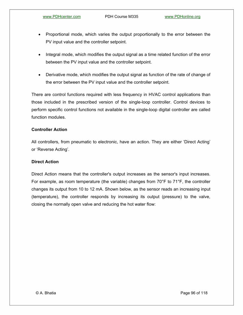
www.PDHcenter.com PDH Course M335 www.PDHonline.org
• Proportional mode, which varies the output proportionally to the error between the
PV input value and the controller setpoint.
• Integral mode, which modifies the output signal as a time related function of the error
between the PV input value and the controller setpoint.
• Derivative mode, which modifies the output signal as function of the rate of change of
the error between the PV input value and the controller setpoint.
There are control functions required with less frequency in HVAC control applications than
those included in the prescribed version of the single-loop controller. Control devices to
perform specific control functions not available in the single-loop digital controller are called
function modules.
Controller Action
All controllers, from pneumatic to electronic, have an action. They are either ‘Direct Acting’
or ‘Reverse Acting’.
Direct Action
© A. Bhatia Page 96 of 118
Direct Action means that the controller's output increases as the sensor's input increases.
For example, as room temperature (the variable) changes from 70°F to 71°F, the controller
changes its output from 10 to 12 mA. Shown below, as the sensor reads an increasing input
(temperature), the controller responds by increasing its output (pressure) to the valve,
closing the normally open valve and reducing the hot water flow:

www.PDHcenter.com PDH Course M335 www.PDHonline.org
Reverse Action
Reverse Action means that as the variable (for example, temperature) increases, the
controller's output decreases. For example, as room temperature rises from 70 to 71°F, the
controller output decreases from 8.1 to 7.3 mA. In the example below, as the sensor reads
an increasing temperature, the controller responds by decreasing its output (pressure) to the
valve, closing the normally closed valve and reducing the amount of heating. This
relationship is displayed on a graph as follows:
© A. Bhatia Page 97 of 118

www.PDHcenter.com PDH Course M335 www.PDHonline.org
The action of the controller must match the proper HVAC application. Normally open heating
valves always use direct acting controllers. If a reverse acting controller were to be placed
on a normally open heating valve, the heating valve would open as temperature rises. A
reverse acting controller never properly controls a normally open heating valve.
Identifying Reverse or Direct Action
Identification of a controller action for different applications could be determined from the
table below.
To use the table, follow the steps below:
1. First pick the correct application: for temperature, select heating or cooling; for humidity,
select humidification or dehumidification; for pressure, select whether the sensor is
downstream or upstream from the controlled device.
2. The second step is to determine how the application fails. Example, does the heat fail to
full ON or full OFF?
3. Third, once these questions are answered, follow the column down and follow the row
across to the intersection to find the correct action for that application.
© A. Bhatia Page 98 of 118
How to use the Table; follow the examples & steps below:

www.PDHcenter.com PDH Course M335 www.PDHonline.org
Example #1: Chilled water air-conditioning cooling application requires controlling a
normally open chilled water valve.
1. Under normal operation, the chilled water valve is open and as the temperature
decreases, the controller signals to close the normally open chilled water valve.
2. Since the valve is normally open, the “Fails to ON” row is used.
3. The column and the row intersect at Reverse Action. As the temperature increases, the
signal drops, allowing the chilled water valve to go to its normal open position. As the
temperature decreases, the signal increases, closing the normally open chilled water
valve.
Example # 2: A return air humidity sensor modulates a normally closed chilled water valve
for dehumidification. What action is needed for the controller?
Direct Action
Example #3: A static pressure sensor (located on discharge side) modulates normally
closed inlet vane dampers to maintain 2.0" w.c. (500 Pa). What action is needed for the
controller?
Reverse Action
Example #4: A room sensor cycles DX cooling to maintain a room temperature of 75°F .
The DX Cooling has normally open electrical contacts. What action is needed for the
controller?
Direct Action
Example #5: The mixed air sensor (located on discharge side) modulates the normally
closed outside air dampers and the normally open return air dampers to maintain a
temperature of 55°F. What action is needed for the controller?
Direct Action
© A. Bhatia Page 99 of 118
Transmitters

www.PDHcenter.com PDH Course M335 www.PDHonline.org
Variables such as temperature, pressure, and relative humidity are sensed by means of
elements that are connected to the control loops via transmitters. The transmitters are 2-
wire, loop-powered (i.e., powered by the control panel power supply) devices that connect in
a series circuit with the controller input.
The output signals of the transmitter is the standard 4 to 20 milliampere DC signal, which is
factory calibrated for zero point and span relative to the input resistance value of the sensing
element. The impedance limitation of the circuit in which the transmitter can function is
product specific. A typical value is 700 ohms at 24 volts dc.
Relays
Relays are used for control system interlocking functions and will be located in the system's
HVAC control panel. All relays, including time-delay relays, shall be 2-pole, double throw
devices.
Time Clocks
A time clock is used to control the timing of the modes of operation of an HVAC control
system when the control system is not interfaced with centralized energy management
control system (EMCS) or building management systems (BMS).
The modes of operation are occupied, unoccupied and ventilation delay. When used to time
the modes of operation of air handling systems, one contact of the clock will be used for
occupied and unoccupied timing; the second contact will be used for ventilation delay mode
timing. For other applications, the contacts may be used as convenient to the design.
CONTROL LOOPS
A control loop performs three distinct functions: sensing of a variable as the input to a
controller; decision making or control based on the value of the input; and output or
actuation as a result of control.
Figure below illustrates a simple control loop.
© A. Bhatia Page 100 of 118

www.PDHcenter.com PDH Course M335 www.PDHonline.org
The input signal is a continuous analog of the process, and the controller either continuously
sees the input or continually scans it. The controller changes its output as required by
changes in its input.
Open Control Loops
When a control loop senses a variable, makes a control decision, and sends an output
signal to a control device without receiving input information related to the results of its
control action, the control loop is said to be an open loop. It has no feedback i.e. there is no
way to monitor if the control system is working effectively. Open loop control is also called
feed forward control.
Some open-loop control applications used in HVAC control are:
• Operation of pumps above or below a certain outside temperature.
• Automatic stopping of HVAC systems based on outside air temperature.
• Scheduling of hydronic heating supply temperatures based on outside temperature.
• Timing and time-delay operations.
Figure below illustrates an open control loop.
© A. Bhatia Page 101 of 118

www.PDHcenter.com PDH Course M335 www.PDHonline.org
Open control loop
Closed Control Loops
When the controller changes its output decision based on updated input information, the
control loop is said to be a closed loop. In the closed system, controller responds to error in
controlled variable. A comparison of the sensed parameters is made with respect to the set
parameters and accordingly the corresponding signals shall be generated. Closed loop
control is also called feedback control.
Most of the control loops used in HVAC control are closed loops. Control of coil air
discharge temperatures is an example. The transmitter, connected to a temperature sensing
element in the air stream passing through the coil, signals the temperature controller; the
controller makes a decision as to whether to open or close the valve that allows water to
flow through the coil; and an actuator operates the valve. The feedback in this example is
the continuous input to the controller of a changing temperature signal from the coil air
discharge temperature sensor and transmitter.
The transmitter continuously updates the controller on temperature information from the
sensor, and the controller modifies its output to control the valve. See figure 2-9 for an
example of a closed control loop.
© A. Bhatia Page 102 of 118
Figure below illustrates a closed control loop.

www.PDHcenter.com PDH Course M335 www.PDHonline.org
Closed control loop
TYPICAL CONTROL MODES
Two-position control
Some HVAC equipment can be turned on and off as a method of temperature control. This
type of HVAC equipment is not applied where temperature control between close limits is
required.
© A. Bhatia Page 103 of 118
When a thermostat or other control device cycles equipment to maintain its setpoint the
control mode is called two-position control. A thermostat used for two-position control opens
and closes contacts for control rather than providing a modulating output signal. The
contacts either open or close when the temperature is at the thermostat setpoint. The state
of the contact reverses when the temperature changes in the proper direction. Such
thermostat contacts usually either open on a temperature rise (in a heating application), or
close on a temperature rise (in a cooling application). The temperature at which this
happens depends on the switch temperature differential (hysteresis).

www.PDHcenter.com PDH Course M335 www.PDHonline.org
An example of two-position control is unit heater control, in which a space thermostat turns
on a unit heater when the space temperature drops to 65° and turns it off when the space
temperature rises to 67°F. The thermostat is said to have a differential of 2°F and a setpoint
of 65°F. This type of control can result in a slight undershoot below the lower end of the
differential, and a slight overshoot above the higher end of the differential.
The output from the device is either on or off, with no middle state. A diagram of two-position
control as it relates to time and temperature is shown below.
Two Position On-Off Control Action
The response curve is always cycling between two limits ‘on’ and ‘off’ and overshoot and
undershoot occurs in practice because of variations in heat load due to the thermal inertia of
buildings and plant.
The difference between the temperatures at which the controller turns ‘on’ or ‘off’ is called
the ‘Differential’ or ‘Deadband’. If the deadband is large then control becomes ineffective.
Control or mechanical differential is difference between “on” and “off” values of controlled
variable.
© A. Bhatia Page 104 of 118
Operating or thermal differential is difference between extreme values (overshoot and
undershoot) of controlled variable, which in above example is the swing in the actual room
temperature.

www.PDHcenter.com PDH Course M335 www.PDHonline.org
The operational differential is wider than the control differential (Operating differential >
Control differential) because the actual room temperature always lags behind the equipment
turning ‘on’ or ‘off’.
Advantages
This is the simplest type of control action (and controller) and being relatively inexpensive is
used in many applications where it is acceptable to maintain the controlled variable within a
range. It is more suitable for plant having a slow reaction rate and high capacity on the
demand side e.g. 2-port or 3- port valve on the pipework to a hot water boiler.
Drawbacks
The drawback of this type of control is that it is relatively imprecise and inaccurate. It is
usually used where a precise control is not necessary, where the mass of the system is so
great that temperatures change extremely slowly. On/off control must be properly matched
to the system dynamics.
Modulating Control
© A. Bhatia Page 105 of 118
A simple control loop is shown in figure below as it would be applied to heat outside air for
ventilation using a pneumatic valve actuator rather than an electric or electronic valve
actuator.

www.PDHcenter.com PDH Course M335 www.PDHonline.org
Simple control loop applied to outside air heating
The controller operates an IP in response to the signal of the temperature sensing element
in the air duct, downstream of the coil, via a transmitter. The IP pneumatic output signal
modulates the positioner on the pneumatic valve actuator. The positive-positioner output
throttles main air to the actuator, which moves the valve stem. This example is used to
explain two modes of modulating control that are applicable to the control of valves,
dampers, inlet vanes, and other devices. The modes applicable to most HVAC control
applications are:
• Proportional mode (P)
• Proportional plus integral mode (PI)
PROPORTIONAL CONTROL MODE (P)
© A. Bhatia Page 106 of 118
With this form of control the valve or damper is positioned in intermediate positions in
proportion to the response to slight changes in the controlled condition. Therefore the
controlled device does not run through its complete stroke as in the case of two-position
control. Also the controlled device does not continue to move until it reaches a limit as in

www.PDHcenter.com PDH Course M335 www.PDHonline.org
floating control. Instead, with this form of control, the controlled device immediately assumes
a position in proportion to the system requirement. A linear relationship exists between the
input and the output. A setpoint, throttling range and action typically define this relationship.
This is finer control system than two-position system, and is designed to eliminate the
cycling associated with on-off control. It is typical in large HVAC systems.
Example: A modulating valve controls the amount of chilled water entering a coil so that
cool supply air is just sufficient to match the load at a desired setpoint. If the temperature is
further from the setpoint, the on- and off-times vary in proportion to the temperature
difference. If the temperature is below setpoint, the output will be “on longer”; if the
temperature is too high, the output will be “off longer.”
Proportional control maintains a setpoint with variations above and below that temperature.
A graph of proportional control used with room cooling is shown below.
Proportional Control Action
The figure, we can see that even though the setpoint is 74°F, the temperature doesn’t stay
constant. It rises and falls, wasting energy and mechanical cooling, and causing
uncomfortable temperature swings.
© A. Bhatia Page 107 of 118
Setpoint: Setpoint is the desired condition of a variable that is to be maintained, such as
temperature. The setpoint is an instruction to the control loop and corresponds to a specified
value of the controlled device, usually half travel. In figure above the setpoint is 74°F. A
room that needs relative humidity to be at 50% RH, or an air handler duct pressure that is to
be 2.0 inches of water column (500 Pa) is examples of setpoints.
www.PDHcenter.com PDH Course M335 www.PDHonline.org
Control Point: The value of the measured variable at any given moment is called the
control point. The control point is the actual temperature being sensed. The control point
(temperature) may not be on the setpoint, but instead may be above or below it. Systems
operate to maintain the setpoint, plus or minus some acceptable limits called differential
(two-position or on/off control) or throttling range (proportional control). Simply stated,
setpoint is what you want, while control point is what you get. In the example below, the
setpoint is 74°F (23°C), and the control point is at 73°F and varying.
Offset: Offset is the amount away from setpoint, or the difference between the setpoint and
the control point. In the example above, the offset is approximately 1°F.
Throttling Range: Throttling range (TR) is the change in the measured variable (i.e.
temperature) that causes the controlled device to travel from one end of its stroke to the
other. In the example above, it takes a TR of 4°F to cause the actuator to travel from the
completely open position to the completely closed position. Typical throttling ranges are 8°
to 10°F for mechanical controls such as mixed air control and the control of hot water
supply. In contrast, room controls must be much tighter, with a throttling range between 2°
and 4°F. Throttling range is sometimes referred to as insensitivity.
Smaller TR may cause stability problems. If the throttling range becomes too narrow, it
causes the actuator to go into a mode called hunting. In this mode, the actuator continually
searches (or hunting) for the proper controlled position full open, then full closed; then full
open, then full closed, etc. A control system that is hunting is not in control. It may be
possible to eliminate hunting by increase the throttling range so that the controller is less
sensitive.
Stability is tendency of a system to find a steady control point after an upset.
© A. Bhatia Page 108 of 118
Instability is tendency for oscillations to grow.

www.PDHcenter.com PDH Course M335 www.PDHonline.org
In proportional control, the control action is proportional to the deviation Q where Q is equal
to the difference between the setpoint and the measured value. When the measure value is
higher than the set value, the deviation Q will be positive and the correcting signal will be
negative and vice versa.
Mathematically this can be written as
Y = -kp Q
The problem with this type of control is that it will give rise to output offset i.e. constant error
between set value and the output value. One way to reduce offset is to reduce throttling
range. Reducing the throttling range too far will lead to instability. The more quickly the
sensor feels the control response, the larger the throttling range has to be to produce stable
control. Also the value of ‘should be’ kp chosen in such a way that it makes the system
response faster as well as it should not affect the stability of the system.
Facts about Proportional Control
1. The proportioning action occurs within a “proportional band” around the setpoint. Outside
this band, the controller functions as an on-off unit, with the output either fully on (below
the band) or fully off (above the band). At the setpoint (the midpoint of the proportional
band), the output “on: off” ratio is 1:1; that is, the ‘on-time’ and ‘off-time’ are equal.
© A. Bhatia Page 109 of 118
2. In proportional control, a unique value of the measured variable corresponds to full travel
of the controlled device and a unique value corresponds to zero travel on the controlled
device. The change in the measured variable that causes the controlled device to move
from fully closed to fully open is called the throttling range.

www.PDHcenter.com PDH Course M335 www.PDHonline.org
3. The type of action dictates the slope of the control response. In direct-acting proportional
control response, the output will rise with an increase in the measured variable. In a
reverse-acting response, the output will decrease as the measured variable increases.
4. Summarizing….
• Setpoint is desired value
• Control point is actual value
• Error or Offset = Setpoint - control point
PROPORTIONAL PLUS INTEGRAL MODE (PI)
Many control applications require a controller that can eliminate offset due to load and can
control very close to setpoint. The controller always tries to match the setpoint and every
time the load changes, the controller attempts to make the setpoint and the control point the
same. PI control measures offset or error over time. The error is integrated, and a final
adjustment is made to the output signal from a proportional part of this model. PI control
response will work the control loop to reduce the offset to zero.
Integral mode adds a gain component algebraically to the controller output. This component
is time proportional to the difference between the setpoint and the stable control point
produced by the controller's proportional gain. This difference is caused by the offset due to
load and is called steady-state error, which is the error between control point and setpoint
when a balance between the load on the system versus the system capacity output and
controller output is established. Steady-state error differs from the transitory error between
setpoint and control point due to an upset in the process, such as a changing load or a step
change in setpoint.
© A. Bhatia Page 110 of 118
The integral mode adds a component of output to the output of the controller that is
produced by the controller's proportional gain. The size of the component is determined by
the integral gain multiplied by the error. As the error decreases, the size of the component
integrated to the output signal also decreases, and becomes zero when the controller is
controlling at the setpoint. This added component of output causes the valve actuator stroke
position to change. The change in valve capacity resulting from the change in the actuator

www.PDHcenter.com PDH Course M335 www.PDHonline.org
stroke position upsets equilibrium or prevents equilibrium from occurring until the control
point reaches setpoint. This action causes two things to happen. The resulting temperature
change due to the change in valve actuator stroke position causes the proportional gain to
change its component of output signal at a magnitude proportional to the change in the
temperature being sensed. While this is happening, the error changes because the control
point is closer to setpoint, and this in turn causes the integral gain to make a change in the
magnitude of its component of the output signal due to the changing value of the magnitude
of the error between control point and setpoint. There will be no further change in the
proportional-mode or integral-mode output components when the steady-state error is zero.
Because of the combined action of both of these control modes, the controller can reduce
the offset to zero, or nearly zero, and can establish a steady-state equilibrium of HVAC
system control at a value very near setpoint. This type of control is called Proportional-
Integral (PI) control.
Example: This approach would be applied, for example, to space temperature control in
circumstances where the load fluctuated widely over relatively short periods of time. This
could not be achieved by proportional control alone since the proportional band would have
to be too wide. Also PI control is used more generally for applications where close control is
required.
Other examples of PI control in buildings include mixed-air control, duct static pressure
control, and coil controls. Assume that the room that is being controlled has an oversized
valve. While there is no substitute for a properly sized valve, Integral control can make this
condition less objectionable. To stop the actuator/valve assembly from hunting, a wide
throttling range 8°F (4°C) may be set.
However, room temperature swings of 8°F (4°C) are typically unacceptable and complaints
may become commonplace. A way to correct this situation may be to use proportional plus
integral, or PI control.
Advantages & Limitations
© A. Bhatia Page 111 of 118
The main advantage of this type of control is that the offset can be reduced.

www.PDHcenter.com PDH Course M335 www.PDHonline.org
A well set-up PI control loop will operate in a narrow band close to the setpoint and not over
the entire throttling range.
PI control loops do not perform well when setpoints are dynamic, sudden load changes
occur, or the throttling range is small.
DERIVATIVE CONTROL ACTION
Derivative control involves a further development of integral action such that the controller
output is a function of the rate of change of the controlled variable. This form of control, like
integral mode, would not normally be used alone, but in combination with others.
Effects of rapid load changes
The rate of change of load imposed on the HVAC system by the process affects how well
the controller will perform its task of controlling at setpoint. The temperature of the outside
air changes relatively slowly, and the temperature conditions inside also require some time
to change. Inside conditions change as a function of air temperature changes made by the
HVAC system, which warm up or cool down masses of material within the building. Inside
conditions also change as functions of lighting load and occupancy. Because of these
relatively slow rates of change, most of the HVAC processes that require gradual controller
output changes can be controlled quite well with proportional plus integral (PI) control
modes. Except for lighting loads on the HVAC system, these variable changes are relatively
slow compared to the rates of change of variables that affect some non-HVAC processes.
Lighting loads are sometimes imposed on the HVAC system quickly. This is an example of a
step change in the process variable. The combined actions of proportional and integral
modes are not always adequate to control rapidly changing variables.
PROPORTIONAL –INTEGRAL-DERIVATIVE (PID) CONTROL MODE
© A. Bhatia Page 112 of 118
Some processes require a controller that can respond to rapidly changing process variables.
One answer to control of rapidly changing processes has been the addition of another
control mode called derivative mode. When this control mode is added to proportional-
integral control, the combination is known as proportional-integral-derivative (PID) control
mode. The PID control mode adds a component algebraically to the output signal; this
component is proportional to the rate of change of the error between the control point and

www.PDHcenter.com PDH Course M335 www.PDHonline.org
setpoint. This automatic adjustment also affects the proportional and integral output
components in a manner analogous to the way in which the integral component affects the
proportional component. As the valve actuator stroke position changes, the temperature
changes as a result of changing flow through the valve, and the rate of error signal change
between the control point and setpoint varies as the control point comes closer to setpoint.
PID is a precision process control application and is recommended in systems where the
load changes often and the controller is expected to compensate automatically due to
frequent changes in setpoint, the amount of energy available, or the mass to be controlled.
Proportional-Integral-Derivative Control
PID control locks the control system to the setpoint, narrowing the HVAC system operating
range to just a few tenths of a degree, eliminating the widely varying temperature swings
experienced in proportional control, and maintaining the zone temperature within tenths of a
degree of the setpoint. As a result, the system uses the minimum amount of mechanical
cooling or heating to maintain zone temperature.
There are a few HVAC control applications that are difficult for either P-mode or PI-mode
control because of the fast rates of change of the process variables. One such application is
the control of tankless heating converters, such as might be found in some domestic hot
water heating applications. The ‘I-mode’ component of PI-mode takes care of the varying
range of offsets due to loads that occur in domestic hot water heating applications.
© A. Bhatia Page 113 of 118
For example, high-rise residential buildings have morning and evening peak periods of
demand for hot water use. These peak demand periods drive the domestic hot water
temperature to the low end of the offset range. Periods of relative non-occupancy, such as
late morning and early afternoon, drive the temperature to the high end of the offset range

www.PDHcenter.com PDH Course M335 www.PDHonline.org
due to the minimal demand for domestic hot water use. Periods of relative inactivity during
occupancy, such as late evening and very early morning, require practically no domestic hot
water. It is this period that defines the top end of the offset temperature range. The P-mode
control alone does not control the water temperature very close to the controller setpoint in
this kind of application. The addition of the ‘I mode’ to the ‘P mode’ makes the offset range
much narrower than would occur with P mode alone. However, PI modes alone cannot
handle the unpredictable diversity of demand as the peak periods start and end. What
happens during the period of light demand for hot water use is that the turn-on of a shower
or the startup of a dishwasher produces an upset in equilibrium that has a greater effect
than the same event would have during a period of heavy demand. Periods of heavy
demand tend to filter out some of the effect of a single turn-on.
In the control loop applications where manual tuning is prescribed, the proportional mode
constant is set as the result of a calculation. These applications cannot use the integral or
derivative control modes. Self tuning is prescribed for these applications because finding the
optimum setting manually is difficult and time consuming. When controllers self-tune, these
settings are automatically optimized, and an optimized derivative-mode setting is selected
due to the controller's self-tune feature.
In general, PID is not much suitable for HVAC applications firstly because the most HVAC
processes do not require rapid control response and secondly the operation is not very
energy efficient. Application rules dictate that for effective PID operation, valves and
dampers must be undersized so that a substantial pressure drop occurs across them under
all operating conditions. When applied to chilled- or heating water distribution systems, this
recommended valve pressure drop can as much as double the pumping power required.
This loss is magnified because PID control moves variable-speed pumps and fans away
from their "natural curves" (the curve of the pump's or fan's highest efficiency at various
speeds), thus reducing operating efficiency while adding substantially higher operating
pressure requirements.
STANDARD HVAC SYSTEM CONTROL LOOPS
© A. Bhatia Page 114 of 118
The standard HVAC system control loops use the single-loop digital controller and additional
components. These components are collectively called the control loop logic. The logic
varies with the loop requirements, and its purposes are to interface the loops with the

www.PDHcenter.com PDH Course M335 www.PDHonline.org
operational mode signals, to modify signals, and to interface with energy management
control systems (EMCS). The control loop logic is implemented by the use of combinations
of relays and function modules.
Relay coils are activated by occupied-unoccupied, ventilation-delay, safety shutdown,
EMCS override, and other signals external to the HVAC control system. The contacts of the
relays interrupt analog signals of controllers and function modules, provide inputs to on/off
control loops (such as starter circuits), and operate HVAC control panel pilot lights.
All the relays, contacts, and function modules are defined for each loop. The relative
physical locations of the relays and function modules will be assigned in the HVAC control
panels.
Each control loop on the drawings shall be represented to show the elements of the control
loop, such as sensor/transmitters, controller, function modules, relay contacts, current to
pneumatic signal converter (IP), and final actuator.
Stability of the System
Stability of a control system is concerned with its response to a disturbance. The system
must return to a steady state condition to be considered stable. An ‘Unstable’ system is
characterized by an oscillating response, or an ever increasing (or decreasing) response
until some natural limit is achieved.
An unstable system will often display a hunting behavior – the control valve is constantly
varying (In an HVAC system, the controlled device should not change more than 20% in a
10 minute period).
This produces excessive wear on the valves and actuators, produces thermal cycling that
may impact other equipment, structure, and contents of the building, or produce instabilities
in other parts of the system.
Factors contributing to an unstable system:
1. Too much gain (too narrow a throttling range) for a proportional system.
© A. Bhatia Page 115 of 118
2. The controlled variable has too much capacity to be reasonably controlled.

www.PDHcenter.com PDH Course M335 www.PDHonline.org
3. Lack of sufficient feedback to allow control (an open loop system).
4. Control mode is too simple (ON/OFF for example).
5. Incorrect install – Often, the sensor providing feedback is located in a remote location.
Several, tens, hundreds may be wired back to an I/O panel and several sensors may be
miss wired.
6. Too much lag time (delay) in the response of the system.
Oversizing of control devices would result in systems in which it would be difficult or
impossible to obtain satisfactory control loop operation, regardless of the quality of the
controller and components used.
The designer must not assume that self-tuning controllers will compensate for oversizing of
control devices.
The “I and D” modes compensate for HVAC system load variations and HVAC system
equilibrium upsets, but do not compensate for incorrect valve and damper sizing.
ENERGY MANAGEMENT OPPERTUNITIES
From the energy management perspective, the most important function is to optimize
control. The concept of optimizing control is not only to control space conditions, but also to
do it in a manner that minimizes the energy and costs when different forms of energy are
available. An optimizing strategy is generally to improve the efficiency of primary supply
equipment or to reduce the losses of energy in end-use systems.
Here are some of the critical control strategies that can save energy.
© A. Bhatia Page 116 of 118
1. Select realistic operating hours - For any building that shuts down overnight, every
extra hour per day of operation represents approximately 7% additional air-conditioning
energy. Don't run the building for a handful of early birds or night owls - generally
conditions in the building will be near enough to normal comfort levels without extended
hours.

www.PDHcenter.com PDH Course M335 www.PDHonline.org
2. Select realistic space conditions - Controls should be set up to provide a dead band
between 68oFand 73oF where neither heating nor cooling will occur. This band reduces
starting demands on plant and saves energy by recognizing that people dress differently
during heating and cooling seasons.
3. Logical zoning of HVAC areas - Zoning in a manner that areas of similar load
characteristics are controlled together can reduce energy use considerably by avoiding
the amount of re-heat needed to maintain conditions. In general, this is only possible at
the time of construction or major refurbishment. However, changing building use may
mean that sensors can be relocated to better reflect building conditions. In some cases,
relocation of partition can isolate sensors from the systems they control, under which
circumstances it is essential to relocate the sensor back into the relevant conditioned
space.
4. Early morning warm-up or cool-down - The strategy is to seal the building from the
introduction of outside air and apply maximum heating / cooling to achieve design
conditions in the minimum time. It is necessary to establish that the building will not be
occupied during this period and that the building has enough thermal storage to warrant
using the system.
5. Night time cool flush - This strategy uses "low heat" night air to cool the structure of
the building when the internal temperature is above the lowest comfort temperature. An
additional advantage is that internal air quality will be improved. When evaluating the
economics of this system, assess the power requirements of the fans required. It may be
no cheaper than using the chiller plant for a short period before occupancy; however this
technique does not improve air quality.
6. Fresh air control - When it is cooler outside than inside, it is often possible to use
outside air to provide cooling.
© A. Bhatia Page 117 of 118
7. Scheduling - Sophisticated control systems with 365 day clocks can be scheduled to
ensure that plant does not run on all days offices are not in use. Starting and stopping
times can also be changed when daylight saving commences and ceases. Continued
management is required to update the program for changes such as moveable feasts
and so on.

www.PDHcenter.com PDH Course M335 www.PDHonline.org
8. Optimum start/stop routines - These routines monitor the time taken for the building to
reach design conditions in the morning and to depart from design conditions when the
HVAC is shut off at night. The start and stop times are progressively modified over a
number of days until a good match with the building requirements is achieved. The
optimization routine continues to modify the start and stop times as the seasons change.
9. Improving Part Load Performance - The sizing of equipment is to meet maximum
loads, but the equipment is usually run at less than maximum load. This means that the
part -load characteristics of the equipment determines the efficiency in meeting a given
load. When there are multiple chillers or boilers, an optimizing strategy would be to
choose the most efficient equipment that has the capacity to meet the part load at any
given time.
While the modern day controls, have immense potential to capture data; it is useless unless
it can be associated with other date to provide some useful information. Don’t try to load
your control system too much. Remember, when it comes to control, it may be better to have
a building that is dumb and reliable than a building that is smart but scatterbrained. A simple
strategy to minimize risk in this respect is to keep the controls simple and robust rather than
complex.
© A. Bhatia Page 118 of 118
*******