hvac hygiene best practice guidelinehvac systems where they are required to facilitate the...
TRANSCRIPT

HVAC Hygiene Best Practice Guideline
A Guideline developed by the HVAC Hygiene Special Technical Group of AIRAH modified for New Zealand by IRHACE

IRHACE - HVAC Hygiene Best Practice Guideline Page 2
Preface
Specialised HVAC cleaning services have been available in New Zealand since the early 1980s. However, it was not until the 1990s that growing public concern for better indoor air quality (IAQ), improved indoor environment quality (IEQ) and improved ventilation hygiene that the cleaning of HVAC systems became a widely adopted practice. General awareness of occupational, public health and comfort issues associated with HVAC systems continues to increase and system owners and managers have responded with better management of these systems.
More recently, building energy use and energy conservation has become increasingly important to building owners and system operators, including the need to operate HVAC systems at their maximum efficiency. Maintaining HVAC systems in a clean condition is one essential and fundamental way of achieving these objectives.
Although Australian and New Zealand Standards, such as AS1851, AS/NZS 3666.2, and industry maintenance specifications, such as AIRAH DA19, specify requirements for HVAC system and component inspection and cleaning, very little criteria for evaluating and assessing different types and levels of contamination are provided.
This Guideline establishes the criteria for evaluating the internal cleanliness of HVAC system components and clearly determines when cleaning is required, according to the building use. The Guideline describes the components of HVAC systems to be evaluated, the types of contamination likely to be encountered and includes for post fire and flood damage assessments. Minimum inspection frequencies for various HVAC systems and components are specified for scheduled maintenance programs.
The Guideline also provides test methods that can be used to verify that a clean system hygiene level has been achieved following a system cleaning or restoration project.
This document also includes recommendations for creating new access openings within HVAC systems where they are required to facilitate the inspection and cleaning of the internal surfaces of system ductwork and components.
This Guideline does not provide instructions on how to clean or restore HVAC systems but does provide some guidance on the management of cleaning and restoration projects.

IRHACE - HVAC Hygiene Best Practice Guideline Page 3
Review and Revision
This Guide was published with the permission of AIRAH and was modified by IRHACE to suit New Zealand requirements.
To assist with the periodic review and revision of IRHACE Guidelines, users are encouraged to make known their experience in using this guideline and to notify IRHACE of any additional information which they can provide or to which reference can be made. This information should be forwarded to the IRHACE Centre.
Acknowledgements This edition of the Guideline was developed by the AIRAH HVAC Hygiene Special Technical Group and modified by IRHACE for New Zealand conditions and building code requirements. This was reviewed by Industry prior to publication.
We acknowledge AIRAH who allowed IRHACE the use of AIRAH HVAC Hygiene Best Practice Guideline and the original committee from AIRAH as listed below:
Jeremy Stamkos M.AIRAH
Vincent Borg M.AIRAH
Cedric Cheong
Michael Della Franca M.AIRAH
Brad George M.AIRAH
David Kearsley
Chris Luhrs M.AIRAH
Vincent Aherne M.AIRAH
Dr. Heike Neumeister-Kemp
Bruce Precious M.AIRAH
Bradley Prezant
Scott Summerville M.AIRAH
Stan Wesley L.AIRAH
Stephen Wilson
The assistance from these people is very much appreciated.
Some of the content of this Guideline, including the hygiene verification methods, has been based on the National Air Duct Cleaners Association (NADCA) USA industry standard ACR 2006 Assessment, Cleaning and Restoration of HVAC Systems and acknowledgement is given to NADCA for their permission to re-print this material.
We acknowledge the people who contributed to this edition of the Guideline as listed below:
Scott Summerville M.AIRAH
Robert Mannes MIRHACE
Editors Robert Mannes MIRHACE Michael Dane MIRHACE
Disclaimer The information or advice contained in this document is intended for use only by persons who have had adequate technical training in the field to which the Guideline relates. The document has been compiled as an aid only and the information or advice should be verified before it is put to use by any person. The user should also establish the applicability of the information or advice in relation to any specific circumstances. While the information or advice is believed to be correct, IRHACE Inc., its officers, employees and agents, disclaim responsibility for any inaccuracies contained within the document including those due to any negligence in the preparation and publication of the said document.
©IRHACE 2013
IRHACE - HVAC Hygiene Best Practice Guideline Page 4
IRHACE HVAC Hygiene Best Practice Guideline
Contents 1. HVAC Hygiene Management ........................................................................................... 7
1.1. Introduction ............................................................................................................... 7
1.2. Scope ....................................................................................................................... 8
1.3. Purpose .................................................................................................................... 9
1.4. Application ................................................................................................................ 9
1.5. HVAC System Classification .................................................................................... 9
1.5.1. General Use Systems .................................................................................... 10
1.5.2. Special Use Systems .................................................................................... 10
1.5.3. Kitchen Exhaust Systems ............................................................................ 10
1.5.4. NZBC New Zealand Building Code classification ...................................... 10
1.6. HVAC System Types and Components Defined .................................................... 11
1.6.1. Air Handling Unit ........................................................................................... 11
1.6.2. Supply Air - Moisture Producing Equipment .............................................. 11
1.6.3. Air Intakes and Exhaust Outlets .................................................................. 11
1.6.4. Supply Air System ......................................................................................... 11
1.6.5. Return Air System ......................................................................................... 12
1.6.6. Outside Air System ....................................................................................... 12
1.6.7. Exhaust Air System ....................................................................................... 12
1.6.8. Non-ducted Refrigerated Air Conditioners ................................................. 12
1.6.9. Evaporative Air Coolers ................................................................................ 12
1.6.10. Pre-Filtration .................................................................................................. 12
1.6.11. Post-Filtration ................................................................................................ 12
1.6.12. Representative Portion ................................................................................. 12
1.6.13. Terminal and Non-Terminal HEPA Filtration .............................................. 12
1.6.14. Containment Filtration .................................................................................. 13
1.6.15. Kitchen Exhaust Hood .................................................................................. 13
1.7. Contamination Types Defined ................................................................................ 13
1.7.1. General Dust and Particulates ..................................................................... 13
1.7.2. Biological Contamination ............................................................................. 13
1.7.3. Fungal Contamination .................................................................................. 14
1.7.4. Bacterial Contamination ............................................................................... 15
1.7.5. Viral Contamination ...................................................................................... 15
1.7.6. Asbestos ........................................................................................................ 15
1.7.7. Deteriorating Non-Porous Surfaces ............................................................ 16
IRHACE - HVAC Hygiene Best Practice Guideline Page 5
1.7.8. Deteriorating Porous Surfaces and Linings ............................................... 16
1.7.9. Water Damage ............................................................................................... 16
1.7.10. Fire and Smoke Damage ............................................................................... 16
1.7.11. Building or Renovation Contaminants ........................................................ 17
1.7.12. Odours ............................................................................................................ 17
1.7.13. Grease ............................................................................................................ 17
1.8. HVAC Hygiene Inspection Lifecycle ....................................................................... 17
1.8.1. Installation ..................................................................................................... 17
1.8.2. Commissioning ............................................................................................. 17
1.8.3. Scheduled Maintenance ............................................................................... 17
1.8.4. Unusual Contamination Event ..................................................................... 18
1.9. HVAC Restoration .................................................................................................. 18
1.10. Best Practice Hygiene Management ................................................................... 18
1.10.1. Principles ....................................................................................................... 18
1.10.2. Records .......................................................................................................... 18
1.11. HVAC Standards and Regulations ...................................................................... 19
2. System Inspection and Assessment .............................................................................. 20
2.1. Hygiene Levels Defined .......................................................................................... 20
2.2. Access for Inspection: HVAC Systems ................................................................... 20
2.3. Access for Inspection: Kitchen Exhaust Systems ................................................... 21
2.4. Inspection Frequency: HVAC Systems .................................................................. 22
2.5. Inspection Frequency: Kitchen Systems ................................................................ 23
2.6. Inspection Protocols ............................................................................................... 24
2.6.1. Systems and Components ........................................................................... 24
2.6.2. Contaminant Disruption ............................................................................... 25
2.6.3. Filters .............................................................................................................. 25
2.6.4. HVAC System Damage ................................................................................. 25
2.6.5. HVAC System Performance ......................................................................... 25
2.7. System Assessment ............................................................................................... 25
2.7.1. General Dust and Particulates ..................................................................... 25
2.7.2. Biological Contamination ............................................................................. 26
2.7.3. Fungal Contamination .................................................................................. 27
2.7.4. Asbestos ........................................................................................................ 27
2.7.5. Deterioration or Non-Porous Surfaces ........................................................ 28
2.7.6. Deterioration of Porous Surfaces and Linings ........................................... 28
2.7.7. Water Damage ............................................................................................... 28
2.7.8. Fire and Smoke Damage ............................................................................... 28
2.7.9. Building or Renovation Contamination ....................................................... 28

IRHACE - HVAC Hygiene Best Practice Guideline Page 6
2.7.10. Odours ............................................................................................................ 29
2.7.11. HVAC System Damage ................................................................................. 29
2.7.12. Hazardous Contaminants ............................................................................. 29
2.8. HVAC and Kitchen Hygiene Audit Report .............................................................. 29
3. System Cleaning and Verification .................................................................................. 30
3.1. Organising a Contract ............................................................................................. 30
3.1.1. The Cleaning Contract .................................................................................. 30
3.1.2. The Scope of Work ........................................................................................ 30
3.1.3. Additional Documentation ............................................................................ 31
3.2. Selection of Service Providers ................................................................................ 31
3.3. Health and Safety ................................................................................................... 31
3.4. Owner/Manager Responsibilities ............................................................................ 32
3.5. Containment Strategies .......................................................................................... 32
3.6. System Hygiene Verification ................................................................................... 33
3.6.1. Application ..................................................................................................... 33
3.6.2. Method 1 - Visual Inspection ........................................................................ 33
3.6.3. Method 2 - Surface Comparison Testing .................................................... 33
3.6.4. Method 3 - Vacuum Test ............................................................................... 34
3.6.5. Coil Cerification Test .................................................................................... 34
3.6.6. Fungal Decontamination Verification .......................................................... 34
3.7. Verification Reporting ............................................................................................. 35
3.8. HVAC Restoration Management ............................................................................ 35
4. Use of UV for Germicidal Irradiation .............................................................................. 36
4.1. Microbial Dose Response ....................................................................................... 36
4.2. Lamp Replacement ................................................................................................ 37
4.3. Personnel Safety Training ...................................................................................... 38
Appendix A Installation of Access Openings ................................................................... 39
Appendix B Vacuum Test Components and Method ...................................................... 41
Appendix C Notes on System Cleaning .......................................................................... 43
Appendix E Glossary of Terms ....................................................................................... 47
Appendix F Hygiene Level Reference Images ................................................................ 50
Appendix G Referenced Documents ............................................................................... 51

IRHACE - HVAC Hygiene Best Practice Guideline Page 7
1. HVAC Hygiene Management
1.1. Introduction Welcome to the IRHACE HVAC Hygiene Best Practice Guideline on why, how and when to maintain acceptable hygiene levels within heating, ventilation and air-conditioning (HVAC) systems.
Maintaining clean systems is an important part of sustainable HVAC system management. The benefits of maintaining HVAC systems in a clean state are considerable. Clean HVAC systems help to:
Improve indoor air quality as well as occupant health and wellbeing
Improve indoor environment quality and occupant productivity
Improve operational efficiencies
Reduce occupant dissatisfaction and complaints
Reduce system energy use, building running costs and associated carbon footprint
Reduce system maintenance requirements and system failure events
Reduce system fire hazards
Comply with statutory maintenance for safety and energy use
Increase system useful operating life
Improve overall building sustainability outcomes
Improve investment return from a building asset.
Overall, operating HVAC systems in a clean state reduces the building owners’ and system operators’ costs and exposure to risk.
Contaminants in HVAC systems can take many forms. Common contaminants include dusts and general particles, bacterial or fungal growth, debris from rusted HVAC components, man-made fibres, mould spores, pollens and moisture. Other contaminants can include asbestos, building debris, litter from animals, birds or insects and smoke residues.
Experience has shown that very few (if any) HVAC systems are free of all contaminants. In fact, particle deposition on component surfaces starts before the HVAC system is even installed. Airborne particles in factory settings and assembly areas are likely to settle on air-handling components and insulation or lining materials as well as adhere to the surface of metal components.
The installation process itself can subject the HVAC system to contamination. Construction sites contain a significant amount of airborne concrete dust, gypsum dust, sand particles, biological particulates, aerosols and many other airborne contaminants. These particles often settle on or within the HVAC system during the construction period. After the HVAC system has been installed, commissioned and its operation begins, the particulate accumulation process continues throughout the life of the system. Poor design, improper installation and commissioning practices, low-efficiency air filtration, excessive filter bypass, inadequate or infrequent preventative maintenance practices, humid conditions, and many other factors can result in contaminated HVAC systems. These HVAC systems may serve to transport and redistribute particles and contaminants from other sources in the building or may itself be the source of contamination. Considering HVAC hygiene throughout all stages (installation, commissioning and operation) of the system is essential to achieving optimum HVAC system outcomes.

IRHACE - HVAC Hygiene Best Practice Guideline Page 8
Aside from providing improved indoor air quality, better occupant comfort and more energy efficient systems, maintaining clean HVAC systems also helps to ensure that the responsibilities of any applicable OH&S legislation and due diligence to building occupants are being met and any building performance rating or environmental sustainability index rating is enhanced.
Unhygienic HVAC systems can lead to:
Increased risk to occupant health
Increased occupant complaints
Increased fire risks
Reduced system performance outcomes
Reduced productivity of occupants
Higher operating and future restoration costs
Increased risks to equipment and processes (data rooms, manufacturing)
Increased risk to building owners (loss of revenue, litigation).
Investing in HVAC system hygiene is not only an investment in the HVAC system but also an investment in the building and an investment in the wellbeing and productivity of the building occupants.
1.2. Scope This Guideline outlines protocols for inspecting the hygiene level of HVAC systems and components and includes assessment criteria for determining when cleaning or restoration is required. It defines what comprises various HVAC systems and components and defines the various types of contaminants that can be found within these systems. This Guideline also defines minimum acceptable system hygiene standards depending on the classification of the HVAC system and the building use.
In addition, this Guideline provides test methods that can be used to verify that a clean hygiene level has been achieved following the completion of a HVAC system or component cleaning or restoration project.
Furthermore this Guideline outlines the inspection and cleaning requirements for kitchen exhaust systems to ensure appropriate hygiene levels and fire risks are minimalised.
This Guideline also provides additional criteria for the creation and installation of new access openings used to facilitate the inspection and cleaning of HVAC systems and kitchen exhaust systems. Methods of surface sampling for the assessment of fungal contamination are also provided.
Figure 1.1 provides a map outlining the content of this Guideline.

IRHACE - HVAC Hygiene Best Practice Guideline Page 9
Figure 1.1 Map of HVAC Hygiene best practice guideline
Section 1 HVAC Hygiene
System Classification Contamination Type Inspection Best Practices
Section 2 Hygiene Levels
Hygiene levels System Access Inspection Protocols System Assessment Hygiene Report
Section 3 Manage Contract
Manage Contract Service Provider Manage Work Verification Methods Verification Report
Appendices Access Openings Vacuum Test Cleaning Procedures Surface Sampling Glossary
This Guideline does not include inspection or assessment recommendations for hazardous exhaust systems associated with laboratories or fume cupboards and the like. This Guideline does not specify recommendations for system cleaning methods however some guidelines on managing system cleaning projects are provided in Section 3.
1.3. Purpose It is the intent of this Guideline to provide building owners and managers, maintenance specifiers and providers, regulatory authorities, system designers, installers and commissioners, consumers, tenants, occupants and HVAC hygiene and indoor air quality industry professionals with a clear and defined outline of how to determine the internal hygiene condition of HVAC systems and when cleaning or restoration is required.
1.4. Application This Guideline can be applied to all heating, ventilation and air-conditioning (HVAC) systems including public and commercial applications. The recommendations of this Guideline apply to all classifications of buildings as outlined in the New Zealand Building Code (NZBC), except private residential buildings as specified herein. A glossary of HVAC hygiene terms is provided in Appendix E.
1.5. HVAC System Classification HVAC systems are classified on the basis of the type of enclosure that they serve and the associated population or process contained within it. Systems are classified into three categories; general use systems, special use systems, based on building use and kitchen exhaust systems. Each HVAC system within a building is classified separately depending on the enclosures it serves. If any part of a HVAC system serves a special use area then the entire system is classified as special use.

IRHACE - HVAC Hygiene Best Practice Guideline Page 10
Special use systems are generally associated with immuno-compromised populations (health or aged care), with food, pharmaceutical and electronics manufacture, and with other sensitive environments such as clean rooms and data centres. General use systems cover all other systems.
Kitchen exhaust systems are generally associated with restaurants, hotels, catering, and other food production facilities.
1.5.1. General Use Systems General use HVAC systems are systems serving buildings or enclosures (parts of buildings) used for general occupation and include public buildings such as schools, office spaces, libraries, court houses, cinemas, shopping centres, hotels, shops, restaurants and the like or any other buildings used for general occupation other than private residential buildings and those listed in 1.5.2.
General use systems also include systems serving any facility housing the manufacture, fabrication, processing, handling, and storage of materials or products not covered in 1.5.2
This classification also includes systems associated with ships or floating vessels with passenger facilities or crew cabins with the exception of those servicing special use areas as defined in 1.5.2.
1.5.2. Special Use Systems Special use HVAC systems are systems serving buildings or enclosures (parts of buildings) used as a hospital, out-patient care, doctor’s office, nursing home, aged care, extended care, or any other facility with a population comprising some individuals who may have compromised immune systems or where it is desirable to control particulate exposure for other reasons.
Special use systems also include any facility involved with the production of food products and pharmaceutical or electronics manufacturing.
Other special use systems may be systems associated with critical environments including clean rooms (any type), biological containment laboratories PC3, PC4 or other sensitive environments where higher than normal dust or other contaminant levels could cause an adverse effect on the activities, occupants or products in the enclosure, e.g. data or computer rooms.
1.5.3. Kitchen Exhaust Systems Kitchen hoods, grease filters, ducts, and exhaust fans become contaminated with grease as a by-product of the cooking process. This accumulation of flammable grease is the cause for many kitchen fires and poses potential fire risks to the facility where they are installed. Kitchen exhaust systems may be found in ships, hospitals, large food manufacturing facilities, hotels, shopping centres, restaurants and take away shops. This guideline does not extend to kitchen exhausts in a residential setting.
1.5.4. NZBC New Zealand Building Code Classification The relationship between the New Zealand Building Code (NZBC) building classification system and the hygiene Guideline HVAC system classification typically associated with that building use is provided in Table 1.1. Private residential buildings are excluded from the HVAC classification system.

IRHACE - HVAC Hygiene Best Practice Guideline Page 11
Table 1.1
NZBC and HVAC systems
New Zealand Building Code building type HVAC system classification
Residential houses and guest houses Not applicable
Residential units and apartments Not applicable
Hotel, hostel, care, prison General use
Sole occupancy unit Not applicable
Office building General use
Shop, restaurant, bar General use
Car park General use
Warehouse General or special use
Laboratory or manufacturing process Special use
Health care Special use
School assembly General use
Aged care Special use
Non-habitable Not applicable
1.6. HVAC System Types and Components Defined
1.6.1. Air Handling Unit The air-handling unit (AHU) means all components within the unit common to the system airflow including but not limited to filters and air bypass, heating and cooling coils, condensate pans and drain lines, humidification systems, internal insulation, fans and fan compartments, sensors, controls, dampers, plenums, chambers, access doors and door gaskets. This category includes fan coil units.
1.6.2. Supply Air - Moisture Producing Equipment Moisture producing equipment means cooling coils, humidifiers, air washers and the like installed remotely from the air-handling unit and including the lengths of ductwork immediately adjacent to such equipment. Excludes the air-handling unit and the rest of the supply air system.
1.6.3. Air Intakes and Exhaust Outlets Air intakes and exhaust outlets includes the louvre or grille, any filter or screen and the length of ductwork immediately adjacent to the intake or outlet.
1.6.4. Supply Air System The supply air system means the surfaces of supply air system components including, but not limited to, supply ducts, supply air plenums, sensors, controls, mixing VAV boxes, induction units, registers, diffusers and grilles, heating coils, electric duct mounted heaters, heat recovery devices and other internal components such as turning vanes, air dampers and noise attenuators. Excludes the air-handling unit and any moisture producing equipment.

IRHACE - HVAC Hygiene Best Practice Guideline Page 12
1.6.5. Return Air System The return air system means the surfaces of return air system components including, but not limited to return ducts, turning vanes, air dampers, return air plenums, heat recovery devices, sensors, controls, make-up air plenums and grilles.
1.6.6. Outside Air System The outside air system means the surfaces of the outside air system components including, but not limited to ducts, fans, sensors, controls, dampers, heat recovery devices, plenums and louvres and grilles.
1.6.7. Exhaust Air System The exhaust air system means the surfaces of the exhaust air system components including but not limited to ducts, dampers, fans, shrouds, sensors, controls, plenums and grilles. For the purposes of this Guideline the definition of exhaust air systems do not include kitchen exhaust systems (see AS 1851) or hazardous exhaust systems such as those associated with fume cupboards, laboratories and some manufacturing facilities.
1.6.8. Non-ducted Refrigerated Air Conditioners The non-ducted refrigerated air-conditioning unit (ceiling, wall, room, split and cassette types) means the various internal components of the unit including but not limited to, fans, coils, condensate trays and drains, louvres, internal insulation, filters and any sensors or controls. Ducted air-conditioning systems are treated as an AHU and supply air system.
1.6.9. Evaporative Air Coolers The evaporative air cooler means all components of the unit including but not limited to, sumps, wetted pads, water strainers, water recirculation pipe work, drainage system, fan, ducts, diffusers and any filters. Includes all air distribution system and components.
1.6.10. Pre-Filtration Pre-filtration, as referred in Table 2.4, means that part of the system exposed to unfiltered airflows prior to the installed system filters (if any).
1.6.11. Post-Filtration Post-filtration, as referred in Table 2.4, means that part of the system only exposed to filtered airflows downstream of the installed system filters (if any).
1.6.12. Representative Portion A representative portion of a supply, return or exhaust ductwork system is defined as the visual assessment of at least 5% of the internal surfaces of the system with inspected areas evenly distributed throughout the ductwork system.
1.6.13. Terminal and Non-Terminal HEPA Filtration HEPA filters will be located in HVAC systems serving special use facilities that require clean air conditions such as hospital operating theatres, clean rooms, biological containment facilities and others. The HEPA filters may be located within the air handling unit, supply air ducting or terminally mounted at leaving air point of the supply air ducting. Some will be located in exhaust ducts particularly in biological containment facilities and cytotoxic drug suites or isolation rooms.

IRHACE - HVAC Hygiene Best Practice Guideline Page 13
1.6.14. Containment Filtration Containment air filtration systems are high quality, high efficiency systems designed to capture dangerous toxic, or noxious airborne contaminants, both gaseous and particulate, and to contain them until disposed of properly. Safe change filtration housing is one example.
1.6.15. Kitchen Exhaust Hood Kitchen exhaust systems consist of the capture hood, grease filters, ducts, and exhaust fans that function to remove heat, smoke and grease laden air from the cooking process.
1.7. Contamination Types Defined Contaminants in HVAC systems may take many forms. Common contaminants include dust particles, bacterial or fungal growth, debris from rusted HVAC components, man-made fibres, mould spores, and other items. Gross contamination can arise from building debris, outdoor air contamination or pest ingress. Contamination can also arise from external events such as fire or smoke exposure, water damage due to floods or leaks or material generated by any system maintenance, building work or renovation activities. Potential asbestos contamination and contaminants generated from disintegrating or damaged internal insulation or lining products deserve particular consideration.
1.7.1. General Dust and Particulates This contaminant type includes all forms of general dust and particulates found in buildings including but not limited to dirt, spores, human hair and skin flakes, lint, pollens, fibres and the like.
Irrespective of the HVAC system design, construction materials, environment or filtration efficiency applied, some level of general dust and particulate matter will always infiltrate the components of the system. General dust and particulates are ubiquitous and can enter the system during the installation phase, during commissioning, during any renovations and simply through normal system use, particularly if system filters are bypassed or overloaded. Dust and particulates are often generated within the enclosure and enter the HVAC system with the return airstream. HVAC systems should be assessed for dust and particulate contamination in accordance with 2.5.1 of this Guideline.
1.7.2. Biological Contamination Biological contaminants include but are not limited to fungal contamination or colonisation, bacteria, viruses, parasites, insects, pollen, algae, amoeba, small animals, their faeces and any organic material deriving from the above such as decomposing carcasses or plant material. The differences between bacteria, viruses and fungi is that they all belong to different biological kingdoms, meaning they all have specific ways of living and reproducing and different cleaning practices and chemicals are used to deal with them. Generally viruses do not survive very well in air (or air-conditioning systems), bacteria and fungi can survive and even thrive. Bacteria will generally survive better in water (than in air), whilst fungi are well adapted to survive in both water and air.
The most common sources for biological contaminants in HVAC systems are the outdoor air and the return air. Others sources of biological contaminants result from water ingress, excessive moisture, excessive condensation or the infiltration of nutrients (dust) onto HVAC component surfaces. Whenever there is enough moisture and nutrients, biological contaminants can thrive. Biological contamination is assessed in accordance with 2.5.2 of this Guideline.
IRHACE - HVAC Hygiene Best Practice Guideline Page 14
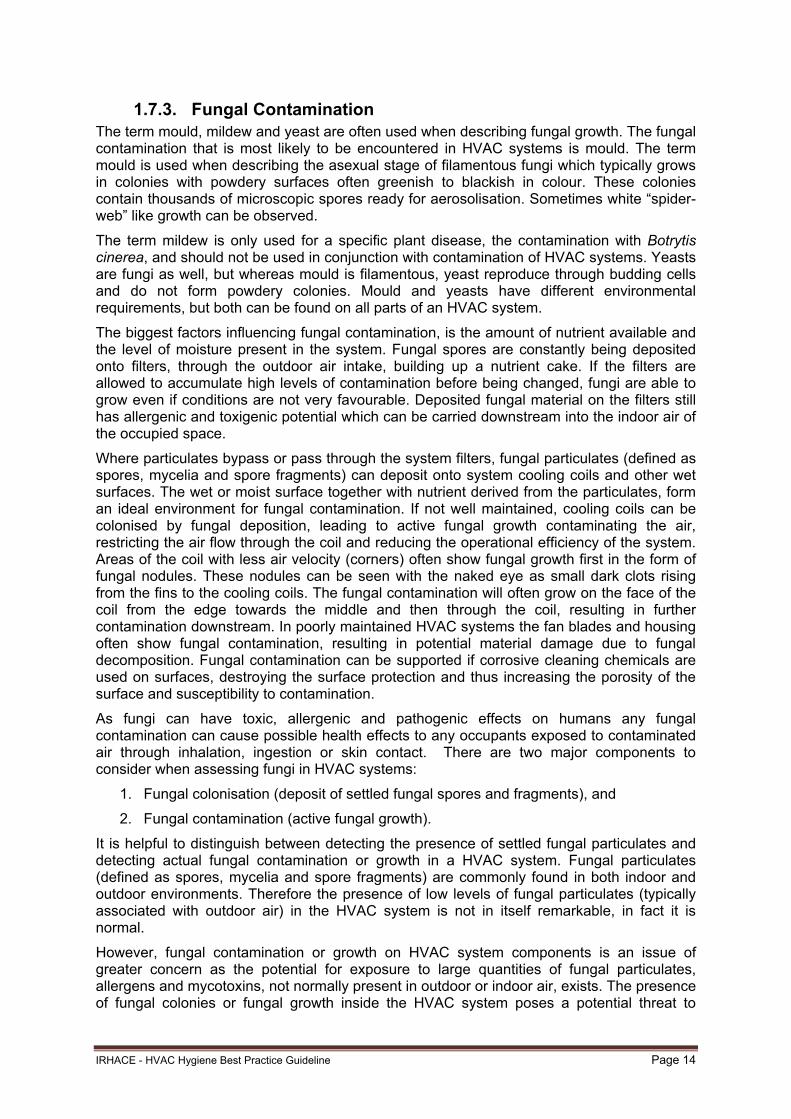
1.7.3. Fungal Contamination The term mould, mildew and yeast are often used when describing fungal growth. The fungal contamination that is most likely to be encountered in HVAC systems is mould. The term mould is used when describing the asexual stage of filamentous fungi which typically grows in colonies with powdery surfaces often greenish to blackish in colour. These colonies contain thousands of microscopic spores ready for aerosolisation. Sometimes white “spider-web” like growth can be observed.
The term mildew is only used for a specific plant disease, the contamination with Botrytis cinerea, and should not be used in conjunction with contamination of HVAC systems. Yeasts are fungi as well, but whereas mould is filamentous, yeast reproduce through budding cells and do not form powdery colonies. Mould and yeasts have different environmental requirements, but both can be found on all parts of an HVAC system.
The biggest factors influencing fungal contamination, is the amount of nutrient available and the level of moisture present in the system. Fungal spores are constantly being deposited onto filters, through the outdoor air intake, building up a nutrient cake. If the filters are allowed to accumulate high levels of contamination before being changed, fungi are able to grow even if conditions are not very favourable. Deposited fungal material on the filters still has allergenic and toxigenic potential which can be carried downstream into the indoor air of the occupied space.
Where particulates bypass or pass through the system filters, fungal particulates (defined as spores, mycelia and spore fragments) can deposit onto system cooling coils and other wet surfaces. The wet or moist surface together with nutrient derived from the particulates, form an ideal environment for fungal contamination. If not well maintained, cooling coils can be colonised by fungal deposition, leading to active fungal growth contaminating the air, restricting the air flow through the coil and reducing the operational efficiency of the system. Areas of the coil with less air velocity (corners) often show fungal growth first in the form of fungal nodules. These nodules can be seen with the naked eye as small dark clots rising from the fins to the cooling coils. The fungal contamination will often grow on the face of the coil from the edge towards the middle and then through the coil, resulting in further contamination downstream. In poorly maintained HVAC systems the fan blades and housing often show fungal contamination, resulting in potential material damage due to fungal decomposition. Fungal contamination can be supported if corrosive cleaning chemicals are used on surfaces, destroying the surface protection and thus increasing the porosity of the surface and susceptibility to contamination.
As fungi can have toxic, allergenic and pathogenic effects on humans any fungal contamination can cause possible health effects to any occupants exposed to contaminated air through inhalation, ingestion or skin contact. There are two major components to consider when assessing fungi in HVAC systems:
1. Fungal colonisation (deposit of settled fungal spores and fragments), and
2. Fungal contamination (active fungal growth).
It is helpful to distinguish between detecting the presence of settled fungal particulates and detecting actual fungal contamination or growth in a HVAC system. Fungal particulates (defined as spores, mycelia and spore fragments) are commonly found in both indoor and outdoor environments. Therefore the presence of low levels of fungal particulates (typically associated with outdoor air) in the HVAC system is not in itself remarkable, in fact it is normal.
However, fungal contamination or growth on HVAC system components is an issue of greater concern as the potential for exposure to large quantities of fungal particulates, allergens and mycotoxins, not normally present in outdoor or indoor air, exists. The presence of fungal colonies or fungal growth inside the HVAC system poses a potential threat to

IRHACE - HVAC Hygiene Best Practice Guideline Page 15
human health and is not considered acceptable hygiene practice for indoor environments. Fungal contamination should be assessed in accordance with 2.5.3 of this Guideline.
1.7.4. Bacterial Contamination Bacteria are microscopic unicellular organisms needing a moist environment. The main problem with bacteria in HVAC systems occurs when there is standing water. Blocked drain pipes or pans and biofilm formation on cooling coils and condensate pans are major sources of bacterial contamination. Airborne bacteria are generally transmitted to building occupants when they inhale aerosolised water or particulates. Legionella, Pseudomonas, Salmonella and Enterobacteria are all gram negative bacteria. Aerosolisation of Legionella from cooling towers can cause Legionnaires’ disease (see AS/NZS 3666.1). Bacterial contamination can be avoided by keeping all drains flowing and by not allowing standing water to form. Regular maintenance of cooling coils, pans and drains are necessary to remove the biofilms that may develop (see AS/NZS 3666.2).
1.7.5. Viral Contamination Viruses do not survive in air for a long time. Viruses need a host to survive and reproduce and are not considered as living organisms outside of their hosts. Viral contamination in HVAC systems is very rare, and often only occurs if a host parasite is present. Viral contamination in HVAC systems can best be avoided by keeping the system clean and free of any pests and parasites.
1.7.6. Asbestos Asbestos is a naturally occurring silicate mineral with long, thin fibrous crystals. Asbestos is a known carcinogen. The inhalation of asbestos fibres can cause serious illnesses, including malignant mesothelioma, lung cancer, and asbestosis (a type of pneumoconiosis). Since the mid-1980s, many uses of asbestos have been banned or discontinued in New Zealand. Asbestos became increasingly popular among manufacturers and builders in the latter part of the 20th century because of its resistance to heat, electricity and chemical damage, its sound absorption properties and its tensile strength. When asbestos was used for its resistance to fire or heat transfer, the fibres were often mixed with cement or woven into fabric or mats. Asbestos was used in and around electric duct heaters for its insulation properties at elevated temperature, and in building materials for its flame-retardant and thermal insulating properties, tensile strength, flexibility and resistance to chemicals. Asbestos gaskets were also commonly used in HVAC systems until their use was discontinued.
Particular attention to asbestos contamination in HVAC systems should be given to buildings that were constructed prior to 1980, the use of asbestos products in buildings constructed after this date is much less common. If the building has a ceiling void return air plenum that has or is likely to have had materials containing asbestos, or if the HVAC system contained materials likely to contain asbestos, then samples for traces of residual asbestos should be taken by competent persons in the return air ceiling voids and air ducts (refer to the New Zealand Guidelines for the Management and Removal of Asbestos 3rd Edition (http://www.osh.dol.govt.nz/publications/booklets/asbestos-management-removal/guidelines-25.asp).
The insulation surrounding electric duct heaters installed prior to 1980 may also contain asbestos fibres and should be considered to be so until it is verified otherwise by analytical assessment. Asbestos contamination should be assessed in accordance with 2.5.4 of this Guideline.
Asbestos is governed by the Health and Safety in Employment (Asbestos) Regulations 1998.

IRHACE - HVAC Hygiene Best Practice Guideline Page 16
The Health and Safety in Employment (Asbestos) Regulations (1998) regulate working with asbestos. They define ‘restricted work’ where OSH must be notified before the work begins and that the work must be carried out by a person holding a certificate of competence or by someone under direct supervision of a person holding a certificate.
(http://www.legislation.govt.nz/regulation/public/1998/0443/latest/DLM269298.html)
1.7.7. Deteriorating Non-Porous Surfaces Non-porous surface deterioration in an HVAC system includes corrosion of metal surfaces such as on fans, motor supports, filter frames, heating or cooling coils, condensate pans, dampers and galvanised metal ductwork. Deteriorating surfaces can impart particulates and odours to the airstream and create an ideal surface for microbial contamination.
1.7.8. Deteriorating Porous Surfaces and Linings Over time, internal fibreglass insulation within ducts and air handling units can deteriorate or be damaged through accessing, servicing and other indirect means. Moisture, fungal contamination, rodents, air erosion and inappropriate cleaning or maintenance activities can all lead to deterioration of the insulation or protective surfaces.
Untreated, damaged or deteriorated fibreglass insulation exposed to the system airflow can release fibreglass particles and fibres into the airstream contaminating the downstream components and the occupied areas served by the system.
Particular attention should be paid to fibreglass insulation materials that do not have any form of protective lining or coating such as compressed duct board, especially when it is located in the post filtration portion of the system.
Open and closed cell foam products have also been used as insulation material for HVAC systems for some time. Many of the older foam products may be prone to deterioration. As with other insulation products, deteriorated and detached internal foam insulation can be distributed through the system and eventually be delivered into the occupied areas that the system serves.
1.7.9. Water Damage Water damage can result from floods, heavy rain, water leaks, overflowing condensate pans and even fire suppression systems and activities. Water damage can also result from the water developed by condensation that occurs as a result of low (below dew point) surface temperatures in HVAC systems, particularly in high outdoor ambient temperature and relative humidity environments.
Water has the potential to rapidly deteriorate the porous and non-porous internal surfaces of HVAC systems and components. Fungal contamination, galvanic corrosion and degradation and deterioration of insulation materials can all occur or accelerate due to water damage.
All HVAC system surfaces and components subjected to water damage should be evaluated in accordance with 2.5.7 of this Guideline.
1.7.10. Fire and Smoke Damage When a fire occurs in a building the HVAC systems can act as a conduit for heat and smoke and can distribute contaminants throughout a system whether it was running during the fire or not. Smoke can contaminate internal surfaces and cause odours. The heat from fire and smoke can compromise system or component integrity and soot residues can accelerate fungal contamination especially in high carbon dioxide concentrations.
Many types of smoke residue can be highly corrosive to metal surfaces within the systems and smoke residues can also be toxic substances.
IRHACE - HVAC Hygiene Best Practice Guideline Page 17
All HVAC system components subjected to heat or smoke should be evaluated in accordance with 2.5.8 of this Guideline.
1.7.11. Building or Renovation Contaminants Any building, maintenance or renovation work has the potential to contaminate the HVAC system with dusts, chemicals and biological contaminants, particularly where the system is allowed to continue to operate and is not isolated during the work. Any HVAC system subject to this type of contamination should be evaluated to determine the hygiene level.
1.7.12. Odours Odours can be generated by introduced contaminants or by component degradation. Odours can be difficult to define and assess objectively and any odour contamination should be brought to the attention of the building owner.
1.7.13. Grease Grease is generated as a by-product of the cooking process. Kitchen exhaust systems should be evaluated for signs of grease accumulation that may lead to a fire, poor performance or hygiene that may have human health issues by attracting vermin.
1.8. HVAC Hygiene Inspection Lifecycle HVAC systems need to be inspected for hygiene levels throughout the system lifecycle including during system installation, commissioning and scheduled maintenance. Systems also need to be inspected after any unusual contamination event, such as flood or fire damage. Any systems that cannot be cleaned should be restored. Any components that cannot be restored should be replaced.
1.8.1. Installation HVAC system components should be inspected and verified as clean at the time of their manufacture, dispatch to site and when they are installed within the building.
Once installed in the building, clean components and system parts and sections should be protected from the ingress of contaminants where possible.
1.8.2. Commissioning Commissioning occurs when the system construction and installation has been completed and prior to handover of the building or system. Prior to system commissioning, all system components should be inspected and any contamination cleaned. The minimum acceptable hygiene level for all new systems at the pre-commissioning inspection should be clean in accordance with Table 2.1. Contaminated HVAC systems cannot be effectively commissioned. Commissioning is to be carried out to the requirements of CIBSE Commissioning Code A – Air systems.
1.8.3. Scheduled Maintenance HVAC systems and components should be regularly inspected and assessed in accordance with Section 2 of this Guideline and AS/NZS3666.2 as part of the system/building scheduled maintenance program. Where the minimum acceptable hygiene levels of this Guideline are not met, the system should be cleaned or restored.
Note: Scheduled HVAC hygiene inspection and assessment does not override any essential services maintenance requirements that apply and may need to be carried out in conjunction with it.

IRHACE - HVAC Hygiene Best Practice Guideline Page 18
1.8.4. Unusual Contamination Event HVAC systems and components should be inspected after any unusual contamination event such as a fire or flood or any renovation/building activities. Unusual contamination events are assessed in accordance with 2.5 of this Guideline.
1.9. HVAC Restoration Where HVAC systems or components cannot be adequately cleaned they should be repaired or replaced.
1.10. Best Practice Hygiene Management
1.10.1. Principles Best practice HVAC hygiene management can be achieved through the implementation of a few relatively simple management practices:
Filter Maintenance – Filters are the primary defence against dust and particulates. System filters should be regularly inspected and maintained, at least in accordance with the requirements of AS/NZS 3666.2 and AIRAH DA19 Application Manual – HVAC&R Maintenance. The initial system assessment should include a review of the filter specifications to determine if filter application is optimal for the HVAC system, including the filter type, filter rating, system airflow and pressure, the likely contaminant profile and the general quality of installation and maintenance. Filters shall comply with the minimum requirements of AS1668:2
Moisture Management – This is critical for minimising the potential for fungal contamination and any spills, leaks or wetting of HVAC systems or components should be dried out and inspected as soon as is practicable
Inspection and Assessment – All HVAC systems should be periodically inspected and assessed in accordance with the recommendations of this Guideline
Hygiene Level Management – Once systems or components have been identified as contaminated, cleaning and restoration work should be undertaken immediately including verifying the cleanliness of the restored system
Good Housekeeping – HVAC hygiene also requires a common sense approach to limiting contaminant generating activities within a building and promptly responding to any unusual contamination event. Even everyday tasks such as cleaning (vacuuming, disinfecting), food preparation and document printing and copying may be inadvertently introducing unacceptable contaminants into the HVAC system.
1.10.2. Records Best practice HVAC hygiene management requires good building and system documentation including up to date operation and maintenance manuals, accurate installed system drawings showing access points and original system commissioning data.
The building owner should maintain records of any conducted HVAC Hygiene Inspection Reports along with records of any cleaning or remedial works and any system hygiene verification carried out as a result of such inspections. Maintaining these records builds up a hygiene profile of a building or system over time that assists in HVAC hygiene management.
In addition, any reports relating to indoor air quality assessments or any energy management reports should also be retained with these records.

IRHACE - HVAC Hygiene Best Practice Guideline Page 19
1.11. HVAC Standards and Regulations The primary design standards for HVAC systems are listed in the New Zealand Building Code Section G4 which lists NZS4303 and AS 1668.2 which deals with ventilation requirements (minimum outdoor air, location of intakes and discharges, exhaust rates) and AS/NZS 3666.1 which deals with microbial control.
AS/NZS 1668.1 details requirements for fire and smoke control associated with mechanical ventilation systems.
The primary standard for HVAC systems operation and maintenance is AS/NZS 3666.2. Its primary focus is the control of microbiological contaminants such as Legionella sp. in building water and air handling systems but it also focuses on general HVAC hygiene.
The standard that covers the maintenance of the fire and smoke control features of HVAC systems is AS 1851.
AS/NZS 1668.1, NZS4303, AS 1668.2 and AS/NZS 3666 Part 1 and Part 2 are called up in the New Zealand Building Code as primary referenced standards and are mandatory in New Zealand. Apart from building legislation there may be specific occupational health and safety legislation and regulations relating to HVAC hygiene that should be complied with as they are relevant to both operation and maintenance.
The selection and application of general filters are covered by AS 1324 and minimum application requirements for the filtration of ventilation systems are specified in AS 1668.2. HEPA filters are classified in AS 4260.
It is not intended that the recommendations of this Guideline conflict with the requirements of any of these mandatory standards or with Government Regulations, Occupational Health and Safety requirements and the Workplace Exposure Standards and Biological Exposure Indices (http://www.osh.dol.govt.nz/order/catalogue/329.shtml)

IRHACE - HVAC Hygiene Best Practice Guideline Page 20
2. System Inspection and Assessment
2.1. Hygiene Levels Defined The descriptions listed in Table 2.1 provide the HVAC and kitchen system hygiene inspector with four hygiene levels to determine if cleaning is required when assessed against the minimum acceptable hygiene standards as listed in Table 2.4.
Table 2.1
Definition of Hygiene Levels
Hygiene Level Description
1. Clean HVAC: No visible dust, debris or other contamination
Kitchen: No visible grease accumulation
2. Light HVAC: Only slightly visible layer of fine general dust consistent over the component surface with little to no variations in density
Component surface remains visible beneath the fine layer of dust
Kitchen: Only slightly visible layer or film of grease consistent over the component surface with little to no variations in density
Component surface remains visible beneath the film of grease
3. Moderate HVAC: Visible levels of general dust with varying density and limited areas of accumulated fine debris
Component surface is still visible in some areas beneath the fine dust but in isolated sections may not be
Kitchen: Visible levels of grease with varying density and limited areas of accumulated and pooling grease
Component surface is still visible in some areas beneath the grease but in isolated sections may not be
4. Heavy HVAC: High levels of visible dust, debris, fibres or any other contamination that cover the component
Component surface is barely if not at all visible beneath the contamination
Kitchen: High levels of grease accumulation and pooling of grease contamination that covers the component
Component surface is barely if not at all visible beneath the grease contamination
Reference images for the four defined hygiene levels are provided in Appendix F.
2.2. Access for Inspection: HVAC Systems Access is required in order to inspect the internal surfaces of all components and a representative portion of the internal surfaces of the HVAC systems as defined in 1.6.12. AS/NZS 3666 Parts 1 and 2 both require adequate provision of access for maintenance.

IRHACE - HVAC Hygiene Best Practice Guideline Page 21
Inspections and assessments are visual and are generally carried out directly but can also be carried out remotely using robotic or manually operated camera systems. At the design and construction stages regard should be given to all requirements of space, position, access and repair (or replacement) in order to commission and maintain the equipment in an efficient operating condition, without undue difficulty, when using normally accepted maintenance procedures. As per section H1.3.6 (b) of the New Zealand Building Code: Where possible, access to HVAC system interiors should be made through existing openings such as supply diffusers, return grilles and existing duct access openings.
The most common locations for access openings in air ducts include adjacent to:
Dampers (balancing, fire and smoke, air control, back draft, splitter, etc.)
Duct mounted electric heaters
Heating, reheating and cooling coils
Mixing and VAV boxes
Other in-duct mechanical components & sensors.
Turning vanes.
Duct transitions, offsets, and changes of direction.
If new access openings are required to be installed to facilitate inspection or cleaning, they should be located near these system components. Each of these locations may require one or more access openings to properly access the ducts for inspection or cleaning. General recommendations for the installation of new access openings in ductwork systems are provided in Appendix A.
If new access openings are installed in the HVAC system their locations should be indicated on the updated “as installed” system drawings if available. System operating and maintenance information should also be updated.
2.3. Access for Inspection: Kitchen Exhaust Systems Access is required in order to inspect the internal surfaces of all kitchen ducts, components and equipment. Australian Standard AS 1851-2005 - Maintenance of Fire Protection Systems and Equipment. Section 18.4.1.11 Kitchen Exhaust Systems below sets out the minimum requirements of the standard – the requirements for the provision of access panel locations are listed below.
The most common locations for access openings in kitchen exhaust ducts include adjacent to:
Dampers (balancing, air control, backdraft, splitter, etc.)
Duct mounted sprinkler systems
Other in-duct mechanical components & sensors
Turning vanes.
Duct transitions, offsets, and changes of direction
Fans.
If new access openings are required to be installed to facilitate inspection or cleaning, they should be located near these system components. Each of these locations may require one or more access openings to properly access the ducts for inspection or cleaning. General
IRHACE - HVAC Hygiene Best Practice Guideline Page 22
recommendations for the installation of new access openings in ductwork systems are provided in Appendix A.
If new access openings are installed in the system their locations should be indicated on the updated “as installed” system drawings if available. System operating and maintenance information should also be updated.
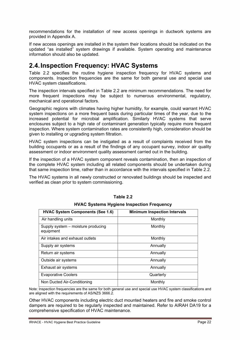
2.4. Inspection Frequency: HVAC Systems Table 2.2 specifies the routine hygiene inspection frequency for HVAC systems and components. Inspection frequencies are the same for both general use and special use HVAC system classifications.
The inspection intervals specified in Table 2.2 are minimum recommendations. The need for more frequent inspections may be subject to numerous environmental, regulatory, mechanical and operational factors.
Geographic regions with climates having higher humidity, for example, could warrant HVAC system inspections on a more frequent basis during particular times of the year, due to the increased potential for microbial amplification. Similarly HVAC systems that serve enclosures subject to a high rate of contaminant generation typically require more frequent inspection. Where system contamination rates are consistently high, consideration should be given to installing or upgrading system filtration.
HVAC system inspections can be instigated as a result of complaints received from the building occupants or as a result of the findings of any occupant survey, indoor air quality assessment or indoor environment quality assessment carried out in the building.
If the inspection of a HVAC system component reveals contamination, then an inspection of the complete HVAC system including all related components should be undertaken during that same inspection time, rather than in accordance with the intervals specified in Table 2.2.
The HVAC systems in all newly constructed or renovated buildings should be inspected and verified as clean prior to system commissioning.
Table 2.2
HVAC Systems Hygiene Inspection Frequency
HVAC System Components (See 1.6) Minimum Inspection Intervals
Air handling units Monthly
Supply system – moisture producing equipment
Monthly
Air intakes and exhaust outlets Monthly
Supply air systems Annually
Return air systems Annually
Outside air systems Annually
Exhaust air systems Annually
Evaporative Coolers Quarterly
Non Ducted Air-Conditioning Monthly
Note: Inspection frequencies are the same for both general use and special use HVAC system classifications and are aligned with the requirements of AS/NZS 3666.2.
Other HVAC components including electric duct mounted heaters and fire and smoke control dampers are required to be regularly inspected and maintained. Refer to AIRAH DA19 for a comprehensive specification of HVAC maintenance.

IRHACE - HVAC Hygiene Best Practice Guideline Page 23
2.5. Inspection Frequency: Kitchen Systems Table 2.3 specifies the routine inspection frequency for Kitchen exhaust systems and components.
The inspection intervals specified in Table 2.3 are minimum recommendations. The need for more frequent inspections may be subject to numerous environmental, regulatory, mechanical and operational factors such as the type of cooking process and the hours of operation of the kitchen exhaust.
How often should you clean your kitchen exhaust systems?
This depends on the volume of effluent produced from the cooking process and the hours of operation of your kitchen exhaust systems. Australian Standard AS 1668.2-2002 The use of ventilation and air-conditioning in buildings, Part 2: Ventilation design for indoor contaminant control recognises five types of cooking process:
Process Type 1 - Non-grease producing equipment and void spaces under the hood, which serve to ventilate other cooking equipment.
Process Type 2 - Low grease, medium heat producing equipment such as griddles,
ranges, convectional fryers, tilting skillets, steam kettles and gas ovens.
Process Type 3 – High grease, low heat producing equipment such as electric deep fat fryers, grooved griddles, hot tops and hot top ranges.
Process Type 4 - High grease, medium heat producing equipment such as
countertop barbeques and gas fired deep fat fryers.
Process Type 5 - High grease, high heat producing equipment such as woks, salamanders, and open flame charcoal equipment utilizing solid fuel.
The cleaning schedule will often depend on the cooking process type and generally speaking, Process Type 5 cooking would require the most regular cleaning.
Why clean kitchen exhaust hoods, associated ducting and exhaust fans?
Reduce the risk of fire starting from accumulations of flammable grease.
Where fire systems are installed they should be kept clean to ensure successful operation in the event of a fire,
To ensure the system operates to its design potential regarding airflow. Grease laden fans and ducting reduces the systems airflow and contributes to further grease build-up. Kitchens can become uncomfortably hot as the heat and the contaminants are not satisfactorily exhausted from ill performing systems.
The requirements that follow are those of Australian Standard AS 1851-2005 – Maintenance of Fire Protection Systems and Equipment - Section 18.4.1.11– “Kitchen Exhaust Systems’’. These are the minimum requirements of the standard.

IRHACE - HVAC Hygiene Best Practice Guideline Page 24
Table 2.3
Kitchen Systems Cleaning Frequency
Filters Check grease-arresting filters for excessive grease accumulation
Monthly
Hood and Plenum Check hood and its exhaust plenum for excessive grease accumulation
Monthly
Gutters Check grease gutters for excessive grease accumulation
Monthly
Filter (condition) Check that grease-arresting filters are secured in the correct position and undamaged
Monthly
Filter (clean) Clean grease-arresting filters as required Monthly Owing to wide variations in usage, frequency of cleaning is subject to the assessment of the inspector or the requirements of the regulatory authority. In some cases, cleaning may need to be more frequent than monthly
Hood and Plenum
Clean hood and its exhaust plenum
Annually
Filter (replace) Check for excessive leaks or damage to grease-arresting filters, and replace as necessary NOTE: Non-metallic grease filters and other special types have to be replaced at specific time intervals whether damaged or not. In these cases, follow manufacturer’s instructions
Annually
Duct Check duct for accumulated grease and clean
Annually
2.6. Inspection Protocols
2.6.1. Systems and Components The HVAC hygiene inspection should include all air handling units and representative areas of the related HVAC system components and ductwork as defined in 1.6.
The inspection of kitchen exhausts systems should be in accordance with table 2.3 above.

IRHACE - HVAC Hygiene Best Practice Guideline Page 25
2.6.2. Contaminant Disruption The hygiene inspection should be conducted without negatively impacting the indoor environment through excessive disruption of settled dust and debris or through microbial amplification. In cases where biological or fungal contamination is suspected, or in sensitive environments served by special use systems where even small amounts of contaminant may be of concern, environmental engineering control measures should be implemented, see Section 3.
2.6.3. Filters System filters should be assessed for:
Filter Classification – Confirm that the type and classification of the installed filter is consistent with the operating and maintenance documentation
Filter Air Bypass – Assess the filter frame, seals and housing for evidence of system air bypassing the filter
Filter Loading – Assess the contaminant loading of the filter, either visually or by pressure drop assessment and any sign of filter microbiological contamination
Filter Maintenance – Assess for evidence of a scheduled filter maintenance program.
2.6.4. HVAC System Damage HVAC components requiring repair due to pre-existing damage or degradation should be documented and brought to the attention of the building owner or representative and included in the HVAC hygiene inspection report.
Damage may include worn bearings, broken belts, lubricant leakage, rust and corrosion, damaged dampers, leaking coils or valves, leaking ductwork or access panels, damaged insulation, excessive noise or vibration and the like.
2.6.5. HVAC System Performance If the performance of a HVAC system is compromised due to contamination build-up, the affected system and or system components should be cleaned. If contamination within a HVAC system is found to be increasing energy consumption, reducing airflow, causing occupant ill health or discomfort, the affected system or components should be cleaned.
2.7. System Assessment During inspections, systems should be assessed against the following minimum HVAC hygiene criteria.
2.7.1. General Dust and Particulates Any system or components found to have accumulated general dust and particulate debris greater than the minimum acceptable hygiene standards as specified in Table 2.4 should be cleaned.
When the HVAC system or component is itself the source of contaminants that are being introduced into occupied spaces, system cleaning should be carried out to stop the contaminant introduction. The source of the contamination should be identified and rectified.

IRHACE - HVAC Hygiene Best Practice Guideline Page 26
Table 2.4
Minimum Acceptable System Hygiene Standards
HVAC System Classification (See 1.5)
HVAC & Kitchen sSystem or Component (See 1.6)
Minimum Hygiene Level (See Table 2.1)
General Use Systems AHU Clean
Supply system – moisture producing equipment
Clean
Air intakes and exhausts Clean
Supply air system, or
Return air system, or
Outside air system
Pre-filtration – Moderate
Post-filtration – Light
No Filtration – Light
Exhaust air system Moderate
Non-ducted refrigerated a/c Light
Evaporative coolers Light
Special Use Systems AHU Clean
Supply system – moisture producing equipment
Clean
Air intakes and exhausts Clean
Supply air system, or
Return air system, or
Outside air system
Pre-filtration – Light
Post-filtration – Clean
No Filtration – Clean
Exhaust air system Moderate
Non-ducted refrigerated a/c Clean
Evaporative coolers Clean
Kitchen Exhaust Systems
Filters Light
Hood and plenum Light
Gutters Light
Ducting Light
Fan Light
Note: Certain HVAC special use applications such as clean rooms, operating theatres and the like may have specific requirements for higher levels of HVAC hygiene determined by other governing bodies, manufacturing/processing activities, regulations and the like.
2.7.2. Biological Contamination The HVAC system and components should be visually assessed for biological contamination and any surfaces subject to biological contamination should be cleaned.
Particular attention should be given to outside air intakes, exhaust discharges and the methods of ingress of these contaminants. Air intake and discharge points should be screened to prevent the entry of pests, contaminants and moisture. Sources of biological contamination should be investigated and mitigated.
Coils, pans, sumps, drains and any wet surface in the HVAC system should be visually assessed for biological contamination. Components should be cleaned if any evidence of bacterial contamination or surface biofilm formation is present.

IRHACE - HVAC Hygiene Best Practice Guideline Page 27
2.7.3. Fungal Contamination The HVAC system and components should be visually assessed for fungal colonisation or fungal contamination on surfaces.
If fungal contamination in or on a system component is suspected, but not readily identifiable through visual assessment, then surface samples should be taken for laboratory analysis. Recommended procedures for taking surface samples for fungal contamination assessment are detailed in Appendix D.
If a system or component has been confirmed, by visual observation or analytical assessment, to be mould contaminated then the affected system or system components should be decontaminated. Decontamination or remediation of a mould affected system should only be undertaken if a thorough assessment of the system has been undertaken and not an assessment based on limited samples.
Note: Decontamination of a HVAC system due to mould or microbial contamination is a specialised activity that is outside the scope of this Guideline. State and Territory governments may have specific requirements for the reporting and control of microbial contamination within HVAC systems. System owners and operators should ensure that they are familiar with the regulatory requirements of the jurisdiction in which they operate.
Samples for fungal analysis need to be sent to a mycological laboratory for testing and assessment, and identification as a fungal growth site. Details of sample removal, transport, assessment and analysis should be coordinated with the testing laboratory.
Fungal species identification may be helpful to determine whether there is a shift from the indoor to the outdoor concentration. This is needed in order to perform a proper risk assessment. Clear communication between the building owner and the HVAC cleaner should be established in order to determine an acceptable fungal level following cleaning and remediation of the HVAC system.
Once the system has been decontaminated and cleaned the system hygiene level should be verified, see Section 3.
In particular the presence and source of moisture supporting any mould growth in the system should be identified and prevented.
Mould in buildings more generally is covered in the World Health Organisation (WHO) guidelines for indoor air quality, dampness and mould.
2.7.4. Asbestos If HVAC system contamination by asbestos dust or fibres is suspected then samples should be taken and analysed. If the presence of asbestos contamination is confirmed the entire system should be decontaminated by competent persons.
Note: Decontamination of a HVAC system due to asbestos contamination is a specialised activity that is outside the scope of this Guideline.
If potentially friable asbestos containing materials are found within a HVAC system, the system should be shut down, the asbestos containing material should be removed by licensed asbestos removalists and alternative insulation products installed in its place. This includes the insulation board surrounding duct mounted electric heaters if it is verified to contain asbestos.
Note: All asbestos removal work should be carried out in accordance with New Zealand Guidelines for the Management and Removal of Asbestos 3rd Edition and all other applicable state and local government regulations and requirements.
Once all asbestos materials and contamination have been removed the entire HVAC system should be cleaned and the system hygiene level should be verified. The components should be labelled as asbestos-free and the hazardous materials/asbestos register updated.
IRHACE - HVAC Hygiene Best Practice Guideline Page 28
2.7.5. Deterioration of Non-Porous Surfaces When the surface of non-porous components are deteriorated and contributing particulates or odours to the air stream, or otherwise adversely affect the quality of the air moving through the system, restoration should be performed and inspection/cleaning of all downstream components carried out as required.
2.7.6. Deterioration of Porous Surfaces and Linings When internal HVAC insulation or lining materials are found to be deteriorated and traces of the insulation or lining product found within the system components, the deteriorated surfaces should be restored and the affected components of the system should be cleaned and the entire system inspected for contaminants and cleaned as required.
2.7.7. Water Damage All HVAC system surfaces and components subjected to water damage should be evaluated to determine salvage ability and likely success of any restoration activity. In particular any internal insulation should be investigated for evidence of water logging or fungal growth.
Any system components or ducts deemed salvageable should be thoroughly cleaned and free from microbial growth. Any water affected or water logged insulation products should be replaced.
Any water damage due to condensation within the system also needs to be assessed and the cause of the condensation identified and mitigated.
Any water leaks (pipes, building structure) need to be identified and repaired prior to undertaking any HVAC cleaning or restoration work.
2.7.8. Fire and Smoke Damage All HVAC system components subjected to heat or smoke should be evaluated to determine their integrity and likely success of any restoration activity. In particular all fire and smoke dampers and all electric duct mounted heaters should be assessed for fitness for purpose in accordance with the survey and maintenance protocols of AS 1851.
Any components or surfaces deemed unable to withstand proper mechanical cleaning and restoration are beyond salvage and should be replaced. All porous surfaces subjected to fire or smoke damage should be evaluated for friability and odour retention following the cleaning process. Any areas assessed as friable should be replaced or resurfaced. Any materials likely to impart odours to the supply air stream should be replaced.
Any component surface exhibiting damage due to heat exposure should be restored to an acceptable condition or replaced. Consideration should be given to any residual smoke residue that may remain on the internal surfaces of the system. Certain types of smoke residue can be highly corrosive and lead to eventual deterioration of the affected component surface. Some smoke residues can also be toxic. Any metal surfaces affected by smoke, heat or smoke residue should be evaluated by competent persons to determine if restoration will be achievable or effective.
Any components affected by water from fire suppression activities should be assessed in accordance with 2.5.7.
2.7.9. Building or Renovation Contamination Any HVAC system subject to this contaminant category should be evaluated to determine the hygiene level of the system. Any system or components found to have accumulated general dust and particulate debris greater than the levels specified in Table 2.4 should be

IRHACE - HVAC Hygiene Best Practice Guideline Page 29
cleaned. Depending on the type of contamination encountered, certain irritant particulates may require cleaning at levels less than specified in Table 2.4.
2.7.10. Odours Odours are difficult to define and assess objectively and any odour contamination should be brought to the attention of the building owner.
If objectionable odours cannot be removed by system cleaning, the HVAC component(s) off-gassing the odour should be replaced.
2.7.11. HVAC System Damage Any system damage or degraded HVAC components should be assessed for their potential to contaminate the system or to allow contaminants to enter the system. Any HVAC system or component damage noted during the assessment should be documented and brought to the attention of the building owner or representative.
2.7.12. Hazardous Contaminants This Guideline excludes the inspection and assessment of any hazardous exhaust system (e.g. laboratories or processes). However where hazardous contaminants are encountered within a HVAC system they should be appropriately controlled and removed, see 3.5.
2.8. HVAC and Kitchen Hygiene Audit Report The findings of an HVAC or kitchen hygiene inspection and assessment should be reported in a clear and concise manner in an audit report. The HVAC and kitchen hygiene audit report should include at least the following information:
Name of client and contact details
Site address
Date of inspection
Name and qualifications of inspector
Date and identification of previous audit
Identification and type of system inspected
Any access limitations
System components inspected
Details of findings for each inspected component
Supporting digital images
List of which systems or components require cleaning as per this Guideline
List of which systems or components require restoration as per this Guideline
Other findings/recommendations
Any HVAC and kitchen system or component damage noted
Other system maintenance recommendations
Recommendations on duration to next audit and specific areas to be checked
A statement guaranteeing compliance of the audit with the recommendations of this Guideline.

IRHACE - HVAC Hygiene Best Practice Guideline Page 30
3. System Cleaning and Verification
3.1. Organising a Contract Once unacceptable HVAC kitchen exhaust system contamination has been identified, systems or system components need to be cleaned or restored. This is normally undertaken by a specialist service provider. The following information is provided to assist HVAC system and kitchen exhaust system managers organise and manage a cleaning contract.
Note: Additional notes on system cleaning procedures are provided in Appendix C.
3.1.1. The Cleaning Contract Any contract relating to a system cleaning project should include:
A description of the systems and components to be cleaned (See 1.6)
The scope of work (See 3.1.2)
The extent of any contractor guarantees
Dates, time periods and terms of payment
The responsibilities and limits of responsibilities of all parties
Insurance requirements
Details of any sub-contracts
Reporting and verification arrangements
Photos of specific areas to be treated
Site availability for cleaning (days and work hours).
3.1.2. The Scope of Work The scope of work should unambiguously define the services to be provided. The scope of work should make it clear whether any or all of the following services are required:
Installation of new access openings, doors and panels
Clean air handling units
Clean ductwork systems – supply, return, exhaust, outside air
Remove/clean/replace - filters, registers, grilles
Clean - plenums, heat exchangers, coils
Clean systems - non-ducted air-conditioners, evaporative air cooler
Visual verification inspections
Verification testing
Restoration, repair or replacement of HVAC components
Re-commissioning of cleaned systems, airflows, air balance, pressure drops, pressure differentials, air change rates and the like
Cleaning of all kitchen exhaust systems including hoods, gutters, ducting, filters and fans.

IRHACE - HVAC Hygiene Best Practice Guideline Page 31
3.1.3. Additional Documentation The contractor should provide documented information on:
Site specific project management plan including containment strategies
Cleaning methods – ductwork, coils, fans, pans and drains
MSDS of any chemicals to be used
Disposal and handling strategies for removed contaminants
Odour management
Noise control
Verification (of cleaning operations) protocol.
3.2. Selection of Service Providers The selection of a service provider is crucial to a satisfactory HVAC and kitchen exhaust system cleaning operation. A potential service provider should have the following attributes:
Compliance with the recommendations of this Guideline
Appropriate level of resources
Evidence of experience and training and a record of previous work
Appropriate insurances and licences
Informative reporting system
Quality, environmental and safety management systems.
3.3. Health and Safety Contractors should comply with all applicable legislated requirements for protecting the health and safety of their employees, building occupants, the general public and the environment.
The contractor should comply with all applicable regulations including but not limited to the following:
Working in confined spaces
Working at heights
Respiratory protection and personal protective equipment (PPE)
Hazard communication
Lock out / tag out isolations
Fall protection
Environmental controls (hazardous substances - HSNO Act 1996).
Maintenance personnel should be appropriately trained in first aid and any applicable emergency procedures.
Workplace hazards are not always obvious, they may be concealed or not be readily visible, they may develop over time and some hazards may be temporary or intermittent. Service personnel may not be familiar with the site or workplace which can present a further hazard.

IRHACE - HVAC Hygiene Best Practice Guideline Page 32
To properly identify and manage exposure to risk associated with hazards in the workplace the five step risk management process should be followed:
1. Identify hazards
2. Assess the risk
3. Decide on control measures
4. Put control measures in place
5. Review the control measures.
Control measures should be implemented in the following hierarchy:
1. Remove the hazard
2. Reduce the hazard
3. Separate the hazard from people
4. Engineering measures
5. Administrative measures
6. Personal protective equipment.
Access required shall comply with the requirements of the NZBC Acceptable Solution D1 Access Routes.
3.4. Owner/Manager Responsibilities It is useful to define a list of system manager’s responsibilities in addition to the provisions for payment and accepting reports. Manager responsibilities during the delivery of a HVAC cleaning project include;
Provision of appropriate access to the site
Provision of accurate system operation and maintenance information
Provision of “as installed” system construction drawings
Provision of power, water and drainage facilities for cleaning processes
Provision of supplemental heating, cooling or ventilation if required when systems are off line
Participation in cleaning verification protocols
Inform occupants and emphasise benefits of investment
Communicate between parties.
3.5. Containment Strategies Some form of containment strategy is required for every cleaning project. Containment strategies to be applied should be detailed in the service providers’ project management plan. The level and extent of containment strategies applied in any project will depend on:
The type, use and layout of the building
The size and complexity of the HVAC system
The type of contaminant involved
The use of the enclosure
The (likely) type of occupants

IRHACE - HVAC Hygiene Best Practice Guideline Page 33
Containment strategies can range from administrative measures to environmental engineering control measures and can include the use of signage, physical barriers, air pressure differentials and air filtration or cleaning devices.
A containment strategy would usually include the establishment of containment areas within the work area. Other issues that may need to be considered in the containment strategy are:
Contaminant collection and handling
Wash down protocols and facilities
Collection and treatment of any drainage
All vacuum and extraction units and exhaust fans used to create negative pressures should be equipped with HEPA filtration systems to prevent contaminant escape and recontamination occurring through secondary dispersal.
3.6. System Hygiene Verification
3.6.1. Application Verification of a HVAC and kitchen exhaust system cleaning process should be performed directly after the system or component has been cleaned and prior to the component being put back in to operation. All verification tests should be conducted prior to the application of any surface treatments of the component's surface. This post cleaning verification process applies to all porous and non-porous components within the HVAC and kitchen exhaust system.
Several methods of hygiene verification are described in this Guideline. Visual and analytical verification methods are provided. Not all methods can be applied to non-porous surfaces. Analytical methods do not apply to kitchen exhaust systems.
All methods are intended to assist in the verification that system surfaces are clean. The verification methods do not determine light or moderate hygiene levels. HVAC system hygiene verification is not designed to determine if an HVAC system needs to be cleaned. In order to determine if a HVAC system needs to be cleaned see Section 2 of this Guideline.
3.6.2. Method 1 - Visual Inspection A visual inspection of porous and non-porous HVAC system components should be used to assess that the HVAC and kitchen exhaust system is visibly clean. An interior surface is considered visibly clean when it is free from non-adhered substances and debris. If a component is visibly clean then no further hygiene verification methods are required.
If the visual inspection is inconclusive regarding acceptable contaminant reduction, then surface comparison testing should be performed on HVAC systems only.
3.6.3. Method 2 - Surface Comparison Testing This method does not apply to kitchen exhaust systems.
The Surface Comparison Test can be used to determine cleanliness of both porous and non-porous HVAC component surfaces. The component’s surface conditions are evaluated by comparing visible characteristics of the test surface before and after implementing a specific procedure of contact vacuuming.
The testing contact vacuum should be HEPA filtered and capable of achieving a minimum of 10kPa (40” water gauge). The contact vacuum should be fitted with a 60mm (2.5”) round nylon brush attached to a 37.5mm (1.5”) diameter vacuum hose.
The vacuum brush is attached to the contact vacuum and the device should be running. The brush should be passed over the surface test area four times, with the brush depressed

IRHACE - HVAC Hygiene Best Practice Guideline Page 34
against the surface being tested using light to moderate pressure (as used in routine cleaning).
When this procedure has been completed, a comparison should be made to determine if the visible characteristics of the surface have changed significantly. The HVAC component surface is considered to be clean when there is no significant visible difference in the surface characteristics.
If surface comparison testing is inconclusive, then the vacuum test procedure may be used to make a final cleanliness determination. The vacuum test can be used for non-porous system components surfaces only and does not apply to porous system component surfaces.
3.6.4. Method 3 - Vacuum Test This method does not apply to kitchen exhaust systems
The Vacuum Test is used for scientifically evaluating remaining particulate levels of cleaned, nonporous HVAC component surfaces.
Using this procedure (See Appendix B) a template is applied to the airside surface of the component to be tested. A vacuum cassette with filter media is attached to a calibrated air pump and the open face of the filter cassette is passed over two 2 cm x 25 cm openings within the template. At no time can any portion of the vacuum cassette directly contact the component surface being tested. The template is specifically designed to allow the cassette to ride above the surface being tested. Airflow is accelerated through a narrow opening between the template and the test surface of the component, allowing any latent remaining particulates from the component’s surface to be dislodged through increased air velocity and impinged onto the filter media within the vacuum cassette.
After the sampling procedure the filters are weighed to determine the amount of total particulates and debris collected on the filter media. To be considered clean by the Vacuum Test, the net weight of the debris collected on the filter media should not exceed 0.75mg/100 cm2. The equipment and test procedure are specified in Appendix B.
3.6.5. Coil Verification Test Cleaned coils should be visually clean when inspected in accordance with Method 1, and the coil resistance (air pressure drop) should be measured.
The pressure drop across the cleaned coil should be measured at normal operating conditions. Care should be taken to ensure all measurements are undertaken at 100% of supply air capacity. Variable speed drives may require manual override to establish full flow conditions.
The measured pressure drop across the coil should be as close as possible to the original design specification for the coil and never more than 20% greater than the original design specification.
3.6.6. Fungal Decontamination Verification Decontaminated systems and components should be visually clean when inspected in accordance with Method 1. If required, verification tests for fungal decontamination should follow the guidelines for fungal contamination assessment as outlined in 2.7.3. Verification test acceptance levels should be determined by agreement between the system owner or manager and service provider.
Fungal species identification may be helpful to determine whether there is a shift from the indoor to the outdoor concentration. Clear communication between the building owner and the HVAC system cleaner should be established in order to determine an acceptable fungal level following cleaning or decontamination of the HVAC system.

IRHACE - HVAC Hygiene Best Practice Guideline Page 35
3.7. Verification Reporting Any verification of an HVAC cleaning process should be detailed in a hygiene verification report. The Post Clean Hygiene Verification Report should include the following:
Name of client and contact details
Site address
Date of inspection
Name/qualification of inspector
Identification of system inspected
System components inspected
Identify which hygiene verification method was used
Details of findings for each inspected component
Supporting digital images verifying written findings
Any recommendations
Reference to this Guideline.
3.8. HVAC Restoration Management When system cleaning or decontamination is inappropriate or unsuccessful then systems will need to be restored. Restoration includes repair and replacement and may be carried out in conjunction with, after or instead of system cleaning. All new construction and installation work should comply with the relevant Australian/New Zealand Standards and the requirements of the New Zealand Building Code.
Systems or components that are restored should be re-commissioned so that the original system design requirements are achieved.
Commissioning shall be undertaken to the requirements of CIBSE Commissioning Code A.

IRHACE - HVAC Hygiene Best Practice Guideline Page 36
4. Use of UV for Germicidal Irradiation UV energy is electromagnetic radiation with a wavelength shorter than that of visible light, and therefore invisible to the human eye, but longer than soft x-rays. The UV spectrum can be subdivided into following bands:
• UV-A (long-wave; 400 to 315 nm): the most abundant in sunlight, responsible for skin tanning and wrinkles
• UV-B (medium-wave; 315 to 280 nm): primarily responsible for skin reddening and skin cancer
• UV-C (short-wave; 280 to 200 nm): the most effective wavelengths for germicidal control; Radiation <200 nm is also called vacuum UV and produces ozone (O3) in air.
4.1. Microbial Dose Response Lamp manufacturers have published design guidance documents for in-duct use (Philips lighting 1992; Sylvania 1982; Westinghouse 1982). Bahnfleth and Kowalski (2004) and Scheir and Fencl (1996) summarised the literature and discussed in-duct applications.
These and other recent papers were based on case studies and previously published performance data.
The data indicated that UV-C systems can be used to inactivate a substantial fraction of environmental bioaerosols in a single pass.
The most effective UV wavelength range for inactivation of micro-organisms was between 220 to 300 nm, with peak effectiveness near 265 nm.i
UV-C energy disrupts the DNA of a wide range of microorganisms, rendering them harmless. Shows the relative effectiveness of UV-C energy at various wavelengths to cause DNA damage.
Most, if not all, commercial UV-C lamps are low-pressure mercury lamps that emit UV energy at 253.7 nm, very close to the optimal wavelength.
Ultraviolet germicidal irradiation (UVGI) in the UV-C band has been used in air ducts for some time, and its use is becoming increasingly frequent as concern about indoor air quality increases. UVGI is being used as an engineering control to interrupt the transmission of pathogenic organisms, such as Mycobacterium tuberculosis (TB), influenza viruses, mold, and possible bioterrorism agentsii.
Organisms differ in their susceptibility to UV inactivation; Figure 1 shows the general ranking of susceptibility by organism groups. Viruses are a separate case because, as a group, their susceptibility to inactivation is even broader than bacteria or fungi. Note that it is impossible to list all of the organisms of interest in each group.
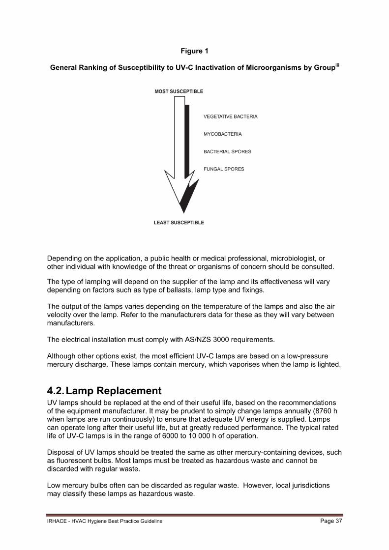
IRHACE - HVAC Hygiene Best Practice Guideline Page 37
Figure 1
General Ranking of Susceptibility to UV-C Inactivation of Microorganisms by Groupiii
Depending on the application, a public health or medical professional, microbiologist, or other individual with knowledge of the threat or organisms of concern should be consulted. The type of lamping will depend on the supplier of the lamp and its effectiveness will vary depending on factors such as type of ballasts, lamp type and fixings. The output of the lamps varies depending on the temperature of the lamps and also the air velocity over the lamp. Refer to the manufacturers data for these as they will vary between manufacturers. The electrical installation must comply with AS/NZS 3000 requirements. Although other options exist, the most efficient UV-C lamps are based on a low-pressure mercury discharge. These lamps contain mercury, which vaporises when the lamp is lighted.
4.2. Lamp Replacement UV lamps should be replaced at the end of their useful life, based on the recommendations of the equipment manufacturer. It may be prudent to simply change lamps annually (8760 h when lamps are run continuously) to ensure that adequate UV energy is supplied. Lamps can operate long after their useful life, but at greatly reduced performance. The typical rated life of UV-C lamps is in the range of 6000 to 10 000 h of operation. Disposal of UV lamps should be treated the same as other mercury-containing devices, such as fluorescent bulbs. Most lamps must be treated as hazardous waste and cannot be discarded with regular waste. Low mercury bulbs often can be discarded as regular waste. However, local jurisdictions may classify these lamps as hazardous waste.

IRHACE - HVAC Hygiene Best Practice Guideline Page 38
4.3. Personnel Safety Training Warning labels must be posted on all upper-air UV fixtures to alert personnel of potential eye and skin hazards. Workers should not expose themselves to UV radiation. Workers should be provided with as much training as necessary, including health and safety training, and some degree of training in handling lamps and materials. Workers should be made aware of hazards in the work area and trained in precautions to protect themselves including:
UV exposure hazards
Electrical safety
Lock-out/tag-out
Health hazards of mercury
Rotating machinery
Slippery condensate pans
Sharp unfinished edges
Confined-space entry (if applicable)
Emergency procedures
Workers expected to clean up broken lamps should be trained in proper protection, clean up, and disposal. No personnel should be subject to direct UV exposure, but if exposure is unavoidable, personnel should wear protective clothing (no exposed skin), protective eyewear, and gloves. Access to lamps should only be allowed when lamps are de-energised. The lamps should be turned off before air-handling unit (AHU) or fan shutdown to allow the lamps to cool and to purge any ozone in the lamp chamber (if ozone-producing lamps are used). If AHUs or fans are de-energised first, the lamp chamber should be opened and allowed to ventilate for several minutes. Workers should always wear protective eyewear and puncture-resistant gloves for protection in case a lamp breaks.

IRHACE - HVAC Hygiene Best Practice Guideline Page 39
Appendix A Installation of Access Openings
A1 Access Openings
Access openings are necessary in HVAC system components and ducts, to facilitate inspection, testing, adjustment and cleaning.
Where possible, access to HVAC system interiors should be made through existing openings such as supply diffusers, return grilles and existing access openings, panels and doors.
If new access openings are required to be installed, they should be located near system components, at changes in duct direction or size and either side of obstructions such as turning vanes, dampers, fans and the like. They should be suitably sized to allow sufficient access to undertake the inspection and cleaning work.
Poorly constructed access openings may have a negative impact on the HVAC system. An air duct system, when improperly altered, may compromise the system’s structural integrity and fire rating integrity. Poorly installed access openings can act as a site for duct air leakage or infiltration and may affect indoor air quality by serving as a conduit that can expose both the HVAC system and the indoor environment to contamination.
No matter the type of duct construction used, it is important that access openings be constructed in a manner that facilitates a proper closure. Contractors inexperienced in the physical creation of access openings are recommended to seek appropriate training prior to attempting this work.
A2 General Recommendations
The following recommendations apply to both removable access doors and permanent panels:
Access openings should not degrade the structural, thermal, or functional integrity of the system
Access openings should seal airtight so that air leakage inward or outward is not detectable
Access openings should not hinder, restrict, or alter the airflow within the duct or component
Air duct coverings should not be installed so as to conceal or prevent the use of any access opening.
Kitchen extract ducts shall be provided with liquid-tight cleanouts, be easily accessible and large enough to enable access to clean the internal surfaces of the duct or plenum. These features shall be provided: (a) at each change in direction of ductwork
(b) at each duct junction
(c) in horizontal runs at intervals of not more than 3m
(d) at such other positions as may be specified (AS4254-2002 Section 2.1.3)
(e) in vertical runs at intervals of not more than 5m.
Where an access opening is necessary in an air duct located above the ceiling of a fire-rated floor/roof-ceiling assembly, a fire rated access panel of equivalent fire resistance rating (FRR) should be provided in the ceiling. Where an access opening is provided in a fire rated duct the access panel should be fire rated to maintain the duct FRR.

IRHACE - HVAC Hygiene Best Practice Guideline Page 40
A3 Materials
Access opening construction materials and methods should be in compliance with the New Zealand Building Code, New Zealand/Australian Standards and industry standards using materials acceptable under those standards and codes. In particular materials should meet the specified fire hazard properties for air handling ductwork specified in AS 4254.
Metals used in the fabrication and installation of duct access doors and permanent panels should be resistant to atmospheric corrosion and should not be used in combinations that can cause galvanic action which might deteriorate parts of the system.
All materials used in the fabrication of access openings should be suitable for continuous exposure to the temperature and humidity conditions of air within the HVAC system.
Swarf and contaminants in the system from the addition of access panels shall be removed.
A3 Permanent Closure Panels
Closure panel seals should be permanent. Metal panels used for closing access openings in the HVAC system should be of a like gauge or heavier. Metal panels used for closing access openings should be mechanically fastened (screwed, riveted, welded, or clamped) every 50mm on centres. The panel should overlap the ductwork surfaces by a minimum of 25mm on all sides and be sealed air tight with non-hardening mastic.
A4 Removable Closure Panels
Metal panels used for closing access openings should be sealed with gaskets, caulking, mastic, or suitable tape.
A5 Removable Access Doors
Removable access door frames and jamb seals should be permanently fixed to the opening.
Metals used in the fabrication of removable access doors for installation into the air duct system should be 0.6mm minimum. The gauge of the duct access door should be based on the pressure class of the duct system, see AS 4254.
A6 Fibre Glass System Access Openings
Access openings installed in fibre glass sections of a system should be constructed and closed in such a manner that does not expose fibrous glass edges within the airstream.
A7 Drilled Service Openings
Drilled service openings should be re-closed air tight and any removed or damaged insulation should be reinstated.
Exposed fibrous glass edges within the duct should be sealed with no breaks or gaps in the insulation.
A8 Flexible Duct Systems
Access openings should not be made in flexible ductwork.
A9 Other Duct Materials
Installing access panels into duct materials other than those listed in this Appendix should be carried out in accordance with the manufacturers’ recommendations and specifications.
A10 Installation
Insulation removed during the installation of an access opening should be replaced (with insulation of the same thickness or thermal resistance) or repaired so that there are no breaks or openings that would form paths or bridges for heat loss or gain, or for water vapour condensation to occur or for dust to collect.

IRHACE - HVAC Hygiene Best Practice Guideline Page 41
Appendix B Vacuum Test Components and Method
B1 Test Principal
A defined area of the surface to be tested is exposed to a vacuum device and all removed particulate matter is collected in a special cassette containing defined HEPA filters. Filters are weighed before and after the sampling procedure and the results assessed against a defined criteria. Blank filters are exposed to the same sampling environment, transport and storage conditions as the sample filters. Blank filters are also weighed before and after the sampling procedure and these results are factored into the analysis to account for any environmental effects. Analysis of the filter weights provides an accurate analytical determination of the amount of particulate matter on a surface.
Generally, samples are sent to a laboratory for testing, however, sampling equipment is capable of being brought onto the work site. It is recommended that samples be taken by a competent person.
Note: The vacuum test procedure has been based on ACR 2006 and the sample analysis procedure has been based on NIOSH Method 0500 Total Particulates.
B2 Test Components
The following test components are required.
Air Pump
An air sampling pump capable of drawing 0.25 L/s through a cassette.
Vacuum Cassette
Three piece cassette capable of being attached to the air sampling pump and containing 37mm matched weight filters. Two filters in series are used.
Filter Media
Filter media within the vacuum cassette should be 37mm mixed cellulose ester (MCE) matched weight filters (0.8 micrometre pore size preloaded in three-piece cassette).
Filter Media Blanks
Blank filter media identical to that used in the cassette and used for accuracy control.
Balance
The balance or scale used for filter weighing should be accurate to ±0.001mg and the same balance should be used for weighing before and after sampling. The balance should be calibrated in accordance with the manufacturer’s written recommendations.
Calibration Device
The air pump should be calibrated using a calibration device that is accurate to ±5% at 0.25 L/s.
Template
The template should be 15 mil thick (0.381mm) and should provide a 100cm2 sampling area consisting of two 2cm x 25cm slots at least 2.5cm apart.
The standard size openings for the vacuum test template are 2cm in width by 25cm in length. At times, templates with slots of this size may not fit in a space where testing is required. Slots of other sizes may be utilized, subject to the following specification.
The template opening size and shape can be varied provided that;
1. The total opening size is equal to 100cm2;

IRHACE - HVAC Hygiene Best Practice Guideline Page 42
2. The maximum width of the opening does not exceed 3.7cm, so that the vacuum cassette will not touch the surface being sampled; and
3. The minimum opening width is greater than or equal to 2.0cm.
B3 Sampling Method
Secure the template to the surface to be sampled so that it will not shift position during sample collection. The template should lay flat against the surface to be sampled.
The surface to be sampled should be dry. The HVAC system fan should not be running when sampling is being conducted.
Remove protective plugs from the cassette. Cassettes should be wrapped with shrink tape. Attach the outlet end of the cassette to the air pump tubing.
Adjust air flow using an appropriate calibration device to 0.25 L/s. Once the flow rate is calibrated, remove the clear plastic inlet cover, making sure that the retainer ring (middle section) stays in place.
Vacuum the open area of the template by sliding the cassette from one end of each template opening to the other. The cassette should be moved at a rate not greater than 5cm per second. The edges of the cassette should always rest on the template. The cassette should not touch the duct or component surface. Each template’s openings should be vacuumed twice, once in each direction.
Throughout the vacuum process, hold the cassette so that it touches the template surface, with no downward pressure being applied.
After the template’s openings have been vacuumed twice, put the clear plastic cover back on the cassette.
The vacuum pump may now be turned off. Then replace the plugs on the cassette.
Label the cassette and record the location of the surface sampled.
B4 Sample Analysis
Open the cassette and extract and weigh each filter after sampling, taking care to include all of the filter media and collected particulates. The filter blanks are also weighed at this time. Record the pre- and post- sampling weights.
The amount of particulates removed from the sampled surface can now be calculated;
C = (W2 – W1) – (B2 – B1)
Where;
C = Contaminant removed from surface (mg/100cm2)
B1 = Initial weight of blank filters (mg)
B2 = Final weight of blank filters (mg)
W1 = Initial (pre-sampling) weight of sample filters (mg)
W2 = Final (post sampling weight) weight of sample filters (mg)
Results should be reported in milligrams per 100cm2 (mg/100cm2) of sampling area.
B4 Assessment Criteria
To be considered clean by the vacuum test, the net weight of the debris collected on the filter media should not exceed 0.75 mg/100 cm2.

IRHACE - HVAC Hygiene Best Practice Guideline Page 43
Appendix C Notes on System Cleaning
C1 Site Preparation and Protection
Prior to any cleaning work commencing, the work area should be protected from any dust, debris and grease that may be inadvertently disturbed or created during the HVAC and kitchen exhaust system cleaning process. This includes considering any potential dust disturbance from the air outlets or discharges of high velocity/volume extraction units or air purifiers and scrubbers.
C2 Contaminant Removal
The encapsulation of HVAC contaminants (within the system) is not recommended and all duct and HVAC component cleaning should be carried out using source removal methods.
Source removal methods include, but are not limited to, manual vacuuming or mechanical agitation (rotating brushes, air whips or air blasting balls) using high volume dust extraction. Where mechanical agitation equipment is used to clean air ducts, the duct should be placed under adequate negative pressure to ensure that all dislodged contamination is removed from the duct and contained in a controlled manner. Maintaining the duct at a lower pressure than the work area will assist in preventing any contaminants from leaving the duct in an uncontrolled manner.
All dust extraction equipment should be fitted with final HEPA filters to prevent the secondary dispersion of duct contaminants.
HEPA filtered containment is generally not applicable for cleaning kitchen exhaust systems.
C3 Engineering Controls
Disturbed HVAC system contaminants should never be released into occupied areas. Adequate engineering controls should be implemented to establish a containment area to ensure the control of particulates and odours during any HVAC cleaning, remediation or restoration project. This may include but not be limited to the use of establishing temporary hoardings, negative air pressure zones, and the use of air purifiers and scrubbers, dust collectors and negative air machines to control air pressure differentials between the containment area and other areas.
Maintaining the work area at a lower air pressure relative to surrounding areas will assist in the containment of work generated particulates and prevent any contamination from inadvertently leaving the work area. It should be possible to document and demonstrate the pressure differentials between areas. People working within containment areas may require personal protective equipment.
Generally not required for kitchen exhaust system cleaning.
C4 HVAC Air Balance
There is a potential for the air balance of the HVAC and kitchen exhaust system to be disturbed during cleaning procedures. All volume control dampers and air balancing devices should be reset to their pre-cleaning position after the system has been cleaned. Sensors and monitoring devices that may be impacted should also be checked after cleaning.
Given the potential for system cleaning to improve the performance of HVAC and kitchen exhaust systems (airflows, pressure drops and the like) consideration should be given to the full re-commissioning of air systems after the cleaning process so that the full benefits of the cleaning investment can be realised.

IRHACE - HVAC Hygiene Best Practice Guideline Page 44
C5 Damage to System Components
All cleaning procedures should ensure that they do not damage the HVAC system components. This includes but is not limited to the damage of:
Internal insulation by crawling over, crushing or abrading it
Cooling or heating coils (and fins) with high pressure water washing or mechanical cleaning
Flexible ductwork by crushing or abrading it
C6 Disinfectants
If disinfectants are used in the cleaning process, they should be specifically manufactured for use in HVAC systems, used strictly in accordance with the manufacturer’s instructions and be approved for use by the system owner or operator.
C7 Coatings
Any coatings to be used during a HVAC restoration project should be specifically designed for the intended purpose and used strictly in accordance with the manufacturer’s instructions and be approved for use by the system owner or operator. Encapsulation coatings for the purposes of avoiding source removal cleaning processes are not recommended.
C8 HEPA Filters, Cleanrooms and other Critical Environments
Where HVAC systems are installed with HEPA filters and they are required to be removed during the cleaning process, upon re-installation they should be certified in accordance with AS1807.6-2000.
The methods used to determine the integrity of non-terminally mounted HEPA filters installations should comply with AS1807.7-2000.
Where the HVAC system being cleaned serves a cleanroom or other critical environment it should be retested to ensure compliance with the relevant sections of AS/NZS ISO 14644.1:2002 Cleanrooms and Associated Controlled Environments.

IRHACE - HVAC Hygiene Best Practice Guideline Page 45
Appendix D Surface Sampling for Fungal Contamination
D1 Sample Methods
Surfaces can be sampled for mycological (fungal) analysis using either destructive or non-destructive sampling.
Destructive sampling uses a bulk sample of the substrate.
Non-destructive sampling uses either a tape lift or press plate surface sampling method.
In the destructive bulk sample method a portion on the underlying substrate is physically removed and sent to the laboratory for analysis and identification as a fungal growth site.
For non-destructive sampling the tape lift method is generally used for surface testing of ducts and flat surfaces whereas the press plate method is used for cooling coils or when information on active contamination or growth is required.
D2 Tape Lift Sampling
The tape lift method is a standardised sampling method for the determination of fungal and inorganic dust contamination of a flat surface. Commercially available tape lift sampling products generally consist of a flexible plastic microscopic slide with a pre-defined adhesive area.
Label the tape to be used in the sampling. Remove the protective label from the adhesive surface and dispose of appropriately. When handling the tape, do not to touch the adhesive surface prior to, or after sampling, as cross-contamination can occur. If the protective label is missing, the tape should not be used.
Invert the tape with the adhesive section facing the surface that is to be sampled. Gently press the adhesive onto the sample surface for approximately two to three seconds and then gently peel off the tape. Carefully place the labelled tape sample face-up onto the bottom section of a protective transport case. The case should be facing upwards as the sample is sealed. Seal the protective case. Be careful when placing the tape into the protective case that the adhesive section is not touched as this may cause cross-contamination of the sample.
Commercial tape lift surface sampling products are available and manufacturer’s instructions should be followed during sampling.
D3 Press Plate Sampling
The press plate sample method is a standardised sampling method for the determination of fungal and microbiological contamination of surfaces that are not flat. This method uses commercially available press plate sample products that consist of a plate pre-coated with an agar bed. The plate/bed design provides complete contact between the agar bed and the test surface.
Label the press plate to be used in the sampling. Remove the protective cover from the press plate. The plate should be pressed on to the surface to be sampled for approximately two to three seconds. Use a gentle but constant pressure and make sure that the plate’s entire agar surface comes in contact with the surface being sampled. The pressure may need to be adjusted around the edges to make sure that all of the plate comes in contact with the surface. Do not allow the plate to slide or slip around as this will affect the test results and validity. When handling the press plate do not to touch the agar surface prior to or after sampling, as cross-contamination can occur.
When sampling cooling coils the sample should be taken from the centre of the coil. This will give the best representation of the microbial load on the coils. The lower parts of the coils

IRHACE - HVAC Hygiene Best Practice Guideline Page 46
can be very moist and the upper parts can be extremely clean. It is recommended that a duplicate sample be taken next to the first sample. Taking the samples in the centre will also make it easy when taking any subsequent or follow-up samples as these will need to be taken in the same location as the original samples if there is to be a fair comparison. It is normal for the fins of the coil to slightly break the surface of the agar. Be aware that some batches of agar will be slightly harder or softer (depending on age and drying) and pressing the plates up against cooling coils should always be carried out with great care. There should be no residue from the agar left on the cooling coils after sampling. A slight wet patch may be visible, which is normal.
After taking each sample immediately close the press plate with its original lid and seal the lid to the plate in order to avoid the potential for cross contamination.
Commercial press plate sampling products are available and manufacturer’s instructions should be followed during sampling.
D4 Sample Analysis
The samples are sent to a mycological laboratory for analysis and identification as a fungal growth site. Details of sample removal, transport, assessment and analysis should be coordinated with the testing laboratory.

IRHACE - HVAC Hygiene Best Practice Guideline Page 47
Appendix E Glossary of Terms
Access: The ability to gain entry to the interior of the air duct or HVAC component.
Access Panel: Fabricated piece of material making up a part of the structural shell of a piece of mechanical equipment. Often allows for entry to service or inspect equipment.
Access Door: Fabricated barrier by which an access opening is accessed or closed.
Air Duct Covering: Materials such as insulation and banding used to cover the external surface of a duct.
Air Duct Lining: Material fixed to the interior surfaces of the air ducts for thermal insulation and noise attenuation.
Air-Handling Unit (AHU): A packaged assembly, usually connected to ductwork, that moves air and may also clean and condition the air.
As installed drawings: A set of construction drawings documenting the HVAC system as it is installed.
Assessment: A formal comparison of the HVAC hygiene levels documented during the system inspection against the minimum acceptable HVAC hygiene standards specified in this Guideline leading to a list of recommended actions in accordance with the recommendations of this Guideline.
Biological Contaminants: Litter from pest animals, birds and insects, mites, leaves, pollen, and the like.
Chemical Pollutants: sources include emissions from building materials, furnishings and floor coverings, office equipment, cleaning and consumer products (including odorants and deodorants) and the products of combustion.
CIBSE: Chartered Institute of Building Services Engineers.
Clean: A surface containing no visible contaminants and containing less than 0.75mg/cm2 particulate contamination by analysis.
Cleaning: The removal of visible particulates and detected biologicals to a level defined within this document.
Coils: Devices inside an HVAC system that cool, heat or condition the system air.
Containment Area: An engineered space within a work area designed to control the migration of contaminants to adjacent areas during assessment or cleaning procedures.
Contaminant: Any substance, not intended to be present, which is located within the HVAC system.
Cytotoxic: Destructive to living cells
Debris: Non-adhered substances not intended to be present within the HVAC system.
Decontamination: Generally denotes the cleaning or restoration of a HVAC system or component affected by potentially hazardous contamination such as asbestos or microbial contamination. Decontamination methods are outside the scope of this Guideline.
Filter: A filter used in HVAC systems that complies with AS 1324 or a HEPA filter complying with AS 4260.
Fire Resistance Rating (FRR): The grading period (in minutes) determined in accordance with the AS 1530.4 laboratory test method for structural adequacy, integrity and insulation.
Fungal Contamination: Active fungal growth.
Fungal Colonisation: Deposits of settled fungal spores, fragments or dust.

IRHACE - HVAC Hygiene Best Practice Guideline Page 48
Hazardous Exhaust: Exhaust system that may contain hazardous biological, chemical or nuclear material.
HEPA Filter: High Efficiency Particulate Air Filter. To be classified as a HEPA filter the filter should have documented filtration efficiency in compliance with AS 4260.
HVAC System: The heating, ventilation, and air conditioning (HVAC) system includes any interior surface of the facility’s air distribution system for occupied enclosures. This includes the entire heating, air-conditioning, and ventilation system from the points where the air enters the system to the points where the air is discharged from the system. Includes general supply and exhaust ventilation, air-conditioning, air heating, refrigerated or evaporative air cooling systems and car park ventilation systems.
HVAC System Hygiene Inspector: A competent person with sound knowledge of HVAC system design, HVAC system contamination issues and the procedures for the inspection and assessment of HVAC system hygiene in accordance with the recommendations of this Guideline.
Inspection: A comprehensive review and evaluation of the HVAC system, or representative portions thereof, to make a preliminary determination of which general forms of contamination are present and to document the overall system hygiene level.
Mastic: Material used to caulk, seal, or cement any gaps and cracks in air duct connections and joints.
Mechanically Fasten: To affix two or more objects together through the use of screws, clamps, locks, or straps.
Microbiological contaminants: Fungi (mould and yeasts), bacteria, viruses.
Mould: Moulds are a part of the Kingdom Fungi. This Kingdom is divided into yeasts, mushrooms and moulds. Moulds are the asexual stage of filamentous fungi which typically grow in colonies with powdery surfaces often greenish to blackish in colour.
Mould Contaminated: The presence of indoor mould growth generating mould spores, whose identity, location and amplification are not reflective of a normal fungal ecology for an indoor environment, and which may produce adverse health effects, cause damage to materials, and adversely affect the operation or function of HVAC systems.
Non-Porous Surface: Any surface of the HVAC system in contact with the air stream that cannot be penetrated by water or air, such as sheet metal, aluminium foil or plastic films.
Nutrient Cake: Filter cake comprising of a build-up of organic and inorganic particulates on filter surfaces providing a nutrient source for microbiological growth if moisture is present.
OSH: Occupational Health and Safety managed by the Department of Labour.
Particulate: Any non-adhered substance present in the HVAC system that can be removed by contact vacuuming.
Porous Surface: Any surface of the HVAC system in contact with the air stream that is capable of penetration by either water or air. Examples include fibre glass duct liner, fibre glass duct board, wood, and concrete.
Restoration: To bring back to, or put back into, a former or original state and can include clean, repair and replace.
Seal: To make secure against leakage by a fastener, coating, or filler.
Sealant: A fastener, coating, or filler used to seal against air leakage.
Stain: A remaining discoloration on the HVAC system surface after contact vacuuming, which cannot be removed.

IRHACE - HVAC Hygiene Best Practice Guideline Page 49
Surface Comparison Testing: A test used to determine the hygiene of both non-porous (metal) and porous (fibre glass) HVAC component surfaces.
Thermal Acoustic Materials: HVAC insulation materials designed for sound and temperature control.
Visibly Clean: A condition in which the interior surfaces of the HVAC system are free of non-adhered substances and debris.
Visual Inspection: Visual examination with the naked eye (or corrected vision) of the hygiene of the HVAC system.
Vacuum Test: Test method used for scientifically evaluating remaining particulate levels of cleaned, nonporous HVAC component surfaces.
Yeasts: Organisms from the Kingdom of Fungi, reproducing through budding cells and forming shiny small colonies.

IRHACE - HVAC Hygiene Best Practice Guideline Page 50
Appendix F Hygiene Level Reference Images
This Appendix contains a reference image for each hygiene level as defined in Table 2.1. Page 20.
F1 and F2 Clean
F3 and F4 Light
F5 and F6 Moderate
F7 and F8 Heavy

IRHACE - HVAC Hygiene Best Practice Guideline Page 51
Appendix G Referenced Documents
The following documents have been referred to in this Guideline.
Australian Standards Title
AS 1324 Air filters for use in general ventilation and air conditioning
AS 1668 The use of mechanical ventilation and air conditioning in buildings
AS 1668.2 Mechanical ventilation for acceptable indoor air quality
AS 1807.6 Cleanrooms, workstations, safety cabinets and pharmaceutical isolators methods of test - Determination of integrity of terminally mounted HEPA filter installations
AS 1807.7 Cleanrooms, workstations, safety cabinets and pharmaceutical isolators methods of test - Determination of integrity of non-terminally mounted HEPA filter installations
AS 1851 Maintenance of fire protection systems and equipment
AS 4254 Ductwork for air-handling systems in buildings
AS 4260 High efficiency particulate air (HEPA) filters – Classification construction and performance
Australian/New Zealand Standards
Title
AS/NZS 1668.1 Fire and smoke control in multi compartment buildings
AS/NZS 3666 Air-handling and water systems of buildings – Microbial control
AS/NZS 3666.1 Design, installation and commissioning
AS/NZS 3666.2 Operation and maintenance
New Zealand Standards Title NZS4303 Ventilation for acceptable indoor air quality
AIRAH Application Manual DA19
HVAC&R Maintenance
NOHSC: 2002 National Code of Practice for the Safe Removal of Asbestos
WHO Guidelines for indoor air quality: dampness and mould
DOL Workplace Exposure Standards
NIOSH Method 0500 Total Particulates
NADCA ACR 2006 Assessment, Cleaning and Restoration of HVAC systems
i 2012 ASHRAE Handbook—HVAC Systems and Equipment (SI) ii (Brickner 2003; CDC 2002, 2005; General Services Administration 2003) iii 2012 ASHRAE Handbook—HVAC Systems and Equipment (SI) Chapter 17.1 figure 2