hvac drive bacnet operating instruc- tions · pdf filevlt® hvac drive bacnet operating...
TRANSCRIPT
Contents
1 Introduction 3
Introduction 3
2 Safety 7
Copyright, Limitation of Liability and Revision Rights 7
3 How to Install 11
The BACnet Option 11
System Specifications 16
4 How to Configure the System 17
Configuring BACnet 17
BIBBs 18
Example of a simple setup of BACnet 18
5 How to Control the Frequency Converter 21
Network Frequency Converter Control Inputs and -Outputs 21
Frequency Converter Feedback to Network 34
6 Parameters 37
Parameter Overview 37
Parameter Description 37
7 Troubleshooting 45
Alarm-, Warning and Extended Status Word 45
Alarm words 46
Warning words 47
Extended status words 48
LED Status 49
VLT® HVAC Drive BACnet Operating Instruc-tions Contents
MG.11.D1.02 - VLT® is a registered Danfoss trademark 1

1 IntroductionVLT® HVAC Drive BACnet Operating Instruc-
tions
2 MG.11.D1.02 - VLT® is a registered Danfoss trademark
1

1 Introduction
1.1 Introduction
1.1.1 About this Manual
First time users can obtain the most essential information for quick in-
stallation and set-up in these chapters:
Introduction
How to Install
How to Configure the System
Application Example
For more detailed information including the full range of set-up options
and diagnosis tools please refer to the chapters:
How to Control the FC 100
How to Access FC 100 Parameters
Parameters
Troubleshooting
1.1.2 Technical Overview
BACnet (Building Automation and Control Network) is an open data com-
munications protocol, American National Standard (ANSI/ASHRAE
135-1995). BACnet provides a means by which computer-based control
equipment from different manufacturers can work together. BACnet is
designed to handle many types of building controls, including HVAC,
lighting, security, fire, access control, maintenance and waste manage-
ment. BACnet permits flexibility for expansion and different equipment
combinations.
Conformance Classes, Function Groups and the PICS: Evaluating the ca-
pabilities of a BACnet device is potentially a formidable task, given the
great choice of Objects, Properties and Services, which can be imple-
mented, as well as the fact that it is not necessary for every BACnet device
to have a full BACnet implementation in order to carry out its task. ASH-
RAE's BACnet Committee recognized this problem and responded with
aids to evaluation in the form of "Conformance Classes," "Function
Groups" and the "Protocol Implementation Conformance State-
ment" (PICS).
The BACnet protocol defines six levels of Conformance Classes, each of
which specifies the minimum subset of Services implemented on the de-
vice. The lowest level, Conformance Class 1, requires only that the
BACnet device contain a Device Object and that it be able to execute
(respond to) a ReadProperty Service request. Each successive Conform-
ance Class level adds Service Requests that must be executable by the
device, as well as the Service Requests it must be able to initiate. Con-
formance Class 6 requires 21 types of Service Requests (of the 32 overall)
to be implemented, of which 20 must be initi able and 17 executable.
Conformance Class thus provides a measure of the device's ability to
communicate.
Function Groups specify a combination of Objects and Services necessary
to carry out certain building automation functions. They are specified in-
dependently of Conformance Class, though the implementation of some
of the Function Groups automatically confers some Conformance Class
higher than 1.
VLT® HVAC Drive BACnet Operating Instruc-tions 1 Introduction
MG.11.D1.02 - VLT® is a registered Danfoss trademark 3
1
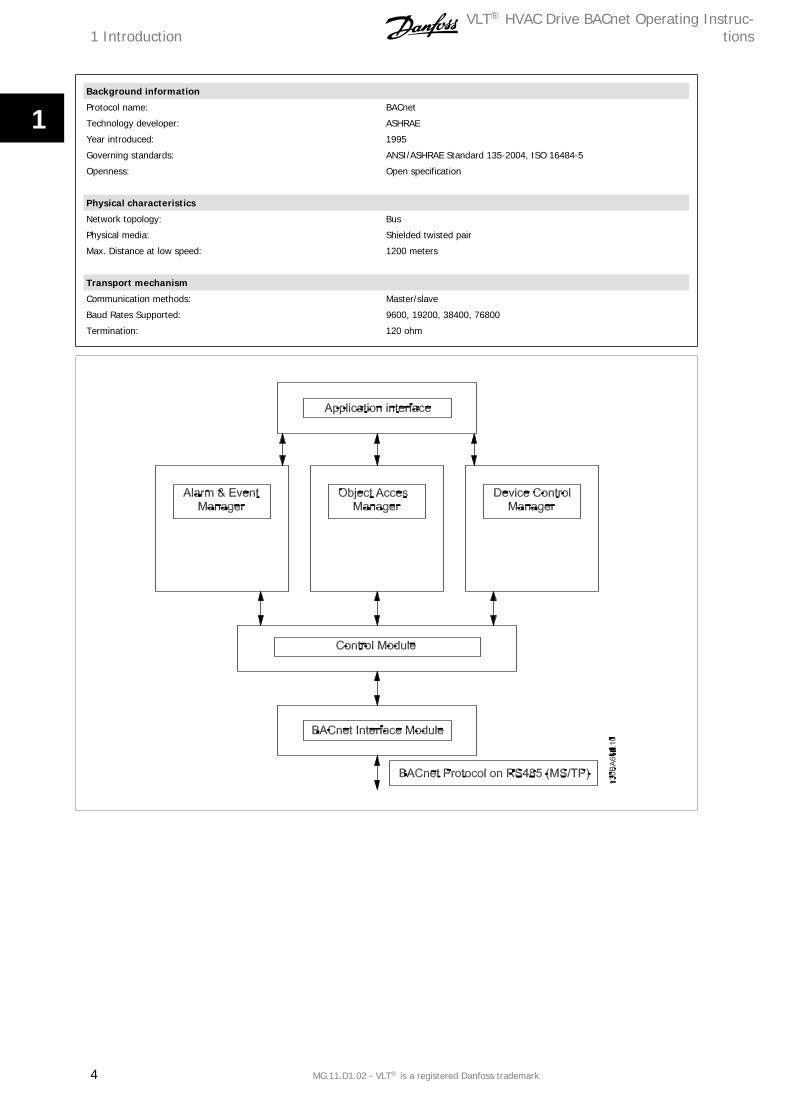
Background information
Protocol name: BACnet
Technology developer: ASHRAE
Year introduced: 1995
Governing standards: ANSI/ASHRAE Standard 135-2004, ISO 16484-5
Openness: Open specification
Physical characteristics
Network topology: Bus
Physical media: Shielded twisted pair
Max. Distance at low speed: 1200 meters
Transport mechanism
Communication methods: Master/slave
Baud Rates Supported: 9600, 19200, 38400, 76800
Termination: 120 ohm
1 IntroductionVLT® HVAC Drive BACnet Operating Instruc-
tions
4 MG.11.D1.02 - VLT® is a registered Danfoss trademark
1

1.1.3 Assumptions
This manual assumes you are using a Danfoss BACnet Option Card in
conjunction with a Danfoss FC 100 series frequency converter. It is also
assumed that your master is a BMS or PC equipped with a serial com-
munication card supporting all the BACnet communication services re-
quired by your application, and that all requirements stipulated in the
BACnet standard, as well as those pertaining to the VLT Variable Speed
Drive are strictly observed as well as all limitations therein fully respected.
1.1.4 Background Knowledge
The Danfoss BACnet Option Card is designed to communicate with any
master complying with the BACnet standard. Familiarity with the PC or
PLC used as a master in the system is assumed. Issues regarding hard-
ware or software produced by other manufacturers are beyond the scope
of this manual and are not the responsibility of Danfoss.
If you have questions regarding set-up of master-to-master communica-
tion or communication to a non-Danfoss slave, please consult the appro-
priate manuals.
1.1.5 Available literature
- Operating Instructions MG.11.Ax.yy provide the neccessary information for getting the frequency converter up and running.
- Design Guide MG.11.Bx.yy entails all technical information about the frequency converter and customer design and applications.
- Programming Guide MG.11.Cx.yy provides information on how to programme and includes complete parameter descriptions.
- Mounting Instruction, Analog I/O Option MCB109, MI.38.Bx.yy
- PC-based Configuration Tool MCT 10, MG.10.Ax.yy enables the user to configure the frequency converter from a Windows™ based PC environ-
ment.
- VLT® Energy Box software at www.danfoss.com/BusinessAreas/DrivesSolutions then choose PC Software Download
- VLT® HVAC Drive Applications, MG.11.Tx.yy
- Operating Instructions BACnet, MG.11.Dx.yy
- Operating Instructions Profibus, MG.33.Cx.yy.
- Operating Instructions Device Net, MG.33.Dx.yy
- Operating Instructions LonWorks, MG.11.Ex.yy
- Operating Instructions High Power, MG.11.Fx.yy
- Operating Instructions Metasys, MG.11.Gx.yy
- Operating Instructions FLN, MG.11.Zx.yy
x = Revision number
yy = Language code
technical literature is available in print from your local Sales Office or online at:
www.danfoss.com/BusinessAreas/DrivesSolutions/Documentations/Technical+Documentation.htm
VLT® HVAC Drive BACnet Operating Instruc-tions 1 Introduction
MG.11.D1.02 - VLT® is a registered Danfoss trademark 5
1

1.1.6 Abbreviations
ACI Acyclical Control Interval PCD Process Data
AOC Application Orientated Controller PCA Parameter Characteristics
BMS Building Management System PCV Parameter-Characteristics-Value
CAN Controller Area Network PDU Protocol Data Unit
CTW Control Word PLC Programmable Logic Control
EEPROM Electrical Erasable Programmable Read Only Memory PNU Parameter Number
EIA Electronic Industries Association: Specifies of the EIA Standard RS 485-A PVA Parameter Value
EMC Electromagnetic Compatibility RC Request/Response Characteristics
FDL Fieldbus Data link Layer STW Status Word
FDT Field Device Tool
IND Sub index
I/O Input/Output
ISO International Standards Organization
LCD Liquid Crystal Display
LCP Local Control Panel
LED Light Emitting Diode
MAV Main Actual Value
MOC Motion Orientated Controller
MRV Main Reference Value
PC Personal Computer
1 IntroductionVLT® HVAC Drive BACnet Operating Instruc-
tions
6 MG.11.D1.02 - VLT® is a registered Danfoss trademark
1

2 Safety
2.1 Safety
2.1.1 Copyright, Limitation of Liability and Revision Rights
This publication contains information proprietary to . By accepting and using this manual the user agrees that the information contained herein will be
used solely for operating equipment from or equipment from other vendors provided that such equipment is intended for communication with equipment
over a serial communication link. This publication is protected under the Copyright laws of Denmark and most other countries.
does not warrant that a software program produced according to the guidelines provided in this manual will function properly in every physical, hardware
or software environment.
Although has tested and reviewed the documentation within this manual, makes no warranty or representation, neither expressed nor implied, with
respect to this documentation, including its quality, performance, or fitness for a particular purpose.
In no event shall be liable for direct, indirect, special, incidental, or consequential damages arising out of the use, or the inability to use information
contained in this manual, even if advised of the possibility of such damages. In particular, is not responsible for any costs, including but not limited to
those incurred as a result of lost profits or revenue, loss or damage of equipment, loss of computer programs, loss of data, the costs to substitute these,
or any claims by third parties.
reserves the right to revise this publication at any time and to make changes to its contents without prior notice or any obligation to notify former or
present users of such revisions or changes.
VLT® HVAC Drive BACnet Operating Instruc-tions 2 Safety
MG.11.D1.02 - VLT® is a registered Danfoss trademark 7
2
2.1.2 Safety Precautions
The voltage of the frequency converter is dangerous whenever connected to mains. Incorrect installation of the motor, frequency
converter or fieldbus may cause damage to the equipment, serious personal injury or death. Consequently, the instructions in this
manual, as well as national and local rules and safety regulations, must be complied with.
Safety Regulations
1. The mains supply to the frequency converter must be disconnected whenever repair work is to be carried out. Check that the mains supply has
been disconnected and that the necessary time has elapsed before removing motor and mains supply plugs.
2. The [OFF] button on the control panel of the frequency converter does not disconnect the mains supply and consequently it must not be used
as a safety switch.
3. The equipment must be properly earthed, the user must be protected against supply voltage and the motor must be protected against overload
in accordance with applicable national and local regulations.
4. The earth leakage current exceeds 3.5 mA.
5. Protection against motor overload is not included in the factory setting. If this function is desired, set par. to data value ETR trip 1 [4] or data
value ETR warning 1 [3].
6. Do not remove the plugs for the motor and mains supply while the frequency converter is connected to mains. Check that the mains supply has
been disconnected and that the necessary time has elapsed before removing motor and mains plugs.
7. Please note that the frequency converter has more voltage sources than L1, L2 and L3, when load sharing (linking of DC intermediate circuit)
or external 24 V DC are installed. Check that all voltage sources have been disconnected and that the necessary time has elapsed before
commencing repair work.
Warning against unintended start
1. The motor can be brought to a stop by means of digital commands, bus commands, references or a local stop, while the frequency converter
is connected to mains. If personal safety considerations (e.g. risk of personal injury caused by contact with moving machine parts following an
unintentional start) make it necessary to ensure that no unintended start occurs, these stop functions are not sufficient. In such cases the mains
supply must be disconnected or the Safe Stop function must be activated.
2. The motor may start while setting the parameters. If this means that personal safety may be compromised (e.g. personal injury caused by
contact with moving machine parts), motor starting must be prevented, for instance by use of the Safe Stop function or secure disconnection
of the motor connection.
3. A motor that has been stopped with the mains supply connected, may start if faults occur in the electronics of the frequency converter, through
temporary overload or if a fault in the power supply grid or motor connection is remedied. If unintended start must be prevented for personal
safety reasons (e.g. risk of injury caused by contact with moving machine parts), the normal stop functions of the frequency converter are not
sufficient. In such cases the mains supply must be disconnected or the Safe Stop function must be activated.
NB!
When using the Safe Stop function, always follow the instructions in the Safe Stop section of the Design Guide.
4. Control signals from, or internally within, the frequency converter may in rare cases be activated in error, be delayed or fail to occur entirely.
When used in situations where safety is critical, e.g. when controlling the electromagnetic brake function of a hoist application, these control
signals must not be relied on exclusively.
Touching the electrical parts may be fatal - even after the equipment has been disconnected from mains.
Also make sure that other voltage inputs have been disconnected, such as external 24 V DC, load sharing (linkage of DC intermediate circuit), as well as
the motor connection for kinetic back up.
Systems where frequency converters are installed must, if necessary, be equipped with additional monitoring and protective devices according to the
valid safety regulations, e.g law on mechanical tools, regulations for the prevention of accidents etc. Modifications on the frequency converters by means
of the operating software are allowed.
2 SafetyVLT® HVAC Drive BACnet Operating Instruc-
tions
8 MG.11.D1.02 - VLT® is a registered Danfoss trademark
2

Hoisting applications:
The frequency converter functions for controlling mechanical brakes cannot be considered as a primary safety circuit. There must always be a redundancy
for controlling external brakes.
Protection Mode
Once a hardware limit on motor current or dc-link voltage is exceeded the drive will enter “Protection mode”. “Protection mode” means a change of the
PWM modulation strategy and a low switching frequency to minimize losses. This continues 10 sec after the last fault and increases the reliability and
the robustness of the drive while re-establishing full control of the motor.
In hoist applications “Protection mode” is not usable because the drive will usually not be able to leave this mode again and therefore it will extend the
time before activating the brake – which is not recommendable.
The “Protection mode” can be disabled by setting par. to zero which means that the drive will trip immediately if one of the hardware limits is exceeded.
NB!
It is recommended to disable protection mode in hoisting applications (par. = 0)
VLT® HVAC Drive BACnet Operating Instruc-tions 2 Safety
MG.11.D1.02 - VLT® is a registered Danfoss trademark 9
2
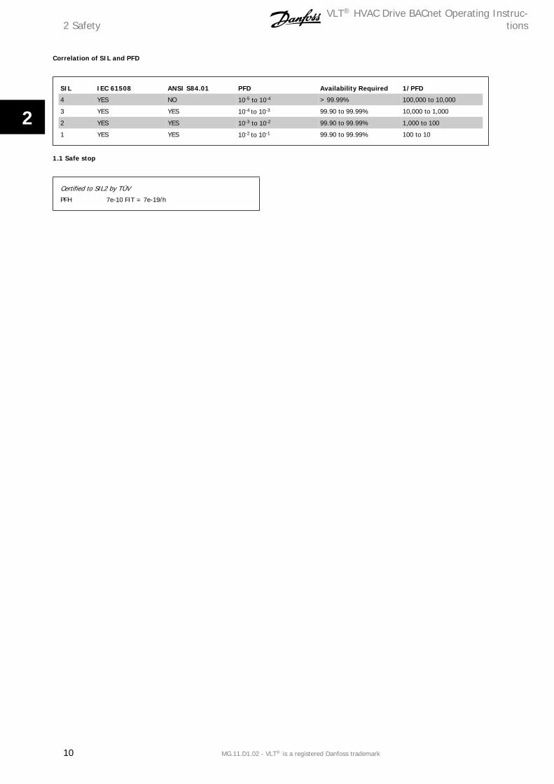
Correlation of SIL and PFD
SIL IEC 61508 ANSI S84.01 PFD Availability Required 1/PFD
4 YES NO 10-5 to 10-4 > 99.99% 100,000 to 10,000
3 YES YES 10-4 to 10-3 99.90 to 99.99% 10,000 to 1,000
2 YES YES 10-3 to 10-2 99.90 to 99.99% 1,000 to 100
1 YES YES 10-2 to 10-1 99.90 to 99.99% 100 to 10
1.1 Safe stop
Certified to SIL2 by TÜV
PFH 7e-10 FIT = 7e-19/h
2 SafetyVLT® HVAC Drive BACnet Operating Instruc-
tions
10 MG.11.D1.02 - VLT® is a registered Danfoss trademark
2
3 How to Install
3.1 The BACnet Option
3.1.1 Installation of the Option
Items required to install a fieldbus option in the frequency converter:
- - The fieldbus option
- - Fieldbus option adaptor frame for the frequency converter. This frame is deeper than the standard frame, to allow space for the fieldbus option
beneath.
VLT® HVAC Drive BACnet Operating Instruc-tions 3 How to Install
MG.11.D1.02 - VLT® is a registered Danfoss trademark 11
3
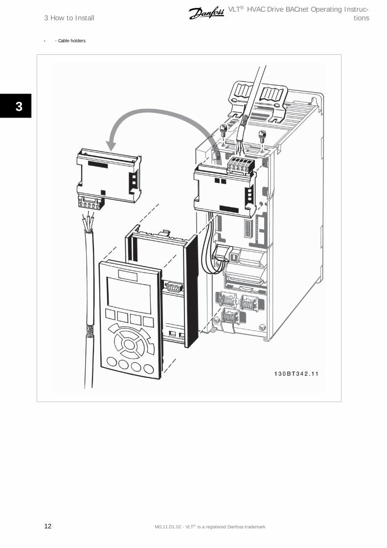
- - Cable holders
3 How to InstallVLT® HVAC Drive BACnet Operating Instruc-
tions
12 MG.11.D1.02 - VLT® is a registered Danfoss trademark
3

Instructions:
- - Remove the LCD panel from the frequency converter.
- - Remove the frame located beneath and discard.
- - Push the option into place. Two positions are possible, with cable terminal facing either up or down. The cable up position is often most suitable
when several frequency converters are installed side by side in a rack, as this position permits shorter cable lengths.
- - Push the fieldbus option adaptor frame for the frequency converter into place.
- - Remove the Plug for the FC Port and connect the Plug that is connected to the BACnet Option
- - Replace the LCD panel.
- - Attach cable.
- - Fasten the cable in place using cable holders. The frequency converter top surface has pre-drilled threaded holes for attaching the cable holders
to the unit.
VLT® HVAC Drive BACnet Operating Instruc-tions 3 How to Install
MG.11.D1.02 - VLT® is a registered Danfoss trademark 13
3
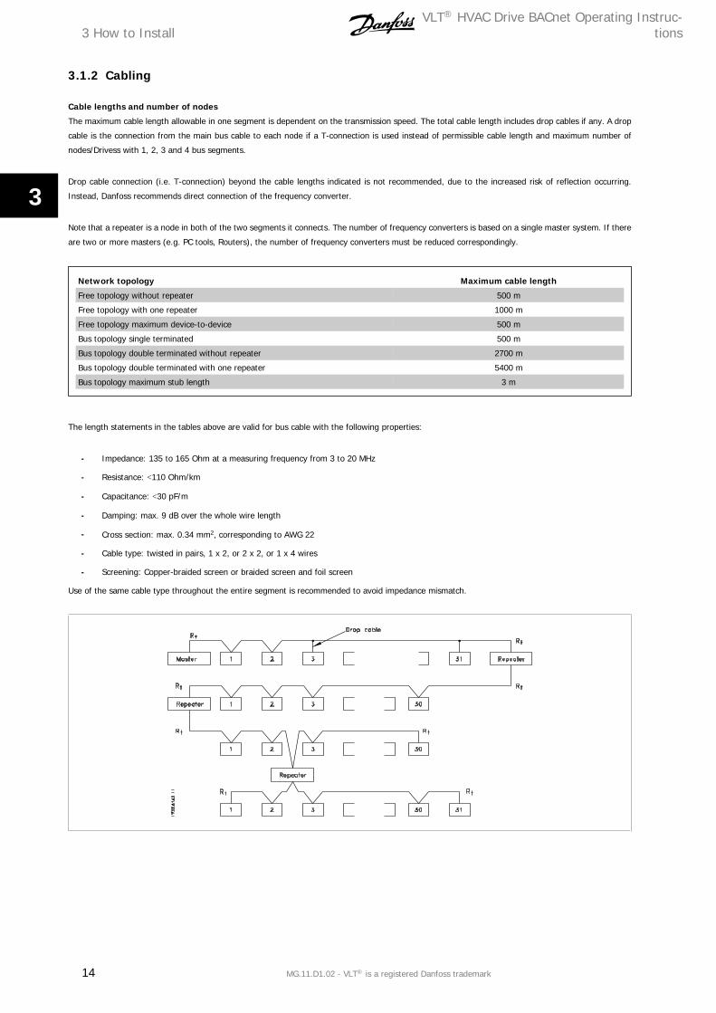
3.1.2 Cabling
Cable lengths and number of nodes
The maximum cable length allowable in one segment is dependent on the transmission speed. The total cable length includes drop cables if any. A drop
cable is the connection from the main bus cable to each node if a T-connection is used instead of permissible cable length and maximum number of
nodes/Drivess with 1, 2, 3 and 4 bus segments.
Drop cable connection (i.e. T-connection) beyond the cable lengths indicated is not recommended, due to the increased risk of reflection occurring.
Instead, Danfoss recommends direct connection of the frequency converter.
Note that a repeater is a node in both of the two segments it connects. The number of frequency converters is based on a single master system. If there
are two or more masters (e.g. PC tools, Routers), the number of frequency converters must be reduced correspondingly.
Network topology Maximum cable length
Free topology without repeater 500 m
Free topology with one repeater 1000 m
Free topology maximum device-to-device 500 m
Bus topology single terminated 500 m
Bus topology double terminated without repeater 2700 m
Bus topology double terminated with one repeater 5400 m
Bus topology maximum stub length 3 m
The length statements in the tables above are valid for bus cable with the following properties:
- Impedance: 135 to 165 Ohm at a measuring frequency from 3 to 20 MHz
- Resistance: <110 Ohm/km
- Capacitance: <30 pF/m
- Damping: max. 9 dB over the whole wire length
- Cross section: max. 0.34 mm2, corresponding to AWG 22
- Cable type: twisted in pairs, 1 x 2, or 2 x 2, or 1 x 4 wires
- Screening: Copper-braided screen or braided screen and foil screen
Use of the same cable type throughout the entire segment is recommended to avoid impedance mismatch.
3 How to InstallVLT® HVAC Drive BACnet Operating Instruc-
tions
14 MG.11.D1.02 - VLT® is a registered Danfoss trademark
3
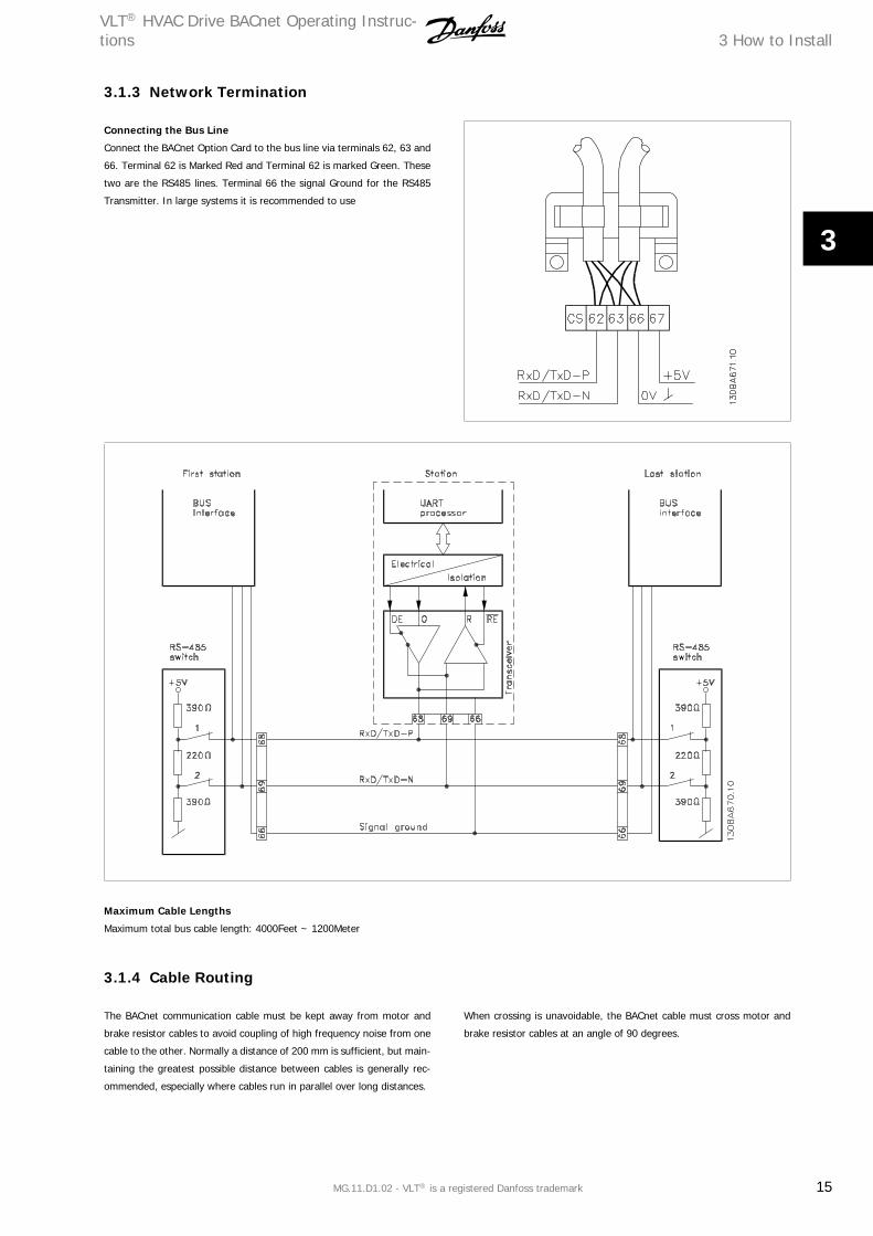
3.1.3 Network Termination
Connecting the Bus Line
Connect the BACnet Option Card to the bus line via terminals 62, 63 and
66. Terminal 62 is Marked Red and Terminal 62 is marked Green. These
two are the RS485 lines. Terminal 66 the signal Ground for the RS485
Transmitter. In large systems it is recommended to use
Maximum Cable Lengths
Maximum total bus cable length: 4000Feet ~ 1200Meter
3.1.4 Cable Routing
The BACnet communication cable must be kept away from motor and
brake resistor cables to avoid coupling of high frequency noise from one
cable to the other. Normally a distance of 200 mm is sufficient, but main-
taining the greatest possible distance between cables is generally rec-
ommended, especially where cables run in parallel over long distances.
When crossing is unavoidable, the BACnet cable must cross motor and
brake resistor cables at an angle of 90 degrees.
VLT® HVAC Drive BACnet Operating Instruc-tions 3 How to Install
MG.11.D1.02 - VLT® is a registered Danfoss trademark 15
3

3.2 System Specifications
3.2.1 EMC Precautions
The following EMC precautions are recommended to achieve interfer-
ence-free operation of the BACnet network. Additional EMC information
is available in the VLT® HVAC Drive Design Guide, MG.11.Bx.yy. Please
also consult the BACnet master manual for further installation guidelines.
NB!
Ensure compliance with relevant national and local regulations, for example in protective earth connection.
3.2.2 Connection of the Cable Screen
It is recommended to connect the screen to ground in both end of the
Bus Cable. This ensures the optimum resistance towards EMC noise.
screen of the BACnet cable must always be connected to ground at both
ends, meaning the screen must be connected to ground in all stations
connected to the BACnet network. It is very important to have a low im-
pedance ground connection of the screen, also at high frequencies. This
can be obtained by connecting the surface of the screen to ground, for
example by means of a cable clamp or a conductive cable gland. The FC
100 Series has various clamps and brackets to enable a proper ground
connection of the BACnet cable screen.
3.2.3 Earth Connection
It is important that all stations connected to the BACnet network are
connected to the same earth potential. The earth connection must have
low HF (high frequency) impedance. This can be achieved by connecting
a large surface area of the cabinet to earth, for example by mounting the
FC 100 series on a conductive rear plate. Particularly when there are long
distances between the stations in a BACnet network, it can be necessary
to use additional potential equalizing cables, connecting the individual
stations to the same earth potential. The use of Repeaters with galvanic
isolation or Fibre optic can improve the EMC performance and reduce
Ground loop Current.
3 How to InstallVLT® HVAC Drive BACnet Operating Instruc-
tions
16 MG.11.D1.02 - VLT® is a registered Danfoss trademark
3
4 How to Configure the System
4.1 Configuring BACnet
4.1.1 Initialization Procedure
The Initialization Procedure is explained by the flow chart given below:
Initialization Parameter
General Settings
NameParameter
NumberDefault Value Setting for BACnet
Control Site 8-01 Digital and control word Digital and control word
Control word source 8-02 FC RS-485 FC RS-485
ControlWord Timeout time 8-03 1.0 sec 1.0 sec
ControlWord Timeout Function 8-04 Off Off
End of Timeout Function 8-05 Resume setup Resume setup
Reset ControlWord Timeout 8-06 Do not reset Do not reset
Diagnosis 8-07 Set up Don’t care
ControlWord Profile 8-10 FC Profile FC Profile
FC Port Settings
NameParameter
NumberDefault Value Setting for BACnet
Protocol 8-30 FC FC Option
Address 8-31 1 1
Baud Rate 8-32 9600 baud 9600 baud
Minimum Response Delay 8-35 10 ms 10 ms
Max Response Delay 8-36 5000 ms 5000 ms
Table 4.1: 1) Please see also section: Parameter Overview >Parameter List.
VLT® HVAC Drive BACnet Operating Instruc-tions 4 How to Configure the System
MG.11.D1.02 - VLT® is a registered Danfoss trademark 17
4

Digital/Bus settings
NameParameter
NumberDefault Value Setting for BACnet
Coasting Select 8-50 Logic-or Logic-or
Quick Stop Select 8-51 Logic-or Logic-or
DC Brake Select 8-52 Logic-or Logic-or
Start Select 8-53 Logic-or Logic-or
Reversing Select 8-54 Logic-or Logic-or
Set-up Select 8-55 Logic-or Logic-or
Preset reference Select 8-56 Logic-or Logic-or
BACnet settings
NameParameter
NumberDefault Value Setting for BACnet
BACnet device Instance 8-71 1 1
MS/TP Max Masters 8-73 127Depent on the Number of Mas-
ters in the system
I am transmit time 8-74 At power up At power up
Initialisation Password 8-75 “admin” “admin”
4.1.2 Control Word Time-out Function
Par. 8-03 Control Word Timeout Time and par. 8-04 Control Word Timeout Function are not enabled in this version of the BACnet option.
4.2 BIBBs
4.2.1 Bibb's
ReadProperty Service
ReadPropertyMultiple Service
WriteProperty Service
WritePropertyMultiple Service
ConfirmedEventNotification Service
UnconfirmedEventNotification Service
GetEventInformation Service
AcknowledgeAlarm Service
ReinitializeDevice Service
DeviceCommunicationControl Service
I-Have Service
Who-Has Service
Who-Is Service
I-am Service
TimeSynchronization
4 How to Configure the SystemVLT® HVAC Drive BACnet Operating Instruc-
tions
18 MG.11.D1.02 - VLT® is a registered Danfoss trademark
4
4.3 Example of a simple setup of BACnetThis example shows the necessary steps to set up the FC102 BACnet interface with the following system requirements:
• • MS/TP running at 38.400 Baud
• • MAC address 20 for the FC102
• • BACnet Device Instance 0 1025
• • Highest number of a Master stack is 35
• • Start/stop of FC from BACnet only
• • Reference from BACnet
• • Read status of FC (Actual speed)
Set the following parameters:
Name Parameter number Value
Protocol 8-30 FC option [9]
Address 8-31 20
FC Port Baud Rate 8-32 38,400 Baud [4]
Coasting Select 8-50 Bus [1]
BACnet device Instance 8-70 1025
MS/TP Max Masters 8-72 35
After the parameters have been set according the table above, the drive has to be unpowered and repowered before the changes take effect. When the
frequency converter is detected by the BMS, the drive can be controlled by BV:1, which will start the motor if set to [1]. Setting AV:0 will set the speed
reference of the drive. The actual speed can be monitored via AV:1. See also Analog Input- and Output Objects section.
VLT® HVAC Drive BACnet Operating Instruc-tions 4 How to Configure the System
MG.11.D1.02 - VLT® is a registered Danfoss trademark 19
4
5 How to Control the Frequency ConverterVLT® HVAC Drive BACnet Operating Instruc-
tions
20 MG.11.D1.02 - VLT® is a registered Danfoss trademark
5
5 How to Control the Frequency Converter
5.1.1 Reference Handling
Select the frequency converter configuration mode in par. 1-00 Configuration Mode.
[0] Open Loop
[3] Closed Loop
Open Loop
For open loop operation, the reference represents the desired output speed of the frequency converter.
The speed reference value:
Closed Loop
For closed loop operation, the reference represents the setpoint.
NB!
In closed loop operation, par. 3-02 Minimum Reference and par. 4-12 Motor Speed Low Limit must be set to 0 Hz. Set the par. 4-14
Motor Speed High Limit to a value greater than the setting in par. 3-03 Maximum Reference.
5.2 Network Frequency Converter Control Inputs and -Outputs
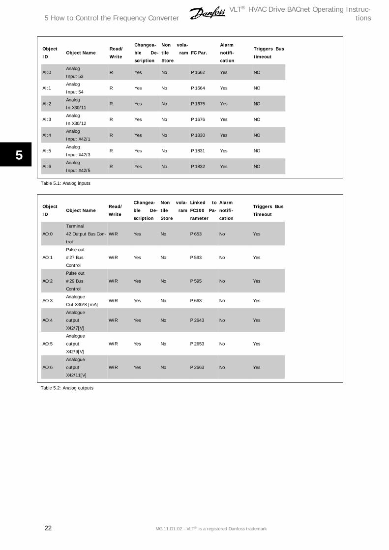
5.2.1 Analog Input- and Output Objects
Control the frequency converter from the BACnet network using 'objects'. The various types of 'objects' and their descriptions are shown in the following
tables.
VLT® HVAC Drive BACnet Operating Instruc-tions 5 How to Control the Frequency Converter
MG.11.D1.02 - VLT® is a registered Danfoss trademark 21
5
Object
IDObject Name
Read/
Write
Changea-
ble De-
scription
Non vola-
tile ram
Store
FC Par.
Alarm
notifi-
cation
Triggers Bus
timeout
AI:0Analog
Input 53R Yes No P 1662 Yes NO
AI:1Analog
Input 54R Yes No P 1664 Yes NO
AI:2Analog
In X30/11R Yes No P 1675 Yes NO
AI:3Analog
In X30/12R Yes No P 1676 Yes NO
AI:4Analog
Input X42/1R Yes No P 1830 Yes NO
AI:5Analog
Input X42/3R Yes No P 1831 Yes NO
AI:6Analog
Input X42/5R Yes No P 1832 Yes NO
Table 5.1: Analog inputs
Object
IDObject Name
Read/
Write
Changea-
ble De-
scription
Non vola-
tile ram
Store
Linked to
FC100 Pa-
rameter
Alarm
notifi-
cation
Triggers Bus
Timeout
AO:0
Terminal
42 Output Bus Con-
trol
W/R Yes No P 653 No Yes
AO:1
Pulse out
#27 Bus
Control
W/R Yes No P 593 No Yes
AO:2
Pulse out
#29 Bus
Control
W/R Yes No P 595 No Yes
AO:3Analogue
Out X30/8 [mA]W/R Yes No P 663 No Yes
AO:4
Analogue
output
X42/7[V]
W/R Yes No P 2643 No Yes
AO:5
Analogue
output
X42/9[V]
W/R Yes No P 2653 No Yes
AO:6
Analogue
output
X42/11[V]
W/R Yes No P 2663 No Yes
Table 5.2: Analog outputs
5 How to Control the Frequency ConverterVLT® HVAC Drive BACnet Operating Instruc-
tions
22 MG.11.D1.02 - VLT® is a registered Danfoss trademark
5
Object
IDObject Name
Read/
Write
Changea-
ble De-
scription
Non vola-
tile ram
Store
FC100 Pa-
rameter
Alarm
notifi-
cation
Triggers Bus
Timeout
AV:0 Reference W/R Yes No MRV No Yes
AV:1 Speed Act. Value W/R Yes No MAV Yes Yes
AV:2 Bus Feedback1 W/R Yes No P 894 No Yes
AV:3 Bus Feedback2 W/R Yes No P 895 No Yes
AV:4 Bus Feedback3 W/R Yes No P 896 No Yes
AV:5 Motor Voltage Read Yes No P 1612 Yes No
AV:6 Motor Current Read Yes No P 1614 Yes No
AV:7 Motor Torque % Read Yes No P 1622 Yes No
AV:8 DC Link Voltage Read Yes No P 1630 Yes No
AV:9 Motor thermal Read Yes No P 1618 Yes No
AV:10Heat sink Tempera-
tureRead Yes No P 1634 Yes No
AV:11 Inverter Thermal Read Yes No P 1635 Yes No
AV:12 Operating Hours Read No No P 1500 No No
AV:13 Running Hours Read No No P 1501 No No
AV:14 KWh Counter Read No No P 1502 No No
AV:15 Power [KW] Read No No P 1610 No No
AV:16PID Start Speed
[Hz]W/R No FC 100 P 2083 No No
AV:17PID Proportional
GainW/R No FC 100 P 2093 No No
AV:18PID Integral Time
(Sec)W/R No FC 100 P 20-94 No No
AV:19PID Differential
Time (Sec)W/R No FC 100 P 20-95 No No
AV:20 PID Dif. Gain Limit W/R No FC 100 P 20-96 No No
AV:21On Reference Band-
withW/R No FC 100 P 20-84 No No
AV:22 Ext. 1 Setpoint W/R No FC 100 P 2115 No No
AV:23Ext. 1 Reference
[Unit]W/R No FC 100 P 2117 No No
AV:24Ext. 1 Feedback
[Unit]W/R No FC 100 P 2118 No No
AV:25Ext. 1 Propotional
GainW/R No FC 100 P 2121 No No
AV:26 Reserved W/R No Na
AV:27Ext. 1 Integral Time
(Sec)W/R No FC 100 P 2122 No No
AV:28Ext. 1 Differential
Time (Sec)W/R No FC 100 P 2123 No No
AV:29 Ext. 1 Dif. Gain Limit W/R No FC 100 P 2124 No No
AV:30 Reserved W/R No Na
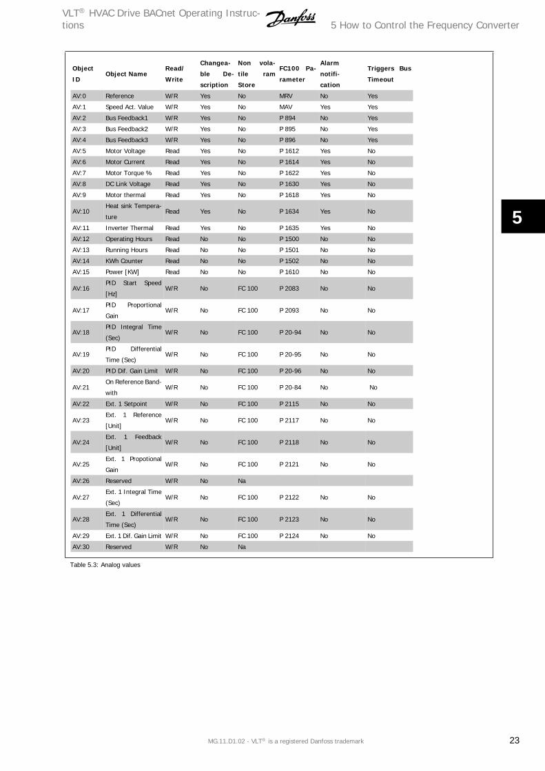
Table 5.3: Analog values
VLT® HVAC Drive BACnet Operating Instruc-tions 5 How to Control the Frequency Converter
MG.11.D1.02 - VLT® is a registered Danfoss trademark 23
5
Object
IDObject Name
Read/
Write
Changea-
ble De-
scription
Non vola-
tile ram
Store
FC100 Pa-
rameter
Alarm
notifi-
cation
Triggers Bus
Timeout
AV:31 Ext. 2 Setpoint W/R No FC 100 P 2135 No No
AV:32Ext. 2 reference
[Unit]W/R No FC 100 P 2137 No No
AV:33Ext. 2 Feedback
[Unit]W/R No FC 100 P 2138 No No
AV:34Ext. 2 Proportional
GainW/R No FC 100 P 2141 No No
AV:35Ext. 2 Integral Time
(Sec)W/R No FC 100 P 2142 No No
AV:36Ext. 2 Differential
TimeW/R No FC 100 P 2143 No No
AV:37 Ext. 2 Dif. Gain W/R No FC 100 P 2144 No No
AV:38 Ext. 3 Setpoint W/R No FC 100 P 2155 No No
AV:39Ext. 3 Reference
[Unit]W/R No FC 100 P 2157 No No
AV:40Ext. 3 Feedback
[Unit]W/R No FC 100 P 2158 No No
AV:41Ext. 3 Proportional
GainW/R No FC 100 P 2161 No No
AV:42Ext. 3 Integral Time
(Sec)W/R No FC 100 P 2162 No No
AV:43Ext. 3 Differential
Time (Sec)W/R No FC 100 P 2163 No No
AV:44 Ext. 3 Dif. Gain Limit W/R No FC 100 P 2164 No No
AV:45 Running Bypass Read No No P 3111 No No
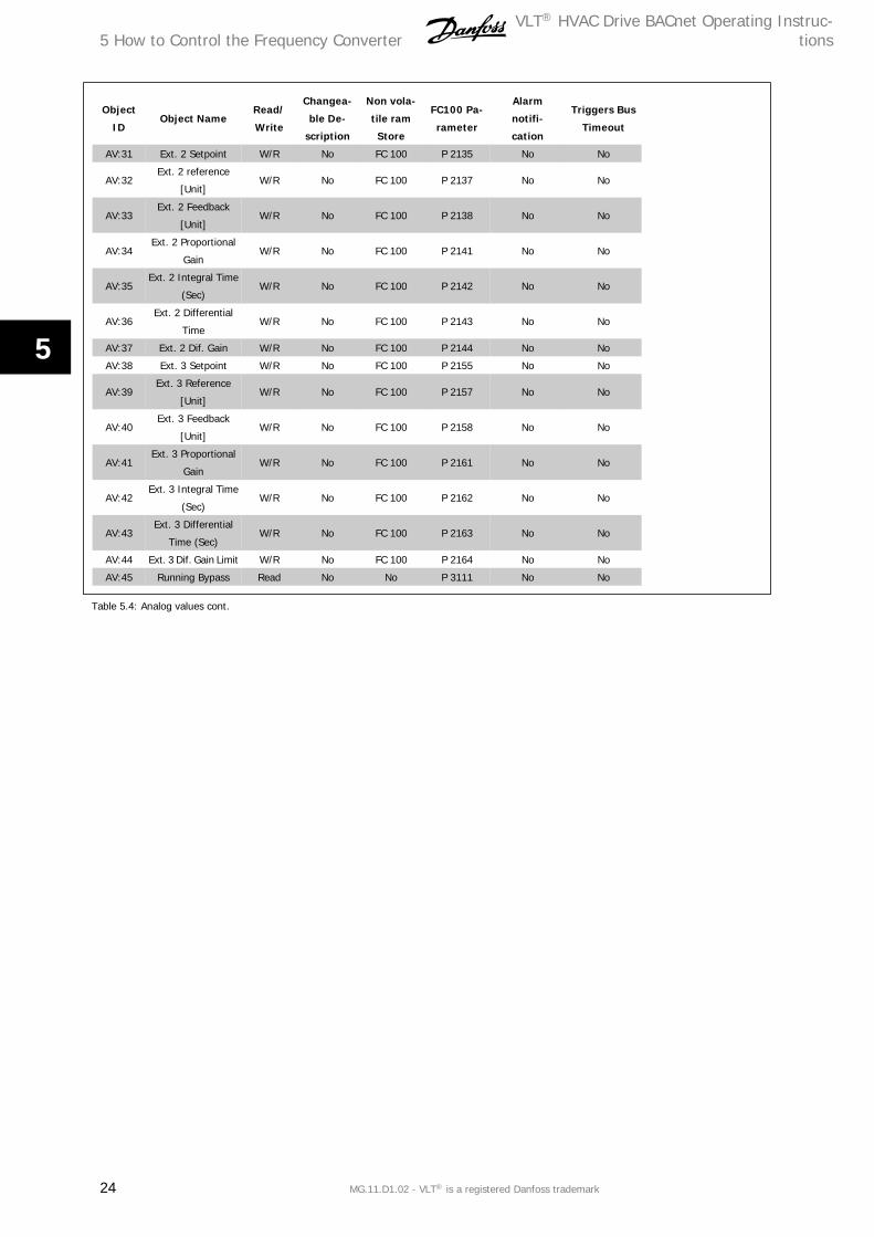
Table 5.4: Analog values cont.
5 How to Control the Frequency ConverterVLT® HVAC Drive BACnet Operating Instruc-
tions
24 MG.11.D1.02 - VLT® is a registered Danfoss trademark
5
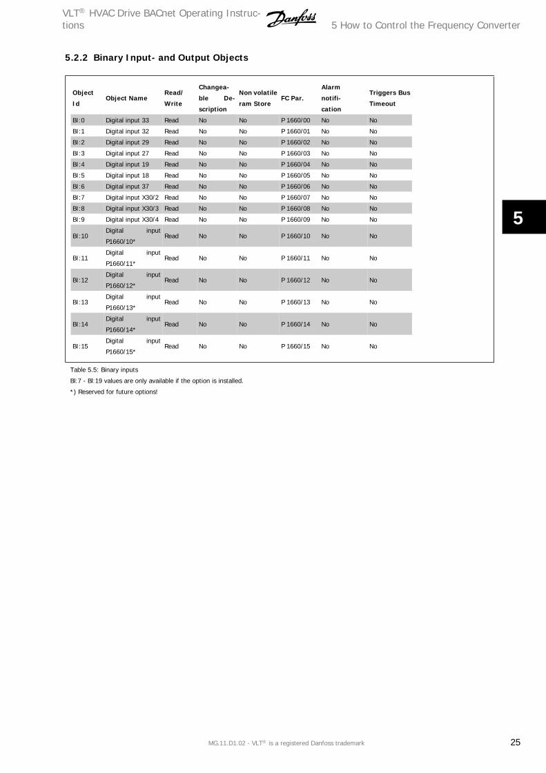
5.2.2 Binary Input- and Output Objects
Object
IdObject Name
Read/
Write
Changea-
ble De-
scription
Non volatile
ram StoreFC Par.
Alarm
notifi-
cation
Triggers Bus
Timeout
BI:0 Digital input 33 Read No No P 1660/00 No No
BI:1 Digital input 32 Read No No P 1660/01 No No
BI:2 Digital input 29 Read No No P 1660/02 No No
BI:3 Digital input 27 Read No No P 1660/03 No No
BI:4 Digital input 19 Read No No P 1660/04 No No
BI:5 Digital input 18 Read No No P 1660/05 No No
BI:6 Digital input 37 Read No No P 1660/06 No No
BI:7 Digital input X30/2 Read No No P 1660/07 No No
BI:8 Digital input X30/3 Read No No P 1660/08 No No
BI:9 Digital input X30/4 Read No No P 1660/09 No No
BI:10Digital input
P1660/10*Read No No P 1660/10 No No
BI:11Digital input
P1660/11*Read No No P 1660/11 No No
BI:12Digital input
P1660/12*Read No No P 1660/12 No No
BI:13Digital input
P1660/13*Read No No P 1660/13 No No
BI:14Digital input
P1660/14*Read No No P 1660/14 No No
BI:15Digital input
P1660/15*Read No No P 1660/15 No No
Table 5.5: Binary inputs
Bl:7 - Bl:19 values are only available if the option is installed.
*) Reserved for future options!
VLT® HVAC Drive BACnet Operating Instruc-tions 5 How to Control the Frequency Converter
MG.11.D1.02 - VLT® is a registered Danfoss trademark 25
5
Object
IdObject Name
Read/
Write
Changea-
ble De-
scription
Non vola-
tile ram
Store
FC Par.
Alarm
notifi-
cation
Triggers Bus
Timeout
BO:0 Digital output 27 W/R No No P 590/00 No Yes
BO:1 Digital output 29 W/R No No P 590/01 No Yes
BO:2GPIO Output Term
X30/6W/R No No P 590/02 No Yes
BO:3GPIO Output Term
X30/7W/R No No P 590/03 No Yes
BO:4 Relay 1 output W/R No No P 590/04 No Yes
BO:5 Relay 2 output W/R No No P 590/05 No Yes
BO:6Option B Relay 1
outputW/R No No P 590/06 No Yes
BO:7Option B Relay 2
outputW/R No No P 590/07 No Yes
BO:8Option B Relay 3
outputW/R No No P 590/08 No Yes
BO:9Reserved output
P590/9W/R No No P 590/09 No Yes
BO:10Reserved output
P590/10*W/R No No P 590/10 No Yes
BO:11Reserved output
P590/11*W/R No No P 590/11 No Yes
BO:12Reserved output
P590/12*W/R No No P 590/12 No Yes
BO:13Reserved output
P590/13*W/R No No P 590/13 No Yes
BO:14Reserved output
P590/14*W/R No No P 590/14 No Yes
BO:15Reserved output
P590/15*W/R No No P 590/15 No Yes
BO:16Option C Relay 1
outputW/R No No P 590/16 No Yes
BO:17Option C Relay 2
outputW/R No No P 590/17 No Yes
BO:18Option C Relay 3
outputW/R No No P 590/18 No Yes
BO:19Option C Relay 4
outputW/R No No P 590/19 No Yes
BO:20Option C Relay 5
outputW/R No No P 590/20 No Yes
BO:21Option C Relay 6
outputW/R No No P 590/21 No Yes
BO:22Option C Relay 7
outputW/R No No P 590/22 No Yes
BO:23Option C Relay 8
outputW/R No No P 590/23 No Yes
BO:24Reserved output
P590/24*W/R No No P 590/24 No Yes
BO:25Reserved output
P590/25*W/R No No P 590/25 No Yes
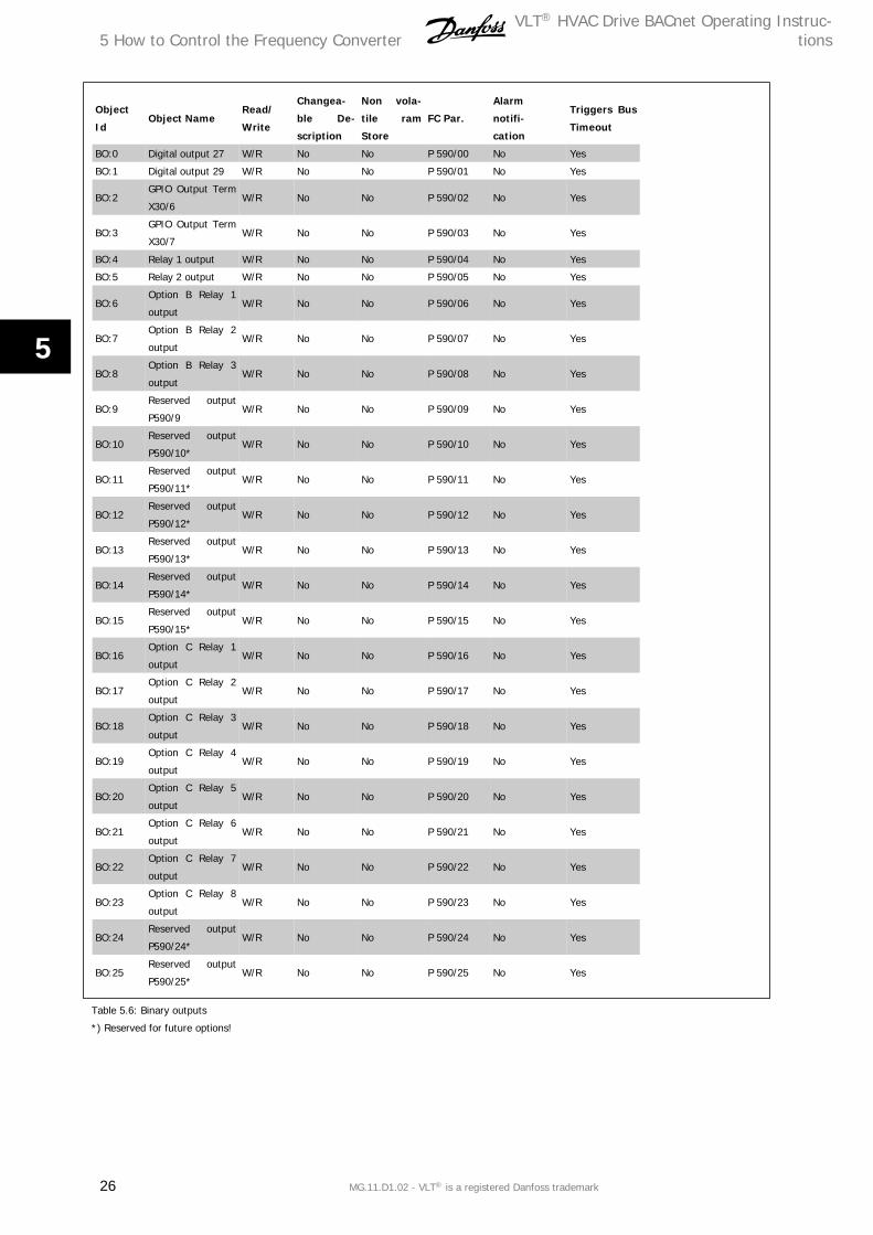
Table 5.6: Binary outputs
*) Reserved for future options!
5 How to Control the Frequency ConverterVLT® HVAC Drive BACnet Operating Instruc-
tions
26 MG.11.D1.02 - VLT® is a registered Danfoss trademark
5
Object
IdObject Name
Read/
Write
Changea-
ble De-
scription
Non vola-
tile ram
Store
FC Par.
Alarm
notifi-
cation
Triggers Bus
Timeout
BO:30Reserved output
P590/30*W/R No No P 590/30 No Yes
BO:31Reserved output
P590/31*W/R No No P 590/31 No Yes
BO:36Reserved output
P590/26*W/R No No P 590/26 No Yes
BO:37Reserved output
P590/27*W/R No No P 590/27 No Yes
BO:38Reserved output
P590/28*W/R No No P 590/28 No Yes
BO:39Reserved output
P590/29*W/R No No P 590/29 No Yes
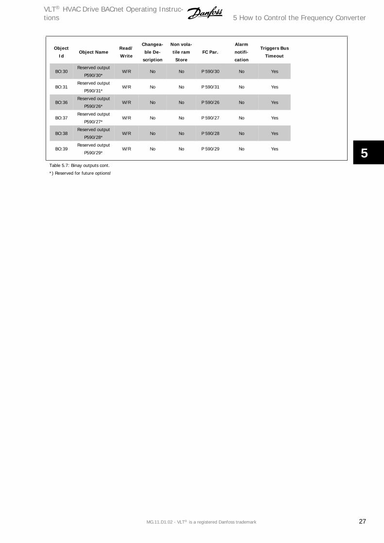
Table 5.7: Binay outputs cont.
*) Reserved for future options!
VLT® HVAC Drive BACnet Operating Instruc-tions 5 How to Control the Frequency Converter
MG.11.D1.02 - VLT® is a registered Danfoss trademark 27
5
Object
IDObject Name
Read /
Write
Changea-
ble De-
scription
Non vola-
tile ram
Store
FC Par.
Alarm
notifi-
cation
Triggers Bus
Timeout
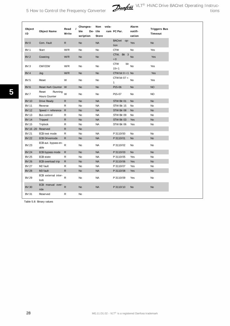
BV:0 Com. Fault R No NABACnet op-
tionYes No
BV:1 Start W/R No No CTW No Yes
BV:2 Coasting W/R No NoCTW, Bit 3
=0No Yes
BV:3 CW/CCW W/R No NoCTW bit
15=1No Yes
BV:4 Jog W/R No No CTW bit 0 =1 No Yes
BV:5 Reset W No NoCTW bit 07 =
1No Yes
BV:6 Reset Kwh Counter W No No P15-06 No NO
BV:7Reset Running
Hours CounterW No No P15-07 No NO
BV:10 Drive Ready R No NA STW Bit 01 No No
BV:11 Reverse R No NA STW Bit 15 No No
BV:12 Speed = reference R No NA STW Bit 08 No No
BV:13 Bus control R No NA STW Bit 09 No No
BV:14 Tripped R No NA STW Bit 03 Yes No
BV:15 Triplock R No NA STW Bit 06 Yes No
BV:16 -20 Reserved R No
BV:21 ECB test mode R No NA P 3110/00 No No
BV:22 ECB Drivemode R No NA P 3110/01 No No
BV:23ECB aut. bypass en-
ableR No NA P 3110/02 No No
BV:24 ECB bypass mode R No NA P 3110/03 No No
BV:25 ECB state R No NA P 3110/05 Yes No
BV:26 ECB overload trip R No NA P 3110/06 Yes No
BV:27 M2 fault R No NA P 3110/07 Yes No
BV:28 M3 fault R No NA P 3110/08 Yes No
BV:29ECB external inter-
lockR No NA P 3110/09 Yes No
BV:30ECB manual over-
rideR No NA P 3110/10 No No
BV:31 Reserved R No
Table 5.8: Binary values
5 How to Control the Frequency ConverterVLT® HVAC Drive BACnet Operating Instruc-
tions
28 MG.11.D1.02 - VLT® is a registered Danfoss trademark
5
Object
IDObject Name
Read /
Write
Changea-
ble De-
scription
Non vola-
tile ram
Store
FC Par.
Alarm
notifi-
cation
Triggers Bus
Timeout
BV:40 Brake check R No NA P 1690/00 Yes
BV:41 Pwr. Card Temp R No NA P 1690/01 Yes
BV:42 Earth Fault R No NA P 1690/02 Yes
BV:43 Ctrl.Card Temp R No NA P 1690/03 Yes
BV:44 Ctrl. Word TO R No NA P 1690/04 Yes
BV:45 Over Current R No NA P 1690/05 Yes
BV:46 Torque Limit R No NA P 1690/06 Yes
BV:47 Motor TH Over R No NA P 1690/07 Yes
BV:48 Motor TH Over R No NA P 1690/08 Yes
BV:49 Inverter Overld. R No NA P 1690/09 Yes
BV:50 DC under Volt R No NA P 1690/10 Yes
BV:51 DC over Volt R No NA P 1690/11 Yes
BV:52 Short Circuit R No NA P 1690/12 Yes
BV:53 Inrush Fault R No NA P 1690/13 Yes
BV:54 Mains Fault R No NA P 1690/14 Yes
BV:55 AMA Not OK R No NA P 1690/15 Yes
BV:56 Live Zero Error R No NA P 1690/16 Yes
BV:57 Internal Fault R No NA P 1690/17 Yes
BV:58 Brake Overload R No NA P 1690/18 Yes
BV:59 U Phase Loss R No NA P 1690/19 Yes
BV:60 V Phase Loss R No NA P 1690/20 Yes
BV:61 W Phase Loss R No NA P 1690/21 Yes
BV:62 Fieldbus Fault R No NA P 1690/22 Yes
BV:63 24 V Supply Low R No NA P 1690/23 Yes
BV:64 Mains fault R No NA P 1690/24 Yes
BV:65 1.8V supply low R No NA P 1690/25 Yes
BV:66 Brake Failure R No NA P 1690/26 Yes
BV:67 Brake IGBT R No NA P 1690/27 Yes
BV:68 Option Changed R No NA P 1690/28 Yes
BV:69 Drive Initialized R No NA P 1690/29 Yes
BV:70 Safe Stop R No NA P 1690/30 Yes
BV:71 Brake low R No NA P 1690/31 Yes
BV:72 Service trip 1691/0 R No NA P 1691/00 Yes
BV:73 Service trip 1691/1 R No NA P 1691/01 Yes
BV:74 Service trip 1691/2 R No NA P 1691/02 Yes
BV:75 Service trip 1691/3 R No NA P 1691/03 Yes
BV:76 Service trip 1691/4 R No NA P 1691/04 Yes
BV:77 No flow R No NA P 1691/05 Yes
BV:78 Dry Pump R No NA P 1691/06 Yes
BV:79 Curve end R No NA P 1691/07 Yes
Table 5.9: Binary values cont.
VLT® HVAC Drive BACnet Operating Instruc-tions 5 How to Control the Frequency Converter
MG.11.D1.02 - VLT® is a registered Danfoss trademark 29
5
Object
IDObject Name
Read /
Write
Changea-
ble De-
scription
Non vola-
tile ram
Store
FC Par.
Alarm
notifi-
cation
Triggers Bus
Timeout
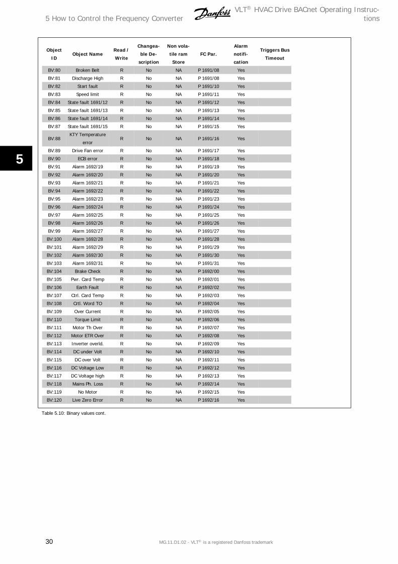
BV:80 Broken Belt R No NA P 1691/08 Yes
BV:81 Discharge High R No NA P 1691/08 Yes
BV:82 Start fault R No NA P 1691/10 Yes
BV:83 Speed limit R No NA P 1691/11 Yes
BV:84 State fault 1691/12 R No NA P 1691/12 Yes
BV:85 State fault 1691/13 R No NA P 1691/13 Yes
BV:86 State fault 1691/14 R No NA P 1691/14 Yes
BV:87 State fault 1691/15 R No NA P 1691/15 Yes
BV:88KTY Temperature
errorR No NA P 1691/16 Yes
BV:89 Drive Fan error R No NA P 1691/17 Yes
BV:90 ECB error R No NA P 1691/18 Yes
BV:91 Alarm 1692/19 R No NA P 1691/19 Yes
BV:92 Alarm 1692/20 R No NA P 1691/20 Yes
BV:93 Alarm 1692/21 R No NA P 1691/21 Yes
BV:94 Alarm 1692/22 R No NA P 1691/22 Yes
BV:95 Alarm 1692/23 R No NA P 1691/23 Yes
BV:96 Alarm 1692/24 R No NA P 1691/24 Yes
BV:97 Alarm 1692/25 R No NA P 1691/25 Yes
BV:98 Alarm 1692/26 R No NA P 1691/26 Yes
BV:99 Alarm 1692/27 R No NA P 1691/27 Yes
BV:100 Alarm 1692/28 R No NA P 1691/28 Yes
BV:101 Alarm 1692/29 R No NA P 1691/29 Yes
BV:102 Alarm 1692/30 R No NA P 1691/30 Yes
BV:103 Alarm 1692/31 R No NA P 1691/31 Yes
BV:104 Brake Check R No NA P 1692/00 Yes
BV:105 Pwr. Card Temp R No NA P 1692/01 Yes
BV:106 Earth Fault R No NA P 1692/02 Yes
BV:107 Ctrl. Card Temp R No NA P 1692/03 Yes
BV:108 Crtl. Word TO R No NA P 1692/04 Yes
BV:109 Over Current R No NA P 1692/05 Yes
BV:110 Torque Limit R No NA P 1692/06 Yes
BV:111 Motor Th Over R No NA P 1692/07 Yes
BV:112 Motor ETR Over R No NA P 1692/08 Yes
BV:113 Inverter overld. R No NA P 1692/09 Yes
BV:114 DC under Volt R No NA P 1692/10 Yes
BV:115 DC over Volt R No NA P 1692/11 Yes
BV:116 DC Voltage Low R No NA P 1692/12 Yes
BV:117 DC Voltage high R No NA P 1692/13 Yes
BV:118 Mains Ph. Loss R No NA P 1692/14 Yes
BV:119 No Motor R No NA P 1692/15 Yes
BV:120 Live Zero Error R No NA P 1692/16 Yes
Table 5.10: Binary values cont.
5 How to Control the Frequency ConverterVLT® HVAC Drive BACnet Operating Instruc-
tions
30 MG.11.D1.02 - VLT® is a registered Danfoss trademark
5
Object
IDObject Name
Read /
Write
Changea-
ble De-
scription
Non vola-
tile ram
Store
FC Par.
Alarm
notifi-
cation
Triggers Bus
Timeout
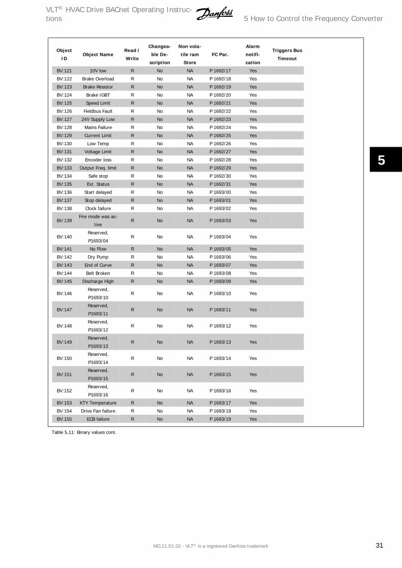
BV:121 10V low R No NA P 1692/17 Yes
BV:122 Brake Overload R No NA P 1692/18 Yes
BV:123 Brake Resistor R No NA P 1692/19 Yes
BV:124 Brake IGBT R No NA P 1692/20 Yes
BV:125 Speed Limit R No NA P 1692/21 Yes
BV:126 Fieldbus Fault R No NA P 1692/22 Yes
BV:127 24V Supply Low R No NA P 1692/23 Yes
BV:128 Mains Failure R No NA P 1692/24 Yes
BV:129 Current Limit R No NA P 1692/25 Yes
BV:130 Low Temp R No NA P 1692/26 Yes
BV:131 Voltage Limit R No NA P 1692/27 Yes
BV:132 Encoder loss R No NA P 1692/28 Yes
BV:133 Output Freq. limit R No NA P 1692/29 Yes
BV:134 Safe stop R No NA P 1692/30 Yes
BV:135 Ext. Status R No NA P 1692/31 Yes
BV:136 Start delayed R No NA P 1693/00 Yes
BV:137 Stop delayed R No NA P 1693/01 Yes
BV:138 Clock failure R No NA P 1693/02 Yes
BV:139Fire mode was ac-
tiveR No NA P 1693/03 Yes
BV:140Reserved,
P1693/04R No NA P 1693/04 Yes
BV:141 No Flow R No NA P 1693/05 Yes
BV:142 Dry Pump R No NA P 1693/06 Yes
BV:143 End of Curve R No NA P 1693/07 Yes
BV:144 Belt Broken R No NA P 1693/08 Yes
BV:145 Discharge High R No NA P 1693/09 Yes
BV:146Reserved,
P1693/10R No NA P 1693/10 Yes
BV:147Reserved,
P1693/11R No NA P 1693/11 Yes
BV:148Reserved,
P1693/12R No NA P 1693/12 Yes
BV:149Reserved,
P1693/13R No NA P 1693/13 Yes
BV:150Reserved,
P1693/14R No NA P 1693/14 Yes
BV:151Reserved,
P1693/15R No NA P 1693/15 Yes
BV:152Reserved,
P1693/16R No NA P 1693/16 Yes
BV:153 KTY Temperature R No NA P 1693/17 Yes
BV:154 Drive Fan failure R No NA P 1693/18 Yes
BV:155 ECB failure R No NA P 1693/19 Yes
Table 5.11: Binary values cont.
VLT® HVAC Drive BACnet Operating Instruc-tions 5 How to Control the Frequency Converter
MG.11.D1.02 - VLT® is a registered Danfoss trademark 31
5
Object
IDObject Name
Read /
Write
Changea-
ble De-
scription
Non vola-
tile ram
Store
FC Par.
Alarm
notifi-
cation
Triggers Bus
Timeout
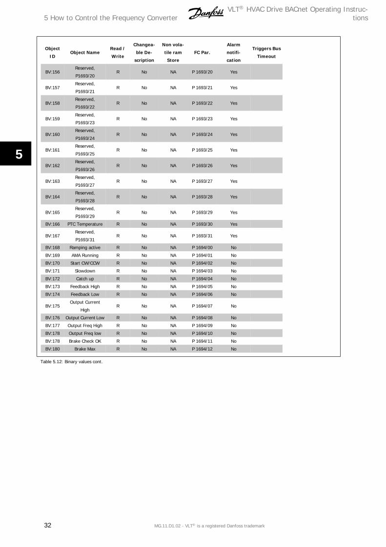
BV:156Reserved,
P1693/20R No NA P 1693/20 Yes
BV:157Reserved,
P1693/21R No NA P 1693/21 Yes
BV:158Reserved,
P1693/22R No NA P 1693/22 Yes
BV:159Reserved,
P1693/23R No NA P 1693/23 Yes
BV:160Reserved,
P1693/24R No NA P 1693/24 Yes
BV:161Reserved,
P1693/25R No NA P 1693/25 Yes
BV:162Reserved,
P1693/26R No NA P 1693/26 Yes
BV:163Reserved,
P1693/27R No NA P 1693/27 Yes
BV:164Reserved,
P1693/28R No NA P 1693/28 Yes
BV:165Reserved,
P1693/29R No NA P 1693/29 Yes
BV:166 PTC Temperature R No NA P 1693/30 Yes
BV:167Reserved,
P1693/31R No NA P 1693/31 Yes
BV:168 Ramping active R No NA P 1694/00 No
BV:169 AMA Running R No NA P 1694/01 No
BV:170 Start CW/CCW R No NA P 1694/02 No
BV:171 Slowdown R No NA P 1694/03 No
BV:172 Catch up R No NA P 1694/04 No
BV:173 Feedback High R No NA P 1694/05 No
BV:174 Feedback Low R No NA P 1694/06 No
BV:175Output Current
HighR No NA P 1694/07 No
BV:176 Output Current Low R No NA P 1694/08 No
BV:177 Output Freq High R No NA P 1694/09 No
BV:178 Output Freq low R No NA P 1694/10 No
BV:178 Brake Check OK R No NA P 1694/11 No
BV:180 Brake Max R No NA P 1694/12 No
Table 5.12: Binary values cont.
5 How to Control the Frequency ConverterVLT® HVAC Drive BACnet Operating Instruc-
tions
32 MG.11.D1.02 - VLT® is a registered Danfoss trademark
5

Object
IDObject Name
Read /
Write
Changea-
ble De-
scription
Non vola-
tile ram
Store
FC Par.
Alarm
notifi-
cation
Triggers Bus
Timeout
BV:181 Braking R No NA P 1694/13 No
BV:182 Out of Speed range R No NA P 1694/14 No
BV:183 OVC Active R No NA P 1694/15 No
BV:184 AC Brake R No NA P 1694/16 No
BV:185 Password Timelock R No NA P 1694/17 No
BV:186 Password status R No NA P 1694/18 No
BV:187 Reference high R No NA P 1694/19 No
BV:188 Reference low R No NA P 1694/20 No
BV:189 Reference site R No NA P 1694/21 No
BV:190Reserved,
P1694/22R No NA P 1694/22 No
BV:191Reserved,
P1694/23R No NA P 1694/23 No
BV:192Reserved,
P1694/24R No NA P 1694/24 No
BV:193Reserved,
P1694/25R No NA P 1694/25 No
BV:194Reserved,
P1694/26R No NA P 1694/26 No
BV:195Reserved,
P1694/27R No NA P 1694/27 No
BV:196Reserved,
P1694/28R No NA P 1694/28 No
BV:197Reserved,
P1694/29R No NA P 1694/29 No
BV:198Reserved,
P1694/30R No NA P 1694/30 No
BV:199Reserved,
P1694/31R No NA P 1694/31 No
Table 5.13: Binary values cont.
5.2.3 Multi-state Input- and Output Objects
Multi-state Variable
Object
IdObject Name
Read/
Write
Changea-
ble De-
scription
Non volatile
ram StoreFC Par.
Alarm notifi-
cation
Triggers Bus
Timeout
MSV:0 SL Controller State R No Non P16-38 No No
MSV:1 Setup selection W/R No NonBit13&14 in
CTWNo No
Mailbox variable
Object
IdObject Name
Read/
Write
Changea-
ble De-
scription
Non volatile
ram StoreFC Par.
Alarm notifi-
cation
Triggers Bus
Timeout
MBV:0 Mailbox Write W/R No Non
PCV part of
the send FC
telegram
No No
MBV:1 Mailbox Read R No Non
PCV part of
the receive
FC telegram
No No
VLT® HVAC Drive BACnet Operating Instruc-tions 5 How to Control the Frequency Converter
MG.11.D1.02 - VLT® is a registered Danfoss trademark 33
5

5.2.4 Real Time Clock Variable
The frequency converter has a built-in real-time clock. The standard real-time clock has no battery back-up function, which will lead to a time stop if the
FC is unpowered. Some BACnet Master's can be programmed to send out the date and time as a Broadcast Telegram on a regular basis. The BACnet will
update the real-time clock of the FC if it receives this type of telegram: “Telegram”.
5.3 Frequency Converter Feedback to NetworkThe BACnet option provides several output variables (nvo’s) to the network, containing important frequency converter-, motor- and I/O feedback data.
The BACnet option transmits bound network variables only and sends feedback data when there is a change in value.
Influence of the digital input terminals upon the FC Control Mode, parameters 8-50 to 8-56.
The influence of the digital input terminals upon control of the frequency converter can be programmed in parameters 8-50 to 8-56.
NB!
Par. 8-01 Control Site overrules the settings in parameters 8-50 to 8-56 and Terminal 37, Safe Stop overrules any parameter.
Each of the digital input signals can be programmed to logic AND, logic OR, or to have no relation to the corresponding bit in the control word. In this
way a specific control command i.e. stop / coast, can be initiated by the fieldbus only, fieldbus AND Digital Input, or Ether Fieldbus OR Digital input
terminal.
In order to control the frequency converter via BACnet, par. 8-50 Coasting Select must be set to either Bus [1], or to Logic AND [2]
and par. 8-01 Control Site must be set to Digital and ctrl. word [0] or Controlword only [2].
More detailed information and examples of logical relationship options are provided in the Troubleshooting chapter.
5 How to Control the Frequency ConverterVLT® HVAC Drive BACnet Operating Instruc-
tions
34 MG.11.D1.02 - VLT® is a registered Danfoss trademark
5
The
follo
win
g ta
ble
sum
mar
ises
th
e O
bjec
t Ty
pes
and
Pro
pert
ies
supp
orte
d:
Pro
pert
yD
evic
eB
inar
y in
put
Bin
ary
out-
put
Bin
ary
valu
eA
nal
og in
put
An
alog
out
-pu
tA
nal
og v
alu
eM
ult
ista
geva
lue
File
Even
t n
otif
i-ca
tion
cla
ssO
bjec
t id
entif
ier
XX
XX
XX
XX
XX
Obj
ect
Nam
eX
XX
XX
XX
XX
XO
bjec
t Ty
peX
XX
XX
XX
XX
XSy
stem
Sta
tus
X
Vend
or N
ame
X
Vend
or I
dent
ifier
X
Mod
el N
ame
X
Firm
war
e Rev
isio
nX
Ap
pl. S
oftw
are
Re-
visi
onX
Loca
tion
X
Des
crip
tion
XX
XX
XX
XX
XX
Prot
ocol
Ver
sion
X
Prot
ocol
Rev
isio
nX
Se
rvic
es S
uppo
rted
X
Obj
ect
Type
s Su
p-po
rted
X
Obj
ect
List
X
Max
. APD
U L
engt
hX
Se
gmen
tatio
n Su
p-po
rtX
Loca
l Tim
eX
Lo
cal D
ate
X
APD
U T
imeo
utX
N
umbe
r AP
DU
Re-
trie
sX
Max
Mas
ter
X
Max
Inf
o Fr
ames
X
Dev
ice
Addr
ess
Bind
ing
X
Dat
abas
e Rev
isio
nX
Pr
esen
t Va
lue
X
XX
XX
X
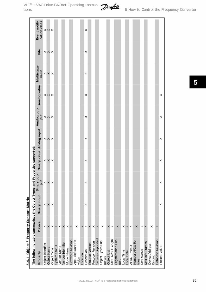
5.4.
1O
bjec
t /
Pro
pert
y Su
ppor
t M
atri
x
VLT® HVAC Drive BACnet Operating Instruc-tions 5 How to Control the Frequency Converter
MG.11.D1.02 - VLT® is a registered Danfoss trademark 35
5

Obj
ect
/ P
rope
rty
Supp
ort
Mat
rix,
con
tin
ued
..
Pro
pert
yD
evic
eB
inar
y in
put
Bin
ary
out-
put
Bin
ary
valu
eA
nal
og in
put
An
alog
out
-pu
tA
nal
og v
alu
eM
ult
ista
geva
lue
File
Even
t n
otif
i-ca
tion
cla
ssSt
atus
Fla
gs
XX
XX
XX
Ev
ent
Stat
e
XX
XX
XX
Rel
iabi
lity
X
XX
XX
X
Out
-of-
Serv
ice
X
XX
XX
X
Num
ber
of S
tate
s
X
St
ate
Text
X
Uni
ts
X
XX
Ti
me
Del
ay
X
X
N
otifi
catio
n Cl
ass
X
X
Hig
h Li
mit
X
X
Low
Lim
it
X
X
D
eadb
and
X
X
Lim
it En
able
X
X
Even
t En
able
X
X
Acke
d Tr
ansi
tions
X
X
Not
ify T
ype
X
X
Even
t Ti
me
Stam
p
X
X
Pr
iorit
y Ar
ray
XX*
X
??X
Prio
rity
X
ACk
Req
uire
d
XRec
ipie
nt L
ist
X
# o
f N
otifi
catio
nCl
ass
X
Rel
inqu
ish
Def
ault
XX*
X
??X
Pola
rity
X
X
Activ
e Te
xt
XX
X
Inac
tive
Text
X
XX
File
typ
e
X
Fi
le s
ize
X
Mod
ifica
tion
Dat
e
X
Ar
chiv
e
X
Rea
d O
nly
X
File
Acc
ess
Met
hod
X
*For
com
man
dabl
e va
lues
onl
y
5 How to Control the Frequency ConverterVLT® HVAC Drive BACnet Operating Instruc-
tions
36 MG.11.D1.02 - VLT® is a registered Danfoss trademark
5
6 Parameters
6.1 Parameter Overview
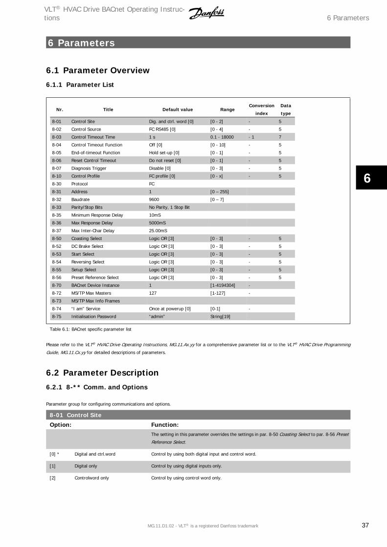
6.1.1 Parameter List
Nr. Title Default value RangeConversion
index
Data
type
8-01 Control Site Dig. and ctrl. word [0] [0 - 2] - 5
8-02 Control Source FC RS485 [0] [0 - 4] - 5
8-03 Control Timeout Time 1 s 0.1 - 18000 - 1 7
8-04 Control Timeout Function Off [0] [0 - 10] - 5
8-05 End-of-timeout Function Hold set-up [0] [0 - 1] - 5
8-06 Reset Control Timeout Do not reset [0] [0 - 1] - 5
8-07 Diagnosis Trigger Disable [0] [0 - 3] - 5
8-10 Control Profile FC profile [0] [0 - x] - 5
8-30 Protocol FC
8-31 Address 1 [0 – 255]
8-32 Baudrate 9600 [0 – 7]
8-33 Parity/Stop Bits No Parity, 1 Stop Bit
8-35 Minimum Response Delay 10mS
8-36 Max Response Delay 5000mS
8-37 Max Inter-Char Delay 25.00mS
8-50 Coasting Select Logic OR [3] [0 - 3] - 5
8-52 DC Brake Select Logic OR [3] [0 - 3] - 5
8-53 Start Select Logic OR [3] [0 - 3] - 5
8-54 Reversing Select Logic OR [3] [0 - 3] - 5
8-55 Setup Select Logic OR [3] [0 - 3] - 5
8-56 Preset Reference Select Logic OR [3] [0 - 3] - 5
8-70 BACnet Device Instance 1 [1-4194304] -
8-72 MS/TP Max Masters 127 [1-127] -
8-73 MS/TP Max Info Frames
8-74 “I am” Service Once at powerup [0] [0-1] -
8-75 Initialisation Password “admin” String[19]
Table 6.1: BACnet specific parameter list
Please refer to the VLT® HVAC Drive Operating Instructions, MG.11.Ax.yy for a comprehensive parameter list or to the VLT® HVAC Drive Programming
Guide, MG.11.Cx.yy for detailed descriptions of parameters.
6.2 Parameter Description
6.2.1 8-** Comm. and Options
Parameter group for configuring communications and options.
8-01 Control Site
Option: Function:The setting in this parameter overrides the settings in par. 8-50 Coasting Select to par. 8-56 Preset
Reference Select.
[0] * Digital and ctrl.word Control by using both digital input and control word.
[1] Digital only Control by using digital inputs only.
[2] Controlword only Control by using control word only.
VLT® HVAC Drive BACnet Operating Instruc-tions 6 Parameters
MG.11.D1.02 - VLT® is a registered Danfoss trademark 37
6

8-02 Control Source
Option: Function:Select the source of the control word: one of two serial interfaces or four installed options. During
initial power-up, the frequency converter automatically sets this parameter to Option A [3] if it
detects a valid fieldbus option installed in slot A. If the option is removed, the frequency converter
detects a change in the configuration, sets par. 8-02 Control Source back to default setting FC
Port, and the frequency converter then trips. If an option is installed after initial power-up, the
setting of par. 8-02 Control Source will not change but the frequency converter will trip and display:
Alarm 67 Option Changed.
[0] None
[1] FC Port
[2] USB Port
[3] * Option A
[4] Option B
[5] Option C0
[6] Option C1
[30] External Can
NB!
This parameter cannot be adjusted while the motor is running.
8-03 Control Timeout Time
Range: Function:60.0 s* [1.0 - 18000.0 s] Enter the maximum time expected to pass between the reception of two consecutive telegrams. If
this time is exceeded, it indicates that the serial communication has stopped. The function selected
in par. 8-04 Control Timeout Function Control Time-out Function will then be carried out.
In LonWorks the following variables will trigger the Control Word Time parameter:
nviStartStop
nviReset Fault
nviControlWord
nviDrvSpeedStpt
nviRefPcnt
nviRefHz
6 ParametersVLT® HVAC Drive BACnet Operating Instruc-
tions
38 MG.11.D1.02 - VLT® is a registered Danfoss trademark
6
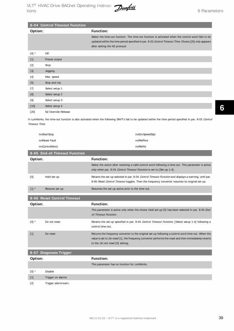
8-04 Control Timeout Function
Option: Function:Select the time-out function. The time-out function is activated when the control word fails to be
updated within the time period specified in par. 8-03 Control Timeout Time. Choice [20] only appears
after setting the N2 protocol.
[0] * Off
[1] Freeze output
[2] Stop
[3] Jogging
[4] Max. speed
[5] Stop and trip
[7] Select setup 1
[8] Select setup 2
[9] Select setup 3
[10] Select setup 4
[20] N2 Override Release
In LonWorks, the time-out function is also activated when the following SNVT's fail to be updated within the time period specified in par. 8-03 Control
Timeout Time:
nviStartStop
nviReset Fault
nviControlWord
nviDrvSpeedStpt
nviRefPcnt
nviRefHz
8-05 End-of-Timeout Function
Option: Function:Select the action after receiving a valid control word following a time-out. This parameter is active
only when par. 8-04 Control Timeout Function is set to [Set-up 1-4].
[0] Hold set-up Retains the set-up selected in par. 8-04 Control Timeout Function and displays a warning, until par.
8-06 Reset Control Timeout toggles. Then the frequency converter resumes its original set-up.
[1] * Resume set-up Resumes the set-up active prior to the time-out.
8-06 Reset Control Timeout
Option: Function:This parameter is active only when the choice Hold set-up [0] has been selected in par. 8-05 End-
of-Timeout Function .
[0] * Do not reset Retains the set-up specified in par. 8-04 Control Timeout Function, [Select setup 1-4] following a
control time-out.
[1] Do reset Returns the frequency converter to the original set-up following a control word time-out. When the
value is set to Do reset [1], the frequency converter performs the reset and then immediately reverts
to the Do not reset [0] setting.
8-07 Diagnosis Trigger
Option: Function:This parameter has no function for LonWorks.
[0] * Disable
[1] Trigger on alarms
[2] Trigger alarm/warn.
VLT® HVAC Drive BACnet Operating Instruc-tions 6 Parameters
MG.11.D1.02 - VLT® is a registered Danfoss trademark 39
6
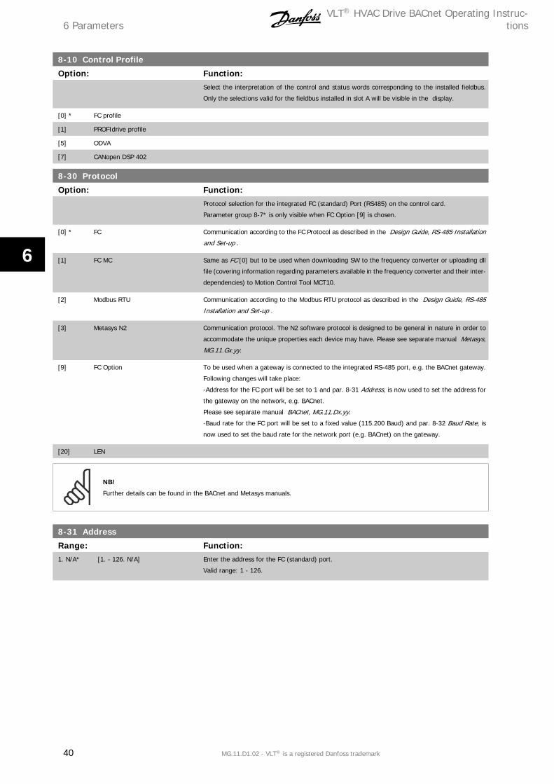
8-10 Control Profile
Option: Function:Select the interpretation of the control and status words corresponding to the installed fieldbus.
Only the selections valid for the fieldbus installed in slot A will be visible in the display.
[0] * FC profile
[1] PROFIdrive profile
[5] ODVA
[7] CANopen DSP 402
8-30 Protocol
Option: Function:Protocol selection for the integrated FC (standard) Port (RS485) on the control card.
Parameter group 8-7* is only visible when FC Option [9] is chosen.
[0] * FC Communication according to the FC Protocol as described in the Design Guide, RS-485 Installation
and Set-up .
[1] FC MC Same as FC [0] but to be used when downloading SW to the frequency converter or uploading dll
file (covering information regarding parameters available in the frequency converter and their inter-
dependencies) to Motion Control Tool MCT10.
[2] Modbus RTU Communication according to the Modbus RTU protocol as described in the Design Guide, RS-485
Installation and Set-up .
[3] Metasys N2 Communication protocol. The N2 software protocol is designed to be general in nature in order to
accommodate the unique properties each device may have. Please see separate manual Metasys,
MG.11.Gx.yy.
[9] FC Option To be used when a gateway is connected to the integrated RS-485 port, e.g. the BACnet gateway.
Following changes will take place:
-Address for the FC port will be set to 1 and par. 8-31 Address, is now used to set the address for
the gateway on the network, e.g. BACnet.
Please see separate manual BACnet, MG.11.Dx.yy.
-Baud rate for the FC port will be set to a fixed value (115.200 Baud) and par. 8-32 Baud Rate, is
now used to set the baud rate for the network port (e.g. BACnet) on the gateway.
[20] LEN
NB!
Further details can be found in the BACnet and Metasys manuals.
8-31 Address
Range: Function:1. N/A* [1. - 126. N/A] Enter the address for the FC (standard) port.
Valid range: 1 - 126.
6 ParametersVLT® HVAC Drive BACnet Operating Instruc-
tions
40 MG.11.D1.02 - VLT® is a registered Danfoss trademark
6

8-32 Baud Rate
Option: Function:Baud rate selection depends on Protocol selection in par. 8-30 Protocol.
[0] 2400 Baud
[1] 4800 Baud
[2] * 9600 Baud
[3] 19200 Baud
[4] 38400 Baud
[5] 57600 Baud
[6] 76800 Baud
[7] 115200 Baud
Default refers to the FC Protocol.
8-33 Parity / Stop Bits
Option: Function:Parity and Stop Bits for the protocol par. 8-30 Protocol using the FC Port. For some of the protocols,
not all options will be visible. Default depends on the protocol selected.
[0] * Even Parity, 1 Stop Bit
[1] Odd Parity, 1 Stop Bit
[2] No Parity, 1 Stop Bit
[3] No Parity, 2 Stop Bits
8-35 Minimum Response Delay
Range: Function:10. ms* [5. - 10000. ms] Specify the minimum delay time between receiving a request and transmitting a response. This is
used for overcoming modem turnaround delays.
8-36 Maximum Response Delay
Range: Function:10001. ms* [11. - 10001. ms] Specify the maximum permissible delay time between transmitting a request and receiving a re-
sponse. Exceeding this delay time will cause control word time-out.
8-37 Maximum Inter-Char Delay
Range: Function:25.00 ms* [0.00 - 35.00 ms] Specify the maximum permissible time interval between receipt of two bytes. This parameter acti-
vates time-out if transmission is interrupted.
8-50 Coasting Select
Option: Function:Select control of the coasting function via the terminals (digital input) and/or via the bus.
[0] Digital input
[1] Bus Activates Start command via the serial communication port or fieldbus option.
[2] Logic AND Activates Start command via the fieldbus/serial communication port, AND additionally via one of the
digital inputs.
[3] * Logic OR Activates Start command via the fieldbus/serial communication port OR via one of the digital inputs.
VLT® HVAC Drive BACnet Operating Instruc-tions 6 Parameters
MG.11.D1.02 - VLT® is a registered Danfoss trademark 41
6
NB!
This parameter is active only when par. 8-01 Control Site is set to [0] Digital and control word.
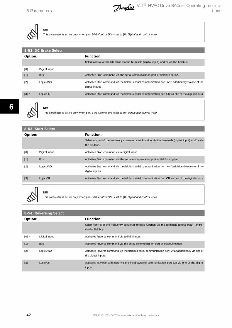
8-52 DC Brake Select
Option: Function:Select control of the DC brake via the terminals (digital input) and/or via the fieldbus.
[0] Digital input
[1] Bus Activates Start command via the serial communication port or fieldbus option.
[2] Logic AND Activates Start command via the fieldbus/serial communication port, AND additionally via one of the
digital inputs.
[3] * Logic OR Activates Start command via the fieldbus/serial communication port OR via one of the digital inputs.
NB!
This parameter is active only when par. 8-01 Control Site is set to [0] Digital and control word.
8-53 Start Select
Option: Function:Select control of the frequency converter start function via the terminals (digital input) and/or via
the fieldbus.
[0] Digital input Activates Start command via a digital input.
[1] Bus Activates Start command via the serial communication port or fieldbus option.
[2] Logic AND Activates Start command via the fieldbus/serial communication port, AND additionally via one of the
digital inputs.
[3] * Logic OR Activates Start command via the fieldbus/serial communication port OR via one of the digital inputs.
NB!
This parameter is active only when par. 8-01 Control Site is set to [0] Digital and control word.
8-54 Reversing Select
Option: Function:Select control of the frequency converter reverse function via the terminals (digital input) and/or
via the fieldbus.
[0] * Digital input Activates Reverse command via a digital input.
[1] Bus Activates Reverse command via the serial communication port or fieldbus option.
[2] Logic AND Activates Reverse command via the fieldbus/serial communication port, AND additionally via one of
the digital inputs.
[3] Logic OR Activates Reverse command via the fieldbus/serial communication port OR via one of the digital
inputs.
6 ParametersVLT® HVAC Drive BACnet Operating Instruc-
tions
42 MG.11.D1.02 - VLT® is a registered Danfoss trademark
6

NB!
This parameter is active only when par. 8-01 Control Site is set to [0] Digital and control word.
8-55 Set-up Select
Option: Function:Select control of the frequency converter set-up selection via the terminals (digital input) and/or via
the fieldbus.
[0] Digital input Activates the set-up selection via a digital input.
[1] Bus Activates the set-up selection via the serial communication port or fieldbus option.
[2] Logic AND Activates the set-up selection via the fieldbus/serial communication port, AND additionally via one
of the digital inputs.
[3] * Logic OR Activate the set-up selection via the fieldbus/serial communication port OR via one of the digital
inputs.
NB!
This parameter is active only when par. 8-01 Control Site is set to [0] Digital and control word.
8-56 Preset Reference Select
Option: Function:Select control of the frequency converter Preset Reference selection via the terminals (digital input)
and/or via the fieldbus.
[0] Digital input Activates Preset Reference selection via a digital input.
[1] Bus Activates Preset Reference selection via the serial communication port or fieldbus option.
[2] Logic AND Activates Preset Reference selection via the fieldbus/serial communication port, AND additionally
via one of the digital inputs.
[3] * Logic OR Activates the Preset Reference selection via the fieldbus/serial communication port OR via one of
the digital inputs.
NB!
This parameter is active only when par. 8-01 Control Site is set to [0] Digital and control word.
8-70 BACnet Device Instance
Range: Function:1 N/A* [0 - 4194304 N/A] Enter a unique ID number for the BACnet device.
NB!
This parameter is active only when par. 8-30 Protocol is set to [9] FC Option.
8-72 MS/TP Max Masters
Range: Function:127 N/A* [0 - 127 N/A] Define the address of the master which holds the highest address in this network. Decreasing this
value optimises polling for the token.
VLT® HVAC Drive BACnet Operating Instruc-tions 6 Parameters
MG.11.D1.02 - VLT® is a registered Danfoss trademark 43
6

NB!
This parameter is active only when par. 8-30 Protocol is set to [9] FC Option.
8-73 MS/TP Max Info Frames
Range: Function:1 N/A* [1 - 65534 N/A] Define how many info/data frames the device is allowed to send while holding the token.
NB!
This parameter is active only when par. 8-30 Protocol is set to [9] FC Option.
8-74 "I-Am" Service
Option: Function:[0] * Send at power-up
[1] Continuously Choose whether the device should send the "I-Am" service message only at power-up or continu-
ously with an interval of approx. 1 min.
NB!
This parameter is active only when par. 8-30 Protocol is set to [9] FC Option.
8-75 Initialisation Password
Range: Function:0 N/A* [0 - 0 N/A] Enter the password needed for execution of Drive Re-initialisation from BACnet.
NB!
This parameter is active only when par. 8-30 Protocol is set to [9] FC Option.
6 ParametersVLT® HVAC Drive BACnet Operating Instruc-
tions
44 MG.11.D1.02 - VLT® is a registered Danfoss trademark
6
7 Troubleshooting
7.1 Alarm-, Warning and Extended Status Word
7.1.1 Alarm and warning messages
General
There is a clear distinction between alarms and warnings. In the event of an alarm, the frequency converter will enter a fault condition. After the cause
for the alarm has been cleared, the master must acknowledge the alarm message in order to start operation of the frequency converter again. A warning,
on the other hand, may appear when a warning condition arises, then disappear when conditions return to normal without interfering with the process.
Alarm Word and Warning Word are shown on the display in Hex format. If there is more than one warning or alarm, a sum of all warnings or alarms will
be shown. Warning Word and Alarm Word are displayed in par. 16-90 to 16-95. For more information on the individual alarms and warnings, please refer
to: VLT® HVAC Drive Design Guide.
Warnings
All warnings within the frequency converter are represented by a single bit within a Warning Word. A Warning Word is always an action parameter. Bit
status FALSE [0] means no warning, while bit status TRUE [1] means warning. Each bit status has a corresponding text string message. In addition to
the Warning Word message the master will also be notified via a change to bit 7 in the status word.
Alarms
Following an alarm message the frequency converter will enter a fault condition. Only after the fault has been rectified and the master has acknowledged
the alarm message by setting bit 3 in the Control Word, can the FC resume operation. All alarms within the FC are represented by a single bit within an
Alarm Word. An Alarm Word is always an action parameter. Bit status FALSE [0] means no alarm, while bit status TRUE [1] means alarm.
VLT® HVAC Drive BACnet Operating Instruc-tions 7 Troubleshooting
MG.11.D1.02 - VLT® is a registered Danfoss trademark 45
7
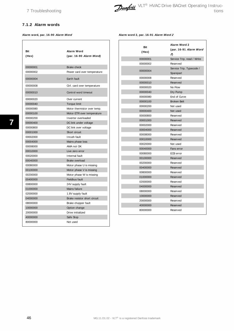
7.1.2 Alarm words
Alarm word, par. 16-90 Alarm Word
Bit
(Hex)
Alarm Word
(par. 16-90 Alarm Word)
00000001 Brake check
00000002 Power card over temperature
00000004 Earth fault
00000008 Ctrl. card over temperature
00000010 Control word timeout
00000020 Over current
00000040 Torque limit
00000080 Motor thermistor over temp.
00000100 Motor ETR over temperature
00000200 Inverter overloaded
00000400 DC link under voltage
00000800 DC link over voltage
00001000 Short circuit
00002000 Inrush fault
00004000 Mains phase loss
00008000 AMA not OK
00010000 Live zero error
00020000 Internal fault
00040000 Brake overload
00080000 Motor phase U is missing
00100000 Motor phase V is missing
00200000 Motor phase W is missing
00400000 Fieldbus fault
00800000 24V supply fault
01000000 Mains failure
02000000 1.8V supply fault
04000000 Brake resistor short circuit
08000000 Brake chopper fault
10000000 Option change
20000000 Drive initialized
40000000 Safe Stop
80000000 Not used
Alarm word 2, par. 16-91 Alarm Word 2
Bit
(Hex)
Alarm Word 2
(par. 16-91 Alarm Word
2)
00000001 Service Trip, read / Write
00000002 Reserved
00000004Service Trip, Typecode /
Sparepart
00000008 Reserved
00000010 Reserved
00000020 No Flow
00000040 Dry Pump
00000080 End of Curve
00000100 Broken Belt
00000200 Not used
00000400 Not used
00000800 Reserved
00001000 Reserved
00002000 Reserved
00004000 Reserved
00008000 Reserved
00010000 Reserved
00020000 Not used
00040000 Fans error
00080000 ECB error
00100000 Reserved
00200000 Reserved
00400000 Reserved
00800000 Reserved
01000000 Reserved
02000000 Reserved
04000000 Reserved
08000000 Reserved
10000000 Reserved
20000000 Reserved
40000000 Reserved
80000000 Reserved
7 TroubleshootingVLT® HVAC Drive BACnet Operating Instruc-
tions
46 MG.11.D1.02 - VLT® is a registered Danfoss trademark
7
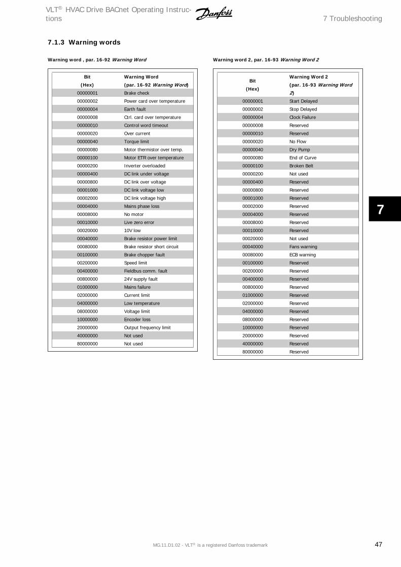
7.1.3 Warning words
Warning word , par. 16-92 Warning Word
Bit
(Hex)
Warning Word
(par. 16-92 Warning Word)
00000001 Brake check
00000002 Power card over temperature
00000004 Earth fault
00000008 Ctrl. card over temperature
00000010 Control word timeout
00000020 Over current
00000040 Torque limit
00000080 Motor thermistor over temp.
00000100 Motor ETR over temperature
00000200 Inverter overloaded
00000400 DC link under voltage
00000800 DC link over voltage
00001000 DC link voltage low
00002000 DC link voltage high
00004000 Mains phase loss
00008000 No motor
00010000 Live zero error
00020000 10V low
00040000 Brake resistor power limit
00080000 Brake resistor short circuit
00100000 Brake chopper fault
00200000 Speed limit
00400000 Fieldbus comm. fault
00800000 24V supply fault
01000000 Mains failure
02000000 Current limit
04000000 Low temperature
08000000 Voltage limit
10000000 Encoder loss
20000000 Output frequency limit
40000000 Not used
80000000 Not used
Warning word 2, par. 16-93 Warning Word 2
Bit
(Hex)
Warning Word 2
(par. 16-93 Warning Word
2)
00000001 Start Delayed
00000002 Stop Delayed
00000004 Clock Failure
00000008 Reserved
00000010 Reserved
00000020 No Flow
00000040 Dry Pump
00000080 End of Curve
00000100 Broken Belt
00000200 Not used
00000400 Reserved
00000800 Reserved
00001000 Reserved
00002000 Reserved
00004000 Reserved
00008000 Reserved
00010000 Reserved
00020000 Not used
00040000 Fans warning
00080000 ECB warning
00100000 Reserved
00200000 Reserved
00400000 Reserved
00800000 Reserved
01000000 Reserved
02000000 Reserved
04000000 Reserved
08000000 Reserved
10000000 Reserved
20000000 Reserved
40000000 Reserved
80000000 Reserved
VLT® HVAC Drive BACnet Operating Instruc-tions 7 Troubleshooting
MG.11.D1.02 - VLT® is a registered Danfoss trademark 47
7
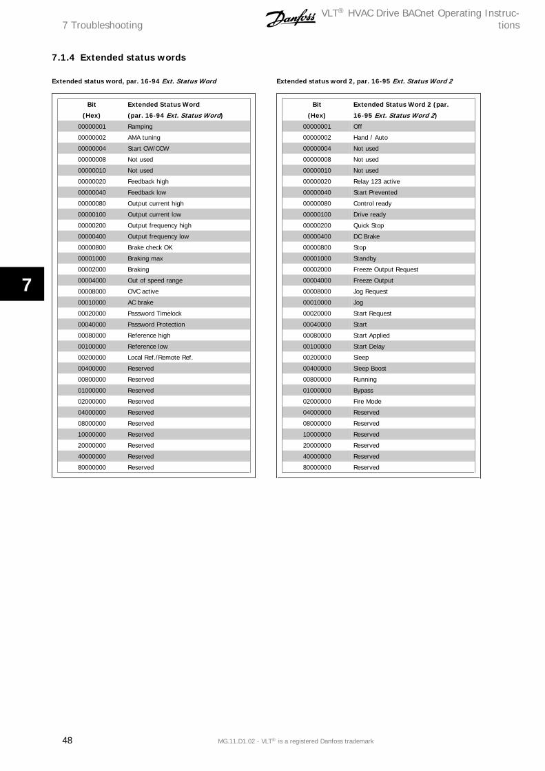
7.1.4 Extended status words
Extended status word, par. 16-94 Ext. Status Word
Bit
(Hex)
Extended Status Word
(par. 16-94 Ext. Status Word)
00000001 Ramping
00000002 AMA tuning
00000004 Start CW/CCW
00000008 Not used
00000010 Not used
00000020 Feedback high
00000040 Feedback low
00000080 Output current high
00000100 Output current low
00000200 Output frequency high
00000400 Output frequency low
00000800 Brake check OK
00001000 Braking max
00002000 Braking
00004000 Out of speed range
00008000 OVC active
00010000 AC brake
00020000 Password Timelock
00040000 Password Protection
00080000 Reference high
00100000 Reference low
00200000 Local Ref./Remote Ref.
00400000 Reserved
00800000 Reserved
01000000 Reserved
02000000 Reserved
04000000 Reserved
08000000 Reserved
10000000 Reserved
20000000 Reserved
40000000 Reserved
80000000 Reserved
Extended status word 2, par. 16-95 Ext. Status Word 2
Bit
(Hex)
Extended Status Word 2 (par.
16-95 Ext. Status Word 2)
00000001 Off
00000002 Hand / Auto
00000004 Not used
00000008 Not used
00000010 Not used
00000020 Relay 123 active
00000040 Start Prevented
00000080 Control ready
00000100 Drive ready
00000200 Quick Stop
00000400 DC Brake
00000800 Stop
00001000 Standby
00002000 Freeze Output Request
00004000 Freeze Output
00008000 Jog Request
00010000 Jog
00020000 Start Request
00040000 Start
00080000 Start Applied
00100000 Start Delay
00200000 Sleep
00400000 Sleep Boost
00800000 Running
01000000 Bypass
02000000 Fire Mode
04000000 Reserved
08000000 Reserved
10000000 Reserved
20000000 Reserved
40000000 Reserved
80000000 Reserved
7 TroubleshootingVLT® HVAC Drive BACnet Operating Instruc-
tions
48 MG.11.D1.02 - VLT® is a registered Danfoss trademark
7

7.2 LED StatusCheck the LEDs. The two bi-colour LEDs on the BACnet card indicate the status of BACnet communication.
LED 1: Net Status
LED 2 : Module Status
VLT® HVAC Drive BACnet Operating Instruc-tions 7 Troubleshooting
MG.11.D1.02 - VLT® is a registered Danfoss trademark 49
7