hva103 error code
DESCRIPTION
HVAC Error CodeTRANSCRIPT

Page:1
HAND in HAND
HIGHER and HIGHER
Haier Air conditioner
For EuropeFor Europe
Page:2
For EuropeFor Europe
HSU-09/12HVA103/R2(DB) HSU-09/12RHA103/R2(DB)

Page:3
High work-intense protectionE9
Indoor fan motor malfunctionE14
Indoor EEPROM errorE4
Heat-exchange sensor failure E2
Room temperature sensor failure E1Indoor
Malfunction
Communication fault between indoor and outdoor units15E7Indoor and
Outdoor
Outdoor (LED1 flash
times)indoor
Description
Code indication
Error Codes and Description indoor and outdoor display(1)

Page:4
Over current protection for single-phase of the compressor25---
Over current of the compressor24---
Loop of the station detect error19F11
deviate from the normal for the compressor18
Exhaust temperature sensor failure13F25
Ambient temperature sensor failure12F6
Frost-removing temperature sensor failure10F21
outdoor fan motor malfunction9
Overheat protection for exhaust temperature8F4
Power voltage is too high or low6F11
Over pressure or Overheat protection for the compressor5
Communication fault between the IPM and outdoor PCB4F11
Over current protection of AC electricity for the outdoor
model
3F22
The protection of IPM2F11
Outdoor EEPROM error1F12Outdoor
Malfunction
Outdoor (LED1 flash
times)indoor
Description
Code indication
Error Codes and Description indoor and outdoor display(2)

Page:5
1.Thermistor or Related Abnormality (indoor unit)
Indoor Display E1: Room temperature sensor failure
E2: Heat-exchange sensor failure
Method of the temperatures detected by the thermistors are used
Malfunction to determine thermistor errors
Detection
Malfunction when the thermistor input is more than 4.92V or less
Decision than 0.08V during compressor operation.
Conditions
* Note: The values vary slightly in some models
Supposed : Faulty connector connection
Causes Faulty thermistor
Faulty PCB
Troubleshooting * Caution Be sure to turn off power switch before connect or disconnect
connector, or else parts damage may be occurred.

Page:6
Thermistor resistance check method :Remove the connector of the thermistor on the PCB, and measure the resistance of thermistorusing tester.The relationship between normal temperature and resistance is shown in the value of
indoor thermistor.
Thermistor resistance check
Is it normal?
Yes
NO
Yes
Is it normal? NO
Check the connector connection.
Correct the connection
Replace the thermistor
Replace the indoor unit PCB

Page:7
2.Indoor fan motor malfunction
Indoor Display E14
Method of The rotation speed detected by the Hall IC during fan
Malfunction motor operation is used to determine motor
Detection operation
Malfunction when the detected rotation feedback singal don’t Decision receiced in 2 minutes
Conditions
Supposed Causes Operation halt due to breaking of wire inside
the fan motor .
Operation halt due to breaking of the fan
motor lead wires
Detection error due to faulty indoor unit PCB

Page:8
NO
the indoor motor is damaged and need replace
the indoor motor is damaged and need replace
the indoor pcb is damaged and need replace
NO
check whether motor can run when turn on the unit
When motor is running Measure whether there is voltage pulse(0-5VDC) between the positions 2 (middle wire) and 3( black wire) of Terminal CN7 on the indoor PCB is nomal or not?
Electrify the machine again and turn it on in the c ooling operation, Measure voltage between the positions 1 ( red wire ) and 3( black wire) of Terminal CN13 on the indoor PCB
the indoor pcb is damaged and need replacethe voltage is about 90-200vac
whether terminal CN13 and CN7 on indoor PCB well inserted or not?
Pull out and reinsert the terminalsYES
NO
YES
YES
NO
YES

Page:9
3.IPM protection
Outdoor display LED1 flash 2 times , Indoor Display F11
Method of IPM protection is detected by checking the
Malfunction compressor running condition and so on.
Detection
Malfunction The system leads to IPM protection due to over
Decision current
Conditions The compressor faulty leads to IPM protection
circuit component of IPM is broken and led to
IPM protection
Supposed IPM protection dues to the compressor faulty
Causes IPM protection dues to faulty PCB of IPM
module
Compressor wiring disconnected

Page:10
Turn off the power.check if the compressor wiring commect.
NO
Check the IPM module, With a multimeter, test whether there is diode characteristic between the three terminals U/V/W and the two terminals P/N of Module IPM
Yes
Normal?
Yes
NO
Test the resistance values among Phases U, V and W of compressor
If the resistance are equal and about 1- 3Ω
NO
Yes
Renewedly connect the wiring
Change the IPM module
Replace the compressor
Check the installation condition.

Page:11
4.The IPM and outdoor PCB don’t communicate or Related Abnormality
Outdoor display : LED1 flash 4 times Indoor Display : F11
Method of : Communication is detected by checking the IPM
Malfunction module and the outdoor PCB
Detection
Malfunction : The outdoor PCB broken leads to
Decision communication fault
Conditions The IPM module broken leads to communication
fault
Supposed : The outdoor PCB is broken
Causes The IPM module is broken
Communication wiring disconnected

Page:12
NO
Replace the outdoor mainboard with a new one
NO
Are they good? 1) Pull out and reinsert the terminals. 2) Replace connected wire
1) Check whether Terminal CN14 and CN8 on the outdoor mainboard CN10 and CN11 on IPM module or not?2) Check whether the connected wire between IPM and outdoor or not?
Replace the outdoor IPM module with a new one.
Electrify the machine again and turn it on, Check whether the voltage between 1 and 2 of Terminal CN8 is about DC5V, Check whether the voltage between2 and 3 of Terminal CN8 is about DC15V
YES
YES
NO

Page:13
5. Thermistor or Related Abnormality(outdoor unit)
1.Frost-removing temperature sensor failure
Indoor display: F21 outdoor display: LED1 flash 10 times:
2Exhaust temperature sensor failure
Indoor display : F25 outdoor display : LED1 flash 13 times:
3Ambient temperature sensor failure
Indoor display : F6 outdoor display : LED1 flash 12 times:
Method of This type of error is detected by checking the thermistor Malfunction input voltage to the microcomputer.
Detection (A thermistor error is detected by checking the temperature)
Malfunction The thermistor input is above 4.9V or below 0.1V Decision with the power on.Conditions
* Note: The values may vary slightly in some models
Supposed Faulty connector connectionCauses Faulty thermistor
Faulty PCB

Page:14
Is it normal?
Check the connector connection.
check ThermistorResistance
Correct the connection
Is it normal? Replace the thermistor
Replace the outdoor unit PCB
NO
YES
NO
YES

Page:15
6. Overheat Protection For Exhaust Temperature
Indoor display : F4
outdoor display : LED1 flash 8 times
Method of : the exhaust temperature control is checked with the
Malfunction temperature being detected
Detection by the exhaust pipe thermistor
Malfunction : when the compressor discharge temperature is above
Decision 117
Conditions
Supposed : the cryogen may have been leaked or other
causes to make he exhaust temperature too high. Causes Faulty thermistor
Faulty PCB

Page:16
the temperature exceeds 117 shortly after the unit starts ?
1) The cryogen may have been leaked during installation, or there may be leakage in the piping system.2) There may be other causes to make the exhaust temperature too high .
Electrify the machine again and turn on , then measure the temperature at the exhaust temperature sensor of the compressor on the outdoor unit
Measure the temperature at the exhaust temperature sensor of the compressor on the outdoor unit
Malfunctions occur even though the Exhaust temperature is below 117 .
Exhaust temperature sensor is broken and needs be replaced
YES
NO
YES
NOPull out the exhaust sensor and measure its resista nce at standard temperatures according to the resistance-temperatur e table
the results deviate much ?
The sensor is damaged. Replace the sensor with a new one.
The outdoor mainboard is damaged and needs be replaced
YES
NO

Page:17
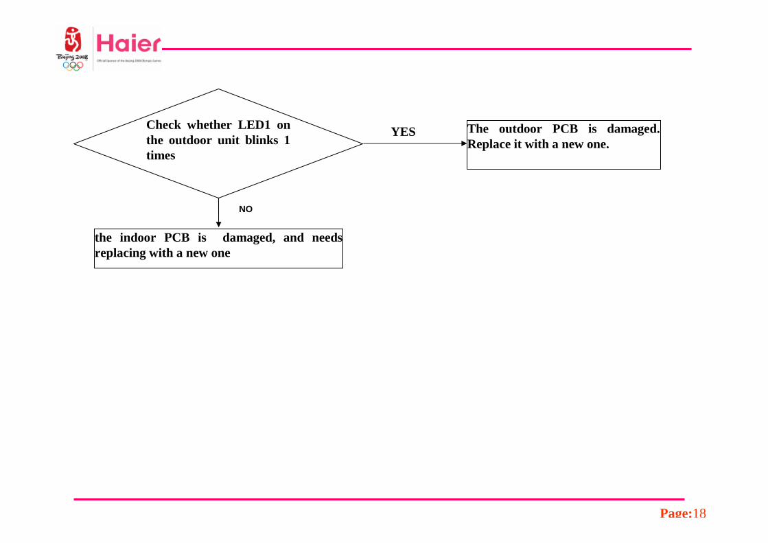
7. The EEPROM Abnormality (Indoor or outdoor unit)
Indoor Display E4 Indoor EEPROM error
F12Outdoor EEPROM error
Method of : the Data detected by the EEPROM are
Malfunction used to determine MCU
Detection
Malfunction when the Data of EEPROM is error or the Decision EEPROM is damaged
Conditions
Supposed Faulty EEPROM data
Causes Faulty EEPROM
Faulty PCB
Page:18
Check whether LED1 on the outdoor unit blinks 1 times
The outdoor PCB is damaged. Replace it with a new one.
the indoor PCB is damaged, and needs replacing with a new one
NO
YES

Page:19
8. Communication error between the indoor and outdoor units
Indoor display E7 Outdoor: display LED1 flash 15 times
Method of The data received from the another unit in Malfunction indoor unit-outdoor unit signal
Detection transmission is checked whether is normal
Malfunction When the data sent from outdoor unit
Decision cannot be received normally,or when the
Conditions content of the data is abnormal
Supposed indoor unit- outdoor unit signal Causes transmission error due to wiring error
Faulty indoor PCB Faulty outdoor PCB
Faulty power module

Page:20
Restart the unit and it becomes normally.
If starting up normally, but malfunction occurs again after a while
Check whether the linking cable between the indoor and outdoor is well connected or whether its core wires are well insulated.
The outdoor mainboard needs dehumidification.
The outdoor PCB needs dedust.
1. Reconnect the linking cable;2. Replace the linking cable with new one.
Yes
Yes
Yes
No
No
No
Page:21
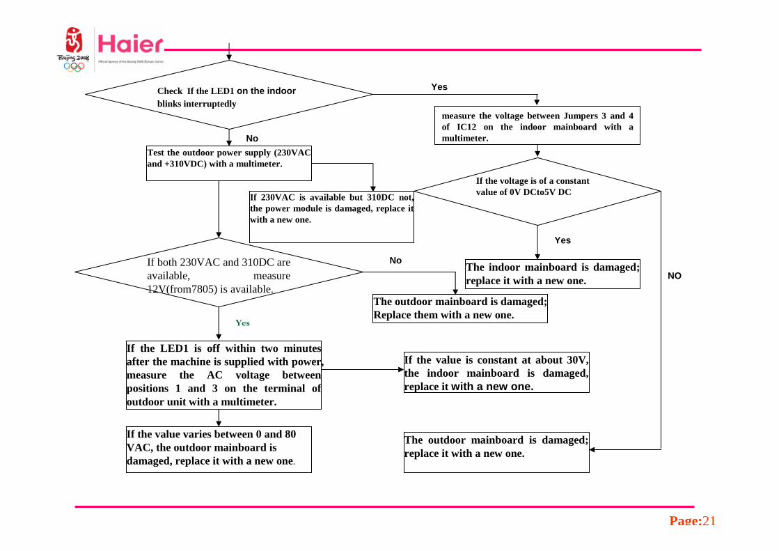
YesCheck If the LED1 on the indoorblinks interruptedly
No
If the voltage is of a constant value of 0V DCto5V DC
Yes
measure the voltage between Jumpers 3 and 4 of IC12 on the indoor mainboard with a multimeter.
NO
The outdoor mainboard is damaged; Replace them with a new one.
If the LED1 is off within two minutes after the machine is supplied with power, measure the AC voltage between positions 1 and 3 on the terminal of outdoor unit with a multimeter.
If 230VAC is available but 310DC not, the power module is damaged, replace it with a new one.
Test the outdoor power supply (230VAC and +310VDC) with a multimeter.
The outdoor mainboard is damaged; replace it with a new one.
The indoor mainboard is damaged; replace it with a new one.
If the value varies between 0 and 80 VAC, the outdoor mainboard is damaged, replace it with a new one.
If the value is constant at about 30V, the indoor mainboard is damaged, replace it with a new one.
If both 230VAC and 310DC are available, measure 12V(from7805) is available.
No
Yes

Page:22
R16
10K
C6102
C7102
IC2
R15
330
R182.2K
R14 1M
C5103
R132.2K
D6
1N4007D5
1N4007
R12
2W6.8K1
N
1
COM
R17
10K
+5
1
24
56
INDOOR UNIT
IC1
LED1
DQ12SD1781K
receive
send
+5V
TLP371R1 820
SEND
R2
1M
C1 0.001UF
R96.8K
R106.8K
R116.8K
D4 1N4007
R81M
C4
22UF/400VDC
D3
1N4007
D2
1N4007
C30.01UF
R61K
R510K
R710K
D1 1N4007
OUTDOOR UNIT
1
COM
1
N
1
LPOWER
IC4
R310K
R4
10KC20.01UF
+5V
RECEIVE

Page:23
9. High work-intense protection
Indoor display E9
Method of High work-intense control is activated in the heating
Malfunction mode if the temperature being sensed
Detection by the heat exchanger thermistor exceeds the limit.
Malfunction Activated when the temperature being sensed by the
Decision heat exchanger thermistor rises above
Conditions 74 twices in 30 minutes.
Supposed Dirty filter
Causes Dirty heat exchanger
Faulty heat-exchange sensor
over full gas

Page:24
YES
NO
the malfunction is reported after the machine has run for a little time ?
Check room temperature and pipe temperature sensor.
Electrify the machine again and turn it on ,check whether the wind temperature is below 74
the indoor unit blows poorly due to blocked filters or poor condition of the fan?
1) Clean the filters2) Reinstall the fan .
Use some tools to measure the pressure of system
The system is over charged with gas
YES
YES
NO

Page:25
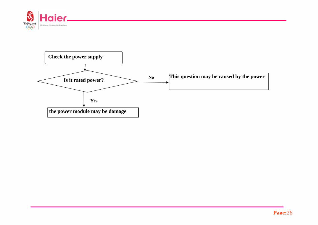
10. Power Supply Over or under voltagve fault
Indoor display F11
Outdoor display: LED1 flash 6 times
Method of An abnormal voltage rise or fall is detected by checking
Malfunction the specified voltage detection circuit
Detection.
Malfunction The DC voltage between “P” and “N”Decision is below 150v or up 390v
Conditions Supply voltage not as specified
Supposed the IPM module is broken
Causes the outdoor PCB is broken
Page:26
This question may be caused by the power
the power module may be damage
Check the power supply
Is it rated power? No
Yes

Page:27
11. Loop of the station detect error
Outdoor Display : LED1 flash 19 times
Indoor Display : F11
Method of : the position of the compressor rotor can not
Malfunction detected normally
Detection
Malfunction : when the The wiring of compressor is wrong
Decision or the connection is poor; or the compressor Conditions is damaged
Supposed : Faulty The wiring of compressor
Causes Faulty compressor
Faulty PCB

Page:28
YES
NO
1. The wiring of compressor is incorrect or the connection is poor;
2. The compressor is damaged
IPM Module is damaged and needs replacing.
At frist, the compressor start up ,soon the compressor stopped with the LED1 on the outdoor PCB blinks1Hzfor 19 times
the Malfunctions exist also, . The compressor is damaged replace a new one
Within 3 minutes after the machine is supplied with power and turned on, the compressor could not star up

Page:29
12. Over-current of the compressor
Outdoor Display : LED1 flash 24 or 25 times
Method of : The current of the compressor is too highMalfunction Detection
Malfunction : when the IPM Module is damaged Decision or the compressor is damaged Conditions power supply. voltage is too low or too high
Supposed : Faulty IPM Module Causes Faulty compressor
Faulty power supply

Page:30
IPM Module is damaged
The compressor is started normally, but malfunctions are reported after it has run for some time. Check the power supply. If the voltage is too low or too high
Repair the power supply
No
Yes
Electrify the machine again and turn it on ,If malfunctions are reported before or upon the compressor being started up,
YesTest if the resistance values
among Phases U, V and W of compressor are equal and about 1 and 3Ω.
,
compressor is damaged

Page:31
A/D
PWMPWM
A/D
PWM
PAM
PMSM
Is Ed
Im