husqvarna construction products -...
TRANSCRIPT

HUSQVARNA CONSTRUCTION PRODUCTS
FS305 FS309
Operator’s manual Manuel d’utilisation et d’entretien Manual de explicaciones
EN FR ES

DECLARATION DE CONFORMITE AUX DIRECTIVES EUROPEENNES
DECLARATION OF CONFORMITY WITH EUROPEAN DIRECTIVES
HUSQVARNA CONSTRUCTION PRODUCTS, 433 81 Gothenburg, Sweden, déclare que la machine FS305, FS309 est conforme aux dispositions des DIRECTIVES :
HUSQVARNA CONSTRUCTION PRODUCTS, 433 81 Gothenburg, Sweden, herewith declares that the machine FS305, FS309 conforms to the DIRECTIVES :
• "MACHINES" modifiées (89/392/CEE) • "BASSE TENSION" modifiées (73/23/CEE) • "CEM” (89/336/CEE) • ”BRUITS” (2000/14/CEE) • ” DECHETS D’EQUIPEMENTS ELECTRIQUES ET
ELECTRONIQUES (DEEE) ” (2002/96/CE)
• "MACHINES" modified (89/392/CEE) • "LOW VOLTAGE" modified (73/23/CEE) • "EMC” (89/336/CEE) • ”NOISE” (2000/14/CEE) • ” WASTE ELECTRICAL AND ELECTRNIC EQUIPEMENT
(WEEE) ” (2002/96/EC)
EG-RICHTLIENIEN – KONFORMITÄTS-ERKLÄRUNG
DECLARACIÓN DE CONFORMIDAD CON LAS DIRECTIVAS EUROPEAS
HUSQVARNA CONSTRUCTION PRODUCTS, 433 81 Gothenburg, Sweden, erklärt hiermit, daß die machine FS305, FS309 konform ist, mit der :
HUSQVARNA CONSTRUCTION PRODUCTS, 433 81 Gothenburg, Sweden, dclara que la máquina FS305, FS309 es conforme a las disposiciones de las DIRECTIVAS :
• "MACHINENBAURICHTLINIE" in Änderungs-fassung (89/392/CEE)
• "NIEDERSPANNUNGSRICHTLINIE" in Änder-ungsfassung (73/23/CEE)
• Linie "ELEKTROMAGNETISCHESTÖR-SICHERHEIT” (89/336/CEE)
• ”LÄRMSCHUTZRICHTLINIE” (2000/14/CEE) • ” ELEKTRO-UND ELEKTRONIK-ALTQERATE“(2002/96/EG)
• "MÁQUINAS" modifiées (89/392/CEE) • "BAJA TENSION" modifiées (73/23/CEE) • "CEM” (89/336/CEE) • ”RUIDOS” (2000/14/CEE) • ”RESIDUOS DE APARATOS ELECTRICOS Y
ELECTRONICOS” (2002/96/CE)
DICHIARAZIONE DI CONFORMITA' ALLE DIRETTIVE EUROPEE
VERKLARING VAN CONFORMITEIT MET DE EUROPESE RICHTLIJNEN:
HUSQVARNA CONSTRUCTION PRODUCTS, 433 81 Gothenburg, Sweden, dichiara che la macchina FS305, FS309 est conforme e conforme alle disposizioni della DIRETTIVA :
HUSQVARNA CONSTRUCTION PRODUCTS, 433 81 Gothenburg, Sweden, verklaart dat de machine FS305, FS309 voldoet aan de eisen van de volgende RICHTLIJNEN:
• "MACCHINE" modificata (89/392/CEE) • "BASSA TENSIONE" modificata (73/23/CEE) • "CEM” (89/336/CEE) • ”RUMORI” (2000/14/CEE) • ”DI APPARECCHIATURE ELETTRICHE ED
ELETTRONICHE (RAEE) ” (2002/96/CE)
• "MACHINES", gewijzigd (89/392/EEC) • "LAAGSPANNING", gewijzigd (73/23/EEC) • "CEM” (89/336/EEC) • ”GELUID” (2000/14/EEC) • ” AFGEDANKTE ELEKTRISCHE EN ELEKTRONISCHE
APPARATUUR (AEEA) ” (2002/96/EG)
FÖRSÄKRAN OM ÖVERENSSTÄMMELSE ENLIGT EU-DIREKTIVEN:
DECLARAÇÃO DE CONFORMIDADE COM AS DIRECTIVAS EUROPEIAS:
HUSQVARNA CONSTRUCTION PRODUCTS, 433 81 Gothenburg, Sweden, intygar härmed att maskinen FS305, FS309 uppfyller villkoren i följande DIREKTIV:
HUSQVARNA CONSTRUCTION PRODUCTS, 433 81 Gothenburg, Sweden, declara que a máquina FS305, FS309 está em conformidade com as disposições das DIRECTIVAS:
• "MASKINER" och senare ändringar (89/392/CEE) • "LÅGSPÄNNINGAR" och senare ändringar (73/23/CEE) • "ELEKTROMAGNETISK KOMPATIBILITET"
(89/336/CEE) • "BULLER" (2000/14/CEE) • ”ELEKTRISKA ELLER ELEKTRONISKA PRODUKTER
(WEEE) ” (2002/96/EG)
• "MÁQUINAS" modificadas (89/392/CEE) • "BAIXA TENSÃO" modificadas (73/23/CEE) • "CEM” (89/336/CEE) • ”RUÍDOS” (2000/14/CEE) • ” RESIDUOS DE EQUIPAMENTOS ELECTRICOS E
ELECTRONICOS (REEE) ” (2002/96/CE)
Christer Carlberg, Operations Manager
Husqvarna Construction Products

FIG. 1 ABB. 1 FIG. 2 ABB. 2
FIG. 3 ABB. 3
FIG. 4 ABB. 4
FIG. 5 ABB. 5


EXPLANATION OF SYMBOLS – WARNINGS
6 - English
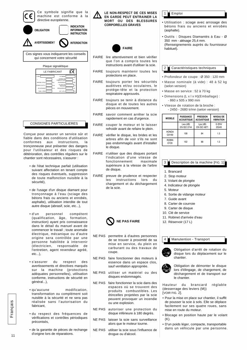
Explanation of the symbols Use of pictograms on the machines (in color) and in the manual indicate safety warnings
WATCH OUT! DANGER! General danger signal. REQUIREMENT. The following must always be used with the machine: • certified safety helmet • certified ear protection • certified safety goggles or certified
eyeshade. Read manual. Carefully READ and assimilate the user’s manual before operating the machine. WARNING. Triangle and black marking on yellow background. Danger if instructions are ignored. Risk of injury to user or third party. Risk of damage to machine or tool. PROHIBITED. Red circle with or without diagonal bar. Use or presence forbidden. INFORMATION or specific instructions on how to use or check the machine. This machine complies with the EC directive in force. STOP symbol.
Safety goggles or eyeshade must be worn. Loud noise in environment as defined by European Community directive. Disk rotation must stop when moving the machine at the work site. Disk must be removed during slinging, loading, unloading and transport at the worksite.

• Depth of cut : Ø 350: 120 mm
• Nominal weight (unladen) : 48 to 52 kg(depending on version)
• Service weight : 52 to 70 kg (includingtank)
• Dimensions (LxWxH) :- 860 x 505 x 990 mm
• Speed of spindle rotation :- 2450-2680 rpm(depending on version)
2 Technical specifications
• Uti l isat ion : sawing with sprinkling offresh, old or coated (asphalt) concrete.
• Too ls : Water-cooled diamond-impregnated discs - Øx350 mm - bore25.4 mm.(Details from your usual supplier).
1 Use
7
Switch off the disk prior to movingthe machine on jobsite.
Remove the disk prior to hoisting,loading, unloading and transportingthe machine on jobsite.
SPECIAL INSTRUCTIONS
The disc cutter is designed to provide safeand reliable service in operating conditionscorresponding with the instructions, but itcan present dangers for the user and risksof damage, consequently regular on siteinspection is necessary to ensure :
• Perfect technical condition (use forthe purpose for which it is intendedand taking into account any risks, andcorrection of any malfunctiondetrimental to safety).
• Use a diamond disk for cutting withwater (sawing new or old concrete,tarmac or asphalt). No other type ofdisk is allowed (abrasive, saw, etc...).
• Competent staff (qualifications, age,training) who have read andunderstood the manual in detailbefore starting work: any electrical,mechanical or other problem shouldbe investigated by a qualif iedmaintenance engineer (electrician,maintenance manager, approveddealer, etc . . .).
• That the warnings and instructionsmarked on the machine are followed(adequate personal protection,correct use, general safetyinstructions, etc).
• That no modification, transformationor addition is detrimental to safetyand that it is carried out without priorauthorization from the manufacturer.
• Respect of the maintenance intervalsand periodical checks recommended.
• That only genuine spare parts areused for repairs.
FAILURE TO COMPLY WITHTHESE WARNINGS COULDRESULT IN DEATH OR SERIOUSBODILY INJURY.
3 Description of the machine [FIG. 1]
11. Handle12. Motor stop13. Lowering handwheel14. Graduated scale15. Engine16. Engine oil drain17. Front guide18. Belt cover19. Disk casing10. Service spanner11. Water intake tap12. Tank (17 litres)
4 Handling - Transport
He igh t o f ad jus tab le hand lebars(unscrew the lever (M))[SEE FIG. 2].
• The ground-saw only needs pushing tomove it into position on the site. It is easyto move on its four wheels, withoutstarting the motor.
• The handwheel (K) locks the machineitself in the high position.
• Light weight, compact, transportable in avehicle by one person.
MANDATORYINDICATIONINFORMATIONINSTRUCTION
WARNING PROHIBITION
These signs give adviceconcerning your safety
DO carefully read and understand all theinstructions before operating the saw.
DO always keep all guards in place.
DO aways wear safety approved hearing,eye, head and respiratory protection.
DO keep all parts of your body away fromthe blade and all other moving parts.
DO know how to stop the saw quickly incase of an emergency.
DO shut off the engine and allow it to coolbefore refueling.
DO inspect the blade, flanges and shaftsfor damage before install ing theblade.
DO use only blades marked with amaximum operating speed greaterthan the blade shaft speed.
DO use caution and follow theinstructions when loading andunloading the saw.
DO NOT allow other persons to be nearthe saw when starting, refuelingor when cutting.
DO NOT operate gasoline engines in anenclosed area unless it isproperly vented.
DO NOT use damaged equipment orblades.
DO NOT operate the saw in areas ofcombustible material. Sparksfrom the saw could cause a fireor an explosion.
DO NOT allow blade exposure from theguard to be over 180 degrees.
DO NOT leave the saw unattended withthe motor running.
DO NOT operate the saw while under theinfluence of drugs or alcohol.
This symbol indicates that themachine is in conformance withthe applicable European directive.
DO
DO NOT
HONDAGX160 108 84 1.3
ROBINEY20 102 88 1.3
MODELPOWERLEVEL
Lwa (dB)EN ISO 3744
Lpa (dB)EN ISO 4871
G ENV25349
PRESSURELEVEL
VIBRATIONLEVEL
En
glis
h
TYPETYPE SERIAL
POWER
VOLTAGE
FREQUENCY
INTENSITY
FABRICATIONYEAR
WEIGHT
MAXI TOOL
BORE
SPEED
MANUFACTURER
MASSE UTILE Kg
mm
mm
Ø MAXI OUTIL.
Ø ALESAGE
T/MN - RPM
N° SERIE
ANNEE DEFABRICATION
PUISSANCE kW
Hz
V
A
PLAGE DETENSION
FREQUENCE
INT. UTIL.
Instruction plate

8
Note the direction of rotationindicated by an arrow on oneside of the disc (direction ofrotation shown on the outside ofthe guard housing).Check the state of cleanliness ofthe disc support faces of theadaptor plates (B and C) and ofthe spindle.
The holding screw (D) of the dischas a right-hand thread.
8 Stopping the machine
• Turn the handwheel (K) to free the disk from the groove [SEE FIG. 4].
• No need to lock the saw up byreleasing the handwheel (K).
• Turn off the water supply (G).
• Allow the motor to run idle.
• Switch off the motor (refere to the motormaintenance manual).
6 Fitting the blade
• Place the machine in an high position.
• Make sure the engine is switched off..
• Unscrew the nuts (E) from the guardhousing [SEE FIG. 3].
• Remove the guard housing (A).
• Fit the diamond impregnated disc.
• Firmly tighten the screw (D) with thespanner provided with the machine,holding the disc steady by hand.
• Replace the protective guard (if this is notreplaced the casing safety switch willprevent the saw being started).
• Reconnect the water hose (mains withvalve or tank).
• Tighten the nut (E).
Motor off
• Turn off the water tap (G) (from the mainsor from the tank in order to fill it) [SEEFIG.x4].
• Mark out a line on the ground where a cuthas to be made.
• Position the machine so that the loweredfront guide (F) and the disc are alignedwith the line marked out (disc visble onthe belt side of the housing).
• Start up the motor : refer to the motormanufacturer’s instructions in the servicemanual.
• Allow the motor to warm up.
• Turn on the water supply tap (G) (fromthe mains or the water tank).
• Increase the motor speed to full.
• Hold the saw, turn the handwheel (K)and position the disk in contact with thefloor.
• Lower to the depth of cut required, andbearing in mind that each graduation ofthe scale corresponds to a depth of 1cm.Lower slowly to prevent the enginestalling.
• Gently move the machine forwardensuring that the front guide and the discare always aligned with the line markedout.
• After use, clean the machine.
• Lubrication : apply a moderate amount ofbearing lubricant to the nipples in thedepth adjustment chassis (depending onthe frequency of use).
• Model with petrol motor (refer to themotor maintenance manual).
■ Make sure the fuel is topped up.
■ Check the oil level; as the motor oftenworks at an angle, check it frequently inthe horizontal position that the oil levelis never below the second line on thegauge.
■ To start up, refer to the motorinstructions.
Take into account the workingconditions from health and safetypoint of wiew.
Use only blades marked with amaximum operating speedgreater than blade shaft speed
"Engine Maintenance" : refer tothe engine maintenance booklet.
Dispose of the old oil as laiddown by the regulations in force.
Motor off
Emergency stopOperate the switch (J) in frontof the engine.
Entrust repairs to authoriseddealer only
7 Starting up
Always pay extreme care andattention to the preparation ofthe machine before starting up
Remove all adjustment tools andwrenches from floor andmachine
Always keep blade guard inplace
Ensure that the water supply isabundant, when cutting wet.
• There may be several causes responsiblefor arresting the disc in the sawing grooveor stopping the machine: ■ Belt tension.■ Lack of fuel.■ Advance or lowering too fast, etc.
• In all case, disengage the disc from thegroove and give the machine a completecheck-over.
9 Incidents during sawing
The working area must becompletely cleared, well lit andall safety hazards removed (nowater or dangerous objects inthe vicinity)
The operator must wearprotective clothingappropriate to the work heis doing. We recommendthat this includes both eyeand ear protection
Any persons not involved in thework should leave the workingarea
The use of ear protection ismandatory.
5 Check before starting
Please read the instructions foruse prior to operating themachine for the first time.
Motor off.
• Check the engine oil everyday. Refer tothe engine manual for oi l changeschedule. Use :
■ SAE 10W30 motor oil with API classMS, SD, SE or better for PETROLengines.
■ API class CD or CE for Hatz diesel.
OIL
En
glis
h
10Maintenance (with theengine stopped)

9
13 Repairs
We carry out all repairs in theshortest possible time and at themost economical prices (seeoverleaf for our address).
SAV
14 Spare parts
For quick supply of spare parts and toavoid any lost time it is essential to quotethe data on the manufacturer's plate fixedto the machine and the part number of thepart to be replaced with every order.
In the event of deterioration andscrapping of the machine, thefollowing items must bedisposed of in accordance withthe requirements of thelegislation in force.
15 Scrapping
• Main materials :
• Motor : Aluminium (AL), Steel (AC),Motor : Copper (CU), Polyamide (PA)
• Machine : Steel sheet (AC),■ Machine : Cast iron (FT)■ Machine : Aluminium (AL)
The instructions for use and spare partsfound in this document are for informationonly and are not binding.As part of our product quality improvementpolicy, we reserve the right to make anyand all technical modifications without priornotice.
It may be necessary after using a few timesto retension the belts, without over-tightening them. To do this :
• loosen the 2 nuts (S) fixing the motor tothe chassis, without removing them[SEE FIG. 5];
• tighten the tensioning nuts (N), thesescrews pull the motor up..
• at normal tension, tighten the motorfixing nuts (S).
11 Engine belt tension
• Periodically, tighten the nuts and boltsand particularly after the first few hours ofuse.
• Check belt tensions, tighten them withoutoverdoing it.
• When garaged, it is recommended thedisc be removed and suitably stored.
• Make sure the disc is correctly tightened.
• Make sure the disc supports surfaces, theadaptor plates and the spindle are keptclean.
12 Important advice
The manufacturer declines allresponsibility for loss or damageresulting from misuse or anymodification, alteration orpowering that does not conformto the manufacturer's originalspecifications.
At the work station, the soundpressure level may exceed85xdbx(A)
In this case individual protectionmeasures must be taken.
When working in a limited orclosed area, make sure that theventi lation is adequate. Theexhaust gases contain carbonmonoxide (exposure to this toxicgas can cause loss ofconsciousness and can be fatal).
AIR FILTER
• Read engine owners manual formaintenance intervals. For extremelydusty conditions you may have to cleanthe air filter element 2 to 3 times a day.
• Replace any damaged filters or gaskets.
Store in a safe place, out ofreach of children
Maintain tools carefully
Store in a safe place out ot reachof children.
Remove all adjustment tools andwrenches
Store diamond tool in a safeplace so it cannot be bent ordamaged.
En
glis
h
• To change the oil, remove the disk, lowerthe saw to the lowest position and thenplace the tray by the drain outlet (L) [SEEFIG. 4].
See exploded view
00000000 (0)
Item number Quantity

EXPLICATION DES SYMBOLES – CONSIGNES
10 - Français
Explication des symboles L'emploi de pictogrammes sur les machines (en couleur) et dans le manuel indiqueront des conseils qui concernent votre sécurité.
ATTENTION ! DANGER ! Symbole général de danger. OBLIGATION. Toujours utiliser avec la machine : • un casque de protection homologué • des protections d’oreilles homologuées • des lunettes de protection homologuées
ou une visière homologuée. Veuillez lire le manuel. LIRE attentivement et bien assimiler le manuel d’utilisation avant d’utiliser la machine. AVERTISSEMENT. Triangle et marquage noir sur fond jaune : danger si non respect. Risque de blessures pour l’utilisateur ou des tiers. Risques de dégâts sur la machine ou l’outil. INTERDICTION. Cercle rouge avec ou sans barre : utilisation ou présence interdite. INDICATION. Information – Instruction : indications particulières concernant l’utilisation ou le contrôle de la machine. Cette machine est conforme à la directive CE en vigueur. Le symbole ARRET. Port de lunettes protectrices ou visière obligatoire.
Emissions sonores dans l’environnement selon la directive de la Communauté européenne. Obligation d'arrêt de rotation du disque lors du déplacement sur le chantier. Obligation de démonter le disque lors d'élingage, de chargement, de déchargement et de transport sur le chantier.
• Profondeur de coupe : Ø 350 : 120 mm
• Masse nominale (à vide) : 48 à 52 kg(selon version)
• Masse en service : 52 à 70 kg
• Dimensions (L x l x H)(Emballage) :- 860 x 505 x 990 mm
• Vitesse de rotation de la broche :- 2450 - 2680 tr/mn (selon version)
2 Caractéristiques techniques
• Util isation : sciage avec arrosage desbétons frais ou anciens et enrobés(asphalte).
• Outi ls : Disques Diamantés à Eau - Ø350xmm - alésage 25,4 mm.(Renseignements auprès du fournisseurhabituel).
1 EmploiF
ran
çais
11
Obligation d'arrêt de rotation dudisque lors du déplacement sur lechantier.
Obligation de démonter le disquelors d'élingage, de chargement, dedéchargement et de transport surle chantier.
CONSIGNES PARTICULIERES
Conçue pour assurer un service sûr etfiable dans des conditions d'utilisationconformes aux instructions, latronçonneuse peut présenter des dangerspour l 'uti l isateur et des risques dedétérioration, des contrôles réguliers sur lechantier sont nécessaires, s'assurer :
• de l'état technique parfait (utilisationsuivant affectation en tenant comptedes risques éventuels, suppressionde toute malfonction nuisible à lasécurité),
• de l'usage d'un disque diamant pourtronçonnage à l 'eau (sciage desbétons frais ou anciens et enrobés,asphalte), utilisation interdite de toutautre disque (abrasif, scie, etc...),
• d'un personnel compétent(qualif ication, âge, formation,instruction) ayant pris connaissancedans le détail du manuel avant decommencer le travail ; toute anomalieélectrique, mécanique ou d'autreorigine sera contrôlée par unepersonne habil i tée à intervenir(électricien, responsable del'entretien, agent revendeur agréé,etc...),
• s'assurer du respect desavertissements et directives marquéssur la machine (protectionsadéquates personnelles), utilisationconforme, instructions de sécurité engénéral...),
• qu'aucune modification,transformation ou complément soitnuisible à la sécurité et ne sera pasréalisée sans l 'autorisation dufabricant,
• du respect des fréquences devérifications et contrôles périodiquespréconisés,
• de la garantie de pièces de rechanged'origine lors de réparations.
LE NON-RESPECT DE CES MISESEN GARDE PEUT ENTRAINER LAMORT OU DES BLESSURESCORPORELLES GRAVES
3 Description de la machine [FIG. 1]
11. Brancard12. Stop moteur13. Volant de plongée14. Indicateur de plongée15. Moteur16. Sortie de vidange moteur17. Guide avant18. Carter de courroie19. Carter de disque10. Clé de service11. Robinet d'arrivée d'eau12. Réservoir (17 L)
4 Manutention - Transport
Hauteur du brancard rég lab le(desserrage des leviers (M))[VOIR FIG. 2].
• Pour la mise en place sur chantier, il suffitde pousser la scie à sols. Elle se déplacefacilement sur ses quatre roues, sansmise en route du moteur.
• Blocage en position haute par le volant(K).
• D'un poids léger, compacte, transportabledans un véhicule par une personne.
OBLIGATIONINDICATIONINFORMATIONINSTRUCTION
AVERTISSEMENT INTERDICTION
Ces signes vous indiqueront les conseilsqui concernent votre sécurité FAIRE lire attentivement et bien vérifier
que l 'on a compris toutes lesinstructions avant d'utiliser la scie.
FAIRE toujours maintenir toutes lesprotections en place.
FAIRE toujours porter les sécuritésaudit ives et/ou occulaires, leprotège-tête et la protectionrespiratoire approuvés.
FAIRE toujours se tenir à distance dudisque et de toutes les autrespièces en mouvement.
FAIRE savoir comment arrêter la scierapidement en cas d'urgence.
FAIRE couper le moteur et le laisserrefroidir avant de refaire le plein.
FAIRE vérifier le disque, les brides et lesarbres afin de voir s'ils ne sontpas endommagés avant d'installerle disque.
FAIRE n'utiliser que des disques portantl ' indication d'une vitesse defonctionnement maximalesupérieure à la vitesse de l'arbrede disque.
FAIRE preuve de prudence et respecterles instructions lors duchargement et du déchargementde la scie.
NE PAS permettre à d'autres personnesde se trouver à proximité de samise en service, du plein encarburant ou des travaux decoupe.
NE PAS faire fonctionner des moteurs àessence dans un espace clos,sauf ventilation appropriée.
NE PAS uti l iser un matériel ou desdisques endommagés.
NE PAS faire fonctionner la scie dans desespaces où se trouvent desproduits combustibles. Lesétincelles projetées par la sciepeuvent provoquer un incendieou une explosion.
NE PAS autoriser une protection dudisque inférieure à 180 degrés.
NE PAS laisser la scie sans surveillancealors que le moteur tourne.
NE PAS utiliser la scie sous l'influence dedrogue ou d'alcool.
Ce symbole signif ie que lamachine est conforme à ladirective européenne.
TYPE
LE FABRICANT
MASSE UTILE Kg
mm
mm
Ø MAXI OUTIL.
Ø ALESAGE
T/MN - RPM
N° SERIE
ANNEE DEFABRICATION
PUISSANCE kW
Hz
V
A
PLAGE DETENSION
FREQUENCE
INT. UTIL.
Plaque signalétique
FAIRE
HONDAGX160 108 84 1.3
ROBINEY20 102 88 1.3
MODELEPUISSANCE
ACOUSTIQUE
Lwa (dB)EN ISO 3744
Lpa (dB)EN ISO 4871
G ENV25349
PRESSIONACOUSTIQUE
NIVEAU DEVIBRATION
NE PAS FAIRE

Fra
nça
is
12
Tenir compte de son sens derotation repéré par une flèchesur l'une de ses faces (sens derotation sur le flanc droit ducarter).
Vérifier l'état de propreté desfaces d'appui du disque, desflasques (B et C) et de la broche.
La vis de serrage (D) du disquepossède un filetage avec un pasà droite
8 Arrêt
• Manoeuvrer le volant de plongée (K), pourdégager le disque de la rainure [VOIRFIG.x4].
• Aucun blocage n'est nécessaire, la machi-ne reste en position haute.
• Fermer l'arrivée d'eau (G).
• Laisser tourner le moteur au ralenti.
• Arrêter le moteur (se reporter au livretd'entretien moteur).
6 Montage du disque
• Mettre la machine en position haute.
• S'assurer que le moteur est bien àl'arrêt (Bouton stop (J) en position "O").
• Desserrer les écrous (E) du carter[VOIR FIG.x3].
• Basculer la partie avant du carter (A).
• Monter le disque diamanté.
• Bloquer fermement la vis (D) à l'aide dela clé fournie avec la machine enimmobilisant le disque avec la main.
• Remettre le carter de protection(obligatoire pour la sécurité carter, sinondémarrage impossible).
• Raccorder le flexible à eau (réseau avecvanne ou réservoir).
• Serrer les écrous (E).
Arrêt moteur
• Fermer le robinet d'eau (G) (du réseau oudu réservoir pour le remplir) [ VOIRFIG.x4].
• Tirer "au bleu" un trait sur le sol, àl'emplacement à tronçonner.
• Positionner la machine de telle façon quele guide avant rabattu (F) et le disquecoïncident avec le tracé (disque visiblecôté carter de courroies).
• Procéder à la mise en marche du moteur:se reporter aux instructions du manuel deservice du constructeur.
• Laisser chauffer le moteur.
• Ouvrir le robinet d'arrivée d'eau (G) (duréseau ou du réservoir).
• Augmenter la vitesse du moteur à pleinrégime.
• Maintenir la machine, actionner le volant (K) et amener le disque en contact avecle sol.
• Procéder à la descente jusqu'à laprofondeur de coupe désirée à l'aide duvolant. Sur l'indicateur de plongée, unegraduation correspond à une plongéede 1cm. Une descente lente est conseilléepour éviter de caler le moteur.
• Faire avancer doucement la machine ens'assurant que le guide avant et le disquecoïncident toujours bien avec le tracé.
10 Entretien (arrêt obligatoire du moteur)
• Après chaque usage, nettoyer lamachine.
• Graissage : alimenter modérément lesgraisseurs du châssis de réglage deprofondeur avec de la graisse àroulement (suivant la fréquenced'utilisation).
• Machine à moteur essence (se reporterau livret d'entretien moteur)
■ S'assurer du plein de carburant.
■ Vérifier le niveau d'huile: le moteurtravail lant souvent incliné, vérif ierfréquemment, en position horizontale,que son niveau d'huile ne soit jamaisinférieur au deuxième trait de la jauge.
■ Pour le démarrage, se reporter à lanotice des moteurs.
Tenir compte des conditionsambiantes (santé et sécurité).
N'uti l iser que des disquesmarqués d'une vitesse maximalede travail supérieure à la vitesseeffective de la broche
"Entretien moteur" : se reporterau livret d'entretien moteur.
Le lubrif iant sera éliminéconformément aux modalitésprescrites par la législation envigueur.
Arrêt moteur.
L'interrupteur (J) se trouve àl 'avant droit de la machine,sur le moteur thermique.
Faire réparer par une personnequalifiée.
7 Mise en service
Rester toujours attentif.
Avant la mise en service, enleverles clés et outils de réglage dusol ou de la machine.
Maintenir le carter de protectionen place pendant toute la duréedu travail.
Arrosage abondant =longévité assurée du disque
• Plusieurs causes peuvent êtreresponsables de l'arrêt du disque dans larainure de sciage ou de la machine :■ Tension des courroies,■ Défaut de carburant,■ Avance ou plongée trop rapide, etc.
• Dans tous les cas, dégager le disque dela rainure et faire un contrôle complet dela machine.
9 Incident en cours de sciage
Le champ de travail doit êtreparfaitement en ordre, bien éclairé,et ne doit présenter aucun risque(ni-humidité, ni produits dangereuxà proximité).
L'opérateur doit porter desprotections appropriées autravail.
Toute personne étrangère doit êtreécartée du champ de travail.
Obligation port du casqueantibruit.
5 Vérification avant mise en service
Avant toute mise en service, lireattentivement la notice, et sefamiliariser avec la machine.
Arrêt moteur
• Vérifier l'huile moteur quotidiennement.Se référer au manuel du moteur pour lesintervalles de remplacement de l'huile.Utiliser :
• Une huile moteur SAE 10W30 avecclasse API MS, SD, SE ou supérieurepour les moteurs à essence.
• Une huile classe API CD ou CE pourles moteurs diesels.
HUILE

Fra
nça
is
13
13 Réparation
Vous adresser à votre fournisseurqui est à votre entière dispositionpour vous assurer toute réparationdans les délais les plus réduits etaux meilleurs prix.
SAV
14 Pièces de rechange
Pour une livraison rapide des pièces derechange et afin d'éviter toute perte de temps,i l est nécessaire de rappeler à votrefournisseur lors de chaque commande lesindications qui f igurent sur la plaquesignalétique de la machine, ainsi que laréférence de la pièce à remplacer.
En cas de détérioration et de cassede la machine, ceux-ci serontéliminés conformément auxmodalités prescrites par lalégislation en vigueur.
15 Mise au rebut
• Matériaux principaux :
• Moteur : Aluminium (AL) - Acier (AC)n Moteur : Cuivre (CU) - Polyamide (PA)
• Machine : Tôle acier (AC) - Fonte (FT)n Machine : Aluminium (AL)
Les conseils d'utilisation et pièces détachéesfigurant sur ce document sont donnés à titred'information et non d'engagement.Soucieux de la qualité de nos produits, nous nousréservons le droit d'effectuer, sans préavis, toutesmodifications techniques en vue de leuramélioration.
Après quelque temps d'utilisation, il peutêtre nécessaire de retendre, sansexagération, les courroies. Pour cela :
■ Débloquer les 2 écrous (S) fixant lemoteur au châssis, sans les enlever[VOIR FIG. 5].
■ Visser les écrous de tension (N), cesécrous poussent le moteur vers le haut.
■ A tension normale, bloquer les écrousde serrage (S) du moteur.
11 Tension de la courroie moteur
• Périodiquement, resserrer la boulonnerie,et tout spécialement après les premièresheures de fonctionnement.
• Vérifier la tension des courroies, lestendre sans exagération.
• En position garage, il est recommandéd'enlever le disque et de le stockerconvenablement.
• Effectuer un serrage correct du disque.
• Veiller à la propreté des surfaces d'appuidu disque, des flasques et de la broche.
12 Recommandations importantes
Le fabricant décline touteresponsabilité résultant d'unemploi inadapté, de toutemodification, adaptation oumotorisation non conforme à ladéfinition d'origine prévue par leconstructeur.
Au poste de travail, la puissancesonore peut dépasser 85 db (A).Dans ce cas, des mesuresindividuelles de protectiondoivent être prises.
Dans le cas de travail dans unendroit restreint ou fermé,assurez-vous d'une ventilationadéquate, les gazd'échappement contenant del 'oxyde de carbone (uneexposition à ce gaz toxique peutprovoquer une perte deconscience et être mortelle).
FILTRE A AIR
• Se référer au manuel du moteur pour lesintervalles d'entretien. Pour desconditions extrêmement poussiéreuses, ilfaudra parfois nettoyer l'élément filtrant 2à 3 fois par jour.
• Remplacer tous les filtres ou garnituresd'étanchéité endommagés.
Stocker dans un endroit sûr,hors de portée des enfantsEntretenir soigneusement lesoutils
Remiser les produits dans unendroit sûr, hors de portée desenfants.Enlever tous les outi ls deréglage et les clés.Remiser l'outil diamanté à unendroit où il ne pourra pas êtrefaussé ou endommagé.
Voir vue éclatée
00000000 (0)
Code Quantité
• Pour vidanger le moteur, démonter ledisque, descendre la machine en positionbasse maximum, puis présenter le bac àla sortie de vidange (L) [VOIR FIG. 4].

EXPLICACIÓN DE LOS SÍMBOLOS – CONSIGNAS
14 - Español
Explicación de los símbolos El empleo de pictogramas en las máquinas (de color) y el manual indicarán consejos relativos a la seguridad.
¡ATENCIÓN! ¡PELIGRO! Símbolo general de peligro. OBLIGACIÓN. Utilizar siempre con la máquina: • un casco de protección homologado • protecciones auriculares homologadas • gafas protectoras homologadas o una
visera homologada. Lea el manual LEER atentamente y comprender bien el manual de utilización antes de usar la máquina. ADVERTENCIA. Triángulo y marcado negro en fondo amarillo: peligro si no se respeta. Riesgo de herida para el usuario o algún tercero. Riesgos de daños en la máquina o la herramienta. PROHIBICIÓN. Círculo rojo con o sin barra: utilización o presencia prohibida. INDICACIÓN. Información – Instrucción: indicaciones especiales relativas a la utilización o el control de la máquina. Esta máquina está en conformidad con la directiva CE vigente. Símbolo PARADA. Obligación llevar gafas protectoras o visera.
Emisiones sonoras en el entorno según la directiva de la Comunidad Europea. Obligación detener la rotación del disco durante el desplazamiento en la obra. Obligación de desmontar el disco en caso de eslingado, carga, descarga y transporte en la obra.

15
Montar el disco de modo que laflecha de dirección de rotación(en una cara del disco) coincidacon la f lecha en el costadoderecho del cárter.
Comprobar si las superficies decontacto del disco, de lossoportes (B y C) y del eje estánlimpias.
El tornillo de sujeción (D) deldisco tiene rosca a derechas.
8 Parada
• Levantar la perilla (K) y tirar hacia sípara liberar el disco de la ranura [VEASEFIG. 4].
• Bloquear la máquina en posición altasoltando la palanca (K).
• Cierre la alimentación de agua (G).
• Deje funcionar el motor en régimenmínimo.
• Pare el motor (véase el fol leto deinstrucciones de mantenimiento).
6 Montaje del disco
• Ponga la máquina en posición alta.
• Comprobar si pare el motor..
• Afloje las tuercas (E) del cárter [VEASE FIG.x3].
• Retire el cárter (A).
• Monte el disco de diamante.
• Mantener el disco inmóvil con la mano yapretar bien el tornillo (D) utilizando lallave suministrada con la máquina.
• Poner el cárter de protección (obligatoriopara la seguridad cárter; de lo contrario elarranque es imposible).
• Conectar la manguera de agua (grifo dedistribución o depósito).
• Apretar la tuerca (E).
Parada del motor.
• Cierre el grifo de agua (G) (distribución opara llenar el depósito) [VEASE FIG. 4].
• Haga un trazo en el suelo donde debecortar.
• Coloque la máquina en la posiciónapropiada: con la guía frontal (F) y eldisco sobre el trazo (disco visible por elcárter de las correas).
• Ponga el motor en marcha de acuerdocon las instrucciones de servicio delfabricante.
• Deje calentar el motor.
• Abra el grifo de aspersión de agua (G)(distribución o depósito).
• Acelere el motor a régimen máximo.
• Sujetar la máquina, levantar la perilla(K) con el pie y desplazar el disco hastaque se ponga en contacto con el suelo.
• Efectuar la bajada hasta la profundidadde corte deseada (hasta escuchar unclic), teniendo en cuenta que cadamuesca de la perilla corresponde a unaprofundidad de 1 cm. Se recomiendaproceder lentamente para evitar que elmotor se cale.
• Haga avanzar la máquina lentamente,manteniendo el disco y la guía frontalsobre el trazo de corte.
10 Mantenimiento
• Consiste principalmente en un limpiadode la máquina después de cada uso.
• Engrase : alimentar con moderación losengrasadores del chasis de ajuste deprofundidad con grasa para rodamientos(según la frecuencia de utilización).
• Máquina con motor de gasolina (véaseel folleto de mantenimiento del motor).• Comprobar si el depósito de
combustible está lleno.• Medir el nivel de aceite. Como el motor
funciona a menudo inclinado,asegurarse frecuentemente de que elaceite alcanza como mínimo lasegunda marca de la varilla.
• Véase el folleto de instrucciones decada motor para la puesta en marcha.
Tome en cuenta las condiciones detrabajo desde el punto de vista de lasalud la seguridad.
Usar unicamente discos con unavelocidad norminal superior a ladel eje del disco.
"Mantenimiento motor":remitirse al manual demantenimiento del motor.
El lubricante se eliminará deconformidad con lasmodalidades prescritas por lalegislación vigente.
Parada del motor.
Parada de urgencia Bascular el interruptor (J).
Reparar la máquina por unapersona cualificada
7 Puesta en marcha
Este siempre atento
Antes de la puesta en marcha,quitar las l laves y úti les dereglaje
Tener siempre colocados losprotectores
La duración de su disco dependeramucho de su refrigeración quedebe ser muy abundante
• Algunas irregularidades pueden provocarel bloqueo de la máquina o del disco en laranura :• Tensión de las correas.• Falta de combustible.• Velocidad excesiva de penetración o
avance, etc..
• En este caso, retire el disco de la ranuray haga una inspección completa de lamáquina.
9 Incidentes durante el corte
El campo de trabajo debe estarperfectamente en orden, bieniluminado y no debe presentarningún riesgo o peligro. (Nihumedad, ni productospeligrosos cerca)
Llevar las proteccionespropias de su trabajo
Alejar a toda persona, ajena a laobra.
Es obligatorio el uso del casoantiruidos.
Antes de la puesta en marcha, leerdetenidamente las instrucciones yfamiliarizarse con la máquina.
Parada del motor.
• Verificar el aceite motor diariamente.Remitirse al manual del motor para losintervalos de cambio de aceite. Utilizar :
• aceite de motor SAE 10W30 con APIclase MS, SD, SE, o mejor paramotores de GASOLINA.
• API clase CD o CE para motor dieselHatz.
ACEITE
Esp
añol
5Verificación antes de lapuesta en marcha
16
13 Reparaciones
Estamos a su entera disposiciónpara asegurarle todas lasreparaciones en el plazo másbreve posible, y a los mejoresprecios (ver dirección al reverso).
SAV
14 Piezas de recambio
Para una entrega rápida de las piezas derecambio, y con el fin de evitar cualquiercontratiempo, es necesario especificar encada pedido las indicaciones que figuranen la placa que contiene la descripción dela máquina, aso como la referencia de lapieza que se va a reemplazar.
En caso de deterioro y de roturade la máquina, ésta deberá sereliminada de conformidad conlas modalidades prescritas porla legislación vigente.
15 Desecho
• Materiales principales :
• Motor : Aluminio (AL) - Acero (AC) -Motor : Cobre (CU) - Poliamida (PA).
• Máquina : Chapa de acero (AC) -Máquina : Fundición (FT) -Máquina : Aluminio (AL)
Los consejos de utilización y repuestos quese encuentran sobre este documento sondados para su informatión y no comopromesa.Preocupados por la calidad de nuestrosproductos, nos reservamos el derecho deefectuar, sin previo aviso, todas lasmodificaciones tecnicas en fig. de sumejoramiento.
Tal vez sea necesario tensar nuevamentelas correas, de forma moderada, despuésde algún tiempo de trabajo. Siga estasinstrucciones.
• Afloje las 2 tuercas (S) queaseguran el motor al bastidor (no lasquite) [VEASE FIG. 5].
• Apriete las tuercas en el tuerca tensor(N) para tirar el motor hacia atrás.
• Después de obtener la tensiónapropiada, apriete las tuercas desujeción del motor (S).
11 Tensión de las correas del motor
• Apretar periódicamente las tuercas y lostornillos, especialmente después de lasprimeras horas de servicio.
• Comprobar la tensión de las correas y deser necesario tensarlas de formamoderada.
• En posición de inmovil ización, seaconseja desmontar el disco y guardarlocon las debidas precauciones.
• Apretar correctamente el disco.
• Comprobar si las superficies de contactodel disco, de los soportes y del eje estánlimpias.
12 Recomendaciones importantes
El fabricante no seresponsabil iza de los dañoscausados en caso de utilizacióninadaptada, modificación,adaptación o motorización noconforme a la definición deorigen prevista por el fabricante.
En el puesto de trabajo, el nivelde intensidad acústica no debepasar los 85 db (A).En este caso, se deberán utilizarmedidas individuales deprotección.
En un lugar de trabajo cerrado,asegurese una venti laciónadecuada, ya que el gasresultante contiene oxido decarbono. Una fuerte exposición aesta gas podría provocar lapérdida de consciencia e inclusola muerte.
FILTRO DE AIRE
• Lea el manual del usuario para conocerlos intervalos de mantenimiento. Paracondiciones extremadamentepolvorientas, deberá limpiar el filtro deaire 2 a 3 veces al dia.
• Reemplace cualquier f i l tro oempaquetadura dañada.
Guardar fuera del alcanze de losniños
Mantener cuidadas lasherramientas
Guarde la máqulna en un lugarseguro y fuera del alcance delos niños.
Retire todas las herramientas yllaves de ajuste.
Guarde la herramientadiamantada en un sitio seguroen donde no pueda curvarse odañarse.
Esp
añol
• Para vaciar el motor, desmontar el disco,poner la máquina en la posición bajamáxima y, después, poner el depósito enla salida de vaciado (L) [VEASE FIG. 4].
Ver despiece
00000000 (0)
Codigo Cantidad


2007-06-15
www.husqvarnacp.com
115 03 83-30