hunter product catalogue
TRANSCRIPT

Product CatalogueRESIDENTIAL, COMMERCIAL, AND GOLF IRRIGATION | Built on Innovation®
hunterindustries.com
VOLUME 36

Looking Forward with
ADVANCED TECHNOLOGY
Smart technology represents the future of irrigation, and Hunter Industries is ready for the challenge. Customers are demanding Wi-Fi-connected products. Contractors are looking to expand their businesses amidst a growing labour shortage. Landscape designers need products that conserve water and protect plants. At Hunter Industries, we’re listening. We know the market is changing, and we’re changing with it.
There’s no reason for you to be left behind. We want you to succeed. So herein lies our promise to you: As technology evolves, we’ll be with you every step of the way.
We’re proud to be at the forefront of irrigation technology, backed by a culture of innovation, unwavering technical support, and a commitment to developing only the highest quality products. Thank you for choosing Hunter Industries. Together, we’re unstoppable.


Smart Solutions for the NEXT-GENERATION IRRIGATION PROFESSIONAL
From everyday residential applications to huge commercial projects, and from training to business development, Hunter Industries has you covered as you enter the age of digital irrigation management.
Hunter's smart irrigation technology gives contractors the ability to manage hundreds of customers remotely, save time and money, conserve water, and ensure customer satisfaction. Our next-generation commercial irrigation technology delivers advanced water management capabilities for the largest, most complex projects in the world.
Hunter's free SiteRec App is the ultimate sales-building tool, featuring video demonstrations, product descriptions, and specifications, allowing you to co-brand and create customer bids instantly. Finally, our expansive library of online training resources has grown to include topics ranging from Wi-Fi troubleshooting to branch merchandising and solutions-based selling.

What’s NEW
Pro-HC
Take Control of Advanced Irrigation Projects
Micro Irrigation: Dependable, Durable, Smart Design
Engineered for optimal performance in even the harshest conditions, Hunter’s ultra-durable new micro irrigation products are the toughest
and most resilient in the industry. At grade or underground, our products ensure precise water delivery to provide a better foundation for
longer, fuller roots — which leads to healthier, stronger plants.
HPC
The HPC face panel brings Pro-C® modular and fixed station
controllers manufactured since March 2014 into the world of
Wi-Fi irrigation management — with no reinstallation or rewiring
required. Perfect for retrofitting
existing controllers, the HPC utilizes
Hydrawise technology to give
contractors another powerful tool
to grow their businesses.
See page 110 for more details.
The Pro-HC controller with Hydrawise™ technology is the most
complete Wi-Fi irrigation control system, and allows you to build
your business through added services, revenue growth, and
increased customer satisfaction. Web-based
climate monitoring automatically
adjusts irrigation systems to local
weather conditions.
See page 109 for more details.
ACC2
The ACC2 controller delivers advanced irrigation management
capabilities for complex irrigation projects. The 54-station ACC2
can run up to 14 valves and maintain specified flow rates for up to
six zones independently. The full-colour
LED reversible facepack allows for
fast, efficient program setup and
diagnostics.
See page 117 for more details.
ACC2 Decoder
Hunter’s next-generation ACC2 Decoder controller comes with all
the benefits of the ACC2, but is expandable to 225 stations. Its two-
wire functionality allows for maximum flexibility, while its intuitive
Flow Manager takes full advantage of
highly sophisticated irrigation designs
to control up to 20 simultaneous
solenoids.
See page 118 for more details.
11/2" Control Zone Kit Barbed Fittings PLD PC

● CONTROLLERS
107 Eco Logic108 X-Core®109 Pro-HC & HC110 HPC Face Panel111 Pro-C® & PCC112 ICC2113 I-Core®114 DUAL®115 ACC116 ACC-99D117 ACC2118 ACC2 Decoder119 ROAM120 ROAM XL121 ICD-HP122 PSR122 PSRB123 XC Hybrid124 NODE125 WVP & WVC
● WATER MANAGEMENT SOFTWARE
128 Hydrawise™ Software130 IMMS®
● SENSORS
135 Solar Sync®136 Soil-Clik®137 Rain-Clik®138 Mini-Clik®138 Freeze-Clik® 139 Mini Weather Station139 Wind-Clik®140 HC Flow Meter141 Flow-Clik®142 Flow-Sync®143 WFS (Wireless Flow Sensor)
● MICRO
148 Eco-Mat®149 Eco-Wrap®150 PLD151 MLD151 Eco-Indicator152 Supply Tubing152 Distribution Tubing153 Fittings154 MB155 Air/Vacuum Relief Valve155 Automatic Flush Valve156 IH Risers157 Point Source Emitters158 Multi-Port Emitter
Table of CONTENTS● WATER-SAVING SYSTEMS
8 Residential10 Micro Irrigation12 Commercial14 Reclaimed16 Sports Turf18 Golf Course
● ROTORS
24 PGJ26 SRM27 PGP®30 PGP Ultra31 I-2032 PGP Ultra PRB32 I-20 PRB36 I-2539 I-4042 I-9044 Swing Joints45 ST-1200BR46 ST System
● MP ROTATOR®
54 Eco Rotator56 MP Rotator 60 MP Rotator 800 Series
● SPRAYS
66 PS Ultra69 Pro-Spray®70 PRS3071 PRS40
● NOZZLES
73 Pro Adjustable Nozzles77 Pro-Spray® Fixed Arc Nozzles80 Short Radius Nozzles81 Strip Pattern Nozzles82 Stream Nozzles83 Bubbler Nozzles84 Bubblers
● VALVES
90 1" PGV and PGV Jar Top92 PGV94 ICV96 IBV98 Quick Couplers100 Accu Sync®
NEWNEW
● MICRO (CONT.)
158 Rigid Riser159 Drip Control Zone Kits160 Drip Control Zone Components161 Micro Sprays162 RZWS163 RZWS-E
● RECLAIMED
166 Rotors/Sprays/Bubblers167 Valves/Micro
● ACCESSORIES
169 Accessories171 Tools171 Golf Tools
● GOLF ROTORS
178 G900 Series180 G800 Series188 B Series196 RT Series197 ACME Adapter Fittings197 Rotor Accessories
● GOLF CENTRAL CONTROL
200 Pilot® Software202 Pilot® Controller204 Pilot® Decoders206 Weather Station207 Maintenance Radio207 ICD-HP
● TECHNICAL INFORMATION
210 Technical Services211 Specialist Program212 Replacement Guide216 Precipitation Rates217 Slope Equivalents/Irrigation218 Height of Spray220 Micro Irrigation Charts221 HC Flow Meter Chart222 Conversion Factors222 Additional Data223 Friction Loss Charts231 Wire Data232 Wire Sizing
● STATEMENT OF WARRANTY
234 Statement of Warranty
NEW
NEWNEW
NEWNEW
NEW
NEWNEW
NEW

8

9
Pro-HC Wireless Rain-Clik® MP Rotator & PRS40① ③②
Hunter’s residential irrigation systems combine efficiency, water savings,
and ease of use for jobs of any size. A design featuring the MP Rotator®
will achieve optimal distribution uniformity without runoff in a radius range
of 1.8 to 10.7 m, so no matter what type of space you’re working with, you
can help your customers save water while maintaining a beautiful landscape.
①
Pro-HC – developed with Hydrawise™
technology, the Pro-HC is the most complete
Wi-Fi irrigation control system and is like
having another irrigation technician on staff.
Page 109
RESIDENTIAL Solutions
MP Rotator – the world’s most efficient
sprinkler uses multiple streams to deliver
water slowly without runoff. PRS40 ensures
optimal output pressure for maximum
efficiency with the MP Rotator.
Pages 56 and 71
Wireless Rain-Clik – with built-in Quick
Response™ technology, the Wireless
Rain-Clik can signal a controller to shut
off right when it starts to rain.
Page 137

10
MICRO IRRIGATION SolutionsHunter’s micro irrigation solutions offer efficiency
and water savings for the unique needs of challenging spaces.
Higher quality at-grade and subsurface drip products from Hunter
provide the versatility and durability required for all varieties of
plantings: large and small spaces, landscape beds, hedge rows, mixed
plantings, green walls, and rooftop gardens - no overspray, no runoff.
PCZ-101
PLD & Point Source Emitters
Eco-Mat® ①
③
②
PCZ-101 – contains our PGV valve,
filter, and 1.7 or 2.8 bar pressure
regulator for maximum efficiency and
complete zone control.
Page 159
PLD - Professional Landscape Dripline irrigates with maximum consistency and
includes a check valve to prevent low-point drainage. Point Source Drip Emitters -
Colour-coded emitters which come in a variety of flows and deliver water directly
to the plant's root zone without waste.
Pages 150 and 157
Eco-Mat - unique subsurface irrigation
product comprised of dripline, fleece,
and a special capillary mat that irrigates
with unrivaled efficiency.
Page 148

11

12

13
COMMERCIAL Solutions
For commercial applications and public spaces, Hunter’s proven
water savers include our most durable commercial rotors with built-in
pressure regulation, plus our ACC2 controllers with Solar Sync® and flow
management. The new WFS wireless flow sensor allows easy retrofit of
flow monitoring for added peace of mind, measuring and monitoring
usage and leaks.
Solar SyncI-20 PRB ②①
Solar Sync – conserves water by adjusting
ACC run times based on ET and local
weather conditions.
Page 135
I-20 PRB – a high-performance rotor with
a pressure-regulated body for optimal
watering efficiency.
Page 32
ACC2 – our next-generation commercial
controller delivers advanced irrigation
management capabilities for complex projects.
Page 117
WFS – monitors flow and instantly notifies the
controller of a broken pipe or leak, prompting
the system to shut down.
Page 143
WFS③ ACC2④

14
Table of Contents:Reclaimed
Cross References:

15
Controllers Quick Coupler RotorsValves① ③ ④②
Sprays⑤ IH Riser⑦ PLD⑧RZWS⑥
A strong commitment to water conservation is one way we demonstrate our core company value of social
responsibility. As reclaimed water becomes more prevalent in communities worldwide, we continue to expand our
offering of products for non-potable water sources.
Engineered to be resistant to chemicals found in treated water, our full line of reclaimed water products—including
our tough, new ICV Reclaimed Valve—keeps overspray to a minimum and delivers the resilience and flexibility you
need when designing, installing, and managing projects that call for reclaimed water. Look for the easily identifiable
purple color for all your reclaimed water needs.
See more details in reclaimed section, page 164
RECLAIMED Solutions

16
ICV & Accu Sync® I-Core® I-40① ② ③
ICV – our top-of-the-line valve for high-
pressure commercial systems with flow
control to maximise efficiency. Accu Sync
regulates pressure at the valve to save water
and extend the life of the system.
Page 94 and 100
I-Core – our versatile commercial controller
saves water with built-in Solar Sync®
compatibility, flow monitoring, cycle and
soak, programmable rain delay, and more.
Page 113
I-40 – tough stainless steel commercial
rotors that deliver water with accuracy
for professional results.
Page 39

17
SPORTS TURF SolutionsWorld-class stadiums demand world-class irrigation systems.
Hunter’s winning combination includes the most durable and safe sports
turf rotors, robust controllers, and trouble-free, reliable valves for the
healthiest, most playable turf all season long.

18
Hunter’s Golf irrigation systems provide the unprecedented simplicity
of central control with single screen-scheduling; the Pilot-DH offers a
convenient way to make quick and easy adjustments out on the course.
Our G880 and G885 rotors are a flexible combination to meet a variety
of needs, and with total top serviceability (TTS), there’s no digging or
downtime, so your course is always beautiful and playable.
Pilot® Controller
Pilot Software
G885
①
②
③
Pilot FC – field controller for up to
999 stations allows the flexibility to make
adjustments as needed.
Page 202
Pilot Control System - puts you in complete
command of your course. Quick and easy to
program, Pilot is the only software in the indus-
try with single–screen scheduling. Available in
conventional or decoder configurations, Pilot
allows you to create and edit schedules out on
the course – an industry first.
Page 200
G885 – the highest torque output of any golf
rotor with full and part circle capabilities, plus
total top service (TTS) and decoder-in-head
(DIH) technology for easy programming.
Page 184

19
GOLF COURSE Solutions

RO
TOR
S
20
Table of Contents:Rotors
Cross References:

RO
TOR
S
21
ROTORSSECTION 01:

22
RO
TOR
S
Use a slotted screwdriver or the Hunter wrench for easier and simpler adjustments as needed.
PGJ, PGP Ultra, I-20
STAINLESS STEEL RISER
COLOUR-CODED NOZZLES
FLOSTOP® CONTROL
HEADED AND SLOTTED SET SCREW
DRAIN CHECK VALVE
OPPOSING NOZZLE 360° MODEL
AUTOMATIC ARC RETURN & NON-STRIPPABLE DRIVE
OPTIONAL RECLAIMED WATER IDPRESSURE REGULATED BODY
For unforgiving soil conditions, unpredictable climates, or heavy foot traffic, stainless steel is the best choice.
Standard on I-40 Optional on I-20 and I-25
Nozzles are easier to differentiate in the field for simple installation and quick organisation.
I-25, I-40, I-90
FloStop closes the flow of water from individual sprinkler heads while the system is running. This is ideal for changing nozzles or turning off specific heads during maintenance and construction.
I-20
The drain check valve keeps lines from draining when the system is shut off. This saves water, reduces liability, and increases system life.
PGJ, PGP Ultra, I-20, I-25, I-40, I-90
The opposing nozzle design offers excellent water distribution. With primary and secondary nozzles on opposing sides of the turret, streams arc in opposite directions as the sprinkler rotates for outstanding mid-range and close-in watering.
I-40, I-90
This patented feature returns the turret to the original arc regardless of where it is turned. The non-strippable drive mechanism is protected from damage, ensuring protection from vandalism.
PGP Ultra, I-20, I-25, I-40
Purple caps indicate where non-potable irrigation water is being used.
PGJ, PGP® Ultra, I-20, I-25, I-40, I-90
Reduces high incoming pressure to prevent misting and allows nozzles to operate at peak efficiency. Lower pressure produces larger water drop-lets that fight the effects of wind.
PGP Ultra 10 cm, I-20 10 and 15 cm
ROTORSADVANCED FEATURESRELIABLE STRENGTH & DURABILITY
VALUE-ADDED OPTIONS
EASY AS-NEEDED ADJUSTMENTS
EASY IN-THE-FIELD IDENTIFICATION
Table of Contents:
Cross References:Rotors - Advanced Features
auto return desired set arcIf forced

23
RO
TOR
S
ROTORS COMPARISON CHART
QUICK SPECS PGJ SRM PGP®-ADJ PGP ULTRA I-20 I-25 I-40 I-40-ON I-90
INLET SIZE ½" ½" ¾" ¾" ¾" 1" 1" 1" 1½"
RADIUS m 4.3–11.6 4.0–9.4 6.4–15.8 4.9–14.0 4.9–14.0 11.9–21.6 13.1–23.3 15.2–23.2 22.3–31.7
FLOWm3/hr 0.13–1.23 0.08–0.82 0.10–3.22 0.07–3.23 0.07–3.23 0.82–7.24 1.63–6.84 2.75–7.76 6.7–19.04
l/min 2.2–20.5 1.4–13.7 1.7–53.7 1.2–53.8 1.2–53.8 13.6–120.7 27.2–114.1 45.8–129.4 111.7–317.2
FEATURES
RECOMMENDED PRESSURE RANGE
bar 1.7–3.8 1.7–3.8 1.7–4.5 1.7–4.5 1.7–4.5 2.5–7.0 2.5–7.0 2.5–7.0 5.5–8.0
kPa 170–380 170–380 170–450 170–450 170–450 250-700 280–700 280–700 550–800
OPERATING PRESSURE RANGE
bar 1.4–7.0 1.4–7.0 1.4–7.0 1.4–7.0 1.4–7.0 2.8–6.9 2.5–7.0 2.5–7.0 5.0–8.0
kPa 140–700 140–700 140–700 140–700 140–700 280–690 250–700 250–700 500–800
NOZZLE TRAJECTORY 15° 15° 25° 25° 25° 25° 25° 25° 22.5°
SPECIFIC NOZZLES --- --- --- Optional OptionalPre-
InstalledPre-
InstalledPre-
InstalledPre-
Installed
NOZZLE OPTIONS 8 6 27 34 34 12 6 6 16
WARRANTY 2 Years 1 Year 2 Years 5 Years 5 Years 5 Years 5 Years 5 Years 5 Years
ADVANCED FEATURESLOW ANGLE NOZZLE CHOICES
⬤ ⬤ ⬤ ⬤
AUTOMATIC ARC RETURN
⬤ ⬤ ⬤ ⬤
NON-STRIPPABLE DRIVE ⬤ ⬤ ⬤ ⬤
PART- AND FULL-CIRCLE IN ONE MODEL
⬤ ⬤ ⬤ ⬤
HEADED AND SLOTTED SET SCREW
⬤ ⬤ ⬤
RECLAIMED WATER ID ⬤ ⬤ ⬤ ⬤ ⬤ ⬤ ⬤
AVAILABLE SHORT RADIUS NOZZLES
⬤ ⬤
FLOSTOP® CONTROL ⬤
OPPOSING NOZZLE ⬤ ⬤
STAINLESS STEEL RISER OPTION
⬤ ⬤ ⬤ ⬤
OPTIONAL PRESSURE REGULATED BODY
⬤ ⬤
OPTIONAL OR FACTORY INSTALLED DRAIN CHECK VALVE
⬤ (2 m)
⬤ (2 m)
⬤ (3 m)
⬤ (3 m)
⬤ (4.5 m)
⬤ (4.5 m)
⬤ (2 m)

Visit hunterindustries.com24
RO
TOR
S
FEATURES• Models: Shrub, 10 cm, 15 cm, 30 cm• Arc setting: 40° to 360°• Nozzle choices: 8• Nozzle range: 0.75 to 5.0• Standard factory installed nozzle: 2.0 only• Factory installed rubber cover• Through-the-top arc adjustment• QuickCheck™ arc mechanism• Water lubricated gear-drive• Warranty period: 2 years
► Headed and slotted set screw ► Optional reclaimed water ID ► Drain check valve
(up to 2 m of elevation)
OPERATING SPECIFICATIONS• Radius: 4.3 to 11.6 m• Flow: 0.13 to 1.23 m3/hr; 2.2 to 20.5 l/min• Recommended pressure range: 1.7 to 3.8 bar; 170 to 380 kPa• Operating pressure range: 1.4 to 7.0 bar; 140 to 700 kPa• Precipitation rates: 15 mm/hr approximately• Nozzle trajectory: 15° approximately
► = Advanced Feature descriptions on page 22
Radius: 4.3 to 11.6 mFlow: 0.13 to 1.23 m3/hr; 2.2 to 20.5 l/minInlet: ½"
PGJ
PGJ-06Overall height: 23 cmPop-up height: 15 cm Exposed diameter: 3 cm Inlet size: ½"
PGJ-12Overall height: 41 cmPop-up height: 30 cm Exposed diameter: 3 cm Inlet size: ½"
PGJ-04Overall height: 18 cm Pop-up height: 10 cm Exposed diameter: 3 cm Inlet size: ½"
PGJ-00Overall height: 18 cm Exposed diameter: 3 cm Inlet size: ½"
PGJ Reclaimed
Available as a factory installed option on all models
PGJ SRM PGP® PGP® ULTRA I-20 I-25 I-40 I-90 SWING JOINTS ST SYSTEM
PGJ – SPECIFICATION BUILDER: ORDER 1 + 2 + 3
1 Model 2 Standard Features 3 Feature Options
PGJ-00 = Shrub Adjustable arc, 8 standard nozzles
(blank) = No option
PGJ-04 = 10 cm Pop-up V = Drain check valve
PGJ-06 = 15 cm Pop-up R = Drain check valve and reclaimed water ID (pop-up models only)PGJ-12 = 30 cm Pop-up
Examples: PGJ-04 = 10 cm Pop-up, adjustable arc PGJ-06 - V = 15 cm Pop-up, adjustable arc, with drain check valve PGJ-12 - R = 30 cm Pop-up, adjustable arc, with drain check valve and reclaimed water ID
Table of Contents:PGJ
Cross References:

Visit hunterindustries.com 25
RO
TOR
S
RESIDENTIAL & COMMERCIAL IRRIGATION | Built on Innovation®
PGJ NOZZLES
PGJ RED NOZZLE PERFORMANCE DATA
Nozzle Pressure Radius Flow Precip mm/hr bar kPa m m3/hr l/min
.75 1.7 170 4.3 0.13 2.2 14 172.0 200 4.6 0.14 2.4 14 16
Red 2.5 250 4.9 0.16 2.7 13 15
3.0 300 5.2 0.18 3.0 13 15
3.5 350 5.2 0.19 3.2 14 173.8 380 5.5 0.20 3.4 13 15
1.0 1.7 170 5.2 0.18 3.0 13 152.0 200 5.5 0.19 3.2 13 15
Red 2.5 250 5.5 0.21 3.5 14 16
3.0 300 5.8 0.23 3.8 14 16
3.5 350 5.8 0.24 4.1 15 173.8 380 6.1 0.25 4.2 14 16
1.5 1.7 170 6.1 0.27 4.5 15 172.0 200 6.4 0.29 4.8 14 16
Red 2.5 250 6.4 0.32 5.4 16 18
3.0 300 6.7 0.36 6.0 16 18
3.5 350 6.7 0.39 6.4 17 203.8 380 7.0 0.40 6.7 16 19
2.0 1.7 170 7.0 0.34 5.6 14 162.0 200 7.3 0.37 6.2 14 16
Red 2.5 250 7.3 0.42 7.1 16 18
3.0 300 7.6 0.48 8.0 17 19
3.5 350 7.6 0.53 8.8 18 213.8 380 7.9 0.56 9.3 18 20
2.5 1.7 170 7.9 0.46 7.6 15 172.0 200 8.2 0.49 8.1 14 17
Red 2.5 250 8.2 0.54 9.0 16 18
3.0 300 8.5 0.59 9.8 16 19
3.5 350 8.5 0.63 10.5 17 203.8 380 8.8 0.65 10.9 17 19
3.0 1.7 170 8.8 0.51 8.5 13 152.0 200 9.1 0.56 9.3 13 15
Red 2.5 250 9.1 0.64 10.6 15 18
3.0 300 9.4 0.72 12.0 16 19
3.5 350 9.4 0.78 13.1 18 203.8 380 9.8 0.82 13.7 17 20
4.01.7 170 9.8 0.80 13.3 17 192.0 200 10.1 0.83 13.8 16 19
Red 2.5 250 10.1 0.89 14.8 18 20
3.0 300 10.4 0.94 15.7 17 20
3.5 350 10.4 0.98 16.3 18 213.8 380 10.7 1.00 16.7 18 20
5.0 1.7 170 10.7 1.02 17.0 18 212.0 200 11.0 1.06 17.6 18 20
Red 2.5 250 11.0 1.11 18.5 18 21
3.0 300 11.3 1.17 19.4 18 213.5 350 11.3 1.21 20.1 19 223.8 380 11.6 1.23 20.5 18 21
Note:All precipitation rates calculated for 180° operation. For the precipitation rate for a 360° sprinkler, divide by 2.
PGJ
PGJ SRM PGP® PGP® ULTRA I-20 I-25 I-40 I-90 SWING JOINTS ST SYSTEM

Visit hunterindustries.com26
RO
TOR
S
SRM-04Overall height: 18 cmPop-up height: 10 cm Exposed diameter: 3 cm Inlet size: ½"
FEATURES• Model: 10 cm• Arc setting: 40° to 360°• Nozzle choices: 6• Nozzle range: 0.50 to 3.0• Standard factory installed nozzle: 3.0 only• Through-the-top arc adjustment• QuickCheck™ arc mechanism• Water lubricated gear-drive• Warranty period: 1 year
OPERATING SPECIFICATIONS• Radius: 4.0 to 9.4 m• Flow: 0.08 to 0.82 m3/hr; 1.4 to 13.7 l/min• Recommended pressure range: 1.7 to 3.8 bar; 170 to 380 kPa• Operating pressure range: 1.4 to 7.0 bar; 140 to 700 kPa• Precipitation rates: 11 mm/hr approximately• Nozzle trajectory: 15° approximately
Radius: 4.0 to 9.4 mFlow: 0.08 to 0.82 m3/hr; 1.4 to 13.7 l/minInlet: ½"SRM
SRM
PGJ SRM PGP® PGP® ULTRA I-20 I-25 I-40 I-90 SWING JOINTS ST SYSTEM
SRM
Model Description
SRM-0410 cm Pop-up, adjustable arc, 6 standard nozzles
SRM NOZZLES
SRM GREEN NOZZLE PERFORMANCE DATA
Nozzle Pressure Radius Flow Precip mm/hr bar kPa m m3/hr l/min
.50 1.7 170 4.0 0.08 1.4 11 122.0 200 4.3 0.09 1.6 10 12
Dk. Green 2.5 250 4.3 0.11 1.8 12 14
3.0 300 4.6 0.12 2.0 12 13
3.5 350 4.6 0.13 2.2 13 153.8 380 4.9 0.14 2.3 12 14
.751.7 170 4.9 0.13 2.2 11 132.0 200 5.2 0.14 2.4 11 12
Dk. Green 2.5 250 5.2 0.16 2.7 12 14
3.0 300 5.5 0.18 3.0 12 14
3.5 350 5.5 0.19 3.2 13 153.8 380 5.8 0.20 3.4 12 14
1.0 1.7 170 5.8 0.18 2.9 11 122.0 200 6.1 0.19 3.2 10 12
Dk. Green 2.5 250 6.1 0.21 3.5 11 13
3.0 300 6.4 0.24 3.9 12 13
3.5 350 6.4 0.25 4.2 12 143.8 380 6.7 0.26 4.4 12 14
1.51.7 170 6.7 0.27 4.5 12 142.0 200 7.0 0.29 4.8 12 14
Dk. Green 2.5 250 7.0 0.32 5.4 13 15
3.0 300 7.3 0.36 6.0 13 16
3.5 350 7.3 0.39 6.5 15 173.8 380 7.6 0.40 6.7 14 16
2.0 1.7 170 7.3 0.35 5.8 13 152.0 200 7.9 0.38 6.3 12 14
Dk. Green 2.5 250 7.9 0.43 7.1 14 16
3.0 300 8.2 0.48 8.0 14 16
3.5 350 8.2 0.53 8.8 16 183.8 380 8.5 0.55 9.2 15 17
3.0 1.7 170 8.2 0.51 8.5 15 172.0 200 8.5 0.56 9.3 15 18
Dk. Green 2.5 250 8.5 0.64 10.6 17 20
3.0 300 9.1 0.72 12.0 17 20
3.5 350 9.1 0.78 13.1 19 223.8 380 9.4 0.82 13.7 18 21
Note:All precipitation rates calculated for 180° operation. For the precipitation rate for a 360° sprinkler, divide by 2.
Table of Contents:SRM
Cross References:

Visit hunterindustries.com RESIDENTIAL & COMMERCIAL IRRIGATION | Built on Innovation® 27
RO
TOR
S
FEATURES• Model: 10 cm• Arc setting: 40° to 360°• Factory installed rubber cover• Through-the-top arc adjustment• QuickCheck™ arc mechanism• Water lubricated gear-drive• Nozzle choices: 27 total• Nozzle racks: Red, Blue, Grey Low Angle• Warranty period: 2 years
OPERATING SPECIFICATIONS• Radius: 6.4 to 15.8 m• Flow: 0.10 to 3.22 m3/hr; 1.7 to 53.7 l/min• Recommended pressure range: 1.7 to 4.5 bar; 170 to 450 kPa• Operating pressure range: 1.4 to 7.0 bar; 140 to 700 kPa• Precipitation rates: 10 mm/hr approximately• Nozzle trajectory: Standard = 25°, Low Angle = 13°
Radius: 6.4 to 15.8 mFlow: 0.10 to 3.22 m3/hr; 1.7 to 53.7 l/minInlet: ¾" PGP®
PGP-ADJOverall height: 19 cm Pop-up height: 10 cmExposed diameter: 4 cmInlet size: ¾"
PGP-ADJ
Easy arc and radius adjustment
PGP Red Nozzle
PGJ SRM PGP® PGP® ULTRA I-20 I-25 I-40 I-90 SWING JOINTS ST SYSTEM
PGP-ADJ – SPECIFICATION BUILDER: ORDER 1 + 2 + 3
1 Model 2 Standard Features 3 Feature Options
PGP-ADJ-B = 10 cm Pop-up Adjustable arc with Blue nozzle rack
1.5 to 4.0 = Factory-installed Blue nozzle number
#5 to #8 = Factory-installed Red nozzle number
#7 = Factory-installed Red nozzle number
PGP-ADJ = 10 cm Pop-up Adjustable arc with Red nozzle rack
Examples: PGP-ADJ = 10 cm Pop-up, adjustable arc PGP-ADJ-B - 3.0 = 10 cm Pop-up, adjustable arc, and #3.0 Blue nozzle PGP-ADJ - 07 = 10 cm Pop-up, adjustable arc, and #7 Red nozzle
Cross References:PGP®

Visit hunterindustries.com28
RO
TOR
S
PGJ SRM PGP® PGP® ULTRA I-20 I-25 I-40 I-90 SWING JOINTS ST SYSTEM
PGP® BLUE NOZZLE PERFORMANCE DATA
Nozzle Pressure Radius Flow Precip mm/hr bar kPa m m3/hr l/min
1.5 1.7 170 8.8 0.27 4.5 7 82.0 200 9.1 0.29 4.8 7 8
Blue 2.5 250 9.4 0.32 5.4 7 8
3.0 300 9.8 0.35 5.9 7 9
3.5 350 9.8 0.38 6.4 8 9
4.0 400 9.8 0.41 6.8 9 104.5 450 9.4 0.43 7.2 10 11
2.0 1.7 170 10.1 0.32 5.4 6 72.0 200 10.1 0.35 5.8 7 8
Blue 2.5 250 10.1 0.39 6.5 8 9
3.0 300 10.4 0.43 7.2 8 9
3.5 350 10.4 0.47 7.8 9 10
4.0 400 10.4 0.50 8.3 9 114.5 450 10.4 0.53 8.8 10 11
2.5 1.7 170 10.1 0.39 6.6 8 92.0 200 10.4 0.43 7.1 8 9
Blue 2.5 250 10.7 0.48 8.0 8 10
3.0 300 10.7 0.54 8.9 9 11
3.5 350 10.7 0.58 9.7 10 12
4.0 400 10.7 0.62 10.4 11 134.5 450 10.7 0.66 11.1 12 13
3.0 1.7 170 10.7 0.50 8.4 9 102.0 200 10.7 0.54 9.1 10 11
Blue 2.5 250 11.0 0.61 10.2 10 12
3.0 300 11.6 0.68 11.4 10 12
3.5 350 11.9 0.74 12.3 10 12
4.0 400 11.9 0.79 13.2 11 134.5 450 11.9 0.84 14.0 12 14
4.0 1.7 170 11.3 0.68 11.3 11 122.0 200 11.6 0.73 12.2 11 13
Blue 2.5 250 11.9 0.81 13.6 12 13
3.0 300 12.2 0.90 15.0 12 14
3.5 350 12.2 0.97 16.2 13 15
4.0 400 12.5 1.04 17.3 13 154.5 450 12.5 1.10 18.3 14 16
5.0 1.7 170 11.3 0.84 14.0 13 152.0 200 11.6 0.91 15.2 14 16
Blue 2.5 250 11.9 1.02 17.1 15 17
3.0 300 12.8 1.14 19.0 14 16
3.5 350 12.8 1.24 20.6 15 17
4.0 400 12.8 1.32 22.1 16 194.5 450 12.8 1.41 23.4 17 20
6.0 1.7 170 11.6 1.01 16.8 15 172.0 200 11.9 1.09 18.2 15 18
Blue 2.5 250 12.2 1.22 20.4 16 19
3.0 300 13.1 1.36 22.7 16 18
3.5 350 13.1 1.47 24.5 17 20
4.0 400 13.4 1.57 26.2 18 204.5 450 13.4 1.67 27.9 19 21
8.0 1.7 170 11.3 1.35 22.5 21 252.0 200 11.9 1.46 24.3 21 24
Blue 2.5 250 12.5 1.63 27.2 21 24
3.0 300 13.4 1.81 30.2 20 23
3.5 350 13.7 1.95 32.6 21 24
4.0 400 14.0 2.09 34.8 21 254.5 450 14.0 2.22 36.9 23 26
Note:All precipitation rates calculated for 180° operation. For the precipitation rate for a 360° sprinkler, divide by 2.
PGP GREY LOW ANGLE NOZZLE PERFORMANCE DATA
Nozzle Pressure Radius Flow Precip mm/hr bar kPa m m3/hr l/min
4LA
1.7 170 6.4 0.30 4.9 14 172.0 200 6.7 0.32 5.3 14 16
2.5 250 7.0 0.35 5.9 14 17
Grey 3.0 300 7.3 0.39 6.5 15 17
3.5 350 7.9 0.42 7.0 13 15
4.0 400 8.5 0.45 7.5 12 144.5 450 8.5 0.47 7.9 13 15
5LA
1.7 170 7.3 0.33 5.6 12 142.0 200 7.6 0.36 6.0 12 14
2.5 250 7.9 0.40 6.7 13 15
Grey 3.0 300 8.2 0.45 7.4 13 15
3.5 350 8.5 0.48 8.0 13 15
4.0 400 8.8 0.52 8.6 13 154.5 450 9.1 0.55 9.1 13 15
6LA
1.7 170 8.8 0.44 7.3 11 132.0 200 9.1 0.47 7.9 11 13
2.5 250 9.4 0.53 8.8 12 14
Grey 3.0 300 9.8 0.59 9.8 12 14
3.5 350 10.1 0.64 10.6 13 15
4.0 400 10.7 0.68 11.3 12 144.5 450 10.7 0.72 12.0 13 15
7LA
1.7 170 8.5 0.58 9.7 16 182.0 200 8.8 0.62 10.3 16 18
2.5 250 9.4 0.68 11.4 15 18
Grey 3.0 300 10.1 0.75 12.5 15 17
3.5 350 10.7 0.80 13.3 14 16
4.0 400 11.3 0.85 14.1 13 154.5 450 11.3 0.89 14.8 14 16
8LA
1.7 170 9.1 0.71 11.8 17 202.0 200 9.4 0.76 12.7 17 20
2.5 250 9.8 0.84 14.1 18 20
Grey 3.0 300 10.4 0.93 15.5 17 20
3.5 350 11.3 1.00 16.6 16 18
4.0 400 11.6 1.06 17.6 16 184.5 450 11.6 1.12 18.6 17 19
9LA
1.7 170 9.8 0.89 14.9 19 222.0 200 10.1 0.96 16.0 19 22
2.5 250 10.7 1.07 17.9 19 22
Grey 3.0 300 11.3 1.19 19.8 19 22
3.5 350 12.2 1.28 21.3 17 20
4.0 400 12.8 1.37 22.8 17 194.5 450 12.8 1.45 24.1 18 20
10LA
1.7 170 10.1 1.17 19.5 23 272.0 200 10.7 1.26 21.0 22 26
2.5 250 11.3 1.40 23.4 22 25
Grey 3.0 300 11.6 1.55 25.9 23 27
3.5 350 12.2 1.67 27.8 22 26
4.0 400 12.8 1.78 29.7 22 254.5 450 12.8 1.89 31.4 23 27
Note:All precipitation rates calculated for 180° operation. For the precipitation rate for a 360° sprinkler, divide by 2.
PGP NOZZLES
Blue (P/N 665300)
Grey (P/N 233200)

Visit hunterindustries.com 29
RO
TOR
S
RESIDENTIAL & COMMERCIAL IRRIGATION | Built on Innovation®
PGJ SRM PGP® PGP® ULTRA I-20 I-25 I-40 I-90 SWING JOINTS ST SYSTEM
PGP® RED NOZZLE PERFORMANCE DATA
Nozzle Pressure Radius Flow Precip mm/hr bar kPa m m3/hr l/min
1 1.7 170 8.2 0.10 1.7 3 32.0 200 8.5 0.11 1.8 3 3
Red 2.5 250 8.5 0.13 2.1 4 4
3.0 300 8.8 0.15 2.4 4 4
3.5 350 8.8 0.16 2.7 4 5
4.0 400 9.1 0.18 2.9 4 54.5 450 9.1 0.19 3.2 5 5
2 1.7 170 8.5 0.14 2.4 4 52.0 200 8.8 0.16 2.6 4 5
Red 2.5 250 8.8 0.17 2.9 4 5
3.0 300 9.1 0.19 3.2 5 5
3.5 350 9.1 0.21 3.5 5 6
4.0 400 9.4 0.22 3.7 5 64.5 450 9.4 0.23 3.9 5 6
31.7 170 8.8 0.18 3.0 5 52.0 200 9.1 0.20 3.3 5 5
Red 2.5 250 9.1 0.22 3.7 5 6
3.0 300 9.4 0.25 4.1 6 6
3.5 350 9.4 0.27 4.5 6 7
4.0 400 9.8 0.29 4.8 6 74.5 450 9.8 0.31 5.1 6 7
4 1.7 170 9.4 0.24 4.1 5 62.0 200 9.8 0.27 4.4 6 6
Red 2.5 250 9.8 0.30 5.0 6 7
3.0 300 10.1 0.34 5.6 7 8
3.5 350 10.1 0.37 6.2 7 8
4.0 400 10.4 0.40 6.6 7 94.5 450 10.4 0.43 7.1 8 9
5 1.7 170 10.1 0.33 5.5 7 82.0 200 10.4 0.36 5.9 7 8
Red 2.5 250 10.4 0.39 6.5 7 8
3.0 300 11.0 0.43 7.2 7 8
3.5 350 11.6 0.46 7.7 7 8
4.0 400 11.6 0.49 8.1 7 84.5 450 11.6 0.51 8.6 8 9
6 1.7 170 10.1 0.42 6.9 8 102.0 200 10.4 0.45 7.5 8 10
Red 2.5 250 10.7 0.51 8.5 9 10
3.0 300 11.0 0.57 9.4 9 11
3.5 350 11.6 0.61 10.2 9 11
4.0 400 11.6 0.66 10.9 10 114.5 450 11.9 0.70 11.6 10 11
71.7 170 10.1 0.54 9.0 11 122.0 200 10.4 0.58 9.7 11 12
Red 2.5 250 11.0 0.65 10.8 11 12
3.0 300 11.6 0.72 12.0 11 12
3.5 350 12.2 0.78 12.9 10 12
4.0 400 12.2 0.83 13.8 11 134.5 450 12.2 0.88 14.6 12 14
PGP RED NOZZLE PERFORMANCE DATA
Nozzle Pressure Radius Flow Precip mm/hr bar kPa m m3/hr l/min
8 1.7 170 11.0 0.66 11.0 11 132.0 200 11.3 0.71 11.8 11 13
Red 2.5 250 11.6 0.79 13.2 12 14
3.0 300 11.9 0.87 14.5 12 14
3.5 350 12.5 0.94 15.6 12 14
4.0 400 12.5 1.00 16.6 13 154.5 450 12.8 1.05 17.6 13 15
91.7 170 11.3 0.73 12.2 11 132.0 200 11.6 0.80 13.4 12 14
Red 2.5 250 11.6 0.92 15.4 14 16
3.0 300 12.5 1.05 17.5 13 16
3.5 350 13.4 1.15 19.2 13 15
4.0 400 13.4 1.25 20.9 14 164.5 450 13.7 1.35 22.4 14 17
10 2.0 200 12.2 1.14 19.0 15 182.5 250 12.8 1.29 21.4 16 18
Red 3.0 300 13.4 1.44 24.0 16 18
3.5 350 14.0 1.56 26.1 16 18
4.0 400 14.3 1.68 28.0 16 19
4.5 450 14.3 1.79 29.9 17 205.0 500 14.6 1.90 31.7 18 21
112.0 200 12.8 1.55 25.9 19 222.5 250 13.7 1.73 28.7 18 21
Red 3.0 300 14.0 1.90 31.7 19 22
3.5 350 14.6 2.05 34.1 19 22
4.0 400 14.9 2.18 36.3 20 23
4.5 450 15.2 2.30 38.4 20 235.0 500 15.5 2.42 40.4 20 23
12 2.0 200 12.8 2.03 33.8 25 292.5 250 13.4 2.26 37.7 25 29
Red 3.0 300 14.3 2.51 41.8 24 28
3.5 350 14.6 2.70 45.0 25 29
4.0 400 14.9 2.88 48.1 26 30
4.5 450 15.2 3.06 50.9 26 305.0 500 15.8 3.22 53.7 26 30
Note:All precipitation rates calculated for 180° operation. For the precipitation rate for a 360° sprinkler, divide by 2.
PGP NOZZLES
Red (P/N 130900)

Visit hunterindustries.com30
RO
TOR
S
PGP-04Overall height: 19 cm Pop-up height: 10 cmExposed diameter: 4.5 cmInlet size: ¾"
PGP-12Overall height: 43 cm Pop-up height: 30 cmExposed diameter: 4.5 cmInlet size: ¾"
PGP-00Overall height: 19 cmExposed diameter: 4.5 cmInlet size: ¾"
FEATURES• Models: Shrub, 10 cm, 30 cm• Arc setting: 50° to 360°• Factory installed rubber cover• Through-the-top arc adjustment• QuickCheck™ arc mechanism• Water lubricated gear-drive• Nozzle choices: 34• Nozzle racks: 1.5 to 8.0 Blue, 2.0 Low Angle to 4.0 Low Angle Grey,
0.50 Short Radius to 3.0 Short Radius Black, 6.0 to 13.0 Green, MPR-20, MPR-30, MPR-35
• Warranty period: 5 years ► Automatic arc return ► Non-strippable drive ► Part- and full-circle in one model ► Headed and slotted set screw ► Optional reclaimed water ID ► Drain check valve (up to 3 m of elevation)
OPERATING SPECIFICATIONS• Radius: 4.9 to 14.0 m• Flow: 0.07 to 3.23 m3/hr; 1.2 to 53.8 l/min• Recommended pressure range: 1.7 to 4.5 bar; 170 to 450 kPa• Operating pressure range: 1.4 to 7.0 bar; 140 to 700 kPa• Precipitation rates: 10 mm/hr approximately• Nozzle trajectory: Standard = 25°, Low Angle = 13°
► = Advanced Feature descriptions on page 22
PGP® ULTRARadius: 4.9 to 14.0 mFlow: 0.07 to 3.23 m3/hr; 1.2 to 53.8 l/minInlet: ¾"
PGP Ultra
Easy arc and radius adjustment
PGP Ultra Reclaimed
Available as a factory installed option on all models
PGJ SRM PGP® PGP® ULTRA I-20 I-25 I-40 I-90 SWING JOINTS ST SYSTEM
PGP-ULTRA - SPECIFICATION BUILDER: ORDER 1 + 2 + 3 + 4
1 Model 2 Standard Features 3 Feature Options 4 Nozzle Options
PGP-00 = Shrub Adjustable arc, plastic riser, 8 standard nozzles, and 4 low angle nozzles
CV = Drain check valve Blue 1.5 - 8.0
Grey Low Angle
Black Short Radius
Green High Flow
MPR-25-Q, T, H, F
MPR-30-Q, T, H, F
MPR-35-Q, T, H, F1.5 to 4.0 = only nozzles 1.5 - 4.0 can be factory-installed
PGP-04 = 10 cm Pop-up CV-R = Drain check valve and reclaimed water ID
PGP-12 = 30 cm Pop-up
Examples: PGP-04 = 10 cm Pop-up, adjustable arc PGP-04 - 2.5 = 10 cm Pop-up, adjustable arc and 2.5 nozzle PGP-12 - CV-R - 4.0 = 30 cm Pop-up, adjustable arc, with drain check valve and reclaimed water ID with 4.0 nozzle
Table of Contents:PGP Ultra
Cross References:

Visit hunterindustries.com RESIDENTIAL & COMMERCIAL IRRIGATION | Built on Innovation® 31
RO
TOR
S
FEATURES• Models plastic riser: Shrub, 10 cm,
15 cm, 30 cm• Models stainless steel riser: 10 cm, 15 cm• Arc setting: 50° to 360°• Factory installed rubber cover• Through-the-top arc adjustment• QuickCheck™ arc mechanism• Water lubricated gear-drive• Nozzle choices: 34• Nozzle racks: 1.5 to 8.0 Blue,
2.0 to 4.0 Low Angle Grey, 0.50 to 3.0 Short Radius Black, 6.0 to 13.0 Green, MPR-20, MPR-30, MPR-35
• Warranty period: 5 years
► Automatic arc return ► Non-strippable drive ► Part- and full-circle in one model ► Headed and slotted set screw ► FloStop® control ► Optional reclaimed water ID ► Stainless steel riser ► Drain check valve (up to 3 m of elevation)
OPERATING SPECIFICATIONS• Radius: 4.9 to 14.0 m• Flow: 0.07 to 3.23 m3/hr; 1.2 to 53.8 l/min• Recommended pressure range: 1.7 to 4.5 bar; 170 to 450 kPa• Operating pressure range: 1.4 to 7.0 bar; 140 to 700 kPa• Precipitation rates: 10 mm/hr approximately• Nozzle trajectory: Standard = 25°, Low angle = 13°
► = Advanced Feature descriptions on page 22
Radius: 4.9 to 14.0 mFlow: 0.07 to 3.23 m3/hr; 1.2 to 53.8 l/min Inlet: ¾"
I-20-06Overall height: 25 cm Pop-up height: 15 cmExposed diameter: 4.5 cmInlet size: ¾"
I-20-12Overall height: 43 cm Pop-up height: 30 cmExposed diameter: 4.5 cmInlet size: ¾"
I-20-04Overall height: 19 cmPop-up height: 10 cmExposed diameter: 4.5 cmInlet size: ¾"
I-20-00Overall height: 20 cmExposed diameter: 4.5 cmInlet size: ¾"
I-20
I-20 Reclaimed
Available as a factory installed option on all models
PGJ SRM PGP® PGP® ULTRA I-20 I-25 I-40 I-90 SWING JOINTS ST SYSTEM
I-20 (PLASTIC) - SPECIFICATION BUILDER: ORDER 1 + 2 + 3 + 4
1 Model 2 Standard Features 3 Feature Options 4 Nozzle Options
I-20-00 = Shrub I-20-04 = 10 cm Pop-up I-20-06 = 15 cm Pop-up I-20-12 = 30 cm Pop-up
Adjustable arc, plastic, check valve, 8 standard nozzles, and 4 low-angle nozzles
(blank) = no option
NCV = Without check valve (only available on 10 cm model)
Blue 1.5 - 8.0 Grey Low Angle Black Short Radius Green High FlowMPR-25-Q, T, H, FMPR-30-Q, T, H, FMPR-35-Q, T, H, F1.5 to 4.0 = only nozzles 1.5 - 4.0 can be factory-installed
R = Reclaimed water ID
I-20 (STAINLESS STEEL) - SPECIFICATION BUILDER: ORDER 1 + 2 + 3 + 4
1 Model 2 Standard Features 3 Feature Options 4 Nozzle Options
I-20-04-SS = 10 cm Pop-up
I-20-06-SS = 15 cm Pop-up
Adjustable arc, stain-less steel, check valve, 8 standard nozzles, and 4 low-angle nozzles
(blank) = no option
NCV = Without check valve (only available on 10 cm model)
R = Reclaimed water ID
Blue 1.5 - 8.0 Grey Low Angle Black Short Radius Green High FlowMPR-25-Q, T, H, FMPR-30-Q, T, H, FMPR-35-Q, T, H, F1.5 to 4.0 = only nozzles 1.5 - 4.0 can be factory-installed
Examples: I-20-04 = 10 cm Pop-up, adjustable arc I-20-12 - R - 4.0 = 30 cm Pop-up, adjustable arc, check valve, with reclaimed water ID, and 4.0 nozzle I-20-06-SS - R - 3.0 = 15 cm Pop-up, adjustable arc, stainless steel riser, with reclaimed water ID, and 3.0 nozzle
Table of Contents:I-20
Cross References:Commercial Solutions I-20

Visit hunterindustries.com32
RO
TOR
S
Radius: 4.9 to 14.0 mFlow: 0.07 to 2.22 m3/hr; 1.2 to 36.0 l/minInlet: ¾"
PGP® ULTRA & I-20 PRBPRESSURE REGULATED BODY
FEATURES• Models:
- PGP Ultra: 10 cm - I-20: 10 cm, 15 cm
• Arc setting: 50° to 360°• Factory installed rubber cover• Through-the-top arc adjustment• QuickCheck™ arc mechanism• Water lubricated gear-drive• Nozzle choices: 30
• Nozzle racks: 1.5 to 8.0 Blue, 2.0 to 4.5 Low Angle Grey, 0.50 to 3.0 Black, MPR-25, MPR-30, MPR-35
• Warranty period: 5 years ► Pressure Regulated Body (3.1 bar; 310 kPa) ► Automatic arc return ► Non-strippable drive ► Part- and full-circle in one model ► Headed and slotted set screw ► Optional reclaimed water ID ► Drain check valve (up to 3 m of elevation)
OPERATING SPECIFICATIONS• Radius: 4.9 to 14.0 m• Flow: 0.07 to 2.22 m3/hr; 1.2 to 36.0 l/min• Nozzle discharge pressure: 3.1 bar; 310 kPa
• Operating pressure range: 1.7 to 4.5 bar; 170 to 450 kPa
• Precipitation rates: 10 mm/hr approximately• Nozzle trajectory: Std = 25°, Low Angle = 13°
► = Advanced Feature descriptions on page 22
PGP-04-PRBOverall height: 22 cm Pop-up height: 10 cmExposed diameter: 4.5 cmInlet size: ¾"
I-20-04-PRBOverall height: 22 cmPop-up height: 10 cmExposed diameter: 4.5 cmInlet size: ¾"
I-20-06-PRBOverall height: 27 cm Pop-up height: 15 cmExposed diameter: 4.5 cmInlet size: ¾"
PGJ SRM PGP® PGP® ULTRA I-20 I-25 I-40 I-90 SWING JOINTS ST SYSTEM
PGP-ULTRA-PRB – SPECIFICATION BUILDER: ORDER 1 + 2 + 3 + 4
1 Model 2 Standard Features 3 Feature Options 4 Nozzle Options
PGP-04-PRB = 10 cm Pop-up
Adjustable arc, plastic riser, Pressure Regulated Body, 8 standard nozzles, and 4 low-angle nozzles
(blank) = No option Blue 1.5 - 8.0Grey Low AngleBlack Short RadiusMPR-25, 30, 35 - Q, T, H, F
CV = Drain check valve
CV-R = Drain check valve and reclaimed water ID
Examples: PGP-04-PRB = 10 cm Pop-up, adjustable arc, pressure regulated body PGP-04-PRB - 2.5 = 10 cm Pop-up, adjustable arc, Pressure Regulated Body and 2.5 nozzle
I-20 (STAINLESS)-PRB – SPECIFICATION BUILDER: ORDER 1 + 2 + 3 + 4
1 Model 2 Standard Features 3 Feature Options 4 Nozzle Options
I-20-04-SS-PRB = 10 cm Pop-up
Adjustable arc, plastic riser, Pressure Regulated Body, 8 standard nozzles, and 4 low-angle nozzles
(blank) = No option Blue 1.5 - 8.0Grey Low AngleBlack Short RadiusMPR-25, 30, 35 - Q, T, H, F
R = Drain check valve and reclaimed water ID
I-20-06-SS-PRB = 15 cm Pop-up
Examples: I-20-04-PRB = 10 cm Pop-up, adjustable arc, Pressure Regulated Body I-20-06-SS-PRB - R - 3.0 = 15 cm Pop-up, adjustable arc, stainless steel riser, Pressure Regulated Body, with reclaimed water ID, and 3.0 nozzle
I-20 (PLASTIC)-PRB – SPECIFICATION BUILDER: ORDER 1 + 2 + 3 + 4
1 Model 2 Standard Features 3 Feature Options 4 Nozzle Options
I-20-04-PRB = 10 cm Pop-up
Adjustable arc, plastic riser, check valve, Pressure Regulated Body, 8 standard nozzles, and 4 low-angle nozzles
(blank) = No option Blue 1.5 - 8.0Grey Low AngleBlack Short RadiusMPR-25, 30, 35 - Q, T, H, F
R = Drain check valve and reclaimed water IDI-20-06-PRB = 15 cm
Pop-up
Table of Contents:PGP Ultra PRBI-20 PRB
Cross References:Systems I-20

Visit hunterindustries.com 33
RO
TOR
S
RESIDENTIAL & COMMERCIAL IRRIGATION | Built on Innovation®
Pressure Regulation
Continual operating pressure of 3.1 bar; 310 kPa
PGJ SRM PGP® PGP® ULTRA I-20 I-25 I-40 I-90 SWING JOINTS ST SYSTEM
PGP ULTRA / I-20 / PRB NOZZLES
Blue Standard / Grey Low Angle (P/N 782900)
Nozzle screw allows you to adjust the way you want to. Square top nozzle makes installation easy.
PGP® ULTRA / I-20 / PRB BLUE STANDARD NOZZLE PERFORMANCE DATA
Nozzle Pressure Radius Flow Precip mm/hr bar kPa m m3/hr l/min
1.5 1.7 170 8.8 0.27 4.5 7 82.0 200 9.1 0.29 4.8 7 8
Blue 2.5 250 9.4 0.32 5.4 7 8
3.0 300 9.8 0.35 5.9 7 9
3.5 350 9.8 0.38 6.4 8 9
4.0 400 9.8 0.41 6.8 9 104.5 450 9.4 0.43 7.2 10 11
2.0 1.7 170 10.1 0.32 5.4 6 72.0 200 10.1 0.35 5.8 7 8
Blue 2.5 250 10.1 0.39 6.5 8 9
3.0 300 10.4 0.43 7.2 8 9
3.5 350 10.4 0.47 7.8 9 10
4.0 400 10.4 0.50 8.3 9 114.5 450 10.4 0.53 8.8 10 11
2.5 1.7 170 10.1 0.39 6.6 8 92.0 200 10.4 0.43 7.1 8 9
Blue 2.5 250 10.7 0.48 8.0 8 10
3.0 300 10.7 0.54 8.9 9 11
3.5 350 10.7 0.58 9.7 10 12
4.0 400 10.7 0.62 10.4 11 134.5 450 10.7 0.66 11.1 12 13
3.0 1.7 170 10.7 0.50 8.4 9 102.0 200 10.7 0.54 9.1 10 11
Blue 2.5 250 11.0 0.61 10.2 10 12
3.0 300 11.6 0.68 11.4 10 12
3.5 350 11.9 0.74 12.3 10 12
4.0 400 11.9 0.79 13.2 11 134.5 450 11.9 0.84 14.0 12 14
4.0 1.7 170 11.3 0.68 11.3 11 122.0 200 11.6 0.73 12.2 11 13
Blue 2.5 250 11.9 0.81 13.6 12 13
3.0 300 12.2 0.90 15.0 12 14
3.5 350 12.2 0.97 16.2 13 15
4.0 400 12.5 1.04 17.3 13 154.5 450 12.5 1.10 18.3 14 16
5.0 1.7 170 11.3 0.84 14.0 13 152.0 200 11.6 0.91 15.2 14 16
Blue 2.5 250 11.9 1.02 17.1 15 17
3.0 300 12.8 1.14 19.0 14 16
3.5 350 12.8 1.24 20.6 15 17
4.0 400 12.8 1.32 22.1 16 194.5 450 12.8 1.41 23.4 17 20
6.0 1.7 170 11.6 1.01 16.8 15 172.0 200 11.9 1.09 18.2 15 18
Blue 2.5 250 12.2 1.22 20.4 16 19
3.0 300 13.1 1.36 22.7 16 18
3.5 350 13.1 1.47 24.5 17 20
4.0 400 13.4 1.57 26.2 18 204.5 450 13.4 1.67 27.9 19 21
8.0 1.7 170 11.3 1.35 22.5 21 252.0 200 11.9 1.46 24.3 21 24
Blue 2.5 250 12.5 1.63 27.2 21 24
3.0 300 13.4 1.81 30.2 20 23
3.5 350 13.7 1.95 32.6 21 24
4.0 400 14.0 2.09 34.8 21 254.5 450 14.0 2.22 36.9 23 26
Note:All precipitation rates calculated for 180° operation. For the precipitation rate for a 360° sprinkler, divide by 2.
PGP ULTRA / I-20 / PRB GREY LOW ANGLE NOZZLE PERFORMANCE DATA
Nozzle Pressure Radius Flow Precip mm/hr bar kPa m m3/hr l/min
2.0LA
1.7 170 7.3 0.33 5.6 12 142.0 200 7.6 0.36 6.0 12 14
2.5 250 7.9 0.40 6.7 13 15
Grey 3.0 300 8.2 0.45 7.4 13 15
3.5 350 8.5 0.48 8.0 13 15
4.0 400 8.8 0.52 8.6 13 154.5 450 9.1 0.55 9.1 13 15
2.5LA
1.7 170 7.9 0.44 7.3 14 162.0 200 8.2 0.47 7.9 14 16
2.5 250 8.8 0.53 8.8 14 16
Grey 3.0 300 9.4 0.59 9.8 13 15
3.5 350 10.1 0.64 10.6 13 15
4.0 400 10.4 0.68 11.3 13 154.5 450 10.7 0.72 12.0 13 15
3.5LA
1.7 170 8.5 0.58 9.7 16 182.0 200 8.8 0.62 10.3 16 18
2.5 250 9.1 0.68 11.4 16 19
Grey 3.0 300 10.1 0.75 12.5 15 17
3.5 350 10.7 0.80 13.3 14 16
4.0 400 11.0 0.85 14.1 14 164.5 450 11.3 0.89 14.8 14 16
4.5LA
1.7 170 8.2 0.71 11.8 21 242.0 200 8.8 0.76 12.7 19 23
2.5 250 9.1 0.84 14.1 20 23
Grey 3.0 300 10.1 0.93 15.5 18 21
3.5 350 10.7 1.00 16.6 18 20
4.0 400 11.0 1.06 17.6 18 204.5 450 11.3 1.12 18.6 18 20

Visit hunterindustries.com34
RO
TOR
S
I-20 with Blue Standard Nozzle
Convenient Nozzle Rack
PGJ SRM PGP® PGP® ULTRA I-20 I-25 I-40 I-90 SWING JOINTS ST SYSTEM
PGP ULTRA / I-20 / PRB NOZZLES
Dk. Green High Flow (P/N 444800)
Black Short Radius (P/N 466100)
PGP ULTRA / I-20 / PRB BLACK SHORT RADIUS NOZZLE PERFORMANCE DATA
Nozzle Pressure Radius Flow Precip mm/hr bar kPa m m3/hr l/min
.50SR
1.7 170 4.9 0.07 1.2 6 72.0 200 5.2 0.08 1.3 6 7
2.5 250 5.2 0.09 1.5 7 8
Black 3.0 300 5.2 0.10 1.7 8 9
3.5 350 5.5 0.12 1.9 8 9
4.0 400 5.5 0.13 2.1 8 104.5 450 5.5 0.14 2.3 9 10
1.0SR
1.7 170 4.9 0.16 2.7 14 162.0 200 5.2 0.17 2.9 13 15
2.5 250 5.2 0.19 3.2 14 17
Black 3.0 300 5.2 0.21 3.6 16 18
3.5 350 5.5 0.23 3.8 15 18
4.0 400 5.5 0.25 4.1 16 194.5 450 5.5 0.26 4.3 17 20
2.0SR
1.7 170 4.9 0.28 4.7 24 272.0 200 5.2 0.31 5.2 23 27
2.5 250 5.2 0.36 6.0 27 31
Black 3.0 300 5.2 0.41 6.9 31 35
3.5 350 5.5 0.45 7.6 30 35
4.0 400 5.5 0.49 8.2 33 384.5 450 5.5 0.53 8.9 35 41
.75SR
1.7 170 6.7 0.12 2.0 5 62.0 200 7.0 0.13 2.2 5 6
2.5 250 7.0 0.15 2.4 6 7
Black 3.0 300 7.3 0.16 2.7 6 7
3.5 350 7.6 0.17 2.9 6 7
4.0 400 7.6 0.19 3.1 6 74.5 450 7.6 0.20 3.3 7 8
1.5SR
1.7 170 6.7 0.23 3.8 10 122.0 200 7.0 0.25 4.1 10 12
2.5 250 7.0 0.28 4.6 11 13
Black 3.0 300 7.3 0.31 5.2 12 13
3.5 350 7.6 0.34 5.6 12 13
4.0 400 7.6 0.36 6.0 12 144.5 450 7.6 0.39 6.4 13 15
3.0SR
1.7 170 6.7 0.53 8.9 24 272.0 200 7.0 0.56 9.3 23 26
2.5 250 7.0 0.60 10.0 24 28
Black 3.0 300 7.3 0.64 10.7 24 28
3.5 350 7.6 0.67 11.2 23 27
4.0 400 7.6 0.70 11.7 24 284.5 450 7.6 0.73 12.1 25 29
Note:All precipitation rates calculated for 180° operation. For the precipitation rate for a 360° sprinkler, divide by 2.
PGP® ULTRA / I-20 GREEN HIGH FLOW NOZZLE PERFORMANCE DATA
Nozzle Pressure Radius Flow Precip mm/hr bar kPa m m3/hr l/min
101.7 170 10.7 1.48 24.6 26 302.0 200 11.9 1.60 26.7 23 26
2.5 250 12.5 1.80 30.0 23 27
Dk. Green 3.0 300 12.8 2.01 33.5 25 28
3.5 350 13.1 2.18 36.3 25 29
4.0 400 13.7 2.34 39.0 25 294.5 450 14.0 2.49 41.5 25 29
131.7 170 11.0 1.91 31.9 32 372.0 200 12.2 2.08 34.6 28 32
Dk. Green 2.5 250 12.8 2.34 38.9 29 33
3.0 300 13.1 2.61 43.4 30 35
3.5 350 13.4 2.83 47.1 31 36
4.0 400 13.7 3.03 50.5 32 374.5 450 14.0 3.23 53.8 33 38
6.0LA
1.7 170 9.1 0.86 14.3 21 242.0 200 9.4 0.94 15.6 21 24
2.5 250 10.1 1.07 17.8 21 24
Dk. Green 3.0 300 10.7 1.20 20.0 21 24
3.5 350 11.3 1.31 21.9 21 24
4.0 400 11.6 1.42 23.6 21 244.5 450 11.9 1.52 25.3 21 25
8.0LA
1.7 170 10.1 1.17 19.5 23 272.0 200 10.7 1.28 21.3 22 26
2.5 250 11.3 1.44 24.0 23 26
Dk. Green 3.0 300 11.6 1.61 26.9 24 28
3.5 350 11.9 1.76 29.3 25 29
4.0 400 12.5 1.89 31.5 24 284.5 450 12.5 2.01 33.6 26 30

Visit hunterindustries.com 35
RO
TOR
S
RESIDENTIAL & COMMERCIAL IRRIGATION | Built on Innovation®
PGJ SRM PGP® PGP® ULTRA I-20 I-25 I-40 I-90 SWING JOINTS ST SYSTEM
PRB
PGP® ULTRA / I-20 / PRB MPR-25 NOZZLEPERFORMANCE DATA
Nozzle Pressure Radius Flow Precip mm/hr bar kPa m m3/hr l/min
90°1.7 170 7.0 0.17 3.0 13.7 15.82.4 240 7.3 0.20 3.6 14.9 17.3
3.1 310 7.6 0.23 3.6 15.6 18.1
3.8 380 7.6 0.25 4.2 17.4 20.14.5 450 7.6 0.27 4.8 18.9 21.9
120° 1.7 170 7.0 0.23 3.6 13.9 16.02.4 240 7.3 0.27 4.8 15.4 17.8
3.1 310 7.6 0.31 5.4 16.2 18.7
3.8 380 7.6 0.35 6.0 18.0 20.74.5 450 7.6 0.38 6.6 19.6 22.6
180°1.7 170 7.0 0.33 5.4 13.3 15.42.4 240 7.3 0.39 6.6 14.7 17.0
3.1 310 7.6 0.45 7.2 15.5 17.9
3.8 380 7.6 0.50 8.4 17.3 20.04.5 450 7.6 0.55 9.0 18.9 21.8
360° 1.7 170 7.0 0.63 10.8 12.8 14.82.4 240 7.3 0.76 12.6 14.2 16.4
3.1 310 7.6 0.87 14.4 14.9 17.3
3.8 380 7.6 0.97 16.2 16.6 19.24.5 450 7.6 1.05 17.4 18.1 20.9
MPR-25 NOZZLE
MPR-35 NOZZLE
MPR-30 NOZZLE
PGP ULTRA / I-20 / PRB MPR-35 NOZZLEPERFORMANCE DATA
Nozzle Pressure Radius Flow Precip mm/hr bar kPa m m3/hr l/min
90°1.7 170 9.8 0.32 5.4 13.4 15.42.4 240 10.4 0.38 6.6 14.1 16.3
3.1 310 10.7 0.44 7.2 15.3 17.7
3.8 380 10.7 0.48 7.8 17.0 19.64.5 450 10.7 0.52 9.0 18.4 21.3
120° 1.7 170 9.8 0.40 6.6 12.7 14.62.4 240 10.4 0.49 8.4 13.6 15.8
3.1 310 10.7 0.56 9.6 14.7 17.0
3.8 380 10.7 0.62 10.2 16.4 18.94.5 450 10.7 0.68 11.4 17.9 20.7
180°1.7 170 9.8 0.62 10.2 13.1 15.22.4 240 10.4 0.76 12.6 14.1 16.3
3.1 310 10.7 0.87 14.4 15.2 17.6
3.8 380 10.7 0.96 16.2 16.9 19.54.5 450 10.7 1.05 17.4 18.4 21.3
360° 1.7 170 9.8 1.22 20.4 12.8 14.82.4 240 10.4 1.50 25.2 14.0 16.2
3.1 310 10.7 1.72 28.8 15.1 17.5
3.8 380 10.7 1.91 31.8 16.8 19.44.5 450 10.7 2.09 34.8 18.3 21.2
PGP ULTRA / I-20 / PRB MPR-30 NOZZLEPERFORMANCE DATA
Nozzle Pressure Radius Flow Precip mm/hr bar kPa m m3/hr l/min
90°1.7 170 8.8 0.23 3.6 12.0 13.82.4 240 9.1 0.28 4.8 13.4 15.4
3.1 310 9.1 0.32 5.4 15.2 17.6
3.8 380 9.1 0.35 6.0 17.0 19.64.5 450 9.1 0.38 6.6 18.4 21.2
120° 1.7 170 8.8 0.30 4.8 11.7 13.52.4 240 9.1 0.37 6.0 13.2 15.2
3.1 310 9.1 0.42 7.2 15.1 17.4
3.8 380 9.1 0.47 7.8 16.8 19.44.5 450 9.1 0.51 8.4 18.3 21.1
180°1.7 170 8.8 0.49 8.4 12.5 14.42.4 240 9.1 0.59 9.6 14.1 16.2
3.1 310 9.1 0.67 11.4 16.1 18.6
3.8 380 9.1 0.75 12.6 17.9 20.74.5 450 9.1 0.82 13.8 19.6 22.6
360° 1.7 170 8.8 0.96 16.2 12.3 14.22.4 240 9.1 1.15 19.2 13.8 15.9
3.1 310 9.1 1.31 21.6 15.7 18.1
3.8 380 9.1 1.45 24.0 17.4 20.04.5 450 9.1 1.57 26.4 18.8 21.7

Visit hunterindustries.com36
RO
TOR
S
Radius: 11.9 to 21.6 mFlow: 0.82 to 7.24 m3/hr; 13.6 to 120.2 l/minInlet: 1" BSP
I-25-06Overall height: 26 cm Pop-up height: 15 cmExposed diameter: 5 cmInlet size: 1" BSP
I-25-04Overall height: 20 cm Pop-up height: 10 cmExposed diameter: 5 cmInlet size: 1" BSP
FEATURES• Models plastic riser: 10 cm, 15 cm• Models stainless steel riser: 10 cm, 15 cm• Arc setting: 50° to 360°• Factory installed rubber cover• Through-the-top arc adjustment• QuickCheck™ arc mechanism• Water lubricated gear-drive• Nozzle choices: 12• Nozzle range: #4 to #28• Warranty period: 5 years
► Automatic arc return ► Non-strippable drive ► Part- and full-circle in one model ► Colour-coded nozzles ► Stainless steel riser ► Drain check valve
(up to 3 m of elevation)
OPERATING SPECIFICATIONS• Radius: 11.9 to 21.6 m• Flow: 0.82 to 7.24 m3/hr; 13.6 to 120.2 l/min• Recommended pressure range: 2.5 to 7.0 bar; 250 to 700 kPa• Operating pressure range: 2.5 to 7.0 bar; 250 to 700 kPa• Precipitation rates: 15 mm/hr approximately• Nozzle trajectory: 25°
► = Advanced Feature descriptions on page 22
I-25
I-25 Reclaimed
Available as a factory installed option on all models
I-25 High Speed
Available as a factory installed option on all stainless steel models
PGJ SRM PGP® PGP® ULTRA I-20 I-25 I-40 I-90 SWING JOINTS ST SYSTEM
I-25 (PLASTIC) - SPECIFICATION BUILDER: ORDER 1 + 2 + 3 + 4
1 Model 2 Standard Features 3 Feature Options 4 Nozzle Options
I-25-04 = 10 cm Pop-up Adjustable arc, plastic riser, check valve, and 5 nozzles
B = BSP inlet threads #4 - #28 = Factory installed nozzle number
I-25-06 = 15 cm Pop-up R = Reclaimed water ID
I-25 (STAINLESS STEEL) - SPECIFICATION BUILDER: ORDER 1 + 2 + 3 + 4
1 Model 2 Standard Features 3 Feature Options 4 Nozzle Options
I-25-04-SS = 10 cm Pop-up Adjustable arc, stainless steel riser, check valve, and 5 nozzles
B = BSP inlet threads
R = Reclaimed water ID
HS = High-Speed
HS-R = High-speed and reclaimed water ID
#4 - #28 = Factory installed nozzle number
I-25-06-SS = 15 cm Pop-up
Examples: I-25-04 - B = 10 cm Pop-up, adjustable arc, BSP inlet threads I-25-04-SS - R - B - 18 = 10 cm Pop-up, adjustable arc, stainless steel riser, reclaimed water ID, and #18 nozzle, BSP inlet threads I-25-06-SS - B = 15 cm Pop-up, adjustable arc, stainless steel riser, BSP inlet threads
Table of Contents:I-25
Cross References:

Visit hunterindustries.com 37
RO
TOR
S
RESIDENTIAL & COMMERCIAL IRRIGATION | Built on Innovation®
PGJ SRM PGP® PGP® ULTRA I-20 I-25 I-40 I-90 SWING JOINTS ST SYSTEM
I-25 STANDARD NOZZLE PERFORMANCE DATA
Nozzle Pressure Radius Flow Precip mm/hr bar kPa m m3/hr l/min
4 2.5 250 11.9 0.82 13.6 12 133.0 300 12.2 0.91 15.2 12 14
Yellow 3.5 350 12.5 0.98 16.4 13 15
4.0 400 12.5 1.05 17.5 13 16
4.5 450 12.8 1.11 18.6 14 16
5.0 500 13.1 1.18 19.6 14 165.5 550 13.4 1.24 20.7 14 16
5 2.5 250 12.8 0.95 15.9 12 133.0 300 13.1 1.04 17.3 12 14
White 3.5 350 13.4 1.11 18.5 12 14
4.0 400 13.4 1.17 19.6 13 15
4.5 450 13.7 1.24 20.6 13 15
5.0 500 14.0 1.29 21.5 13 155.5 550 14.3 1.35 22.6 13 15
72.5 250 13.4 1.44 24.0 16 193.0 300 14.0 1.54 25.6 16 18
Orange* 3.5 350 14.3 1.61 26.9 16 18
4.0 400 14.3 1.68 28.0 16 19
4.5 450 14.6 1.75 29.1 16 19
5.0 500 14.9 1.81 30.1 16 195.5 550 15.2 1.87 31.1 16 19
8 2.5 250 14.0 1.65 27.5 17 193.0 300 14.3 1.81 30.1 18 20
Lt. Brown3.5 350 14.9 1.94 32.3 17 20
4.0 400 15.2 2.05 34.2 18 20
4.5 450 15.2 2.16 36.0 19 22
5.0 500 15.5 2.27 37.8 19 225.5 550 15.8 2.38 39.6 19 22
10 3.0 300 15.2 2.15 35.8 18 213.5 350 15.5 2.32 38.6 19 22
Lt. Green* 4.0 400 15.8 2.48 41.3 20 23
4.5 450 16.2 2.63 43.9 20 23
5.0 500 16.2 2.78 46.3 21 25
5.5 550 16.5 2.94 48.9 22 256.0 600 16.8 3.07 51.1 22 25
13 3.0 300 15.8 2.38 39.6 19 223.5 350 16.2 2.57 42.8 20 23
Lt. Blue 4.0 400 16.5 2.75 45.7 20 23
4.5 450 16.5 2.91 48.5 21 25
5.0 500 16.8 3.04 51.2 22 25
5.5 550 16.8 3.24 54.0 23 276.0 600 17.1 3.39 56.4 23 27
Nozzle Pressure Radius Flow Precip mm/hr bar kPa m m3/hr l/min
153.0 300 16.8 2.86 47.7 20 243.5 350 17.1 3.05 50.8 21 24
Grey* 4.0 400 17.4 3.22 53.7 21 25
4.5 450 17.4 3.38 56.3 22 26
5.0 500 17.4 3.53 58.8 23 27
5.5 550 17.7 3.69 61.5 24 27
6.0 600 18.0 3.82 63.7 24 276.2 620 18.3 3.88 64.6 23 27
18 3.0 300 17.4 30.8 51.4 20 243.5 350 17.7 3.31 55.2 21 24
Red 4.0 400 18.0 3.52 58.7 22 25
4.5 450 18.3 3.72 62.0 22 26
5.0 500 18.9 3.91 65.2 22 25
5.5 550 19.2 4.11 68.5 22 26
6.0 600 19.5 4.28 71.4 23 266.2 620 19.5 4.35 72.5 23 26
203.5 350 18.0 3.72 62.1 23 274.0 400 18.6 3.97 66.2 23 27
Dk. 4.5 450 18.9 4.20 70.1 24 27
Brown* 5.0 500 19.2 4.42 73.7 24 28
5.5 550 19.5 4.66 77.7 25 28
6.0 600 19.8 4.86 81.0 25 29
6.5 650 20.1 5.05 84.2 25 296.9 690 20.4 5.21 86.8 25 29
23 3.5 350 18.6 4.56 76.0 26 304.0 400 19.2 4.88 81.3 26 31
Dk. Green 4.5 450 19.5 5.18 86.3 27 31
5.0 500 19.8 5.47 91.1 28 32
5.5 550 20.1 5.78 96.3 29 33
6.0 600 20.1 6.04 100.6 30 34
6.5 650 20.4 6.29 104.8 30 356.9 690 20.7 6.50 108.3 30 35
253.5 350 19.2 4.86 80.9 26 304.0 400 19.8 5.23 87.1 27 31
Dk. Blue* 4.5 450 20.1 5.58 93.1 28 32
5.0 500 20.4 5.92 98.7 28 33
5.5 550 21.0 6.29 104.9 28 33
6.0 600 21.0 6.60 110.0 30 34
6.5 650 21.3 6.90 115.1 30 356.9 690 21.6 7.15 119.2 31 35
28 3.5 350 18.3 5.31 88.5 32 374.0 400 19.2 5.63 93.8 31 35
Black 4.5 450 20.1 5.93 98.8 29 34
5.0 500 20.7 6.21 103.5 29 33
5.5 550 21.3 6.52 108.6 29 33
6.0 600 21.3 6.77 112.8 30 34
6.5 650 21.6 7.01 116.9 30 356.9 690 21.6 7.21 120.2 31 36
* 5 standard nozzles included with each sprinkler.
Note:All precipitation rates calculated for 180° operation. For the precipitation rate for a 360° sprinkler, divide by 2.
I-25 NOZZLE
Standard

Visit hunterindustries.com38
RO
TOR
S
PGJ SRM PGP® PGP® ULTRA I-20 I-25 I-40 I-90 SWING JOINTS ST SYSTEM
I-25 HIGH-SPEED NOZZLE PERFORMANCE DATA
Nozzle Pressure Radius Flow Precip mm/hr bar kPa m m3/hr l/min
4 2.5 250 11.0 0.81 13.6 14 163.0 300 11.3 0.91 15.1 14 16
Yellow 3.5 350 11.6 0.99 16.4 15 17
4.0 400 11.6 1.06 17.6 16 18
4.5 450 11.6 1.13 18.8 17 19
5.0 500 11.9 1.19 19.9 17 195.5 550 11.9 1.26 21.1 18 21
5 2.5 250 11.3 0.93 15.5 15 173.0 300 11.6 1.04 17.3 16 18
White 3.5 350 11.9 1.13 18.9 16 18
4.0 400 12.2 1.22 20.3 16 19
4.5 450 12.2 1.30 21.6 17 20
5.0 500 12.5 1.38 22.9 18 205.5 550 12.5 1.46 24.4 19 22
72.5 250 11.9 1.32 22.0 19 223.0 300 12.2 1.46 24.3 20 23
Orange* 3.5 350 12.5 1.57 26.2 20 23
4.0 400 12.8 1.68 27.9 20 24
4.5 450 13.1 1.78 29.6 21 24
5.0 500 13.4 1.87 31.1 21 245.5 550 13.4 1.97 32.8 22 25
8 2.5 250 12.5 1.54 25.7 20 233.0 300 12.8 1.72 28.6 21 24
Lt. Brown 3.5 350 13.1 1.86 31.0 22 25
4.0 400 13.4 2.00 33.3 22 26
4.5 450 13.4 2.13 35.4 24 27
5.0 500 13.7 2.25 37.5 24 285.5 550 13.7 2.38 39.7 25 29
10 3.0 300 13.7 2.15 35.8 23 263.5 350 14.0 2.32 38.6 24 27
Lt. Green* 4.0 400 14.3 2.48 41.3 24 28
4.5 450 14.6 2.63 43.9 25 28
5.0 500 14.9 2.78 46.3 25 29
5.5 550 15.2 2.94 48.9 25 296.0 600 15.2 3.07 51.1 26 31
13 3.0 300 14.3 2.38 39.6 23 273.5 350 14.6 2.57 42.8 24 28
Lt. Blue 4.0 400 14.9 2.75 45.7 25 28
4.5 450 15.2 2.91 48.5 25 29
5.0 500 15.5 3.07 51.2 25 29
5.5 550 15.5 3.24 54.0 27 316.0 600 15.5 3.39 56.4 28 32
I-25 NOZZLE
High-Speed
Nozzle Pressure Radius Flow Precip mm/hr bar kPa m m3/hr l/min
153.0 300 14.6 2.86 47.7 27 313.5 350 14.9 3.05 50.8 27 32
Grey* 4.0 400 15.2 3.22 53.7 28 32
4.5 450 15.5 3.38 56.3 28 32
5.0 500 16.2 3.53 58.8 27 31
5.5 550 16.5 3.69 61.5 27 31
6.0 600 16.5 3.82 63.7 28 336.2 620 16.5 3.88 64.6 29 33
18 3.0 300 14.9 3.08 51.4 28 323.5 350 15.2 3.31 55.2 29 33
Red 4.0 400 15.5 3.52 58.7 29 34
4.5 450 16.2 3.72 62.0 29 33
5.0 500 16.8 3.91 65.2 28 32
5.5 550 17.4 4.11 68.5 27 31
6.0 600 17.4 4.28 71.4 28 336.2 620 17.4 4.35 72.5 29 33
203.5 350 15.5 3.72 62.1 31 364.0 400 16.2 3.97 66.2 30 35
Dk. Brown*
4.5 450 16.5 4.20 70.1 31 36
5.0 500 17.1 4.42 73.7 30 35
5.5 550 17.7 4.66 77.7 30 34
6.0 600 17.7 4.86 81.0 31 36
6.5 650 18.0 5.05 84.2 31 366.9 690 18.0 5.21 86.8 32 37
23 3.5 350 16.5 4.56 76.0 34 394.0 400 17.1 4.88 81.3 33 39
Dk. Green 4.5 450 17.4 5.18 86.3 34 40
5.0 500 17.7 5.47 91.1 35 40
5.5 550 18.3 5.78 96.3 35 40
6.0 600 18.3 6.04 100.6 36 42
6.5 650 18.6 6.29 104.8 36 426.9 690 18.6 6.50 108.3 38 43
253.5 350 17.1 4.86 80.9 33 384.0 400 17.7 5.23 87.1 33 39
Dk. Blue* 4.5 450 18.3 5.58 93.1 33 39
5.0 500 18.9 5.92 98.7 33 38
5.5 550 19.5 6.29 104.9 33 38
6.0 600 19.8 6.60 110.0 34 39
6.5 650 20.1 6.90 115.1 34 396.9 690 20.1 7.15 119.2 35 41
28 3.5 350 17.4 5.31 88.5 35 414.0 400 17.7 5.63 93.8 36 42
Black 4.5 450 18.0 5.93 98.8 37 42
5.0 500 18.3 6.21 103.5 37 43
5.5 550 18.9 6.52 108.6 36 42
6.0 600 19.5 6.77 112.8 36 41
6.5 650 19.8 7.01 116.9 36 416.9 690 20.4 7.21 120.2 35 40
* 5 standard nozzles included with each sprinkler.
Notes:All precipitation rates calculated for 180° operation. For the precipitation rate for a 360° sprinkler, divide by 2.

Visit hunterindustries.com RESIDENTIAL & COMMERCIAL IRRIGATION | Built on Innovation® 39
RO
TOR
S
I-40-06Overall height: 26 cm Pop-up height: 15 cmExposed diameter: 5 cmInlet size: 1" BSP
I-40-04Overall height: 20 cm Pop-up height: 10 cmExposed diameter: 5 cmInlet size: 1" BSP
Radius: 13.1 to 23.2 mFlow: 1.63 to 6.84 m3/hr; 27.2 to 114.1 l/min Inlet: 1" BSP
FEATURES• Models stainless steel riser:
10 cm to 15 cm• Arc setting: 50° to 360°• Factory installed rubber cover• Nozzle choices: 12• Nozzle ranges I-40: #8 to #25• Nozzle ranges I-40-ON: #15 to #28• Through-the-top arc adjustment• QuickCheck™ arc mechanism• Water lubricated gear-drive• Warranty period: 5 years
► Opposing nozzle 360° model ► Automatic arc return ► Non-strippable drive ► Part- and full-circle in one model ► Colour-coded nozzles ► Optional reclaimed water ID ► Stainless steel riser ► Drain check valve
(up to 4.5 m of elevation)
OPERATING SPECIFICATIONS• Radius I-40: 13.1 to 21.3 m• Radius I-40-ON: 15.2 to 23.2 m• Flow I-40: 1.63 to 6.84 m3/hr; 27.2 to 114.1 l/min• Flow I-40-ON: 2.75 to 7.76 m3/hr; 45.8 to 129.4 l/min• Recommended pressure range: 2.5 to 7.0 bar; 250 to 700 kPa• Operating pressure range: 2.5 to 7.0 bar; 250 to 700 kPa• Precipitation rates: 15 mm/hr approximately• Nozzle trajectory: 25°
► = Advanced Feature descriptions on page 22
I-40
I-40 Reclaimed
Available as a factory installed option on all models
I-40 High Speed
Available as a factory installed option on all models
PGJ SRM PGP® PGP® ULTRA I-20 I-25 I-40 I-90 SWING JOINTS ST SYSTEM
I-40 – SPECIFICATION BUILDER: ORDER 1 + 2 + 3 + 4
1 Model 2 Standard Features 3 Feature Options 4 Nozzle Options
I-40-04-SS = 10 cm Pop-up Adjustable arc, stainless steel riser, check valve and 6 nozzles
B = BSP inlet threads #8 to #25 = Factory installed nozzle number
I-40-06-SS = 15 cm Pop-up R = Reclaimed water ID
HS = High speed
HS-R = High speed and reclaimed water ID
I-40-ON – SPECIFICATION BUILDER: ORDER 1 + 2 + 3 + 4
1 Model 2 Standard Features 3 Feature Options 4 Nozzle Options
I-40-04-SS-ON = 10 cm Pop-up Full-circle, opposing nozzle, stainless steel riser, check valve and 6 nozzles
B = BSP inlet threads #15 to #28 = Factory installed nozzle number
I-40-06-SS-ON = 15 cm Pop-up R = Reclaimed water ID
ON = Full circle opposing nozzle
ON-R = Full circle opposing nozzles, reclaimed water ID
Examples: I-40-04-SS - B = 10 cm Pop-up, BSP inlet threads I-40-04-SS - ON-R - B - 23 = 10 cm Pop-up, full-circle opposing nozzles, reclaimed water ID, #23 nozzle, BSP inlet threads I-40-06-SS - 15 - B = 15 cm Pop-up, #15 nozzle, BSP inlet threads
Table of Contents:I-40
Cross References:Sports Turf Solutions I-40

Visit hunterindustries.com40
RO
TOR
S
PGJ SRM PGP® PGP® ULTRA I-20 I-25 I-40 I-90 SWING JOINTS ST SYSTEM
I-40 STANDARD NOZZLE PERFORMANCE DATA
Nozzle Pressure Radius Flow Precip mm/hr bar kPa m m3/hr l/min
8(40)
2.5 250 13.1 1.63 27.2 19 223.0 300 13.4 1.80 30.0 20 23
3.5 350 13.7 1.94 32.3 21 24
Lt. Brown 4.0 400 14.0 2.06 34.4 21 24
4.5 450 14.0 2.18 36.3 22 26
5.0 500 14.3 2.29 38.2 22 265.5 550 14.6 2.41 40.2 23 26
10(41)
3.0 300 14.6 2.20 36.6 21 243.5 350 14.9 2.37 39.4 21 24
4.0 400 15.2 2.52 42.0 22 25
Lt. Green 4.5 450 15.5 2.67 44.5 22 25
5.0 500 15.5 2.81 46.8 23 27
5.5 550 15.8 2.96 49.3 24 276.0 600 16.2 3.08 51.4 24 27
13(42)
3.0 300 14.9 2.36 39.4 21 243.5 350 15.2 2.55 42.6 22 25
4.0 400 15.5 2.73 45.5 23 26
Lt. Blue 4.5 450 15.5 2.90 48.3 24 28
5.0 500 15.8 3.06 51.0 24 28
5.5 550 16.2 3.23 53.9 25 296.0 600 16.5 3.38 56.3 25 29
15(43)
3.0 300 16.2 2.93 48.8 22 263.5 350 16.5 3.19 53.2 24 27
4.0 400 16.8 3.44 57.3 24 28
Grey 4.5 450 17.1 3.67 61.2 25 29
5.0 500 17.4 3.89 64.9 26 30
5.5 550 18.0 4.14 68.9 26 30
6.0 600 18.3 4.34 72.4 26 306.2 620 18.3 4.43 73.8 26 31
23(44)
3.5 350 18.6 4.48 74.6 26 304.0 400 18.9 4.76 79.4 27 31
4.5 450 19.2 5.03 83.9 27 32
Dk. Green 5.0 500 19.5 5.29 88.1 28 32
5.5 550 19.8 5.56 92.7 28 33
6.0 600 20.1 5.79 96.5 29 33
6.2 620 20.1 5.89 98.1 29 34
6.5 650 20.1 6.01 100.2 30 346.9 690 20.4 6.19 103.2 30 34
25(45)
3.5 350 19.8 4.98 83.0 25 294.0 400 20.1 5.33 88.7 26 30
4.5 450 20.4 5.65 94.2 27 31
Dk. Blue 5.0 500 20.7 5.96 99.3 28 32
5.5 550 21.0 6.29 104.9 28 33
6.0 600 21.0 6.57 109.6 30 34
6.2 620 21.0 6.69 111.5 30 35
6.5 650 21.3 6.84 114.1 30 356.9 690 21.3 7.07 117.8 31 36
Note:All precipitation rates calculated for 180° operation. For the precipitation rate for a 360° sprinkler, divide by 2.
I-40 HIGH-SPEED NOZZLE PERFORMANCE DATA
Nozzle Pressure Radius Flow Precip mm/hr bar kPa m m3/hr l/min
8(40)
2.5 250 12.2 1.63 27.2 22 253.0 300 12.5 1.80 30.0 23 27
3.5 350 12.8 1.94 32.3 24 27
Lt. Brown 4.0 400 12.8 2.06 34.4 25 29
4.5 450 13.1 2.18 36.3 25 29
5.0 500 13.4 2.29 38.2 25 295.5 550 13.4 2.41 40.2 27 31
10(41)
3.0 300 13.4 2.20 36.6 34 283.5 350 13.7 2.37 39.4 25 29
4.0 400 14.0 2.52 42.0 26 30
Lt. Green 4.5 450 14.0 2.67 44.5 27 31
5.0 500 14.3 2.81 46.8 27 32
5.5 550 14.6 2.96 49.3 28 326.0 600 14.6 3.08 51.4 29 33
13(42)
3.0 300 13.7 2.36 39.4 25 293.5 350 14.0 2.55 42.6 26 30
4.0 400 14.3 2.73 45.5 27 31
Lt. Blue 4.5 450 14.3 2.90 48.3 28 33
5.0 500 14.6 3.06 51.0 29 33
5.5 550 14.9 3.23 53.9 29 336.0 600 14.9 3.38 56.3 30 35
15(43)
3.0 300 15.2 2.93 48.8 25 293.5 350 15.5 3.19 53.2 26 30
4.0 400 15.8 3.44 57.3 27 32
Grey 4.5 450 15.8 3.67 61.2 29 34
5.0 500 16.2 3.89 64.9 30 34
5.5 550 16.5 4.14 68.9 31 35
6.0 600 16.5 4.34 72.4 32 396.2 620 16.5 4.43 73.8 33 38
23(44)
3.5 350 16.8 4.48 74.6 32 374.0 400 17.4 4.76 79.4 32 36
4.5 450 17.7 5.03 83.9 32 37
Dk. Green 5.0 500 17.7 5.29 88.1 34 39
5.5 550 18.0 5.56 92.7 34 40
6.0 600 18.3 5.79 96.5 35 40
6.2 620 18.6 5.89 98.1 34 39
6.5 650 18.6 6.01 100.2 35 406.9 690 18.6 6.19 103.2 36 41
25(45)
3.5 350 17.4 4.98 83.0 33 384.0 400 18.0 5.33 88.7 33 38
4.5 450 18.3 5.65 94.2 34 39
Dk. Blue 5.0 500 18.6 5.96 99.3 34 40
5.5 550 18.9 6.29 104.9 35 41
6.0 600 19.2 6.57 109.6 36 41
6.2 620 19.5 6.69 111.5 35 41
6.5 650 19.5 6.84 114.1 36 426.9 690 19.5 7.07 117.8 37 43
I-40 NOZZLES
Standard/ High-Speed

Visit hunterindustries.com 41
RO
TOR
S
RESIDENTIAL & COMMERCIAL IRRIGATION | Built on Innovation®
I-40 Opposing Nozzle 360° Model
PGJ SRM PGP® PGP® ULTRA I-20 I-25 I-40 I-90 SWING JOINTS ST SYSTEM
I-40 Turf Cup Kit optionAvailable as a field installed option on all models
I-40 DUAL OPPOSING NOZZLE PERFORMANCE DATA
Nozzle Pressure Radius Flow Precip mm/hr bar kPa m m3/hr l/min
153.0 300 15.2 2.75 45.8 12 143.5 350 15.8 2.91 48.5 12 13
Grey 4.0 400 16.2 3.06 51.0 12 14
4.5 450 16.8 3.20 53.3 11 13
5.0 500 17.1 3.32 55.4 11 13
5.5 550 17.4 3.46 57.7 11 13
6.0 600 17.7 3.58 59.6 11 136.2 620 17.7 3.62 60.4 12 13
183.0 300 17.4 2.90 48.3 10 113.5 350 17.7 3.15 52.5 10 12
Red 4.0 400 18.0 3.38 56.4 10 12
4.5 450 18.0 3.61 60.1 11 13
5.0 500 18.3 3.82 63.7 11 13
5.5 550 18.9 4.05 67.5 11 13
6.0 600 19.2 4.25 70.8 12 13
6.2 620 19.2 4.33 72.1 12 146.5 650 19.5 4.43 73.9 12 13
203.5 350 18.3 3.98 66.2 12 144.0 400 18.9 4.26 71.1 12 14
Dk. Brown 4.5 450 19.2 4.54 75.6 12 14
5.0 500 19.5 4.80 80.0 13 15
5.5 550 20.1 5.08 84.7 13 15
6.0 600 19.8 5.32 88.7 14 16
6.2 620 19.8 5.42 90.4 14 16
6.5 650 20.1 5.55 92.5 14 166.9 690 20.1 5.74 95.7 14 16
233.5 350 18.9 4.23 70.6 12 144.0 400 19.5 4.55 75.8 12 14
Dk. Green 4.5 450 19.8 4.85 80.8 12 14
5.0 500 20.1 5.14 85.6 13 15
5.5 550 20.4 5.45 90.8 13 15
6.0 600 20.7 5.71 95.1 13 15
6.2 620 20.7 5.82 97.0 14 16
6.5 650 20.7 5.96 99.4 14 166.9 690 21.0 6.17 102.9 14 16
253.5 350 19.5 4.60 76.7 12 144.0 400 20.1 4.92 82.1 12 14
Dk. Blue 4.5 450 20.4 5.23 87.2 13 14
5.0 500 20.7 5.52 92.0 13 15
5.5 550 21.0 5.84 97.3 13 15
6.0 600 21.3 6.10 101.7 13 15
6.2 620 21.3 6.22 103.6 14 16
6.5 650 21.3 6.36 106.0 14 166.9 690 21.6 6.57 109.5 14 16
283.5 350 19.8 5.73 95.5 15 174.0 400 20.4 6.07 101.1 15 17
Black 4.5 450 21.0 6.38 106.4 14 17
5.0 500 21.3 6.68 111.3 15 17
5.5 550 21.9 7.00 116.7 15 17
6.0 600 22.3 7.27 121.1 15 17
6.2 620 22.3 7.38 122.9 15 17
6.5 650 22.6 7.52 125.3 15 176.9 690 23.2 7.73 128.8 14 17
Note:Precipitation rates for the ON-Opposing Nozzles models are calculated at 360°.
I-40 NOZZLES
Opposing
Front Back

Visit hunterindustries.com42
RO
TOR
S
I-90Overall height: ADV/36V: 28 cm Pop-up height: 8 cmExposed diameter: 9 cmInlet size: 1½" (40 mm) BSP
Turf cup kitP/N 467955
Rubber cover kits I90-ADV: P/N 234200 I90-36V: P/N 234201
FEATURES• Model: 8 cm• Arc setting: 40° to 360°• Dual trajectory nozzle choices:
- 8 standard trajectory (22.5°) - 8 low angle trajectory (15°)
• Nozzle range: #25 to #73• Exclusive Pressure Port™
nozzle technology• Through-the-top arc adjustment• QuickCheck™ arc mechanism
• Water lubricated gear-drive• Standard factory installed
nozzle: #53• Factory installed rubber logo cap• Warranty period: 5 years
► Opposing nozzle 360° model ► Dual trajectory colour-coded nozzles ► Optional reclaimed water ID ► Drain check valve
(up to 2 m of elevation)
OPERATING SPECIFICATIONS• Radius:
- I90-ADV: 20.1 m to 29.6 m - 190-36V: 22.3 m to 31.4 m
• Flow: - I90-ADV: 6.70 to 19.04 m3/hr;
111.7 to 317.2 l/min - I90-36V: 6.93 to 18.92 m3/hr;
115.5 to 315.3 l/min
• Recommended pressure range: 5.5 to 8.0 bar; 550 to 800 kPa
• Operating pressure range: 5.0 to 8.0 bar; 500 to 800 kPa
• Precipitation rates: 19 mm/hr approximately (360°)
USER-INSTALLED OPTIONS• Turf Cup Kit
- I-90 all: P/N 467955• Rubber Cover Kit
- I-90-ADV: P/N 234200 (all) - I-90-36V: P/N 234200 (0711 date code and after) - I-90-36V: P/N 234201 (0611 date code and prior only)
• Low-Angle Nozzles: #25 to #73
► = Advanced Feature descriptions on page 22
Radius: 22.3 to 31.4 mFlow: 6.7 to 19.04 m3/hr; 111.7 to 317.2 l/minInlet: 1½" BSPI-90
I-90 Reclaimed
Available as a factory installed option on all models
PGJ SRM PGP® PGP® ULTRA I-20 I-25 I-40 I-90 SWING JOINTS ST SYSTEM
I-90 – SPECIFICATION BUILDER: ORDER 1 + 2 + 3 + 4
1 Model 2 Standard Features 3 Feature Options 4 Nozzle Options
I-90 = 8 cm Pop-up Plastic riser, check valve, and 8 standard trajectory nozzles
ADV = Adjustable arc #25 to #73 = Factory installed nozzle number
ARV = Adjustable arc and reclaimed water ID
36V = Full-circle, opposing nozzles
3RV = Full-circle, opposing nozzles and reclaimed water ID
B = BSP inlet threads
Examples: I-90 - ADV - B = 8 cm Pop-up, adjustable arc, with BSP inlet threads I-90 - 36V - B - 43 = 8 cm Pop-up, full-circle, opposing nozzles, with BSP inlet threads, and #43 nozzle I-90 - 3RV - B - 63 = 8 cm Pop-up, full-circle, opposing nozzles, reclaimed water ID, with BSP inlet threads, and #63 nozzle
Table of Contents:I-90
Cross References:

Visit hunterindustries.com 43
RO
TOR
S
RESIDENTIAL & COMMERCIAL IRRIGATION | Built on Innovation®
I-90
PGJ SRM PGP® PGP® ULTRA I-20 I-25 I-40 I-90 SWING JOINTS ST SYSTEM
I-90 NOZZLE
ADV & 36V
Low Angle ADV & 36V**
I-90-ADV NOZZLE PERFORMANCE DATA
Nozzle Pressure Radius Flow Precip mm/hr bar kPa m m3/hr l/min
255.5 550 20.1 6.70 111.7 33.1 38.26.0 600 20.4 7.16 119.2 34.3 39.6
Lt. Blue 7.0 700 20.7 7.54 125.7 35.1 40.57.5 750 21.0 8.09 134.8 36.6 42.2
335.5 550 20.7 8.22 137.0 38.3 44.26.0 600 21.0 8.68 144.6 39.2 45.3
Grey 7.0 700 21.3 9.18 152.9 40.3 46.67.5 750 21.6 9.68 161.3 41.3 47.7
385.5 550 21.9 9.22 153.7 38.3 44.26.0 600 22.3 9.77 162.8 39.5 45.6
Red 7.0 700 22.9 10.31 171.9 39.5 45.67.5 750 23.2 10.81 180.2 40.3 46.5
435.5 550 22.6 10.47 174.5 41.2 47.56.0 600 22.6 11.02 183.6 43.3 50.0
Dk. Brown 7.0 700 22.9 11.52 191.9 44.1 50.97.5 750 23.5 12.13 202.1 44.0 50.9
485.5 550 23.5 11.40 190.0 41.4 47.86.0 600 24.1 11.95 199.1 41.2 47.6
Dk. Green 7.0 700 24.7 12.52 208.6 41.1 47.47.5 750 25.0 13.06 217.7 41.8 48.3
535.5 550 24.7 12.47 207.8 40.9 47.26.0 600 25.6 12.99 216.5 39.6 45.8
Dk. Blue 7.0 700 26.2 13.52 225.2 39.3 45.4
7.5 750 26.5 14.11 235.1 40.1 46.38.0 800 26.8 14.63 243.8 40.7 47.0
635.5 550 26.2 14.15 235.8 41.2 47.66.0 600 26.8 14.88 247.9 41.4 47.8
Black 7.0 700 27.4 15.67 261.2 41.7 48.1
7.5 750 27.7 16.33 272.2 42.5 49.08.0 800 28.0 16.97 282.8 43.2 49.8
735.5 550 27.1 16.51 275.2 44.9 51.86.0 600 27.7 17.13 285.4 44.5 51.4
Orange 7.0 700 28.3 17.74 295.6 44.2 51.0
7.5 750 29.0 18.38 306.2 43.8 50.68.0 800 29.6 19.04 317.2 43.5 50.3
* Factory installed nozzle
Notes:Precipitation rates for ADV models are calculated for 180° operation. Precipitation rates for 36V models are calculated for 360° operation. All triangular rates are equilateral. Complies to ASAE standard.
I-90-36V NOZZLE PERFORMANCE DATA
Nozzle Pressure Radius Flow Precip mm/hr bar kPa m m3/hr l/min
255.5 550 22.3 6.93 115.5 14.0 16.26.0 600 22.9 7.36 122.6 14.1 16.3
Lt. Blue 7.0 700 23.2 7.79 129.8 14.5 16.87.5 750 23.8 8.29 138.2 14.7 16.9
335.5 550 23.5 8.25 137.4 15.0 17.36.0 600 23.8 8.72 145.4 15.4 17.8
Grey 7.0 700 24.4 9.22 153.7 15.5 17.97.5 750 24.7 9.70 161.6 15.9 18.4
385.5 550 24.4 9.22 153.7 15.5 17.96.0 600 25.0 9.75 162.4 15.6 18.0
Red 7.0 700 25.3 10.29 171.5 16.1 18.67.5 750 25.9 10.84 180.6 16.1 18.6
435.5 550 25.3 10.49 174.9 16.4 18.96.0 600 25.6 11.04 184.0 16.8 19.4
Dk. Brown 7.0 700 25.9 11.56 192.7 17.2 19.97.5 750 26.2 12.13 202.1 17.7 20.4
485.5 550 26.2 11.27 187.8 16.4 18.96.0 600 27.1 11.93 198.7 16.2 18.7
Dk. Green 7.0 700 27.4 12.45 207.4 16.5 19.17.5 750 27.7 13.02 216.9 16.9 19.5
535.5 550 27.1 12.31 205.2 16.7 19.36.0 600 27.4 12.88 214.6 17.1 19.8
Dk. Blue* 7.0 700 28.0 13.45 224.1 17.1 19.7
7.5 750 28.3 14.02 233.6 17.4 20.18.0 800 28.7 14.58 243.0 17.8 20.5
635.5 550 28.0 14.36 239.2 18.3 21.16.0 600 28.7 14.97 249.5 18.2 21.1
Black 7.0 700 29.3 15.76 262.7 18.4 21.3
7.5 750 29.6 16.36 272.5 18.7 21.68.0 800 29.9 17.01 283.5 19.1 22.0
735.5 550 29.3 16.38 272.9 19.1 22.16.0 600 29.9 17.04 283.9 19.1 22.0
Orange 7.0 700 30.2 17.67 294.5 19.4 22.4
7.5 750 31.1 18.29 304.7 18.9 21.88.0 800 31.4 18.92 315.3 19.2 22.2
** For low angle nozzle performance, reduce radius by 15%.

Visit hunterindustries.com44
RO
TOR
S
PGJ SRM PGP® PGP® ULTRA I-20 I-25 I-40 I-90 SWING JOINTS ST SYSTEM
Swing JointsHSJ-0 = Model ¾" HSJ-1 = Model 1" HSJ-2 = Model 1¼" HSJ-3 = Model 1½"
FEATURES• Heavy-duty prefabricated PVC swing joints with
O-Ring seals• Available in all popular inlet and outlet configurations• Choose from 20, 30 or 46 cm lay arm lengths and
Single Top-Out or Triple Top-Out designs• Unique SnapLok™ outlet with brass threads offers
excellent support and durability for quick coupler installations
• Match HSJ swing joint and Hunter golf rotor purchases to qualify for an upgraded 5-year component exchange golf rotor warranty*
* Must be purchased from authorised Hunter Golf distributor to qualify for extended warranty program.
SWING JOINTSBY LASCO FITTINGS, INC.
SWING JOINT – SPECIFICATION BUILDER: ORDER 1 + 2 + 3 + 4 + 5
1 Model 2 Inlet Type (from pipe fitting) 3 Outlet Type (to sprinkler inlet) 4 Outlet Style 5 Lay Length
HSJ-0 = ¾" Commercial Swing Joint 3 = Male - NPT 2 = Male - NPT 2 = Single Top-Out 8 = 20 cm Lay Arm*
4 = Male - ACME* 3 = Enlarging - to 1½" (40 mm) Male NPT*
HSJ-1 = 1" Heavy-Duty Swing Joint 5 = Spigot - Metric Short** 5 = Male - BSP (not available in HSJ-0) 4 = Triple Top-Out* 12 = 30 cm Lay Arm
6 = Male - BSP** 6 = Enlarging - to 1½" (40 mm) Male BSP*
HSJ-2 = 1¼" Heavy-Duty Swing Joint 7 = Spigot - 10 cm Long** 8 = Enlarging - to 1½" Male ACME* 18 = 46 cm Lay Arm**
M = Main ACME H-Connection *** 0 = Male ACME
HSJ-3 = 1½" Heavy-Duty Swing Joint P = Main ACME V-Connection **** A = Enlarging/Reducing - to 1¼" Male ACME**
S = Male - Brass NPT SnapLok™ ***
* Not available in HSJ-0 or HSJ-3. Use “M” inlet for HSJ-3.
U = Male - Brass BSP SnapLok™ ***
** Not available in HSJ-0. * Not available in HSJ-0 or HSJ-3 * Not available in S Outlet Type
* HSJ-0 only
*** Horizontal connection reduces from 1½" ACME to swing joint size
** Not available in HSJ-0 and HSJ-2 ** Not available in HSJ-0
**** Vertical connection reduces from 1½" ACME to swing joint size
*** HSJ-1 model only - for quick coupler
Example: HSJ - 3 - M - 0 - 2 - 12 = HSJ 1½" heavy-duty swing joint, 1½" Male ACME horizontal connection to mainline tee, 1½" Male ACME single top outlet, 12" lay arm length.
Table of Contents:Swing Joints
Cross References:

Visit hunterindustries.com RESIDENTIAL & COMMERCIAL IRRIGATION | Built on Innovation® 45
RO
TOR
S
ST SYSTEM FOR PASTURES, CORRALS, ARENAS, DUST CONTROL, AND WASH-DOWN WATERING
ST-1200BROverall height: 30 cmOverall length: 30 cmOverall width: 10 cmInlet size: 1½" (40 mm) BSP
FEATURES• Nozzle choices: 5 (included)• Standard nozzle: #12• Nozzle range: #10 to #18• Nozzle trajectory: 22.5°• Gear-drive: Isolated, grease lubricated gear-drive • Nozzle barrels: short and long (included)• Arc adjustment: Moveable stops (left and right) arc adjustment• Arc setting: 40° to
non-reversing 360°• Ratcheting nozzle turret
OPERATING SPECIFICATIONS• Radius: 20.4 m to 35.1 m• Flow: 6.13 to 29.76 m3/hr; 102.1 to 495.9 l/min• Recommended pressure range:
2.0 to 6.0 bar; 200 to 600 kPa
Radius: 20.4 to 35.1 mFlow: 6.13 to 29.76 m3/hr; 102.1 to 495.9 l/minInlet: 1½" (40 mm) BSPST-1200BR
Included
Short and long barrels
ST-1200BR NOZZLE PERFORMANCE DATA
Nozzle PressureBar kPa
Radiusm
Flow m3/hr I/min
Precip in/hr
10 2.0 200 20.4 6.13 102.2 29.4 34.03.0 300 22.9 7.45 124.2 28.5 32.9
Black 4.0 400 25.9 8.65 144.2 25.8 29.85.0 500 27.4 9.88 164.7 26.3 30.3
12 2.0 200 20.7 7.63 127.2 35.5 41.03.0 300 23.8 9.36 156.0 33.1 38.2
Black 4.0 400 26.8 10.81 180.2 30.1 34.75.0 500 29.9 12.06 201.0 27.0 31.2
142.0 200 21.3 10.38 173.0 45.6 52.73.0 300 26.2 12.72 212.0 37.0 42.8
Black 4.0 400 30.5 14.70 244.9 31.6 36.55.0 500 33.5 16.47 274.4 29.3 33.8
162.0 200 21.9 13.52 225.2 56.1 64.83.0 300 28.3 16.58 276.3 41.3 47.7
Black 4.0 400 31.4 19.15 319.1 38.9 44.95.0 500 35.4 18.38 306.2 29.4 33.9
183.0 300 29.0 21.01 350.1 50.1 57.94.0 400 31.7 24.31 405.0 48.4 55.9
Black 5.0 500 33.8 27.15 452.4 47.4 54.86.0 600 35.1 29.76 495.9 48.4 55.9
PGJ SRM PGP® PGP® ULTRA I-20 I-25 I-40 I-90 SWING JOINTS ST SYSTEM
Table of Contents:ST-1200BR
Cross References:

Visit hunterindustries.com46
RO
TOR
S
STG-900*Overall height: 36 cmPop-up height: 8 cmDiameter: 20 cmInlet size: 1½" (40 mm) ACME
* for use with the ST173026B Vault
ST-90*Overall height: 29 cmPop-up height: 8 cmDiameter: 14 cmInlet size: 1½" (40 mm) BSP
* not for use with the ST Vault
FEATURES • Standard installed nozzle: #83• Arc setting: 40° to 360°• QuickCheck™ arc mechanism• Through-the-top arc adjustment• Water lubricated gear-drive• Factory installed rubber logo cap• Nozzle trajectory: 22.5°• Warranty period: 5 year component part
OPERATING SPECIFICATIONS• Radius: 31.4 m to 36.6 m• Flow: 16.9 to 20.9 m3/hr; 282 to 348 l/min• Operating pressure range: 6.9 to 8.3 bar; 690 to 830 kPa• Precipitation rate: 35 mm/hr approximately
USER INSTALLED OPTIONS• Rubber Cover Kit ST-90: P/N 234200• Rubber Cover Kit STG-900: P/N 473900
Radius: 31.4 to 36.6 mFlow: 16.9 to 20.9 m3/hr; 282.0 to 348 l/minInlet: 1½" BSP (ST-90), 1½" ACME (STG-900)STK-1 / STK-2
KIT CONFIGURATIONS
ST SYSTEM FOR COOLING AND CLEANING SYNTHETIC TURF
PGJ SRM PGP® PGP® ULTRA I-20 I-25 I-40 I-90 SWING JOINTS ST SYSTEM
ST ROTOR
Model Description
ST-90-838 cm pop-up, jar top cap, adjustable arc, plastic riser, and BSP inlet threads
STG-900-838 cm pop-up, top service, adjustable arc, plastic riser, and ACME inlet threads
STK-1 / STK-2 COMPONENTS
Kit DescriptionsFor specification ease and to ensure the correct product is installed, the ST System is available in kit configurations below.
STK-1STG-900 Block System (remotely located valve)
STK-2STG-900 VAH System(valve adjacent to head)
ST Rotor: Synthetic Turf Rotor without rubber cover kit STG-900 STG-900
ST Vault: Vault with 3-piece polymer-concrete cover ST-173026B ST-173026B
ST Swing Joint: “VA” 2" (50mm) PVC swing joint with 7 pivot points ST-2008VA ST-2008VA
ST Valve & Fitting Kit: ICV-151 valve, high pressure rated ball valve & fitting kit — ST-VBVFK
ST Adapter Elbow Fitting* 239800 239800
ST Rotor Adapter Fitting** 239300 —
Rubber Cover Kit: STG-900 Rubber Cover Kit 473900 473900
Quick-Coupler Valve: 1" (25mm) inlet with 1¼" (32 mm) outlet for key HQ5RC-BSP HQ5RC-BSP
BSP Inlet Adapter: Converts swing joint to 2" (50 mm) male BSP threads 241400 241400
Notes:*ST Adapter Elbow Fitting connects ST-2008VA swing joint to rotor adapter fitting (STK-1B) also connects ST-VBVFK to STG-900 rotor (STK-2B)**ST Rotor Adapter Fitting connects 239800 adapter elbow fitting to STG-900 rotor’s ACME inlet (STK-1B)
Table of Contents:ST System
Cross References:

Visit hunterindustries.com 47
RO
TOR
S
RESIDENTIAL & COMMERCIAL IRRIGATION | Built on Innovation®
STVBVFK: for STG-900 in STK-2 Kit
Valve: 1½" (40 mm) NPT ICVBall Valve: 22 bar (2,200 kPa) ratingInlet: 1½" (40 mm) ACMEOutlet: 1½" (40 mm) ACMELow Pressure Loss Design: 0.7 bar; 70 kPa at 22.7 m3/hr; 378 l/min from swing joint inlet through to rotor Includes: 1½" (40 mm) connection fittings
ST VALVE SETSHeavy-duty control valves configured to complement the ST Rotors and ST Vaults.
ST VAULTSHeavy-duty tapered fiberglass and polymer-concrete construction with pre-cast holes for rotor and quick coupler valve.
All ST Vaults include convenient quick access ports. Quick-couplers provide a convenient source of water for washing down spills and water-soluble paint. Integrated in-vault design eliminates the need for additional quick-coupler enclosures.
ST173026B for STG-900 includes 51 mm thick 3-piece PC cover set
Main Cover: 43 cm x 76 cm Overall Height: 66 cm Body Weight: 47 kg Total Weight: 73 kg Base Pad: 68 cm x 104 cm Quick Access Ports: 1
ST SWING JOINTSMulti-axis 22 bar; 2,200 kPa rated vertical alignment PVC swing joints with seven O-Ring sealed pivot points allow the rotor to be perfectly placed within the ST Vault’s cover set opening.
ST2008VA: 2" (50 mm) for STG-900 Inlet: 2" (50 mm) Slip*Outlet: 1½" ACME
* Use P/N 241400 adapter to male BSP threads
① Quick-Coupler
STK-1 STK-2
INSTALLATION DETAILS
ON FIELD SIDE ON FIELD SIDE
VIEW FROM ON FIELD SIDE VIEW FROM ON FIELD SIDE
ST Rotor
PGJ SRM PGP® PGP® ULTRA I-20 I-25 I-40 I-90 SWING JOINTS ST SYSTEM
ST-90 / STG-900 NOZZLE PERFORMANCE DATA
Nozzle Pressure Radius Flow Precip mm/hr bar kPa m m3/hr l/min
73 7.0 700 31.4 16.9 282 34.3 39.67.5 750 33.2 17.5 291 31.7 36.6
Orange 8.0 800 35.1 18.1 301 29.4 34.0
83 7.0 700 34.1 19.1 319 32.8 37.97.5 750 35.4 20.0 333 32.0 37.0
Tan 8.0 800 36.6 20.9 348 31.2 36.1
Notes:All precipitation rates calculated for 180° operation.For precipitation rate of a 360° sprinkler, divide by 2.
Requires minimum 7.0 bar; 700 kPa dynamic pressure supplied to swing joint inlet.
①

Visit hunterindustries.com48
RO
TOR
S
ST-1600-B ST-1600-HS-B (High Speed)Overall height: 57 cmPop-up height: 13 cmDiameter: 36 cmInlet size: 2" (50 mm) BSP*
* Use P/N 241400 adapter to 2" (50 mm) PVC pipe if needed
ST-1600-BR ST-1600-HS-BR (High Speed)(Riser Mounted Model) Overall height: 22 cmDiameter: 21 cmInlet size: 2" (50 mm) BSP*
* Use P/N 241400 adapter to 2" (50 mm) PVC pipe if needed
FEATURES • Nozzle choices: 6• Standard nozzle: #20• Nozzle range: #16 to #26• Nozzle trajectory: 22.5°• Gear-drive: Isolated, grease lubricated gear-drive• Factory installed rubber logo cap (ST-1600-B / ST-1600-HSB)• Arc Adjustment: Moveable stops (left and right) arc adjustment• Arc setting: 40° to non-reversing 360°• Ratcheting nozzle turret• Telescoping rubber infill barrier on riser• Adjustable speed of rotation: 0 to 65 seconds
(High speed models, 180° at 8 bar, 800 kPa) • Internal construction: Brass, stainless steel and ball-bearings• Optional Infill Barrier System (ST-1600-B / ST-1600-HSB)• Warranty period: 5 year component part
OPERATING SPECIFICATIONS• Radius: 32.5 to 50.3 m• Flow: 21.8 to 74.2 m3/hr; 364 to 1,237 l/min• Operating pressure range: 4.0 to 8.0 bar; 400 to 800 kPa• Precipitation rate: 60 mm/hr approximately
Radius: 32.5 to 50.3 mFlow: 21.8 to 74.2 m3/hr; 364 to 1,237 l/minInlet: 2" (50 mm) BSPSTK-6V
ST SYSTEM FOR CLEANING, COOLING, FLUSHING AND PREPARING SYNTHETIC SPORTS FIELDS FOR PLAY
KIT CONFIGURATIONS
PGJ SRM PGP® PGP® ULTRA I-20 I-25 I-40 I-90 SWING JOINTS ST SYSTEM
STK-6V
Kit Description(Components are ordered individually)
STK-6V-B-2PStandard Pop-Up2" (50 mm) Plastic Valve
STK-6V-HSB-2PHigh Speed Pop-Up2" (50 mm) Plastic Valve
STK-6V-B-3MStandard Pop-Up3" (80 mm) Metal Valve
STK-6V-HSB-3MHigh Speed Pop-Up3" (80 mm) Metal Valve
ST Rotor: Synthetic turf rotor ST-1600-B ST-1600-HS-B ST-1600-B ST-1600-HS-B
ST Infill Barrier System: Rubber cover kit ST-IBS-1600 ST-IBS-1600 ST-IBS-1600 ST-IBS-1600
ST Bracket: Rotor hanger and elevation adjustment
ST-BKT-1600 ST-BKT-1600 ST-BKT-1600 ST-BKT-1600
ST Vault: 4-piece polymer-concrete cover set ST-243636-B ST-243636-B ST-243636-B ST-243636-B
ST Manifold: 3" (80 mm) fittings, isolation valve and drain valve
ST-BVF30-K ST-BVF30-K ST-BVF30-K ST-BVF30-K
ST Valve: With remote on-off-auto selector ST-V20-KVP ST-V20-KVP ST-V30-KV ST-V30-KV
ST Variable Speed Valve: Regulates opening speed
ST-NDL-K ST-NDL-K ST-NDL-K ST-NDL-K
ST Support: Adjustable manifold support (2 required)
ST-SPT-K ST-SPT-K ST-SPT-K ST-SPT-K
ST Inlet Hose: Flexible stainless steel alignment hose
ST-H30-K ST-H30-K ST-H30-K ST-H30-K
BSP Inlet Adapter: 3" (80 mm) NPT x BSP 855000 855000 855000 855000
BSP Inlet Adapter: 1" (25 mm) NPT x BSP male (2 required)
855100 855100 855100 855100
Quick Coupler Valve: 1" (25 mm) BSP inlet, 1¼" (32 mm) oulet for key
HQ-5RC-BSP HQ-5RC-BSP HQ-5RC-BSP HQ-5RC-BSP

Visit hunterindustries.com 49
RO
TOR
S
RESIDENTIAL & COMMERCIAL IRRIGATION | Built on Innovation®
ST Infill Barrier System
ST-IBS-1600The unique IBS rubber cover kit includes vertical rubber barriers to retain infill material creating a safe transition where the rotor pops up. The IBS can also be trimmed to create a flat exposed surface area.
ST Adjustable Hanger Bracket
ST-BKT-1600This bracket supports the rotor within the vault and provides vertical elevation adjustments allowing for a perfect surface transition.
ST Low-Loss, Slow-Opening Valve (Metal)
ST-V30-KV: Heavy-duty metal control valveValve: 3" (80 mm) Grooved Vic TypeOpening Speed: ST-NDL-K regulates/slows speedPressure Loss: Ultra Low (0.15 bar; 15 kPa at 65.0 m3/hr; 1,082 l/min) Manual Control: Remote On-Off-Auto Selector and Solenoid (not shown)
ST Manifold and Isolation Valve
ST-BVF30-KRated to 35 bar; 350 kPa working pressure, this 3" (80 mm) galvanized ductile iron assembly includes Victaulic™ type grooved connections, a butterfly isolation valve, a point of connection for the quick coupler, and a 1" (25 mm) brass drain valve.
ST Flexible Stainless Inlet Hose
ST-H30-K3" (80 mm) ultra-flexible stainless steel corrugated hose with stainless steel support braiding. Provides for minor offset and alignment of sub-mainline to the ST Manifold's inlet connection.
ST H-Block Manifold Supports
ST-SPT-KAdjustable support stands include a large foot-print base made from recycled tire rubber and a 50 mm vertically adjustable support rail (two required under manifold).
SEAMLESS INTEGRATION
Blends in perfectly with the surrounding synthetic surface
INSIDE THE ST SYSTEM
Open access to all components for ease of ongoing maintenance
FROM THE TOP
Smooth and safe surface area with quick-access ports
ST Rotors have many usesWhile ST Rotors are specifically designed for cleaning and cooling synthetic turf sports fields, they are also great for other applications such as pastures, horse arenas, dust control and even casual natural turf areas.
ST Low-Loss, Slow-Opening Valve (Plastic)
ST-V20-KVP: Heavy-duty plastic control valveValve: 2" (50 mm) Grooved Vic TypeOpening Speed: ST-NDL-K regulates/slows speed Pressure Loss: Ultra Low (0.15 bar; 15 kPa at 45.0 m3/hr; 757 l/min) Manual Control: Remote On-Off-Auto Selector and Solenoid (not shown)
PGJ SRM PGP® PGP® ULTRA I-20 I-25 I-40 I-90 SWING JOINTS ST SYSTEM
For Flows Up to 45.0 m3/hr; 757 l/min

Visit hunterindustries.com50
RO
TOR
S
ST VAULTSHeavy-duty tapered fiberglass and polymer-concrete construction with pre-cast holes for rotor, quick coupler valve, and remote manifold assembly.
Quick-couplers provide a convenient source of water for washing down spills and water-soluble paint. Integrated in-vault design eliminates the need for additional quick-coupler enclosures.
The ST-V30KV valve kit includes a remotely located On-Off-Auto selector and solenoid manifold assembly. These convenient features bring valve manual control functions and solenoid splice connections closer to the surface for easy access.
ST-243636B: includes 76 mm thick 4-piece PC cover set
Main Cover: 61 cm x 91 cm Overall Height: 91 cm Body Weight: 70 kg Total Weight: 138 kg Base Pad: 106 cm x 122 cm Quick Access Ports: 2
② On-Off-Auto Selector
① Quick-Coupler
STK-5V STK-6V
INSTALLATION DETAILS
ON FIELD SIDE ON FIELD SIDE
VIEW FROM ON FIELD SIDE VIEW FROM ON FIELD SIDE
ST-1600 Rotor in Action
PGJ SRM PGP® PGP® ULTRA I-20 I-25 I-40 I-90 SWING JOINTS ST SYSTEM
ST-1600 NOZZLE PERFORMANCE DATA
Nozzle Pressure Radius Flow Precip mm/hr bar kPa m m3/hr l/min
16 4.0 400 32.5 21.8 364 41.4 47.85.0 500 35.0 24.4 406 39.8 45.9
Black 6.0 600 37.0 26.8 446 39.1 45.1
7.0 700 39.0 28.9 482 38.0 43.98.0 800 41.0 31.2 520 37.1 42.9
18 4.0 400 34.0 24.3 405 42.0 48.65.0 500 37.0 27.1 452 39.6 45.8
Black 6.0 600 39.0 29.8 496 39.1 45.2
7.0 700 40.5 32.1 535 39.1 45.28.0 800 43.0 34.8 580 37.6 43.5
204.0 400 35.0 32.7 545 53.4 61.75.0 500 39.0 36.5 609 48.1 55.5
Black 6.0 600 43.0 40.1 668 43.4 50.1
7.0 700 44.0 43.3 721 44.7 51.68.0 800 45.0 46.4 773 45.8 52.9
224.0 400 36.0 38.9 649 60.1 69.45.0 500 39.5 43.6 726 55.8 64.5
Black 6.0 600 44.0 47.7 795 49.3 56.9
7.0 700 47.0 51.5 859 46.7 53.98.0 800 48.0 55.2 920 47.9 55.3
244.0 400 37.0 45.9 765 67.1 77.45.0 500 40.5 51.3 855 62.6 72.2
Black 6.0 600 45.0 56.2 937 55.5 64.1
7.0 700 47.5 60.7 1012 53.8 62.28.0 800 48.7 65.0 1084 54.9 63.3
264.0 400 38.4 53.0 883 71.8 82.95.0 500 41.4 59.2 986 68.8 79.5
Black 6.0 600 46.0 64.6 1077 61.0 70.4
7.0 700 48.7 69.7 1162 58.6 67.78.0 800 50.3 74.2 1237 58.7 67.8
①
②

51
RO
TOR
S
The Hunter ST System is the first and only cost- effective integrated solution designed to exceed the unique and specific needs of the synthetic turf irrigation market. The core of the Hunter ST System features our gear-driven long-range rotors. Coupled with the heavy-duty manifold assembly, low-pressure loss valves, and robust, feature-packed enclosures, they provide the ultimate in installation flexibility and long-term total
access to all irrigation components, including the manifold's point of connection. Such complete access is an absolute must when the surrounding synthetic surface is not easily excavated and restored to original condition without huge expense, specialised equipment and complicated procedures. For the most complete and highest quality synthetic turf watering solution, look no further than the Hunter ST System.
Easy to Install and MaintainSIMPLE TO SPECIFY,

MP
RO
TATO
R
MP ROTATOR®SECTION 02:
52
Table of Contents:MP Rotator®
Cross References:

MP
RO
TATO
R
53
ADVANCED FEATURESAUTOMATIC MATCHED PRECIPITATION
The MP Rotator® has the unique ability to control the amount of water flowing through the nozzle at various arc and radius settings, resulting in matched precipitation regardless of the nozzle setting.
DOUBLE-POP
The MP Rotator’s nozzle pops up from its protected position only after the riser is fully extended, providing superior defence against dirt and debris.
DISTRIBUTION UNIFORMITY
The various streams of the MP Rotator allow it to target all areas of the landscape evenly, yielding superior uniformity over traditional spray nozzles. Each stream targets specific areas to achieve higher efficiency and even coverage.
LOW PRECIPITATION RATE
Since the vast majority of soils have an infiltration rate of less than 25 mm/hr, irrigating at a low precipitation rate is essential to achieve efficiency.
The standard MP Rotator line applies water at 10 mm/hr, while the MP800 Series has a precipitation rate of 20 mm/hr. Either choice will avoid runoff, saving water and preventing erosion.
MP800 SERIES
Achieve efficient irrigation in narrow spaces with the MP800 Series. MP800 Series allows for radius adjustment down to 1.8 m, providing opportunity for overhead irrigation in smaller spaces than ever before possible.
Cross References:MPR - Advanced Features

MP
RO
TATO
R
Visit hunterindustries.com54
Radius: 2.5 to 9.1 m
Eco RotatorOverall height: 19 cmExposed diameter: 3 cmInlet size: ½"
FEATURES• Model: 10 cm• Adjustable arc and radius offer precise settings• Two-piece ratchet• Warranty period: 2 years• Nozzle choices:
MP1000-90, MP2000-90 MP3000-90, MP1000-360 MP2000-360, MP3000-360
► Automatic matched precipitation ► Double-pop ► Distribution uniformity ► Low precipitation rate
OPERATING SPECIFICATIONS• Flow rate: 0.04 to 0.96 m3/hr; 0.61 to 16.07 l/min• Radius: 2.5 to 9.1 m• Recommended pressure range: 1.7 to 3.8 bar; 170 to 380 kPa• Precipitation rates: 10 mm/hr approximately
USER INSTALLED OPTIONS• Drain check valve (up to 2 m of elevation; P/N 462237)
► = Advanced Feature descriptions on page 53
ECO ROTATOR
ECO ROTATOR MP ROTATOR® MP800 SERIES
ECO ROTATOR
Model Description
ECO-04 - 1090 10 cm pop-up, MP-1000 2.5 to 4.5 m radius, adjustable from 90° to 210°
ECO-04 - 10360 10 cm pop-up, MP-1000 2.5 to 4.5 m radius, 360°
ECO-04 - 2090 10 cm pop-up, MP-2000 4.0 to 6.4 m radius, adjustable from 90° to 210°
ECO-04 - 20360 10 cm pop-up, MP-2000 4.0 to 6.4 m radius, 360°
ECO-04 - 3090 10 cm pop-up, MP-3000 6.7 to 9.1 m radius, adjustable from 90° to 210°
ECO-04 - 30360 10 cm pop-up, MP-3000 6.7 to 9.1 m radius, 360°
Table of Contents:Eco Rotator
Cross References:

MP
RO
TATO
R
Visit hunterindustries.com 55RESIDENTIAL & COMMERCIAL IRRIGATION | Built on Innovation®
ECO ROTATOR MP ROTATOR® MP800 SERIES
ECO-04 MP-2000Radius: 4.0 to 6.4 mAdjustable Arc and Full-Circle
Black: 90° to 210° Red: 360°
Radiusm
Flowm3/hr
Flowl/min
Precip mm/hr
5.2 0.08 1.29 12 135.5 0.09 1.44 12 13
5.8 0.09 1.52 11 13
6.1 0.10 1.63 11 126.4 0.11 1.74 10 12
6.4 0.11 1.78 11 126.4 0.11 1.82 11 12
4.9 0.14 2.27 11 135.2 0.15 2.43 11 13
5.5 0.16 2.69 11 12
5.8 0.18 2.92 11 126.1 0.20 3.22 11 12
6.4 0.21 3.45 10 126.4 0.22 3.60 11 12
4.9 0.17 2.73 12 145.2 0.17 2.84 11 13
5.5 0.19 3.07 11 12
5.8 0.20 3.26 10 126.1 0.21 3.45 10 11
6.4 0.23 3.71 9 116.4 0.23 3.83 10 11
4.9 0.28 4.55 11 135.2 0.29 4.85 11 13
5.5 0.32 5.19 10 12
5.8 0.34 5.61 10 126.1 0.36 5.95 10 11
6.4 0.39 6.37 9 116.4 0.40 6.59 10 11
ECO-04 MP-3000Radius: 6.7 to 9.1 mAdjustable Arc and Full-Circle
Blue: 90° to 210° Grey: 360°
Radiusm
Flowm3/hr
Flowl/min
Precip mm/hr
7.6 0.16 2.69 11 138.2 0.17 2.88 10 12
8.5 0.19 3.11 10 12
9.1 0.20 3.26 10 119.1 0.21 3.41 10 12
9.1 0.22 3.60 11 129.1 0.23 3.83 11 13
7.6 0.33 5.46 11 138.2 0.36 5.99 11 12
8.5 0.39 6.44 11 12
9.1 0.42 6.90 10 129.1 0.44 7.31 11 12
9.1 0.47 7.73 11 139.1 0.49 8.07 12 14
7.6 0.39 6.37 11 138.2 0.42 6.97 11 12
8.5 0.46 7.54 11 13
9.1 0.49 8.03 10 129.1 0.52 8.53 11 12
9.1 0.55 8.98 11 139.1 0.57 9.44 12 14
7.6 0.66 10.92 11 138.2 0.72 11.94 11 12
8.5 0.78 12.89 11 12
9.1 0.84 13.80 10 129.1 0.89 14.63 11 12
9.1 0.94 15.43 11 139.1 0.98 16.18 12 14
ECO ROTATOR PERFORMANCE DATA
ECO-04 MP-1000Radius: 2.5 to 4.5 mAdjustable Arc and Full-Circle
Maroon: 90° to 210° Olive: 360°
Arc Pressure Radiusm
Flowm3/hr
Flowl/min
Precip mm/hr bar kPa
90°1.7 170 - - - - -2.0 200 3.7 0.04 0.64 11 13
2.5 250 4.0 0.04 0.72 11 13
2.8 280 4.1 0.05 0.80 11 133.0 300 4.3 0.05 0.87 11 13
3.5 350 4.5 0.06 0.95 11 133.8 380 4.5 0.06 1.02 12 14
180°1.7 170 - - - - -2.0 200 3.7 0.08 1.29 11 13
2.5 250 4.0 0.09 1.44 11 13
2.8 280 4.1 0.10 1.59 11 133.0 300 4.3 0.10 1.67 11 13
3.5 350 4.5 0.12 1.90 11 133.8 380 4.5 0.12 1.93 12 13
210°1.7 170 - - - - -2.0 200 3.7 0.09 1.52 12 13
2.5 250 4.0 0.10 1.71 11 13
2.8 280 4.1 0.11 1.86 11 133.0 300 4.3 0.12 1.93 11 13
3.5 350 4.5 0.13 2.16 11 133.8 380 4.5 0.14 2.24 11 13
360°1.7 170 - - - - -2.0 200 3.7 0.16 2.62 12 13
2.5 250 4.0 0.18 2.92 11 13
2.8 280 4.1 0.19 3.18 11 133.0 300 4.3 0.20 3.34 11 13
3.5 350 4.5 0.23 3.71 11 133.8 380 4.5 0.23 3.83 11 13
Bold = Recommended pressure

MP
RO
TATO
R
Visit hunterindustries.com56
MP ROTATOR®Radius: 2.5 to 10.7 m
FEATURES• Radius can be reduced up to approximately 25% on all models• Easy arc adjustment• Colour-coded for easy identification• Removable filter screen ensures hassle-free service• Wind-resistant multi-stream technology
► Automatic matched precipitation ► Double-pop ► Distribution uniformity ► Low precipitation rate
OPERATING SPECIFICATIONS• Recommended operating pressure: 2.8 bar; 280 kPa• Recommended filtering when operating on dirty water
OPTIONS• Pair with Pro-Spray® PRS40 to achieve pressure regulation at
the head of 2.8 bar; 280 kPa• Adding “HT” will specify male threaded nozzles
► = Advanced Feature descriptions on page 53
MP1000 2.5 to 4.5 m radius
MP2000 4.0 to 6.4 m radius
MP3000 6.7 to 9.1 m radius
MP-1000-9090° to 210°
MP-1000-360360°
MP-2000-9090° to 210°
MP-2000-210210° to 270°
MP-2000-360360°
MP-1000-210210° to 270°
MP-3000-9090° to 210°
MP-3000-360360°
MP-3000-210210° to 270°
ECO ROTATOR MP ROTATOR® MP800 SERIES
MP ROTATOR – SPECIFICATION BUILDER: ORDER 1 + 2
1 Model 2 Options
MP-1000-90 = 2.5 to 4.5 m radius, adjustable from 90º to 210º
(blank) = No option
MP-1000-210 = 2.5 to 4.5 m radius, adjustable from 210º to 270º
HT = Male threaded version (Not available in 3500 and 1000-210)MP-1000-360 = 2.5 to 4.5 m radius, 360º
MP-2000-90 = 4.0 to 6.4 m radius, adjustable from 90º to 210º
MP-2000-210 = 4.0 to 6.4 m radius, adjustable from 210º to 270º
MP-2000-360 = 4.0 to 6.4 m radius, 360º
MP-3000-90 = 6.7 to 9.1 m radius, adjustable from 90º to 210º
MP-3000-210 = 6.7 to 9.1 m radius, adjustable from 210º to 270º
MP-3000-360 = 6.7 to 9.1 m radius, 360º
MP-3500-90 = 9.4 to 10.7 m radius, adjustable from 90° to 210°
MP-LCS-515 = Left corner strip, 1.5 m to 4.6 m
MP-RCS-515 = Right corner strip, 1.5 m to 4.6 m
MP-SS-530 = Side strip, 1.5 m to 9.1 m
MP-CORNER = 2.5 to 4.5 m radius, adjustable from 45º to 105º
Examples: MP-1000-210 = 2.5 to 4.5 m radius, adjustable from 210º to 270º PROS-06-PRS40-CV-MP-2000-90 = 15 cm pop-up regulated at 2.8 bar; 280 kPa, drain check valve, with MP2000-90
Table of Contents:MP Rotator
Cross References:Residential Solutions

MP
RO
TATO
R
Visit hunterindustries.com 57RESIDENTIAL & COMMERCIAL IRRIGATION | Built on Innovation®
For PRS40 information see page 71
Works best with PRS40
ECO ROTATOR MP ROTATOR® MP800 SERIES
MP ROTATOR PERFORMANCE DATA
MP-1000Radius: 2.5 to 4.5 mAdjustable Arc and Full-Circle
Maroon: 90° to 210° Lt. Blue: 210° to 270° Olive: 360°
Arc Pressure Radiusm
Flowm3/hr
Flowl/min
Precip mm/hr bar kPa
90°1.7 170 - - - - -2 200 3.7 0.04 0.64 11 13
2.5 250 4.0 0.04 0.72 11 13
2.8 280 4.1 0.05 0.80 11 133 300 4.3 0.05 0.87 11 13
3.5 350 4.5 0.06 0.95 11 133.8 380 4.5 0.06 1.02 12 14
180°1.7 170 - - - - -2 200 3.7 0.08 1.29 11 13
2.5 250 4.0 0.09 1.44 11 13
2.8 280 4.1 0.10 1.59 11 133 300 4.3 0.10 1.67 11 13
3.5 350 4.5 0.12 1.90 11 133.8 380 4.5 0.12 1.93 12 13
210°1.7 170 - - - - -2 200 3.7 0.09 1.52 12 13
2.5 250 4.0 0.10 1.71 11 13
2.8 280 4.1 0.11 1.86 11 133 300 4.3 0.12 1.93 11 13
3.5 350 4.5 0.13 2.16 11 133.8 380 4.5 0.14 2.24 11 13
270°1.7 170 - - - - -2 200 3.7 0.11 1.82 11 12
2.5 250 4.0 0.12 2.01 10 12
2.8 280 4.1 0.14 2.39 11 133 300 4.3 0.15 2.54 11 13
3.5 350 4.5 0.17 2.73 11 133.8 380 4.5 0.17 2.84 11 13
360°1.7 170 - - - - -2 200 3.7 0.16 2.62 12 13
2.5 250 4.0 0.18 2.92 11 13
2.8 280 4.1 0.19 3.18 11 133 300 4.3 0.20 3.34 11 13
3.5 350 4.5 0.23 3.71 11 133.8 380 4.5 0.23 3.83 11 13
MP-2000Radius: 4.0 to 6.4 mAdjustable Arc and Full-Circle
Black: 90° to 210° Green: 210° to 270° Red: 360°
Radiusm
Flowm3/hr
Flowl/min
Precip mm/hr
5.2 0.08 1.29 12 135.5 0.09 1.44 12 13
5.8 0.09 1.52 11 13
6.1 0.10 1.63 11 126.4 0.11 1.74 10 12
6.4 0.11 1.78 11 126.4 0.11 1.82 11 12
4.9 0.14 2.27 11 135.2 0.15 2.43 11 13
5.5 0.16 2.69 11 12
5.8 0.18 2.92 11 126.1 0.20 3.22 11 12
6.4 0.21 3.45 10 126.4 0.22 3.60 11 12
4.9 0.17 2.73 12 145.2 0.17 2.84 11 13
5.5 0.19 3.07 11 12
5.8 0.20 3.26 10 126.1 0.21 3.45 10 11
6.4 0.23 3.71 9 116.4 0.23 3.83 10 11
4.9 0.20 3.30 11 135.2 0.22 3.60 11 12
5.5 0.24 3.90 10 12
5.8 0.25 4.17 10 126.1 0.27 4.43 10 11
6.4 0.28 4.66 9 116.4 0.30 4.93 10 11
4.9 0.28 4.55 11 135.2 0.29 4.85 11 13
5.5 0.32 5.19 10 12
5.8 0.34 5.61 10 126.1 0.36 5.95 10 11
6.4 0.39 6.37 9 116.4 0.40 6.59 10 11
MP-3000Radius: 6.7 to 9.1 mAdjustable Arc and Full-Circle
Blue: 90° to 210° Yellow: 210° to 270° Grey: 360°
Radiusm
Flowm3/hr
Flowl/min
Precip mm/hr
7.6 0.16 2.69 11 138.2 0.17 2.88 10 12
8.5 0.19 3.11 10 12
9.1 0.20 3.26 10 119.1 0.21 3.41 10 12
9.1 0.22 3.60 11 129.1 0.23 3.83 11 13
7.6 0.33 5.46 11 138.2 0.36 5.99 11 12
8.5 0.39 6.44 11 12
9.1 0.42 6.90 10 129.1 0.44 7.31 11 12
9.1 0.47 7.73 11 139.1 0.49 8.07 12 14
7.6 0.39 6.37 11 138.2 0.42 6.97 11 12
8.5 0.46 7.54 11 13
9.1 0.49 8.03 10 129.1 0.52 8.53 11 12
9.1 0.55 8.98 11 139.1 0.57 9.44 12 14
7.6 0.50 8.30 12 138.2 0.55 8.98 11 12
8.5 0.59 9.66 11 12
9.1 0.63 10.35 10 129.1 0.66 10.95 11 12
9.1 0.70 11.60 11 139.1 0.74 12.20 12 14
7.6 0.66 10.92 11 138.2 0.72 11.94 11 12
8.5 0.78 12.89 11 12
9.1 0.84 13.80 10 129.1 0.89 14.63 11 12
9.1 0.94 15.43 11 139.1 0.98 16.18 12 14
Bold = Optimal pressure for the MP Rotator is 2.8 bar; 280 kPa. This can easily be achieved by using the MP Rotator with the Hunter PRS40 Spray Body, pressure regulated at 2.8 bar; 280 kPa.

MP
RO
TATO
R
Visit hunterindustries.com58
MP Strips
MP-LCS-515Left Corner Strip1.5 x 4.6 m
MP-RCS-515Right Corner Strip1.5 x 4.6 m
MP-SS-530Side Strip1.5 x 9.1 m
MP-3500-9090° to 210°
MP3500 9.4 to 10.7 m radius
ECO ROTATOR MP ROTATOR® MP800 SERIES
MP ROTATOR PERFORMANCE DATA
MP-3500Radius: 9.4 to 10.7 mAdjustable Arc
Light Brown: 90° to 210°
Arc Pressure Radiusm
Flowm3/hr
Flowl/min
Precip. mm/hr bar kPa
90°1.7 170 10.1 0.24 3.94 9 112.0 200 10.4 0.26 4.28 10 11
2.5 250 10.4 0.28 4.58 10 12
2.8 280 10.7 0.29 4.84 10 123.0 300 10.7 0.31 5.22 11 13
3.5 350 10.7 0.33 5.41 11 133.8 380 10.7 0.34 5.68 12 14
180°1.7 170 10.1 0.50 8.36 10 112.0 200 10.4 0.51 8.48 9 11
2.5 250 10.4 0.60 10.03 11 13
2.8 280 10.7 0.65 10.83 11 133.0 300 10.7 0.70 11.73 12 14
3.5 350 10.7 0.73 12.15 13 153.8 380 10.7 0.75 12.41 13 15
210°1.7 170 10.1 0.59 9.80 10 122.0 200 10.4 0.65 10.75 10 12
2.5 250 10.4 0.70 11.66 11 13
2.8 280 10.7 0.75 12.45 11 133.0 300 10.7 0.80 13.40 12 14
3.5 350 10.7 0.85 14.23 13 153.8 380 10.7 0.90 14.91 13 16
Bold = Optimal pressure for the MP Rotator is 2.8 bar; 280 kPa. This can easily be achieved by using the MP Rotator with the Hunter PRS40 Spray Body, pressure regulated at 2.8 bar; 280 kPa.
MP ROTATOR PERFORMANCE DATA
MP-LCS-515: Ivory, MP Left Corner Strip MP-RCS-515: Copper, MP Right Corner Strip MP-SS-530: Brown, MP Side Strip
Pressure Radiusm
Flowm3/hr
Flowl/minbar kPa
MP Left Corner Strip
1.7 170 1.1 x 4.2 0.04 0.672.0 200 1.2 x 4.3 0.04 0.72
2.5 250 1.4 x 4.5 0.05 0.79
2.8 280 1.5 x 4.6 0.05 0.843.0 300 1.6 x 4.7 0.06 0.873.5 350 1.7 x 4.8 0.06 0.943.8 380 1.8 x 4.9 0.06 0.99
MP Right Corner Strip
1.7 170 1.1 x 4.2 0.04 0.672.0 200 1.2 x 4.3 0.04 0.72
2.5 250 1.4 x 4.5 0.05 0.79
2.8 280 1.5 x 4.6 0.05 0.843.0 300 1.6 x 4.7 0.05 0.87
3.5 350 1.7 x 4.8 0.06 0.943.8 380 1.8 x 4.9 0.06 0.99
MP Side Strip
1.7 170 1.1 x 8.3 0.08 1.342.0 200 1.2 x 8.6 0.09 1.43
2.5 250 1.4 x 8.9 0.09 1.57
2.8 280 1.5 x 9.1 0.10 1.663.0 300 1.6 x 9.3 0.10 1.72
3.5 350 1.7 x 9.6 0.11 1.873.8 380 1.8 x 9.9 0.12 1.96
Notes: Strip pattern radius can be adjusted by 25%. MP Rotator is designed to maintain matched precipitation after radius adjustment. Optimal pressure for the MP Rotator is 2.8 bar; 280 kPa. This can easily be achieved by using the MP Rotator with the Hunter PRS40 Spray Body, pressure regulated at 2.8 bar; 280 kPa.

MP
RO
TATO
R
Visit hunterindustries.com 59RESIDENTIAL & COMMERCIAL IRRIGATION | Built on Innovation®
MP Corner Male Threaded
MPTOOLAdjusts all MP Rotators
MP Accessories
MP-HTMale Threaded
MP-CORNERCorner2.5 to 4.5 m
MPSTICKSnaps onto any length of 1" (25 mm) PVC to allow standing adjustment. PVC pipe not included.
MP Rotator
MP Tool for easy adjustments
ECO ROTATOR MP ROTATOR® MP800 SERIES
MP ROTATOR PERFORMANCE DATA
MP CornerRadius: 2.5 to 4.5 mAdjustable Arc
Turquoise: 45° to 105°
Arc Pressure Radiusm
Flowm3/hr
Flowl/minbar kPa
45°1.7 170 -- -- --2.0 200 3.5 0.04 0.61
2.5 250 4.0 0.04 0.68
2.8 280 4.1 0.04 0.703.0 300 4.3 0.04 0.73
3.5 350 4.4 0.05 0.783.8 380 4.5 0.05 0.81
90°1.7 170 3.2 0.07 1.152.0 200 3.5 0.08 1.27
2.5 250 4.0 0.08 1.40
2.8 280 4.1 0.09 1.443.0 300 4.3 0.09 1.57
3.5 350 4.4 0.10 1.673.8 380 4.5 0.10 1.73
105°1.7 170 3.2 0.08 1.342.0 200 3.5 0.09 1.48
2.5 250 4.0 0.10 1.63
2.8 280 4.1 0.10 1.703.0 300 4.3 0.11 1.83
3.5 350 4.4 0.12 1.943.8 380 4.5 0.12 2.00

MP
RO
TATO
R
Visit hunterindustries.com60
Radius: 1.8 to 3.5 m
MP800SR 1.8 to 3.5 m radius
MP-800SR-3601.8 to 3.5 m radius 360°
MP-800SR-901.8 to 3.5 m radius adjustable from 90°-210°
FEATURES• Provides coverage from 1.8 to 3.5 m• Colour-coded for easy identification• Removable filter screen prevents large objects from
clogging nozzle• Wind-resistant multi-stream technology• Adjustable arc and radius
► Automatic matched precipitation ► Double-pop ► Distribution uniformity ► Low precipitation rate
OPERATING SPECIFICATIONS• Recommended operating pressure: 2.8 bar, 280 kPa
- 2.1 bar; 210 kPa for min radius settings• MP800SR-90 uses a 60 mesh; 250 microns built-in nozzle filter• MP800SR-360 uses a 40 mesh; 420 microns built-in nozzle filter• Recommended: use 150 mesh; 100 microns pre-filter
arrangement with dirty water• Hunter's HY filters are a great solution for zone-specific
MP800SR arrangements
OPTIONS• Specify Pro-Spray® PRS40 pop-up for accurate
pressure regulation to achieve typical radius settings• Specify Pro-Spray PRS30 for accurate pressure
regulation to achieve minimum radius settings
► = Advanced Feature descriptions on page 53
MP ROTATOR®
800 SERIES
ECO ROTATOR MP ROTATOR® MP800 SERIES
MP ROTATOR PERFORMANCE DATA
MP-800SR Radius: 1.8 to 3.5 mAdjustable Arc
Orange and Grey: 90° to 210° Lime Green and Grey: 360°
MAX RADIUS MIN RADIUS
Arc Pressure Radiusm
Flow Precip. mm/hr
Radiusm
Flowbar kPa m3/hr l/min m3/hr l/min
90°2.1 200 2.6 0.04 0.61 22 25 1.8 0.03 0.49
2.5 250 2.9 0.04 0.72 21 24 2.1 0.03 0.55
2.8 280 3.1 0.05 0.87 21 24 2.4 0.04 0.61
3.0 300 3.4 0.06 0.95 20 23 2.4 0.04 0.68
3.5 350 3.5 0.06 1.02 20 23 2.7 0.04 0.72
3.8 380 3.5 0.06 1.06 20 23 3.0 0.05 0.76
180°2.1 200 2.6 0.07 1.21 22 25 1.8 0.06 0.98
2.5 250 2.8 0.08 1.40 21 24 2.1 0.07 1.10
2.8 280 3.0 0.10 1.59 21 24 2.4 0.07 1.21
3.0 300 3.3 0.10 1.74 19 22 2.4 0.08 1.36
3.5 350 3.4 0.11 1.82 19 22 2.7 0.09 1.44
3.8 380 3.5 0.11 1.89 18 21 3.0 0.09 1.51
210°2.1 200 2.6 0.08 1.40 22 25 1.8 0.07 1.15
2.5 250 2.8 0.10 1.67 22 25 2.1 0.08 1.28
2.8 280 3.0 0.11 1.85 21 24 2.4 0.08 1.41
3.0 300 3.2 0.12 2.01 20 23 2.4 0.10 1.59
3.5 350 3.4 0.13 2.12 19 22 2.7 0.10 1.68
3.8 380 3.5 0.13 2.20 18 21 3.0 0.11 1.77
360°2.1 200 2.6 0.14 2.38 22 25 1.8 0.11 1.78
2.5 250 2.8 0.16 2.65 20 23 2.1 0.12 1.97
2.8 280 3.0 0.18 2.95 20 23 2.4 0.13 2.12
3.0 300 3.1 0.19 3.22 20 23 2.4 0.13 2.23
3.5 350 3.3 0.20 3.33 19 21 2.7 0.14 2.38
3.8 380 3.5 0.22 3.71 18 21 3.0 0.16 2.65
Bold = Optimal pressure for the MP Rotator is 2.8 bar; 280 kPa. This can easily be achieved by using the MP Rotator with the Hunter PRS40 Spray Body, pressure regulated at 2.8 bar; 280 kPa.
Table of Contents:MP Rotator 800 Series
Cross References:

MP
RO
TATO
R
61
MP800 SERIESEfficient Watering For Spaces Under 2.4 MetresEfficiently simulating natural rainfall has always been a challenge in small spaces. Most spray nozzles with short radius capability apply water much faster than the soil can absorb (50 mm/hr or more), and typically have poor uniformity. Therefore, many users resort to drip irrigation which does not simulate rainfall, and cannot be used in turf applications. Up to now, high-volume, inefficient overhead sprays have been the only solution.
Now, Hunter introduces the MP800 Series, a high-efficiency overhead irrigation solution for small spaces. The MP800 Series will adjust down to 1.8 m, and uses a low precipitation rate of 20 mm/hr to help avoid runoff. Its superior distribution uniformity ensures that the least amount of water is used to get the job done.
To achieve its lowest radius setting of 1.8 m, an inlet pressure of 2.1 bar; 210 kPa is required. The MP800 Series should be paired with the PRS30 in this application.

62
SPR
AY
S
Table of Contents:Sprays
Cross References:

63
SPRAYSSECTION 03:
SPR
AY
S

64
SPR
AY
S
HEAVY-DUTY SPRING PRO-SPRAY® CHECK VALVE
PRESSURE REGULATED TO 2.1 & 2.8 BAR
INDUSTRYʼS STRONGEST SPRAY BODY
FLOGUARDTM TECHNOLOGYCO-MOLDED WIPER SEAL
The industryʼs strongest spring for positive retraction under any conditions.
Optional check valves eliminate leaks and puddles at the lower heads, protecting landscapes from damage and erosion while reducing water waste. Choose from the convenience of factory-installed check valves or the flexibility of field installation.
Hunter’s pressure regulated pop-up sprays are calibrated for the needs of any installation. The PRS30 with the brown cap optimises performance of traditional sprays at 2.1 bar; 210 kPa. The grey-capped 2.8 bar; 280 kPa PRS40 is designed for the efficient MP Rotator and is the only 2.8 bar; 280 kPa regulated pop-up on the market today.
The Pro-Spray line incorporates a heavy-duty ribbed body and durable cap engineered to withstand the harshest environ-ments, including the rigors of foot traffic and the abuses of heavy machinery. In addition, the buttress thread design provides superior strength in cap-to-body gripping capacity helping the head to withstand high inlet surge pressures.
In the event of a missing nozzle, FloGuard technology reduces the flow of water from the riser to a 1.9 l/min (3 m tall) indicator stream, eliminating water waste and preventing landscape erosion while providing a visual indi-cator for repair.
The industry’s most rugged wiper seal is co-molded from two types of chemical and chlorine-resistant mate-rials. This pressure-activated, multi-function wiper seal reduces flow-by, operates at low pressures, and allows more sprinkler heads to be installed on the same zone. Its innovative design prevents debris from entering the seal when the riser is retracted, reducing riser stick-ups.
SPRAYSADVANCED FEATURESSTRENGTH & DURABILITY
Pro-Spray: Seal remains intact Competitor: Significant leaking at the body cap
INNOVATIVE SEAL DESIGN
Pedestrian traffic, landscaping equipment, temperature changes, and cycling pressures can often cause body caps to loosen. Most spray bodies utilize an O-Ring, which breaks seal immediately after loosening. The Pro-Spray can withstand more than one full 360º turn and remain sealed at any pressure.
PRO-SPRAY COMPETITOR
Table of Contents:
Cross References:Sprays - Advanced Features

65
SPR
AY
S
SPRAY BODY COMPARISON CHART
QUICK SPECS PS ULTRA PRO-SPRAY® PRS30 PRS40
Good Better Best for Sprays Best for MP Rotator®
POP-UP HEIGHT cm 5, 10, 15 Shrub, 5, 7.5, 10, 15, 30 Shrub, 10, 15, 30 Shrub, 10, 15, 30
PRESSURE REGULATEDbar N/A N/A 2.1 2.8
kPa N/A N/A 210 280
FEATURES
PRE-INSTALLED NOZZLE5SS, 8A, 10A, 12A, 15A, 17A
N/A N/A N/A
CAP COLOUR Black Black Brown Grey
CHECK VALVES Field InstalledField Installed or Factory Installed
Field Installed or Factory Installed
Factory Installed
WARRANTY 2 Years 5 Years 5 Years 5 Years
ADVANCED FEATURES
BODY STYLE Slim Line Rugged Body Rugged Body Rugged Body
SPRING Standard Heavy Duty Heavy Duty Heavy Duty
CO-MOLDED WIPER SEAL ⬤ ⬤ ⬤
RECLAIMED CAP ⬤ ⬤ ⬤
PRESSURE REGULATION ⬤ ⬤
FLOGUARDTM TECHNOLOGY ⬤ ⬤
APPLICATIONS
TURFGRASS ⬤ ⬤ ⬤ ⬤
TURFGRASS: TALL MOWING HEIGHT ⬤ ⬤ ⬤ ⬤
SHRUBS: SPRINKLERS ON RISERS ⬤ ⬤ ⬤
SHRUBS: TALL POP-UP SPRINKLERS ⬤ ⬤ ⬤
RESIDENTIAL ⬤ ⬤ ⬤ ⬤
COMMERCIAL/MUNICIPALITIES ⬤ ⬤ ⬤
HIGH TRAFFIC AREAS ⬤ ⬤ ⬤
RECLAIMED WATER ⬤ ⬤ ⬤

SPR
AY
S
Visit hunterindustries.com66
PSU-02Retracted height: 12 cmPop-up height: 5 cmExposed diameter: 3 cmInlet size: ½"
PSU-04Retracted height: 18 cm Pop-up height: 10 cmExposed diameter: 3 cmInlet size: ½"
PSU-06Retracted height: 24 cm Pop-up height: 15 cmExposed diameter: 3 cmInlet size: ½"
Models: 5 cm, 10 cm, 15 cm Inlet: ½"
FEATURES• Models: 5 cm, 10 cm, 15 cm• Durable cap• Two-piece ratcheting riser• Male threaded riser to accept all female nozzles• Available with flush plug (large filter screen not included)• Extra large filter screen• Warranty period: 2 years
► Optional check valve ► Heavy-duty spring
OPERATING SPECIFICATIONS• Operational pressure range: 1.4 to 4.8 bar; 140 to 480 kPa
FACTORY INSTALLED OPTIONS• Nozzles: 2.4 m, 3.0 m, 3.7 m, 4.6 m, 5.2 m, 1.5 x 9.0 m side strip
(side strip pattern available on 5 cm and 10 cm models only)• Flush plug (large filter screen not included)• Optional extra large filter screen
USER INSTALLED OPTIONS• Drain check valve: 10 cm and 15 cm models
(up to 2 m of elevation; P/N 462237SP)• Large inlet filter screen (replacement; P/N 162900SP)
► = Advanced Feature descriptions on page 64
PS ULTRA
PS ULTRA PRO-SPRAY® PRS30 PRS40
PS ULTRA – SPECIFICATION BUILDER: ORDER 1 + 2 + 3 (OPTIONAL)
1 Model 2 Nozzles 3 Optional
PSU-02 = 5 cm Pop-up (blank) = Flush plug, no large filter screen NFO = Nozzle filter only (Available for 10 cm model only) Substitute standard installation of large inlet filter screen and receive unit with the nozzle filter only.
PSU-04 = 10 cm Pop-up 8A = 2.4 m adjustable nozzle
PSU-06 = 15 cm Pop-up 10A = 3.0 m adjustable nozzle
12A = 3.7 m adjustable nozzle
15A = 4.6 m adjustable nozzle
17A = 5.2 m adjustable nozzle
5SS = 1.5 m x 9.1 m side strip (not available for PSU-06)
Examples: PSU-04 - 15A = 10 cm pop-up, with a 4.6 m adjustable nozzle PSU-02 - 5SS = 5 cm pop-up, with a 1.5 m x 9.0 m side strip PSU-06 - 10A = 15 cm pop-up, with a 3.0 m adjustable nozzle PSU-04 - 12A - NFO = 10cm Pop-up, with a 3.7m Adjustable nozzle, nozzle filter only
Table of Contents:PS Ultra
Cross References:

SPR
AY
S
Visit hunterindustries.com 67RESIDENTIAL & COMMERCIAL IRRIGATION | Built on Innovation®
PS ULTRA PRO-SPRAY® PRS30 PRS40
PS ULTRA STANDARD NOZZLES PERFORMANCE DATA
Arc Pressurebar kPa
45°1.0 1001.5 150
2.1 2102.5 2503.0 300
90°1.0 1001.5 150
2.1 2102.5 2503.0 300
120°1.0 1001.5 150
2.1 2102.5 2503.0 300
180°1.0 1001.5 150
2.1 2102.5 2503.0 300
240°1.0 1001.5 150
2.1 2102.5 2503.0 300
270°1.0 1001.5 150
2.1 2102.5 2503.0 300
360°1.0 1001.5 150
2.1 2102.5 2503.0 300
Bold = Recommended pressure
10A
Red
3.0 m radius Adjustable from 0° to 360° Trajectory: 15°
Radius m
Flow Precip mm/hr m3/hr l/min
2.6 0.04 0.68 49 562.8 0.05 0.80 49 57
3.0 0.06 0.94 49 563.2 0.06 1.06 48 563.5 0.07 1.18 47 54
2.6 0.08 1.35 49 562.8 0.10 1.61 49 57
3.0 0.11 1.89 49 563.2 0.13 2.11 48 563.5 0.14 2.37 47 54
2.6 0.11 1.80 49 562.8 0.13 2.14 49 57
3.0 0.15 2.52 49 563.2 0.17 2.82 48 563.5 0.19 3.16 47 54
2.6 0.16 2.71 49 562.8 0.19 3.21 49 57
3.0 0.23 3.78 49 563.2 0.25 4.23 48 563.5 0.28 4.73 47 54
2.6 0.22 3.61 49 562.8 0.26 4.28 49 57
3.0 0.30 5.03 49 563.2 0.34 5.64 48 563.5 0.38 6.31 47 54
2.6 0.24 4.06 49 562.8 0.29 4.82 49 57
3.0 0.34 5.66 49 563.2 0.38 6.34 48 563.5 0.43 7.10 47 54
2.6 0.32 5.41 49 562.8 0.39 6.43 49 57
3.0 0.45 7.55 49 563.2 0.51 8.45 48 563.5 0.57 9.47 47 54
12A
Green
3.7 m radiusAdjustable from 0° to 360°Trajectory: 28°
Radius m
Flow Precip mm/hr m3/hr l/min
3.2 0.04 0.73 34 403.4 0.06 0.97 40 46
3.7 0.07 1.23 44 513.9 0.09 1.44 46 544.1 0.10 1.68 48 56
3.2 0.09 1.46 34 403.4 0.12 1.93 40 46
3.7 0.15 2.46 44 513.9 0.17 2.88 46 544.1 0.20 3.36 48 56
3.2 0.12 1.94 34 403.4 0.15 2.58 40 46
3.7 0.20 3.28 44 513.9 0.23 3.84 46 544.1 0.27 4.48 48 56
3.2 0.17 2.91 34 403.4 0.23 3.86 40 46
3.7 0.30 4.92 44 513.9 0.35 5.76 46 544.1 0.40 6.71 48 56
3.2 0.23 3.88 34 403.4 0.31 5.15 40 46
3.7 0.39 6.56 44 513.9 0.46 7.68 46 544.1 0.54 8.95 48 56
3.2 0.26 4.37 34 403.4 0.35 5.80 40 46
3.7 0.44 7.38 44 513.9 0.52 8.65 46 544.1 0.60 10.07 48 56
3.2 0.35 5.83 34 403.4 0.46 7.73 40 46
3.7 0.59 9.84 44 513.9 0.69 11.53 46 544.1 0.81 13.43 48 56
8A
Brown
2.4 m radiusAdjustable from 0° to 360°Trajectory: 0°
Radius m
Flow Precip mm/hr m3/hr l/min
2.0 0.04 0.62 77 892.2 0.04 0.72 72 83
2.4 0.05 0.83 67 772.6 0.05 0.91 63 732.9 0.06 1.01 59 68
2.0 0.07 1.24 77 892.2 0.09 1.44 72 83
2.4 0.10 1.65 67 772.6 0.11 1.82 63 732.9 0.12 2.02 59 68
2.0 0.10 1.66 77 892.2 0.11 1.92 72 83
2.4 0.13 2.20 67 772.6 0.15 2.43 63 732.9 0.16 2.69 59 68
2.0 0.15 2.49 77 892.2 0.17 2.87 72 83
2.4 0.20 3.30 67 772.6 0.22 3.65 63 732.9 0.24 4.03 59 68
2.0 0.20 3.32 77 892.2 0.23 3.83 72 83
2.4 0.26 4.40 67 772.6 0.29 4.86 63 732.9 0.32 5.38 59 68
2.0 0.22 3.73 77 892.2 0.26 4.31 72 83
2.4 0.30 4.95 67 772.6 0.33 5.47 63 732.9 0.36 6.05 59 68
2.0 0.30 4.97 77 892.2 0.34 5.75 72 83
2.4 0.40 6.61 67 772.6 0.44 7.29 63 732.9 0.48 8.07 59 68
PS ULTRA STANDARD NOZZLES PERFORMANCE DATA

SPR
AY
S
Visit hunterindustries.com68
PS ULTRA PRO-SPRAY® PRS30 PRS40
15A
Black
4.6 m radiusAdjustable from 0° to 360°Trajectory: 28°
Arc Pressure Radius m
Flow Precip mm/hr bar kPa m3/hr l/min
45°1.0 100 4.0 0.08 1.27 38 431.5 150 4.3 0.09 1.51 39 45
2.1 210 4.6 0.11 1.79 40 462.5 250 4.9 0.12 2.00 40 463.0 300 5.2 0.14 2.25 40 46
90°1.0 100 4.0 0.15 2.53 38 431.5 150 4.3 0.18 3.03 39 45
2.1 210 4.6 0.21 3.57 40 462.5 250 4.9 0.24 4.01 40 463.0 300 5.2 0.27 4.50 40 46
120°1.0 100 4.0 0.20 3.38 38 431.5 150 4.3 0.24 4.03 39 45
2.1 210 4.6 0.29 4.76 40 462.5 250 4.9 0.32 5.34 40 463.0 300 5.2 0.36 6.00 40 46
180°1.0 100 4.0 0.30 5.07 38 431.5 150 4.3 0.36 6.05 39 45
2.1 210 4.6 0.43 7.14 40 462.5 250 4.9 0.48 8.02 40 463.0 300 5.2 0.54 9.00 40 46
240°1.0 100 4.0 0.41 6.76 38 431.5 150 4.3 0.48 8.07 39 45
2.1 210 4.6 0.57 9.52 40 462.5 250 4.9 0.64 10.69 40 463.0 300 5.2 0.72 12.00 40 46
270°1.0 100 4.0 0.46 7.60 38 431.5 150 4.3 0.54 9.08 39 45
2.1 210 4.6 0.64 10.71 40 462.5 250 4.9 0.72 12.03 40 463.0 300 5.2 0.81 13.50 40 46
360°1.0 100 4.0 0.61 10.13 38 431.5 150 4.3 0.73 12.10 39 45
2.1 210 4.6 0.86 14.28 40 462.5 250 4.9 0.96 16.03 40 463.0 300 5.2 1.08 18.00 40 46
Bold = Recommended pressure
17A
Grey
5.2 m radiusAdjustable from 0° to 360°Trajectory: 28°
Radius m
Flow Precip mm/hr m3/hr l/min
4.6 0.10 1.68 38 434.9 0.12 1.94 38 44
5.2 0.13 2.23 39 455.5 0.15 2.46 39 455.8 0.16 2.72 39 45
4.6 0.20 3.36 38 434.9 0.23 3.88 38 44
5.2 0.27 4.45 39 455.5 0.30 4.92 39 455.8 0.33 5.44 39 45
4.6 0.27 4.48 38 434.9 0.31 5.17 38 44
5.2 0.36 5.94 39 455.5 0.39 6.56 39 455.8 0.43 7.25 39 45
4.6 0.40 6.71 38 434.9 0.47 7.75 38 44
5.2 0.53 8.91 39 455.5 0.59 9.83 39 455.8 0.65 10.87 39 45
4.6 0.54 8.95 38 434.9 0.62 10.34 38 44
5.2 0.71 11.88 39 455.5 0.79 13.11 39 455.8 0.87 14.50 39 45
4.6 0.60 10.07 38 434.9 0.70 11.63 38 44
5.2 0.80 13.36 39 455.5 0.89 14.75 39 455.8 0.98 16.31 39 45
4.6 0.81 13.43 38 434.9 0.93 15.51 38 44
5.2 1.07 17.82 39 455.5 1.18 19.67 39 455.8 1.30 21.75 39 45
PS ULTRA STANDARD NOZZLES PERFORMANCE DATA
STRIP PATTERN NOZZLE PERFORMANCE DATA
Model Pressure Width x Length Flowbar kPa m m3/hr l/min
SS-5301.0 100 1.2 x 8.5 0.21 3.51.5 150 1.5 x 9.0 0.25 4.2
2.0 200 1.5 x 9.0 0.29 4.9
2.1 210 1.5 x 9.1 0.30 5.02.5 250 1.5 x 9.1 0.33 5.5
Bold = Recommended pressure

SPR
AY
S
Visit hunterindustries.com 69RESIDENTIAL & COMMERCIAL IRRIGATION | Built on Innovation®
PROS-02Retracted height: 10 cmPop-up height: 5 cmExposed diameter: 5.7 cmInlet size: ½"
PROS-00Retracted height: 4 cm Inlet size: ½"
PROS-03Retracted height: 12.5 cmPop-up height: 7.5 cmExposed diameter: 5.7 cmInlet size: ½"
[A] PROS-06-SI [B] PROS-06 Retracted height: 22.5 cmPop-up height: 15 cmExposed diameter: 5.7 cmInlet size: ½"
[A] PROS-12-SI [B] PROS-12 Retracted height: 41 cmPop-up height: 30 cmExposed diameter: 5.7 cmInlet size: ½"
PROS-04Retracted height: 15.5 cmPop-up height: 10 cmExposed diameter: 5.7 cmInlet size: ½"
FEATURES• Models: Shrub, 5 cm, 7.5 cm, 10 cm, 15 cm, 30 cm• Compatible with all female threaded nozzles• Side inlet (SI) version available in 15 cm and 30 cm• Innovative directional flush plug design• Warranty period: 5 years
► Co-molded wiper seal ► Heavy-duty spring ► Industryʼs strongest spray body ► Innovative seal design ► Pro-Spray check valve
OPERATING SPECIFICATIONS• Operational pressure range: 1.0 to 7.0 bar; 100 to 700 kPa
FACTORY INSTALLED OPTIONS• Drain check valve (up to 3 m of elevation)• Check valve available on 10 cm, 15 cm, 30 cm• Reclaimed water ID cap
USER INSTALLED OPTIONS• Drain check valve (up to 3 m of elevation; P/N 437400SP) • Reclaimed water ID cap (P/N 458520SP)• Snap-on reclaimed cover (P/N PROS-RC-CAP)
► = Advanced Feature descriptions on page 64
Models: Shrub, 5 cm, 7.5 cm, 10 cm, 15 cm, 30 cm Inlet: ½"PRO-SPRAY®
Pro-Spray Reclaimed
Pro-Spray models include optional factory-installed purple reclaimed caps.
PS ULTRA PRO-SPRAY® PRS30 PRS40
PRO-SPRAY – SPECIFICATION BUILDER: ORDER 1 + 2
1 Model 2 Options
PROS-00 = Shrub Adapter (blank) = No option
PROS-02 = 5 cm Pop-upCV = Factory-installed drain check valve(Pop-up models only, 15 cm and 30 cm models ordered as CV will come as no side inlet)
PROS-03 = 7.5 cm Pop-up
PROS-04 = 10 cm Pop-up
PROS-06-SI = 15 cm Pop-up with side inlet R = Factory-installed reclaimed body cap (shrub molded in purple) PROS-06 = 15 cm Pop-up (no side inlet)
PROS-12-SI = 30 cm Pop-up with side inlet
PROS-12 = 30 cm Pop-up (no side inlet)
Examples: PROS-04 = 10 cm Pop-up PROS-06 - CV = 15 cm Pop-up, drain check valve PROS-12 - CV - R = 30 cm Pop-up, drain check valve, reclaimed body cap
[A] [B] [A] [B]
Cross References:Pro-Spray®
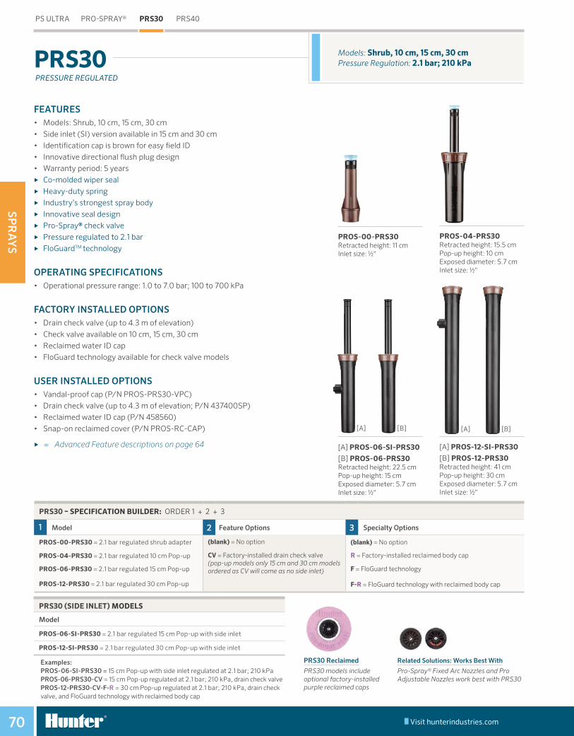
SPR
AY
S
Visit hunterindustries.com70
FEATURES• Models: Shrub, 10 cm, 15 cm, 30 cm• Side inlet (SI) version available in 15 cm and 30 cm• Identification cap is brown for easy field ID• Innovative directional flush plug design• Warranty period: 5 years
► Co-molded wiper seal ► Heavy-duty spring ► Industry’s strongest spray body ► Innovative seal design ► Pro-Spray® check valve ► Pressure regulated to 2.1 bar ► FloGuardTM technology
OPERATING SPECIFICATIONS• Operational pressure range: 1.0 to 7.0 bar; 100 to 700 kPa
FACTORY INSTALLED OPTIONS• Drain check valve (up to 4.3 m of elevation)• Check valve available on 10 cm, 15 cm, 30 cm• Reclaimed water ID cap• FloGuard technology available for check valve models
USER INSTALLED OPTIONS• Vandal-proof cap (P/N PROS-PRS30-VPC)• Drain check valve (up to 4.3 m of elevation; P/N 437400SP)• Reclaimed water ID cap (P/N 458560)• Snap-on reclaimed cover (P/N PROS-RC-CAP)
► = Advanced Feature descriptions on page 64
Models: Shrub, 10 cm, 15 cm, 30 cmPressure Regulation: 2.1 bar; 210 kPaPRS30
PRESSURE REGULATED
PS ULTRA PRO-SPRAY® PRS30 PRS40
PRS30 Reclaimed
PRS30 models include optional factory-installed purple reclaimed caps
Related Solutions: Works Best With
Pro-Spray® Fixed Arc Nozzles and Pro Adjustable Nozzles work best with PRS30
PRS30 – SPECIFICATION BUILDER: ORDER 1 + 2 + 3
1 Model 2 Feature Options 3 Specialty Options
PROS-00-PRS30 = 2.1 bar regulated shrub adapter (blank) = No option
CV = Factory-installed drain check valve (pop-up models only 15 cm and 30 cm models ordered as CV will come as no side inlet)
(blank) = No option
PROS-04-PRS30 = 2.1 bar regulated 10 cm Pop-up R = Factory-installed reclaimed body cap
PROS-06-PRS30 = 2.1 bar regulated 15 cm Pop-up F = FloGuard technology
PROS-12-PRS30 = 2.1 bar regulated 30 cm Pop-up F-R = FloGuard technology with reclaimed body cap
PRS30 (SIDE INLET) MODELS
Model
PROS-06-SI-PRS30 = 2.1 bar regulated 15 cm Pop-up with side inlet
PROS-12-SI-PRS30 = 2.1 bar regulated 30 cm Pop-up with side inlet
Examples: PROS-06-SI-PRS30 = 15 cm Pop-up with side inlet regulated at 2.1 bar; 210 kPa PROS-06-PRS30-CV = 15 cm Pop-up regulated at 2.1 bar; 210 kPa, drain check valve PROS-12-PRS30-CV-F-R = 30 cm Pop-up regulated at 2.1 bar; 210 kPa, drain check valve, and FloGuard technology with reclaimed body cap
[A] PROS-12-SI-PRS30
[B] PROS-12-PRS30Retracted height: 41 cmPop-up height: 30 cmExposed diameter: 5.7 cmInlet size: ½"
[A] PROS-06-SI-PRS30 [B] PROS-06-PRS30 Retracted height: 22.5 cmPop-up height: 15 cmExposed diameter: 5.7 cmInlet size: ½"
PROS-04-PRS30Retracted height: 15.5 cm Pop-up height: 10 cmExposed diameter: 5.7 cmInlet size: ½"
PROS-00-PRS30Retracted height: 11 cmInlet size: ½"
[A] [B] [A] [B]
Table of Contents:PRS30
Cross References:

SPR
AY
S
Visit hunterindustries.com 71RESIDENTIAL & COMMERCIAL IRRIGATION | Built on Innovation®
FEATURES• Models: Shrub, 10 cm, 15 cm, 30 cm• Grey identification cap for easy field ID• Innovative directional flush plug design• Drain check valve installed with up to 4.3 m of elevation comes standard• 15 cm and 30 cm models come standard as no side inlet, ensuring proper
installation with check valve• Warranty period: 5 years
► Co-molded wiper seal ► Heavy-duty spring ► Industry’s strongest spray body ► Innovative seal design ► Pro-Spray® check valve ► Pressure regulated to 2.8 bar ► FloGuardTM technology
OPERATING SPECIFICATIONS• Operational pressure range: 1.0 to 7.0 bar; 100 to 700 kPa
FACTORY INSTALLED OPTIONS• Reclaimed water ID cap• FloGuard technology available for check valve models
USER INSTALLED OPTIONS• Reclaimed water ID cap (P/N 458562) • Snap-on reclaimed cover (P/N PROS-RC-CAP)
► = Advanced Feature descriptions on page 64
Models: Shrub, 10 cm, 15 cm, 30 cmPressure Regulation: 2.8 bar; 280 kPaPRS40
PROS-00-PRS40Retracted height: 11 cmInlet size: ½"
PROS-04-PRS40-CVRetracted height: 15.5 cmPop-up height: 10 cmExposed diameter: 5.7 cmInlet size: ½"
PROS-06-PRS40-CVRetracted height: 22.5 cmPop-up height: 15 cmExposed diameter: 5.7 cmInlet size: ½"
PROS-12-PRS40-CVRetracted height: 41 cmPop-up height: 30 cmExposed diameter: 5.7 cmInlet size: ½"
PRS40 Reclaimed
PRS40 models include optional factory-installed purple reclaimed caps.
PRESSURE REGULATED
Related Solutions: MP Rotator
PRS40 is designed specifically for the MP Rotator.
PS ULTRA PRO-SPRAY® PRS30 PRS40
PRS40 – SPECIFICATION BUILDER: ORDER 1 + 2
1 Model 2 Specialty Options
PROS-00-PRS40 = 2.8 bar regulated shrub adapter
PROS-04-PRS40-CV = 2.8 bar regulated 10 cm Pop-up with drain check valve
PROS-06-PRS40-CV = 2.8 bar regulated 15 cm Pop-up with drain check valve
PROS-12-PRS40-CV = 2.8 bar regulated 30 cm Pop-up with drain check valve
(blank) = No option
R = Factory-installed reclaimed body cap
F = FloGuard technology
F-R = FloGuard technology with reclaimed body cap
Examples: PROS-04-PRS40-CV = 10 cm Pop-up regulated at 2.8 bar, drain check valve PROS-06-PRS40-CV-F = 15 cm Pop-up regulated at 2.8 bar, drain check valve, with FloGuard technology PROS-12-PRS40-CV-R = 30 cm Pop-up regulated at 2.8 bar, drain check valve, reclaimed body cap
Cross References:PRS40
Cross References:PRS40 - MP Rotator Ref
Residential Solutions

NO
ZZ
LES
72
NOZZLES
Table of Contents:Nozzles
Cross References:

NO
ZZ
LES
Visit hunterindustries.com 73RESIDENTIAL & COMMERCIAL IRRIGATION | Built on Innovation®
4A Nozzle Radius: 1.2 m
8A NozzleRadius: 2.4 m
12A NozzleRadius: 3.7 m
17A NozzleRadius: 5.2 m
6A NozzleRadius: 1.8 m
10A NozzleRadius: 3.0 m
15A NozzleRadius: 4.6 m
FEATURES• Crisp, well-defined edges• Matched precipitation rate on each nozzle from 8A to 17A• Easy grip top for simple adjustment• Large water droplets cut through wind• Even distribution results in better coverage• 1.2 m and 1.8 m models provide additional flexibility• Colour-coded for easy field identification• Adjustable from 0° to 360°
OPERATING SPECIFICATIONS• Recommended operating pressure: 2.1 bar and 210 kPa• Specify the Pro-Spray® PRS30 pop-up for accurate pressure
regulation of 2.1 bar; 210 kPa
PRO ADJUSTABLE NOZZLES
PRO ADJUSTABLE NOZZLES PRO-SPRAY® FIXED ARC NOZZLE SPECIALTY NOZZLE BUBBLERS
Cross References:Pro Adjustable Nozzles
Cross References:

NO
ZZ
LES
Visit hunterindustries.com74
PRO ADJUSTABLE NOZZLES PRO-SPRAY® FIXED ARC NOZZLE SPECIALTY NOZZLE BUBBLERS
4A
Lt. Green
1.2 m radius Adjustable from 0° to 360° Trajectory: 0°
Arc Pressure Radius m
Flow Precip mm/hr bar kPa m3/hr l/min
45°1.0 100 0.9 0.02 0.31 187 2161.5 150 1.0 0.02 0.39 178 206
2.1 210 1.2 0.03 0.48 167 1932.5 250 1.3 0.03 0.56 158 1833.0 300 1.4 0.04 0.64 149 172
90°1.0 100 0.9 0.02 0.31 93 1081.5 150 1.0 0.02 0.39 89 103
2.1 210 1.2 0.03 0.48 84 972.5 250 1.3 0.03 0.56 79 913.0 300 1.4 0.04 0.64 75 86
120°1.0 100 0.9 0.06 0.97 221 2551.5 150 1.0 0.07 1.10 188 217
2.1 210 1.2 0.07 1.25 162 1872.5 250 1.3 0.08 1.36 146 1683.0 300 1.4 0.09 1.49 131 151
180°1.0 100 0.9 0.07 1.18 178 2061.5 150 1.0 0.08 1.38 157 181
2.1 210 1.2 0.10 1.60 139 1602.5 250 1.3 0.11 1.78 127 1463.0 300 1.4 0.12 1.98 115 133
240°1.0 100 0.9 0.12 1.94 220 2541.5 150 1.0 0.13 2.24 192 221
2.1 210 1.2 0.16 2.59 168 1942.5 250 1.3 0.17 2.86 153 1773.0 300 1.4 0.19 3.17 139 160
270°1.0 100 0.9 0.13 2.09 211 2441.5 150 1.0 0.14 2.40 183 211
2.1 210 1.2 0.16 2.75 159 1832.5 250 1.3 0.18 3.02 144 1663.0 300 1.4 0.20 3.33 130 150
360°1.0 100 0.9 0.14 2.26 171 1971.5 150 1.0 0.16 2.60 148 171
2.1 210 1.2 0.18 2.98 129 1492.5 250 1.3 0.20 3.29 117 1353.0 300 1.4 0.22 3.63 106 122
Bold = Recommended pressure Note: The Pro-Spray PRS30’s built-in pressure regulator controls output to a maximum of 2.1 bar; 210 kPa. Adjusting the radius reduction screw may be required to achieve catalogue radius and flow.
6A
Lt. Blue
1.8 m radiusAdjustable from 0° to 360°Trajectory: 0°
Radius m
Flow Precip mm/hr m3/hr l/min
1.5 0.03 0.54 117 1361.6 0.04 0.60 108 124
1.8 0.04 0.65 98 1141.9 0.04 0.70 92 1062.1 0.05 0.75 86 99
1.5 0.06 1.08 116 1341.6 0.07 1.21 109 126
1.8 0.08 1.35 102 1181.9 0.09 1.47 97 1122.1 0.10 1.61 92 106
1.5 0.08 1.26 102 1181.6 0.09 1.43 97 112
1.8 0.10 1.61 91 1051.9 0.11 1.76 87 1002.1 0.12 1.93 82 95
1.5 0.10 1.70 92 1061.6 0.12 1.96 88 102
1.8 0.13 2.24 84 971.9 0.15 2.47 81 942.1 0.16 2.72 78 90
1.5 0.15 2.44 99 1141.6 0.17 2.83 96 111
1.8 0.20 3.28 92 1071.9 0.22 3.63 89 1032.1 0.24 4.03 86 99
1.5 0.18 3.08 111 1281.6 0.21 3.52 106 122
1.8 0.24 4.02 101 1161.9 0.27 4.42 97 1122.1 0.29 4.87 92 107
1.5 0.21 3.57 96 1111.6 0.24 4.07 92 106
1.8 0.28 4.62 87 1001.9 0.30 5.06 83 962.1 0.33 5.56 79 92
8A
Brown
2.4 m radiusAdjustable from 0° to 360°Trajectory: 0°
Radius m
Flow Precip mm/hr m3/hr l/min
2.0 0.04 0.62 77 892.2 0.04 0.72 72 83
2.4 0.05 0.83 67 772.6 0.05 0.91 63 732.9 0.06 1.01 59 68
2.0 0.07 1.24 77 892.2 0.09 1.44 72 83
2.4 0.10 1.65 67 772.6 0.11 1.82 63 732.9 0.12 2.02 59 68
2.0 0.10 1.66 77 892.2 0.11 1.92 72 83
2.4 0.13 2.20 67 772.6 0.15 2.43 63 732.9 0.16 2.69 59 68
2.0 0.15 2.49 77 892.2 0.17 2.87 72 83
2.4 0.20 3.30 67 772.6 0.22 3.65 63 732.9 0.24 4.03 59 68
2.0 0.20 3.32 77 892.2 0.23 3.83 72 83
2.4 0.26 4.40 67 772.6 0.29 4.86 63 732.9 0.32 5.38 59 68
2.0 0.22 3.73 77 892.2 0.26 4.31 72 83
2.4 0.30 4.95 67 772.6 0.33 5.47 63 732.9 0.36 6.05 59 68
2.0 0.30 4.97 77 892.2 0.34 5.75 72 83
2.4 0.40 6.61 67 772.6 0.44 7.29 63 732.9 0.48 8.07 59 68
PRO ADJUSTABLE NOZZLES PERFORMANCE DATA

NO
ZZ
LES
Visit hunterindustries.com 75RESIDENTIAL & COMMERCIAL IRRIGATION | Built on Innovation®
PRO ADJUSTABLE NOZZLES PRO-SPRAY® FIXED ARC NOZZLE SPECIALTY NOZZLE BUBBLERS
10A
Red
3.0 m radiusAdjustable from 0° to 360°Trajectory: 15°
Arc Pressure Radius m
Flow Precip mm/hr bar kPa m3/hr l/min
45°1.0 100 2.6 0.04 0.68 49 561.5 150 2.8 0.05 0.80 49 57
2.1 210 3.0 0.06 0.94 49 562.5 250 3.2 0.06 1.06 48 563.0 300 3.5 0.07 1.18 47 54
90°1.0 100 2.6 0.08 1.35 49 561.5 150 2.8 0.10 1.61 49 57
2.1 210 3.0 0.11 1.89 49 562.5 250 3.2 0.13 2.11 48 563.0 300 3.5 0.14 2.37 47 54
120°1.0 100 2.6 0.11 1.80 49 561.5 150 2.8 0.13 2.14 49 57
2.1 210 3.0 0.15 2.52 49 562.5 250 3.2 0.17 2.82 48 563.0 300 3.5 0.19 3.16 47 54
180°1.0 100 2.6 0.16 2.71 49 561.5 150 2.8 0.19 3.21 49 57
2.1 210 3.0 0.23 3.78 49 562.5 250 3.2 0.25 4.23 48 563.0 300 3.5 0.28 4.73 47 54
240°1.0 100 2.6 0.22 3.61 49 561.5 150 2.8 0.26 4.28 49 57
2.1 210 3.0 0.30 5.03 49 562.5 250 3.2 0.34 5.64 48 563.0 300 3.5 0.38 6.31 47 54
270°1.0 100 2.6 0.24 4.06 49 561.5 150 2.8 0.29 4.82 49 57
2.1 210 3.0 0.34 5.66 49 562.5 250 3.2 0.38 6.34 48 563.0 300 3.5 0.43 7.10 47 54
360°1.0 100 2.6 0.32 5.41 49 561.5 150 2.8 0.39 6.43 49 57
2.1 210 3.0 0.45 7.55 49 562.5 250 3.2 0.51 8.45 48 563.0 300 3.5 0.57 9.47 47 54
Bold = Recommended pressure Note: The Pro-Spray PRS30’s built-in pressure regulator controls output to a maximum of 2.1 bar; 210 kPa. Adjusting the radius reduction screw may be required to achieve catalogue radius and flow.
12A
Green
3.7 m radius Adjustable from 0° to 360° Trajectory: 28°
Radius m
Flow Precip mm/hr m3/hr l/min
3.2 0.04 0.73 34 403.4 0.06 0.97 40 46
3.7 0.07 1.23 44 513.9 0.09 1.44 46 544.1 0.10 1.68 48 56
3.2 0.09 1.46 34 403.4 0.12 1.93 40 46
3.7 0.15 2.46 44 513.9 0.17 2.88 46 544.1 0.20 3.36 48 56
3.2 0.12 1.94 34 403.4 0.15 2.58 40 46
3.7 0.20 3.28 44 513.9 0.23 3.84 46 544.1 0.27 4.48 48 56
3.2 0.17 2.91 34 403.4 0.23 3.86 40 46
3.7 0.30 4.92 44 513.9 0.35 5.76 46 544.1 0.40 6.71 48 56
3.2 0.23 3.88 34 403.4 0.31 5.15 40 46
3.7 0.39 6.56 44 513.9 0.46 7.68 46 544.1 0.54 8.95 48 56
3.2 0.26 4.37 34 403.4 0.35 5.80 40 46
3.7 0.44 7.38 44 513.9 0.52 8.65 46 544.1 0.60 10.07 48 56
3.2 0.35 5.83 34 403.4 0.46 7.73 40 46
3.7 0.59 9.84 44 513.9 0.69 11.53 46 544.1 0.81 13.43 48 56
15A
Black
4.6 m radiusAdjustable from 0° to 360°Trajectory: 28°
Radius m
Flow Precip mm/hr m3/hr l/min
4.0 0.08 1.27 38 434.3 0.09 1.51 39 45
4.6 0.11 1.79 40 464.9 0.12 2.00 40 465.2 0.14 2.25 40 46
4.0 0.15 2.53 38 434.3 0.18 3.03 39 45
4.6 0.21 3.57 40 464.9 0.24 4.01 40 465.2 0.27 4.50 40 46
4.0 0.20 3.38 38 434.3 0.24 4.03 39 45
4.6 0.29 4.76 40 464.9 0.32 5.34 40 465.2 0.36 6.00 40 46
4.0 0.30 5.07 38 434.3 0.36 6.05 39 45
4.6 0.43 7.14 40 464.9 0.48 8.02 40 465.2 0.54 9.00 40 46
4.0 0.41 6.76 38 434.3 0.48 8.07 39 45
4.6 0.57 9.52 40 464.9 0.64 10.69 40 465.2 0.72 12.00 40 46
4.0 0.46 7.60 38 434.3 0.54 9.08 39 45
4.6 0.64 10.71 40 464.9 0.72 12.03 40 465.2 0.81 13.50 40 46
4.0 0.61 10.13 38 434.3 0.73 12.10 39 45
4.6 0.86 14.28 40 464.9 0.96 16.03 40 465.2 1.08 18.00 40 46
PRO ADJUSTABLE NOZZLES PERFORMANCE DATA

NO
ZZ
LES
Visit hunterindustries.com76
Pro Adjustable Nozzle
PRO ADJUSTABLE NOZZLES PRO-SPRAY® FIXED ARC NOZZLE SPECIALTY NOZZLE BUBBLERS
PRO ADJUSTABLE NOZZLES PERFORMANCE DATA
17A
Grey
5.2 m radiusAdjustable from 0° to 360°Trajectory: 28°
Arc Pressure Radius m
Flow Precip mm/hr bar kPa m3/hr l/min
45°1.0 100 4.6 0.10 1.68 38 431.5 150 4.9 0.12 1.94 38 44
2.1 210 5.2 0.13 2.23 39 452.5 250 5.5 0.15 2.46 39 453.0 300 5.8 0.16 2.72 39 45
90°1.0 100 4.6 0.20 3.36 38 431.5 150 4.9 0.23 3.88 38 44
2.1 210 5.2 0.27 4.45 39 452.5 250 5.5 0.30 4.92 39 453.0 300 5.8 0.33 5.44 39 45
120°1.0 100 4.6 0.27 4.48 38 431.5 150 4.9 0.31 5.17 38 44
2.1 210 5.2 0.36 5.94 39 452.5 250 5.5 0.39 6.56 39 453.0 300 5.8 0.43 7.25 39 45
180°1.0 100 4.6 0.40 6.71 38 431.5 150 4.9 0.47 7.75 38 44
2.1 210 5.2 0.53 8.91 39 452.5 250 5.5 0.59 9.83 39 453.0 300 5.8 0.65 10.87 39 45
240°1.0 100 4.6 0.54 8.95 38 431.5 150 4.9 0.62 10.34 38 44
2.1 210 5.2 0.71 11.88 39 452.5 250 5.5 0.79 13.11 39 453.0 300 5.8 0.87 14.50 39 45
270°1.0 100 4.6 0.60 10.07 38 431.5 150 4.9 0.70 11.63 38 44
2.1 210 5.2 0.80 13.36 39 452.5 250 5.5 0.89 14.75 39 453.0 300 5.8 0.98 16.31 39 45
360°1.0 100 4.6 0.81 13.43 38 431.5 150 4.9 0.93 15.51 38 44
2.1 210 5.2 1.07 17.82 39 452.5 250 5.5 1.18 19.67 39 453.0 300 5.8 1.30 21.75 39 45
Bold = Recommended pressure Note: The Pro-Spray PRS30’s built-in pressure regulator controls output to a maximum of 2.1 bar; 210 kPa. Adjusting the radius reduction screw may be required to achieve catalogue radius and flow.

NO
ZZ
LES
Visit hunterindustries.com 77RESIDENTIAL & COMMERCIAL IRRIGATION | Built on Innovation®
FEATURES• Colour-coded for easy field identification• Optimum droplet size minimises misting while maximising uniformity
OPERATING SPECIFICATIONS• Recommended operating pressure: 2.1 bar; 210 kPa• Specify the Pro-Spray® PRS30 pop-up for accurate pressure regulation of 2.1 bar; 210 kPa
PRO-SPRAY® FIXED ARC NOZZLES
PRO ADJUSTABLE NOZZLES PRO-SPRAY® FIXED ARC NOZZLE SPECIALTY NOZZLE BUBBLERS
PRO-SPRAY® FIXED ARC NOZZLES
ARC 5 8 10 12 15 17
Q
T Use 4A/6A Nozzle
Use 17A Nozzle
H
TT Use 4A/6A Nozzle
Use 8A Nozzle
Use 10A Nozzle
Use 17A Nozzle
TQ Use 4A/6A Nozzle
Use 8A Nozzle
Use 10A Nozzle
Use 17A Nozzle
F Use 17A Nozzle
(1.5 m) (2.4 m) (3.0 m) (3.7 m) (4.6 m) (5.2 m)
Cross References:Pro-Spray® Fixed Arc Nozzles
Cross References:

NO
ZZ
LES
Visit hunterindustries.com78
PRO ADJUSTABLE NOZZLES PRO-SPRAY® FIXED ARC NOZZLE SPECIALTY NOZZLE BUBBLERS
5
Blue
1.5 m radiusFixed: ¼, ½, FullTrajectory: 0°
Arc Position Pressure Radius m
Flow Precip mm/hr bar kPa m3/hr l/min
90° Q1.0 100 1.1 0.02 0.30 60 691.5 150 1.3 0.02 0.38 54 62
2.0 200 1.5 0.03 0.45 48 55
2.1 210 1.5 0.03 0.46 49 572.5 250 1.7 0.03 0.51 42 49
120° T1.0 100
Use 4A or 6A Nozzle1.5 150
2.0 200
2.1 2102.5 250
180° H1.0 100 1.1 0.04 0.60 60 691.5 150 1.3 0.05 0.76 54 62
2.0 200 1.5 0.05 0.90 48 55
2.1 210 1.5 0.06 0.92 49 572.5 250 1.7 0.06 1.02 42 49
240° TT1.0 100
Use 4A or 6A Nozzle1.5 150
2.0 200
2.1 2102.5 250
270° TQ1.0 100
Use 4A or 6A Nozzle1.5 150
2.0 200
2.1 2102.5 250
360° F1.0 100 1.1 0.07 1.20 60 691.5 150 1.3 0.09 1.52 54 62
2.0 200 1.5 0.11 1.79 48 55
2.1 210 1.5 0.11 1.85 49 572.5 250 1.7 0.12 2.04 42 49
Bold = Recommended pressure
PRO-SPRAY® FIXED ARC NOZZLES PERFORMANCE DATA
8
Brown
2.4 m radiusFixed: ¼, ⅓, ½, FullTrajectory: 0°
Radius m
Flow Precip mm/hr m3/hr l/min
1.7 0.04 0.62 51 592.1 0.05 0.84 46 53
2.4 0.06 1.00 42 48
2.4 0.06 1.03 43 492.7 0.07 1.13 37 43
1.7 0.05 0.83 51 592.1 0.07 1.12 46 53
2.4 0.08 1.33 42 48
2.4 0.08 1.37 43 492.7 0.09 1.51 37 43
1.7 0.08 1.33 55 642.1 0.10 1.69 46 53
2.4 0.12 1.99 42 48
2.4 0.12 2.05 43 492.7 0.14 2.27 37 43
Use 8A Nozzle
Use 8A Nozzle
1.7 0.16 2.67 55 642.1 0.20 3.37 46 53
2.4 0.24 3.99 42 48
2.4 0.25 4.10 43 492.7 0.27 4.54 37 43
10
Red
3.0 m radiusFixed: ¼, ⅓, ½, FullTrajectory: 15°
Radius m
Flow Precip mm/hr m3/hr l/min
2.4 0.07 1.08 45 522.7 0.08 1.33 44 50
3.0 0.09 1.53 41 47
3.0 0.09 1.57 42 483.3 0.10 1.71 38 44
2.4 0.09 1.44 45 522.7 0.11 1.77 44 50
3.0 0.12 2.04 41 47
3.0 0.13 2.09 42 483.3 0.14 2.28 38 44
2.4 0.13 2.17 45 522.7 0.16 2.65 44 50
3.0 0.18 3.06 41 47
3.0 0.19 3.14 42 483.3 0.21 3.43 38 44
Use 10A Nozzle
Use 10A Nozzle
2.4 0.26 4.33 45 522.7 0.32 5.31 44 50
3.0 0.37 6.13 41 47
3.0 0.38 6.28 42 483.3 0.41 6.85 38 44

NO
ZZ
LES
Visit hunterindustries.com 79RESIDENTIAL & COMMERCIAL IRRIGATION | Built on Innovation®
PRO ADJUSTABLE NOZZLES PRO-SPRAY® FIXED ARC NOZZLE SPECIALTY NOZZLE BUBBLERS
12
Green
3.7 m radiusFixed: ¼, ⅓, ½, ⅔, ¾, FullTrajectory: 28°
Arc Position Pressure Radius m
Flow Precip mm/hr bar kPa m3/hr l/min
90° Q1.0 100 3.0 0.10 1.58 42 491.5 150 3.4 0.12 2.00 42 48
2.0 200 3.7 0.14 2.37 41 48
2.1 210 3.7 0.15 2.43 43 492.5 250 4.0 0.16 2.69 40 47
120° T1.0 100 3.0 0.13 2.11 42 491.5 150 3.4 0.16 2.67 42 48
2.0 200 3.7 0.19 3.16 41 48
2.1 210 3.7 0.19 3.25 43 492.5 250 4.0 0.22 3.59 40 47
180° H1.0 100 3.0 0.19 3.17 42 491.5 150 3.4 0.24 4.01 42 48
2.0 200 3.7 0.28 4.73 41 48
2.1 210 3.7 0.29 4.87 43 492.5 250 4.0 0.32 5.39 40 47
240° TT1.0 100 3.0 0.25 4.22 42 491.5 150 3.4 0.32 5.34 42 48
2.0 200 3.7 0.38 6.31 41 48
2.1 210 3.7 0.39 6.49 43 492.5 250 4.0 0.43 7.18 40 47
270° TQ1.0 100 3.0 0.29 4.75 42 491.5 150 3.4 0.36 6.01 42 48
2.0 200 3.7 0.43 7.10 41 48
2.1 210 3.7 0.44 7.30 43 492.5 250 4.0 0.48 8.08 40 47
360° F1.0 100 3.0 0.38 6.33 42 491.5 150 3.4 0.48 8.01 42 48
2.0 200 3.7 0.57 9.47 41 48
2.1 210 3.7 0.58 9.74 43 492.5 250 4.0 0.65 10.78 40 47
Bold = Recommended pressure
PRO-SPRAY® FIXED ARC NOZZLES PERFORMANCE DATA
15
Black
4.6 m radiusFixed: ¼, ⅓, ½, ⅔, ¾, FullTrajectory: 28°
Radius m
Flow Precip mm/hr m3/hr l/min
3.9 0.15 2.50 39 464.2 0.18 3.06 42 48
4.6 0.21 3.54 40 46
4.6 0.22 3.62 41 474.9 0.24 3.95 40 46
3.9 0.20 3.33 39 464.2 0.24 4.08 42 48
4.6 0.28 4.71 40 46
4.6 0.29 4.83 41 474.9 0.32 5.27 40 46
3.9 0.30 5.00 39 464.2 0.37 6.12 42 48
4.6 0.42 7.07 40 46
4.6 0.43 7.25 41 474.9 0.47 7.91 40 46
3.9 0.40 6.67 39 464.2 0.49 8.16 42 48
4.6 0.57 9.43 40 46
4.6 0.58 9.66 41 474.9 0.63 10.54 40 46
3.9 0.45 7.50 39 464.2 0.55 9.19 42 48
4.6 0.64 10.61 40 46
4.6 0.65 10.87 41 474.9 0.71 11.86 40 46
3.9 0.60 10.00 39 464.2 0.73 12.25 42 48
4.6 0.85 14.14 40 46
4.6 0.87 14.49 41 474.9 0.95 15.81 40 46
17
Grey
5.2 m radiusFixed: ¼, ½Trajectory: 28°
Radius m
Flow Precip mm/hr m3/hr l/min
4.7 0.19 3.17 34 404.9 0.23 3.88 39 45
5.2 0.27 4.48 40 46
5.2 0.28 4.59 41 475.5 0.30 5.01 40 46
Use 17A Nozzle
4.7 0.38 6.33 34 404.9 0.47 7.76 39 45
5.2 0.54 8.96 40 46
5.2 0.55 9.18 41 475.5 0.60 10.01 40 46
Use 17A Nozzle
Use 17A Nozzle
Use 17A Nozzle

NO
ZZ
LES
Visit hunterindustries.com80
FEATURES• Specifically designed for controlled irrigation of close-in spaces• Built to last in harsh conditions• Available in 0.6 m, 1.2 m and 1.8 m radius versions
SHORT RADIUS NOZZLES
2Q NozzleRadius: 0.6 m
4Q NozzleRadius: 1.2 m
6Q NozzleRadius: 1.8 m
2H NozzleRadius: 0.6 m
4H NozzleRadius: 1.2 m
6H NozzleRadius: 1.8 m
PRO ADJUSTABLE NOZZLES PRO-SPRAY® FIXED ARC NOZZLE SPECIALTY NOZZLE BUBBLERS
SHORT RADIUS NOZZLES PERFORMANCE DATA
Nozzle Lt. Brown
Arc Pressure Position Radius m
Flow Precip mm/hr bar kPa m3/hr l/min
90°1.0 100
2Q 0.6 0.01 0.23 153 177
1.5 150 0.6 0.02 0.28 188 217
2.0 200 0.6 0.02 0.33 217 250
2.1 210 0.6 0.02 0.33 222 2572.5 250 0.6 0.02 0.36 242 280
180°1.0 100
2H 0.6 0.03 0.46 153 177
1.5 150 0.6 0.03 0.56 188 217
2.0 200 0.6 0.04 0.65 217 250
2.1 210 0.6 0.04 0.67 222 2572.5 250 0.6 0.04 0.73 242 280
Nozzle Lt. Green
Position Radius m
Flow Precip mm/hr m3/hr l/min
4Q 1.2 0.04 0.69 115 1331.2 0.05 0.77 128 147
1.2 0.05 0.82 137 158
1.2 0.05 0.84 139 1601.2 0.05 0.87 145 168
4H 1.2 0.08 1.39 115 1331.2 0.09 1.54 128 147
1.2 0.10 1.65 137 158
1.2 0.10 1.67 139 1601.2 0.10 1.74 145 168
Nozzle Lt. Blue
Position Radius m
Flow Precip mm/hr m3/hr l/min
6Q 1.8 0.11 1.84 136 1571.8 0.11 1.93 143 165
1.8 0.12 2.00 148 171
1.8 0.12 2.01 149 1721.8 0.22 2.06 152 176
6H 1.8 0.22 3.67 136 1571.8 0.22 3.86 143 165
1.8 0.22 4.00 148 171
1.8 0.22 4.03 149 1721.8 0.23 4.12 152 176
Arc Pressurebar kPa
90°1.0 1001.5 150
2.0 200
2.1 2102.5 250
180°1.0 1001.5 150
2.0 200
2.1 2102.5 250
Arc Pressurebar kPa
90°1.0 1001.5 150
2.0 200
2.1 2102.5 250
180°1.0 1001.5 150
2.0 200
2.1 2102.5 250
Bold = Recommended pressure
Table of Contents:Short Radius Nozzles
Cross References:

NO
ZZ
LES
Visit hunterindustries.com 81RESIDENTIAL & COMMERCIAL IRRIGATION | Built on Innovation®
FEATURES• Specifically designed for accurate coverage of strip areas• Available in an array of models built to water unique spaces• Built to last in harsh conditions
STRIP PATTERN NOZZLES
Left Corner StripRectangle: 1.5 m x 4.5 m
Side StripRectangle: 1.5 m x 9.1 m
Side StripRectangle: 2.7 m x 5.5 m
End StripRectangle: 1.5 m x 4.5 m
Center StripRectangle: 1.5 m x 9.1 m
Right Corner StripRectangle: 1.5 m x 4.5 m
PRO ADJUSTABLE NOZZLES PRO-SPRAY® FIXED ARC NOZZLE SPECIALTY NOZZLE BUBBLERS
STRIP PATTERN NOZZLE PERFORMANCE DATA
Arc Pressure Width x Length Flowbar kPa m m3/hr l/min
LCS-5151.0 100 1.2 x 4.2 0.10 1.71.5 150 1.2 x 4.3 0.13 2.1
2.0 200 1.5 x 4.5 0.15 2.4
2.1 210 1.5 x 4.5 0.15 2.52.5 250 1.5 x 4.5 0.16 2.7
RCS-5151.0 100 1.2 x 4.2 0.10 1.71.5 150 1.2 x 4.3 0.13 2.1
2.0 200 1.5 x 4.5 0.15 2.4
2.1 210 1.5 x 4.5 0.15 2.52.5 250 1.5 x 4.5 0.16 2.7
SS-5301.0 100 1.2 x 8.5 0.21 3.51.5 150 1.5 x 9.0 0.25 4.2
2.0 200 1.5 x 9.0 0.29 4.9
2.1 210 1.5 x 9.1 0.30 5.02.5 250 1.5 x 9.1 0.33 5.5
SS-9181.0 100 2.4 x 5.2 0.27 4.51.5 150 2.7 x 5.5 0.33 5.5
2.0 200 2.7 x 5.5 0.38 6.4
2.1 210 2.7 x 5.5 0.39 6.52.5 250 2.7 x 5.5 0.43 7.1
CS-5301.0 100 1.2 x 8.5 0.21 3.51.5 150 1.5 x 9.0 0.25 4.2
2.0 200 1.5 x 9.0 0.29 4.9
2.1 210 1.5 x 9.1 0.30 5.02.5 250 1.5 x 9.1 0.33 5.5
ES-5151.0 100 1.1 x 4.2 0.10 1.71.5 150 1.2 x 4.3 0.13 2.1
2.0 200 1.5 x 4.5 0.15 2.4
2.1 210 1.5 x 4.5 0.15 2.52.5 250 1.5 x 4.5 0.16 2.7
Bold = Recommended pressure
Cross References:Strip Pattern Nozzles
Cross References:

NO
ZZ
LES
Visit hunterindustries.com82
FEATURES• Adjustable Arc from 25°-360°• Offered in 2 adjustable radius options• Lower application rate to avoid runoff• Multiple streams provide even coverage
STREAM NOZZLES
S-8ARadius: 2.1 m to 2.6 m
S-16ARadius: 4.3 m to 5.3 m
S-8A
STREAM NOZZLES
PRO ADJUSTABLE NOZZLES PRO-SPRAY® FIXED ARC NOZZLE SPECIALTY NOZZLE BUBBLERS
MODEL S-8A STREAM SPRAY NOZZLE PERFORMANCE DATA
Arc Pressure Radius m
Flow Precip mm/hr bar kPa m3/hr l/min
90°1.0 100 2.1 0.05 0.9 52 601.5 150 2.2 0.07 1.1 55 64
2.0 200 2.4 0.08 1.4 57 66
2.1 210 2.4 0.09 1.4 57 662.5 250 2.6 0.10 1.6 58 67
180°1.0 100 2.1 0.12 1.9 55 631.5 150 2.2 0.13 2.1 51 58
2.0 200 2.4 0.14 2.3 47 54
2.1 210 2.4 0.14 2.3 46 532.5 250 2.6 0.15 2.4 44 50
360°1.0 100 2.1 0.24 4.0 56 651.5 150 2.2 0.25 4.2 50 58
2.0 200 2.4 0.26 4.4 45 52
2.1 210 2.4 0.26 4.4 44 512.5 250 2.6 0.27 4.6 41 47
Bold = Recommended pressure
MODEL S-16A STREAM SPRAY NOZZLE PERFORMANCE DATA
Arc Pressure Radius m
Flow Precip mm/hr bar kPa m3/hr l/min
90°1.0 100 4.3 0.08 1.4 18 211.5 150 4.6 0.10 1.6 18 21
2.0 200 5.0 0.11 1.9 18 21
2.1 210 5.0 0.11 1.9 18 212.5 250 5.3 0.13 2.1 18 21
180°1.0 100 4.3 0.14 2.3 14 171.5 150 4.6 0.17 2.8 15 18
2.0 200 5.0 0.20 3.3 16 18
2.1 210 5.0 0.20 3.4 16 192.5 250 5.3 0.23 3.8 16 19
360°1.0 100 4.3 0.23 3.9 12 141.5 150 4.6 0.30 5.0 14 16
2.0 200 5.0 0.36 6.1 15 17
2.1 210 5.0 0.38 6.3 15 172.5 250 5.3 0.43 7.2 16 18
Bold = Recommended pressure
Table of Contents:Stream Nozzles
Cross References:

NO
ZZ
LES
Visit hunterindustries.com 83RESIDENTIAL & COMMERCIAL IRRIGATION | Built on Innovation®
FEATURES• Pressure compensation ensures uniform output across various pressures• Provides the correct amount of water, reducing runoff or waste• Nozzle threaded for use with Pro-Spray®
BUBBLER NOZZLES
MSBN-25QFlow: 0.06 m3/hr; 0.9 l/min
MSBN-10H/10FFlow: 0.23 m3/hr; 3.8 l/min
MSBN-20FFlow: 0.45 m3/hr; 7.6 l/min
PCN-50Flow: 0.11 m3/hr; 1.9 l/min
PCN-20Flow: 0.46 m3/hr; 7.6 l/min
PCN-25Flow: 0.06 m3/hr; 0.9 l/min
PCN-10Flow: 0.23 m3/hr; 3.8 l/min
MSBN-50Q/50HFlow: 0.11 m3/hr; 1.9 l/min
MULTI-STREAM BUBBLER NOZZLES
PRESSURE COMPENSATING BUBBLER NOZZLES
Multi-Stream Bubbler
PCN
PRO ADJUSTABLE NOZZLES PRO-SPRAY® FIXED ARC NOZZLE SPECIALTY NOZZLE BUBBLERS
MSBN Installed on PROS-04
Combining Hunter Bubbler Nozzles with the Pro-Spray provides the watering precision of pressure compensating bubblers paired with the benefit of retracting the nozzle out of sight.
MULTI-STREAM BUBBLER PERFORMANCE DATA
Arc Model Flow Radiusmm3/hr l/min
MSBN-25Q 0.06 0.9 0.30
MSBN-50Q 0.11 1.9 0.46
MSBN-50H 0.11 1.9 0.30
MSBN-10H 0.23 3.8 0.46
MSBN-10F 0.23 3.8 0.30
MSBN-20F 0.45 7.6 0.46
Notes:Typical spacing 0.6 to 1.2 m. Flows shown for pressures between 1.0 and 4.8 bar; 100 and 480 kPa.
PCN PERFORMANCE DATA
Model Flow Pattern Typem3/hr l/min
25 0.06 0.9 Trickle50 0.11 1.9 Trickle
10 0.23 3.8 Umbrella
20 0.46 7.6 Umbrella
Notes:Typical spacing 0.3 to 0.9 m. Flows shown for pressures between 1.0 and 4.8 bar; 100 and 480 kPa.
Cross References:Bubbler Nozzles
Cross References:

NO
ZZ
LES
Visit hunterindustries.com84
FEATURES• Pressure compensation ensures uniform output across various pressures• ½" inlet• Flow marked top for easy identification
BUBBLERS
PCB
AFB
5-CST-B
PCB-R
PRESSURE COMPENSATING BUBBLERS
DUAL-STREAM BUBBLER NOZZLE
ADJUSTABLE FLOOD BUBBLER
PCB
AFB
5-CST-B
PRO ADJUSTABLE NOZZLES PRO-SPRAY® FIXED ARC NOZZLE SPECIALTY NOZZLE BUBBLERS
PCB PERFORMANCE DATA
Model Flow Pattern Typem3/hr l/min
25 0.06 0.9 Trickle50 0.11 1.9 Trickle
10 0.23 3.8 Umbrella20 0.45 7.6 Umbrella
Notes:Typical spacing 0.6 to 1.2 m. Flows shown for pressures between 1.0 and 4.8 bar; 100 and 480 kPa.
AFB PERFORMANCE DATA
Model Flow Pattern Typem3/hr l/min
AFB < 0.45 < 7.6 Trickle/Umbrella
5-CST-B BUBBLER NOZZLE PERFORMANCE DATA
Pressure Radiusm
Flowbar kPa m3/hr l/min
1.0 100 1.5 0.07 1.11.5 150 1.5 0.07 1.22.0 200 1.5 0.09 1.42.1 210 1.5 0.09 1.52.5 250 1.5 0.10 1.6
Table of Contents:Bubblers
Cross References:

NO
ZZ
LES
85
Built to LastHUNTER SPRAY NOZZLES
SPRAY BODIES:
Always Perform Under PressureWith an industry-leading 34.5 bar; 3,450 kPa burst pressure, the Pro-Spray® is built to perform in the most demanding irrigation systems in the world.
Innovative Seal Design Prevents LeaksMost spray bodies leak when the cap is loosened only a quarter turn. The Pro-Spray can handle over one full turn of the cap with no leak or loss of performance.
SPRAY NOZZLES:
Designed for Complete CoverageThe industry’s strongest edges and uniformcoverage at full radius means no section oflandscape is missed.
Thick Droplets Get the Job Done RightHunter spray nozzles disperse the largest water droplets of any spray nozzle on the market, so water is not deflected by wind or held back by thick turf.

VALV
ES
86
Table of Contents:Valves
Cross References:

VALV
ES
87
VALVESSECTION 04:

VALV
ES
88
ACCU SYNC® PRESSURE REGULATION
FILTER SENTRY™
NEW RECLAIMED ICV VALVE
FLOW CONTROL
Available on:
PGV, ICV, IBV
Available on:
ICV, IBV
Available on:
PGV, ICV, IBV
Avoid sprinkler over-pressure conditions and experience significant water savings with Hunterʼs Accu Sync pressure regulator. This option is available in adjustable pressure or fixed pressure models.
Filter Sentry disk scours the filter clean twice during each valve cycle. Since it is attached to the diaphragm, the Filter Sentry feature can be easily added after a valve has been installed.
The ICV-R reclaimed water valve is constructed with ultra-durable, chlorine-resistant materials and maintains top performance in reclaimed water installations.
Maximise efficiency and prolong the life of a system by fine tuning flow and pressure for each zone.
VALVESADVANCED FEATURESDURABLE & RELIABLE
RECLAIMED WATER IDENTIFICATION
Available on:
PGV, ICV, IBV
Purple tags and handles are an option for a clear, quick, and simple method of identifying the use of non-potable water.
Table of Contents:
Cross References:Valves - Advanced Features
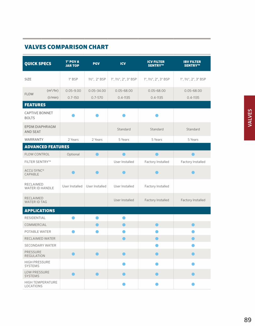
VALV
ES
89
VALVES COMPARISON CHART
QUICK SPECS 1" PGV & JAR TOP PGV ICV ICV FILTER
SENTRY™IBV FILTER SENTRY™
SIZE 1" BSP 1½", 2" BSP 1", 1½", 2", 3" BSP 1", 1½", 2", 3" BSP 1", 1½", 2", 3" BSP
FLOW(m3/hr) 0.05–9.00 0.05–34.00 0.05–68.00 0.05–68.00 0.05–68.00
(l/min) 0.7-150 0.7-570 0.4-1135 0.4-1135 0.4-1135
FEATURES
CAPTIVE BONNET BOLTS
⬤ ⬤ ⬤ ⬤
EPDM DIAPHRAGM AND SEAT
Standard Standard Standard
WARRANTY 2 Years 2 Years 5 Years 5 Years 5 Years
ADVANCED FEATURES
FLOW CONTROL Optional ⬤ ⬤ ⬤ ⬤
FILTER SENTRY™ User Installed Factory Installed Factory Installed
ACCU SYNC® CAPABLE ⬤ ⬤ ⬤ ⬤ ⬤
RECLAIMED WATER ID HANDLE User Installed User Installed User Installed Factory Installed
RECLAIMED WATER ID TAG User Installed Factory Installed Factory Installed
APPLICATIONS
RESIDENTIAL ⬤ ⬤ ⬤
COMMERCIAL ⬤ ⬤ ⬤ ⬤
POTABLE WATER ⬤ ⬤ ⬤ ⬤ ⬤
RECLAIMED WATER ⬤ ⬤ ⬤
SECONDARY WATER ⬤ ⬤
PRESSURE REGULATION ⬤ ⬤ ⬤ ⬤ ⬤
HIGH PRESSURE SYSTEMS ⬤ ⬤ ⬤
LOW PRESSURE SYSTEMS ⬤ ⬤ ⬤ ⬤ ⬤
HIGH TEMPERATURE LOCATIONS ⬤ ⬤ ⬤

Visit hunterindustries.com90
VALV
ES
PGV-100G Inlet Diameter: 1" (25 mm)Height: 13 cm Length: 11 cm Width: 6 cm
PGV-101G Inlet Diameter: 1" (25 mm)Height: 13 cm Length: 11 cm Width: 6 cm
FEATURES• Size: 1" (25 mm)• External and internal manual bleed allows quick and easy
“at the valve” activation• Double-beaded diaphragm seal design for superior leak-free
performance• Durable glass-filled nylon threaded bonnet ring allows easy
access without tools (Jar Top)• Optional: DC latching solenoids enable Hunter’s
battery-powered controllers• Captive bonnet bolts provide hassle-free valve maintenance• Low flow capability allows use of Hunter’s micro-irrigation products• Encapsulated 24 VAC solenoid with captive plunger for
hassle-free service• Temperature rating: 66° C• Warranty period: 2 years
► Flow control ► Accu Sync® pressure regulation ► Optional reclaimed water ID
OPERATING SPECIFICATIONS• Flow: 0.05 to 9 m3/hr; 0.7 to 150 l/min• Recommended pressure range: 1.5 to 10 bar; 150 to 1,000 kPa
SOLENOID SPECIFICATIONS• 24 VAC solenoid
- 350 mA inrush, 190 mA holding, 60 Hz - 370 mA inrush, 210 mA holding, 50 Hz
FACTORY INSTALLED OPTIONS• Valve without solenoid• DC latching solenoid
USER INSTALLED OPTIONS• Solenoid conduit cover (P/N 464322)• DC latching solenoid (P/N 458200)• Accu Sync pressure regulator*• Reclaimed water ID handle for PGV-101 models (P/N 269205)
► = Advanced Feature descriptions on page 88
* Accu Sync product information on page 100
Inlet: 1" (25 mm)Flow: 0.05 to 9 m³/hr; 0.7 to 150 l/min1" PGV & PGV JAR TOP
PGV-100JT-GInlet Diameter: 1" (25 mm)Height: 14 cm Length: 11 cm Width: 8 cm
PGV-101JT-GInlet Diameter: 1" (25 mm)Height: 14 cm Length: 11 cm Width: 8 cm
PGV Jar Top
1" PGV & PGV JAR TOP PGV ICV IBV QUICK COUPLERS ACCU SYNC®
Table of Contents:1" PGV and PGV Jar Top
Cross References:

Visit hunterindustries.com 91
VALV
ES
RESIDENTIAL & COMMERCIAL IRRIGATION | Built on Innovation®
PGV-100G Installed
1" PGV & PGV JAR TOP PGV ICV IBV QUICK COUPLERS ACCU SYNC®
PGV 1" – SPECIFICATION BUILDER: ORDER 1 + 2 + 3 + 4
1 Model 2 Inlet/Outlet 3 Options (Factory Installed) 4 Options (User Installed)
PGV-100G = 1" (25 mm) Globe valve, without flow control
PGV-101G = 1" (25 mm) Globe valve, with flow control
PGV-100A = 1" (25 mm) Angle valve, without flow control
PGV-101A = 1" (25 mm) Angle valve, with flow control
(blank) = NPT threads (blank) = No Option (blank) = No option
B = BSP threads DC = DC latching solenoidR = Reclaimed water ID handle (Except for PGV-100)LS = Valve without solenoid
CC = Solenoid conduit cover
DC = DC latching solenoid
AS-ADJ = Accu Sync® adjustable pressure regulatorPGV-100 = 1" (25 mm) Globe valve, without flow control
MM = Male x male (NPT)
PGV-101 = 1" (25 mm) Globe valve, with flow control
MMB = Male x male (BSP) AS-xx* = Accu Sync pressure regulator20 * = 1.4 bar, 30 * = 2.1 bar, 40 * = 2.8 bar 50 * = 3.5 bar, 70 * = 4.8 bar
Example: PGV-101G - B - DC = 1" (25 mm) Globe valve, with flow control, BSP threads, and DC latching solenoid
PGV JAR TOP – SPECIFICATION BUILDER: ORDER 1 + 2 + 3 + 4
1 Model 2 Inlet/Outlet 3 Options (Factory Installed) 4 Options (User Installed)
PGV-100JT = 1" (25 mm) Globe jar top valve, without flow control
GB = BSP threads (blank) = No option (blank) = No option
MM = Male x male (NPT) LS = Less solenoid
DC = DC latching solenoid
R = Reclaimed water ID handle (Except for PGV-100JT)
PGV-101JT = 1" (25 mm) Globe jar top valve, with flow control
MMB = Male x male (BSP)
CC = Solenoid conduit cover
DC = DC latching solenoid
AS-ADJ = Accu Sync adjustable pressure regulator
AS-xx* = Accu Sync pressure regulator20 * = 1.4 bar, 30 * = 2.1 bar, 40 * = 2.8 bar 50 * = 3.5 bar, 70 * = 4.8 bar
Examples: PGV-100JT-GB = 1" (25 mm) Globe jar top valve, without flow control, and BSP threads PGV-100JT-MMB = 1" (25 mm) Globe jar top valve, without flow control, and male BSP threads
1" (25 MM) PGV VALVE
Flow l/min
Pressure Loss kPa
4 8
20 11
40 13
55 16
75 23
95 43
115 62
135 110150 148
1" (25 MM) PGV VALVE
Flow m3/hr
Pressure Loss bar
0.3 0.08
1.0 0.11
2.5 0.13
3.5 0.16
4.5 0.23
5.5 0.43
6.5 0.62
8.0 1.109.0 1.48

Visit hunterindustries.com92
VALV
ES
FEATURES• Sizes: 1½" (40 mm), 2" (50 mm)• External and internal manual bleed allows quick and easy
“at the valve” activation• Double-beaded diaphragm seal design assures leak-free performance• Optional: DC latching solenoids enable Hunter’s battery-powered controllers• Captive bonnet bolts provide hassle-free valve maintenance• Encapsulated 24 VAC solenoid with captive plunger for hassle-free service• Temperature rating: 66° C• Warranty period: 2 years
► Flow control ► Accu Sync® pressure regulation ► Optional reclaimed water ID handle
OPERATING SPECIFICATIONS• Flow:
- PGV-151: 5 to 27 m3/hr; 75 to 450 l/min - PGV-201: 5 to 34 m3/hr; 75 to 570 l/min
• Recommended pressure range: 1.5 to 10 bar; 150 to 1000 kPa
SOLENOID SPECIFICATIONS• 24 VAC solenoid
- 350 mA inrush, 190 mA holding, 60 Hz - 370 mA inrush, 210 mA holding, 50 Hz
FACTORY INSTALLED OPTIONS• Valve without solenoid• DC latching solenoid
USER INSTALLED OPTIONS• Solenoid conduit cover (P/N 464322)• DC latching solenoid (P/N 458200)• Accu Sync pressure regulator• Reclaimed water ID (P/N 607105)
► = Advanced Feature descriptions on page 88
Inlet: 1½" (40 mm), 2" (50 mm) Flow: 5 to 34 m³/hr; 75 to 570 l/minPGV
PGV-151Inlet Diameter: 1½" (40 mm)Height: 19 cm Length: 15 cm Width: 11 cm
PGV-201 Inlet Diameter: 2" (50 mm)Height: 20 cm Length: 17 cm Width: 13 cm
PGV Installed
1" PGV & PGV JAR TOP PGV ICV IBV QUICK COUPLERS ACCU SYNC®
Table of Contents:PGV
Cross References:

Visit hunterindustries.com 93
VALV
ES
RESIDENTIAL & COMMERCIAL IRRIGATION | Built on Innovation®
1" PGV & PGV JAR TOP PGV ICV IBV QUICK COUPLERS ACCU SYNC®
Filter Sentry
PGV 1.5" & 2" – SPECIFICATION BUILDER: ORDER 1 + 2 + 3 + 4
1 Model 2 Inlet/Outlet 3 Options (Factory Installed) 4 Options (User Installed)
PGV-151 = 1½" (40 mm) Globe/angle valve, with flow control
PGV-201 = 2" (50 mm) Globe/angle valve, with flow control
(blank) = NPT threadsB = BSP threads
(blank) = No Option(blank) = No option
R = Reclaimed water ID handle
CC = Solenoid conduit cover
DC = DC latching solenoid
AS-ADJ = Accu Sync®
adjustable pressure regulator AS-xx* = Accu Sync pressure regulator20 * = 1.4 bar, 30 * = 2.1 bar 40 * = 2.8 bar, 50 * = 3.5 bar 70 * = 4.8 bar
DC = DC latching solenoid
LS = Valve w/o solenoid
Examples: PGV-151 - B - AS-ADJ = 1½" (40 mm) Globe valve, with flow control, BSP threads, and Accu Sync adjustable pressure regulator
PGV PRESSURE LOSS IN kPa
Flow l/min
1½" Globe
1½" Angle
2" Globe
2" Angle
75 20 22 4 9
95 20 21 5.5 9
115 21 21 7.5 9.5
135 22 21 9 10
150 25 23 12 11
200 27 24 14 12
325 47 41 26 19
400 65 59 33 24
500 96 92 43 32
625 56 45775 74 64
PGV PRESSURE LOSS IN BAR
Flowm3/hr
1½" Globe
1½" Angle
2" Globe
2" Angle
4.5 0.2 0.2 0.1 0.1
5.5 0.2 0.2 0.1 0.1
6.5 0.2 0.2 0.1 0.1
8.0 0.2 0.2 0.1 0.1
9.0 0.2 0.2 0.1 0.1
11.0 0.3 0.2 0.1 0.1
13.5 0.3 0.3 0.1 0.1
18.0 0.4 0.4 0.2 0.122.5 0.6 0.5 0.3 0.2
27.0 0.8 0.8 0.4 0.3
30.5 0.6 0.534.0 0.7 0.6

Visit hunterindustries.com94
VALV
ES
Inlet: 1" (25 mm), 1½" (40 mm) 2" (50 mm), 3" (80 mm) Flow: 0.06 to 68 m3/hr; 0.4 to 1,135 l/minICV
FEATURES• Inlet: 1" (25 mm), 1½" (40 mm), 2" (50 mm), 3" (80 mm) • External and internal manual bleed allows quick and easy
“at the valve” activation• Glass-filled nylon construction resulting in the highest pressure rating• Double-beaded diaphragm seal design assures leak-free performance• Fabric-reinforced EPDM diaphragm and EPDM seat ensure greater
performance in all conditions• Optional: DC latching solenoids enable Hunter’s battery-powered controllers• Captive bonnet bolts provide hassle-free valve maintenance• Low flow capability allows use of Hunter’s micro-irrigation products• Encapsulated 24 VAC solenoid with captive plunger for hassle-free service• Temperature rating: 66° C• Warranty period: 5 years
► Flow control ► Filter Sentry™ ► Accu Sync® pressure regulation ► Optional reclaimed water ID
OPERATING SPECIFICATIONS• Flow:
- ICV-101G: 0.06 to 9 m3/hr; 0.4 to 150 l/min - ICV-151G: 4 to 34 m3/hr; 75 to 568 l/min - ICV-201G: 9 to 45 m3/hr; 150 to 757 l/min - ICV-301: 34 to 68 m3/hr; 570 to 1,135 l/min
• Recommended pressure range: 1.5 to 15.0 bar; 150 to 1500 kPa
SOLENOID SPECIFICATIONS• 24 VAC solenoid
- 350 mA inrush, 190 mA holding, 60 Hz - 370 mA inrush, 210 mA holding, 50 Hz
FACTORY INSTALLED OPTIONS• DC latching solenoid• Filter Sentry
USER INSTALLED OPTIONS• Solenoid conduit cover (P/N 464322)• DC latching solenoid (P/N 458200)• Accu Sync pressure regulator• Reclaimed water ID handle for ICV101, 151, 201 (P/N 561205)
and 301 (P/N 515005)• Reclaimed water ID Tag for all ICV valves (P/N 700392)
(Included on Filter Sentry Models)
► = Advanced Feature descriptions on page 88
ICV-101GInlet Diameter: 1" (25 mm) Height: 14 cm Length: 12 cm Width: 10 cm
ICV-201GInlet Diameter: 2" (50 mm) Height: 18 cm Length: 17 cm Width: 14 cm
ICV-151GInlet Diameter: 1½" (40 mm) Height: 18 cm Length: 17 cm Width: 14 cm
ICV-RInlet Diameter: 1½" (40 mm) and 2" (50 mm)Height: 18 cm Length: 17 cm Width: 14 cm
ICV-301Inlet Diameter: 3" (80 mm) Height: 27 cm Length: 22 cm Width: 19 cm
1" PGV & PGV JAR TOP PGV ICV IBV QUICK COUPLERS ACCU SYNC®
Filter Sentry
Table of Contents:ICV
Cross References:Sports Turf Solutions ICV

Visit hunterindustries.com 95
VALV
ES
RESIDENTIAL & COMMERCIAL IRRIGATION | Built on Innovation®
1" PGV & PGV JAR TOP PGV ICV IBV QUICK COUPLERS ACCU SYNC®
ICV – SPECIFICATION BUILDER: ORDER 1 + 2 + 3 + 4
1 Model 2 Inlet/Outlet 3 Options (Factory Installed) 4 Options (User Installed)
ICV-101G = 1" (25 mm) Globe valve
(blank) = NPT threads
(blank) = No option (blank) = No option
DC = DC latching solenoid R = Reclaimed water ID handle
ICV-151G = 1½" (40 mm) Globe valve
B = BSP threads FS = Filter Sentry™ CC = Solenoid conduit cover
FS-R = Reclaimed water ID tag, purple flow control knob, Filter Sentry and purple chlorine resistant diaphragm
DC = DC latching solenoid
ICV-201G = 2" (50 mm) Globe valve
AS-ADJ = Accu Sync® adjustable pressure regulator
ICV-301 = 3" (80 mm) Globe/Angle valve
AS-xx* = Accu Sync pressure regulator20 * = 1.4 bar, 30 * = 2.1 bar 40 * = 2.8 bar, 50 * = 3.5 bar 70 * = 4.8 bar
Examples: ICV-101G = 1" (25 mm) Globe valve, NPT threads ICV-151G - FS - R = 1½" (40 mm) Globe valve, Filter Sentry, purple flow control knob, purple chlorine resistant diaphragm, and reclaimed water ID tag ICV-301-B = 3" (80 mm) Globe/Angle valve, BSP threads
ICV PRESSURE LOSS IN kPa
Flow l/min
1" Globe
1½" Globe
2" Globe
3" Globe
3" Angle
1 14
2 14
4 14
20 17
40 20
60 20
75 20 9.6115 62 10150 139 12 5.0190 15 7.0225 18 9.3280 26 14340 37 20380 46 26450 65 36510 84 47565 104 57 16 12660 79 22 17750 103 29 23850 38 30950 47 38
1,050 58 471,135 69 56
ICV PRESSURE LOSS IN BAR
Flow m3/hr
1" Globe
1½" Globe
2" Globe
3" Globe
3" Angle
0.05 0.1
0.1 0.1
0.3 0.1
1.0 0.2
2.5 0.2
3.5 0.2
4.5 0.2 0.17.0 0.4 0.19.0 1.0 0.1 0.111.0 0.2 0.113.5 0.2 0.117.0 0.3 0.120.5 0.4 0.223.0 0.5 0.327.0 0.7 0.430.5 0.9 0.534.0 1.2 0.6 0.2 0.140.0 0.9 0.2 0.245.5 1.2 0.3 0.251.0 0.3 0.357.0 0.4 0.462.5 0.5 0.568.0 0.6 0.6

Visit hunterindustries.com96
VALV
ES
Inlet: 1" (25 mm), 1½" (40 mm) 2" (50 mm), 3" (80 mm) Flow: 0.06 to 68 m3/hr; 0.4 to 1,135 l/minIBV
FEATURES• Factory-installed Filter Sentry™ diaphragm• External and internal manual bleed allows quick and easy
“at the valve” activation• Double-beaded diaphragm seal design assures leak-free performance• Fabric-reinforced EPDM diaphragm and EPDM seat ensure superior
performance in all conditions• Optional DC latching solenoids enable Hunter’s battery-powered controllers• Low flow capability allows use of Hunter’s micro irrigation products• Encapsulated 24 VAC solenoid with captive plunger for hassle-free service• Temperature rating: 66° C• Warranty period: 5 years
► Heavy-duty flow control ► Accu Sync® pressure regulation
OPERATING SPECIFICATIONS• Flow rate:
- IBV-101G-FS: 0.06 to 9 m3/hr; 0.4 to 150 l/min - IBV-151G-FS: 4 to 34 m3/hr; 75 to 568 l/min - IBV-201G-FS: 9 to 45 m3/hr; 150 to 757 l/min - IBV-301G-FS: 34 to 68 m3/hr; 570 to 1,135 l/min
• Recommended pressure range: 1.5 to 15 bar; 150 to 1500 kPa
SOLENOID SPECIFICATIONS• 24 VAC solenoid
- 350 mA inrush, 190 mA holding, 60 Hz - 370 mA inrush, 210 mA holding, 50 Hz
FACTORY INSTALLED OPTIONS• DC latching solenoid
USER INSTALLED OPTIONS• Solenoid conduit cover (P/N 464322)• DC latching solenoid (P/N 458200)• Accu Sync pressure regulator• Reclaimed water ID tag (P/N 700392)
► = Advanced Feature descriptions on page 88
IBV-101G-FSInlet Diameter: 1" (25 mm) Height: 11.5 cm Length: 9 cm Width: 13 cm
IBV-201G-FSInlet Diameter: 2" (50 mm) Height: 15 cm Length: 13 cm Width: 17 cm
IBV-151G-FSInlet Diameter: 1½" (40 mm) Height: 16 cm Length: 13 cm Width: 16 cm
IBV-301G-FSInlet Diameter: 3" (80 mm) Height: 24 cm Length: 23 cm Width: 18 cm
1" PGV & PGV JAR TOP PGV ICV IBV QUICK COUPLERS ACCU SYNC®
Filter Sentry
Table of Contents:IBV
Cross References:

Visit hunterindustries.com 97
VALV
ES
RESIDENTIAL & COMMERCIAL IRRIGATION | Built on Innovation®
1" PGV & PGV JAR TOP PGV ICV IBV QUICK COUPLERS ACCU SYNC®
IBV – SPECIFICATION BUILDER: ORDER 1 + 2 + 3 + 4
1 Model 2 Inlet/Outlet 3 Options (Factory Installed) 4 Options (User Installed)
IBV-101G-FS = 1" (25 mm) Globe valve
B = BSP threads (blank) = No option (blank) = No option
DC = DC latching solenoid R = Reclaimed water ID tag
IBV-151G-FS = 1½" (40 mm) Globe valve
CC = Solenoid conduit cover
DC = DC latching solenoid
IBV-201G-FS = 2" (50 mm) Globe valve
AS-ADJ = Accu Sync® adjustable pressure regulator
IBV-301G-FS = 3" (80 mm) Globe/Angle valve
AS-xx* = Accu Sync pressure regulator20 * = 1.4 bar, 30 * = 2.1 bar 40 * = 2.8 bar, 50 * = 3.5 bar 70 * = 4.8 bar
Examples: IBV-151G-FS-B-R = 1½" (40 mm) Globe valve, BSP threads, Filter Sentry, and reclaimed water ID tag IBV-201G-FS-B = 2" (50 mm) Globe valve , BSP threads, Filter Sentry
IBV PRESSURE LOSS IN BAR
Flow m3/hr
1" Globe
1½" Globe
2" Globe
3" Globe
0.05 0.1 0.1 0.1
0.3 0.1
1.0 0.2
2.5 0.2
3.5 0.2
4.5 0.2 0.1
7.0 0.4 0.1
9.0 1.0 0.1 0.1
11.0 0.2 0.1
13.5 0.2 0.1
17.0 0.3 0.2
20.5 0.4 0.2
23.0 0.5 0.3
27.0 0.7 0.4
30.5 0.9 0.5
34.0 0.6 0.2
40.0 0.2
45.5 0.3
51.0 0.3
57.0 0.4
62.5 0.568.0 0.6
IBV PRESSURE LOSS IN kPa
Flow l/min
1" Globe
1½" Globe
2" Globe
3" Globe
0.1 14 0.5 14
4 14
20 17
40 20
60 20
75 20 9.6
115 62 10
150 139 12 5
190 15 7
225 18 9.3
280 26 14
340 37 20
380 46 26
450 65 36
510 84 47
565 57 16
660 22
750 29
850 38
950 47
1,050 581,135 69

Visit hunterindustries.com98
VALV
ES
QUICK COUPLERS
FEATURES• 100% interchangeable with major brands*• Red brass and stainless steel construction• Heavy-duty thermoplastic locking and non-locking covers• Optional winged stabilisation and ACME key connection• Stainless steel lug on 1" (25 mm) and 1¼" (32 mm) keys• Spring-loaded covers with stainless steel springs for positive closing
and protection of valve’s sealing components• Warranty period: 5 years
* HQ compatibility information on page 215
Size: ¾" (20 mm), 1" (25 mm)Pressure Rating: 10 bar; 1,000 kPa
Quick Couplers
Reclaimed Water Option
All locking models have an optional purple TuffTop™ cover for sites using reclaimed water.
1" PGV & PGV JAR TOP PGV ICV IBV QUICK COUPLERS ACCU SYNC®
HQ PRESSURE LOSS IN BAR
Flow m3/hr
HQ-3 HQ-33 HQ-44 HQ-5
1 0.06 0.07
2.3 1.12 0.14
3.4 0.28 0.30 0.15
4.5 0.50 0.52 0.30 0.07
6.8 0.79 0.21
9.1 0.43
11.4 0.63
13.6 0.9015.9 1.37
HQ PRESSURE LOSS IN kPa
Flow l/min
HQ-3 HQ-33 HQ-44 HQ-5
18.9 5.5 6.9
37.9 12.4 13.8
56.8 28.3 29.6 15.2
75.7 49.6 52.4 30.3 6.9
113.6 79.3 20.7
151.4 43.4
189.3 63.4
227.1 89.6265.0 136.5
QUICK COUPLER, KEY AND HOSE SWIVEL CHARTS
Model Inlet Threads Slots Body Colour* Locking Key Swivels
HQ-3RC ¾" 2 1 - Piece Yellow No HK-33 HS-0
HQ-33DRC ¾" 2 2 - Piece Yellow No HK-33 HS-0
HQ-33DLRC ¾" 2 2 - Piece Yellow Yes HK-33 HS-0
HQ-44RC 1" (25 mm) NPT 1 2 - Piece Yellow No HK-44 HS-1 or HS-2
HQ-44LRC 1" (25 mm) NPT 1 2 - Piece Yellow Yes HK-44 HS-1 or HS-2
HQ-44RC-AW 1" (25 mm) NPT ACME 2 - Piece Wing** Yellow No HK-44A HS-1 or HS-2
HQ-44LRC-AW 1" (25 mm) NPT ACME 2 - Piece Wing** Yellow Yes HK-44A HS-1 or HS-2
HQ-5RC 1" (25 mm) NPT 2 1 - Piece Yellow No HK-55 HS-1 or HS-2
HQ-5LRC 1" (25 mm) NPT 2 1 - Piece Yellow Yes HK-55 HS-1 or HS-2
Notes:* All locking cover models are available with purple covers for reclaimed water applications ** Anti-rotation stabilisation wings
Table of Contents:Quick Couplers
Cross References:

Visit hunterindustries.com 99
VALV
ES
RESIDENTIAL & COMMERCIAL IRRIGATION | Built on Innovation®
Introducing Hunter’s new full line of HSJ heavy-duty swing joints with configurations for every need and every project. There is even a version specifically designed for quick coupler applications. The SnapLok outlet on HSJ-1 models is equipped with accommodations for both rebar and pipe stabilisation, as well as heavy-duty brass outlet threads with a unique anti-rotation locking feature.
See the HSJ swing joints on page 44
① HQ5LRC Quick Coupler with HSJ-1 SnapLok™ equipped swing joint
1" PGV & PGV JAR TOP PGV ICV IBV QUICK COUPLERS ACCU SYNC®
HQ QUICK COUPLER – SPECIFICATION BUILDER: ORDER 1 + 2 + 3
1 Model 2 Cover Options 3 Additional Options
HQ3 = ¾" Inlet, 1-piece body, 2 slots RC = Yellow rubber cover (blank) = No option
HQ5 = 1" (25 mm) Inlet, 1-piece body, 2 slots LRC = Yellow locking rubber cover
(Not available for HQ3 body)
AW = ACME key with anti-rotation wings
(Only available for HQ44 body)HQ33D = ¾" Inlet, 2-piece body, 2 slots
HQ44 = 1" (25 mm) Inlet, 2-piece body, 1 slot or ACME BSP = BSP threads
(Only available for HQ5 body)
R = Purple locking cover (reclaimed water ID; only available) for LRC models)
Examples: HQ3 - RC = HQ3 valve with rubber cover HQ44 - LRC = HQ44 valve with locking rubber cover HQ44 - LRC - R = HQ44 valve with locking rubber cover and purple locking cover HQ44 - LRC - AW - R = HQ valve, with locking rubber cover, ACME key socket, anti-rotation wings and purple locking cover HQ5 - LRC - BSP = HQ5 valve with locking rubber cover and BSP threads
HK KEYS
Key Model Compatible Valve Compatible Swivel
HK33 = ¾" valve, ¾" key inlet HQ3, HQ33 HS0
HK44 = 1" (25 mm) valve, 1" (25 mm) key inlet HQ44 HS1, HS2, HS1B, HS2B
HK44A = 1" (25 mm) valve, ACME key inlet HQ44AW HS1, HS2, HS1B, HS2B
HK55 = 1" (25 mm) valve, 1¼" (32 mm) key inlet HQ5 HS1, HS2, HS1B, HS2B
HS HOSE SWIVELS
Hose Swivel Compatible Key
HS0 = ¾" inlet, ¾" hose outlet HK33
HS1 = 1" (25 mm) inlet, ¾" hose outlet HK44, HK44A, HK55
HS2 = 1" (25 mm) inlet, 1" (25 mm) hose outlet HK44, HK44A, HK55
HS1B = 1" (25 mm) inlet, ¾" BSP outlet HK44, HK44A, HK55
HS2B = 1" (25 mm) inlet, 1" (25 mm) BSP outlet HK44, HK44A, HK55
①

Visit hunterindustries.com100
VALV
ES
ACCU SYNC®
OPERATING SPECIFICATIONS• Regulation from 1.4 to 7.0 bar; 140 to 700 kPa• Static pressure: 10 bar; 1,000 kPa• Required dynamic pressure differential: 1.0 bar; 100 kPa• Works with AC and DC latching solenoids• Works with any Hunter valve
Type: Pressure Regulator
AS-40Height with solenoid: 8 cm
AS-70Height with solenoid: 8 cm
AS-30Height with solenoid: 8 cm
AS-50Height with solenoid: 8 cm
AS-ADJHeight with solenoid: 8 cm
SOLENOID ADAPTER
ADJUSTABLE ADAPTER
Installation
Accu Sync shown installed on ICV and PGV valves.
1" PGV & PGV JAR TOP PGV ICV IBV QUICK COUPLERS ACCU SYNC®
FIXED
ACCU SYNC VALVE RECOMMENDED FLOW RANGE
Valve Flowm3/hr l/min
PGV-100/101 1.2 - 6.8 19 - 114
PGV-151 4.5 - 28 75 - 454
PGV-201 9.0 - 34 150 - 750
ICV-101 1.2 - 9.0 19 - 150
ICV-151 4.5 - 31 75 - 510
ICV-201 9.0 - 34 150 - 560
ICV-301 34 - 68 565 - 1135
IBV-101 1.2 - 9.0 19 - 150
IBV-151 4.5 - 31 75 - 510
IBV-201 9.0 - 46 150 - 560
IBV-301 34 - 68 565 - 1135
ACCU SYNC APPLICATIONS
Adjustable 1.4 to 7.0 barFor full customisation, the adjustable Accu Sync can regulate pressure from 1.4 to 7.0 bar; 140 to 700 kPa
Fixed 2.1 bar Ideal for spray systems, pressure regulated to 2.1 bar; 210 kPa
Fixed 2.8 barIdeal for Hunter’s MP Rotator and large in-line drip systems, pressure regulated to 2.8 bar; 280 kPa
Fixed 3.5 bar Ideal for mid-range rotors, pressure regulated to 3.5 bar; 350 kPa
Fixed 4.8 bar Ideal for larger rotors, pressure regulated to 4.8 bar; 480 kPa
Table of Contents:Accu Sync®
Cross References:Valves - Advanced FeaturesSports Turf Solutions Accu Sync

VALV
ES
101
From residential to commercial, high pressure to low pressure, clean water to dirty water, Hunter valves keep your system running flawlessly day in and day out.
Built to Thrive Under PressureHUNTER VALVES
RELIABLE:• Fewer parts means greater longevity and simple operation• AC and DC models for flexibility • Residential models handle up to 10 bar; 1,000 kPa• Commercial models handle up to 15 bar; 1,500 kPa
SIMPLE PRESSURE REGULATION:• Regulating at the valve greatly enhances efficiency• Accu Sync® provides simple regulation from 1.4 to 7.0 bar;
140 to 700 kPa

CO
NTR
OLLER
S
102
CONTROLLERSSECTION 05:
Table of Contents:Controllers
Cross References:

CO
NTR
OLL
ERS
103
HYDRAWISETM READY CONTROLLERS
THE NEW
BUILD A STRONGER BUSINESS
Add services, grow revenue, increase customer satisfaction, and rest assured that Hydrawise has your back as you expand your business.
SAVE TIME AND LABOR
Designed to efficiently manage a range of landscapes across various climate zones, the robust functionality of Hydrawise will help you save time and labor.
MANAGE FROM ANYWHERE
Gain convenient system access anytime from your smartphone, tablet, or the web for a range of remote viewing and management capabilities.
SAVE WATER
Advanced, web-based climate monitoring automatically adjusts irrigation systems to local weather conditions, ensuring plants remain healthy.
PROTECT THE LANDSCAPE
Flow rate and valve monitoring instantly alert you in the event of a problem, so you can quickly be there for your customers when they need you the most.
Table of Contents:
Cross References:Adv. Hydrawise Controllers

CO
NTR
OLLER
S
104
* Fixed or modular indicates the controllers ability to expand the number of stations from a base count.
CONTROLLERS COMPARISON CHART
QUICK SPECS ECO LOGIC X-CORE® HC WI-FI
PRO-HC WI-FI
HPC WI-FI PRO-C®
NUMBER OF STATIONS 4, 6 2, 4, 6, 86 & 12, 24, 36
6, 12, 24 4 to 16 4 to 16
TYPE* Fixed FixedFixed and
ExpandableFixed Modular
NUMBER OF PROGRAMS 2 3 36 36 16 3
START TIMES PER PROGRAM 4 4 6 6 6 4
NUMBER OF SIMULTANEOUS PROGRAMS
--- --- --- --- --- ---
WARRANTY 2 Years 2 Years 2 Years 2 Years 2 Years 2 Years
FEATURES
ENCLOSURE TYPEPlastic Indoor
Plastic Indoor
Plastic
Outdoor
Plastic Indoor
Plastic Indoor
Plastic
Outdoor
N/A
Plastic Indoor
Plastic
Outdoor
FLOW METER COMPATIBLE HC Flow Meter HC Flow Meter HC Flow Meter
WATER MANAGEMENT SOFTWARE
HydrawiseTM Hydrawise Hydrawise
REMOTE CONTROL COMPATIBLE ROAMROAM
ROAM XLHydrawise Hydrawise Hydrawise
ROAM ROAM XL
RAIN-CLIK® AND FREEZE-CLIK® COMPATIBLE
⬤ ⬤ ⬤ ⬤ ⬤ ⬤
SOLAR SYNC® COMPATIBLE ⬤ ⬤
BATTERY OPERATED
NUMBER OF SENSOR INPUTS 1 1 2 2 1 1
MAX. STATION RUN TIMES (hours) 4 4 24 24 6
Table of Contents:
Cross References:

CO
NTR
OLL
ERS
105
PCC ICC2 I-CORE® ACC ACC2 XC-HYBRID NODE WVS
6, 12 8 to 54
6 to 42 Up to 48
with Decoders
12 to 42 Up to 99
with Decoders
12 to 54 Up to 225
with Decoders
6, 12 1, 2, 4, 6 1, 2, 4
Fixed Modular Modular Modular Modular Fixed Fixed Fixed
3 4 4 6 32 3 3 ---
4 88
(16 for program D)
10 10 4 4 ---
--- 2 2 614 conventional,
20 decoder--- --- ---
2 Years 5 Years 5 Years 5 Years 5 Years 2 Years 2 Years 2 Years
Plastic Indoor
Plastic
Outdoor
Plastic/ Metal
Stainless Indoor/ Outdoor
Plastic
Pedestal
Plastic/ Metal
Stainless Outdoor
Plastic
Pedestal
Stainless Pedestal
Metal Outdoor
Stainless Outdoor
Plastic
Pedestal
Stainless Pedestal
Metal Outdoor
Stainless Outdoor
Plastic
Pedestal
Stainless Pedestal
Plastic Indoor/ Outdoor
Stainless Indoor/ Outdoor
Waterproof Waterproof
Flow-Clik® Flow-Sync®Flow-Sync® and others
IMMS Built-In
ROAM ROAM XL
ROAM ROAM XL
ROAM ROAM XL
ROAM ROAM XL
ROAM ROAM XL
⬤ ⬤ ⬤ ⬤ ⬤ ⬤ ⬤ ⬤
⬤ ⬤ ⬤ ⬤ ⬤
⬤ ⬤ ⬤
1 1
2 (Plastic Models)
3 (Metal & Ped Models)
4 + Dedicated Flow Input
3 Clik + 6 Flow 1 1 1
6 12 12 6 12 4 6 4

CO
NTR
OLLER
S
106
PROGRAMMABLE DECODERS
TOTAL RUN TIME CALCULATOR
Each decoder is programmed with its actual station (valve) numbers for simplicity and reliability. Decoders may be re-programmed at any time if desired. Hunter decoders do not require lengthy serial numbers.
This calculates the total duration of a program, based on all of its station run times. This can be used to calculate the end time of a program.
SOLAR SYNC DELAY
SEASONAL ADJUSTMENT
REAL TIME FLOW MONITORING
CYCLE AND SOAK DELAY BETWEEN STATIONS
SENSOR PROGRAMMABILITY
MULTI-LANGUAGE PROGRAMMING
SIMULTANEOUS STATION GROUPS/BLOCKS
Solar Sync Delay allows the installer to specify a number of days before automatic weather adjustment begins. This allows a period of non-adjusted irrigation for grow-in or plant establishment purposes, without requiring a return visit to the site to enable the Solar Sync water-saving feature.
This feature allows for quick adjustments to irrigation run times through a percentage scale. During peak season, set the seasonal adjust to 100%. If weather conditions require less water, enter the appropriate percentage value (i.e. 50%) to cut down irrigation run times without the need to adjust each station in the program.
Seasonal Adjustments may be made manually at the controller dial posi-tion, or automatically with a connected Solar Sync smart sensor.
Allows the controller with a connected flow meter to recognize high and low flow conditions, react automatically to alarms, and report flow totals. Faulty stations are recorded for repair, and the controller continues water with the next station.
Cycle and Soak splits a station’s run time into smaller amounts of watering, with a delay before applying more water. This prevents waste and run off. The controller can run other stations during the soak time, for efficient use of time.
Users can program a delay between stations as the controller advances from one station to the next. This delay can range from a few seconds (to permit slow-closing valves additional time to close) to a much longer period of time (to allow pressure tanks time to recharge), based on user requirements.
This feature allows the user to specify which program or stations will be shut down in response to a specific sensor alarm. Stations or programs not affected by the sensor continue to run automatically.
Simultaneous Station Groups allow groups of stations to run together within a program. This permits consolidation of large systems into fewer items to program, and can be used to control system flow in high capacity installations.
BUILT-IN SOLAR SYNC®
Includes logic for optional Solar Sync weather sensor. The smart sensor automatically adjusts watering for weather conditions, and provides shutdowns during rain or freeze events. Qualifies for many USA and International water-savings programs.
QUICKCHECK™
AUTOMATIC SHORT CIRCUIT PROTECTION
QuickCheck is a diagnostic mode that automatically detects field wiring shorts by station number.
Detects field wiring faults and skips faulty stations, without damage to the controller. Allows watering to continue with unaffected stations.
NON-WATER DAYS
Prevents certain days of the week from ever watering, regardless of the schedule type. Useful for weekly mowing days or other planned events.
PROGRAMMABLE CLIK DELAY
This allows the user to delay programmed watering for a designated period after a Clik event (such as rain) ends. At the end of the programmed Clik Delay period, the controller will resume the normally programmed irrigation schedule.
Water-Saving Features
Diagnostic Features
Advanced & Special Features
Users can choose to program Hunter controllers in various different languages.
Table of Contents:
Cross References:Advanced Features

CO
NTR
OLL
ERS
Visit hunterindustries.com 107RESIDENTIAL & COMMERCIAL IRRIGATION | Built on Innovation®
FEATURES• Number of stations: 4, 6• Type: Fixed• Enclosure: Indoor• Independent programs: 2• Start times per program: 4• Max station run time: 4 hours• Compatible with Hunter Clik sensors and other
micro-switch type weather sensors• Rain sensor bypass• Programmable rain delay: 1 to 7 days• Manual cycle• Test program allows for quick system checks• Warranty period: 2 years
► Easy Retrieve™ memory ► Quick Check™ ► Solar Sync® Delay ► Automatic short circuit protection ► Seasonal Adjustment: Global or automatic
updates with Solar Sync ► Delay between stations ► Sensor programmability
ELECTRICAL SPECIFICATIONS• Transformer input: 230 VAC 50/60 Hz• Transformer output (24 VAC): 0.625 A• Station output (24 VAC): 0.28 A• P/MV output (24 VAC): 0.28 A• Sensor input: 1
APPROVALS• CE, cUL
ECO LOGIC
Plastic Indoor Height: 12.6 cm Width: 12.6 cm Length: 3.2 cm
Number of Stations: 4, 6Type: Fixed
ECO LOGIC
Model Description
ELC-401i - E 4-station indoor controller, 230 VAC, with European connections
ELC-601i - E 6-station indoor controller, 230 VAC, with European connections
ELC X-CORE® HC PRO-HC PRO-C® ICC2 I-CORE® DUAL® ACC ACC2 ROAM ROAM XL ICD-HP PSR XCH NODE WVP/WVC
Table of Contents:Eco Logic
Cross References:

CO
NTR
OLLER
S
Visit hunterindustries.com108
Plastic OutdoorHeight: 22 cm Width: 17.8 cm Depth: 9.5 cm
Plastic Indoor Height: 16.5 cm Width: 14.6 cm Depth: 5 cm
X-CORE®
FEATURES• Number of stations: 2, 4, 6, 8• Type: Fixed• Enclosures: Indoor and outdoor plastic• Independent programs: 3• Start times per program: 4• Max. station run time: 4 hours• Built in Solar Sync®• Programmable rain delay• Non-volatile memory • Warranty period: 2 years
► Easy Retrieve™ memory ► QuickCheck™ ► Solar Sync Delay ► Automatic short circuit protection ► Seasonal Adjustment: Global or automatic
updates with Solar Sync ► Delay between stations ► Sensor programmability
ELECTRICAL SPECIFICATIONS• Transformer input: 120 VAC or 230 VAC (international model)• Transformer output (24 VAC): 1 A• Station output (24 VAC): 0.56 A• P/MV: (24 VAC): 0.28 A• Sensor inputs: 1• Operating temperature: -18º C to 60º C
APPROVALS• CE, UL, cUL, C-tick, FCC
► = Advanced Feature descriptions on page 106
Number of Stations: 2, 4, 6, 8 Type: Fixed
X-CORE – SPECIFICATION BUILDER: ORDER 1 + 2 + 3 + 4
1 Models 2 Transformer 3 Indoor/Outdoor 4 Options
XC-2 = 2-station (indoor model only)
00 = 120 VAC (blank) = Outdoor model (blank) = No option
01 = 230 VAC i = Indoor model E = 230 VAC with European connections
XC-4 = 4-station A = 230 VAC with Australian connections(Australian outdoor models have internal transformer with cord)XC-6 = 6-station
XC-8 = 8-station
Examples: XC-200i = 2-station 120 VAC indoor controller, with plastic cabinet XC-201i - E = 2-station 230 VAC indoor controller, with plastic cabinet XC-401 - E = 4-station 230 VAC outdoor controller, with plastic cabinet XC-601i - E = 6-station 230 VAC indoor controller, with plastic cabinet XC-801 - E = 8-station 230 VAC outdoor controller, with plastic cabinet
ELC X-CORE® HC PRO-HC PRO-C® ICC2 I-CORE® DUAL® ACC ACC2 ROAM ROAM XL ICD-HP PSR XCH NODE WVP/WVC
Table of Contents:X-Core®
Cross References:

CO
NTR
OLL
ERS
Visit hunterindustries.com 109RESIDENTIAL & COMMERCIAL IRRIGATION | Built on Innovation®
ELC X-CORE® HC PRO-HC PRO-C® ICC2 I-CORE® DUAL® ACC ACC2 ROAM ROAM XL ICD-HP PSR XCH NODE WVP/WVC
HC (plastic indoor)Height: 15.2 cmWidth: 17.8 cmDepth: 3.3 cm
PRO-HC & HC Number of Stations: 6, 12, 24, 36 Type: Wi-Fi control
Pro-HC (plastic indoor)Height: 21 cm Width: 24 cm Depth: 8.8 cm
Pro-HC (plastic outdoor)Height: 22.8 cm Width: 25 cm Depth: 10 cm
PRO-HC AND HC – SPECIFICATION BUILDER: ORDER 1 + 2 + 3 + 4
1 Models 2 Transformer 3 Indoor/Outdoor 4 Options
PHC-6 = 6-station controller with Wi-Fi connection
PHC-12 = 12-station controller with Wi-Fi connection
PHC-24 = 24-station controller with Wi-Fi connection
HC-6 = 6-station controller with Wi-Fi connection
HC-12 = 12-station controller with Wi-Fi connection
00 = 120 VAC (blank) = Outdoor model (internal transformer)
(blank) = No option
01 = 230 VAC E = 230 VAC with European connections
i = Indoor model (plug-in transformer)
A = 230 VAC with Australian connections (outdoor model has internal transformer with cord)
Examples: PHC-2401-E = 24-station 230VAC outdoor plastic controller (European Model) HC-1201i-A = 12-station 230VAC indoor plastic controller (Australian Model)
HC Flow Meter
* See details on page 140
HydrawiseTM software
* See details on page 128
FEATURES• Number of stations:
- HC: 6 and 12 (24 and 36 with 12-station expansion modules) - Pro-HC: 6, 12, and 24 fixed stations
• Enclosure: - HC plastic indoor - Pro-HC plastic indoor and outdoor
• Wi-Fi enabled for fast and simple internet connection• Full-color touch screen• Full programming at the controller• HC flow meter compatible for flow monitoring and alerts• Built-in electrical monitoring and alerts• Advanced sensor ports• Hydrawise software compatible• Warranty period: 2 years
PRO-HC EXTRA FEATURES• Dedicated master valve/pump start• Large terminal strips and wiring compartment• Built-in milliamp sensor for solenoid wire fault monitoring
ELECTRICAL SPECIFICATIONS• Transformer input: 120 VAC or 230 VAC (international model)• Transformer output (24 VAC): 1 A• Station output (24 VAC): 0.56 A• P/MV: (24 VAC): 0.28 A• Sensor inputs: 2• Operating temperature: -18ºC to 60ºC
APPROVALS• CE, UL, cUL, C-tick, FCC
Table of Contents:Pro-HC & HC
Cross References: Systems - Residential: Pro-HC

CO
NTR
OLLER
S
Visit hunterindustries.com110
ELC X-CORE® HC PRO-HC PRO-C® ICC2 I-CORE® DUAL® ACC ACC2 ROAM ROAM XL ICD-HP PSR XCH NODE WVP/WVC
Plastic IndoorHeight: 20.9 cm Width: 24.3 cm Depth: 9.7 cm
PCM-300 and PCM-900 Expansion Modules
FEATURES• Upgrade Pro-C® modular and fixed station controllers
manufactured since March 2014 to the HydrawiseTM platform • Wi-Fi enabled for fast and simple internet connection• Full-color touch screen• Built-in milliamp sensor for detection of wiring problems• Full programming at the controller• HC flow meter compatible for flow monitoring and alerts• Built-in electrical monitoring and alerts• Advanced sensor ports• Hydrawise software compatible• Warranty period: 2 years
APPROVALS• CE, UL, cUL, C-tick, FCC
► = Advanced Feature descriptions on page 106
HPC FACE PANEL Number of Stations: 4 - 16Type: Modular & Fixed
HC Flow Meter
* See HC flow meter details on page 140
Hydrawise software
* See details on page 128
PC-SERIES STATION EXPANSION
Modules Description
PCM-300 3-station plug-in module: Use to increase station count from 4 to 7, 10, or 13
PCM-900 9-station plug-in module: Use to increase station count from 7 to 16
HPC FACE PANEL
Model Description
HPC-FP Hydrawise retrofit front panel for Pro-C controllers
Table of Contents:HPC Face Panel
Cross References:

CO
NTR
OLL
ERS
Visit hunterindustries.com 111RESIDENTIAL & COMMERCIAL IRRIGATION | Built on Innovation®
FEATURES• Number of stations:
- Pro-C: 4-16 - PCC: 6 & 12
• Type: - Pro-C: Modular - PCC: Fixed
• Enclosures: Indoor and outdoor plastic
• Independent irrigation programs: 3• Independent lighting programs: 3 • Start times per program: 4
• Max. station run time: 6 hours• Solar Sync® Delay feature allows
adjustments to be postponed for up to 99 days
• Cycle and Soak feature built in: reduces runoff
• Added knockouts for additional flexibility
• Non-volatile memory • Rain sensor bypass• One touch manual start and advance • Warranty period: 2 years
► Built in Solar Sync ► Easy Retrieve™ memory ► QuickCheck™ ► Automatic short circuit protection ► Seasonal Adjustment: Global or automatic updates with Solar Sync ► Delay between stations ► Sensor programmability ► Non-Water Days
ELECTRICAL SPECIFICATIONS• Transformer input: 120 VAC or 230 VAC (international model)• Transformer output (24 VAC): 1 A• Station output (24 VAC): 0.56 A• P/MV output (24 VAC): 0.28 A• Sensor inputs: 1• Operating temperature: -18º C to 60º C
APPROVALS• CE, UL, cUL, C-tick, FCC
► = Advanced Feature descriptions on page 106
PRO-C® & PCC Number of Stations: 4 - 16, 6 and 12 Type: Modular & Fixed
Plastic OutdoorHeight: 22.5 cm Width: 25 cm Depth: 11 cm
Plastic IndoorHeight: 20.9 cm Width: 24.3 cm Depth: 9.7 cm
PCM-300 and PCM-900 Expansion ModulesThese modules are compatible with the new Pro-C 400 series.
PRO-C SPECIFICATION BUILDER: ORDER 1 + 2 + 3 + 4
1 Models 2 Transformer 3 Indoor/Outdoor 4 Options
PC-4 = 4-station base module controller
00 = 120 VAC 01 = 230 VAC
(blank) = Outdoor Model (internal transformer) i = Indoor Model (plug-in transformer)
(blank) = No option E = 230 VAC with European Connections A = 230 VAC with Australian Connections (outdoor models have internal transformer with cord)
PCC-6 = 6-station
PCC-12 = 12-station
Examples: PC-400 = Modular 4-station outdoor base unit, internal 120 VAC transformer, and plastic cabinet PCC-601i - E = Fixed 6-station indoor controller, plug-in 230 VAC transformer with European connections, and plastic cabinet PCC-1200 = Fixed 12-station outdoor controller, Internal 120 VAC transformer, and plastic cabinet
PC-SERIES STATION EXPANSION
Modules Description
PCM-300 3-station plug-in module: Use to increase station count from 4 to 7, 7 to 10, and 10 to 13
PCM-900 9-station plug-in module: Use to increase station count from 7 to 16
ELC X-CORE® HC PRO-HC PRO-C® ICC2 I-CORE® DUAL® ACC ACC2 ROAM ROAM XL ICD-HP PSR XCH NODE WVP/WVC
Table of Contents:Pro-C® & PCC
Cross References:

CO
NTR
OLLER
S
Visit hunterindustries.com112
ICC2
PlasticHeight: 30 cm Width: 35 cm Depth: 13 cm
Metal (Grey or Stainless)Height: 41 cm Width: 33 cm Depth: 13 cm
FEATURES• Number of stations: 8 to 54 (metal),
8 to 38 (plastic)• Type: Modular• Enclosure: Outdoor plastic, metal,
stainless steel, plastic pedestal• Backlit display• Independent programs: 4• Start Times per program: 8• Max station run time: 12 hours• Simultaneous program operation: 2 • Warranty period: 5 years
► Built in Solar Sync® ► Solar Sync Delay feature ► Cycle and Soak
► Easy Retrieve™ Memory ► QuickCheck™ ► Automatic short circuit protection ► Seasonal Adjustment: Manual or
automatic via Solar Sync ► Delay between stations ► Sensor programmability ► Programmable Clik Delay ► Non-Water Days ► Added knockouts for mounting
flexibility ► Non-volatile memory ► Rain Sensor bypass ► One touch manual start and advance
ELECTRICAL SPECIFICATIONS• Transformer input: 120/230 VAC• Transformer output: 24 VAC, 1.4 A• Station output: (24V) 0.56 A
• P/MV (24 VAC): Up to 0.56 A• Sensor inputs: 1
APPROVALS• CE, UL, cUL, C-tick, FCC• Plastic Wall Mount: IP54
► = Advanced Feature descriptions on page 106
Number of Stations: 8 - 54Type: Modular
Expansion ModulesThese enhanced station output modules expand both old and new versions of ICC, and include additional surge suppression, in increments of 4, 8 or 22 stations.
ICC2
Model Description
I2C-800-PL 8 station base model, plastic outdoor wall mount
I2C-800-M 8 station base model, gray metal outdoor, wall mount
I2C-800-SS 8 station base model, stainless steel, wall mount
I2C-800-PP 8 station base model, plastic pedestal
ICC-FPUP2 ICC2 Retro Panel Module Kit for original ICCs
ICC-PED Gray pedestal for metal wall mount
ICC-PED-SS Stainless steel pedestal for stainless wall mount
ICC-PWB Optional Pedestal Wiring Board for metal pedestals
ICC 2 SERIES STATION EXPANSION
Model Description
ICM-400 4-station plug-in module with enhanced surge suppression
ICM-800 8-station plug-in module with enhanced surge suppression
ICM-2200*22-station expansion module (one per controller, compatible with ICC2 only)
Note Newer ICM-400 and ICM-800 modules are backward compatible with the original ICC controller.
ELC X-CORE® HC PRO-HC PRO-C® ICC2 I-CORE® DUAL® ACC ACC2 ROAM ROAM XL ICD-HP PSR XCH NODE WVP/WVC
Table of Contents:ICC2
Cross References:

CO
NTR
OLL
ERS
Visit hunterindustries.com 113RESIDENTIAL & COMMERCIAL IRRIGATION | Built on Innovation®
FEATURES• Number of stations: 6 to 42 • Type: Modular• Enclosure: Outdoor plastic or metal• Independent programs: 4• Built in Solar Sync®• Start times per program:
8 (A, B, C); 16 (D)• Max. station run time: 12 hours• One touch manual start
and advance• Programmable rain delay• Non-volatile memory• Warranty period: 5 years
► Real time flow monitoring ► Easy Retrieve™ memory ► QuickCheck™ ► Automatic short circuit protection ► Total run time calculator ► Seasonal Adjustment: Global, Monthly,
by program and Solar Sync ► Delay between stations ► Sensor programmability ► Cycle and Soak ► No Water Window ► Non-Water Days ► Solar Sync Delay ► Multi-language programming
ELECTRICAL SPECIFICATIONS• Transformer input: 120/230 VAC, 50/60 Hz• Transformer output (24 VAC): 1.4 A• Station output (24 VAC): 0.56 A• P/MV output (24 VAC): 0.28 A• Simultaneous program operation: 2• Sensor inputs: Plastic: 2; Metal: 3
APPROVALS• CE, UL, cUL, C-tick, FCC• Steel wall mounts: IP56• Plastic pedestal: IP24• Plastic wall mount: IP44
► = Advanced Feature descriptions on page 106
I-CORE® Number of Stations: 6 to 42 Type: Modular
Metal Wall Mount(grey or stainless steel) Height: 31 cm Width: 39 cm Depth: 15 cm
Plastic OutdoorHeight: 28 cm Width: 34 cm Depth: 16 cm
Metal Pedestal (grey or stainless steel) Height: 92 cm Width: 39 cm Depth: 13 cm
ICM-600 Expansion ModuleI-Core's unique “bridge” modules activate the existing terminal strips
I-CORE
Model Description
IC-600-PL 6-station controller, indoor/outdoor, plastic cabinet
IC-600-M 6-station controller, indoor/outdoor, metal cabinet
IC-600-PP 6-station controller, indoor/outdoor, plastic pedestal
IC-600-SS 6-station controller, indoor/outdoor, stainless steel cabinet
ICM-600 6-station plug-in expansion module
ACC-PEDMetal pedestal, gray powder-coated, for use with I-Core and ACC metal controllers
PED-SSStainless steel pedestal for use with I-Core and ACC stainless steel controllers
Enclosure Type Expands To
Plastic cabinet 30-stations
Metal/stainless steel cabinet 42-stations
Plastic pedestal 42-stations
Metal/stainless steel pedestal 42-stations
ENCLOSURE TYPES & EXPANSION
ELC X-CORE® HC PRO-HC PRO-C® ICC2 I-CORE® DUAL® ACC ACC2 ROAM ROAM XL ICD-HP PSR XCH NODE WVP/WVC
Plastic PedestalHeight: 99 cm Width: 61 cm Depth: 43 cm
Table of Contents:I-Core®
Cross References:Systems I-Core

CO
NTR
OLLER
S
Visit hunterindustries.com114
DUAL48M Decoder Output ModuleHeight: 3.5 cm Width: 11 cm Depth: 10 cm
FEATURES• Two-wire decoder system for I-Core controllers• Decoder station sizes available: 1, 2• Field programmable decoders (no serial numbers to enter)• DUAL-S external surge protection module• DUAL decoder module display and push button programming make it easy to
program decoders at the controller itself• Decoder module displays decoder operation and diagnostic information• Can operate up to 48 stations of combined decoder and conventional control
making system retrofit easy• Waterproof connectors for connection to two-wire path included with all DUAL
decoders and DUAL-S surge protection• Number of two-wire paths: 3• Solenoid finder feature assists in locating valves in the field• Wireless programming with ICD-HP• Warranty period: 5 years
► Programmable decoders
DUAL SPECIFICATIONS• Max. recommended distance, decoder to solenoid: 30 m• Max. distance to decoder:
- 2 mm2 wire path: 1,500 m - 3.3 mm2 wire path: 2,300 m
APPROVALS• CE, UL, cUL, C-tick, FCC
► = Advanced Feature descriptions on page 106
DUAL® Number of Stations: Up to 48 Type: Decoder
DUAL DecodersHeight: 7.6 cm Width: 4.4 cm Depth: 5 cm
Surge ArrestorHeight: 7 cm Width: 4.4 cm Depth: 5 cm
DUAL
Base Model Plus Description
IC-600-PL DUAL48M48-station controller, indoor/outdoor, plastic cabinet (USA)
IC-600-M DUAL48M 48-station controller, indoor/outdoor, metal cabinet
IC-600-PP DUAL48M 48-station controller, indoor/outdoor, plastic pedestal
IC-600-SS DUAL48M48-station controller, indoor/outdoor, stainless steel cabinet
DUAL Model Description
DUAL48MDual decoder output module. Plug-in module converts any I-Core controller to two-wire decoder system (up to 48-station maximum)
DUAL-1 DUAL 1-station decoder (includes 2 DBRY-6 connectors)
DUAL-2 DUAL 2-station decoder (includes 2 DBRY-6 connectors)
DUAL-S Dual surge arrestor (includes 4 DBRY-6 connectors)
ID WIRE MODEL GUIDE
2 mm2 Decoder Cable
3.3 mm² Long Range, Heavy-duty Decoder Cable
ID1GRY Grey jacket ID2GRY Grey jacket
ID1PUR Purple jacket ID2PUR Purple jacket
ID1YLW Yellow jacket ID2YLW Yellow jacket
ID1ORG Orange jacket ID2ORG Orange jacket
ID1BLU Blue jacket ID2BLU Blue jacket
ID1TAN Tan jacket ID2TAN Tan jacket
MAXIMUM WIRE RUNS
ID 1 Wire ID 2 Wire
1500 m with I-Core/DUAL systems
2300 m with I-Core/DUAL systems
3 km with ACC/ICD systems 4.5 km with ACC/ICD systems
ELC X-CORE® HC PRO-HC PRO-C® ICC2 I-CORE® DUAL® ACC ACC2 ROAM ROAM XL ICD-HP PSR XCH NODE WVP/WVC
Table of Contents:DUAL®
Cross References:

CO
NTR
OLL
ERS
Visit hunterindustries.com 115RESIDENTIAL & COMMERCIAL IRRIGATION | Built on Innovation®
FEATURES• Number of stations: 12 to 42• Type: Modular• Enclosure: Outdoor plastic and
stainless steel• Independent programs: 6• Start times per program: 10• Max. station run time: 6 hours• Built in Solar Sync® • One touch manual start and advance• Non-volatile memory• Programmable rain delay• Warranty period: 5 years
► Real time flow monitoring ► Solar Sync Delay ► Easy Retrieve™ memory ► Automatic short circuit protection ► Total run time calculator ► Seasonal Adjustment: Global, by
Program, and/or by Solar Sync ► Delay between stations ► Sensor programmability ► Cycle and Soak ► No Water Window ► Simultaneous station groups
ELECTRICAL SPECIFICATIONS• Transformer input: 120/230 VAC,
50/60 Hz• Max. AC Current Draw: 120 VAC,
2 Amps; 230 VAC, 1 Amp (max. computed with all programs running and optional accessories installed)
• Transformer output (24 VAC): 4.0 A• Station output (24 VAC): 0.56 A• P/MV output (24 VAC): 0.32 A• P/MV: 2, normally-closed• Sensor inputs: 4 + Flow
APPROVALS• CE, UL, cUL, C-tick, FCC• Metal wall mounts: IP56• Plastic pedestal: IP24
ALL STAINLESS STEEL (SS) MODELS• Stainless steel 1.45 mm gauge steel• Passivated for corrosion resistance
► = Advanced Feature descriptions on page 106
ACC
Metal Pedestals (grey or stainless steel) Height: 92 cm Width: 38 cm Depth: 13 cm
Plastic Pedestal Height: 99 cm Width: 61 cm Depth: 43 cm
Metal Enclosures (grey or stainless steel)Height: 31 cm Width: 39 cm Depth: 16 cm
Number of Stations: 12 to 42 Type: Modular
ACC
Model Description
ACC-1200 12-station base unit controller, expands to 42-station, metal cabinet
ACC-1200-SS12-station base unit controller, expands to 42-station, stainless steel wall mount cabinet
ACC-1200-PP 12-station base unit controller, expands to 42-station, plastic pedestal
ACC-PED Metal pedestal, grey powder-coated, for use with I-Core and ACC metal controllers
PED-SS Stainless steel pedestal for use with I-Core and ACC stainless steel controllers
ELC X-CORE® HC PRO-HC PRO-C® ICC2 I-CORE® DUAL® ACC ACC2 ROAM ROAM XL ICD-HP PSR XCH NODE WVP/WVC
STATION EXPANSION MODULES
Modules Description
A2M-6006-station plug in expansion module with extreme service lightning protection
A2M-600Standard 6-station expansion module with extreme service lightning protection.
Table of Contents:ACC
Cross References:

CO
NTR
OLLER
S
Visit hunterindustries.com116
ICD-100, 200, ICD-SENHeight: 92 mm Width: 38 mm Depth: 12.7 mm
ICD-400, 600 Height: 92 mm Width: 46 mm Depth: 38 mm
FEATURES• Includes all features of the ACC controller, plus decoder operations • Built-in Solar Sync®• Decoder station sizes available: 1, 2, 4, 6• Sensor decoder available with Flow and Clik inputs• Max. recommended distance, decoder to solenoid: 45 m• ICD-HP wireless handheld programmer compatible• Two-way communications• Surge suppression: Internal (ground wire included)• Dual P/MV outputs may be assigned to decoders• Wire path connectors included with each decoder• Number of wire paths: 6• Automatic daily weather-based scheduling with optional
Hunter Solar Sync sensor ► Seasonal Adjustment: Global, by Program, or Solar Sync ► Programmable decoders ► Solar Sync Delay
ELECTRICAL SPECIFICATIONS• Transformer input: 120/230 VAC, 50/60 Hz• Max. AC Current Draw: 120 VAC, 2 Amps; 230 VAC, 1 Amp (max. computed
with all programs running and optional accessories installed)• Transformer output: 24 VAC, 4 A, at 120 VAC
- Decoder Line (path) output: 34 V peak-to-peak - Decoder Power draw: 40 mA per active output - Solenoid capacity: 2 standard 24 VAC Hunter solenoids per output within 45 m runs, up to 14 solenoids max. simultaneous
• Wiring, Decoder to solenoid: 45 m max. • 6 two-wire output paths to field decoders• Diagnostic LEDs with line status, signal activity, decoder and status
► = Advanced Feature descriptions on page 106
Number of Stations: 1 to 99 Type: DecoderACC-99D
ACC-99D DECODER
Model Description
ACC-99D2-Wire decoder controller with 99-station capacity, metal cabinet
ACC-99D-SS2-Wire decoder controller with 99-station capacity, stainless wall mount
ACC-99D-PP2-Wire decoder controller with 99-station capacity, plastic pedestal
ACC-PEDMetal pedestal, grey powder-coated, for use with I-Core and ACC metal controllers
PED-SSStainless steel pedestal for use with I-Core and ACC stainless controllers
Model Description
ICD-100 Single-station decoder with surge suppression and ground wire
ICD-200 2-station decoder with surge suppression and ground wire
ICD-400 4-station decoder with surge suppression and ground wire
ICD-600 6-station decoder with surge suppression and ground wire
ICD-SEN 2-input sensor decoder with surge suppression and ground wire
DECODER MODELS
ID WIRE MODEL GUIDE
2 mm2 Decoder Cable
3,3 mm² Long Range, Heavy-duty Decoder Cable
ID1GRY Grey jacket ID2GRY Grey jacket
ID1PUR Purple jacket ID2PUR Purple jacket
ID1YLW Yellow jacket ID2YLW Yellow jacket
ID1ORG Orange jacket ID2ORG Orange jacket
ID1BLU Blue jacket ID2BLU Blue jacket
ID1TAN Tan jacket ID2TAN Tan jacket
ID WIRE MAXIMUM WIRE RUNS
ID 1 Wire ID 2 Wire
1500 m with I-Core®/DUAL® systems
2300 m with I-Core/DUAL systems
3 km with ICD systems 4.5 km with ICD systems
ELC X-CORE® HC PRO-HC PRO-C® ICC2 I-CORE® DUAL® ACC ACC2 ROAM ROAM XL ICD-HP PSR XCH NODE WVP/WVC
Table of Contents:ACC-99D
Cross References:

CO
NTR
OLL
ERS
Visit hunterindustries.com 117RESIDENTIAL & COMMERCIAL IRRIGATION | Built on Innovation®
ELC X-CORE® HC PRO-HC PRO-C® ICC2 I-CORE® DUAL® ACC ACC2 ROAM ROAM XL ICD-HP PSR XCH NODE WVP/WVC
FEATURES• Number of stations: 12 to 54• Type: Modular• Enclosure: Outdoor, metal, stainless
steel, and plastic pedestal• Independent programs: 32• Start times per program: 10• Max. station run time: 12 hrs• Built-in Solar Sync® • Pre-wired with SmartPort®• Built-in SD card reader• Color backlit display, reversible
facepack• 8 station block programming groups
• Warranty period: 5 years ► Real-time flow monitoring ► Flow scheduling/Flow budgeting ► Solar Sync Delay/Rain-Delay ► Easy Retrieve™ memory ► Conditional Response Programming ► Password protection with user
management ► MainSafe™ water source protection ► Delay between stations ► Calendar days off, by date ► Sensor programmability ► Cycle and Soak
ELECTRICAL SPECIFICATIONS• Transformer input: 120/230 VAC• Power consumption:
120 VAC, Standby: 0.17 A, Typical (6 solenoids): 0.33 A, Max: 1.02 A 230 VAC, Standby: 0.15 A, Typical (6 solenoids): 0.26 A, Max: 0.62 A
• Transformer output: 4.0 A• Station output: Up to 0.800 A• P/MV output 3, expandable to 6, 0.800 A• Sensor inputs: 3 Clik, 3 Flow (expandable to 6), 1 Solar Sync
APPROVALS• CE, UL, c-UL, RCM, FCC• Steel: IP44• Plastic pedestal: IP24
ALL STAINLESS STEEL (SS) MODELS• Stainless steel 1.45 mm gauge steel• Passivated for corrosion resistance
► = Advanced Feature descriptions on page 106
Metal Pedestals(grey or stainless) Height: 94 cm Width: 39 cm Depth: 13 cm
Plastic Pedestal Height: 97 cm Width: 55 cm Depth: 40 cm
Metal Wall Mount (grey or stainless)Height: 40 cm Width: 40 cm Depth: 18 cm
A2C-F33 input flow meter expansion module
A2M-6006-station plug-in module with extreme service lightning protection
ACC2
Model Description
A2C-1200-M12-station base unit controller, expands to 54-stations, grey steel wall mount, outdoor
A2C-1200-SS12-station base unit controller, expands to 54-stations, stainless steel wall mount, outdoor
A2C-1200-PP 12-station base unit controller, expands to 54-stations, plastic pedestal
ACC-PED Metal pedestal, grey powder-coated, for use with A2C-1200-M
PED-SS Stainless steel pedestal for use with A2C-1200-SS
STATION EXPANSION MODULES
Modules Description
A2M-6006-station plug-in module for use with the A2C-1200 series controllers
A2C-F3 3 input flow meter expansion module
A2C-WI-FI Internal Wi-Fi module
ACC2 Number of Stations: 12 to 54 Type: Modular
Table of Contents:ACC2
Cross References:Commerical Systems ACC2

CO
NTR
OLLER
S
Visit hunterindustries.com118
ELC X-CORE® HC PRO-HC PRO-C® ICC2 I-CORE® DUAL® ACC ACC2 ROAM ROAM XL ICD-HP PSR XCH NODE WVP/WVC
Number of Stations: 75 to 225 Type: Modular DecoderACC2 DECODER
ACC2 DECODERS
Model Description
A2C-75D-M 75-station base model, grey metal outdoor, wall mount
A2C-75D-SS 75-station base model, stainless steel, wall mount
A2C-75D-PP 75-station base model, plastic pedestal
A2C-D75 75-station decoder expansion module
A2C-F3 Optional Flow Meter expansion module (adds 3 inputs)
ACC-PED Grey pedestal for wall mount
PED-SS Stainless steel pedestal for wall mount
DECODER MODULES
Model Description
ICD-100 Single-station decoder with surge suppression
ICD-200 2-station decoder with surge suppression
ICD-400 4-station decoder with surge suppression
ICD-600 6-station decoder with surge suppression
ICD-SEN Sensor decoder with surge suppression
ACC 2 SERIES STATION EXPANSION
Model Description
A2C-D75 75-station decoder expansion module
FEATURES• Number of stations: 75 to 225• Type: Modular Decoder• Enclosure: Outdoor metal, stainless
steel, plastic pedestal• Full-color, high-resolution backlit
display (reversible)• Independent programs: 32• Start times per program: 10• Station run times: 15 seconds to
12 hours• Optional Wi-Fi interface
• Real-time flow monitoring (up to 6 flow meters and flow zones)
• Up to 6 Pump/Master Valve outputs, Normally Open or Normally Closed
• Flow Management (runs flow zones to specified capacity)
• Monthly flow budgeting• Built-in Solar Sync® logic/Solar Sync
Delay feature• SD card updates and log storage• 12 selectable languages
► = Advanced Feature descriptions on page 106
DECODER FEATURES• Operates all Hunter ICD decoders• Three two-wire paths per output module
Up to 10,000 ft/3 km on 14 AWG/2 mm2 wire Up to 15,000 ft/4.5 km on 12 AWG/3.3mm2 wire
• Replaceable automotive fuses included in each output module• P/MV and flow sensor assignments either locally or via two-wire path• Decoder inventory and update via two-wire path• Decoder/solenoid finder• Wire test mode for field diagnostics• ICD-HP wireless programmer compatible
ELECTRICAL SPECIFICATIONS• Transformer input: 120/230 VAC, 50/60 Hz• Max AC current draw: 120 VAC, 2 A/230 VAC, 1 A• Transformer output: 24 VAC, 4 A• P/MV outputs (24 VAC): Up to 6; 3 dedicated outputs with optional
assignment to decoders. • Simultaneous program operation: Up to 20• Sensor inputs: 3 Clik, 1 Solar Sync, and 6 Flow sensors
APPROVALS• CE, UL, c-UL, RCM, FCC
ENCLOSURE RATING• Metal wall mount (includes stainless): IP44• Plastic pedestal: IP24
Metal Wall Mount (grey or stainless)Height: 40 cm Width: 40 cm Depth: 18 cm
ICD-100, 200, ICD-SENHeight: 92 mm Width: 38 mm Depth: 12.7 mm
ICD-400, 600Height: 92 mm Width: 46 mm Depth: 38 mm
A2C-D75 Expansion Module Expand any ACC2 Decoder controller in 75-station increments, up to 225 stations.
Table of Contents:ACC2 Decoder
Cross References:

CO
NTR
OLL
ERS
Visit hunterindustries.com 119RESIDENTIAL & COMMERCIAL IRRIGATION | Built on Innovation®
Transmitter and ReceiverHeight: 18 cm Width: 6 cm Depth: 3 cm
FEATURES• Works with Hunter X-Core®, Pro-C®, PCC, ICC2, I-Core® and ACC controllers
through a SmartPort® connection• 128 programmable addresses for use of multiple Roam remotes in the
same neighborhood• Manually run watering cycles without modifying regular program• Programmable run times: 1 to 90 minutes• Range: 300 m (line of sight)• Warranty period: 2 years
REMOTE SPECIFICATION• Transmitter power source: 4 AAA batteries included• Receiver power source: 24 VAC, from controller through a
SmartPort connector• System operating frequency: 433 MHz band• SmartPort connector can be mounted up to 15 m (max.) from controller
(use ROAM-SCWH shielded cable wiring harness)• FCC approved: No FCC licence required
ROAM Range: Up to 300 mType: Remote
Wall Mount Bracket for SmartPortP/N 258200
SmartPortHunter remotes require the installation of a SmartPort wiring harness. The SmartPort is a connector that is wired to the terminals on the controller, and allows quick connection to any Hunter receiver.
ROAM
Model Description
ROAM-KITTransmitter, receiver, SmartPort wiring harness, and 4 AAA batteries included
ROAM-R Receiver unit
ROAM-TR Transmitter unit, and 4 AAA batteries included
OPTIONS
Model Description
ROAM-WH SmartPort wiring harness (length: 1.8 m)
ROAM-SCWH Shielded SmartPort wiring harness (length: 7.6 m)
258200 Wall mount bracket for SmartPort
ELC X-CORE® HC PRO-HC PRO-C® ICC2 I-CORE® DUAL® ACC ACC2 ROAM ROAM XL ICD-HP PSR XCH NODE WVP/WVC
Table of Contents:ROAM
Cross References:

CO
NTR
OLLER
S
Visit hunterindustries.com120
SmartPortHunter remotes require the installation of a SmartPort wiring harness. The SmartPort is a connector that is wired to the terminals on the controller, and allows quick connection to any Hunter receiver.
Roam XL (w/o antenna)Height: 16 cm Width: 8 cm Depth: 3 cm
FEATURES• Works with Hunter X-Core®, Pro-C®, PCC, ICC2, I-Core® and ACC controllers
through a SmartPort® connection• Up to 3 km (line of sight) range for remote manual operation
of Hunter irrigation systems• 128 different programmable addresses• Display shows remaining battery life• Programmable run times: 1 to 90 minutes• Large LCD display, push-button operation• Manually run watering cycles without modifying regular program• Rugged plastic carrying case included• Warranty period: 3 years
REMOTE SPECIFICATION• Transmitter power source: 4 AAA batteries included• Receiver power source: 24 VAC, from controller through a
SmartPort connector• System operating frequency: 27 MHz band• SmartPort connector can be mounted up to 15 m (max.) from controller
(use ROAM-SCWH shielded cable wiring harness)• FCC approved: No FCC licence required
* Not available in all countries.
Range: Up to 3 km Type: RemoteROAM XL
Wall Mount Bracket for SmartPortP/N 258200
ROAM XL
Model Description
ROAMXL-KITTransmitter, receiver, SmartPort wiring harness, 4 AAA batteries and plastic carrying case included
ROAMXL-R Receiver unit (SmartPort wiring harness included)
ROAMXL-TR Handheld transmitter, and 4 AAA batteries included
OPTIONS
Model Description
258200 Wall Mount Bracket for SmartPort
ROAMXL-CASE Plastic carrying case
ROAM-WH SmartPort wiring harness (length: 1.8 m)
ROAM-SCWH Shielded SmartPort wiring harness (length: 7.6 m)
ELC X-CORE® HC PRO-HC PRO-C® ICC2 I-CORE® DUAL® ACC ACC2 ROAM ROAM XL ICD-HP PSR XCH NODE WVP/WVC
Table of Contents:ROAM XL
Cross References:

CO
NTR
OLL
ERS
Visit hunterindustries.com 121RESIDENTIAL & COMMERCIAL IRRIGATION | Built on Innovation®
FEATURES• Program or re-program decoder stations, whether new or installed• Program any station numbers in any order, or skip stations
for future expansion• Simplifies setup and diagnostics for sensor decoders• Sensor test functions for Clik and Flow sensors, plus built-in multimeter• Communicates with decoder through plastic case: wireless electro-magnetic
induction saves waterproof connectors• Compatible with Hunter ICD-HP, DUAL®, and Pilot® series decoders• USB powered for shop or office use; 4 AA batteries for field use• All test leads and cables included in durable, foam-padded carrying case• Turn decoder stations on and view solenoid status, current in
milliamps, and more• Waterproof programming cup• Backlit adjustable display• 6 operating languages
ELECTRICAL SPECIFICATIONS• Power input: 4 AA batteries, or standard USB connector (included)• Communications: Wireless induction, range 25 mm• Fused test leads for unpowered decoder functions
APPROVALS• FCC, CE, C-tick (no licence required)
ICD-HPHeight: 21 cm Width: 9 cm Depth: 5 cm
Packaged in an outdoor carrying case, this complete kit includes probes, induction cup, cable, USB power cable for bench use, and 4 AA batteries for field work.
ICD-HP Type: Decoder Programmer
ICD-HP
ICD-HP
Model Description
ICD-HPWireless handheld decoder programmer, includes all test and power leads,programming cup, and rugged carrying case
ELC X-CORE® HC PRO-HC PRO-C® ICC2 I-CORE® DUAL® ACC ACC2 ROAM ROAM XL ICD-HP PSR XCH NODE WVP/WVC
Table of Contents:ICD-HP
Cross References:

CO
NTR
OLLER
S
Visit hunterindustries.com122
PSR
FEATURES• Choice of three models sized accordingly to fit your particular application• NEMA 3R rated locking plastic enclosure rated for outdoor use, weather
resistance and security• 24 VAC flying leads make it quick and easy to wire to controller• The PSR-22 meets demanding electrical requirements for UL approval, and
the PSR-52/-53 contains UL-approved relays• Warranty period: 2 Years
Type: Accessory
PUMP START RELAY
PSRB Pump Start Relay BoosterHeight: 22 cm Width: 18 cm Depth: 9.5 cm
PSRB
FEATURES• Solves long distance pump start relay power challenges• Suitable for conventional or ICD decoder connections• Includes easily activated solid state relay, and local 24V transformer for PSR
activation• Easy wiring with labeled wire connections• NEMA 3R enclosure with standard key lock
ELECTRICAL SPECIFICATIONS• Primary AC Power: 120/230 VAC, 50/60 Hz, 50W• Output (to PSR): 25V, 1600 mA• MV Input: Dual pole, double throw solid state relay (10 A)
PUMP START RELAY BOOSTER
Pump Start RelayHeight: 17 cm Width: 19 cm Depth: 12 cm
PUMP START RELAY
Model Description
PSR-22 Double pole/single throw pump start relay for 120 VAC pumps up to 1.5 kW or 230 VAC pumps up to 2.2 kW
PSR-52 Double pole/single throw pump start relay for 120 VAC pumps up to 2.2 kW or 230 VAC pumps up to 5.6 kW
PSR-53Triple pole/single throw pump start relay for 120 VAC pumps up to 2.2 kW, 230 VAC pumps up to 5.6 kW, or 230 VAC pumps up to 7.5 kW (3 phase)
PUMP START RELAY ELECTRICAL SPECIFICATIONS
Model Single Phase 3 Phase Max. Full LoadAMPS
Max. ResistiveAMPS
Coil VA Coil VAkW AT 120 VAC kW AT 230 VAC kW AT 230 VAC INRUSH AMPS HOLDING AMPS
50 Hz 60 Hz 50 Hz 60 Hz 50 Hz 60 Hz 50 Hz 60 Hz
PSR-22 1.5* 2.2* N/A 30 40 33 30 1.38 1.25 8 6.5 0.33 0.27
PSR-52 2.2 5.6 N/A 40 50 65 60 2.71 2.50 7.5 5 0.31 0.21PSR-53 2.2 5.6 7.5 40 50 65 60 2.71 2.50 7.5 5 0.31 0.21
Note:* Approximate power
ELC X-CORE® HC PRO-HC PRO-C® ICC2 I-CORE® DUAL® ACC ACC2 ROAM ROAM XL ICD-HP PSR XCH NODE WVP/WVC
Table of Contents:PSRPSRBCross References:

CO
NTR
OLL
ERS
Visit hunterindustries.com 123RESIDENTIAL & COMMERCIAL IRRIGATION | Built on Innovation®
Plastic Indoor/OutdoorHeight: 22 cm Width: 18 cm Depth: 10 cm
SPXCHOptional solar panel Height: 8 cm Width: 8 cm Depth: 2 cm
Stainless Steel OutdoorHeight: 25 cm Width: 19 cm Depth: 11 cm
XCHSPOLE with XCHSPB installed pole for stainless steel modelHeight: 1 m
FEATURES• Battery or AC powered• Type: Fixed• Number of stations: 6, 12• Operates DC latching solenoids only• Enclosures: Indoor and outdoor plastic; outdoor stainless steel• Independent programs: 3• Start times per program: 4• Max. station run time: 4 hours• Optional Solar Panel SPXCH provides maintenance-free operation• Compatible with Solar Panel Kit• One touch manual start and advance• Warranty period: 2 years
► Easy Retrieve™ memory ► Rain sensor bypass ► Programmable rain delay ► Non-volatile memory ► Seasonal Adjustment: Global ► Delay between stations ► Sensor programmability
ELECTRICAL SPECIFICATIONS• Operates DC latching solenoids (only) 9-11 VDC• P/MV• Sensor inputs: 1• Operating temperature: -18º C to 60º C
POWER SOURCE• Operates on battery power or 24 VAC plug in transformer or optional
Solar Panel• Plastic model uses 6 AA batteries• Stainless steel model uses 6 C batteries
APPROVALS• CE, UL, cUL, C-tick• Plastic model: IP24
► = Advanced Feature descriptions on page 106
Number of Stations: 6, 12 Type: Battery Operated, FixedXC HYBRID
XC HYBRID
Model Description
XCH-600 6-station indoor/outdoor controller
XCH-600-SS 6-station outdoor controller, stainless steel
XCH-1200 12-station indoor/outdoor controller
XCH-1200-SS 12-station outdoor controller, stainless steel
MAXIMUM WIRE RUNS
Wire Size Max. Distance (m)
1 mm2 152
1.5 mm2 244
2 mm2 396
2.5 mm2 610
OPTIONS (SPECIFY SEPERATELY)
Options Description
XCHSPOLE Steel mounting pole (1.2 m)
XCHSPBStainless steel mounting bracket (required for pole)
458200* DC latching solenoid
SPXCH Solar Panel Kit for XC Hybrid
Notes:* Use DC latching Solenoids only
ELC X-CORE® HC PRO-HC PRO-C® ICC2 I-CORE® DUAL® ACC ACC2 ROAM ROAM XL ICD-HP PSR XCH NODE WVP/WVC
Table of Contents:XC Hybrid
Cross References:

CO
NTR
OLLER
S
Visit hunterindustries.com124
NODE-100 NODE-100-LS (less solenoid)Diameter: 9 cmHeight: 6 cm
NODE-100-ValveDiameter: 9 cmHeight: 6 cm
NODE-200 NODE-400 NODE-600Diameter: 9 cmHeight: 6 cm
FEATURES• Type: Fixed• Battery Operated• Number of stations: 1, 2, 4, 6• Enclosure: Outdoor plastic• Independent programs: 3• Start times per program: 4• Max. station run time: 6 hours• One touch manual start and advance• Master Valve operation (available in 2, 4, 6 station models)• Solar Panel Kit (SPNODE) provides maintenance-free operation• Accepts single or double 9 V batteries for extended battery life• Solenoid wire length up to 30 m (use 1 mm2 wire)• Programmable off mode• Submersible to 4 m (IP68 rated)• Battery life indicator• Protective rubber cover• Warranty period: 2 years
► Easy Retrieve™ memory ► Seasonal Adjustment: Global
ELECTRICAL SPECIFICATIONS• Sensor inputs: 1• Operates DC latching solenoids only (P/N 458200)• Operating temperature: -18º C to 60º C• Power source: 9 V battery (up to two) or Solar Panel• Solar Panel Kit SPNODE eliminates the need for batteries and provides
maintenance-free operation
APPROVALS• CE
► = Advanced Feature descriptions on page 106
NODE
SPNODEHeight: 8 cm Width: 8 cm Depth: 2 cm
Number of Stations: 1, 2, 4, 6 Type: Battery Operated, Fixed
OPTIONS (SPECIFY SEPARATELY)
Model* Description
458200 DC latching solenoid
SPNODE Solar Panel Kit for Node
NODE
Model Description
NODE-100 Single station controller (DC latching solenoid included)
NODE-100-LS Single station controller (DC latching solenoid not included)
NODE-200 2-station controller (DC latching solenoid ordered separately)
NODE-400 4-station controller (DC latching solenoid ordered separately)
NODE-600 6-station controller (DC latching solenoid ordered separately)
NODE-100-VALVE Single station controller with PGV-101-G valve and DC latching solenoid (NPT threads)
NODE-100-VALVE-B Single station controller with PGV-101-GB valve and DC latching solenoid (BSP threads)
MAXIMUM WIRE RUNS
Wire Size Max. Distance (m)
1 mm2 30
ELC X-CORE® HC PRO-HC PRO-C® ICC2 I-CORE® DUAL® ACC ACC2 ROAM ROAM XL ICD-HP PSR XCH NODE WVP/WVC
Table of Contents:NODE
Cross References:

CO
NTR
OLL
ERS
Visit hunterindustries.com 125RESIDENTIAL & COMMERCIAL IRRIGATION | Built on Innovation®
WVPHeight: 29 cm Width: 8 cm Length: 5 cm
WVCDiameter: 8 cm Height: 13 cm
FEATURES• Type: Fixed• Battery Operated• Number of stations: 1, 2, 4• Enclosure: Outdoor plastic• Independent station programming• Start times per program: 9• Max. station run time: 4 hours• WVC submersible to 3 m (IP68 rated)• Battery life indicator• Wireless remote programming• Max. solenoid wire run 30 m (use 1 mm2 wire)• Warranty period: 2 years
ELECTRICAL SPECIFICATIONS• Simultaneous station operation• Sensor inputs: 1• Power source: 9 V battery• Operates DC latching solenoids only (P/N 458200)• Operating temperature: -18º C to 60º C• Frequency: 869 MHz ISM band• No FCC licence required
APPROVALS• CE
Number of Stations: 1, 2, 4Type: Battery Operated, FixedWVP & WVC
WVP / WVC
Model Description
WVC-100 Single station wireless controller (DC latching solenoid ordered separately) 900 MHz ISM band (US/Australia)
WVC-2002-station wireless controller (DC latching solenoid ordered separately) 900 MHz ISM band (US/Australia)
WVC-4004-station wireless controller (DC latching solenoid ordered separately) 900 MHz ISM band (US/Australia)
WVC-100-ESingle station wireless controller (DC latching solenoid ordered separately) 869 MHz (Europe)
WVC-200-E 2-station wireless controller (DC latching solenoid ordered separately) 869 MHz (Europe)
WVC-400-E 4-station wireless controller (DC latching solenoid ordered separately) 869 MHz (Europe)
WVP Wireless valve programmer to be used with wireless valve controllers
WVPE Wireless valve programmer to be used with wireless valve controllers (Europe)
MAXIMUM WIRE RUNS
Wire Size Max Distance (m)
1 mm2 30
ELC X-CORE® HC PRO-HC PRO-C® ICC2 I-CORE® DUAL® ACC ACC2 ROAM ROAM XL ICD-HP PSR XCH NODE WVP/WVC
Table of Contents:WVP & WVC
Cross References:

WATERMANAGEMENTSOFTWARE
SECTION 06:
WA
TER
MA
NA
GEM
ENT
126
Table of Contents:Water Management Software
Cross References:

WA
TER
M
AN
AG
EMEN
T
127
FEATURESADVANCED
CONTRACTOR MANAGEMENT SYSTEM
Hydrawise™ software provides the ultimate irrigation and customer management solution. The Hydrawise Contractor Portal provides a simple-to-use, yet extremely versatile system for managing customer irrigation controllers without having to visit the site.
PROVEN WATER SAVER
Hydrawise software combines internet weather adjustments with professional programming features. These combined features allow for up to 50 percent in water savings vs. a controller base that is programmed and not adjusted throughout the year.
PREDICTIVE WATERING™ ADJUSTMENTS
Daily schedule adjustments, based on local weather data; monitor past, current and forecasted temperature, rainfall, humidity, and wind speed. This allows for adjustments of watering times and schedules to balance water savings with water efficiency for plants.
WEATHER STATIONS
Hydrawise allows you to use any local airport weather station at no cost or add up to five (5) weather stations from Weather Underground with an Enthusiast Plan for hyper-local weather data. With this flexible web-based weather system, you can even add your own weather station, if there is no weather station nearby.
USER MANAGEMENT
If you want to be able to have different users log into your controller, like your significant other, the Enthusiast Plan lets you add multiple users to your account. Users can even be ‘read only,’ so that they can’t make any changes to your configuration.
ENHANCED REPORTING
See how much water you have used in the last day or month and see how much water you have saved. The full reporting package allows you to summarize minimum, maximum, average and totals for all reports. You can even share these reports with your clients, so they can be in the know.
CONTROLLER LOGS
Get a clear picture of the controller’s history such as faulty wiring issues, flow meter alerts, program changes and watering events that are all logged.
IRRIGATION LAYOUTS AND SCHEDULES
Save time on the job site by attaching your site plans to the controller. This allows you to quickly locate piping and valves.

Visit hunterindustries.com128
WA
TER
MA
NA
GEM
ENT
Hydrawise cloud software is a user-friendly water management software. Each homeowner can use Predictive Watering™
Adjustments to achieve water savings. Hydrawise software is also a powerful tool for professional contractors that provide
in-depth water management capabilities for their clients’ landscapes, piping systems, and electrical systems. It is a professional,
cloud-based irrigation software that works for everyone.
Maximum Controllers: UnlimitedPlatform: Computer, mobile devicesType: Water Management
HYDRAWISE™ IMMS®
HYDRAWISE™ SOFTWARE
USER FEATURES• Remote access• Predictive Watering Adjustments based on web-based weather data brings up to 50% in water savings• Extensive system reporting keeps you in the know• Monitor internet connection, flow, and electrical current• Smartphone and web access• Get automatic notifications via text and app to alert you of broken pipes or sprinklers
CONTRACTOR FEATURES• Contractor management system allows access to multiple controllers any time• Contractor dashboard• Staff access management• Manage thousands of controllers• Job sheets• Store irrigation plans• Advanced reporting• Controller change logs
SOFTWARE PLANS (1 YEAR)
Plan Description
HC-PLAN-HOME Home Plan (Free) - Our standard plan offers free weather station connection, app alerts, reporting, and 1 user account
HC-PLAN-ENTHUSIAST Enthusiast Plan - Use multiple weather stations for hyper-local weather, receive SMS alerts, 5 user accounts
HC-PLAN-CONTRACTOR STARTER Contractor Starter (Free) - Manage up to 5 controllers and up to 5 contractor staff users
HC-PLAN-CONTRACTOR Contractor Plan - Manage up to 50 controllers and up to 5 contractor staff users
HC-PLAN-BRONZE Bronze Plan - Manage up to 100 controllers and up to 15 contractor staff users
HC-PLAN-SILVER Silver Plan - Manage up to 150 controllers and up to 30 contractor staff users
HC-PLAN-GOLD Gold Plan - Manage up to 200 controllers and up to 45 contractor staff users
HC-PLAN-PLATINUM Platinum Plan - Manage over 200 controllers and more than 45 contractor staff users
Table of Contents:Hydrawise™ Software
Cross References:Hydrawise Ref for Controllers

Visit hunterindustries.com 129RESIDENTIAL & COMMERCIAL IRRIGATION | Built on Innovation®
WA
TER
M
AN
AG
EMEN
T
HYDRAWISE™ IMMS®
Try it now with a free demo at hydrawise.com/demo
HC Controller6 and 12 station controller
Pro-HC Controller6, 12, and 24 station controller
HPC Controller4-16 station controller
Flow MeterAdd optional flow meter for flow alerts and monitoring water consumption
Rain-Clik®Improve water consumption with on-site shutoff
Easy to Use
Simple and straightforward installation with step-by-step setup wizard. Dashboard control from smartphone, tablet, and PC apps. Touchscreen interface on the HC controller.
Save Water
Uses weather station information and localized forecasts to predict, change, monitor, measure, and report on your irrigation.
Save Time
Remote access anytime via phone, tablet or computer. Contractor management access via account login.
Monitor Water Usage
Optional flow meter to detect broken pipes and spray heads, faulty wiring, or leaky valves. View the water usage for each watering cycle with a flow meter and discover when a zone’s water usage is abnormal.

Visit hunterindustries.com130
WA
TER
MA
NA
GEM
ENT
Platform: WindowsType: Central Control SoftwareControllers: Up to 10,000IMMS®
Hunter’s Irrigation Management & Monitoring Software (IMMS) is a PC-based software package that makes central control
of large-scale irrigation systems affordable, usable, and comprehensible. IMMS is optimized for the Hunter ACC controller and
accessories (including decoder controllers).
FEATURES• Windows®-based programming and communications software• Total control of each controller’s functions• Graphical user interface with customizable map-based navigation• Map utility allows direct import of linework and layers• Flow monitoring and reporting with Hunter ACC controllers• Alarm reporting and detailed irrigation history reports• Wireless and hardwired communication options, including
Ethernet and GPRS• Controller sharing of communications channels to reduce
communications costs• Compatible with water-saving Hunter Solar Sync® sensors, or
optional ET Sensors
KEY SPECIFICATIONS• Operating system: Microsoft Windows XP, Vista, Windows 7,
Windows 8*• Minimum RAM: 512 MB• Minimum screen resolution: 1,024 x 768• Storage: At least 100 MB disk space
* Windows is a registered trademark of the Microsoft Corporation
COMPATIBLE SENSORS• Flow-Sync®: Hunter Flow-Sync sensor for ACC controllers
(one per controller). Provides flow monitoring with diagnostic shutdowns in real time
• Clik Sensors: Each controller requires its own rain sensor for fast rain shutdowns. All Hunter Clik sensors are compatible with ACC and other Hunter controllers
• ET Sensor: ET Sensor platform is for use with IMMS-ET software• Solar Sync Sensor (wired or wireless): Each controller can use its
own SOLARSYNCSEN or WSS-SEN for smart, water-saving self-adjustment
- Solar Sync sensors also provide rain and freeze shutoff functions
- Solar Sync compatibility is included with the basic IMMS4CD software
COMMUNICATION OPTIONS• ACC-COM-HWR, LAN, GPRS, GPRS-E• Mounted internally to ACC controller• RAD3: 450-470 MHz, UHF Radios, Power Output: 1 Watt,
Bandwidth: 12.5 kHz narrowband• ACC-HWIM: Hardwire interface module for 4-20 mA loop
communications, installs inside ACC controller cabinets or pedestals
• ACC-COM-LAN requires fixed IP address from system administrators
• ACC-COM-GPRS requires a monthly service plan
HARDWIRE COMMUNICATIONS CABLE• GCBL shielded, two twisted-pair 1 mm wire with ground wire, up
to 3 km between each device
ET SensorHeight: 27 cm Width: 18 cm Depth: 31 cm
Add a visual dimension to central control with background map graphics
Track flow and other vital statistics in both charts and spreadsheetsWireless Solar Sync Sensor (w/mounting arm) Height: 11 cm Width: 22 cm Depth: 2.5 cm
HYDRAWISE™ IMMS®
Table of Contents:IMMS®
Cross References:Systems IMMS

Visit hunterindustries.com 131RESIDENTIAL & COMMERCIAL IRRIGATION | Built on Innovation®
WA
TER
M
AN
AG
EMEN
T
ACC wall mount communication components
Real Time Flow Monitoring
ACC-HWIM
ACC-COM
RAD3
Plastic controller
ACC plastic pedestal communication components
IMMS-ANT2
ACC-HWIM
APPBRKT
ACC-COM
RAD3
Plastic pedestal
IMMS SOFTWARE
Model Description
IMMS4CD IMMS Graphics central control software
IMMS-ET-CD Optional ET automatic weather adjustment software (requires IMMS4CD base model)
COMMUNICATION OPTIONS FOR ACC INTERFACE
Model Purpose
ACC-COM-HWR = Hardwire/radio module* Supports hardwire and radio communication options
ACC-COM-LAN = Ethernet module*Supports TCP/IP in Ethernet networks in addition to hardwire and radio sharing with local controllers
ACC-COM-GPRS-E = GPRS cellular data module*
Supports mobile data connection via GPRS phone in addition to hardwire and radio sharing with local controllers
Note:* Also supports radio and hardwire
Note:* Requires an ET Sensor at one or more ACC controller locations
USER-INSTALLED OPTIONS (SPECIFY SEPARATELY)
Model Description Purpose
ACC-HWIM Hardwire interface module required for hardwire connections Provides surge protected terminals for hardwired cable connections
RAD3 UHF radio module (North America), 450-470 MHzUHF radio module for wireless connections (licence and antenna required and not included)
RAD460INTUHF radio module (International), 440-480 MHz “Consult factory for other international frequency ranges”
UHF radio module for wireless connections, international only (licence and antenna required and not included)
APPBRKT Communication bracket for plastic pedestalsHolds com modules and accessories in plastic pedestal (not required in wall mounts)
APPBRKT2 Communication bracket for newer plastic pedestals (April 2017) Holds com modules and accessories in new style plastic pedestal
Model Description Options Purpose
IMMS-CCCHardwire Central Interface
None = 120 VAC (North America)E = 230 VAC (Europe/international power) A = 230 VAC (Australia)
Hardwired central interface for connection to site via direct wire (GCBL cable), supplied with USB cable for connection to central computer, and plug-in transformer
GCBL*100 = 30 m300 = 90 m500 = 150 m
Cable for all IMMS hardwired communications
Note:* GCBL available in 300 m increments (up to 1,200 m)
RADIO ANTENNA OPTIONS (SPECIFY SEPARATELY)
Model Description
IMMS-ANT2 Omni-directional antenna fits ACC plastic pedestal lid
IMMS-ANT3 Omni-directional antenna for wall- or pole-mount
IMMS-ANTYAGI3 High efficiency directional antenna for pole-mount
RA5MHigh gain omni-directional mast antenna for roof- or pole-mount
HYDRAWISE™ IMMS®

132
SENSO
RS
Table of Contents:Sensors
Cross References:

133
SENSORSSECTION 07:
SEN
SOR
S

SENSO
RS
134
SENSORS COMPARISON CHART
QUICK SPECS
SOLAR SYNC®
RAIN- CLIK®
MINI- CLIK®
SOIL- CLIK®
WIND- CLIK®
FREEZE-CLIK®
FLOW- CLIK®
FLOW-SYNC® WFS
HC FLOW
METER
MINI- WEATHER STATION
ET SENSOR
TYPE ET/
Rain/Freeze
Rain RainSoil
SensingWind Freeze Flow Flow Flow Flow
Wind/Freeze/
RainET
AVAILABLE WIRELESS
⬤ ⬤ ⬤
COMPATIBLE CONTROLLERS
X-Core, Pro-C, ICC2,
I-CORE, ACC, ACC2
All AC Control-
lers
All AC Control-
lers
All AC Control-
lers
All AC Control-
lers
All AC Control-
lers
All AC Control-
lers
All AC Control-
lers
ICC2, I-CORE,
ACC, ACC2
HC, PRO-HC,
HPC
X-Core, Pro-C, ICC2,
I-CORE, ACC, ACC2
ACC
WARRANTY
5 Years (Wired)
10 Years (Wire-less)
5 Years (Wired)
10 Years (Wire-less)
5 Years 5 Years 5 Years 5 Years 5 Years 5 Years 5 Years 2 Years 5 Years 2 Years
APPLICATION
RAIN SENSOR ⬤ ⬤ ⬤ ⬤ ⬤
FREEZE SENSOR ⬤ ⬤ ⬤ ⬤
WIND SENSOR ⬤ ⬤ ⬤
FLOW ⬤ ⬤ ⬤ ⬤
SOIL SENSOR ⬤

135
SEN
SOR
S
Visit hunterindustries.com RESIDENTIAL & COMMERCIAL IRRIGATION | Built on Innovation®
FEATURES• Provides automatic daily weather adjustment to program run times• Wired and wireless models available• Solar Sync may be used in IMMS central installations• Rain and Freeze shutoff• Gutter mount bracket included• Compatible with all Hunter AC powered controllers• Warranty period: 5 years (10 year battery warranty for wireless model)
SPECIFICATIONS• Maximum distance sensor to module: 60 m (wired model)
or 240 m (wireless model)• 12 m of wire included in kit (wired model)• Rain and Freeze sensor shutdown capability included
APPROVALS• FCC, CE
Sensor: ET/Rain/FreezeSOLAR SYNC®
Solar Sync Sensor (w/mounting arm) Height: 8 cm Width: 22 cm Depth: 2 cm
Wireless Solar Sync Sensor (w/mounting arm) Height: 11 cm Width: 22 cm Depth: 2.5 cm
Solar Sync ModuleHeight: 4 cm Width: 13 cm Depth: 2 cm
Wireless Solar Sync ReceiverHeight: 14 cm Width: 4 cm Depth: 4 cm
SOLAR SYNC
Model Description
SOLAR-SYNCSolar Sync kit for use with PCC and Pro-C 300 controllers. Includes Solar Sync Sensor and module.
SOLAR-SYNC-SENWired Solar Sync for use with ACC, I-Core®, ICC2, new Pro-C® 400/PCC Series, and X-Core® controllers. Includes Solar Sync Sensor only.
WSSWireless Solar Sync for use with PCC and Pro-C 300 controllers. Includes Wireless Solar Sync Sensor, Wireless receiver, and module.
WSS-SENWireless Solar Sync for use with ACC, I-Core, ICC2, new Pro-C 400/PCC Series, and X-Core controllers. Includes wireless Solar Sync Sensor and wireless receiver.
SOLAR SYNC® SOIL-CLIK® RAIN-CLIK® MINI-CLIK® FREEZE-CLIK® MWS WIND-CLIK® HC FLOW FLOW-CLIK® FLOW-SYNC® WFS
Table of Contents:Solar Sync®
Cross References:

136
SENSO
RS
Visit hunterindustries.com
Probe installed in root zone to monitor soil moisture
FEATURES• Soil moisture level and status at a glance• Shuts down irrigation when desired moisture level has been reached• One-touch override allows soil moisture bypass for special conditions• Low voltage outdoor enclosure powered by host controller• Simple installation allows probe to be up to 300 m from controller• Connect to Hunter sensor inputs, or use to interrupt common wires in
virtually any 24 VAC irrigation system• Use with X-Core®, Pro-C®, ICC2 and I-Core®, and ACC Clik sensor inputs• Ideal companion sensor to Solar Sync®• Warranty period: 5 years
SPECIFICATIONS• Max distance, control module to controller: 2 m• Max distance, control module to sensor probe: 300 m• Input power: 24 VAC, 100mA max.• Output: Normally-closed dry contact closure• Enclosure: NEMA 3R, indoor/outdoor
Sensor: Soil MoistureSOIL-CLIK®
SOIL-CLIK ModuleHeight: 11.4 cm Width: 8.9 cm Depth: 3.2 cmPower: 24 VAC, 100mA max.Wire Leads: 80 cm
SOIL-CLIK ProbeDiameter: 2 cmHeight: 8.3 cmWire to Probe: 300 m max.1 mm2 Direct Burial WireWire Leads: 80 cm
In turf applications, the probe should be placed in the root zone, approximately 15 cm deep (adjust for actual turf conditions).
For shrubs or trees, select a deeper depth that matches the root zone. For new plantings, choose a spot halfway down the root ball, adjacent to native soil.
SOIL-CLIK
Model Description
SOILCLIK Soil-Clik moisture sensor module and probe
SOLAR SYNC® SOIL-CLIK® RAIN-CLIK® MINI-CLIK® FREEZE-CLIK® MWS WIND-CLIK® HC FLOW FLOW-CLIK® FLOW-SYNC® WFS
Table of Contents:Soil-Clik®
Cross References:

137
SEN
SOR
S
Visit hunterindustries.com RESIDENTIAL & COMMERCIAL IRRIGATION | Built on Innovation®
Sensor: Rain
FEATURES• Quick Response™ feature shuts the system off as soon as it starts raining• Maintenance-free design with 10-year battery life for Wireless Rain-Clik• Adjustable vent ring allows for setting of reset delay• Rugged polycarbonate housing and metal extension arm• Rain-Clik includes 7.6 m of 0.5 mm2 sheathed, two-conductor, UL-approved wire• Wireless unit available with 244 m range from wireless sensor to receiver• Compatible with most controllers• Warranty period: 5 years (10 year battery warranty for wireless model)
SPECIFICATIONS• Wiring: “normally-open” or “normally-closed”• Time to turn off irrigation system: 2 to 5 minutes approx. for Quick Response• Time to reset Quick Response: 4 hours approx. under dry, sunny conditions• Time to reset when fully wet: 3 days approx. under dry, sunny conditions• Switch rating: 24 VAC, 3 A• Freeze sensor shuts system off when temperatures fall below 3° C
(Rain/Freeze-Clik model)• System operating frequency: 433 MHz (wireless model)• Communication range up to 240 m line of sight (wireless model)• Receiver input power: 24 VAC (from controller)
APPROVALS• UL listed, FCC approved, cUL, CSA, CE, suitable for use in Australia
RAIN-CLIK®
RAIN-CLIKHeight: 6 cmLength: 18 cm
WR-CLIK-TRHeight: 7.6 cmLength: 20 cm
WR-CLIK-R(Receiver) Height: 8.3 cmLength: 10 cm
SGMOptional gutter mount
RAIN-CLIK
Model Description
RAIN-CLIK Rain-Clik sensor
RFC Rain/Freeze-Clik sensor
WR-CLIK Wireless Rain-Clik system
WR-CLIK-TR Wireless Rain-Clik Transmitter (only)
WRF-CLIK Wireless Rain/Freeze-Clik system
WR-CLIK-R Wireless Rain Receiver (only)
USER INSTALLED OPTION (SPECIFY SEPARATELY FROM CONTROLLER)
Model Description
SGM Optional gutter mount (included in the WRF-CLIK)
SOLAR SYNC® SOIL-CLIK® RAIN-CLIK® MINI-CLIK® FREEZE-CLIK® MWS WIND-CLIK® HC FLOW FLOW-CLIK® FLOW-SYNC® WFS
Table of Contents:Rain-Clik®
Cross References:Residential Solutions

138
SENSO
RS
Visit hunterindustries.com
FEATURES• Easily installs on any automatic irrigation system• Debris tolerant for reliable operation without unnecessary shutdowns• Can be set to shut system off from 3 mm to 19 mm of rainfall• Includes 7.6 m of 0.5 mm2 sheathed, two-conductor, UL-approved wire• Optional user-installed metal gutter mount for Mini-Clik (order SGM,
Includes Mini-Clik)• Warranty period: 5 years
SPECIFICATIONS• Switch rating: 24 VAC, 5 A• Wiring: 0.5 mm2 , typically interrupts the common
ground wire between the solenoid valves and controller
Sensor: RainMINI-CLIK®
Sensor: Freeze
FEATURES• Installs easily with no adjustment needed• Accurate temperature sensing shuts system off when air
temperature reaches 3° C• Used with other sensors to enhance overall efficiency of irrigation systems• Warranty period: 5 years
SPECIFICATIONS• Switch rating: 24 VAC, 5 A• Wiring: Typically interrupts the common ground wire between
the solenoid valves and the controller • UL listed
* Not intended for agricultural applications
FREEZE-CLIK®
MINI-CLIKHeight: 5 cmLength: 15 cm
SG-MC Stainless steel sensor guard enclosure for Mini-Clik. Includes Mini-Clik.
SGMOptional gutter mount
FREEZE-CLIKHeight: 5 cmLength: 11 cm
MINI-CLIK®
Model Description
MINI-CLIK Rain Sensor
MINI-CLIK-NO Rain Sensor with “normally-open” switch
MINI-CLIK-C Rain Sensor with conduit mount
MINI-CLIK-HV Rain Sensor for high voltage application (120/230 VAC)
FREEZE-CLIK®
Model Description
FREEZE-CLIKFreeze sensor interrupts irrigation when temperatures drop below 3° C
FREEZE-CLIK REVFreeze sensor interrupts irrigation below 37°F for non-Hunter controllers with normally open sensor inputs
SOLAR SYNC® SOIL-CLIK® RAIN-CLIK® MINI-CLIK® FREEZE-CLIK® MWS WIND-CLIK® HC FLOW FLOW-CLIK® FLOW-SYNC® WFS
Table of Contents:Mini-Clik®Freeze-Clik®
Cross References:
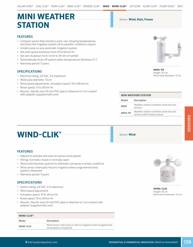
139
SEN
SOR
S
Visit hunterindustries.com RESIDENTIAL & COMMERCIAL IRRIGATION | Built on Innovation®
WIND-CLIK® Sensor: Wind
FEATURES• Compact sensor that monitors wind, rain, freezing temperatures,
and shuts the irrigation system off as weather conditions require• Installs easily on any automatic irrigation system• Set wind speed shutdown from 19 to 56 km/hr• Set rain shutdown from 3 mm to 19 mm of rainfall• Automatically shuts off system when temperatures fall below 3° C• Warranty period: 5 years
SPECIFICATIONS• Electrical rating: 24 VAC, 5 A maximum• Wind vane diameter: 13 cm• Wind speed adjustments: Actuation speed: 19 to 56 km/hr• Reset speed: 13 to 39 km/hr• Mounts: Slip fits over 55 mm PVC pipe or attaches to 1 cm conduit
with adapter (supplied with unit)
Sensor: Wind, Rain, FreezeMINI WEATHER STATION
FEATURES• Adjusts to activate and reset at various wind speeds• Wiring: normally-closed or normally-open• Works with fountain systems to eliminate overspray in windy conditions• Wind sensor interrupts/returns irrigation when programmed wind
speed is measured• Warranty period: 5 years
SPECIFICATIONS• Switch rating: 24 VAC, 5 A maximum• Wind speed adjustment• Actuation speed: 19 to 56 km/hr• Reset speed: 13 to 39 km/hr• Mounts: Slip fits over 50 mm PVC pipe or attaches to 1 cm conduit with
adapter (supplied with unit)
MWS-FRHeight: 20 cm Wind Vane Diameter: 13 cm
WIND-CLIKHeight: 10 cm Wind Vane Diameter: 13 cm
MINI WEATHER STATION
Model Description
MWSWeather station combines wind and rain sensors
MWS-FRWeather station combines wind and rain sensors with a freeze sensor
WIND-CLIK®
Model Description
WIND-CLIKWind sensor interrupts or returns irrigation when programmed wind speed is measured.
SOLAR SYNC® SOIL-CLIK® RAIN-CLIK® MINI-CLIK® FREEZE-CLIK® MWS WIND-CLIK® HC FLOW FLOW-CLIK® FLOW-SYNC® WFS
Table of Contents:Mini Weather Station
Wind-Clik®
Cross References:
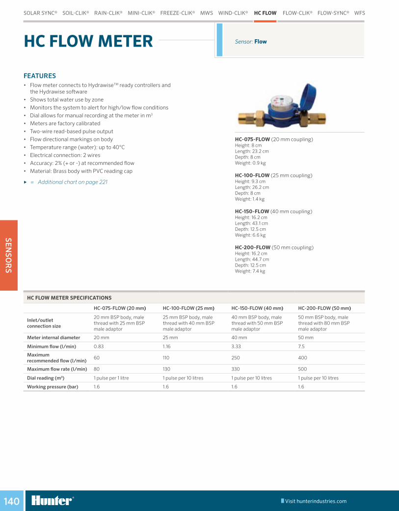
140
SENSO
RS
Visit hunterindustries.com
SOLAR SYNC® SOIL-CLIK® RAIN-CLIK® MINI-CLIK® FREEZE-CLIK® MWS WIND-CLIK® HC FLOW FLOW-CLIK® FLOW-SYNC® WFS
HC-075-FLOW (20 mm coupling)Height: 8 cmLength: 23.2 cmDepth: 8 cmWeight: 0.9 kg
HC-100-FLOW (25 mm coupling)Height: 9.3 cmLength: 26.2 cmDepth: 8 cmWeight: 1.4 kg
HC-150-FLOW (40 mm coupling)Height: 16.2 cmLength: 43.1 cmDepth: 12.5 cmWeight: 6.6 kg
HC-200-FLOW (50 mm coupling)Height: 16.2 cmLength: 44.7 cmDepth: 12.5 cmWeight: 7.4 kg
Sensor: FlowHC FLOW METER
HC FLOW METER SPECIFICATIONS
HC-075-FLOW (20 mm) HC-100-FLOW (25 mm) HC-150-FLOW (40 mm) HC-200-FLOW (50 mm)
Inlet/outlet connection size
20 mm BSP body, male thread with 25 mm BSP male adaptor
25 mm BSP body, male thread with 40 mm BSP male adaptor
40 mm BSP body, male thread with 50 mm BSP male adaptor
50 mm BSP body, male thread with 80 mm BSP male adaptor
Meter internal diameter 20 mm 25 mm 40 mm 50 mm
Minimum flow (l/min) 0.83 1.16 3.33 7.5
Maximum recommended flow (l/min)
60 110 250 400
Maximum flow rate (l/min) 80 130 330 500
Dial reading (m3) 1 pulse per 1 litre 1 pulse per 10 litres 1 pulse per 10 litres 1 pulse per 10 litres
Working pressure (bar) 1.6 1.6 1.6 1.6
Table of Contents:HC Flow Meter
Cross References:
FEATURES• Flow meter connects to HydrawiseTM ready controllers and
the Hydrawise software• Shows total water use by zone• Monitors the system to alert for high/low flow conditions• Dial allows for manual recording at the meter in m3
• Meters are factory calibrated• Two-wire read-based pulse output• Flow directional markings on body• Temperature range (water): up to 40°C• Electrical connection: 2 wires• Accuracy: 2% (+ or -) at recommended flow• Material: Brass body with PVC reading cap
► = Additional chart on page 221

141
SEN
SOR
S
Visit hunterindustries.com RESIDENTIAL & COMMERCIAL IRRIGATION | Built on Innovation®
FEATURES• Automatically shuts down system if an overflow condition occurs• Helps protect from flooding damage and erosion• Calibration for precise system control: Single button allows each system to be
programmed at a specified flow level• Works with most Hunter and most non-Hunter controllers• Multi-colour LED provides system status to display when power is applied and
indicates if flow is within limits• Compatible with most commercial and residential piping systems: Large flow
range provides complete flexibility• One button system calibration to set highest flow zone• Warranty period: 5 years
SPECIFICATIONS• Flow-Clik Interface Panel: 90 cm leads provided for easy wiring to controller
(2 wires to controller, 24 VAC terminals and 2 wires to sensor and terminals)• Current draw: 24 VAC, 0.025 A• Switching current: 2 A maximum• Max. distance between interface panel and sensor: 300 m• Sensor Wiring: 2 x direct burial, 0.82 mm2 or greater, colour-coded or marked
for polarity, up to 300 m from controller• Programmable start up delay: 0 to 300 seconds• Programmable interrupt period: 2 to 60 minutes
Sensor: FlowFLOW-CLIK®
Flow-Clik sensor and module shown with receptacle tees
FLOW-CLIK®
Model Description
FLOW-CLIK*Standard kit for all 24 VAC controllers. Includes sensor and interface module, sensor requires FCT for pipe installation.
REQUIRED USER INSTALLED OPTION (SPECIFY SEPARATELY)
Model Description
FCT-100 1" (25 mm) Schedule 40 sensor receptacle tee
FCT-150 1½" (40 mm) Schedule 40 sensor receptacle tee
FCT-158 1½" (40 mm) Schedule 80 sensor receptacle tee
FCT-200 2" (50 mm) Schedule 40 sensor receptacle tee
FCT-208 2" (50 mm) Schedule 80 sensor receptacle tee
FCT-300 3" (80 mm) Schedule 40 sensor receptacle tee
FCT-308 3" (80 mm) Schedule 80 sensor receptacle tee
FCT-400 4" (100 mm) Schedule 40 sensor receptacle tee
Notes:* FCT for pipe installation sold separately
BSP ADAPTERS FOR FCT FITTINGS
Diameter Model
1" (25 mm) 795700
1½" (40 mm) 795800
2" (50 mm) 2414003" (80 mm) 477800
FLOW RANGE
Pipe Diameter
Operating RangeMinimum Suggested Maximum*
l/min m3/hr l/min m3/hr1" (25 mm) 7.6 0.45 64 3.84
1½" (40 mm) 19 1.14 132 8.0
2" (50 mm) 37.8 2.26 208 12.5
3" (80 mm) 106 6.36 450 27.04" (100 mm) 129 7.74 750 45.0
Notes: * Good design practice dictates the maximum flow not to exceed 1.5 m/sec. Suggested maximum flow is based upon Class 200 IPS plastic pipe.
SOLAR SYNC® SOIL-CLIK® RAIN-CLIK® MINI-CLIK® FREEZE-CLIK® MWS WIND-CLIK® HC FLOW FLOW-CLIK® FLOW-SYNC® WFS
Table of Contents:Flow-Clik®
Cross References:

142
SENSO
RS
Visit hunterindustries.com
FEATURES• Simple two-wire connection to ACC and I-Core® controllers
(up to 300 m)• Feeds flow data (gallons or liters) to controller, for flow recording
and monitoring purposes• Robust waterproof construction • Provides station level flow monitoring for reaction to high
or low flow conditions• Helps prevent damage and waste from leaks and breaks in
piping system
SPECIFICATIONS• Recommended pressure range: 1.5 to 15.0 bar; 150 to 1500 kPa• Pressure Loss: < 0.009 bar; 0.9 kPa• Wiring: 2 x direct burial, 0.82 mm2 or greater, colour-coded or marked for
polarity, up to 300 m from controller.
Sensor: FlowFLOW-SYNC®
Impeller-type flow meter, requires FCT for pipe installation (sold separately)
FLOW-SYNC
Model Description
HFS*Hunter Flow-Sync sensor, use with ACC and I-Core controllers, sensor requires FCT for pipe installation
REQUIRED USER INSTALLED OPTION (SPECIFY SEPARATELY)
Model Description
FCT-100 1" (25 mm) Schedule 40 sensor receptacle tee
FCT-150 1½" (40 mm) Schedule 40 sensor receptacle tee
FCT-158 1½" (40 mm) Schedule 80 sensor receptacle tee
FCT-200 2" (50 mm) Schedule 40 sensor receptacle tee
FCT-208 2" (50 mm) Schedule 80 sensor receptacle tee
FCT-300 3" (80 mm) Schedule 40 sensor receptacle tee
FCT-308 3" (80 mm) Schedule 80 sensor receptacle tee
FCT-400 4" (100 mm) Schedule 40 sensor receptacle tee
Note:* Flow-Sync (sensor only) for use with ACC and I-Core controllers. Requires FCT for pipe installation (sold separately).
BSP ADAPTERS FOR FCT FITTINGS
Diameter Model
1" (25 mm) 795700
1½" (40 mm) 795800
2" (50 mm) 2414003" (80 mm) 477800
FLOW RANGE
Pipe Diameter
Operating RangeMinimum Suggested Maximum*
l/min m3/hr l/min m3/hr1" (25 mm) 7.6 0.45 64 3.84
1½" (40 mm) 19 1.14 132 8.0
2" (50 mm) 37.8 2.26 208 12.5
3" (80 mm) 106 6.36 450 27.04" (100 mm) 129 7.74 750 45.0
Notes: * Good design practice dictates the maximum flow not to exceed 1.5 m/sec. Suggested maximum flow is based upon Class 200 IPS plastic pipe.
SOLAR SYNC® SOIL-CLIK® RAIN-CLIK® MINI-CLIK® FREEZE-CLIK® MWS WIND-CLIK® HC FLOW FLOW-CLIK® FLOW-SYNC® WFS
Table of Contents:Flow-Sync®
Cross References:

143
SEN
SOR
S
Visit hunterindustries.com RESIDENTIAL & COMMERCIAL IRRIGATION | Built on Innovation®
Sensor: FlowWFS
FEATURES• Feeds flow data (gallons or liters) to controller, for flow recording and
monitoring purposes• Robust waterproof construction• Provides station-level flow monitoring for reaction to high- or
low-flow conditions• Helps prevent damage and waste from leaks and breaks in piping system
SPECIFICATIONS• Maximum distance sensor to module: 152 m• Recommended pressure range: 0 to 15.0 bar; 0 to 1500 kPa• Pressure loss: < 0.07 bar; 0.7 kPa
APPROVALS• FCC and CE approved
WIRELESS FLOW SENSOR
Model Description
WFS-INT Wirelss Flow Sensor Kit - International 868 mHz
WFS-T-INT Wireless Flow Sensor Kit Transmitter Only - International 868 mHz
WFS-R-INT Wireless Flow Sensor Kit Receiver Only - International 868 mHz
WFS-SEN Wireless Flow Sensor Kit Sensor Only
WFS-LITHBATT Wireless Flow Sensor Lithium Battery
WFS-ALKBATT Wireless Flow Sensor Alkaline Battery with Cage
REQUIRED USER INSTALLED OPTION (SPECIFY SEPARATELY)
Model Description
FCT-100 1" (25 mm) Schedule 40 sensor (white) receptacle tee
FCT-150 1½" (40 mm) Schedule 40 sensor (white) receptacle tee
FCT-158 1½" (40 mm) Schedule 80 sensor (grey) receptacle tee
FCT-200 2" (50 mm) Schedule 40 sensor (white) receptacle tee
FCT-208 2" (50 mm) Schedule 80 sensor (grey) receptacle tee
FCT-300 3" (80 mm) Schedule 40 sensor (white) receptacle tee
FCT-308 3" (80 mm) Schedule 80 sensor (grey) receptacle tee
FCT-400 4" (100 mm) Schedule 40 sensor (white) receptacle tee
FLOW RANGE
Wireless Flow Sensor Diameter
Operating RangeMinimum Suggested Max*
l/min m3/hr l/min m3/hr1" (25 mm) 7.6 0.45 64 3.84
1½" (40 mm) 19 1.14 132 8.0
2" (50 mm) 37.8 2.26 208 12.5
3" (80 mm) 106 6.36 450 27.04" (100 mm) 129 7.74 750 45.0
Notes: * Good design practice dictates the maximum flow not to exceed 1.5 m/sec. Suggested maximum flow is based upon Class 200 IPS plastic pipe.
SOLAR SYNC® SOIL-CLIK® RAIN-CLIK® MINI-CLIK® FREEZE-CLIK® MWS WIND-CLIK® HC FLOW FLOW-CLIK® FLOW-SYNC® WFS
WFS
WIRELESS FLOW SENSOR
Table of Contents:WFS (Wireless Flow Sensor)
Cross References:

MIC
RO
144
Table of Contents:Micro
Cross References:

MIC
RO
145
MICROSECTION 08:

MIC
RO
146
ADVANCED FEATURES
Table of Contents:
Cross References:Micro - Advanced Features
Engineered for peak performance in even the harshest conditions, Hunter’s ultra-durable micro irrigation products are the toughest and most resilient in the industry. Combining unmatched strength with high-quality, long-lasting performance in the field, our products ensure precise water delivery for years to come.
RIGID RISERS
Designed for rugged system designs. Accept 10-32 threaded components. A perfect solution for annual flower beds and planters.
PLD-LOC FITTINGS
PLD-Loc Fittings are easier and faster than other fittings with easy push-on installation. Threads lock them into place. Fits all dripline inside diameters: 16 mm, 17 mm, 18 mm, and ½" black poly tubing. Reusable - perfect for drip irrigation maintenance.
MULTI-PURPOSE BOX
The HDPE Box is just the right size to provide easy access to air relief, automatic flush valves, ball valves, large emitters, wiring connections, and even valves or filters.
ECO-INDICATOR
The Eco-Indicator provides a visual signal that the system is operating. Pair with Eco-Mat and Eco-Wrap subsurface systems or any drip system where emitters are obscured.
ECO-MAT®
Designed to suit a variety of hard-to-irrigate areas, the Eco-Mat uses an engineered combination of Hunter's fleece-wrapped professional landscape dripline attached to a specialized fleece blanket, which evenly disperses water within the root zone.
ECO-WRAP®
Eco-Wrap is Hunter’s fleece-wrapped professional landscape dripline, which transports water quickly and more efficiently than bare dripline.
POINT SOURCE EMITTERS
A wide range of flow rates offers you the flexibility to give individual plants and trees the right amount of water from a single emitter. Color-coded for flow identification with coined edges for easy gripping during installation.
PLD - PROFESSIONAL LANDSCAPE DRIPLINE
Hunter's PLD provides a pressure compensation system with built-in check valve to help prevent emitter clogging and water loss and ensure even flows on all terrains and lateral lengths.
RZWS - ROOT ZONE WATERING SYSTEM
The Root Zone Watering System features Hunter’s patented StrataRootTM
design, which is a series of internal baffles that deliver water to all levels of the root zone. The RZWS is pre-assembled to save time, and the enclosed design and grate protect irrigation hardware from vandalism.
DRIP CONTROL ZONE KITS
Hunter offers the absolute highest quality in control zone kits, from low-flow to high-flow systems. Some features, such as our Filter SentryTM scrubber, add further value to an already superior kit.
IH RISERS
Heavy-duty commercial-grade risers with a vandal-resistant design. Available in 30 cm or 61 cm blank or emitter style. Emitter style includes screens with check valves. Brown components blend in with the landscape.
MULTI-PORT EMITTERS
Pressure-compensating commercial-grade emitters for all PVC systems. Perfect for mixed plantings or a series of shrubs. Color coded to match other Hunter emitters.
AIR/VACUUM RELIEF VALVE
The Hunter AVR is designed to reliably discharge air during system start-up and allow air into the line during shutdown. Assisting in reducing water hammer, the valve should close reliably even with low water pressure.
AUTOMATIC FLUSH VALVE
Automatically flushes debris at system start-up.

MIC
RO
147
APPLICATION COMPARISON
QUICK SPECS ECO-MAT® ECO-WRAP® PLD MLD IH RISER PSE MULTI- PORT
MICRO SPRAYS RZWS
EMITTER SPACING 30 cm 30 cm 30, 45, 60 cm 30, 45 cm - - - - -
FLOW RATES 2.2 l/hr 2.2 l/hr 1.4–3.8 l/hr 1.5–3.2 l/hr 1.9–22.7 l/hr2, 4, 8, 15,
23 l/hr2, 4, 8, 15 l/hr 0-119 l/hr 0.9–1.9 l/min
NON-DRAINING (CHECK VALVE) ⬤ ⬤ ⬤ ⬤ ⬤
WARRANTY 5 Years 5 Years 5 Years 1 Year 2 Years 2 Years 2 Years 1 Year 2 Years
ADVANCED FEATURES
FLEECE TECHNOLOGY ⬤ ⬤
PRESSURE COMPENSATION
⬤ ⬤ ⬤ ⬤ ⬤ ⬤ ⬤
STRATA ROOT SYSTEM ⬤
ADJUSTABLE RADIUS ⬤
PLANT TYPE
TEMPORARY IRRIGATION ⬤ ⬤ ⬤
GROUNDCOVER, SHRUBS, TREES AT GRADE (LESS THAN 15 CM DEEP)
⬤ ⬤ ⬤ ⬤ ⬤
TURF ⬤ ⬤
SMALL SHRUBS, PLANTS AND GROUNDCOVER
⬤ ⬤ ⬤ ⬤ ⬤ ⬤ ⬤
TREES AND LARGE SHRUBS
⬤ ⬤ ⬤ ⬤ ⬤ ⬤
SPREADING SUCCULENTS, MOSS, AND MAT PLANTS ⬤ ⬤ ⬤
APPLICATIONUSE WITH RECLAIMED WATER
⬤ ⬤ ⬤ ⬤ ⬤ ⬤ ⬤
SUBSURFACE INSTALLATION
⬤ ⬤ ⬤ ⬤ ⬤
POTTED PLANTS ⬤ ⬤ ⬤ ⬤ ⬤
HEDGE ROWS ⬤ ⬤ ⬤
DENSE MIXED PLANTINGS ⬤ ⬤ ⬤ ⬤ ⬤
RESIDENTIAL GARDENING ⬤ ⬤ ⬤ ⬤ ⬤ ⬤ ⬤
ROADWAY MEDIANS ⬤ ⬤ ⬤ ⬤ ⬤ ⬤ ⬤
GREEN ROOF ⬤ ⬤
TREES ⬤ ⬤ ⬤ ⬤ ⬤ ⬤ ⬤
From Professional Landscape Dripline to our root zone watering system, Hunter's micro irrigation solutions are designed to apply water efficiently and precisely where it's needed. Choose the combination of products best suited for your application and plant type using the chart below.

Visit hunterindustries.com148
MIC
RO
Subsurface Irrigation: Under Turf, Green Roofs, Gardens, Small ShrubsECO-MAT®
UNMATCHED UNIFORMITY AND WATER SAVINGS
ECO-MAT TECHNICAL SPECIFICATIONS
16 MM 17 MM
Flow 2.2 l/hr; 0.13 m3/hr
2.2 l/hr; 0.13 m3/hr
Roll Length 100 m 90 m
Width 0.80 m 0.80 m
m2 80 60
Operating Pressure 1.0 to 3.5 bar; 100 to 350 kPa
1.0 to 3.5 bar; 100 to 350 kPa
Minimum Filtration 120 mesh; 125 microns
120 mesh; 125 microns
Emitter Spacing 30 cm 30 cm
Lateral Row Spacing 35 cm 35 cm
FEATURES• Water-saving with nearly 100% distribution uniformity• Promotes healthier plant roots• Eliminates overspray onto sidewalks, buildings, or vehicles• Perfect for irrigating difficult areas• The fleece wrap protects against root intrusion without using
toxic chemicals or metal byproducts• Water holding capacity of 1.89 l/m2
• Pressure compensating• Check valves kp the line charged up to 1.5 m and prevent
low-point drainage• Recommended for use with all Hunter Drip Control Zone Kits• For maximum water savings, use with Hunter Soil-Clik®• Warranty period: 5 years (2 additional years for environmental
stress cracking)
OPERATING SPECIFICATIONS• Minimum flitration 120 mesh; 125 microns• Operating pressure range: 1.0 to 3.5 bar; 100 to 350 kPa• Compatible with 16 mm and 17 mm insert barb fittings• Recommended installation depth range: 10 cm to 30 cm
For maximum run length distances for the Eco-Mat or Eco-Wrap®, reference the Maximum Run Length Chart on page 220. Use 2.2 l/hr for flow and 30 cm emitter spacing.
SUBSURFACE PLD MLD ECO-ID TUBING FITTINGS MB AVR AFV IH RISERS PSE MPE RISERS DRIP ZONE MICRO SPRAYS RZWS
10-15 cm
Concrete Turf
Eco-Mat should overlap by approximately 15 cm during installation to establish 35 cm lateral spacing.
Roll fleece material as shown to insure 10 cm maximum lateral distance from hardscape.
Example: Notes: * For purchasing, always round up to the nearest whole roll of Eco-Mat.
SIZE ROLL APPROXIMATE COVERAGE WITH 15 CM OVERLAP
31 m 22 m2
90 m 66 m2
Size roll = Irrigated landscape area
area of roll coverage
2.5 (90 m)
= 167 m2
66 m2
Eco-Mat Installed
Table of Contents:Eco-Mat®
Cross References:

Visit hunterindustries.com 149
MIC
RO
RESIDENTIAL & COMMERCIAL IRRIGATION | Built on Innovation®
Subsurface Irrigation: Under Turf, Gardens, Shrubs, Trees
FEATURES• High distribution uniformity surpassed only by the Eco-Mat• Promotes healthier plant roots• Eliminates overspray onto sidewalks, buildings, or vehicles• Ideal for difficult areas between flagstone and pavers• Use with PLD-Loc or barbed PLD fittings• Fleece-wrapped professional landscape dripline• Transports water faster and more efficiently than bare dripline• Pressure compensating• Check valves keep the line charged up to 1.5 m and prevent
low point drainage• Fleece fully moistens in less than 3 minutes allowing far better
uniformity than bare dripline• Recommended for use with all Hunter Drip Control Zone Kits• Warranty period: 5 years (2 additional years for environmental
stress cracking)
OPERATING SPECIFICATIONS• Minimum filtration 120 mesh; 125 microns• Operating pressure range: 1.0 to 3.5 bar; 100 to 350 kPa• Compatible with 16 mm and 17 mm insert barb fittings
ECO-WRAP®
ECO-WRAP TECHNICAL SPECIFICATIONS
16 MM 17 MM
Flow 2.2 l/hr; 0.13 m3/hr
2.2 l/hr; 0.13 m3/hr
Roll Length 100 m 76 m
Operating Pressure 1.0 to 3.5 bar; 100 to 350 kPa
1.0 to 3.5 bar; 100 to 350 kPa
Minimum Filtration 120 mesh; 125 microns
120 mesh; 125 microns
Emitter Spacing 30 cm 30 cm
Eco-Wrap
SUBSURFACE PLD MLD ECO-ID TUBING FITTINGS MB AVR AFV IH RISERS PSE MPE RISERS DRIP ZONE MICRO SPRAYS RZWS
Table of Contents:Eco-Wrap®
Cross References:Eco-Wrap®
Micro Solutions Eco Wrap

Visit hunterindustries.com150
MIC
RO
FEATURES• Pressure compensating emitters• Flow rates of 1.4, 2.2, 3.8 l/hr• Emitter spacing at 30 cm, 45 cm, and 60 cm• Available without emitters (blank)• Use with PLD-Loc or barbed PLD fittings• Strong UV resistance• Warranty period: 5 years (2 additional years for environmental
stress cracking) • Check valves keep the line charged up to 1.5 m and prevent low-
point drainage (PLD-CV only)• Anti-siphon prevents debris from entering emitters when
used subsurface (PLD-CV only)
OPERATING SPECIFICATIONS• PLD-CV:
- Pressure compensating, non-draining emitters - Operating pressure range: 1.0 to 3.5 bar; 100 to 350 kPa - Minimum filtration: 120 mesh; 125 microns
• PLD-PC and PLD-R: - Pressure compensating - Operating pressure range: 10 to 50 PSI - Minimum filtration: 120 mesh; 125 microns
► = Application Rate charts on page 220
Flow: 1.4, 2.2, 3.8 l/hrSurface Irrigation: Shrub Rows, Gardens, Tree Rings
PLDPROFESSIONAL LANDSCAPE DRIPLINE PLD-CV, PLD-PC, PLD-R
PLD 16 MM – SPECIFICATION BUILDER: ORDER 1 + 2 + 3
1 Model 2 Spacing 3 Length
PLD-22 = 2.2 l/hr Flow 30 cm 100 m
PLD-38 = 3.8 l/hr Flow 50 cm 200 m
400 m
Examples: PLD-22-30-100-CV = 2.2 l/hr dripline with 30 cm spacing in a 100 m roll PLD-22-50-200-CV = 2.2 l/hr dripline with 50 cm spacing in a 200 m roll PLD-38-50-400-CV = 3.8 l/hr dripline with 50 cm spacing in a 400 m roll
PLD 17 MM – SPECIFICATION BUILDER: ORDER 1 + 2 + 3 + 4
1 Model 2 Spacing 3 Length 4 Options
PLD-04 = 1.4 l/hr Flow 12 = 30 cm 100 = 30 m* CV
PLD-06 = 2.2 l/hr Flow 18 = 45 cm 250 = 75 m PCPLD-10 = 3.8 l/hr Flow 24 = 60 cm 500 = 150 m
R = Reclaimed (available in 2.3 and 3.8 l/hr models only)PLD-BLNK = No Emitters 1K = 300 m
Example: PLD-04-12-250-CV = 1.4 l/hr check valve dripline with 30 cm spacing in a 75 m roll * 30 m rolls available only in models PLD-CV-100, PLD-06-12-100, PLD-10-12-100, and PLD-10-18-100
PLD-CV
PLD-PC
PLD-R (Reclaimed)
Optional colour for reclaimed water sources, available for 17 mm only.
PLD Installed
SUBSURFACE PLD MLD ECO-ID TUBING FITTINGS MB AVR AFV IH RISERS PSE MPE RISERS DRIP ZONE MICRO SPRAYS RZWS
Table of Contents:PLD
Cross References:Micro Solutions PLD

MIC
RO
Visit hunterindustries.com RESIDENTIAL & COMMERCIAL IRRIGATION | Built on Innovation® 151
MLDFlow: 1.5-3.2 l/hrSurface Irrigation: Short Runs and PlantersFittings: All ¼" barb fittings
FEATURES• Perfect for short runs and planters• 30.5 m and 76.2 m rolls• 15 cm or 30 cm emitter spacing• 76 m rolls uncoil from the inside of the roll for easy,
no-hassle dispensing• Offered in both brown or black• Use with standard 6 mm barb fittings• Warranty period: 2 years
OPERATING SPECIFICATIONS• 6.4 mm outside diameter x 4.5 mm inside diameter• Operating pressure: 0.7 to 2.8 bar; 70 to 280 kPa• Materials: LLDPE• Minimum bending radius: 30 cm• Minimum filtration: 150 mesh; 100 microns
► = Flow chart available on page 220
MINI LANDSCAPE DRIPLINE
FEATURES• Visible yellow stem indicates system is in operation• Attach to polyethylene or PVC via 1/ 2" MPT connection• Requires 0.85 bar to pop-up• Commercial-grade body and stem• Warranty: 2 years
OPERATING SPECIFICATIONS• Operating pressure range: 0 to 4.2 bar• Indication of system operation: 0.85 to 4.2 bar
ECO-INDICATOR Uses: Drip System Indicator
ECO-ID
Pair with Eco-Mat® and Eco-Wrap® subsurface systems.
MLD Installed
MLD
Example: MLD-05 - 12 - 250 = 1.9 l/hr mini dripline with 30 cm spacing in a 76 m roll, brown
MLD – SPECIFICATION BUILDER: ORDER 1 + 2 + 3 + 4
1 Model 2 Spacing 3 Length 4 Options
MLD-05 06 = 15 cm 100 = 30 m BL = Black
12 = 30 cm 250 = 76 m (blank) = Brown
SUBSURFACE PLD MLD ECO-ID TUBING FITTINGS MB AVR AFV IH RISERS PSE MPE RISERS DRIP ZONE MICRO SPRAYS RZWS
MAXIMUM RUN LENGTH
Pressure (bar/kPa)
Emitter Spacing (cm) Run Length (m)
1.7/170 15 4.6
1.7/170 30 9.2
2.8/280 15 4.62.8/280 30 9.2
Notes: Run lengths based on maintaining consistent flows.
Table of Contents:MLD
Eco-Indicator
Cross References:

MIC
RO
Visit hunterindustries.com152
Uses: Water transportationSize: OD 17.8 mm x ID 15.2 mm
Uses: Water transportationSize: OD 6.4 mm x ID 4.3 mm
FEATURES• 17.8 mm outside diameter x 15.2 mm inside diameter• Connect using PLD-Loc fittings• Made with linear low density UV-resistant polyethylene• Thicker wall, commercial grade• Warranty period: 2 years
OPERATING PRESSURE• 0 to 4.1 bar; 0 to 410 kPa
FEATURES• 6.4 mm outside diameter x 4.3 mm inside diameter• Connect using standard 6 mm fittings• Offered in vinyl or polyethylene• UV Resistant materials• Polyethylene is better choice in warm climates• Vinyl is more flexible and useful in cold climates• Warranty: 2 years
OPERATING PRESSURE• 0 to 4.1 bar; 0 to 410 kPa
SUPPLY TUBING17 MM POLYETHYLENE PROFESSIONAL TUBING
6 MM POLYETHYLENE AND VINYL TUBING
DISTRIBUTION TUBING
17 mm PE Tubing
6 mm Tubing
17 MM PE TUBING – SPECIFICATION BUILDER: ORDER 1 + 2 + 3
1 Model 2 Tubing Diameter 3 Length
TWPE = Thick-Walled Polyethylene Tubing
700 = 17.8 mm outside diameter
100 = 30 m
250 = 76 m
500 = 152 m
1K = 305 m
Example: TWPE-700 - 250 = 17 mm polyethylene tubing in a 76 m roll
6 MM TUBING – SPECIFICATION BUILDER: ORDER 1 + 2 + 3
1 Model 2 Tubing Diameter 3 Length
HQPE = Polyethylene Tubing 250 = 6.4 mm outside diameter
100 = 30 m
HQV = Vinyl Tubing 250 = 76 m
1K = 305 m
Example: HQPE-250 - 1K = 6 mm polyethylene tubing in a 305 m roll
Table of Contents:Supply TubingDistribution Tubing
Cross References:
SUBSURFACE PLD MLD ECO-ID TUBING FITTINGS MB AVR AFV IH RISERS PSE MPE RISERS DRIP ZONE MICRO SPRAYS RZWS

MIC
RO
Visit hunterindustries.com RESIDENTIAL & COMMERCIAL IRRIGATION | Built on Innovation® 153
Fittings: 16-18 mm DriplineUses: Premium Fittings
BARBED FITTINGS• Acetal material• Dual barb provides stronger hold than single barb• Ideal for use with Eco-Mat®, Eco-Wrap®, PLD• Fits 17 mm dripline and tubing• Brown colour to match PLD dripline• No clamps necessary• Warranty period: 1 year
OPERATING SPECIFICATIONS• Maximum pressure: 4.1 bar; 410 kPa
PLD-LOC• High-quality glass-filled polypropylene • Easy push-on installation, threads lock it into place• Easier and faster than other fittings• Fits multiple sizes of dripline and tubing (inside
diameter range from 13.3 mm to 15.8 mm)• Brown colour blends in with dripline and landscape• Reusable and ideal for drip irrigation maintenance• Warranty period: 2 years
OPERATING SPECIFICATIONS• Maximum pressure: 4.1 bar; 410 kPa
PLD FITTINGS
PLD LOC FITTINGS
PLD-LOC 050½" Male Pipe Thread x Loc
PLD-LOC 075¾" Male Pipe Thread x Loc
PLD-LOC CPLLocking Coupler
PLD-LOC TEELocking Tee
PLD-LOC ELBLocking Elbow
PLD-LOC CAPEnd Cap x Loc
PLD-LOC FHS¾" Female Hose Swivel x Loc
FITTINGS
PLD-050½" MPT x 17 mm Barb
PLD-075¾" MPT x 17 mm Barb
PLD-TEE17 mm Barb Tee
PLD-BV17 mm Barb Shut-off Valve
PLD-ELB17 mm Barb Elbow
PLD-CAP17 mm Barb x ½" MPT with Cap
PLD-075-TBTEE17 mm Barb Tee x ¾" Thread
FITTINGS
PLD-CPL 17 mm Barb Coupling
Fittings: 17 mm DriplineUses: Barbed Fittings
PLD-CRS 17mm Barb Cross
PLD-IAEInsert Adapter x 17 mm Elbow
PLD-IACInsert Adapter x 17 mm Coupling
PLD-050-TB-TEE1/ 2" FPT x 17 mm Barb Tee
PLD-075-TB-ELB ¾" FPT x 17 mm Barb Elbow
SUBSURFACE PLD MLD ECO-ID TUBING FITTINGS MB AVR AFV IH RISERS PSE MPE RISERS DRIP ZONE MICRO SPRAYS RZWS
Table of Contents:Fittings
Cross References:

MIC
RO
Visit hunterindustries.com154
Uses: For Protection and Easy Access of Irrigation Components
FEATURES• Small rectangular box• Durable HDPE• Black base with choice of lid color: tan, green, purple• Overlapping lid prevents debris from entering box• Knock-out bolt hole• Reinforced base and lid for strength• UV-protected nonslip lid• Warranty period: 2 year
MULTI-PURPOSE BOX
SUBSURFACE PLD MLD ECO-ID TUBING FITTINGS MB AVR AFV IH RISERS PSE MPE RISERS DRIP ZONE MICRO SPRAYS RZWS
MULTI-PURPOSE BOX
Model Description
MB-0811-G Multi-purpose box with green lid
MB-0811-T Multi-purpose box with tan lid
MB-0811-R Multi-purpose box with purple lid
6 mm Barb Fittings
4.6 mm barb use with MLD or any vinyl or PE 6 mm tubing, UV-stabilised materials, and durable single barb connection.
Fittings: 16-18 mm DriplineUses: Barbed and Premium FittingsBARBED FITTINGS
6 MM BARBED FITTINGS• Acetal material (superior hold)• Fit 6 mm tubing sizes with ID of 4.0 mm to 4.4 mm• Use with Mini Landscape Dripline (MLD)• Goof plug lays flat and holds securely without leaking• Warranty period: 1 year
OPERATING SPECIFICATIONS• Maximum pressure: 6.9 bar• Material: UV-stabilised acetal
Table of Contents:MB
Cross References:
QB-TEE6 mm Barb Tee
QB-ELB6 mm Barb Elbow
QB-CPL6 mm Barb Coupling
QB-CRS6 mm Barb Cross
GP-025Goof Plug

MIC
RO
Visit hunterindustries.com RESIDENTIAL & COMMERCIAL IRRIGATION | Built on Innovation® 155
Uses: Air Release and Vacuum Relief
FEATURES• Releases air pockets without premature closure• Leak-free closure after release
• Help prevent system collapse through vacuum relief
• Corrosion resistant
• UV protected
• Lightweight and durable
• Warranty period: 2 years
OPERATING SPECIFICATIONS• Operating pressure range: up to 5.5 bar
Uses: Automatically Flushes Debris at System Start up
FEATURES• 1/ 2" MPT or 17 mm barb models
• Removable top for diaphragm maintenance
• Reversible diaphragm for high or low flow
• Warranty period: 1 year
OPERATING SPECIFICATIONS• Max operating pressure: 4.1 bar• Low-flow diaphragm side: 7.6 to 18.9 l/m• High-flow diaphragm side: 18.9 to 45.4 l/m
AFV-BAutomatic flush valve with 17 mm barb connection
AFV-TAutomatic flush valve with 1/ 2" MPT connection
AUTOMATIC FLUSH VALVE
SUBSURFACE PLD MLD ECO-ID TUBING FITTINGS MB AVR AFV IH RISERS PSE MPE RISERS DRIP ZONE MICRO SPRAYS RZWS
AVR-075Height: 13 cmWidth: 5 cmInlet: ¾” MPT
PLD-AVR½" Air/Vacuum Relief Valve
AIR/VACUUM RELIEF VALVE
Table of Contents:Air/Vacuum Relief Valve
Automatic Flush Valve
Cross References:

Visit hunterindustries.com156
MIC
RO
IH RISERS
FEATURES• Heavy-duty, military-grade, vandal-resistant design• Made of flexible PVC for durability• Brown components blend in with landscape• Accepts any ½" FPT emitter• Ideal for slopes• Pre-assembly reduces labour by up to 50%• On grade or below grade installation• Available in multiple lengths for easy assembly• Pre-assembled with ½" MPT adapter and specified emitter with check valve• Available as components for custom assemblies• Check valve holds back 3.6 m of head• Warranty period: 2 years
OPERATING SPECIFICATIONS• Maximum flow: 26.5 l/min• Maximum pressure: 4.1 bar; 410 kPa
Flow: 2, 4, 8, 15, 23 l/hrSurface Irrigation: Robust Point Source Irrigation
IH RISER FLEXIBLE PVC
Model Description
IH-RISER-06 15 cm flexible PVC riser
IH-RISER-12 30 cm flexible PVC riser
IH-RISER-18 45 cm flexible PVC riser
IH-RISER-24 61 cm flexible PVC riser
IH-RISER-36 91 cm flexible PVC riser
IH-RISER-12-R 30 cm flexible PVC riser (reclaimed)
IH-RISER-24-R 61 cm flexible PVC riser (reclaimed)
IH-RISER-36-R 91 cm flexible PVC riser (reclaimed)
SCREEN-CV Filter screen with 2.7 m check valve
IH-FIT-3850 ⅜" x ½" MPT IH fitting
IH-FIT-3850-R ⅜" x ½" MPT IH fitting (reclaimed)
IH-250 76 m length of irrigation hose
IPS-050-250 76 m length of ½" IPS
IH RISERS
SCREEN-CVFilter screen with 2.7 m check valve
IH-FIT-3850-R3/ 8" x ½" MPT IH fitting (reclaimed)
IH-FIT-38503/ 8" x ½" MPT IH fitting
Flexible PVC for creating headers or custom risers
IH-250IPS-050-250
Example: IH-12-10-CV = 30 cm irrigation hose riser with 4 l/hr emitter with brown fittings
IH Risers with Emitters – SPECIFICATION BUILDER: ORDER 1 + 2 + 3
1 Riser Length 2 Flow with Check Valve Screen 3 Fitting Options
IH-06 = 15 cm riser 05-CV = 2 l/hr (blank) = Brown
IH-12 = 30 cm riser 10-CV = 4 l/hr R = Reclaimed (purple fitting)
IH-18 = 45 cm riser 20-CV = 8 l/hr
IH-24 = 61 cm riser 40-CV = 15 l/hr
IH-36 = 91 cm riser 60-CV = 23 l/hr
SUBSURFACE PLD MLD ECO-ID TUBING FITTINGS MB AVR AFV IH RISERS PSE MPE RISERS DRIP ZONE MICRO SPRAYS RZWS
Table of Contents:IH Risers
Cross References:

Visit hunterindustries.com 157
MIC
RO
RESIDENTIAL & COMMERCIAL IRRIGATION | Built on Innovation®
POINT SOURCE EMITTERS
Pressure Compensating Flow: 2, 4, 8, 15, 23 l/hr
FEATURES• Pressure compensating• Colour-coded by flow
• Three inlet variations: 6 mm barb, 10-32 thread, ½" FPT
• Coined edges for easy grip
• Self-piercing barb
• Optional diffuser cap
• Self-flushing diaphragm
• Warranty period: 2 years
OPERATING SPECIFICATIONS• Recommended pressure range: 1.4 to 3.5 bar; 140 to 350 kPa• Minimum filtration: 150 mesh; 100 microns
POINT SOURCE EMITTERS – SPECIFICATION BUILDER: ORDER 1 + 2 + 3 + 4
1 Model 2 Flow Rate 3 Inlet 4 Qty./Bag
HE 050 = 2 l/hr B = Self-piercing Barb* 25
HEB 10 = 4 l/hr T = 10-32 Threaded* 100
20 = 8 l/hr (blank) = ½" Female Thread40 = 15 l/hr
60 = 23 l/hr
* For HE only (not HEB) Example: HE-20 - T - 25 = 8 l/hr Point Source Emitter with 10-32 thread in a bag of 25 HEB-050 - 100 = 2 l/hr Point Source Emitter with ½" female thread in a bag of 100
EMITTER MODEL CHART
Model Inlet Type Flow (l/hr)
Blue HE-050-B Self-piercing Barb 2.0
Black HE-10-B Self-piercing Barb 4.0
Red HE-20-B Self-piercing Barb 8.0
Tan HE-40-B Self-piercing Barb 15.0
Orange HE-60-B Self-piercing Barb 23.0
Blue HE-050-T 10-32 Thread 2.0
Black HE-10-T 10-32 Thread 4.0
Red HE-20-T 10-32 Thread 8.0
Tan HE-40-T 10-32 Thread 15.0
Orange HE-60-T 10-32 Thread 23.0
Blue HEB-05 ½" Female Thread 2.0
Black HEB-10 ½" Female Thread 4.0
Red HEB-20 ½" Female Thread 8.0
Tan HEB-40 ½" Female Thread 15.0
Orange HEB-60 ½" Female Thread 23.0
Inlet Options
1/2" FEMALE THREAD (BROWN BASE)
Model Inlet Type Flow (l/hr)
Blue HEB-05-BR ½" Female Thread 2.0
Black HEB-10-BR ½" Female Thread 4.0
Red HEB-20-BR ½" Female Thread 8.0
Tan HEB-40-BR ½" Female Thread 15.0
Orange HEB-60-BR ½" Female Thread 23.0
DIFFUSER CAP(HE-DIFF) Gently diffuses water on higher flow emitters to prevent erosion.
1/2" FEMALE THREAD(brown base)
SUBSURFACE PLD MLD ECO-ID TUBING FITTINGS MB AVR AFV IH RISERS PSE MPE RISERS DRIP ZONE MICRO SPRAYS RZWS
① Self-piercing Barb ② 10-32 Thread ③ ½" Female Thread
Table of Contents:Point Source Emitters
Cross References:PSE Solutions

Visit hunterindustries.com158
MIC
RO
MULTI-PORT EMITTER
Pressure Compensating Flow: 2.0, 4.0, 8.0, 15.0 l/hr
FEATURES• Unused ports may be closed using vinyl emitter caps
• Pressure-compensating
• Perfect for mixed plantings or series of shrubs
• Flows are colour-coded to match other Hunter emitters
• ½" FPT
• Commercial-grade for all PVC systems
• Manifold available• Warranty period: 2 years
OPERATING SPECIFICATIONS• Recommended Pressure: 0.7 to 3.4 bar; 7 to 340 kPa• Minimum Filtration: 150 mesh; 100 microns
Surface Irrigation: Height Adjustment
FEATURES• For rugged system designs• Accepts 10-32 threaded components• Perfect for annual flower beds and planters• Inlet configurations: ½" FPT, 6 mm barb, or blank• HDPE construction• Warranty period: 1 year
RIGID RISER
Emitter Caps(MPE-CAPS)Plugs unused 6 mm barbed emitter outlets. Use with Hunter Multi-Port Emitters.
Multi-Port Manifold(MPM-050) Unrestricted flow through outlets as indicated by grey colour. Use with 6 mm distribution tubing and a barbed emitter at the end (Available in ½" FPT). Allows water to be directed to as many as six different locations.
Multi-Port Emitter
MULTI-PORT EMITTER MODEL CHART
Model Flow (l/hr)
Blue MPE-05 2.0
Black MPE-10 4.0
Red MPE-20 8.0
Tan MPE-40 15.0
Grey MPM-050 N/A
RIGID RISER MODEL CHART
Model Description
RR12 30 cm rigid riser
RR12-T 30 cm rigid riser with ½" threaded base
RR12-B 30 cm rigid riser with 6 mm barb base
RR18 45 cm rigid riser
RR18-T 45 cm rigid riser with ½" threaded base
RR18-B 45 cm rigid riser with 6 mm barb base30 cm Rigid Riser (also available in 45 cm)
SUBSURFACE PLD MLD ECO-ID TUBING FITTINGS MB AVR AFV IH RISERS PSE MPE RISERS DRIP ZONE MICRO SPRAYS RZWS
Table of Contents:Multi-Port EmitterRigid Riser
Cross References:

Visit hunterindustries.com 159
MIC
RO
RESIDENTIAL & COMMERCIAL IRRIGATION | Built on Innovation®
FEATURES• Convenient kit with all necessary parts• Highest quality components• Saves on installation time• Factory assembled• Warranty period: 2 years
FACTORY INSTALLED OPTIONS• 1.7 or 2.8 bar; 170 or 280 kPa regulator
USER INSTALLED OPTIONS• Reclaimed water ID handle for PCZ-101 (P/N 269205)
PCZ-101• Pressure regulation: 1.7 or 2.8 bar; 170 or 280 kPa• Flow: 2 to 55 l/min• Operating pressure: 1.4 to 8.0 bar; 140 to 800 kPa• Operating temperature: up to 66º C• 150 mesh; 100 microns stainless steel screen
SOLENOID OPERATING SPECIFICATIONS• Heavy-duty solenoid 24 VAC
- 350 mA inrush current, 190 mA holding current, 60 Hz - 370 mA inrush current, 210 mA holding current, 50 Hz
► = PCZ performance chart on page 220
Kits: Residential and Light CommercialFlow: 2 to 55 l/min
DRIP CONTROL ZONE KITS
PCZ-101Height: 18 cmWidth: 7 cm Length: 26 cm 1" BSP (25 mm) inlet x ¾" outlet
PCZ-101 InstalledDRIP CONTROL ZONE KITS – SPECIFICATION BUILDER: ORDER 1 + 2
1 Model 2 Options
PCZ-101-B = 1" BSP (25mm) PGV globe valve with HFR-100-075 filter and regulator system
25 = 1.7 bar; 170 kPa regulator
40 = 2.8 bar; 280 kPa regulator
Examples: PCZ-101-B-25 = 1" BSP (25mm) PGV globe valve with HFR-100-075 filter and regulator, 1.7 bar; 170 kPa regulator PCZ-101-B-40 = 1" BSP (25mm) PGV globe valve with HFR-100-075 filter and regulator, 2.8 bar; 280 kPa regulator
SUBSURFACE PLD MLD ECO-ID TUBING FITTINGS MB AVR AFV IH RISERS PSE MPE RISERS DRIP ZONE MICRO SPRAYS RZWS
Table of Contents:Drip Control Zone Kits
Cross References:Micro Solutions Drip Zone

Visit hunterindustries.com160
MIC
RO
FEATURES• Factory-assembled and water-tested• Highest quality components (stainless steel filter screen, standard flush cap,
top-of-the-line regulator)• Wide flow range to cover most micro irrigation applications• Warranty period: 2 years
HFR-075• Hunter Filter Regulator• Pressure regulation: 1.7 or 2.8 bar; 170 or 280 kPa• Flow: 2 to 55 l/min• Operating pressure: 1.4 to 8.0 bar; 140 to 800 kPa• Operating temperature: up to 66º C• 150 mesh; 100 microns stainless steel screen
HUNTER Y-FILTER• Filters without built-in regulation• All non-regulated Y-filters are MPT x MPT configuration • 3/4" and 1" HY have 150 mesh stainless steel screen• 1 1/ 2" and 2" HY have 120 mesh stainless steel screen• Flow: 3/4", 1" up to 75 l/m
- 1 1/ 2" up to 227 l/m - 2" up to 378 l/m
• Filter HY-075 ¾" Male
System: Filtration and Pressure Regulation for Commercial and Residential SystemsDRIP CONTROL ZONE
COMPONENTS
HFR-075-25 HFR-075-40Height: 18 cmWidth: 7 cm Length: 16 cm ¾" inlet x ¾" outlet
HY-075Height: 15 cmWidth: 7 cm Length: 13 cm
HUNTER FILTERS
Model Description
HFR-075-25 ¾" filter system, and 1.7 bar; 170 kPa regulator, ¾" outlet
HFR-075-40 ¾" filter system, and 2.8 bar; 280 kPa regulator, ¾" outlet
HY-075 ¾" inlet/outlet
SUBSURFACE PLD MLD ECO-ID TUBING FITTINGS MB AVR AFV IH RISERS PSE MPE RISERS DRIP ZONE MICRO SPRAYS RZWS
Table of Contents:Drip Control Zone Components
Cross References:

Visit hunterindustries.com 161
MIC
RO
RESIDENTIAL & COMMERCIAL IRRIGATION | Built on Innovation®
MICRO SPRAYS Uses: Trees, Shrubs, Containers, and Flower Beds
SOLO-DRIP• Eight streams of water for accurate watering• Fingertip cap control for flow and radius adjustment• Operating specifications: 1.0 to 2.5 bar; 100 to 250 kPa• Warranty period: 1 year
HALO-SPRAY• Large diameter, umbrella of water• Adjust radius as needed• Combine several for a “blanket” of water• Operating specifications: 1.0 to 2.5 bar; 100 to 250 kPa• Warranty period: 1 year
TRIO-SPRAY• Full-, half-, and quarter-circle configurations• Functions like big sprays on a micro level• Control knob for specific adjustment• Operating specifications: 0.5 to 2.5 bar; 50 to 250 kPa• Warranty period: 1 year
SOLO-DRIP PERFORMANCE DATA
Pressurebar
Flow l/hr
Throw Diameter (m)
1.0 0 - 40 0 - 0.5
1.5 0 - 50 0 - 0.62.0 0 - 60 0 - 0.8
Note: Adjustable to Maximum (approx. 20 clicks)
HALO-SPRAY PERFORMANCE DATA
Pressurebar
Flow l/hr
Throw Diameter (m)
1.0 0 - 52 0 - 1.7
1.5 0 - 65 0 - 2.82.0 0 - 74 0 - 3.4
Note: Adjustable to Maximum (approx. 14 clicks)
TRIO-SPRAY PERFORMANCE DATA
Pressurebar
Flow l/hr
Spray Pattern (m) Diameter in Throw Radius of Throw
360° x 18 Hole 180° 90°0.5 0 - 54 0 - 5.0 0 - 2.0 0 - 1.5
1.0 0 - 77 0 - 5.8 0 - 2.5 0 - 2.1
1.5 0 - 94 0 - 6.4 0 - 2.9 0 - 2.6
2.0 0 - 105 0 - 7.0 0 - 3.2 0 - 3.02.5 0 - 119 0 - 7.5 0 - 3.5 0 - 3.3
SD-T SD-B SD-B-STKHeight: 15.2 cm
HS-T HS-B HS-B-STKHeight: 15.2 cm
Accessories
Pair with 6 mm tubing or with Rigid Risers for added flexibility and better water application.
TS-T-F TS-T-H TS-T-Q
SUBSURFACE PLD MLD ECO-ID TUBING FITTINGS MB AVR AFV IH RISERS PSE MPE RISERS DRIP ZONE MICRO SPRAYS RZWS
Table of Contents:Micro Sprays
Cross References:

Visit hunterindustries.com162
MIC
RO
FEATURES• Built-in Hunter Swing Joint for direct installation to ½" PVC fitting• Hunter pressure-compensating bubbler for precise watering• Pre-assembled watering system for fast installation• Patented StrataRoot™ baffles divert water to root zone while adding
strength to the unit• Vandal-proof locking cap
FACTORY INSTALLED OPTIONS• Check valve• Locking reclaimed purple cap
USER INSTALLED OPTIONS• Fabric sleeve that helps prevent soil intrusion in sandy areas
for 45 cm and 90 cm models (P/N RZWS-SLEEVE)• Replacement cap for 45 and 90 cm models (P/N 913300SP) • Locking reclaimed purple cap for 45 and 90 cm models (P/N 913301SP)• Reclaimed water purple cap for 25 cm (P/N RZWS10-RCC)
OPERATING SPECIFICATIONS• Bubbler flow rates: 0.9 l/min or 1.9 l/min• Recommended pressure range: 1.0 to 4.8 bar; 100 to 480 kPa
RZWS Size: 25, 45, 90 cmFlow: 0.9 l/min or 1.9 l/min
RZWS – SPECIFICATION BUILDER: Order 1 + 2 + 3
1 Model 2 Bubbler Flow Rate 3 Options
RZWS-10 = 25 cm Root Zone Watering System 25 = 0.9 l/min (blank) = No option
RZWS-18 = 45 cm Root Zone Watering System 50 = 1.9 l/min CV = Check valve
RZWS-36 = 90 cm Root Zone Watering System (blank) = No bubbler or swing joint R = Reclaimed cap
CV-R = Check valve with reclaimed cap
Examples: RZWS-18 - 25 - CV = 45 cm Root Zone Watering System at 0.9 l/min, with check valve RZWS-10 - 50 - R = 25 cm Root Zone Watering System at 1.9 l/min, with reclaimed cap RZWS-36 - 25 - CV-R = 90 cm Root Zone Watering System at 0.9 l/min, with check valve and reclaimed cap
ADDITIONAL OPTIONS (SPECIFY SEPARATELY)
RZWS-SLEEVE = Field-installed sleeve made from filter fabric
RZWS-10Diameter: 5.1 cmLength: 25 cm
RZWS-18Tube Diameter: 7.6 cmCap Diameter: 12 cmLength: 45 cm
RZWS-36Tube Diameter: 7.6 cmCap Diameter: 12 cmLength: 90 cm
RZWS patented StrataRootTM baffles
SUBSURFACE PLD MLD ECO-ID TUBING FITTINGS MB AVR AFV IH RISERS PSE MPE RISERS DRIP ZONE MICRO SPRAYS RZWS
Reclaimed models available Add -R to model number
Table of Contents:RZWS
Cross References:

Visit hunterindustries.com 163
MIC
RO
RESIDENTIAL & COMMERCIAL IRRIGATION | Built on Innovation®
FEATURES• Built-in Hunter Swing Joint for direct installation to ½" PVC fitting• Hunter pressure-compensating bubbler for precise watering• Pre-assembled watering system for fast installation• Top serviceable cap design
OPERATING SPECIFICATIONS• Bubbler flow rates: 0.9 l/min or 1.9 l/min• Recommended pressure range: 1.0 to 4.8 bar; 100 to 480 kPa
RZWS-E Size: 25, 45, 90 cmFlow: 0.9 l/min or 1.9 l/min
RZWS-E-18Diameter: 7.6 cmLength: 45 cm
RZWS-E-36Diameter: 7.6 cmLength: 90 cm
RZWS-E – SPECIFICATION BUILDER: Order 1 + 2
1 Model 2 Bubbler Flow Rate
RZWS-E-18 = 45 cm Root Zone Watering System 25 = 0.9 l/min
RZWS-E-36 = 90 cm Root Zone Watering System 50 = 1.9 l/min
Examples: RZWS-E-18 - 50 = 45 cm Root Zone Watering System, 1.9 l/min bubbler RZWS-E-36 - 25 = 90 cm Root Zone Watering System, 0.9 l/min bubbler
Diameter: 5 cmLength: 23 cm
RZBThe RZB is an accessory for small trees and shrubs that assists irrigation systems in delivering water to the roots.
• Solid mesh tube with perforated top to complement overhead or drip irrigation systems
• Allows oxygen and natural precipitation to reach the root zone
• Easy installation that directs overhead and drip irrigation to the root zone
SUBSURFACE PLD MLD ECO-ID TUBING FITTINGS MB AVR AFV IH RISERS PSE MPE RISERS DRIP ZONE MICRO SPRAYS RZWS
Table of Contents:RZWS-E
Cross References:

REC
LAIM
ED
164

REC
LAIM
ED
165
RECLAIMEDSECTION 09:

Visit hunterindustries.com166
REC
LAIM
ED
Hunter's Full Line of RECLAIMED WATER PRODUCTS
RECLAIMED PRODUCTS
Rotors Key00 - Shrub04 - 10 cm pop-up06 - 15 cm pop-up
12 - 30 cm pop-upCV - Check valveSS - Stainless steel
ON - Opposing nozzlesPRB - Pressure regulated body
ARV - Adjustable arc3RV - Full-circle
I-20
I-20-00-R
I-20-04-R
I-20-04-SS-R
I-20-04-R-PRB
I-20-04-SS-R-PRB
I-20-06-R
I-20-06-SS-R
I-20-06-R-PRB
I-20-06-SS-R-PRB
I-20-12-R
I-25
I-25-04-B-R
I-25-04-SS-B-R
I-25-06-B-R
I-25-06-SS-B-R
I-40
I-40-04-SS-B-R
I-40-04-SS-ON-B-R
I-40-06-SS-B-R
I-40-06-SS-ON-B-R
I-90
I-90-ARV-B
I-90-3RV-B
PGP ULTRA
PGP-00-CV-R
PGP-04-CV-R
PGP-12-CV-R
PGP-04-CV-R-PRB
PGJ
PGJ-00-R
PGJ-04-R
PGJ-06-R
PGJ-12-R
ROTORS
BUBBLERS
PCB-25-R
PCB-50-R
PCB-10-R
PCB-20-R
Bubblers Key25 - 0.9 l/min50 - 1.9 l/min
10 - 3.8 l/min20 - 7.6 l/min
Sprays Key00 - Shrub04 - 10 cm pop-up06 - 15 cm pop-up
12 - 30 cm pop-upCV - Check valve
PRO-SPRAY
PROS-00-R
PROS-04-CV-R
PROS-06-CV-R
PROS-12-CV-R
PROS-RC-CAP (snap-on)
458520 = ID cap (threaded)
PRO-SPRAY PRS30
PROS-00-PRS30-R
PROS-04-PRS30-CV-R
PROS-06-PRS30-CV-R
PROS-12-PRS30-CV-R
458560 = ID cap
PRO-SPRAY PRS40
PROS-00-PRS40-R
PROS-04-PRS40-CV-R
PROS-06-PRS40-CV-R
PROS-12-PRS40-CV-R
458562 = ID cap
SPRAYS BUBBLERS

Visit hunterindustries.com RESIDENTIAL & COMMERCIAL IRRIGATION | Built on Innovation® 167
REC
LAIM
ED
RECLAIMED PRODUCTS
PLD
PLD-04-12-250-R PLD-06-24-1K-R
PLD-04-18-250-R PLD-10-12-250-R
PLD-04-24-250-R PLD-10-18-250-R
PLD-04-12-1K-R PLD-10-24-250-R
PLD-04-18-1K-R PLD-10-12-1K-R
PLD-04-24-1K-R PLD-10-18-1K-R
PLD-06-12-250-R PLD-10-24-1K-R
PLD-06-18-250-R PLD-BLNK-250-R
PLD-06-24-250-R PLD-BLNK-500-R
PLD-06-12-1K-R PLD-BLNK-1K-R
PLD-06-18-1K-R
RZWS
RZWS-10-R RZWS-36-R
RZWS-10-25-R RZWS-36-25-R
RZWS-10-50-R RZWS-36-50-R
RZWS-10-25-CV-R RZWS-36-25-CV-R
RZWS-10-50-CV-R RZWS-36-50-CV-R
RZWS-18-R 913301SP 45 cm and 90 cm reclaimed cap
RZWS10-RCC (cap only)
RZWS-18-25-R
RZWS-18-50-R
RZWS-18-25-CV-R
RZWS-18-50-CV-R
IH RISERS
IH-FIT-3850-R
IH-RISER-12-R
IH-RISER-18-R
IH-RISER-24-R
MULTI-PURPOSE BOX
MB-0811-R
MB-LID-R (lid only)
MICRO
VALVES
ICV
ICV-151G-B-FS-R
ICV-201G-B-FS-R561205 = ICV-101-201 series ID handle515005 = ICV-301 series ID handle
IBV
IBV-101G-FS-R
IBV-151G-FS-R
IBV-201G-FS-R
IBV-301G-FS-R
PGV
PGV-100G-R
PGV-101G-R
PGV-100A-R
PGV-101A-R
PGV-100JT-R
PGV-101JT-R269205 = PGV-101 series ID handle607105 = PGV-151-201 series ID handle
QUICK COUPLER
HQ-33DLRC-R
HQ-44LRC-R
HQ-44LRC-AW-R
HQ-5LRC-R
HQ-5LRC-BSP-R
DRIP CONTROL ZONE KITS ID HANDLE AND FILTER BONNET
269205 = PGV-101 series
561205 = ICV-101-201 series
133801SP = Reclaimed filter bonnet
Valves KeyB - BSP ThreadsFS - Filter SentryTM
LRC - Locking rubber coverRC - Rubber coverAW - ACME key with anti-rotation wheels
Micro KeyIH Risers12 - 30 cm18 - 45 cm24 - 61 cm
PLDBLNK - No emitterPLD-04 - 1.4 l/hrPLD-06 - 2.2 l/hr
PLD-10 - 3.8 l/hr12 - 12 cm18 - 18 cm
24 - 24 cm250 - 250 m500 - 500 m
1K - 1,000 mRZWS10 - 25 cm18 - 45 cm36 - 90 cm
25 - 0.9 l/min50 - 1.9 l/minCV - Check valve
* Note: PGV and IBV purple tags user installed options

ACCESSORIESSECTION 10:
168
AC
CESSO
RIES
Table of Contents:Accessories
Cross References:

169 Visit hunterindustries.com RESIDENTIAL & COMMERCIAL IRRIGATION | Built on Innovation®
AC
CES
SOR
IES
ACCESSORIESSECTION 10:
ACCESSORIES
HCVOverall height: 7.5 cm
Waterproof Wire ConnectorsDBRY100, DBRY2X25
Spiral Barb ElbowsHSBE-TOOL, HSBE-050, HSBE-075
DBRY-6
Models• DBRY100: Bulk 100 connectors
(100 tubes loose in box, plus inner box with 100 wire nuts)• DBRY2X25: 25 x 2-packs
(2 tubes and wire nuts in a plastic bag, x 25 units)
Features• UL Listed for 600 Volts direct burial• Improved red-and-yellow wire nut, eliminating the need for two different sizes• A snap-lock feature that secures the wire nut in the bottom of the light blue
waterproof tube• 3 wire exit cutouts in the strain relief cap, to ease wire routing• Meets Directive 2006/95/EC and IEC standards EN61984:2009,
EN60998- 1:2004, and EN60998-2-4:2005
HCV
Models• HC-50F-50F: ½" Female inlet x ½" Female outlet• HC-50F-50M: ½" Female inlet x ½" Male outlet• HC-75F-75M: ¾" Female inlet x ¾" Male outlet
Features• Adjustment access from top of valve• Adjusts to compensate for elevational changes up to 11 m: Maximum flexibility• Variety of inlet and outlet options: Reduces need for additional fittings• Meets schedule 80 specifications: Durable under high pressure
Pressure loss charts for HCV products on page 230
HUNTER SPIRAL BARB ELBOWS
Models• HSBE-050: ½" male x spiral barb elbow• HSBE-075: ¾" male x spiral barb elbow• HSBE TOOL: Insert tool
Features• For use with FLEXSG Tubing• Acetal material for sharp barbs• Operating pressure up to 5.5 bar; 550 kPa• Compatible with FLEXSG and other brands
FLEXSG TUBING
Models• FLEXSG: 30 m roll• FLEXSG-18: 45 cm pre-cut lengths
Features• Engineered to resist kinking• Inside diameter: 1.2 cm• Operating pressure: up to 5.5 bar; 550 kPa• Linear low-density polyethylene material
FLEXSG Tubing30 m and 45 cm pre-cut lengths
ACCESSORIES TOOLS GOLF TOOLS
Table of Contents:Accessories
Cross References:

170 Visit hunterindustries.com
AC
CESSO
RIES
ACCESSORIES
SJ SWING JOINTS
Models • SJ-506: ½" threaded x 15 cm length• SJ-7506: ½" x ¾" threaded x 15 cm length• SJ-706: ¾" threaded x 15 cm length• SJ-512: ½" threaded x 30 cm length• SJ-7512: ½" x ¾" threaded x 30 cm length• SJ-712: ¾" threaded x 30 cm length
Features• Unique leak-free swivel ells on both ends can be installed in any position
for maximum versatility• Pressure rated to 10 bar; 1000 kPa
Pressure loss charts for SJ products on page 230
SPOTSHOT HOSE-END NOZZLE
Models • ¾" Hose thread inlet – P/N 160700• 1" (25 mm) Hose thread inlet – P/N 160705
Features• Variable nozzle stream choices:• Fan – Broad light stream for turf hot spots • Soak – Medium stream for dust control areas• Jet – Tight focused stream for power washing
Operating Specifications• Flow – 132 l/min; 8 m3/hr at 5.5 bar; 551 kPa*
* Not recommended for residential use with regulated, low pressure or low flow conditions.
SpotShot Hose-End Nozzle ¾" P/N 160700 1" (25 mm) P/N 160705
ACCESSORIES TOOLS GOLF TOOLS
SJ Swing Joint15 cm or 30 cm links

171 Visit hunterindustries.com RESIDENTIAL & COMMERCIAL IRRIGATION | Built on Innovation®
TOO
LS
ACCESSORIES TOOLS GOLF TOOLS
Arc Adjustment/ Riser Hold-up Tool P/N 382800 G85B/G885
Valve & Snap Ring Insertion/Removal PliersP/N 475600G800 Series
Valve Insertion/ Removal ToolP/N 604000G800 Series
Valve Insertion/ Removal ToolP/N 052805G900/G90 Series
Nozzle Removal/ Installation ToolP/N 803700 G85B, G885 Short and Mid-Range Nozzles
Snap Ring Removal ToolP/N 052510All Golf Models
TOOLS
Hunter WrenchP/N 172000
“T” Handle ToolP/N 053191
Nozzle Insertion CollarP/N 123200
Pocket PunchP/N POCKETPUNCH(Punches, inserts, and removes emitters)
Hunter Emitter Multi-ToolP/N HEMT(Punches pilot holes and pellets, inserts and removes emitters, cuts tubing)
ST1600 ToolP/N 517600
Pitot GaugeP/N 280100
Hand PumpP/N 460302
MP ToolP/N MPTOOL
MP Gauge AssemblyP/N MPGAUGE(For use with MP Rotators or standard nozzles)
GOLF TOOLS
Table of Contents:Tools
Golf Tools
Cross References:

172
GOLF ROTORS
GO
LF RO
TOR
S
SECTION 11:
Table of Contents:Golf RotorsGolf Rotors
Cross References:

173
GO
LF R
OTO
RS
DUAL TRAJECTORY FLEXIBILITY CONTOUR “BACK-NOZZLE” CAPABILITY
RATCHETING RISER WITH QUICKSET- 360 ADJUSTABILITY
PRIMARY NOZZLE ADAPTER
ALSO AVAILABLE, THE NEW G85B BLOCK ROTOR
THE G885 HAS POWER TO SPARE EASY ARC ADJUSTMENT WITH OR WITHOUT A TOOL
Choose from the wide assortment of efficient wind-fighting 22.5° standard trajectory nozzles, or the 15° low-angle trajectory nozzles. Either way, there is a perfect match for your unique course conditions and problem-solving needs. Regardless of the version you choose, changing nozzles is fast and easy with Hunter’s exclusive QuickChange technology.
Whether you want a little extra green behind your adjustable arc G885 rotors or a more “modeled” look to your fairway’s hard edges, contour “Back-Nozzles” are here to make your
vision a reality. They are also great for reducing water use along perimeter housing areas and other unique situations around the course. Choose from six short-range or seven mid-range nozzles to suit your needs.
Setting up your adjustable arc G885 is fast and simple. The integrated ratcheting mechanism allows a simple twist of the riser to align the right-side reversing point. Then, the adjustment ring is used to quickly set the arc and left-side reversing point. The G885 is
also easily convertible to a true non-reversing full circle rotor with our exclusive QuickSet-360 feature.
Unique irrigation problems exist on nearly every golf course. This is especially true in tight, hard-to-irrigate areas. The G885 primary nozzle adapter can solve many of these problems quickly and easily by allowing you to mix and match nozzles to get the coverage needed, or to plug the primary flow completely.
If you’re looking for a cost-effective golf rotor with a wide-range of radius and feature capabilities, including a recessed area for a yardage marker, the G85B block rotor is here. It includes all the great features of the G885 rotor at a fraction of the cost.
Boasting the highest torque output of any golf rotor on the market, the G885’s patented gear drive will push through anything that gets in its way. Try it yourself and see. With just one rotation of the turret by hand, you can clearly feel this rotor’s formidable durability. With such a powerful core, an array of efficient nozzles, and true full circle and part circle capabilities, the G885 is the golf rotor you can always count on.
With the G885, the arc is adjustable anytime; uninstalled, installed or while in operation. The convenient adjustment ring can be rotated by hand, or with the easy-to-use arc adjustment tool. This combination tool can also be used as a means to hold the riser in the popped-up position for nozzle changes.
GOLF ROTORSADVANCED FEATURESGOLF IRRIGATION
Cross References:Advanced Features Golf

174
GO
LF RO
TOR
S
Patented Freeze Suppression
Technology
Stage 2 Filtration
Stage 1 Filtration
TTS GOLF ROTORSADVANCED FEATURESTotal-Top-Service (TTS)
Patented Freeze Suppression
Technology
Stage 2 Filtration
Stage 1 Filtration
Access Everything Through the Top
The no-dig solution is appreciated by golfers, management, and especially the superintendent
Large and Flexible Yardage Marker Capabilities
Recessed area for placard markers; optional raised marker for popular engraved and paint-filled markers
Pilot Valve Freeze Suppression Unit
Patented FST technology prevents freeze damage— another TTS exclusive
Two-Stage Filtration in Valve Circuitry
Anti-contamination filters in pilot valve and inlet valve protect critical valve-in-head passages
Unitised Inlet Valve Assembly
Easy one-step removal of rock screen, valve seat and valve assembly
Convenient Circular Flange Design
Offset riser and compartment allows quick and easy trimming around the rotor with motorised equipment
Upper Snap Rings with Integrated Wiper Seal
Protects rotor’s riser seal from external contamination such as sand top-dressing
Through-the-Top Servicing of On-Off-Auto Selector
Simple and inexpensive to replace, should damage occur
Table of Contents:
Cross References:TTS Adv Features

175
GO
LF R
OTO
RS
ADVANCED FEATURES
Through-the-Top Solenoid Connections
Keeps wire splices protected in valve-box conditions with easy solenoid servicing
Stainless Steel Seat in Pilot Valve
Durable and corrosion-free, helps prevent slow leaks and weeping in the rotor
Concealed Adjustable Pressure Regulation
Stored within the flange compartment, prevents accidental adjustments

176
GO
LF RO
TOR
S
DIH GOLF ROTORS
Decoder-In-Head (DIH)
Decoders Are Built Into Rotors
Perfect package to complement decoder control systems. All DIH rotors include two DBR/Y-6 splice connectors
State-of-the-Art Surge Suppression
Earth grounding is easily added with the Pilot SG surge protector
Individual Decoder and Solenoid Components Within Flange Compartment
Isolated configuration minimises maintenance costs year after year and into the future
Seamless No-Splice Connection Between Decoder and Solenoid
With no connectors, maintains ongoing electrical continuity and peace of mind
ADVANCED FEATURES
Table of Contents:
Cross References:DIH Adv Features

177
GO
LF R
OTO
RS
ADVANCED FEATURES
New Two-Station DIH Rotor Option
Perfect cost-effective solution for back-to-back heads around greens
Decoders Are Housed in the DIH Rotor’s Unique Flange Compartment
Improves playability and eliminates hundreds of unsightly decoder enclosures course-wide
Program Decoders from the Surface with No Disassembly
Simple, fast, and easy to program before or after installation with the wireless ICD-HP
DIH Rotors Include All the Unique Features and Benefits of TTS Rotors
When you can access everything through the top, you never have to touch the turf
Access Decoders Through the Top with No Digging Required
Servicing is easy - there's no mess with TTS DIH rotors
Durability, Efficiency, and Reliability Housed in the Industry’s First TTS DIH Rotor
Peace of mind from the #1 producer of gear-driven rotors in the world

Visit hunterindustries.com178
GO
LF RO
TOR
S
FEATURES• Models:
- G990 – Full circle - G995 – Adjustable arc (40°-360°)
• QuickCheck™ arc mechanism• Dual trajectory nozzle choices:
- 8 standard trajectory (22.5°) - 8 low angle trajectory (15°)
• Nozzle range: #25 to #73• Exclusive PressurePort™ nozzle
technology• Contour “Back-Nozzle” capabilities• Water lubricated gear-drive
► All TTS advanced features ► Decoder-In-Head (DIH) capable
OPERATING SPECIFICATIONS• G990
- Radius: 22.3 to 31.4 m - Flow: 6.93 to 18.92 m3/hr; 115.5 to 315.3 l/min - Pressure range: 5.5 to 8.3 bar; 550 to 830 kPa
• G995 - Radius: 20.1 to 29.6 m - Flow: 6.7 to 19.04 m3/hr; 111.7 to 317.2 l/min - Pressure range: 5.5 to 8.3 bar; 550 to 830 kPa
• All TTS rotors are pressure rated at 10 bar; 1,000 kPa
OPTIONS• C – Check-O-Matic checks up to 8 m in elevation change and readily
converts to Normally-Open Hydraulic with through the top connections• D – Decoder Valve-In-Head with all “E” specifications below*• DD – Two-station Decoder Valve-In-Head with all “E” specifications below*• E – Electric Valve-In-Head with adjustable pressure regulation, on-off-auto
selector, 210 mA (370 mA inrush) 50Hz; 190 mA (350 mA inrush) 60Hz solenoid with captive plunger and internal downstream bleed
* All DIH rotors include two 3M DBRY-6 splices for connection to the 2-wire path. See page 205 for critical recommendations on grounding DIH rotors.
► = TTS and DIH Advanced Features detailed on pages 174 and 176
G990CPop-up height: 8 cmOverall height: 34 cm Flange diameter: 19 cmFemale Inlet: 1½" ACME
G995EPop-up height: 8 cmOverall height: 34 cm Flange diameter: 19 cmFemale Inlet: 1½" ACME
G900 SERIESModels: G990 & G995Radius: 22.3 to 31.4 mFlow: 6.7 to 19.04 m3/hr; 111.7 to 317.2 l/min
G900 SERIES G800 SERIES B SERIES ROTOR ACCESSORIES RT SERIES FITTINGS & ACCESSORIES
G990 & G995 – SPECIFICATION BUILDER: ORDER 1 + 2 + 3 + 4 + 5
1 Model 2 Valve Options 3 Nozzle 4 Regulation* 5 Options
G990 = Full Circle C = Check-O-Matic* 25 to 73 = Installed G990 Nozzle* P8 = 80 PSI (nozzles 25 to 53) S = SSU*
D = Decoder Valve-In-Head P1 = 100 PSI (nozzles 53 to 73)
DD = Two-station Decoder Valve-In-Head P2 = 120 PSI (nozzle 73)
E = Electric Valve-In-Head
G995 = Adjustable Arc 40° - 360° C = Check-O-Matic* 25 to 73 = Installed G995 Nozzle* P8 = 80 PSI (nozzles 25 to 53) S = SSU*
D = Decoder Valve-In-Head P1 = 100 PSI (nozzles 53 to 73)
DD = Two-station Decoder Valve-In-Head P2 = 120 PSI (nozzle 73)
E = Electric Valve-In-Head
* Converts to N.O. Hydraulic Valve-In-Head* SSU = #25 or #53 * SSU = P8/#25
P8/#53* Standard Stocking Unit
Example: G990 - E - 53 - P8 - S = G990 full circle electric valve-in-head, installed #53 nozzle, 80 PSI regulation, standard stocking unit model
Table of Contents:G900 Series
Cross References:

Visit hunterindustries.com 179GOLF IRRIGATION | Built on Innovation®
GO
LF R
OTO
RS
Contour “Back-Nozzle” Capabilities
Choose any nozzle from the PGP, I-40, and G70 nozzle racks, or from the short and mid-range G900 nozzles.
G900 SERIES G800 SERIES B SERIES ROTOR ACCESSORIES RT SERIES FITTINGS & ACCESSORIES
G990 NOZZLE PERFORMANCE DATA*
Nozzle Pressure Radius** m
Flow Precip mm/hr bar kPa m3/hr l/min
255.5 550 22.3 6.93 115.2 14.0 16.26.2 620 22.9 7.36 122.6 14.1 16.3
Lt. Blue 6.9 690 23.2 7.79 129.8 14.5 16.8
7.6 760 23.8 8.29 138.2 14.7 16.98.3 830 24.1 8.72 145.4 15.0 17.4
335.5 550 23.5 8.25 137.4 15.0 17.36.2 620 23.8 8.72 145.4 15.4 17.8
Grey 6.9 690 24.4 9.22 153.7 15.5 17.9
7.6 760 24.7 9.70 161.6 15.9 18.48.3 830 25.0 10.20 170.0 16.3 18.9
385.5 550 24.4 9.22 153.7 15.5 17.96.2 620 25.0 9.75 162.4 15.6 18.0
Red 6.9 690 25.3 10.29 171.4 16.1 18.6
7.6 760 25.9 10.84 180.6 16.1 18.68.3 830 26.2 11.40 190.0 16.6 19.2
435.5 550 25.3 10.49 174.9 16.4 18.96.2 620 25.6 11.04 184.0 16.8 19.4
Dk. Brown 6.9 690 25.9 11.56 192.7 17.2 19.9
7.6 760 26.2 12.13 202.1 17.7 20.48.3 830 26.5 12.70 211.6 18.1 20.8
485.5 550 26.2 11.27 187.8 16.4 18.96.2 620 27.1 11.93 198.7 16.2 18.7
Dk. Green 6.9 690 27.4 12.45 207.4 16.5 19.1
7.6 760 27.7 13.02 216.9 16.9 19.58.3 830 28.0 13.52 225.2 17.2 19.8
535.5 550 27.1 12.31 205.2 16.7 19.36.2 620 27.4 12.88 214.6 17.1 19.8
Dk. Blue 6.9 690 28.0 13.45 224.1 17.1 19.7
7.6 760 28.3 14.02 233.6 17.4 20.18.3 830 28.7 14.58 243.0 17.8 20.5
635.5 550 28.0 14.36 23.92 18.3 21.16.2 620 28.7 14.97 249.5 18.2 21.1
Black 6.9 690 29.3 15.76 265.7 18.4 21.3
7.6 760 29.6 16.36 272.5 18.7 21.68.3 830 29.9 17.01 283.5 19.1 22.0
735.5 550 29.3 16.38 272.9 19.1 22.16.2 620 29.9 17.04 283.9 19.1 22.0
Orange 6.9 690 30.2 17.67 297.5 19.4 22.4
7.6 760 31.1 18.29 304.7 18.9 21.88.3 830 31.4 18.92 315.3 19.2 22.2
* Complies to ASAE standard. All precipitation rates calculated for 360° operation. All triangular rates are equilateral. To calculate precipitation rates for 180° operation, multiply by 2.
G900 NOZZLES
G990 & G995
G900 LOW-ANGLE NOZZLES
G990 & G995**
** Low-angle nozzles reduce radius by 15%
G995 NOZZLE PERFORMANCE DATA*
Nozzle Pressure Radius** m
Flow Precip mm/hr bar kPa m3/hr l/min
255.5 550 20.1 6.70 111.7 16.6 19.16.2 620 20.4 7.16 119.2 17.2 19.8
Lt. Blue 6.9 690 20.7 7.54 125.7 17.6 20.3
7.6 760 21.0 8.09 134.8 18.3 21.18.3 830 21.0 8.52 142.0 19.3 22.2
335.5 550 20.7 8.22 137.0 19.1 22.16.2 620 21.0 8.68 144.6 19.6 22.7
Grey 6.9 690 21.3 9.18 152.9 20.2 23.3
7.6 760 21.6 9.68 161.3 20.7 23.98.3 830 21.9 10.18 169.6 21.1 24.4
385.5 550 21.9 9.22 153.7 19.1 22.16.2 620 22.3 9.77 162.8 19.7 22.8
Red 6.9 690 22.9 10.31 171.9 19.7 22.8
7.6 760 23.2 10.81 180.2 20.1 23.38.3 830 23.5 11.36 189.3 20.6 23.8
435.5 550 22.6 10.47 174.5 20.6 23.86.2 620 22.6 11.02 183.6 21.7 25.0
Dk. Brown 6.9 690 22.9 11.52 191.9 22.0 25.4
7.6 760 23.5 12.13 202.1 22.0 25.48.3 830 23.8 12.65 210.8 22.4 25.8
485.5 550 23.5 11.40 190.0 20.7 23.96.2 620 24.1 11.95 199.1 20.6 23.8
Dk. Green 6.9 690 24.7 12.52 208.6 20.5 23.7
7.6 760 25.0 13.06 217.7 20.9 24.18.3 830 25.3 13.74 229.0 21.5 24.8
535.5 550 24.7 12.47 207.8 20.5 23.66.2 620 25.6 12.99 216.5 19.8 22.9
Dk. Blue 6.9 690 26.2 13.52 225.2 19.7 22.7
7.6 760 26.5 14.11 235.1 20.1 23.28.3 830 26.8 14.63 243.8 20.3 23.5
635.5 550 26.2 14.15 235.8 20.6 23.86.2 620 26.8 14.88 247.9 20.7 23.9
Black 6.9 690 27.4 15.67 261.2 20.8 24.0
7.6 760 27.7 16.33 272.2 21.2 24.58.3 830 28.0 16.97 282.8 21.6 24.9
735.5 550 27.1 16.51 275.2 22.4 25.96.2 620 27.7 17.13 285.4 22.3 25.7
Orange 6.9 690 28.3 17.74 295.6 22.1 25.5
7.6 760 29.0 18.38 306.2 21.9 25.38.3 830 29.6 19.04 317.2 21.8 25.1

Visit hunterindustries.com180
GO
LF RO
TOR
S
FEATURES• Model: G880 – Full circle• Nozzle choices: 7 standard trajectory (25°)• Nozzle range: #23 to #53• Exclusive PressurePort™ nozzle technology• Water lubricated gear-drive
► All TTS advanced features ► Decoder-In-Head (DIH) capable
OPERATING SPECIFICATIONS• Radius: 20.4 to 26.8 m • Flow: 5.11 to 13.15 m3/hr; 85.2 to 219.2 l/min• Pressure range: 4.5 to 6.9 bar; 450 to 690 kPa• All TTS rotors are pressure rated at 10 bar; 1,000 kPa
OPTIONS• C – Check-O-Matic checks up to 8 m in elevation change and readily
converts to Normally-Open Hydraulic with through the top connections• D – Decoder Valve-In-Head with all “E” specifications below*• DD – Two-station Decoder Valve-In-Head with all “E” specifications below*• E – Electric Valve-In-Head with adjustable pressure regulation, on-off-auto
selector, 210 mA (370 mA inrush) 50Hz; 190 mA (350 mA inrush) 60Hz solenoid with captive plunger and internal downstream bleed
* All DIH rotors include two 3M DBRY-6 splices for connection to the 2-wire path. See page 205 for critical recommendations on grounding DIH rotors.
► = TTS and DIH Advanced Features detailed on pages 174 and 176
G880CPop-up height: 8 cmOverall height: 30 cm Flange diameter: 18 cmFemale Inlet: 1½" ACME
G880EPop-up height: 8 cmOverall height: 30 cm Flange diameter: 18 cmFemale Inlet: 1½" ACME
Model: G880Radius: 20.4 to 26.8 mFlow: 5.11 to 13.15 m3/hr; 85.2 to 219.2 l/minG800 SERIES
G900 SERIES G800 SERIES B SERIES ROTOR ACCESSORIES RT SERIES FITTINGS & ACCESSORIES
G880 – SPECIFICATION BUILDER: ORDER 1 + 2 + 3 + 4 + 5
1 Model 2 Valve Options 3 Nozzle 4 Regulation* 5 Options
G880 = Full Circle C = Check-O-Matic* 23 to 53 = Installed G880 Nozzle* P6 = 65 PSI (nozzles 23 and 25) S = SSU*
D = Decoder Valve-In-Head P8 = 80 PSI (nozzles 23 to 53)
DD = Two-station Decoder Valve-In-Head
E = Electric Valve-In-Head
* Converts to N.O. Hydraulic Valve-In-Head * SSU = #23, #25 or #48 * SSU = P6/#23, P6/#25 P8/#25, P8/#48
* Standard Stocking Unit
Example: G880 - E - 48 - P8 - S = G880 full circle electric valve-in-head, installed #48 nozzle, 80 PSI regulation, standard stocking unit model
Table of Contents:G800 Series
Cross References:

Visit hunterindustries.com 181GOLF IRRIGATION | Built on Innovation®
GO
LF R
OTO
RS
TTS EQUALS CONVENIENCE AND VERSATILITY
With TTS, every serviceable component of the rotor can be easily accessed anytime with no servicing mess.
G900 SERIES G800 SERIES B SERIES ROTOR ACCESSORIES RT SERIES FITTINGS & ACCESSORIES
G880 NOZZLE PERFORMANCE DATA*
Nozzle Pressure Radius m
Flow Precip mm/hr Bar kPa m3/hr l/min
234.5 450 20.4 5.11 85.2 12.3 14.14.8 480 21.0 5.43 90.5 12.3 14.2
Green 5.5 550 21.6 5.91 98.4 12.6 14.6
6.2 620 21.9 6.34 105.6 13.2 15.26.9 690 22.3 6.77 112.8 13.7 15.8
254.5 450 21.6 6.54 109.0 14.0 16.14.8 480 22.3 6.79 113.2 13.7 15.8
Blue 5.5 550 22.6 7.29 121.5 14.3 16.5
6.2 620 22.9 7.79 129.8 14.9 17.26.9 690 23.2 8.18 136.3 15.2 17.6
334.5 450 22.3 7.04 117.3 14.2 16.44.8 480 22.6 7.31 121.9 14.4 16.6
Grey 5.5 550 23.2 7.88 131.4 14.7 17.0
6.2 620 23.5 8.40 140.1 15.3 17.66.9 690 23.8 8.81 146.9 15.6 18.0
384.5 450 23.2 7.97 132.9 14.9 17.24.8 480 23.5 8.25 137.4 15.0 17.3
Red 5.5 550 24.1 8.75 145.7 15.1 17.46.2 620 24.4 9.20 153.3 15.5 17.96.9 690 24.7 9.75 162.4 16.0 18.5
434.5 450 23.8 8.90 148.4 15.8 18.24.8 480 24.1 9.27 154.4 16.0 18.5
Dk. Brown 5.5 550 25.0 9.93 165.4 15.9 18.3
6.2 620 25.3 10.56 176.0 16.5 19.16.9 690 25.6 11.09 184.7 16.9 19.5
484.5 450 25.0 9.95 165.8 15.9 18.44.8 480 25.3 10.52 175.3 16.4 19.0
Dk. Green 5.5 550 25.9 11.13 185.5 16.6 19.1
6.2 620 26.2 11.79 196.5 17.2 19.86.9 690 26.5 12.36 205.9 17.6 20.3
534.5 450 25.3 10.65 177.5 16.6 19.24.8 480 25.6 11.15 185.9 17.0 19.6
Dk. Blue 5.5 550 26.5 11.95 199.1 17.0 19.6
6.2 620 26.8 12.45 207.4 17.3 20.06.9 690 26.8 13.15 219.2 18.3 21.1
* Complies to ASAE standard. All precipitation rates calculated for 360˚ operation. All triangular rates are equilateral.
G880 NOZZLES

Visit hunterindustries.com182
GO
LF RO
TOR
S
FEATURES• Model: G884 – Full circle• Dual trajectory colour-coded nozzles:
- 10 standard trajectory (22.5°) - 9 low-angle trajectory (15°)
• Nozzle range: #15 to #53• Exclusive PressurePort™ nozzle technology• Stainless steel riser• Water lubricated gear-drive
► All TTS advanced features ► Decoder-In-Head (DIH) capable
OPERATING SPECIFICATIONS• Radius: 14.9 to 28.3 m• Flow: 3.28 to 13.24 m3/hr; 54.6 to 220.6 l/min• Pressure range: 3.4 to 6.9 bar; 340 to 690 kPa• All TTS rotors are pressure rated at 10 bar; 1000 kPa
OPTIONS• C – Check-O-Matic checks up to 8 m in elevation change and readily
converts to Normally-Open Hydraulic with through the top connections• D – Decoder Valve-In-Head with all “E” specifications below*• DD – Two-station Decoder Valve-In-Head with all “E” specifications below*• E – Electric Valve-In-Head with adjustable pressure regulation, on-off-auto
selector, 210 mA (370 mA inrush) 50Hz; 190 mA (350 mA inrush) 60Hz solenoid with captive plunger and internal downstream bleed
* All DIH rotors include two 3M DBRY-6 splices for connection to the 2-wire path. See page 205 for critical recommendations on grounding DIH rotors.
► = TTS and DIH Advanced Features detailed on pages 174 and 176
Model: G884Radius: 14.9 to 28.3 mFlow: 3.28 to 13.24 m3/hr; 54.6 to 220.6 l/minG800 SERIES
G884CPop-up height: 9.5 cmOverall height: 30 cm Flange diameter: 18 cmFemale Inlet: 1½" ACME
G884EPop-up height: 9.5 cmOverall height: 30 cm Flange diameter: 18 cmFemale Inlet: 1½" ACME
G900 SERIES G800 SERIES B SERIES ROTOR ACCESSORIES RT SERIES FITTINGS & ACCESSORIES
G884 – SPECIFICATION BUILDER: ORDER 1 + 2 + 3 + 4 + 5
1 Model 2 Valve Options 3 Nozzle 4 Regulation* 5 Options
G884 = Full Circle
(convertible to forward- facing adjustable arc rotor)
C = Check-O-Matic* 15 to 53 = Installed G880 Nozzle* P5 = 50 PSI (nozzles 15 to 18) S = SSU*
D = Decoder Valve-In-Head P6 = 65 PSI (nozzles 18 to 25)
DD = Two-station Decoder Valve-In-Head P8 = 80 PSI (nozzles 25 to 35)
E = Electric Valve-In-Head
* Converts to N.O. Hydraulic Valve-In-Head * SSU = #18, #23, #25 or #48 * SSU = P5/#18, P6/#23 P8/#25, P8/#48
* Standard Stocking Unit
Example: G884 - E - 48 - P8 - S = G884 full circle electric valve-in-head, installed #48 nozzle, 80 PSI regulation, standard stocking unit model

Visit hunterindustries.com 183GOLF IRRIGATION | Built on Innovation®
GO
LF R
OTO
RS
G885 TTS Rotor Spacious TTS Flange Compartment
All TTS rotors include ample room for solenoid splice connections and a decoder module when needed.
G885 Decoder-In-Head TTS Rotor
G900 SERIES G800 SERIES B SERIES ROTOR ACCESSORIES RT SERIES FITTINGS & ACCESSORIES
G884 STANDARD NOZZLES G884 LOW-ANGLE NOZZLES**
** Low-angle nozzles reduce radius by 15%
G884 NOZZLE PERFORMANCE DATA*
Nozzle Set Pressure Radius m
Flow Precip mm/hr bar kPa m3/hr l/min
3.4 340 14.9 3.28 54.6 14.7 17.0Tan Grey 4.1 410 15.5 3.65 60.8 15.1 17.4
15 4.5 450 15.9 3.81 63.5 15.2 17.54.8 480 16.2 3.90 65.1 15.0 17.3
803611 White 315317 5.5 550 16.8 4.13 68.9 14.7 17.03.4 340 16.8 3.97 66.1 14.1 16.3
Tan Grey 4.1 410 17.1 4.28 71.3 14.7 17.0
18 4.5 450 17.4 4.45 74.1 14.7 17.04.8 480 18.0 4.66 77.6 14.4 16.6
803611 Orange 315317 5.5 550 18.6 4.94 82.4 14.3 16.53.4 340 17.4 3.91 65.2 13.0 15.0
Tan Grey 4.1 410 18.6 4.28 71.3 12.4 14.3
20 4.5 450 18.9 4.47 74.4 12.5 14.44.8 480 19.2 4.67 77.9 12.7 14.6
803611 Brown 315317 5.5 550 19.5 5.02 83.6 13.2 15.23.4 340 19.2 4.49 74.8 12.2 14.1
Tan Lt. Blue 4.1 410 19.8 4.99 83.2 12.7 14.7
23 4.5 450 20.1 5.19 86.5 12.8 14.84.8 480 20.4 5.41 90.1 13.0 15.0
803611 Green 315311 5.5 550 20.4 5.81 96.9 13.9 16.14.5 450 21.6 6.50 108.3 13.9 16.0
Tan Lt. Blue 4.8 480 22.3 6.75 112.5 13.6 15.7
25 5.5 550 22.6 7.19 119.8 14.1 16.36.2 620 22.9 7.65 127.5 14.6 16.9
803611 Blue 315311 6.9 690 22.9 8.12 135.3 15.5 17.94.5 450 22.3 7.02 117.0 14.2 16.4
Tan Lt. Blue 4.8 480 22.9 7.30 121.7 14.0 16.1
33 5.5 550 23.2 7.81 130.1 14.6 16.86.2 620 23.5 8.24 137.3 15.0 17.3
803611 Grey 315311 6.9 690 24.1 8.65 144.1 14.9 17.24.5 450 22.9 7.96 132.6 15.2 17.6
Tan Lt. Blue 4.8 480 23.2 8.29 138.1 15.4 17.8
38 5.5 550 23.8 8.85 147.5 15.7 18.16.2 620 24.1 9.38 156.3 16.2 18.7
803611 Red 315311 6.9 690 25.0 9.87 164.4 15.8 18.2- - - - - - -
Tan Blue - - - - - - -
43 5.5 550 25.3 9.85 164.1 15.4 17.86.2 620 25.9 10.52 175.3 15.7 18.1
803611 Dk. Brown 315300 6.9 690 26.5 11.04 183.9 15.7 18.1- - - - - - -
Dk. Brown Dk. Blue - - - - - - -
48 5.5 550 25.9 10.88 181.2 16.2 18.76.2 620 27.1 11.46 191.0 15.6 18.0
803610 Dk. Green 833500 6.9 690 27.7 12.08 201.4 15.7 18.1- - - - - - -
Dk. Brown Dk. Blue - - - - - - -
53 5.5 550 27.1 11.86 197.7 16.1 18.66.2 620 27.7 12.58 209.6 16.3 18.9
803610 Dk. Blue 833500 6.9 690 28.3 13.24 220.6 16.5 19.0
* Preliminary performance data. Complies to ASAE standard. All precipita-tion rates calculated for 360° operation. All triangular rates are equilateral. To calculate precipitation rates for 180° operation, multiply by 2.

Visit hunterindustries.com184
GO
LF RO
TOR
S
FEATURES• Model: G885 – True full circle/adjustable part circle (60° to 360°)• QuickCheck™ arc mechanism• QuickSet-360 arc mechanism• Dual trajectory colour-coded nozzles:
- 12 standard trajectory (22.5°) - 9 low-angle trajectory (15°)
• Nozzle range: #10 to #53• Exclusive PressurePort™ nozzle technology• Contour “Back-Nozzle” capabilities• Ratcheting stainless steel riser• Water lubricated gear-drive
► All TTS advanced features ► Decoder-In-Head (DIH) capable
OPERATING SPECIFICATIONS• Radius: 13.1 to 27.7 m • Flow: 1.86 to 13.06 m3/hr; 31.0 to 217.7 l/min• Pressure range: 3.4 to 6.9 bar; 340 to 690 kPa• All TTS rotors are pressure rated at 10 bar; 1,000 kPa
OPTIONS• C – Check-O-Matic checks up to 8 m in elevation change and readily
converts to Normally-Open Hydraulic with through the top connections• D – Decoder Valve-In-Head with all “E” specifications below*• DD – Two-station Decoder Valve-In-Head with all “E” specifications below*• E – Electric Valve-In-Head with adjustable pressure regulation, on-off-auto
selector, 210 mA (370 mA inrush) 50Hz; 190 mA (350 mA inrush) 60Hz solenoid with captive plunger and internal downstream bleed
* All DIH rotors include two 3M DBRY-6 splices for connection to the 2-wire path. See page 205 for critical recommendations on grounding DIH rotors.
► = TTS and DIH Advanced Features detailed on pages 174 and 176
G885CPop-up height: 9.5 cmOverall height: 30 cm Flange diameter: 18 cmFemale Inlet: 1½" ACME
G885EPop-up height: 9.5 cmOverall height: 30 cm Flange diameter: 18 cmFemale Inlet: 1½" ACME
Model: G885Radius: 13.1 to 27.7 mFlow: 1.86 to 13.06 m3/hr; 31.0 to 217.7 l/min G800 SERIES
G900 SERIES G800 SERIES B SERIES ROTOR ACCESSORIES RT SERIES FITTINGS & ACCESSORIES
G885 – SPECIFICATION BUILDER: ORDER 1 + 2 + 3 + 4 + 5
1 Model 2 Valve Options 3 Nozzle 4 Regulation* 5 Options
G885 = Full/Part Circle 60º-360º Arc Range
C = Check-O-Matic* 10 to 53 = Installed G885 Nozzle* P5 = 50 PSI (nozzles 10 to 18) S = SSU*
D = Decoder Valve-In-Head P6 = 65 PSI (nozzles 18 to 25)
DD = Two-station Decoder Valve-In-Head P8 = 80 PSI (nozzles 25 to 53)
E = Electric Valve-In-Head
* Converts to N.O. Hydraulic Valve-In-Head * SSU = #18, #23, #25 or #48 * SSU = P5/#18, P6/#23 P8/#25, P8/#48
* Standard Stocking Unit
Example: G885 - E - 48 - P8 - S = G885 full/part circle electric valve-in-head, installed #48 nozzle, 80 PSI regulation, standard stocking unit model
Table of Contents:
Cross References:Systems G885
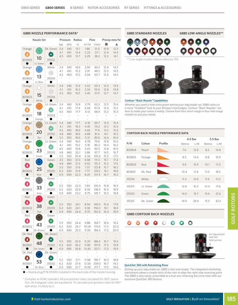
Visit hunterindustries.com 185GOLF IRRIGATION | Built on Innovation®
GO
LF R
OTO
RS
G900 SERIES G800 SERIES B SERIES ROTOR ACCESSORIES RT SERIES FITTINGS & ACCESSORIES
QuickSet-360 with Ratcheting Riser
Setting up your adjustable arc G885 is fast and simple. The integrated ratcheting mechanism allows a simple twist of the riser to align the right-side reversing point. The G885 is also easily convertible to a true non-reversing full circle rotor with our exclusive QuickSet-360 feature.
Contour “Back-Nozzle” Capabilities
Whether you want a little extra green behind your adjustable-arc G885 rotors or a more “modeled” look to your fairway’s hard edges, Contour “Back-Nozzles” are here to make your vision a reality. Choose from four short-range or four mid-range nozzles to suit your needs.
G885 STANDARD NOZZLES G885 LOW-ANGLE NOZZLES**
G885 CONTOUR BACK-NOZZLES
** Low-angle nozzles reduce radius by 15%
CONTOUR BACK-NOZZLE PERFORMANCE DATA
P/N Colour Profile4.5 Bar 5.5 Bar
Metres L/M Metres L/M
803604 Peach 7.6 12.9 8.2 14.8
803603 Orange 8.5 14.4 8.8 15.9
803602 Red 9.4 15.9 10.1 17.0
803601 Dk. Red 10.4 17.4 11.0 18.5
315314 White 11.3 10.6 11.6 11.0
315313 Lt. Green 12.8 16.3 13.4 17.8
315310 Green 14.0 19.7 14.6 21.6
315312 Dk. Green 14.9 29.9 15.5 33.3
Arc adjustment and riser hold-up tool
6
G885 NOZZLE PERFORMANCE DATA*
Nozzle Set Pressure Radius
m
Flow Precip mm/hr
bar kPa m3/hr l/min
Orange Dk. Green 3.4 340 13.1 1.86 31.0 10.8 12.54.1 410 13.4 2.23 37.1 12.4 14.3
10 4.5 450 13.7 2.29 38.2 12.2 14.1803603 315312 - - - - - - -
Lt. Green - - - - - - -Orange White 3.4 340 14.6 2.66 44.3 12.4 14.3
4.1 410 15.2 2.91 48.5 12.5 14.5
13 4.5 450 15.5 3.04 50.7 12.6 14.5803603 315314 - - - - - - -
Lt. Blue - - - - - - -Orange White 3.4 340 15.9 3.02 50.3 12.0 13.9
4.1 410 16.2 3.34 55.6 12.8 14.8
15 4.5 450 16.5 3.45 57.5 12.7 14.7803603 315314 - - - - - - -
White - - - - - - -Orange Lt. Green 3.4 340 16.8 3.79 63.2 13.5 15.6
4.1 410 17.4 4.04 67.4 13.4 15.5
18 4.5 450 17.7 4.13 68.9 13.2 15.3803603 315313 - - - - - - -
Orange - - - - - - -Orange Lt. Green 3.4 340 17.7 4.18 69.7 13.4 15.4
4.1 410 18.3 4.45 74.2 13.3 15.4
20 4.5 450 18.6 4.66 77.6 13.5 15.6803603 315313 4.8 480 18.6 4.88 81.4 14.1 16.3
Tan 5.5 550 18.9 5.13 85.6 14.4 16.6Orange Lt. Green 3.4 340 18.6 4.78 79.6 13.8 16.0
4.1 410 19.2 5.18 86.3 14.0 16.2
23 4.5 450 19.8 5.43 90.5 13.8 16.0803603 315313 4.8 480 20.1 5.86 97.7 14.5 16.7
Green 5.5 550 20.4 6.34 105.6 15.2 17.5Red Green 4.5 450 21.0 6.68 111.3 15.1 17.4
4.8 480 21.3 6.92 115.3 15.2 17.6
25 5.5 550 21.6 7.37 122.8 15.7 18.2803602 315310 6.2 620 21.9 7.77 129.5 16.1 18.6
Blue 6.9 690 22.3 8.25 137.4 16.7 19.2Red Green - - - - - - -
- - - - - - -
33 5.5 550 22.3 7.83 130.4 15.8 18.3803602 315310 6.2 620 22.6 8.34 138.9 16.4 18.9
Grey 6.9 690 23.2 8.75 145.7 16.3 18.8Red Green - - - - - - -
- - - - - - -
38 5.5 550 24.1 8.94 149.0 15.4 17.8803602 315310 6.2 620 24.1 9.36 156.0 16.1 18.6
Red 6.9 690 24.4 9.75 162.4 16.4 18.9Red Green - - - - - - -
- - - - - - -
43 5.5 550 24.4 9.88 164.7 16.6 19.2803602 315310 6.2 620 24.7 10.54 175.6 17.3 20.0
Dk. Brown 6.9 690 25.3 11.06 184.3 17.3 20.0Dk. Red Dk. Green - - - - - - -
- - - - - - -
48 5.5 550 25.9 11.20 186.6 16.7 19.3803601 315312 6.2 620 26.2 11.86 197.6 17.3 19.9
Dk. Green 6.9 690 26.8 12.43 207.1 17.3 19.9Dk. Red Dk. Green - - - - - - -
- - - - - - -
53 5.5 550 27.1 11.98 199.7 16.3 18.8803601 315312 6.2 620 27.4 12.54 209.0 16.7 19.2
Dk. Blue 6.9 690 27.7 13.06 217.7 17.0 19.6
= Nozzle plug P/N 315300 installed in the back side of the nozzle housing.
* Complies to ASAE standard. All precipitation rates calculated for 360° opera-tion. All triangular rates are equilateral. To calculate precipitation rates for 180° operation, multiply by 2.

Visit hunterindustries.com186
GO
LF RO
TOR
S
G835EPop-up height: 8 cmOverall height: 30 cm Flange diameter: 18 cmFemale Inlet: 1½" ACME
G835CPop-up height: 8 cmOverall height: 30 cm Flange diameter: 18 cmFemale Inlet: 1½" ACME
FEATURES• Model: G835: Full/Part circle (50º to 360°)• QuickCheck™ arc mechanism• QuickSet-360 arc mechanism• Nozzle choices: 8 multi-trajectory (15° to 25°)• Nozzle range: #2 to #12• Water lubricated gear-drive
► All TTS advanced features ► Decoder-In-Head (DIH) capable
OPERATING SPECIFICATIONS• Radius: 5.5 to 15.2 m • Flow: 0.43 to 2.91 m3/hr; 7.2 to 48.5 l/min• Pressure range: 2.8 to 4.5 bar; 280 to 450 kPa• All TTS rotors are pressure rated at 10 bar; 1,000 kPa
OPTIONS• C – Check-O-Matic checks up to 8 m in elevation change and readily
converts to Normally-Open Hydraulic with through the top connections• D – Decoder Valve-In-Head with all “E” specifications below*• DD – Two-station Decoder Valve-In-Head with all “E” specifications below*• E – Electric Valve-In-Head with adjustable pressure regulation, on-off-auto
selector, 210 mA (370 mA inrush) 50Hz; 190 mA (350 mA inrush) 60Hz solenoid with captive plunger and internal downstream bleed
* All DIH rotors include two 3M DBRY-6 splices for connection to the 2-wire path. See page 205 for critical recommendations on grounding DIH rotors.
► = TTS and DIH Advanced Features detailed on pages 174 and 176
Model: G835Radius: 5.5 to 15.2 mFlow: 0.43 to 2.91 m3/hr; 7.2 to 48.5 l/minG800 SERIES
G900 SERIES G800 SERIES B SERIES ROTOR ACCESSORIES RT SERIES FITTINGS & ACCESSORIES
G835 – SPECIFICATION BUILDER: ORDER 1 + 2 + 3 + 4 + 5
1 Model 2 Valve Options 3 Nozzle 4 Regulation* 5 Options
G835 = Full/Part Circle 50 to 360° C = Check-O-Matic * 6 = Installed G835 Nozzle * includes 8-nozzle rack
P5 = 50 PSI S = SSU *
D = Decoder Valve-in-Head
E = Electric Valve-in-Head
* Converts to N.O. Hydraulic Valve-in-Head
P6 = 65 PSI
* SSU = #6 * SSU = P5 * Standard Stocking Unit
Examples: G835E - 6 - P5 - S = G835 full/part-circle electric valve-in-head, installed #6 nozzle, 50 PSI regulation, standard stocking unit model

Visit hunterindustries.com 187GOLF IRRIGATION | Built on Innovation®
GO
LF R
OTO
RS
QuickSet-360
With Hunter’s QuickCheck arc mechanism and patented QuickSet-360 non-reversing full-circle feature in a variable arc rotor, adjustments are fast, easy and more flexible than ever before. Now available on all B Series and G800 Series adjustable arc rotors.
G900 SERIES G800 SERIES B SERIES ROTOR ACCESSORIES RT SERIES FITTINGS & ACCESSORIES
G835 NOZZLE PERFORMANCE DATA*
Nozzle Pressure Radius m
Flow Precip mm/hr bar kPa m3/hr l/min
22.8 280 5.5 0.43 7.2 14.3 16.63.4 340 6.1 0.48 7.9 12.8 14.8
Yellow 4.1 410 6.7 0.55 9.1 12.1 14.04.5 450 7.0 0.59 9.8 12.0 13.9
32.8 280 7.0 0.68 11.4 13.9 16.03.4 340 7.6 0.73 21.1 12.5 14.5
Yellow 4.1 410 8.2 0.80 13.2 11.7 13.64.5 450 8.5 0.82 13.6 11.2 13.0
42.8 280 7.6 0.89 14.8 15.3 17.63.4 340 8.5 0.93 15.5 12.8 14.8
Yellow 4.1 410 9.1 1.00 16.7 12.0 13.84.5 450 9.4 1.04 17.4 11.7 13.5
52.8 280 8.8 1.07 17.8 13.7 15.83.4 340 9.8 1.14 18.9 11.9 13.8
Yellow 4.1 410 10.1 1.20 20.1 11.9 13.74.5 450 10.7 1.23 20.4 10.8 12.4
62.8 280 9.8 1.36 22.7 14.3 16.53.4 340 10.7 1.43 23.8 12.6 14.5
Yellow 4.1 410 11.3 1.50 25.0 11.8 13.64.5 450 11.9 1.54 25.7 10.9 12.6
82.8 280 11.0 1.77 29.5 14.7 17.03.4 340 11.9 1.82 30.3 12.9 14.8
Yellow 4.1 410 12.8 1.89 31.4 11.5 13.34.5 450 13.1 1.93 32.2 11.2 13.0
102.8 280 11.9 2.20 36.7 15.6 18.03.4 340 13.1 2.29 38.2 13.4 15.4
Yellow 4.1 410 13.7 2.34 39.0 12.4 14.44.5 450 14.3 2.39 39.7 11.6 13.4
122.8 280 13.4 2.73 45.4 15.2 17.53.4 340 14.3 2.77 46.2 13.5 15.6
Yellow 4.1 410 14.6 2.84 47.3 13.3 15.34.5 450 15.2 2.91 48.5 12.5 14.5
G835 NOZZLES
in 1

Visit hunterindustries.com188
GO
LF RO
TOR
S
FEATURES• Full circle opposing nozzles • Colour-coded nozzles: 7 standard trajectory (25°) • Nozzle range: #23 to #53• Exclusive PressurePort™ nozzle technology• Water lubricated gear-drives• Check height up to 3 m in elevation change
OPERATING SPECIFICATIONS• Radius: 20.4 to 26.8 m• Flow: 5.11 to 13.15 m3/hr; 85.2 to 219.2 l/min • Pressure range: 4.5 to 6.9 bar; 450 to 690 kPa • All B Series rotors are pressure rated at 10 bar; 1,000 kPa
Models: G80BRadius: 20.4 to 26.8 mFlow: 5.11 to 13.15 m3/hr; 85.2 to 219.2 l/minB SERIES
G80BPop-up height: 8 cmOverall height: 24.5 cm Flange diameter: 13.7 cm Female Inlet: 1¼" ACME
G900 SERIES G800 SERIES B SERIES ROTOR ACCESSORIES RT SERIES FITTINGS & ACCESSORIES
G80B – SPECIFICATION BUILDER: ORDER 1 + 2 + 3 + 4
1 Model 2 Valve Options 3 Nozzle 4 Options*
G80 = Full Circle B = Block rotor with check valve 23 to 53 = Installed G80 Nozzle* S = SSU*
* SSU = #23, #25 or #48 * Standard Stocking Unit
Example: G80 - B - 25 - S = G80 full circle block rotor, installed #25 nozzle, standard stocking unit model
Table of Contents:B Series
Cross References:

Visit hunterindustries.com 189GOLF IRRIGATION | Built on Innovation®
GO
LF R
OTO
RS
G900 SERIES G800 SERIES B SERIES ROTOR ACCESSORIES RT SERIES FITTINGS & ACCESSORIES
G80B NOZZLE PERFORMANCE DATA*
Nozzle Pressure Radius m
Flow Precip mm/hr bar kPa m3/hr l/min
234.5 450 20.4 5.11 85.2 12.3 14.14.8 480 21.0 5.43 90.5 12.3 14.2
Green 5.5 550 21.6 5.91 98.4 12.6 14.6
6.2 620 21.9 6.34 105.6 13.2 15.26.9 690 22.3 6.77 112.8 13.7 15.8
254.5 450 21.6 6.54 109.0 14.0 16.14.8 480 22.3 6.79 113.2 13.7 15.8
Blue 5.5 550 22.6 7.29 121.5 14.3 16.5
6.2 620 22.9 7.79 129.8 14.9 17.26.9 690 23.2 8.18 136.3 15.2 17.6
334.5 450 22.3 7.04 117.3 14.2 16.44.8 480 22.6 7.31 121.9 14.4 16.6
Grey 5.5 550 23.2 7.88 131.4 14.7 17.0
6.2 620 23.5 8.40 140.1 15.3 17.66.9 690 23.8 8.81 146.9 15.6 18.0
384.5 450 23.2 7.97 132.9 14.9 17.24.8 480 23.5 8.25 137.4 15.0 17.3
Red 5.5 550 24.1 8.75 145.7 15.1 17.4
6.2 620 24.4 9.20 153.3 15.5 17.96.9 690 24.7 9.75 162.4 16.0 18.5
434.5 450 23.8 8.90 148.4 15.8 18.24.8 480 24.1 9.27 154.4 16.0 18.5
Dk. Brown 5.5 550 25.0 9.93 165.4 15.9 18.3
6.2 620 25.3 10.56 176.0 16.5 19.16.9 690 25.6 11.09 184.7 16.9 19.5
484.5 450 25.0 9.95 165.8 15.9 18.44.8 480 25.3 10.52 175.3 16.4 19.0
Dk. Green 5.5 550 25.9 11.13 185.5 16.6 19.1
6.2 620 26.2 11.79 196.5 17.2 19.86.9 690 26.5 12.36 205.9 17.6 20.3
534.5 450 25.3 10.65 177.5 16.6 19.24.8 480 25.6 11.15 185.9 17.0 19.6
Dk. Blue 5.5 550 26.5 11.95 199.1 17.0 19.6
6.2 620 26.8 12.45 207.4 17.3 20.06.9 690 26.8 13.15 219.2 18.3 21.1
* Complies to ASAE standard. All precipitation rates calculated for 360° operation. All triangular rates are equilateral.
G80B NOZZLES
G80B

Visit hunterindustries.com190
GO
LF RO
TOR
S
FEATURES• Models:
- G84B: Full circle opposing nozzles - G85B: True full circle/adjustable part circle (60° to 360°)
• QuickCheck™ arc mechanism (G85B)• QuickSet-360 arc mechanism (G85B)• Dual trajectory colour-coded nozzles:
- G84B: 10 standard trajectory (22.5°) - G85B: 12 standard trajectory (22.5°)
• G84B & G85B: 9 low-angle trajectory (15°)• Nozzle range:
- G84B: #15 to #53 - G85B: #10 to #53
• Exclusive PressurePort™ nozzle technology• Contour “Back-Nozzle” capabilities (G85B)• Ratcheting stainless steel riser• Water lubricated gear-drives• Check height up to 3 m in elevation change
OPERATING SPECIFICATIONS• G84B
- Radius: 14.9 to 28.3 m - Flow: 3.28 to 13.24 m3/hr; 54.6 to 220.6 l/min - Pressure range: 3.4 to 6.9 bar; 340 to 690 kPa
• G85B - Radius: 13.1 to 27.7 m - Flow: 1.86 to 13.06 m3/hr; 31,0 to 217.7 l/min - Pressure range: 3.4 to 6.9 bar; 340 to 690 kPa
• All B Series rotors are pressure rated at 10 bar; 1,000 kPa
Models: G84B & G85BRadius: 13.1 to 28.3 mFlow: 1.86 to 13.24 m3/hr; 31.0 to 220.6 l/minB SERIES
G85BPop-up height: 9.5 cmOverall height: 24.5 cm Flange diameter: 13.7 cmFemale Inlet: 1¼" ACME
G84BPop-up height: 9.5 cmOverall height: 24.5 cm Flange diameter: 13.7 cmFemale Inlet: 1¼" ACME
G900 SERIES G800 SERIES B SERIES ROTOR ACCESSORIES RT SERIES FITTINGS & ACCESSORIES
G84B & G85B – SPECIFICATION BUILDER: ORDER 1 + 2 + 3 + 4
1 Model 2 Valve Options 3 Nozzle 4 Options*
G84 = Full Circle B = Block rotor with check valve 15 to 53 = Installed G84 Nozzle* S = SSU*
* SSU = #18, #25 & #48 * Standard Stocking Unit
G85 = Full/Part Circle 60° - 360° B = Block rotor with check valve 10 to 53 = Installed G85 Nozzle** S = SSU*
* * SSU = #18, #25 & #48 * Standard Stocking Unit
Example: G84 - B - 25 - S = G80 full circle block rotor, installed #25 nozzle, standard stocking unit model

Visit hunterindustries.com 191GOLF IRRIGATION | Built on Innovation®
GO
LF R
OTO
RS
G84B NOZZLE PERFORMANCE DATA*
Nozzle Set Pressure Radius m
Flow Precip mm/hr bar kPa m3/hr l/min
3.4 340 14.9 3.28 54.6 14.7 17.0Tan Grey 4.1 410 15.5 3.65 60.8 15.1 17.4
15 4.5 450 15.9 3.81 63.5 15.2 17.54.8 480 16.2 3.90 65.1 15.0 17.3
803611 White 315317 5.5 550 16.8 4.13 68.9 14.7 17.03.4 340 16.8 3.97 66.1 14.1 16.3
Tan Grey 4.1 410 17.1 4.28 71.3 14.7 17.0
18 4.5 450 17.4 4.45 74.1 14.7 17.04.8 480 18.0 4.66 77.6 14.4 16.6
803611 Orange 315317 5.5 550 18.6 4.94 82.4 14.3 16.53.4 340 17.4 3.91 65.2 13.0 15.0
Tan Grey 4.1 410 18.6 4.28 71.3 12.4 14.3
20 4.5 450 18.9 4.47 74.4 12.5 14.44.8 480 19.2 4.67 77.9 12.7 14.6
803611 Brown 315317 5.5 550 19.5 5.02 83.6 13.2 15.23.4 340 19.2 4.49 74.8 12.2 14.1
Tan Lt. Blue 4.1 410 19.8 4.99 83.2 12.7 14.7
23 4.5 450 20.1 5.19 86.5 12.8 14.84.8 480 20.4 5.41 90.1 13.0 15.0
803611 Green 315311 5.5 550 20.4 5.81 96.9 13.9 16.14.5 450 21.6 6.50 108.3 13.9 16.0
Tan Lt. Blue 4.8 480 22.3 6.75 112.5 13.6 15.7
25 5.5 550 22.6 7.19 119.8 14.1 16.36.2 620 22.9 7.65 127.5 14.6 16.9
803611 Blue 315311 6.9 690 22.9 8.12 135.3 15.5 17.94.5 450 22.3 7.02 117.0 14.2 16.4
Tan Lt. Blue 4.8 480 22.9 7.30 121.7 14.0 16.1
33 5.5 550 23.2 7.81 130.1 14.6 16.86.2 620 23.5 8.24 137.3 15.0 17.3
803611 Grey 315311 6.9 690 24.1 8.65 144.1 14.9 17.24.5 450 22.9 7.96 132.6 15.2 17.6
Tan Lt. Blue 4.8 480 23.2 8.29 138.1 15.4 17.8
38 5.5 550 23.8 8.85 147.5 15.7 18.16.2 620 24.1 9.38 156.3 16.2 18.7
803611 Red 315311 6.9 690 25.0 9.87 164.4 15.8 18.2- - - - - - -
Tan Blue - - - - - - -
43 5.5 550 25.3 9.85 164.1 15.4 17.86.2 620 25.9 10.52 175.3 15.7 18.1
803611 Dk. Brown 315300 6.9 690 26.5 11.04 183.9 15.7 18.1- - - - - - -
Dk. Brown Dk. Blue - - - - - - -
48 5.5 550 25.9 10.88 181.2 16.2 18.76.2 620 27.1 11.46 191.0 15.6 18.0
803610 Dk. Green 833500 6.9 690 27.7 12.08 201.4 15.7 18.1- - - - - - -
Dk. Brown Dk. Blue - - - - - - -
53 5.5 550 27.1 11.86 197.7 16.1 18.66.2 620 27.7 12.58 209.6 16.3 18.9
803610 Dk. Blue 833500 6.9 690 28.3 13.24 220.6 16.5 19.0
G900 SERIES G800 SERIES B SERIES ROTOR ACCESSORIES RT SERIES FITTINGS & ACCESSORIES
LOW-ANGLE NOZZLES**
** Low-angle nozzles reduce radius by 15%
G85B NOZZLES G84B NOZZLES
G85B NOZZLE PERFORMANCE DATA
Nozzle Set Pressure Radius
m
Flow Precip mm/hr
bar kPa m3/hr l/min
Orange Dk. Green 3.4 340 13.1 1.86 31.0 10.8 12.54.1 410 13.4 2.23 37.1 12.4 14.3
10 4.5 450 13.7 2.29 38.2 12.2 14.1803603 315312 - - - - - - -
Lt. Green - - - - - - -Orange White 3.4 340 14.6 2.66 44.3 12.4 14.3
4.1 410 15.2 2.91 48.5 12.5 14.5
13 4.5 450 15.5 3.04 50.7 12.6 14.5803603 315314 - - - - - - -
Lt. Blue - - - - - - -Orange White 3.4 340 15.9 3.02 50.3 12.0 13.9
4.1 410 16.2 3.34 55.6 12.8 14.8
15 4.5 450 16.5 3.45 57.5 12.7 14.7803603 315314 - - - - - - -
White - - - - - - -Orange Lt. Green 3.4 340 16.8 3.79 63.2 13.5 15.6
4.1 410 17.4 4.04 67.4 13.4 15.5
18 4.5 450 17.7 4.13 68.9 13.2 15.3803603 315313 - - - - - - -
Orange - - - - - - -Orange Lt. Green 3.4 340 17.7 4.18 69.7 13.4 15.4
4.1 410 18.3 4.45 74.2 13.3 15.4
20 4.5 450 18.6 4.66 77.6 13.5 15.6803603 315313 4.8 480 18.6 4.88 81.4 14.1 16.3
Tan 5.5 550 18.9 5.13 85.6 14.4 16.6Orange Lt. Green 3.4 340 18.6 4.78 79.6 13.8 16.0
4.1 410 19.2 5.18 86.3 14.0 16.2
23 4.5 450 19.8 5.43 90.5 13.8 16.0803603 315313 4.8 480 20.1 5.86 97.7 14.5 16.7
Green 5.5 550 20.4 6.34 105.6 15.2 17.5Red Green 4.5 450 21.0 6.68 111.3 15.1 17.4
4.8 480 21.3 6.92 115.3 15.2 17.6
25 5.5 550 21.6 7.37 122.8 15.7 18.2803602 315310 6.2 620 21.9 7.77 129.5 16.1 18.6
Blue 6.9 690 22.3 8.25 137.4 16.7 19.2Red
Green - - - - - - -
- - - - - - -
33 5.5 550 22.3 7.83 130.4 15.8 18.3803602 315310 6.2 620 22.6 8.34 138.9 16.4 18.9
Grey 6.9 690 23.2 8.75 145.7 16.3 18.8Red Green - - - - - - -
- - - - - - -
38 5.5 550 24.1 8.94 149.0 15.4 17.8803602 315310 6.2 620 24.1 9.36 156.0 16.1 18.6
Red 6.9 690 24.4 9.75 162.4 16.4 18.9Red Green - - - - - - -
- - - - - - -
43 5.5 550 24.4 9.88 164.7 16.6 19.2803602 315310 6.2 620 24.7 10.54 175.6 17.3 20.0
Dk. Brown 6.9 690 25.3 11.06 184.3 17.3 20.0Dk. Red Dk. Green - - - - - - -
- - - - - - -
48 5.5 550 25.9 11.20 186.6 16.7 19.3803601 315312 6.2 620 26.2 11.86 197.6 17.3 19.9
Dk. Green 6.9 690 26.8 12.43 207.1 17.3 19.9Dk. Red Dk. Green - - - - - - -
- - - - - - -
53 5.5 550 27.1 11.98 199.7 16.3 18.8803601 315312 6.2 620 27.4 12.54 209.0 16.7 19.2
Dk. Blue 6.9 690 27.7 13.06 217.7 17.0 19.6
= Nozzle plug P/N 315300 installed in the back side of the nozzle housing.
* Preliminary performance data.

Visit hunterindustries.com192
GO
LF RO
TOR
S
B SERIES
FEATURES• Models:
- G70B: Full circle - G75B: Full/Part circle (50° to 360°)
• QuickCheck™ arc mechanism (G75B)• QuickSet-360 arc mechanism (G75B)• Nozzle choices:
- G70B: 6 standard trajectory (25°) - G75B: 9 standard trajectory (25°)
• Nozzle range: - G70B: #15 to #28 - G75B: #8 to #28
• Exclusive PressurePort™ nozzle technology• Water lubricated gear-drive• Check height up to 3 m in elevation change
OPERATING SPECIFICATIONS• G70B
- Radius: 16.2 to 22.9 m - Discharge rate: 2.95 to 7.66 m3/hr; 49.2 to 127.6 l/min - Pressure range: 3.4 to 6.9 bar; 340 to 690 kPa
• G75B - Radius: 14.3 to 21.6 m - Discharge rate: 1.75 to 7.34 m3/hr; 29.1 to 122.3 l/m - Pressure range: 2.8 to 6.9 bar; 280 to 690 kPa
• All B Series rotors are pressure rated at 10 bars; 1,000 kPa
Models: G70B & G75B Radius: 14.3 to 22.9 mFlow: 1.75 to 7.66 m3/hr; 29.1 to 127.6 l/min
G75BPop-up height: 8 cmOverall height: 23 cm Flange diameter: 12cmFemale Inlet: 1¼" ACME
G70BPop-up height: 8 cmOverall height: 23 cm Flange diameter: 12 cmFemale Inlet: 1¼" ACME
G900 SERIES G800 SERIES B SERIES ROTOR ACCESSORIES RT SERIES FITTINGS & ACCESSORIES
G70B & G75B - SPECIFICATION BUILDER: ORDER 1 + 2 + 3 + 4
1 Model 2 Valve Options 3 Nozzle 4 Options
G70 = Full Circle B = Block Rotor with Check Valve 25 = Installed G70 Nozzle *S = SSU *
* Available in SSU model only SSU = #25 Includes nozzle pack
* Standard Stocking Unit
G75 = Full/Part Circle, 50° - 360° Arc Range
B = Block Rotor with Check Valve 25 = Installed G75 Nozzle ** S = SSU *
** Available in SSU model only SSU = #25 Includes nozzle pack
* Standard Stocking Unit
Example: G70 - B - 25 - S = G70 full circle block rotor, installed #25 nozzle with nozzle pack, standard stocking unit model

Visit hunterindustries.com 193GOLF IRRIGATION | Built on Innovation®
GO
LF R
OTO
RS
G900 SERIES G800 SERIES B SERIES ROTOR ACCESSORIES RT SERIES FITTINGS & ACCESSORIES
G70B NOZZLE PERFORMANCE DATA*
Nozzle Pressure Radius m
Flow Precip mm/hr bar kPa m3/hr l/min
153.4 340 16.2 2.95 49.2 11.3 13.14.1 410 16.5 3.20 53.4 11.8 13.7
Grey 4.5 450 16.8 3.36 56.0 12.0 13.8
4.8 480 17.1 3.52 58.7 12.1 14.05.5 550 17.7 3.70 61.7 11.8 13.7
183.4 340 17.7 3.23 53.8 10.3 11.94.1 410 18.0 3.61 60.2 11.2 12.9
Red 4.5 450 18.3 3.70 61.7 11.1 12.8
4.8 480 18.3 3.84 64.0 11.5 13.35.5 550 18.6 4.04 67.4 11.7 13.5
203.4 340 18.6 4.27 71.2 12.4 14.34.1 410 18.9 4.45 74.2 12.5 14.4
Dk. Brown 4.5 450 19.2 4.66 77.6 12.6 14.6
4.8 480 19.5 5.00 83.3 13.1 15.25.5 550 19.5 5.32 88.6 14.0 16.1
233.4 340 19.2 4.57 76.1 12.4 14.34.1 410 19.8 4.77 79.5 12.2 14.0
Dk. Green 4.5 450 19.8 4.97 82.9 12.7 14.6
4.8 480 20.1 5.32 88.6 13.1 15.25.5 550 20.4 5.66 94.3 13.6 15.7
253.4 340 19.8 4.95 82.5 12.6 14.64.1 410 20.4 5.11 85.2 12.3 14.1
Dk. Blue 4.5 450 20.4 5.36 89.3 12.9 14.8
4.8 480 21.0 5.75 95.8 13.0 15.05.5 550 21.6 6.11 101.8 13.0 15.1
284.8 480 21.6 6.38 106.4 13.6 15.75.5 550 21.6 6.79 113.2 14.5 16.7
Black 6.2 620 22.3 7.22 120.4 14.6 16.86.9 690 22.9 7.66 127.6 14.6 16.9
* Complies to ASAE standard. All precipitation rates calculated for 360° operation. All triangular rates are equilateral. To calculate precipitation rates for 180° operation, multiply by 2.
G75B NOZZLE PERFORMANCE DATA*
Nozzle Pressure Radius m
Flow Precip mm/hr bar kPa m3/hr l/min
82.8 280 14.3 1.75 29.1 8.5 9.83.4 340 14.9 1.89 31.4 8.5 9.8
Lt. Brown 4.1 410 15.2 2.09 34.8 9.0 10.4
4.5 450 15.2 2.16 36.0 9.3 10.74.8 480 15.5 2.25 37.5 9.3 10.7
103.4 340 16.2 2.48 41.3 9.5 11.04.1 410 16.5 2.73 45.4 10.1 11.6
Lt. Green 4.5 450 16.5 2.84 47.3 10.5 12.1
4.8 480 16.8 2.98 49.6 10.6 12.25.5 550 17.1 3.25 54.1 11.1 12.9
133.4 340 16.8 2.54 42.4 9.1 10.54.1 410 17.1 2.79 46.6 9.6 11.1
Lt. Blue 4.5 450 17.1 2.91 48.5 10.0 11.5
4.8 480 17.4 3.02 50.3 10.0 11.65.5 550 17.4 3.25 54.1 10.8 12.4
153.4 340 17.4 3.04 50.7 10.1 11.64.1 410 17.7 3.25 54.1 10.4 12.0
Grey 4.5 450 18.0 3.36 56.0 10.4 12.0
4.8 480 18.0 3.48 57.9 10.7 12.45.5 550 18.3 3.73 62.1 11.2 12.9
183.4 340 18.3 3.29 54.9 9.8 11.44.1 410 18.6 3.57 59.4 10.3 11.9
Red 4.5 450 18.6 3.70 61.7 10.7 12.4
4.8 480 18.9 3.84 64.0 10.7 12.45.5 550 19.2 4.13 68.9 11.2 12.9
204.1 410 18.9 4.04 67.4 11.3 13.14.5 450 18.9 4.13 68.9 11.6 13.4
Dk. Brown 4.8 480 19.2 4.36 72.7 11.8 13.7
5.5 550 19.5 4.66 77.6 12.2 14.16.2 620 19.8 4.95 82.5 12.6 14.6
234.1 410 19.5 4.97 82.9 13.1 15.14.5 450 19.8 4.86 81.0 12.4 14.3
Dk. Green 4.8 480 19.8 5.36 89.3 13.7 15.8
5.5 550 20.1 5.82 96.9 14.4 16.66.2 620 20.4 6.13 102.2 14.7 17.0
254.1 410 19.8 5.34 89.0 13.6 15.74.5 450 19.8 5.63 93.9 14.4 16.6
Dk. Blue 4.8 480 20.4 5.82 96.9 13.9 16.1
5.5 550 21.0 6.20 103.3 14.0 16.26.2 620 21.6 6.59 109.8 14.1 16.2
284.8 480 20.1 6.11 101.8 15.1 17.45.5 550 20.7 6.56 109.4 15.3 17.6
Black 6.2 620 21.3 6.95 115.8 15.3 17.66.9 690 21.6 7.34 122.3 15.7 18.1
G70B & G75B NOZZLES
G70B
G75B

Visit hunterindustries.com194
GO
LF RO
TOR
S
FEATURES• Model: G35B: Full/Part Circle (50º - 360º)• QuickCheck™ arc mechanism• QuickSet-360 arc mechanism• Nozzle choices:
- 8 multi-trajectory 15°–25°• Nozzle range:
- #2 to #12• Water lubricated gear-drive• Check height up to 3 m in elevation change
OPERATING SPECIFICATIONS• Radius: 5.5 to 15.2 m• Flow: 0.43 to 2.91m3/hr; 7.2 to 48.5 l/min • Pressure range: 2.8 to 4.5 bar; 280 to 450 kPa • All B Series rotors are pressure rated at
10 bar; 1,000 kPa
Model: G35B Radius: 5.5 to 15.2 mFlow: 0.43 to 2.91 m3/hr; 7.2 to 48.5 l/minB SERIES
G35BPop-up height: 8 cmOverall height: 23 cm Flange diameter: 12 cmFemale Inlet: 1¼" ACME
G900 SERIES G800 SERIES B SERIES ROTOR ACCESSORIES RT SERIES FITTINGS & ACCESSORIES
G35B – SPECIFICATION BUILDER: ORDER 1 + 2 + 3 + 4
1 Model 2 Valve Options 3 Nozzle 4 Options*
G35 = Full/Part Circle 50º to 360º B = Block rotor with check valve 6 = Installed G35 Nozzle* S = SSU*
* Available in SSU model only SSU = #6 Includes nozzle rack
* Standard Stocking Unit
Example: G35 - B - 6 - S = G35 full/part circle block rotor, installed #6 nozzle with nozzle rack, standard stocking unit model

Visit hunterindustries.com 195GOLF IRRIGATION | Built on Innovation®
GO
LF R
OTO
RS
HQ5LRC Quick Coupler
with HSJ-1 SnapLok™ equipped swing joint
Introducing Hunter’s new full line of HSJ heavy-duty swing joints with configurations for every need and every project. There is even a version specifically designed for quick coupler applications. The SnapLok outlet on HSJ-1 models come equipped with accommodations for both rebar and pipe stabilisation, as well as heavy-duty brass outlet threads with a unique anti-rotation locking feature.
See the HSJ swing joints on page 44
G900 SERIES G800 SERIES B SERIES ROTOR ACCESSORIES RT SERIES FITTINGS & ACCESSORIES
G835 NOZZLE PERFORMANCE DATA*
Nozzle Pressure Radius m
Flow Precip mm/hr bar kPa m3/hr l/min
22.8 280 5.5 0.43 7.2 14.3 16.63.4 340 6.1 0.48 7.9 12.8 14.8
Yellow 4.1 410 6.7 0.55 9.1 12.1 14.04.5 450 7.0 0.59 9.8 12.0 13.9
32.8 280 7.0 0.68 11.4 13.9 16.03.4 340 7.6 0.73 21.1 12.5 14.5
Yellow 4.1 410 8.2 0.80 13.2 11.7 13.64.5 450 8.5 0.82 13.6 11.2 13.0
42.8 280 7.6 0.89 14.8 15.3 17.63.4 340 8.5 0.93 15.5 12.8 14.8
Yellow 4.1 410 9.1 1.00 16.7 12.0 13.84.5 450 9.4 1.04 17.4 11.7 13.5
52.8 280 8.8 1.07 17.8 13.7 15.83.4 340 9.8 1.14 18.9 11.9 13.8
Yellow 4.1 410 10.1 1.20 20.1 11.9 13.74.5 450 10.7 1.23 20.4 10.8 12.4
62.8 280 9.8 1.36 22.7 14.3 16.53.4 340 10.7 1.43 23.8 12.6 14.5
Yellow 4.1 410 11.3 1.50 25.0 11.8 13.64.5 450 11.9 1.54 25.7 10.9 12.6
82.8 280 11.0 1.77 29.5 14.7 17.03.4 340 11.9 1.82 30.3 12.9 14.8
Yellow 4.1 410 12.8 1.89 31.4 11.5 13.34.5 450 13.1 1.93 32.2 11.2 13.0
102.8 280 11.9 2.20 36.7 15.6 18.03.4 340 13.1 2.29 38.2 13.4 15.4
Yellow 4.1 410 13.7 2.34 39.0 12.4 14.44.5 450 14.3 2.39 39.7 11.6 13.4
122.8 280 13.4 2.73 45.4 15.2 17.53.4 340 14.3 2.77 46.2 13.5 15.6
Yellow 4.1 410 14.6 2.84 47.3 13.3 15.34.5 450 15.2 2.91 48.5 12.5 14.5
G835 NOZZLES
* Complies to ASAE standard. All precipitation rates calculated for 360° operation. All triangular rates are equilateral. To calculate precipitation rates for 180° operation, multiply by 2.

Visit hunterindustries.com196
GO
LF RO
TOR
S
G80RTPop-up height: 8 cm
G70RT / G75RTPop-up height: 8 cm
FEATURES• Models:
- G70RT: Full circle riser with nozzle set - G75RT: Full/Part circle riser with nozzle set - G80RT: Full circle riser with nozzle set
• Works with all 1" and 1½" inlet Toro® 600 and 700 Series golf rotors• Converts current sprinklers into closed-case rotors• The RT upgrade extends the life of existing irrigation systems• Performance, reliability and long life• Upgrade takes less than 5 minutes
Models: G70RT, G75RT & G80RT Radius: 14.3 to 26.8 mFlow: 1.75 to 13.15 m3/hr; 29.1 to 219.2 l/minRT SERIES
Quick and Easy Upgrade!
The RT retro upgrade takes just minutes and extends the life and reliability of aging irrigation systems.
G900 SERIES G800 SERIES B SERIES ROTOR ACCESSORIES RT SERIES FITTINGS & ACCESSORIES
G70RT/G75RT RETRO RISERS
To Replace Use Hunter Model/NozzleTORO® Nozzle G70RT
Full CircleG75RT
Full/Part Circle
630
31 15 15
32 18 18
33 20 20
34 28 –
660
62 15 15
63 18 18
64 25 25
65 28 –
730
31 15 15
32 18 18
33 20 20
34 23 23
35 28 –
760
62 15 15
63 18 18
64 20 23
65 25 25
66 28 –
G80RT RETRO RISERS
To Replace Use Hunter Model/NozzleTORO® Nozzle G80RT
Full Circle
650
56 23
57 33
58 33
59 38
67070 43
71 48
72 48
680
84 25
85 3386 3387 43
88 48
750
54 25
55 33
56 38
57 43
58 48
780
84 25
85 25
86 33
87 38
88 43
89 48
Table of Contents:RT Series
Cross References:

Visit hunterindustries.com 197GOLF IRRIGATION | Built on Innovation®
GO
LF R
OTO
RS
Visit hunterindustries.com 197GOLF IRRIGATION | Built on Innovation®
ACME ADAPTER FITTINGS
1¼" Models1¼" male ACME x 1" female NPT P/N 109325
1¼" male ACME x 1" female BSP P/N 105329
1¼" male ACME x 1¼" female NPT P/N 474800
1¼" male ACME x 1¼" female BSP P/N 474900
1¼" male ACME x 1½" female NPT P/N 104153
1¼" male ACME x 1½" female BSP P/N 107262
1½" Models1½" male ACME x 1" female NPT P/N 475400
1½" male ACME x 1" female BSP P/N 475500
1½" male ACME x 1¼" female NPT P/N 475200
1½" male ACME x 1¼" female BSP P/N 475300
1½" male ACME x 1½" female NPT P/N 475000
1½" male ACME x 1½" female BSP P/N 475100
Acme x Acme Models1½" male ACME x 1" ACME female P/N 225300
1½" male ACME x 1¼" ACME female P/N 225400
1¼" male ACME x 1" ACME female P/N 225500
B2B Tee Assembly1½" ACME threaded tee and 1½" adapter for connecting
two swing joints to a single mainline connection in
back-to-back installations around greens.
P/N = HSJ-305-015-3 = NPT Inlet
P/N = HSJ-305-015-6 = BSP Inlet
P/N = HSJ-305-015-M = ACME Inlet (shown)
G900 SERIES G800 SERIES B SERIES ROTOR ACCESSORIES RT SERIES FITTINGS & ACCESSORIES
ROTOR ACCESSORIES
Hose Swivel Adapters
Rubber Cover Kit
HOSE-SWIVEL ADAPTERS
Models• Hose swivel adapter for G90 and G900 Series (fits ¾" & 1" hose) P/N G90HS100• Hose swivel adapter for G800 Series (fits ¾" & 1" hose) P/N G800HS100
RUBBER COVER KITS
Models• G990 rubber cover kit (date codes 06/11 & prior only) P/N 473800• G995 rubber cover kit (also G990 date codes 07/11 & after) P/N 473900
Cross References:ACME Adapter Fittings
Rotor Accessories

198
CENTRAL CONTROL
CEN
TRA
L CO
NTR
OL
SECTION 12:
Table of Contents:Golf Central ControlGolf Central Control
Cross References:

199
CENTRAL CONTROL
CEN
TRA
L C
ON
TRO
L
PILOT-DH DECODER HUB EASY TO PROGRAM AND MAINTAIN
PILOT-CC SOFTWARE CENTRAL CONTROL PILOT-FC FIELD CONTROLLER
Pilot includes a two-wire decoder option. Pilot-DH decoder hubs have a 999-station capacity and can run up to 120 stations simultaneously.
The hub has a plastic pedestal enclosure with a full-featured control panel. It can be used as in-field control, a stand-alone decoder controller, or linked to a Pilot-CC central control for fully flow-optimised irrigation management.
Communication options include hardwire, UHF radio, and two spread-spectrum bands. Power options include both 120 and 230 VAC.
Ease-of-Use: The control panel features a large, multi-language display and an array of function buttons providing quick access to the most commonly used features. The display clearly shows what the controller is doing and has a unique feature which shows the user what time the next scheduled watering will occur.
Ease-of-Maintenance: The system was designed with you in mind. Circuit boards are encapsulated in polyurethane to reduce damage from moisture and pests. All hardware is captured, so you won’t lose screws in the grass. The clean, modular design of Pilot units allow them to be serviced with a Phillips screwdriver, which we provide with every controller.
Safely balance sprinkler demand with water and electrical supply for the most efficient irrigation cycles possible.
The Pilot field controller manages up to 80 stations in 10 station increments. The full-featured controller has everything you need in a stand-alone field controller. For a fully automated, flow-optimised system, network all your controllers together with Pilot-CC central control software.
Communication options include hardwire, UHF radio, and two spread-spectrum bands. Power options include both 120 VAC and 230 VAC.
PILOT® CENTRAL CONTROLADVANCED FEATURESCOMPLETE CONTROL

Visit hunterindustries.com200
CEN
TRA
L CO
NTR
OL
Overview - Pilot
PILOT® SOFTWARE
Pilot is easy to use and has all the features you need to reliably and automatically water your course. Runtimes can be adjusted manually or determined automatically using application depth. Irrigation is scheduled through a powerful programming matrix which lets you see every sprinkler on the course while you make your adjustments. Pilot offers two types of water management, flow optimised and FCP or field controller program. When flow-optimised, electrical and hydraulic demand are efficiently managed to ensure your watering window is as short as possible. When you use an FCP you have total control over when, where and how long sprinklers run—perfect for overseeding, seed germination, grow-in and other cultural practices where optimal use of the pump station is a secondary concern. FCPs can be retrieved into the central control software, edited, then sent back to the field unit – so you can manage all your controller schedules from the computer in your office.
PILOT SOFTWARE SPECIFICATIONS• Operating system: 64-bit Windows® 8• Maximum field controllers: 999• Maximum stations: 79,920• ET-based scheduling: weather station or manually entered• Hydraulic management: automated and graphed to individual stations• Mapping: online maps converted from AutoCAD and other applications
* Note: Windows is a registered trademark of The Microsoft® Corporation
PILOT® SOFTWARE PILOT® CONTROLLER PILOT® DECODERS WEATHER STATION MAINTENANCE RADIO ICD-HP
Table of Contents:Pilot® Software
Cross References:

Visit hunterindustries.com 201GOLF IRRIGATION | Built on Innovation®
CEN
TRA
L C
ON
TRO
L
MANAGE THE FLOWPilot® uses your electrical and hydraulic data to efficiently balance sprinkler demand while maintaining flow at safe velocities. To protect your pump station and maintain optimal sprinkler uniformity, irrigation can be gradually stepped up in safe increments.
CREATE AND EDIT SCHEDULES OUT ON THE COURSEWith Pilot, critical irrigation is not dependent upon the whims and availability of a computer or communications link where it is subject to a single point of failure. Pilot software creates schedules then sends them to the field where controllers do the actual irrigating. Because Pilot field controllers are packed with intelligence, you can even create and edit schedules out on the course and transfer them back to Pilot for review and editing.
MAPPING YOUR COURSEAlthough it is not required to have a map, adding one allows you to run waterby clicking the station symbols on the map, monitor stations as they arerunning, and adjust certain settings.
Flow Optimisation
PILOT® SOFTWARE PILOT® CONTROLLER PILOT® DECODERS WEATHER STATION MAINTENANCE RADIO ICD-HP
Maps
Schedule Creation

Visit hunterindustries.com202
CEN
TRA
L CO
NTR
OL
FEATURES• 5 languages• Up to 80 station outputs in
10-station increments• Up to 3 Hunter golf valve-in-head
rotors per station output• Up to 20 simultaneous Hunter
golf valve-in-head rotors active per controller
• 32 automatic schedules with 8 start times per schedule
• Exclusive Safe-Toggle™ mechanical on-off-auto station switches
• 1–31 day skip-day scheduling• One-touch rain shutdown up to 30
days or indefinitely• One-touch Safe-Pause™ with 30
minute safety timer• 1–300% runtime seasonal adjustment• Seasonal start time adjustment is
used to quickly change all start times plus or minus 30 minutes
POWER SUPPLY INPUT• 120/230 VAC at 60/50 Hz• 1.2 Amps maximum at 120 VAC• 0.73 Amps maximum at 230 VAC
POWER SUPPLY OUTPUT• Station output: 1 Amp at 24 VAC• 24 VAC Hot Post output: 420 mA at 24 VAC• Solenoid Capacity: 3 standard 24 VAC Hunter golf valve-in-head rotors per
output, 20 maximum simultaneous stations
RADIO SYSTEMS• UHF Radio: 450-470 MHz; other frequeny ranges available for selected
markets• Spread Spectrum Radio: 915 MHz
WIRED SYSTEMS• GCBL: Shielded two twisted pairs, 0.82 mm²• GCBLA: Armored, shielded two twisted pairs, 0.82 mm²
Application: Golf Number of Stations: 80Type: Field ControllerPILOT® CONTROLLER
Pilot-FC Plastic PedestalHeight: 100 cm Width: 60 cm Depth: 44 cm Weight: 32 kg
Pilot-FI Field InterfaceOne is required with any central control system. It is used to link the central computer to the field equipment. For indoor locations only.
Height: 30 cm Width: 30 cm Depth: 11 cm Weight: 2 kg
PILOT-FI – SPECIFICATION BUILDER ORDER 1 + 2 + 3
1 Model 2 Standard Features 3 Options
Pilot-FI Plastic pedestal (grey)
HWR Hardwire communications
UHF UHF radio communications (where permitted, licence required)
LF Licence-free radio communications
Examples:Pilot-FI-HWR = Field interface with hardwire communicationsPilot-FI-UHF = Field interface with UHF radio communications (US only)
PILOT® SOFTWARE PILOT® CONTROLLER PILOT® DECODERS WEATHER STATION MAINTENANCE RADIO ICD-HP
Table of Contents:Pilot® Controller
Cross References:Systems Pilot Controller

Visit hunterindustries.com 203GOLF IRRIGATION | Built on Innovation®
CEN
TRA
L C
ON
TRO
L
THE PILOT® FIELD CONTROLLER WAS BUILT SPECIFICALLY FOR GOLF COURSE IRRIGATION CONTROL.
Water-Resistant KeypadLarge backlit display with convenient
function buttons for the most commonly used features. Built-in
system diagnostics make trouble-shooting your system a breeze.
Easy to ServiceThe only tool required is a Phillips screwdriver included with every controller.
Modular 10-Station Expansion Boards Colour-coded modular components with captured screws so they won’t get lost, making it easy to assemble and troubleshoot.
Spacious Wiring Area No exposed circuitry or loose wires.All circuit boards are encapsulated in polyurethane to protect them from moisture, insects and temperature extremes.
Auto/On/Off Switches and Diagnostic LED Indicators
Standard for all station outputs, provide quick troubleshooting
and watering tools.
Conveniently Located Dual-Voltage (120/230 VAC) Junction Box
Features heavy duty surge protection and even includes a spare fuse.
PILOT-FC – SPECIFICATION BUILDER ORDER 1 + 2 + 3
1 Model 2 Standard Features 3 Options
Pilot-FC20 (20-station) S Stand-alone field controller with no central communications
Pilot-FC30 (30-station) HWR Hardwire communications
Pilot-FC40 (40-station) UHF UHF radio communications (where permitted, licence required)
Pilot-FC50 (50-station) Plastic pedestal (grey) LF Licence-free spread spectrum radio communications (900 MHz for North America and where permitted)
Pilot-FC60 (60-station)120/230 VAC 60/50 Hz dual-voltage transformer
Pilot-FC70 (70-station)
Pilot-FC80 (80-station)
Examples:Pilot-FC40-S = 40-station, stand-alone field contraoller with no central communicationsPilot-FC70-HWR = 70-station field controller with hardwire communications
PILOT® SOFTWARE PILOT® CONTROLLER PILOT® DECODERS WEATHER STATION MAINTENANCE RADIO ICD-HP

Visit hunterindustries.com204
CEN
TRA
L CO
NTR
OL
Decoder installations continue to be one of the fastest growing forms of technology in irrigation control. A key advantage over conventional systems is that decoders use less wire for an overall irrigation system. That means lower cost, quicker installation time, and easier system diagnosis and repair if needed. Systems can be easily expanded—with minimal digging and disruption of landscaping—by adding in more decoders rather than running additional wires.
Pilot enables you to take advantage of this cost-efficient approach. Pilot decoders are available with 1, 2, 4 and 6-station outputs, making it possible to run each head on an entire green with a single decoder. In all, decoders let you operate up to 999 stations out to 4.5 km from a single hub.
Pilot decoder systems include built-in surge suppression, colour-coded wire connections, true independent station control, programmable station addresses, and two-way feedback to the controller with confirmation and status indication.
Pilot-SG surge protectors are required when a system is designed and installed with Decoder-In-Head (DIH) rotors.
PILOT® DECODERS Application: GolfNumber of Stations: 999 Type: Decoder System
Water-Resistant KeypadBacklit display and secondary LED facepack means it can be used day or night
Diagnostic LED IndicatorsFor all functions on decoder output module
250-Station Output Modules Enable your decoder hub to grow with your course. Start with 250 - grow to 999
Pilot Decoder Hub
Pilot Decoders1 & 2 Station Decoders: Height: 9 cm Width: 4 cm Depth: 2.5 cm Weight: 150 g 4 & 6 Station Decoders: Height: 9 cm Width: 4.5 cm Depth: 4 cm Weight: 250 g Distinct yellow design makes it much easier to find decoders in dark valve boxes or buried in the soil.
All DIH rotors include two 3M DBRY-6 splices for connection to the 2-wire path. DIH rotor control systems require grounding with Pilot-SG surge suppressors coupled to appropriate grounding plate or rod. Hunter recommends a minimum of one Pilot-SG for every 12 installed DIH rotors or as per project specification.
DS-G Surge Ground Arrestor
PILOT® SOFTWARE PILOT® CONTROLLER PILOT® DECODERS WEATHER STATION MAINTENANCE RADIO ICD-HP
PILOT-DH – SPECIFICATION BUILDER ORDER 1 + 2 + 3
1 Model 2 Standard Features 3 Options
Pilot-DH250 (250-station) S Stand-alone decoder hub with no central communications
Pilot-DH500 (500-station) HWR Hardwire communications
Pilot-DH750 (750-station)Plastic pedestal (grey)
UHF UHF radio communications (where permitted, licence required)
Pilot-DH999 (999-station)LF Licence-free spread spectrum radio communications
(900 MHz for North America and where permitted)
Examples:Pilot-DH250-S = 250-station, stand-alone decoder hub with no central communicationsPilot-DH999-HWR = 999-station decoder hub with hardwire communications
Table of Contents:Pilot® Decoders
Cross References:

Visit hunterindustries.com 205GOLF IRRIGATION | Built on Innovation®
CEN
TRA
L C
ON
TRO
L
Decoder-In-HeadHunter’s exclusive DIH golf rotor minimises valve box covers on playing surface
Extend control up to 4,5 km with a single pair of wires
Decoder in valve box Runs up to 45 m from decoder to solenoids
Expansion options If your course has over 999 stations, you can use up to 999 decoder hubs for 998,001 decoders
Pilot-DHProvides independent station control of 999 decoders with up to 120 running simultaneously
Surge ProtectionDecoder-In-Head systems require approximately one Pilot surge arrestor for every 12 decoders. The actual number will vary by system design
Wireless Programming!
Communicate with decoders directly through plastic case: wireless electro-magnetic induction saves waterproof connectors
See the ICD-HP on page 207
PILOT® SOFTWARE PILOT® CONTROLLER PILOT® DECODERS WEATHER STATION MAINTENANCE RADIO ICD-HP
DECODERS – SPECIFICATION BUILDER ORDER 1
1 Model 2 Standard Features
Pilot-100 1-station decoder Built-in surge protection
Pilot-200 2-station decoder DBRY-6 Waterproof Connectors includedPilot-400 4-station decoder
Pilot-600 6-station decoder
Pilot-SG Inline surge protection (for DIH rotor systems)
Example:Pilot-100 = 1-station decoder
Cross References:DBRY Ref

Visit hunterindustries.com206
CEN
TRA
L CO
NTR
OL
FEATURES• Includes built-in 60-day data logger: With onboard evapotranspiration (ET)
calculation (modified Penman-Monteith equation for turf grass)• Wireless package uses 2.4 GHz licence-free technology
- 2.4 GHz radio systems can reach up to 3 km - In rural areas, try the licence-free, 900 MHz radio for links up to 800 m
• Wired systems use Hunter GCBL, direct-bury cable with a range of 1.25 km (dedicated 9-pin serial computer port required)
• Optional solar panel kit provides wireless power - Simple installation and versatile mounting with on-board 800 mAh rechargeable gel cell battery with 18 VDC transformer and 7 m power cable.
• Weatherproof construction: With UV stabilised enclosure, weather-proof external connectors and long-life coated circuit boards
• UL, c-UL and CE certifications
TurfWeather StationHeight: 61 cm Width: 40.5 cm Depth: 38 cm Weight: 6 kg
Application: GolfRange: Wireless 1 kmType: Weather StationWEATHER STATION
PILOT® SOFTWARE PILOT® CONTROLLER PILOT® DECODERS WEATHER STATION MAINTENANCE RADIO ICD-HP
COMPLETE PACKAGES INCLUDE HUNTER WEATHER SOFTWARE
Model Description
TWHW Wired communications to central computer – GCBL cable is required
TW24 2.4 GHz licence-free radio communication to central computer
TW916 916 MHz licence-free radio communication to central computer
TW922A 922 MHz licence-free radio communication to central computer
TWSUN Optional solar power kit for all TurfWeather models
Table of Contents:Weather Station
Cross References:

Visit hunterindustries.com 207GOLF IRRIGATION | Built on Innovation®
CEN
TRA
L C
ON
TRO
L
FEATURES• Instant control of stations, blocks and programs• Fewer buttons to push• Instant audio confirmation of commands• Hunter’s famous StraightTalk™ Technology: Enables wireless
remote control at ranges up to 3.5 km whether or not the central computer is turned on
• Easy commands that show in display before sending• Compact size, industrial construction• Suitable for two-way voice communication with crews and office• High signal output: 2 watts, UHF (450–470 MHz)*
* Note: Licence required in most countries
TRNR RadioHeight: 10.25 cm Width: 5.25 cm Depth: 3 cm Weight: 200 grams
Application: GolfRange: Up to 3.5 kmType: Remote ControlMAINTENANCE RADIO
FEATURES• Program or re-program decoder stations, whether new or installed• Program any station numbers in any order, or skip stations for
future expansion• Turn decoder stations on and view solenoid status, current in milliamps,
and more• Built-in voltmeter for decoder path• Communicates with decoders directly through plastic case: wireless
electro-magnetic induction saves waterproof connectors• Communicates through the top of DIH rotors- no cover
removal required
Type: Decoder ProgrammerICD-HP
ICD-HP
WIRELESS HANDHELD DECODER PROGRAMMER
ICD-HPHeight: 21 cm Width: 9 cm Depth: 5 cm
Packaged in an outdoor carrying case, this complete kit includes probes, induction cup, cable, USB power cable for bench use, and 4 AA batteries for field work.
PILOT® SOFTWARE PILOT® CONTROLLER PILOT® DECODERS WEATHER STATION MAINTENANCE RADIO ICD-HP
Cross References:Maintenance Radio
ICD-HP

TECH
NIC
AL
208
TECHNICAL INFORMATION
SECTION 13:Table of Contents:Technical Information
Cross References:

TEC
HN
ICA
L
209
TECHNICAL INFORMATION
SECTION 13:

210
TECH
NIC
AL
HUNTER Technical Services
Contact Us
Phone: 1-800-733-2823, Mon–Fri 6 a.m.–4 p.m. PST
Email: [email protected]
After Hours: Leave us a voice message and someone
from our team will return your call the next business day
Online Product Information
Visit our Support Library for instructional videos, owner’s manuals, installation details, articles, and more.
Rotors, Controllers, Sensors, Drip/Micro Irrigation, Valves, Sprays, Nozzles, FX Luminaire, and Water Management Software
www.hunterindustries.com/support
Anyone can sell you products. At Hunter, we’ve always believed the difference lies in providing world-class product support to make your job easier. When you need technical help, whether it’s to ask a quick question or to get product-specific troubleshooting assistance, you can count on Hunter’s Technical Services Team to provide the best support in the industry. Our knowledgeable experts are always available to help you.
In addition, our Field Service Team provides on-site training and troubleshooting assistance with central control, decoder system, and other commercial, residential, municipal, and golf course installations. Their combined experience of 200+ years in the industry is invaluable when you need factory support by phone, remote desktop, or at the job site.
Our Hunter Technical Service Team has more
than 197 years of combined industry expertise.
Table of Contents:Technical Services
Cross References:

211
TEC
HN
ICA
L
To get started:
1. Access the training website:
• Visit www.training.hunterindustries.com• Log in or create a new account• Click on courses, enroll at no cost, watch the training module,
and take the quiz
2. Take courses for the level you choose:
• Click on the Specialist Program and choose the level you need• Click on the courses required for each level and enroll in
the courses• Watch the training module and take the quiz
3. Apply for your certificate:
• Submit the Completion Notification Form for each level• Obtain your certificate and use your membership card. You
may use your certificates to apply for Continuing Education Unit Credits through the Irrigation Association
PRODUCT Specialist Program
This unique training program is designed
to equip contractors, distributors, and other
professionals with the knowledge to become
familiar with Hunter products.
Choose from three levels of training:
Technician Level: Basic knowledge of the entire Hunter product line
Specialist Level: In-depth knowledge on a particular product
Expert Level: Thorough knowledge on a product category
Cross References:Specialist Program

212
TECHNICAL INFORMATION
TECH
NIC
AL
REPLACEMENT GUIDEBringing together a combination of intelligent design, carefully controlled manufacturing, and regular testing to ensure conformity to the strictest standards, Hunter has been able to create truly exceptional nozzles. Essentially, we have made the science of developing superior nozzles—and thus, superior sprinklers—look easy. In the process, we have also made it easy for you to determine which of these high performance sprinklers can be used to replace other brands. Simply consult the following replacement guide to find the appropriate Hunter sprinkler for any irrigation need.
PGP® GEAR DRIVEN ROTARY SPRINKLERS
To ReplaceRAIN BIRD®
Use Hunter Nozzle Red Blue
Mini-Paw 15103 07 (Black) 6 2.509 (Green) 7 3.0
Maxi-Paw 2045 06 (Red) 5 2.007 (Black) 6 2.508 (Blue) 8 4.0
10 (Yellow) 9 5.012 (Beige) 10 8.0
R-50 1.5 (Black) 5 2.02.0 (Brown) 7 3.03.0 (Grey) 8 4.0
4.0 (Yellow) 9 5.06.0 (Green) 10 8.0
T-Bird T-30 1.3 (Black) 4 1.52.5 (Grey) 6 2.5
5.0 (Green) 9 5.05000 1.5 4 1.5
2.0 5 2.03.0 7 3.04.0 8 4.06.0 9 5.08.0 10 8.0
5505 2 5 2.03 6 2.54 7 3.05 8 4.06 9 5.08 10 8.010 10 8.012 11 8.0
To ReplaceK-RAIN®
Use Hunter Nozzle Red Blue
RPS75 0.50 1 - -0.75 2 - -1.0 4 1.52.0 6 2.02.5 7 2.53.0 8 3.04.0 9 4.06.0 10 6.08.0 11 8.0
PGP® GEAR DRIVEN ROTARY SPRINKLERS
To ReplaceTORO®
Use Hunter Nozzle Red Blue
300/340 308-XX-02 4 1.5Stream Rotor 308-XX-03 7 3.0
316-XX-02 7 3.0316-XX-03 10 8.0
XP-300 Series XP-300-090-07 4 1.5180-07 7 3.0360-07 10 8.0
XP-300-090-09 5 2.0180-09 8 4.0360-09 11 - -
XP-300-090-10 5 2.0180-10 9 5.0360-10 12 - -
Super 600 1.3 4 1.52.5 7 3.05.0 10 8.06.0 10 8.0
Super 700 1.3 3 1.51.5 4 1.52.0 5 2.03.0 7 3.04.5 8 4.06.0 9 5.07.5 10 8.09.0 11 8.0
Super 800 0.50 1 - -0.75 2 - -1.0 4 1.52.0 6 2.02.5 7 2.53.0 8 3.04.0 9 4.06.0 10 6.08.0 11 8.0
TR50 1.0 3 - -1.5 4 1.52.0 5 2.03.0 6 3.04.5 8 4.06.0 9 6.07.5 10 8.09.0 11 8.0
PGJ GEAR DRIVEN ROTARY SPRINKLERS
To ReplaceRAIN BIRD®
Use Hunter Nozzle Red
3500 0.75 0.751 1.0
1.5 1.52 2.03 3.04 4.0
T-Bird T-22 .65 (Blue) 0.751.0 (Red) 1.0
1.3 (Black) 1.52.0 (Brown) 2.0
2.5 (Grey) 2.54.0 (Yellow) 4.0
T-Bird T-30 1.0 (Red) 1.01.3 (Black) 1.5
2.0 (Brown) 2.02.5 (Grey) 2.5
4.0 (Yellow) 4.05.0 (Green) 5.0
To ReplaceTORO®
Use Hunter Nozzle Red
300/340 1 0.75Stream Rotor 2 1.5
3 3.0
To ReplaceNELSON®
Use Hunter Nozzle Red
5500 #51 0.75#52 1.5#53 2.0#54 2.5
Table of Contents:Replacement Guide
Cross References:

213
TECHNICAL INFORMATION
TEC
HN
ICA
L
REPLACEMENT GUIDE
PGP® ULTRA / I-20 GEAR DRIVEN ROTARY SPRINKLERS
To ReplaceRAIN BIRD®
Use Hunter Nozzle Blue
Mini-Paw 15103 07 (Black) 2.509 (Green) 3.0
Maxi-Paw 2045 06 (Red) 2.007 (Black) 2.508 (Blue) 4.0
10 (Yellow) 5.012 (Beige) 8.0
R-50 1.5 (Black) 2.02.0 (Brown) 3.03.0 (Grey) 4.0
4.0 (Yellow) 5.06.0 (Green) 8.0
T-Bird T-30 1.3 (Black) 1.52.5 (Grey) 2.5
5.0 (Green) 5.05000 1.5 1.5
2.0 2.03.0 3.04.0 4.06.0 5.08.0 8.0
5505 2 2.03 2.54 3.05 4.06 5.08 8.010 8.012 8.0
To ReplaceK-RAIN®
Use Hunter Nozzle Blue
RPS75 0.50 - -0.75 - -1.0 1.52.0 2.02.5 2.53.0 3.04.0 4.06.0 6.08.0 8.0
PGP® ULTRA / I-20 GEAR DRIVEN ROTARY SPRINKLERS
To ReplaceTORO®
Use Hunter Nozzle Blue
300/340 308-XX-02 1.5Stream Rotor 308-XX-03 3.0
316-XX-02 3.0316-XX-03 8.0
XP-300 Series XP-300-090-07 1.5180-07 3.0360-07 8.0
XP-300-090-09 2.0180-09 4.0360-09 - -
XP-300-090-10 2.0180-10 5.0360-10 - -
Super 600 1.3 1.52.5 3.05.0 8.06.0 8.0
Super 700 1.3 1.51.5 1.52.0 2.03.0 3.04.5 4.06.0 5.07.5 8.09.0 8.0
Super 800 0.50 - -0.75 - -1.0 1.52.0 2.02.5 2.53.0 3.04.0 4.06.0 6.08.0 8.0
TR50 1.0 - -1.5 1.52.0 2.03.0 3.04.5 4.06.0 6.07.5 8.09.0 8.0
SPRAY SPRINKLERS
To ReplaceANY MFRS NOZZLES
Use Hunter ProductNozzles
Nozzles 2.4 m Radius 8A3.0 m Radius 10A3.7 m Radius 12A4.6 m Radius 15A5.2 m Radius 17A
Rain Bird 1800 Pro-Spray1800 SAM Pro-Spray-CV1800 SAM PRS Pro-Spray-PRS30-CVUni-Spray PS Ultra

214
TECHNICAL INFORMATION
TECH
NIC
AL
REPLACEMENT GUIDE
To ReplaceRAIN BIRD®
Use Hunter Nozzle
FALCON 4 (Black) 4 (Yellow)6 (Lt. Blue) 5 (White)
8 (Dk. Green) 7 (Orange)10 (Grey) 8 (Lt. Brown)12 (Beige) 10 (Lt. Green)
14 (Lt. Green) 13 (Lt. Blue)16 (Dk. Brown) 18 (Red)
18 (Dk. Blue) 20 (Dk. Brown)41-51A 18 x 11.5 20 (Dk. Brown)41-51A 13 x 11 13 (Lt. Blue)47A 16 13 (Lt. Blue)37A 14 8 (Lt. Brown)7005 4 (Black) 4 (Yellow)
6 (Lt. Blue) 5 (White)8 (Dk. Green) 8 (Lt. Brown)
10 (Grey) 10 (Lt. Green)12 (Beige) 13 (Lt. Blue)
14 (Lt. Green) 15 (Grey)16 (Dk. Brown) 18 (Red)
18 (Dk. Blue) 20 (Dk. Brown)8005 12 (Beige) 13 (Lt. Blue)
14 (Lt. Green) 15 (Grey)16 (Dk. Brown) 18 (Red)
18 (Dk. Blue) 20 (Dk. Brown)20 (Red) 23 (Dk. Green)
22 (Yellow) 25 (Dk. Blue)24 (Orange) 28 (Black)
To ReplaceTORO®
Use Hunter Nozzle
2001 6 (Yellow) 7 (Orange)9 (Red) 8 (Lt. Brown)
12 (Brown) 10 (Lt. Green)18 (Blue) 18 (Red)
24 (Green) 25 (Dk. Blue)640 40 8 (Lt. Brown)
41 10 (Lt. Green)42 13 (Lt. Blue)43 15 (Grey)44 20 (Dk. Brown)
To ReplaceNELSON®
Use Hunter Nozzle
7000 & 7500 1 7 (Orange)2 8 (Lt. Brown)3 10 (Lt. Green)4 13 (Lt. Blue)5 15 (Grey)6 20 (Dk. Brown)7 23 (Dk. Green)8 25 (Dk. Blue)
I-40 GEAR DRIVEN ROTARY SPRINKLERS
To ReplaceRAIN BIRD®
Use Hunter Nozzle
41-51A 18 x 11.5 23 (Dk. Green)41-51A 13 x 11 15 (Grey)47A-SAM 16 13 (Lt. Blue)37A 14 10 (Lt. Green)65 SERIES 16 13 (Lt. Blue)8005 12 (Beige) 10 (Lt. Green)
14 (Lt. Green) 15 (Grey)16 (Dk. Brown) 15 (Grey)
18 (Dk. Blue) 23 (Dk. Green)20 (Red) 25 (Dk. Blue)
22 (Yellow) 25 (Dk. Blue)TALON 14 13 (Lt. Blue)
16 10 (Lt. Green)18 23 (Dk. Green)20 25 (Dk. Blue)22 25 (Dk. Blue)
To ReplaceTORO®
Use Hunter Nozzle
640 40 8 (Lt. Brown)41 10 (Lt. Green)42 13 (Lt. Blue)43 15 (Grey)44 23 (Dk. Green)
To ReplaceTHOMPSON®
Use Hunter Nozzle
186/7 R-Nozzle 13 (Lt. Blue)S-Nozzle 15 (Grey)T-Nozzle 15 (Grey)
188/9 U-Nozzle 23 (Dk. Green)V-Nozzle 25 (Dk. Blue)

215
TECHNICAL INFORMATION
TEC
HN
ICA
L
REPLACEMENT GUIDE
HQ - QUICK COUPLERS
To ReplaceRAIN BIRD®
To ReplaceTORO®
To ReplaceBUCKNER
To ReplaceWEST AG/STORM
Use Hunter
3RC 075-SLSC QB3RC07 4V075-RY, QCV075-R HQ-3RC33DRC QB33RC07 4V133-4A-RY, QCV133-4A-R HQ-33DRC33DLRC QB33LRC07 4V133-4A-RLY, QCV133-4A-RL-2 HQ-33DLRC33DNP QB33NP07 4V133-4A-RL-NP, QVC133-4A-N-2 HQ-33DLRC-R44RC 100-SLSC, QB44RC10 4V144-RY, QCV-144-R HQ-44RC44LRC 100-2SLVC QB44LRC10 4V144-RLY, QCV-144-RL HQ-44LRC44NP 100-SLVLC QB44NO10 4V144-RL-NP, QCV-144-N HQ-44LRC-R
100-2SLLVC QB44RCATAR10 HQ-44RC-AWQB44LRCATAR10 HQ-44LRC-AW
4NP-Acme QB44NPATAR10 HQ-44LRC-AW-R5RC 100-ATLVC QBRB5RC10 4V101-RY, QCV-101-R HQ-5RC5LRC QBRB5LRC10 4V101-RLY, QCV-101-RL HQ-5LRC5NP QBRB5NP10 4V101-RL-NP, QCV-101-N HQ-5LRC-R5RC-BSP QBRB5RC10BS 4V101-RY-BS, QCV-101-R-BS HQ-5RC-BSP5LRC-BSP QBRB5LRC10BS 4V101-RLY-BS, QCV-101-RL-BS HQ-5LRC-BSP5NP-BSP QBRB5NP10BS 4V101-RL-NP-BS, QCV-101-N-BS HQ-5LRC-BSPR
HQ - KEYS
To ReplaceRAIN BIRD®
To ReplaceTORO®
To ReplaceBUCKNER
To ReplaceWEST AG/STORM
Use Hunter
33K, 33DK 075-SLK QB33K07 4C075, C075 HK-3344K 100-SLK QB44K10 4C100, C100 HK-444K-Acme 100-AK QB44KAT10 4C100A, C100A HK-44A55K-1 QB5RK10 4C101, C101 HK-55
HQ - SWIVELS
To ReplaceRAIN BIRD®
To ReplaceTORO®
To ReplaceBUCKNER
To ReplaceWEST AG/STORM
Use Hunter
SH-0 075-75MHS HS075 4HS-075, HS075 HS-0SH-1 075-MHS HS100 4HS-100, HS-100 HS-1SH-2 100-MHS HS101 4HS-101, HS-101 HS-2
HS100BS 4HS-100-BS, HS-100-BS HS-1-BHS101BS 4HS-101-BS, HS-101-BS HS-2-B

216
TECHNICAL INFORMATION
TECH
NIC
AL
PRECIPITATION RATES
In this section, the “Sprinkler Spacing Method–Any Arc and Any Spacing” equation is used to calculate precipitation rates. The first set of equations with the ■ shows the precipitation rate for the sprinklers when they are laid out in a square pattern. The next set with the ▲ shows the precipitation rate for the sprinklers laid out in an equilateral triangular spacing pattern. This is the “Sprinkler Spacing Method–Equilateral Triangular Spacing” equation.
WHAT IS PRECIPITATION RATE?
If someone said they were caught in a rainstorm that dropped 25mm of water in an hour, you would have some idea of how hard or heavily the rain came down. A rainstorm that covers an area with 25mm of water in one hour has a precipitation rate of one meter per hour (25 mm/hr). Similarly, the precipitation rate is the speed at which a sprinkler or an irrigation system applies water.
MATCHED PRECIPITATION RATES
A zone or system in which all the heads have similar precipitation rates is said to have “matched precipitation rates.” Systems that have matched precipitation rates reduce wet and dry spots and excessive run times, which lead to high water consumption and increased costs. Knowing that sprinkler spacing, flow rates, and arcs of coverage affect precipitation rates, a general guideline is: as the spray arc doubles, so should the flow.
90° Arc = 1 GPM; 0.23 m3/hr; 3.8 l/min
180° Arc = 2 GPM; 0.45 m3/hr; 7.6 l/min
360° Arc = 4 GPM; 0.91 m3/hr; 15.1 l/min
The flow rate of half-circle heads must be two times the flow rate of the quarter-circle heads, and the full-circle heads must have two times the flow rate of the half-circle heads. In the illustration, the same amount of water is applied to each quarter circle area and precipitation is therefore matched.
CALCULATING PRECIPITATION RATES
Depending upon the construction of the irrigation system, the precipitation rate may be calculated by either a Sprinkler Spacing or a Total Area method.
Sprinkler Spacing Method ()The precipitation rate should be calculated for each individual zone. If all sprinkler heads on the zone have the same spacing, flow rate, and arc of coverage, use one of the following formulas:
Any Arc and Any Spacing ():
P.R. (in/hr) = Flow Rate (GPM) for any Arc x 34,650Degrees of Arc x Head Spacing (ft.) x Row Spacing (ft.)
P.R. (mm/hr) = Flow Rate (m3/hr) for any Arc x 360,000Degrees of Arc x Head Spacing (m) x Row Spacing (m)
P.R. (mm/hr) = Flow Rate (l/min) for any Arc x 21,600Degrees of Arc x Head Spacing (m) x Row Spacing (m)
Sprinkler Spacing Method ()The precipitation rate should be calculated for each individual zone. If all sprinkler heads on the zone have the same spacing, flow rate, and arc of coverage, use one of the following formulas:
Equilateral Triangular Spacing ():
P.R. (in/hr) = Flow Rate (GPM) for any Arc x 34,650Degrees of Arc x (Head Spacing)2 x 0.866
P.R. (mm/hr) = Flow Rate (m3/hr) for any Arc x 360,000Degrees of Arc x (Head Spacing)2 x 0.866
P.R. (mm/hr) = Flow Rate (l/min) for any Arc x 21,600Degrees of Arc x (Head Spacing)2 x 0.866
Total Area Method The precipitation rate for a “system” is the average precipitation rate of all sprinklers in an area, regardless of the spacing, flow rate, or arc for each head. The Total Area Method calculates all the flows of all of the heads in any given area.
P.R. (in/hr) = Flow (GPM) x 96.25Total Area (ft.)
P.R. (mm/hr) = Flow (m3/hr) x 1,000Total Area (m2)
P.R. (mm/hr) = Flow (l/min) x 60Total Area (m2)
Table of Contents:Precipitation Rates
Cross References:

217
TECHNICAL INFORMATION
TEC
HN
ICA
L
SLOPE EQUIVALENTS/IRRIGATION
% RatioAngle
0˚0
10 10: 113 m
20 5: 16 m
30 13 m33 3: 15 m
50 2: 110 m
67 1.5: 115 m
100 1: 10 m
110
0.5
: 1
47˚
13
m
120
50˚
13 m
130
52˚
8 m
140
54˚
9 m
150
56˚
6 m
160
58˚
0 m
170
59˚
10 m
180
60˚
17 m
190
62˚
5 m
200
63˚
8 m
40 15 m
60 18 m
70 0 m
80 12 m
90 0 m
16˚
11˚
5˚
18˚
21˚
26˚
30˚33˚35˚
38˚
42˚
45˚
SLOPE IRRIGATION: Maximum precipitation rates for slopes in mm/hr
Soil Texture 0 to 5% Slope 5 to 8% Slope 8 to 12% Slope 12% + SlopeCover Bare Cover Bare Cover Bare Cover Bare
Coarse sandy soils 51 51 51 38 38 25 25 13
Coarse sandy soils over compact subsoils 44 38 32 25 25 19 19 10
Light sandy loams uniform 44 25 32 20 25 15 19 10
Light sandy loams over compact subsoils 32 19 25 13 19 10 13 8
Uniform silt loams 25 13 20 10 15 8 10 5
Silt loams over compact subsoil 15 8 13 6 10 4 8 3Heavy clay or clay loam 5 4 4 3 3 2 3 2
Notes:Maximum precipitation rates for slopes in mm/hrThe maximum precipitation values listed below are those suggested by the United States Department of Agriculture. The values are average and may vary with respect to actual soil condition and condition of ground cover.
Cross References:Slope Equivalents/Irrigation

218
TECHNICAL INFORMATION
TECH
NIC
AL
HEIGHT OF SPRAYThe trajectory and spray height of the water stream leaving a sprinkler nozzle is important information when designing and installing irrigation systems.
These rotor nozzle trajectory charts are designed to help determine how close a sprinkler can be placed to an object such as a fence or hedge without obstructing the spray pattern. All information shown is at optimum operating pressures.
HUNTER NOZZLE HEIGHT AND TRAJECTORY CHART
Model Nozzle No. Pressure Degrees of Trajectory
Max Height of Spray (m)
Distance from Head to Maximum Height (m)bar kPa
MP ROTATOR® 800 2.8 280 18 0.4 Varies1000 2.8 280 20 0.5 Varies
2000 2.8 280 26 1.1 Varies
3000 2.8 280 26 2.0 Varies
3500 2.8 280 28 2.5 Varies
Corner 2.8 280 14 0.4 Varies
Side Strip 2.8 280 16 0.5 VariesLeft Strip 2.8 280 16 0.5 Varies
PGJ 0.75 2.8 280 10 0.6 1.21.0 2.8 280 10 0.6 2.4
1.5 2.8 280 10 0.9 3.7
2.0 2.8 280 15 1.5 4.9
2.5 2.8 280 12 1.5 6.1
3.0 2.8 280 15 1.5 6.1
4.0 2.8 280 15 1.5 6.75.0 2.8 280 15 1.8 7.3
PGP® RED NOZZLES
1.0 3.5 350 26 2.1 6.72.0 3.5 350 26 2.1 6.7
3.0 3.5 350 26 2.4 7.0
4.0 3.5 350 26 2.4 7.0
5.0 3.5 350 27 2.7 7.9
6.0 3.5 350 27 3.0 8.5
7.0 3.5 350 26 3.4 9.1
8.0 3.5 350 26 3.4 9.1
9.0 3.5 350 27 3.7 9.8
10.0 4.0 400 25 4.0 9.8
11.0 4.0 400 25 4.0 11.612.0 4.0 400 25 4.0 12.2
PGP LOW ANGLE GREY NOZZLES
4.0 3.5 350 15 1.5 6.75.0 3.5 350 15 1.2 6.7
6.0 3.5 350 14 1.2 6.7
7.0 3.5 350 14 1.2 6.7
8.0 3.5 350 14 1.5 7.3
9.0 3.5 350 15 1.5 7.910.0 4.0 400 15 1.8 9.1
PGP BLUE NOZZLES
1.5 3.0 300 25 2.4 7.02.0 3.0 300 25 2.4 7.0
2.5 3.0 300 25 2.7 7.9
3.0 3.0 300 25 3.0 8.5
4.0 3.0 300 25 3.4 9.1
5.0 3.0 300 25 3.4 9.1
6.0 3.8 380 25 3.7 9.88.0 3.8 380 25 4.0 9.8
PGP ULTRA/I-20DARK BLUENOZZLES
1.0 3.5 350 26 2.4 7.01.5 3.5 350 26 2.4 7.0
2.0 3.5 350 27 2.7 7.9
3.0 3.5 350 27 3.0 8.5
3.5 3.5 350 26 3.4 9.1
4.0 3.5 350 26 3.4 9.1
6.0 3.5 350 27 3.7 9.88.0 4.0 400 25 4.0 9.8
PGP ULTRA/I-20BLUE NOZZLES
1.5 3.0 300 25 2.4 7.02.0 3.0 300 25 2.4 7.0
2.5 3.0 300 25 2.7 7.9
3.0 3.0 300 25 3.0 8.5
4.0 3.0 300 25 3.4 9.1
5.0 3.0 300 25 3.4 9.1
6.0 3.8 380 25 3.7 9.88.0 3.8 380 25 4.0 9.8
Table of Contents:Height of Spray
Cross References:

219
TECHNICAL INFORMATION
TEC
HN
ICA
L
HEIGHT OF SPRAYHUNTER NOZZLE HEIGHT AND TRAJECTORY CHART
Model Nozzle No. Pressure Degrees of Trajectory
Max Height of Spray (m)
Distance from Head to Maximum Height (m)bar kPa
PGP® Ultra/I-20 Low Angle Grey Nozzles
2.0 LA 3.5 350 13 1.5 6.72.5 LA 3.5 350 13 1.2 6.73.5 LA 3.5 350 13 1.2 6.74.5 LA 3.5 350 13 1.2 6.7
PGP Ultra/I-20 Short Radius Black Nozzles
0.5 3.5 350 15 1.5 2.41.0 3.5 350 14 1.8 2.72.0 3.5 350 3 0.3 1.8
PGP Ultra/I-20 Short Radius Black Nozzles
0.75 3.5 350 22 2.1 4.01.5 3.5 350 18 2.1 4.03.0 3.5 350 8 0.3 1.8
PGP Ultra/I-20 MPR-25 Red Nozzles
Q - 90 3.0 300 22 0.9 4.6T - 120 3.0 300 21 1.2 4.2H - 180 3.0 300 24 1.2 4.2F - 360 3.0 300 22 1.2 3.0
PGP Ultra/I-20 MPR-30 Lt. Green Nozzles
Q - 90 3.0 300 28 1.5 5.4T - 120 3.0 300 14 0.9 5.1H - 180 3.0 300 16 1.2 4.8F - 360 3.0 300 18 0.6 3.9
PGP Ultra/I-20 MPR-35 Tan Nozzles
Q - 90 3.0 300 28 1.8 5.7T - 120 3.0 300 28 1.8 5.4H - 180 3.0 300 16 1.2 5.1F - 360 3.0 300 14 0.9 3.6
I-25 4 3.5 350 25 2.7 6.75 3.5 350 25 3.4 8.57 3.5 350 25 3.0 8.58 3.5 350 25 3.4 8.510 4 400 25 3.7 9.113 4 400 25 4.0 9.415 4 400 25 3.7 9.418 4 400 25 4.6 10.420 5 500 25 4.6 10.723 5 500 25 4.9 11.625 5 500 25 4.9 11.628 5 500 25 5.2 12.2
I-40 8 (40) 3.5 350 25 3.7 9.810 (41) 4 400 25 4.3 9.813 (42) 4 400 25 4.3 10.415 (43) 4 400 25 4.6 12.823 (44) 5 500 25 5.2 14.025 (45) 5 500 25 5.2 14.6
I-90 ADV 33 5.5 550 22 4.6 12.838 5.5 550 22 4.9 14.643 5.5 550 22 4.9 14.648 5.5 550 22 5.2 16.553 5.5 550 22 5.2 17.163 5.5 550 22 5.5 19.5
I-90 36V 33 5.5 550 22 5.2 14.038 5.5 550 22 5.2 15.243 5.5 550 22 5.2 16.548 5.5 550 22 5.2 17.153 5.5 550 22 5.2 17.763 5.5 550 22 5.5 18.9
I-90 ADV Low Angle
33 5.5 550 15 2.4 11.538 5.5 550 15 2.7 12.143 5.5 550 15 2.7 12.548 5.5 550 15 3.0 13.153 5.5 550 15 3.4 13.763 5.5 550 15 3.7 14.6
I-90 36V Low Angle
33 5.5 550 15 2.4 11.538 5.5 550 15 2.7 12.143 5.5 550 15 2.7 12.548 5.5 550 15 3.0 13.153 5.5 550 15 3.4 13.763 5.5 550 15 3.7 14.6

220
TECHNICAL INFORMATION
TECH
NIC
AL
DRIP CONTROL ZONE KIT CHARTSR
equi
red
dyna
mic
pre
ssur
e in
bar
Design ow in litres per minute
PCZ 2.7 bar
PCZ 1.7 bar
0200 40 60 80
1
2
3
4
5
6
PCZ101: Inlet pressure required for designed outlet pressure
MINI LANDSCAPE DRIPLINE FLOW CHART
Req
uire
d dy
nam
ic p
ress
ure
in b
ar
Design ow in litres per hour
01.00.50 2.01.5 3.02.5 3.5
0.50
1.00
1.50
2.00
2.50
3.00
3.50
MLD
16 MM EMITTER LINE MAX LENGTH – 2.2 l/hr
Pressure(bar)
Emitter Spacing (m)
0.30 0.50
1.0 47 73
2.0 84 1313.0 104 162
16 MM EMITTER LINE MAX LENGTH – 3.8 l/hr
Pressure(bar)
Emitter Spacing (m)
0.30 0.50
1.0 35 54
2.0 59 913.0 72 112
17 MM EMITTER LINE MAX LENGTH – 1.5 l/hr
Pressure(bar)
Emitter Spacing (m)
0.30 0.50 0.60
1.0 86 119 149
2.0 132 185 2323.0 159 223 281
17 MM EMITTER LINE MAX LENGTH – 2.2 l/hr
Pressure(bar)
Emitter Spacing (m)
0.30 0.50 0.60
1.0 51 71 88
2.0 89 124 1563.0 108 152 191
17 MM EMITTER LINE MAX LENGTH – 3.8 l/hr
Pressure(bar)
Emitter Spacing (m)
0.30 0.50 0.60
1.0 37 52 65
2.0 65 92 1153.0 80 112 142
EMITTER LINE MAXIMUM RUN LENGTH
Table of Contents:Micro Irrigation Charts
Cross References:PCZ RefMLD Flow ChartPLD Ref

221
TECHNICAL INFORMATION
TEC
HN
ICA
L
16 MM EMITTER FLOW RATE – 2.2 l/hr
Row Spacing (m)
Emitter Spacing (m)
0.30 0.50
0.30 24 15
0.35 21 13
0.40 18 11
0.45 16 10
0.50 15 9
0.55 13 80.60 12 7
16 MM EMITTER FLOW RATE – 3.8 l/hr
Row Spacing (m)
Emitter Spacing (m)
0.30 0.50
0.30 42 25
0.35 36 22
0.40 32 19
0.45 28 17
0.50 25 15
0.55 23 140.60 21 13
17 MM EMITTER FLOW RATE – 1.5 l/hr
Row Spacing (m)
Emitter Spacing (m)
0.30 0.45 0.61
0.30 17 11 8
0.35 14 10 7
0.40 13 8 6
0.45 11 7 5
0.50 10 7 5
0.55 9 6 40.60 8 6 4
NotesApplication rates in m per hour
17 MM EMITTER FLOW RATE – 2.2 l/hr
Row Spacing (m)
Emitter Spacing (m)
0.30 0.45 0.61
0.30 26 17 13
0.35 22 15 11
0.40 19 13 9
0.45 17 11 8
0.50 15 10 8
0.55 14 9 70.60 13 9 6
17 MM EMITTER FLOW RATE – 3.8 l/hr
Row Spacing (m)
Emitter Spacing (m)
0.30 0.45 0.61
0.30 42 28 21
0.35 36 24 18
0.40 32 21 16
0.45 28 19 14
0.50 25 17 12
0.55 23 15 110.60 21 14 10
17 MM QUICK REFERENCE CHART – l/min PER 100 M
Emitter(l/hr)
Emitter Spacing (m)0.30 0.50 0.60
1.5 8.1 5.4 4.2
2.3 12.6 8.5 6.43.8 20.2 13.6 10.2
NotesEco-Mat has two lateral lines; calculating l/hr per 30.5 m should reflect two lines, not just one.
16 MM QUICK REFERENCE CHART – l/min PER 100 M
Emitter(l/hr)
Emitter Spacing (m)0.30 0.50
1.5 12.2 7.33.8 21.1 12.7
NotesEco-Mat has two lateral lines; calculating l/hr per 30.5 m should reflect two lines, not just one.
EMITTER APPLICATION FLOW RATE
HC FLOW METER PRESSURE LOSS CHART
0 50 100 150 200 250 300 3500
0.2
0.4
0.6
0.8
1.0
1.2
Design �ow in litres per minute
Req
uire
d dy
nam
ic p
ress
ure
in b
ar
40 mm HC-150-FLOW
50 mm HC-200-FLOW
20 mm HC-075-FLOW
25 mm HC-100-FLOW
Table of Contents:HC Flow Meter Chart
Cross References:HC Flow Meter Ref

222
TECHNICAL INFORMATION
TECH
NIC
AL
CONVERSION FACTORS
ADDITIONAL DATA
CONVERSION FACTORS
To Convert From To Multiply ByArea acres foot2 43560
acres meter2 4046.8meter2 foot2 10.764foot2 inch2 144inch2 centimeter2 6.452hectares meter2 10000hectares acres 2.471
Power kilowatts horsepower 1.341Flow foot3/minute meter3/second 0.0004719
foot3/second meter3/second 0.02832yards3/minute meter3/second 0.01274gallon/minute meter3/hour 0.22716gallon/minute liter/minute 3.7854gallon/minute liter/second 0.06309meter3/hour liter/minute 16.645meter3/hour liter/second 0.2774liter/minute liter/second 60
Length foot inch 12inch centimeter 2.54foot meter 0.30481kilometer miles 0.6214miles foot 5280miles meter 1609.34millimeter inch 0.03937
Pressure PSI kilopascals 6.89476PSI bar 0.068948bar kilopascals 100PSI feet of head 2.31
Velocity feet/second meter/second 0.3048Volume feet3 gallon 7.481
feet3 liter 28.32meter3 feet3 35.31meter3 yard3 1.3087yard3 feet3 27yard3 gallon 202acres/feet foot3 43,560gallon meter3 0.003785gallon liter 3.785imperial gallon gallon 1.833
WIRE SIZE REFERENCE CHART
Wire Size(mm2)
25 mm
32 mm
40 mm
50 mm
63 mm
75 mm
90 mm
110 mm
160 mm
Wire Size(mm2)
0.5 20 35 49 80 110 175 - - - 0.5
1 16 30 42 67 97 150 - - - 1
1.5 10 18 25 40 56 88 120 150 - 1.5
2.5 7 15 20 33 50 75 102 130 - 2.5
4 6 13 16 27 40 63 85 110 - 46 4 6 9 16 25 35 50 65 150 6
Notes:Approximate number of wires to be installed in conduit or tubing. Maximum number of wires in conduit or sleeving
CLIMATE ETp TABLE
Climate* mm Daily
Cool Humid 2.5 to 3.8
Cool Dry 3.8 to 5.1
Warm Humid 3.8 to 5.1
Warm Dry 5.1 to 6.3
Hot Humid 5.1 to 7.6Hot Dry 7.6 to 11.4
Notes:* Cool = under 21˚C as an average mid-summer high* Warm = between 21˚ and 32˚ C as mid-summer highs* Hot = over 32˚ C* Humid = over 50% as average mid-summer relative humidity (dry=under 50%)
Cross References:Conversion FactorsAdditional Data

223
TECHNICAL INFORMATION
TEC
HN
ICA
L
FRICTION LOSS CHARTS
UPVC PIPE CLASS 3 (6 BAR)C=150 • PRESSURE LOSS (BAR/100 METERS)Nominal Size Pipe ID Pipe ODWall Thick
40 mm 36.4 mm 40 mm 1.8 mm
50 mm 46.4 mm
50 mm 1.8 mm
63 mm 59.2 mm 63 mm 1.9 mm
75 mm 70.6 mm
75 mm 2.2 mm
90 mm 84.6 mm 90 mm 2.7 mm
110 mm 103.6 mm
110 mm 3.2 mm
160 mm 153.2 mm 160 mm 3.4 mm
200 mm 188.2 mm 200 mm 5.9 mm
Flow l/min
Flow m3/hr
Velocity m/s
bar loss
Velocity m/s
bar loss
Velocity m/s
bar loss
Velocity m/s
bar loss
Velocity m/s
bar loss
Velocity m/s
bar loss
Velocity m/s
bar loss
Velocity m/s
bar loss
3.8 0.257.6 0.511.4 0.7515.1 1 0.3 0.0326.5 1.5 0.4 0.06 0.2 0.0234.1 2 0.5 0.09 0.3 0.0341.6 2.5 0.7 0.14 0.4 0.0449.2 3 0.8 0.20 0.5 0.0656.8 3.5 0.9 0.27 0.6 0.0868.1 4 1.1 0.34 0.7 0.1083.3 5 1.3 0.52 0.8 0.1698.4 6 1.6 0.72 1.0 0.22 0.6 0.07 0.4 0.03117.3 7 1.9 0.96 1.1 0.30 0.7 0.09 0.5 0.04132.5 8 2.1 1.23 1.3 0.38 0.8 0.12 0.6 0.05151.4 9 2.4 1.53 1.5 0.47 0.9 0.14 0.6 0.06166.6 10 2.7 1.86 1.6 0.57 1.0 0.17 0.7 0.07181.7 11 1.8 0.68 1.1 0.21 0.8 0.09 0.5 0.04
200.6 12 2.0 0.8 1.2 0.24 0.9 0.10 0.6 0.04215.8 13 2.1 0.93 1.3 0.28 0.9 0.12 0.6 0.05234.7 14 2.3 1.07 1.4 0.33 1.0 0.14 0.7 0.06249.8 15 2.5 1.21 1.5 0.37 1.1 0.16 0.7 0.06 0.5 0.02265.0 16 1.6 0.42 1.1 0.18 0.8 0.07 0.5 0.03283.9 17 1.7 0.47 1.2 0.20 0.8 0.08 0.6 0.03299.0 18 1.8 0.52 1.3 0.22 0.9 0.09 0.6 0.03318.0 19 1.9 0.57 1.3 0.24 0.9 0.10 0.6 0.04333.1 20 2.0 0.63 1.4 0.27 1.0 0.11 0.7 0.04348.3 21 2.1 0.69 1.5 0.29 1.0 0.12 0.7 0.05367.2 22 2.2 0.75 1.6 0.32 1.1 0.13 0.7 0.05382.3 23 2.3 0.82 1.6 0.35 1.1 0.14 0.8 0.05401.3 24 1.7 0.37 1.2 0.16 0.8 0.06416.4 25 1.8 0.40 1.2 0.17 0.8 0.06431.5 26 1.8 0.43 1.3 0.18 0.9 0.07450.5 27 1.9 0.47 1.3 0.19 0.9 0.07465.6 28 2.0 0.50 1.4 0.21 0.9 0.08484.5 29 2.1 0.53 1.4 0.22 1.0 0.08499.7 30 2.1 0.57 1.5 0.23 1.0 0.09583.0 35 1.7 0.31 1.2 0.12666.2 40 2.0 0.40 1.3 0.15749.5 45 2.2 0.50 1.5 0.19832.8 50 1.6 0.23916.1 55 1.8 0.27999.3 60 2.0 0.321082.6 65 2.1 0.37 1.0 0.051165.9 70 2.3 0.42 1.1 0.061249.2 75 1.1 0.071332.5 80 1.2 0.081415.7 85 1.3 0.091499.0 90 1.4 0.101665.6 100 1.5 0.12 1.0 0.041832.1 110 1.7 0.14 1.1 0.051998.7 120 1.8 0.17 1.2 0.062165.3 130 2.0 0.20 1.3 0.072331.8 140 2.1 0.23 1.4 0.082498.4 150 2.3 0.26 1.5 0.09
Notes: Shaded area represents velocities over 1.5 m/s. Use with caution where water hammer is a concern.
Table of Contents:Friction Loss Charts
Cross References:

224
TECHNICAL INFORMATION
TECH
NIC
AL
FRICTION LOSS CHARTS
UPVC PIPE CLASS 4 (10 BAR)C=150 • PRESSURE LOSS (BAR/100 METERS)Nominal Size Pipe ID Pipe ODWall Thick
25 mm 22 mm 25 mm 1.5 mm
32 mm 28.4 mm
32 mm 1.8 mm
40 mm 36.2 mm 40 mm 1.9 mm
50 mm 45.2 mm 50 mm 2.4 mm
63 mm 57 mm 63 mm 3.0 mm
75 mm 67.8 mm 75 mm 3.6 mm
90 mm 81.4 mm 90 mm 4.3 mm
110 mm 99.4 mm 110 mm 5.3 mm
160 mm 144.6 mm
160 mm 7.7 mm
200 mm 180.8 mm 200 mm 9.6 mm
Flow l/min
Flow m3/hr
Velocity m/s
bar loss
Velocity m/s
bar loss
Velocity m/s
bar loss
Velocity m/s
bar loss
Velocity m/s
bar loss
Velocity m/s
bar loss
Velocity m/s
bar loss
Velocity m/s
bar loss
Velocity m/s
bar loss
Velocity m/s
bar loss
3.8 0.25 0.2 0.027.6 0.5 0.4 0.0811.4 0.75 0.5 0.1815.1 1 0.7 0.3026.5 1.5 1.1 0.64 0.7 0.1934.1 2 1.5 1.10 0.9 0.3241.6 2.5 1.8 1.66 1.1 0.48 0.7 0.1549.2 3 2.2 2.33 1.3 0.67 0.8 0.2156.8 3.5 2.6 3.10 1.5 0.89 0.9 0.2768.1 4 1.8 1.14 1.1 0.35 0.7 0.1283.3 5 2.2 1.73 1.3 0.53 0.9 0.1898.4 6 2.6 2.42 1.6 0.74 1.0 0.25 0.7 0.08117.3 7 1.9 0.99 1.2 0.34 0.8 0.11132.5 8 2.2 1.27 1.4 0.43 0.9 0.14151.4 9 2.4 1.58 1.6 0.53 1.0 0.17 0.7 0.07166.6 10 1.7 0.65 1.1 0.21 0.8 0.09181.7 11 1.9 0.77 1.2 0.25 0.8 0.11
200.6 12 2.1 0.91 1.3 0.29 0.9 0.13215.8 13 2.3 1.06 1.4 0.34 1.0 0.15234.7 14 2.4 1.21 1.5 0.39 1.1 0.17249.8 15 2.6 1.38 1.6 0.44 1.2 0.19265.0 16 1.7 0.50 1.2 0.22 0.9 0.09283.9 17 1.9 0.56 1.3 0.24 0.9 0.10299.0 18 2.0 0.62 1.4 0.27 1.0 0.11318.0 19 2.1 0.69 1.5 0.30 1.0 0.12333.1 20 2.2 0.76 1.5 0.33 1.1 0.13348.3 21 2.3 0.83 1.6 0.36 1.1 0.15367.2 22 2.4 0.90 1.7 0.39 1.2 0.16382.3 23 2.5 0.98 1.8 0.42 1.2 0.17401.3 24 1.8 0.46 1.3 0.19416.4 25 1.9 0.49 1.3 0.20431.5 26 2.0 0.53 1.4 0.22 0.9 0.08450.5 27 2.1 0.57 1.4 0.23 1.0 0.09465.6 28 2.2 0.61 1.5 0.25 1.0 0.09484.5 29 2.2 0.65 1.5 0.27 1.0 0.10499.7 30 2.3 0.69 1.6 0.28 1.1 0.11 0.5 0.02583.0 35 1.9 0.38 1.3 0.14 0.6 0.02666.2 40 2.1 0.48 1.4 0.18 0.7 0.03749.5 45 2.4 0.60 1.6 0.23 0.8 0.04832.8 50 1.8 0.28 0.8 0.04916.1 55 2.0 0.33 0.9 0.05999.3 60 2.1 0.39 1.0 0.061082.6 65 2.3 0.45 1.1 0.071165.9 70 2.5 0.51 1.2 0.081249.2 75 2.7 0.58 1.3 0.091332.5 80 2.9 0.66 1.4 0.111415.7 85 3.0 0.74 1.4 0.121499.0 90 3.2 0.82 1.5 0.13 1.0 0.041665.6 100 1.7 0.16 1.1 0.051832.1 110 1.9 0.19 1.2 0.061998.7 120 2.0 0.22 1.3 0.082165.3 130 2.2 0.26 1.4 0.092331.8 140 2.4 0.30 1.5 0.102498.4 150 2.5 0.34 1.6 0.11
Notes: Shaded area represents velocities over 1.5 m/s. Use with caution where water hammer is a concern.

225
TECHNICAL INFORMATION
TEC
HN
ICA
L
FRICTION LOSS CHARTS
UPVC PIPE CLASS 5 (16 BAR)C=150 • PRESSURE LOSS (BAR/100 METERS)Nominal Size Pipe ID Pipe ODWall Thick
25 mm 21.2 mm 25 mm 1.5 mm
32 mm 27.2 mm 32 mm 1.8 mm
40 mm 34 mm 40 mm 1.9 mm
50 mm 42.6 mm
50 mm 2.4 mm
63 mm 53.6 mm 63 mm 3 mm
75 mm 63.8 mm
75 mm 3.6 mm
90 mm 76.6 mm 90 mm 4.3 mm
110 mm 93.6 mm 110 mm 5.3 mm
160 mm 136.2 mm 160 mm 7.7 mm
200 mm 170.2 mm 200 mm 14.9 mm
Flow l/min
Flow m3/hr
Velocity m/s
bar loss
Velocity m/s
bar loss
Velocity m/s
bar loss
Velocity m/s
bar loss
Velocity m/s
bar loss
Velocity m/s
bar loss
Velocity m/s
bar loss
Velocity m/s
bar loss
Velocity m/s
bar loss
Velocity m/s
bar loss
3.8 0.25 0.2 0.037.6 0.5 0.4 0.1011.4 0.75 0.6 0.21 0.4 0.0615.1 1 0.8 0.36 0.5 0.11 0.3 0.0426.5 1.5 1.2 0.77 0.7 0.23 0.5 0.08 0.3 0.0334.1 2 1.6 1.32 1.0 0.39 0.6 0.13 0.4 0.0441.6 2.5 2.0 1.99 1.2 0.59 0.8 0.20 0.5 0.0749.2 3 2.4 2.79 1.4 0.83 0.9 0.28 0.6 0.0956.8 3.5 1.7 1.10 1.1 0.37 0.7 0.1268.1 4 1.9 1.41 1.2 0.48 0.8 0.1683.3 5 2.4 2.13 1.5 0.72 1.0 0.2498.4 6 1.8 1.01 1.2 0.34 0.7 0.11117.3 7 2.1 1.34 1.4 0.45 0.9 0.15132.5 8 2.4 1.72 1.6 0.57 1.0 0.19151.4 9 1.8 0.71 1.1 0.23166.6 10 1.9 0.87 1.2 0.28181.7 11 2.1 1.03 1.4 0.34 1.0 0.14
200.6 12 2.3 1.21 1.5 0.40 1.0 0.17215.8 13 1.6 0.46 1.1 0.20234.7 14 1.7 0.53 1.2 0.23249.8 15 1.8 0.60 1.3 0.26265.0 16 2.0 0.68 1.4 0.29 1.0 0.12283.9 17 2.1 0.76 1.5 0.32 1.0 0.13299.0 18 2.2 0.84 1.6 0.36 1.1 0.15318.0 19 2.3 0.93 1.7 0.40 1.1 0.16333.1 20 2.5 1.02 1.7 0.44 1.2 0.18348.3 21 1.8 0.48 1.3 0.20367.2 22 1.9 0.52 1.3 0.21382.3 23 2.0 0.57 1.4 0.23401.3 24 2.1 0.61 1.4 0.25 1.0 0.09416.4 25 2.2 0.66 1.5 0.27 1.0 0.10431.5 26 2.3 0.71 1.6 0.29 1.0 0.11450.5 27 2.3 0.76 1.6 0.31 1.1 0.12465.6 28 2.4 0.82 1.7 0.33 1.1 0.13484.5 29 2.5 0.87 1.7 0.36 1.2 0.13499.7 30 1.8 0.38 1.2 0.14583.0 35 2.1 0.51 1.4 0.19666.2 40 2.4 0.65 1.6 0.24749.5 45 2.7 0.81 1.8 0.30832.8 50 2.0 0.37 1.0 0.06916.1 55 2.2 0.44 1.0 0.07999.3 60 2.4 0.52 1.1 0.081082.6 65 2.6 0.60 1.2 0.101165.9 70 2.8 0.69 1.3 0.111249.2 75 3.0 0.78 1.4 0.131332.5 80 3.2 0.88 1.5 0.141415.7 85 1.6 0.161499.0 90 1.7 0.181665.6 100 1.9 0.21 1.2 0.071832.1 110 2.1 0.26 1.3 0.091998.7 120 2.3 0.30 1.5 0.102165.3 130 2.5 0.35 1.6 0.122331.8 140 2.7 0.40 1.7 0.142498.4 150 2.9 0.45 1.8 0.15
Notes: Shaded area represents velocities over 1.5 m/s. Use with caution where water hammer is a concern.

226
TECHNICAL INFORMATION
TECH
NIC
AL
FRICTION LOSS CHARTS
SCHEDULE 40 IPS PVC PLASTIC PIPEC=150 • PRESSURE LOSS (BAR/100 METERS)Nominal Size Pipe OD Pipe ID Pipe ID mmWall Thick
1" 1.315" 1.049" 26.64 0.133"
1¼" 1.66"
1.380" 35.05 0.140"
1½" 1.900" 1.610" 40.89 0.145"
2" 2.375" 2.067" 52.50 0.154"
2½" 2.375" 2.469" 62.71
0.203"
3" 3.500" 3.068" 77.93
0.216"
4" 4.500" 4.026" 102.26 0.237"
6" 6.625" 6.065" 154.05 0.280"
8" 8.625" 7.981" 202.72 0.322"
Flow l/min
Flow m3/hr
Velocity m/s
bar loss
Velocity m/s
bar loss
Velocity m/s
bar loss
Velocity m/s
bar loss
Velocity m/s
bar loss
Velocity m/s
bar loss
Velocity m/s
bar loss
Velocity m/s
bar loss
Velocity m/s
bar loss
3.8 0.25 0.1 0.017.6 0.5 0.2 0.0311.4 0.75 0.4 0.07 0.2 0.0215.1 1 0.5 0.12 0.3 0.03 0.2 0.0126.5 1.5 0.7 0.25 0.4 0.07 0.3 0.03 0.2 0.0134.1 2 1.0 0.43 0.6 0.11 0.4 0.05 0.3 0.0241.6 2.5 1.2 0.65 0.7 0.17 0.5 0.08 0.3 0.0249.2 3 1.5 0.92 0.9 0.24 0.6 0.11 0.4 0.0356.8 3.5 1.7 1.22 1.0 0.32 0.7 0.15 0.4 0.0468.1 4 2.0 1.56 1.2 0.41 0.8 0.19 0.5 0.0683.3 5 2.5 2.36 1.4 0.62 1.1 0.29 0.6 0.0998.4 6 1.7 0.87 1.3 0.41 0.8 0.12 0.5 0.05 0.3 0.02117.3 7 2.0 1.16 1.5 0.55 0.9 0.16 0.6 0.07 0.4 0.02132.5 8 2.3 1.48 1.7 0.70 1.0 0.21 0.7 0.09 0.5 0.03151.4 9 2.6 1.84 1.9 0.87 1.2 0.26 0.8 0.11 0.5 0.04166.6 10 2.9 2.24 2.1 1.06 1.3 0.31 0.9 0.13 0.6 0.05181.7 11 2.3 1.26 1.4 0.37 1.0 0.16 0.6 0.05
200.6 12 2.5 1.48 1.5 0.44 1.1 0.18 0.7 0.06215.8 13 2.7 1.72 1.7 0.51 1.2 0.21 0.8 0.07234.7 14 3.0 1.97 1.8 0.58 1.3 0.25 0.8 0.09249.8 15 3.2 2.24 1.9 0.66 1.3 0.28 0.9 0.10265.0 16 2.1 0.75 1.4 0.31 0.9 0.11283.9 17 2.2 0.84 1.5 0.35 1.0 0.12299.0 18 2.3 0.93 1.6 0.39 1.0 0.14318.0 19 2.4 1.03 1.7 0.43 1.1 0.15333.1 20 2.6 1.13 1.8 0.48 1.2 0.17348.3 21 1.9 0.52 1.2 0.18367.2 22 2.0 0.57 1.3 0.20382.3 23 2.1 0.62 1.3 0.21401.3 24 2.2 0.67 1.4 0.23416.4 25 2.2 0.72 1.5 0.25431.5 26 2.3 0.77 1.5 0.27450.5 27 2.4 0.83 1.6 0.29465.6 28 1.6 0.31484.5 29 1.7 0.33499.7 30 1.7 0.35583.0 35 2.0 0.47 1.2 0.12666.2 40 2.3 0.60 1.4 0.16749.5 45 2.6 0.74 1.5 0.20832.8 50 2.9 0.90 1.7 0.24916.1 55 1.9 0.29999.3 60 2.0 0.341082.6 65 2.2 0.39 1.0 0.071165.9 70 2.4 0.45 1.0 0.081249.2 75 2.5 0.51 1.1 0.091332.5 80 2.7 0.57 1.2 0.101415.7 85 2.9 0.64 1.3 0.111499.0 90 3.0 0.71 1.3 0.12 0.8 0.031665.6 100 1.5 0.15 0.9 0.031832.1 110 1.6 0.18 0.9 0.041998.7 120 1.8 0.21 1.0 0.042165.3 130 1.9 0.25 1.1 0.052331.8 140 2.1 0.28 1.2 0.062498.4 150 2.1 0.32 1.3 0.07
Notes: Shaded area represents velocities over 1.5 m/s. Use with caution where water hammer is a concern.

227
TECHNICAL INFORMATION
TEC
HN
ICA
L
FRICTION LOSS CHARTS
SCHEDULE 80 IPS PVC PLASTIC PIPEC=150 • PRESSURE LOSS (BAR/100 METERS)Nominal Size Pipe OD Pipe ID Pipe ID mmWall Thick
1" 1.315" 0.957" 24.31
0.179"
1¼" 1.660" 1.278" 32.46 0.191"
1½" 1.900" 1.500" 38.10
0.200"
2" 2.375" 1.939" 49.25 0.218"
2½" 2.875" 2.323" 59.00 0.276"
3" 3.500" 2.900" 73.66
0.300"
4" 4.500" 3.826" 97.18
0.337"
6" 6.625" 5.761" 146.33 0.432"
8" 8.625" 7.625" 193.68 0.500"
Flow l/min
Flow m3/hr
Velocity m/s
bar loss
Velocity m/s
bar loss
Velocity m/s
bar loss
Velocity m/s
bar loss
Velocity m/s
bar loss
Velocity m/s
bar loss
Velocity m/s
bar loss
Velocity m/s
bar loss
Velocity m/s
bar loss
3.8 0.25 0.1 0.017.6 0.5 0.3 0.0511.4 0.75 0.4 0.11 0.3 0.0315.1 1 0.6 0.19 0.3 0.05 0.2 0.0226.5 1.5 0.9 0.40 0.5 0.10 0.4 0.04 0.2 0.0134.1 2 1.2 0.68 0.7 0.17 0.5 0.08 0.3 0.0241.6 2.5 1.5 1.02 0.8 0.25 0.6 0.11 0.4 0.0349.2 3 1.8 1.43 1.0 0.35 0.7 0.16 0.4 0.0556.8 3.5 2.1 1.90 1.2 0.47 0.9 0.21 0.5 0.0668.1 4 2.4 2.44 1.3 0.60 1.0 0.27 0.6 0.0883.3 5 3.0 3.69 1.7 0.90 1.2 0.41 0.7 0.1298.4 6 2.0 1.26 1.5 0.58 0.9 0.17 0.6 0.07 0.4 0.02117.3 7 2.3 1.68 1.7 0.77 1.0 0.22 0.7 0.09 0.5 0.03132.5 8 2.7 2.15 1.9 0.99 1.2 0.28 0.8 0.12 0.5 0.04151.4 9 3.0 2.68 2.2 1.23 1.3 0.35 0.9 0.15 0.6 0.05166.6 10 2.4 1.49 1.5 0.43 1.0 0.18 0.7 0.06181.7 11 2.7 1.78 1.6 0.51 1.1 0.21 0.7 0.07
200.6 12 2.9 2.09 1.7 0.60 1.2 0.25 0.8 0.08215.8 13 1.9 0.69 1.3 0.29 0.8 0.10234.7 14 2.0 0.80 1.4 0.33 0.9 0.11249.8 15 2.2 0.91 1.5 0.38 1.0 0.13265.0 16 2.3 1.02 1.6 0.42 1.0 0.14283.9 17 2.5 1.14 1.7 0.47 1.1 0.16299.0 18 2.6 1.27 1.8 0.53 1.2 0.18318.0 19 1.9 0.58 1.2 0.20333.1 20 2.0 0.64 1.3 0.22348.3 21 2.1 0.70 1.4 0.24367.2 22 2.2 0.76 1.4 0.26382.3 23 2.3 0.83 1.5 0.28401.3 24 2.4 0.90 1.6 0.30416.4 25 2.5 0.97 1.6 0.33431.5 26 1.7 0.35450.5 27 1.8 0.38465.6 28 1.8 0.41 1.0 0.11484.5 29 1.9 0.43 1.1 0.11499.7 30 2.0 0.46 1.1 0.12583.0 35 2.3 0.61 1.3 0.16666.2 40 2.6 0.78 1.5 0.20749.5 45 1.7 0.25832.8 50 1.9 0.31916.1 55 2.1 0.37999.3 60 2.2 0.431082.6 65 2.4 0.50 1.1 0.071165.9 70 2.6 0.57 1.2 0.081249.2 75 2.8 0.65 1.2 0.091332.5 80 3.0 0.73 1.3 0.101415.7 85 3.2 0.82 1.4 0.111499.0 90 3.4 0.91 1.5 0.121665.6 100 1.7 0.15 0.9 0.041832.1 110 1.8 0.18 1.0 0.051998.7 120 2.0 0.21 1.1 0.052165.3 130 2.1 0.25 1.2 0.062331.8 140 2.3 0.28 1.3 0.072498.4 150 2.5 0.32 1.4 0.08
Notes: Shaded area represents velocities over 1.5 m/s. Use with caution where water hammer is a concern.

228
TECHNICAL INFORMATION
TECH
NIC
AL
FRICTION LOSS CHARTS
HDPE PRESSURE PIPE PE80 SDR 17.6 PN6C=140 • PRESSURE LOSS (BAR/100 METERS)Nominal Size Pipe ID mm Wall Thick
25 mm 21.40
1.8
32 mm 28.40
1.8
40 mm 35.40
2.3
50 mm 44.20
2.9
63 mm 55.80
3.6
75 mm 66.40
4.3
90 mm 79.80
5.1
110 mm 97.40
6.3
160 mm 141.80
9.1
200 mm 177.20
11.4Flow l/min
Flow m3/hr
Velocity m/s
bar loss
Velocity m/s
bar loss
Velocity m/s
bar loss
Velocity m/s
bar loss
Velocity m/s
bar loss
Velocity m/s
bar loss
Velocity m/s
bar loss
Velocity m/s
bar loss
Velocity m/s
bar loss
Velocity m/s
bar loss
3.8 0.25 0.2 0.037.6 0.5 0.4 0.1111.4 0.75 0.6 0.23 0.3 0.0615.1 1 0.8 0.40 0.4 0.10 0.3 0.0326.5 1.5 1.2 0.84 0.7 0.21 0.4 0.07 0.3 0.0234.1 2 1.5 1.43 0.9 0.36 0.6 0.12 0.4 0.0441.6 2.5 1.9 2.16 1.1 0.54 0.7 0.19 0.5 0.0649.2 3 2.3 3.03 1.3 0.76 0.8 0.26 0.5 0.0956.8 3.5 2.7 4.03 1.5 1.01 1.0 0.35 0.6 0.1268.1 4 3.1 5.16 1.8 1.30 1.1 0.44 0.7 0.1583.3 5 2.2 1.96 1.4 0.67 0.9 0.2398.4 6 2.6 2.75 1.7 0.94 1.1 0.32 0.7 0.10 0.5 0.04117.3 7 3.1 3.66 2.0 1.25 1.3 0.42 0.8 0.14 0.6 0.06132.5 8 3.5 4.69 2.3 1.60 1.4 0.54 0.9 0.17 0.6 0.07151.4 9 2.5 2.00 1.6 0.68 1.0 0.22 0.7 0.09166.6 10 2.8 2.43 1.8 0.82 1.1 0.26 0.8 0.11181.7 11 2.0 0.98 1.2 0.32 0.9 0.14
200.6 12 2.2 1.15 1.4 0.37 1.0 0.16215.8 13 2.4 1.34 1.5 0.43 1.0 0.18234.7 14 2.5 1.53 1.6 0.49 1.1 0.21249.8 15 2.7 1.74 1.7 0.56 1.2 0.24265.0 16 2.9 1.96 1.8 0.63 1.3 0.27283.9 17 3.1 2.20 1.9 0.71 1.4 0.30299.0 18 3.3 2.44 2.0 0.79 1.4 0.34318.0 19 2.2 0.87 1.5 0.37333.1 20 2.3 0.95 1.6 0.41348.3 21 2.4 1.04 1.7 0.45 1.2 0.18367.2 22 2.5 1.14 1.8 0.49 1.2 0.20382.3 23 2.6 1.24 1.8 0.53 1.3 0.22401.3 24 2.7 1.34 1.9 0.57 1.3 0.23416.4 25 3.8 1.44 2.0 0.62 1.4 0.25431.5 26 2.1 0.67 1.4 0.27 1.0 0.10 0.5 0.02450.5 27 2.2 0.71 1.5 0.29 1.0 0.11 0.5 0.02465.6 28 2.2 0.76 1.6 0.31 1.0 0.12 0.5 0.02484.5 29 2.3 0.81 1.6 0.33 1.1 0.13 0.5 0.02499.7 30 2.4 0.87 1.7 0.35 1.1 0.13 0.5 0.02583.0 35 2.8 1.15 1.9 0.47 1.3 0.18 0.6 0.03666.2 40 3.2 1.48 2.2 0.60 1.5 0.23 0.7 0.04749.5 45 2.5 0.75 1.7 0.28 0.8 0.05832.8 50 2.8 0.91 1.9 0.35 0.9 0.06916.1 55 3.1 1.09 2.1 0.41 1.0 0.07999.3 60 3.3 1.28 2.2 0.48 1.1 0.081082.6 65 2.4 0.56 1.1 0.091165.9 70 2.6 0.64 1.2 0.101249.2 75 1.3 0.121332.5 80 1.4 0.131415.7 85 1.5 0.151499.0 90 1.6 0.161665.6 100 1.8 0.20 1.1 0.071832.1 110 1.9 0.24 1.2 0.081998.7 120 2.1 0.28 1.4 0.092165.3 130 2.3 0.33 1.5 0.112331.8 140 1.6 0.132498.4 150 1.7 0.14
Notes: Shaded area represents velocities over 1.5 m/s. Use with caution where water hammer is a concern.

229
TECHNICAL INFORMATION
TEC
HN
ICA
L
FRICTION LOSS CHARTS
HDPE PRESSURE PIPE PE80 SDR 11 PN10C=140 • PRESSURE LOSS (BAR/100 METERS)Nominal Size Pipe ID mm Wall Thick
25 mm 20.40
2.3
32 mm 26.20
2.9
40 mm 32.60
3.7
50 mm 40.80
4.6
63 mm 51.40
5.8
75 mm 61.40
6.8
90 mm 73.60
8.2
110 mm 90.00
10
160 mm 130.80
14.6
200 mm 163.60
18.2Flow l/min
Flow m3/hr
Velocity m/s
bar loss
Velocity m/s
bar loss
Velocity m/s
bar loss
Velocity m/s
bar loss
Velocity m/s
bar loss
Velocity m/s
bar loss
Velocity m/s
bar loss
Velocity m/s
bar loss
Velocity m/s
bar loss
Velocity m/s
bar loss
3.8 0.25 0.2 0.047.6 0.5 0.4 0.1411.4 0.75 0.6 0.29 0.4 0.0915.1 1 0.8 0.50 0.5 0.1526.5 1.5 1.3 1.06 0.8 0.31 0.5 0.1134.1 2 1.7 1.80 1.0 0.53 0.7 0.1841.6 2.5 2.1 2.73 1.3 0.81 0.8 0.28 0.5 0.0949.2 3 2.5 3.82 1.5 1.13 1.0 0.39 0.6 0.1356.8 3.5 3.0 5.08 1.8 1.50 1.2 0.52 0.7 0.1768.1 4 2.1 1.92 1.3 0.66 0.8 0.22 0.5 0.0783.3 5 2.6 2.91 1.7 1.00 1.1 0.34 0.7 0.1198.4 6 3.1 4.08 2.0 1.41 1.3 0.47 0.8 0.15117.3 7 2.3 1.87 1.5 0.63 0.9 0.20132.5 8 2.7 2.40 1.7 0.8 1.1 0.26151.4 9 3.0 2.98 1.9 1.00 1.2 0.32166.6 10 2.1 1.21 1.3 0.39181.7 11 2.3 1.45 1.5 0.47 1.0 0.20
200.6 12 2.5 1.70 1.6 0.55 1.1 0.23215.8 13 2.8 1.97 1.7 0.64 1.2 0.27234.7 14 3.0 2.27 1.9 0.74 1.3 0.31249.8 15 2.0 0.84 1.4 0.35265.0 16 2.1 0.94 1.5 0.40283.9 17 2.3 1.05 1.6 0.44 1.1 0.18299.0 18 2.4 1.17 1.7 0.49 1.2 0.20318.0 19 2.5 1.30 1.8 0.54 1.2 0.23333.1 20 2.7 1.42 1.9 0.60 1.3 0.25348.3 21 2.8 1.56 2.0 0.66 1.4 0.27367.2 22 2.9 1.70 2.1 0.71 1.4 0.30382.3 23 3.1 1.84 2.2 0.78 1.5 0.32401.3 24 2.3 0.84 1.6 0.35416.4 25 2.3 0.91 1.6 0.37431.5 26 2.4 0.97 1.7 0.40 1.1 0.15450.5 27 2.5 1.04 1.8 0.43 1.2 0.16465.6 28 2.6 1.12 1.8 0.46 1.2 0.17484.5 29 2.7 1.19 1.9 0.49 1.3 0.19499.7 30 2.8 1.27 2.0 0.53 1.3 0.20583.0 35 3.3 1.69 2.3 0.70 1.5 0.26666.2 40 2.6 0.89 1.7 0.34749.5 45 2.9 1.11 2.0 0.42832.8 50 3.3 1.35 2.2 0.51 1.0 0.08916.1 55 2.4 0.61 1.1 0.10999.3 60 2.6 0.71 1.2 0.121082.6 65 2.8 0.83 1.3 0.131165.9 70 3.1 0.95 1.4 0.151249.2 75 3.3 1.08 1.6 0.171332.5 80 1.7 0.201415.7 85 1.8 0.22 1.1 0.071499.0 90 1.9 0.24 1.2 0.081665.6 100 2.1 0.30 1.3 0.101832.1 110 2.3 0.35 1.5 0.121998.7 120 2.5 0.42 1.6 0.142165.3 130 2.7 0.48 1.7 0.162331.8 140 1.8 0.192498.4 150 2.0 0.21
Notes: Shaded area represents velocities over 1.5 m/s. Use with caution where water hammer is a concern.

230
TECHNICAL INFORMATION
TECH
NIC
AL
FRICTION LOSS CHARTS
103.4
96.5
89.6
82.7
75.8
68.9
62.1
55.2
48.3
41.4
34.5
27.6
20.7
1.2
2.4
3.7
4.9
6.1
7.3
8.5
9.8
Factory Setting
1.0
1.0
0.9
0.8
0.8
0.7
0.6
0.6
0.5
0.4
0.3
0.3
0.2m3/hr
l/min
bar
kPa
.68
11.4
.91
15.1
1.14
18.9
1.36
22.7
1.59
26.5
1.82
30.3
2.04
34.1
2.27
37.9
2.50
41.6
2.73
45.4
2.95
49.2
3.18
53.0
3.41
56.8
k H
eigh
t Se
ttin
g in
Met
ers
Che
c
Loss
in b
ar
1.1
0.96
0.83
0.69
0.55
0.41
0.28
0.14
0
0 3.8 7.6 11.4 15.2 19 22.8 26.6 30.4 34.2 38
Flow in l/min
ACCESSORY PRESSURE LOSS CHARTS
TABLE OF APPROXIMATE PRESSURE LOSSES FOR PIPE FITTINGS
Steel Fitting Type ½" ¾" 1" 1¼" 1½" 2" 2½" 3" 4" 6" 8"
Coupling 0.18 0.24 0.30 0.37 0.46 0.61 0.76 0.91 1.21 1.82 2.40
Run of St. Tee 0.30 0.30 4.60 0.60 0.60 0.76 0.91 1.21 1.52 2.13 3.05
Tee, Side Outlet 0.91 1.38 1.50 2.13 2.74 3.35 4.0 4.90 6.1 9.44 12.1
Tee, Run Reduced ½" 0.45 0.76 0.91 1.21 1.50 1.82 2.13 2.4 3.65 4.90 6.10
Elbow, 90° 0.45 0.76 0.91 1.21 1.50 1.82 2.13 2.4 3.65 4.90 6.10
Elbow, 45° 0.22 0.30 0.40 0.52 0.60 0.76 0.91 1.06 1.5 2.28 3.04
Corporation Stop 2.74 2.74 2.74 2.74 2.74 2.74Curb Stop 1.82 1.82 2.13 2.13 2.43 2.43
Plastic IPS or Copper Fitting Type
½" ¾" 1" 1¼" 1½" 2" 2½" 3" 4" 6" 8"
Coupling 0.46 0.76 0.91 0.91 1.22 1.82 2.13 2.43 3.35 5.50 7.31
Run of St. Tee 0.76 0.91 1.22 1.52 1.83 2.43 2.74 3.35 4.57 6.40 8.53
Tee, Side Outlet 2.13 2.74 3.65 4.57 5.48 7.31 9.14 11.0 13.71 21.33 27.43
Tee, Run Reduced ½" 1.06 1.37 1.82 2.43 2.74 3.35 4.26 5.18 7.31 10.36 13.71
Elbow, 90° 1.06 1.37 1.82 2.43 2.74 3.35 4.26 5.18 7.31 10.36 13.71Elbow, 34° 0.46 0.60 0.91 1.06 1.22 1.52 2.13 2.44 3.04 4.90 6.10
Notes: It is recommended that the above chart be used only when the manufacturers recommended pressure loss values are not available.
HCV PRESSURE LOSS CHART SWING JOINT FRICTION LOSS
Cross References:HCV and SJ Refs

231
TECHNICAL INFORMATION
TEC
HN
ICA
L
WIRE DATA
STANDARD ANNEALED COPPER AT 20° C
American Wire Gauge
Metric Wire Gauge
Diameter (Mils)
Diameter(mm)
Resistance (Per mft Ohms)
Resistance(Per km Ohms)
1 289.3 7.348 0.9239 0.4065
7 7 0.448
2 257.6 6.543 0.1563 0.5128
6 6 0.6098
3 229.4 5.827 0.1971 0.6466
4 204.3 5.189 0.2485 0.8152
5 5 0.08781
5 181.9 4.62 0.3134 1.028
4.5 4.5 1.084
6 162 4.115 0.3952 1.297
4 4 1.372
7 144.3 3.665 0.4981 1.634
3.5 3.5 1.792
8 128.5 3.264 0.6281 2.061
3 3 2.439
9 114.4 2.906 0.7925 2.6
10 101.9 2.588 0.9988 3.277
2.5 2.5 3.512
11 90.7 2.3 1.26 4.14
12 80.8 2.05 1.59 5.21
2 2 5.49
13 72 1.83 2 6.56
1.8 1.8 6.78
14 64.1 1.63 2.52 8.28
1.6 1.6 8.58
15 57.1 1.45 3.18 10.4
1.4 1.4 11.2
16 50.8 1.29 4.02 13.2
1.2 1.2 15.2
17 45.3 1.15 5.05 16.6
18 40.3 1.02 6.39 21
1 1 22
19 35.9 0.912 8.05 26.4
0.9 0.9 27.120 32 0.813 10.1 33.2
Cross References:Wire Data

232
TECHNICAL INFORMATION
TECH
NIC
AL
WIRE SIZING
REQUIRED INFORMATION
Actual one-way length of wire between the controllers and the power source or the controllers and valves
Allowable voltage loss along the wire circuit
Accumulative current flowing through the wire section being sized in amperes
RESISTANCE IS CALCULATED USING THIS FORMULA:
R = 1,000 x AVL
2L x IR = Maximum Allowable Resistance of wire in ohms per 300 m
AVL = Allowable voltage loss
L = Wire length (one way)
I = Inrush current
AVL for controller power wire sizing is calculated by subtracting the minimum operating voltage required by the controller from the minimum available voltage at the power source.
AVL for valve wire sizing is calculated by subtracting minimum solenoid operating voltage from controller output voltage. This number will vary depending on the manufacturer and in some cases with line pressure.
VALVE WIRE SIZING EXAMPLE
Given: The distance from the controller to the valve is 600 m. The controller output is 24 V. The valve has a minimum operating voltage of 20 V and an inrush current of 370 mA (0.37 A).
R = 1,000 x 4
2 (600) x 0.37
R = 4,000 444
R = 9.01 ohms/1,000 m
So, wire resistance cannot exceed 9 ohms per 1,000 m. Now go to table #1 and select the proper wire size. Since 1.5 mm2 gauge wire has more resistance than 9 ohms per 300 m, choose 2.5 mm2 wire.
Table 2 is a quick reference and is set up to provide maximum wire runs given the information at the bottom of the table.
TABLE 1 - RESISTANCE OF COPPER WIRE
Wire Size(mm2)
Resistance at 20° C (68° F)(ohms per 1000 m)
0.5 38.4
1.0 18.7
1.5 13.6
2.5 7.4
4.0 4.66.0 3.1
TABLE 2- VALVE WIRE SIZING
Ground Wire Control Wire
0.5 1 1.5 2.5 4 6 60.5 140 190 210 235 250 260 1590
1.0 190 290 335 415 465 495 2440
1.5 208 335 397 515 595 647 3700
2.5 235 415 515 730 900 1030 5400
4.0 250 465 595 900 1175 1405 76906.0 260 495 647 1030 1405 1745 10530
Notes:Maximum one-way distance in meters between controller and valve Heavy-duty solenoid: 24 VAC, 350 mA inrush current, 190 mA holding current, 60 Hz; 370 mA inrush current, 210 mA holding current, 50 Hz
Table of Contents:Wire Sizing
Cross References:

233
NOTES

234
Hunter Residential & Commercial Irrigation
Hunter Industries Incorporated (“Hunter”) warrants the following products to be free of defects in materials or workmanship under normal use in landscape irrigation applications for the specified period of time outlined below from the original date of manufacture:
ONE YEAR
ROTORS SRM MICRO Micro Sprays, PLD Fittings, PLD-LOC Fittings, Rigid Risers, Air Relief Valves
TWO YEARS
ROTORS PGP®-ADJ, PGJ CONTROLLERS Eco Logic, XC Hybrid, HC Controller, X-Core® and Pro-C® Families, ROAM, NODE, WVP, WVC, PSR
SPRAYS PS Ultra Family SENSORS ET System
NOZZLES Spray Nozzles, PCN, PCB, AFB, MSBN MICRO ACZ, PCZ, RZWS, Point Source Emitters, Tubing, Multi-Port Emitters, IH Risers, MLD, Eco-Indicator, Multi-Purpose Box
VALVES PGV Family, PSR ACCESSORIES HCV, SJ, FLEXsg, HSBE Family, SpotShot, RZB
THREE YEARS
CONTROLLERS ROAM XL MP ROTATOR® All
FIVE YEARS
ROTORS PGP Ultra, I-20, I-25, I-40, and I-90 Families
CENTRAL IMMS Central Control Products
SPRAYS Pro-Spray®, Pro-Spray PRS30, and Pro-Spray PRS40 Families
SENSORS Clik Sensors, Solar-Sync®, Flow-Sync®, MWS, Wireless Flow Sensor
VALVES HQ, ICV, IBV MICRO ICZ, PLD, Eco-Mat®, Eco-Wrap®
CONTROLLERS I-Core®/DUAL® and ACC controller families, ICD and Dual Decoder Products, ICR Remotes, ICC2
Hunter Golf and ST System Irrigation Component* Warranty Products
Hunter will unconditionally repair, replace, or repurchase, at its sole discretion, any defective component* assemblies contained within the Golf and ST products listed below by category, returned freight prepaid, from the date of manufacture within a period of:
ONE YEAR
GOLF CONTROLLERS
Pilot® Software, Pilot-FC, Pilot-FI, Pilot Hub
THREE YEARS
GOLF ROTORS B Series, G800 Series, G900 Series, RT Series
GOLF DECODERS Pilot 100, Pilot 200, Pilot 400, Pilot 600
GOLF ROTORS Golf rotor component warranty extended to 5 years with one-for-one purchase of HSJ Swing Joint from authorized Hunter Golf distributor.
FIVE YEARS
SWING JOINTS HSJ-0, HSJ-1, HSJ-2, HSJ-3
ST ROTORS ST-90, STG-900, ST-1200, ST-1600
ST ACCESSORIES All model number starting with "ST"
COMPUTER, PRINTERS & ACCESSORIES, MAINTENANCE RADIO & BATTERY
Equipment manufacturer’s warranty (no Hunter warranty)
STATEMENT OF WARRANTY
* Warranty covers repair, replacement or repurchase of individual defective component assemblies contained within the product. Returns of complete finished goods are not allowed under warranty without prior approval from the Hunter Product Manager.
If used for agricultural applications, Hunter limits the warranty for its spray, rotator, and rotor products to a period of one (1) year from original date of manufacture. This agriculture limitation supersedes all other warranties expressed or implied. Hunter warrants the battery life of the Wireless Rain-Clik and Wireless Solar Sync sensors for 10 years.
Table of Contents:Statement of WarrantyStatement of Warranty
Cross References:

®
If a defect in a Hunter product is discovered during the applicable warranty period, Hunter will repair or replace, at its option, the product or the defective part. This warranty does not extend to repairs, adjustments, or replacement of a Hunter product or part that results from misuse, negligence, alteration, modification, tampering, or improper installation and/or maintenance of the product. This warranty extends only to the original installer of the Hunter product. If a defect arises in a Hunter product during the warranty period, contact your local Hunter Authorized Distributor.
Hunter’s warranty applies only to products installed as specified and used as intended for irrigation purposes. Hunter’s warranty shall be limited to defects in materials and workmanship during the warranty period, and shall not extend to situations in which the product was subjected to improper design, installation, operation, maintenance, application, abuse, improper electrical current, grounding, service other than by Hunter authorized agents, operating conditions other than that for which it was designed, or in systems using water containing corrosive chemicals, electrolytes, sand, dirt, silt, rust, or agents that otherwise attack and degrade plastics. Hunter’s warranty does not cover component failures caused by lightning strikes, electrical power surges, or unconditioned power supplies. If products are repurchased, the price to Distributor for such products in effect at the time of return will apply.
Hunter’s obligation to repair, replace, or repurchase its products or product components as set forth above is the sole and exclusive warranty extended by Hunter. There are no other warranties, expressed or implied, including warranties of merchantability and warranties of fitness for a particular purpose. Hunter will not be liable to a distributor or to any other party in strict liability, tort, contract, or any other manner for any damages caused or claimed to be caused as a result of any design of or defect in Hunter’s products, or for any special, incidental, or consequential damages of any nature.
Where applicable, Hunter’s statement of warranty complies with local directives.
If you have any questions concerning the warranty or its application, please email [email protected].
ASAE CERTIFICATION STATEMENT
Hunter Industries Incorporated certifies that pressure, flow rate, and radius data for these products were determined and listed in accordance with ASAE Standard S398.1, Procedure for Sprinkler Testing and Performance Reporting, and are representative of performance of production sprinklers at the time of publication. Actual product performance may differ from the published specifications due to normal manufacturing variations and sample selection. All other specifications are solely the recommendation of Hunter Industries Incorporated.
Statement of Warranty Continued

METRIC RC-001 EM 09/17© 2017 Hunter Industries Incorporated Please recycle.
Website www.hunterindustries.com | Customer Support +1 760-752-6037 | Technical Service +1 760-591-7383
Helping our customers succeed is what drives us. While our passion
for innovation and engineering is built into everything we do, it is our
commitment to exceptional support that we hope will keep you in
the Hunter family of customers for years to come.
Gregory R. Hunter, President of Hunter Industries
USA HEADQUARTERS 1940 Diamond StreetSan Marcos, California 92078, USA TEL: +1 760-744-5240
MEXICOISO 9001:2015 Certified Calle Nordika #8615Parque Industrial NordikaTijuana, B.C., Mexico CP 22709TEL: +52 64-903-1300
EUROPE Avda. Diagonal 523, 5°- 2° Edificio Atalaya 08029 Barcelona, Spain TEL: +34 9-34-94-88-81
AUSTRALIA Suite 7, 202 Ferntree Gully RoadNotting Hill, MelbourneVictoria 3168, AustraliaTEL: +61 8-8363-3599FAX: +61 8-8363-3687
MIDDLE EAST P.O. Box 2370Amman, 11941, JordanTEL: +962 6-5152882FAX: +962 6-5152992
CHINA B1618, Huibin Office Bldg. No. 8, Beichen Dong Street Beijing 100101, China TEL/FAX: +86 10-84975146