huddy buddy - ece.ucf.edu
TRANSCRIPT

Huddy Buddy
Group 6
Pedrhom Nafisi (Computer Engineering)
Logan Glowth (Computer Engineering)
Aaron Majdali (Optics and Photonics Engineering)
Evan Hall (Electrical Engineering)

Motivation
Driving with GPS usually involves taking eyes off
the road
Off-the-shelf solutions are focused very close to
the windshield and require that the user's phone is
placed on top of the dashboard
Must not be a fixed, permanent add-on
Combination of knowledge across disciplines

Objectives
Design a system that displays up-to-date GPS
directions from an established mapping service
Ensure compatibility with modern vehicle OBDII ports
and GPS-enabled Android-based smart phones
Increase safety of operating a vehicle with
GPS guidance and crash detection system
Design must be cost-effective
The Huddy Buddy must leave a positive impression
on the user

SpecificationsComponent Parameter Design Specification
Case Size 5" x 3" x 2"
Device Weight 1 lb.
Device Temperature -20 C to +60 C
Device Sunlight Operability Stored and Operated in
Direct Sunlight
Power Delivery Power Consumption
Power Connector Power Source OBDII
Application OS Compatibility Android
Application Navigation Source Mapbox API
Wireless Connector Connectivity Standard Bluetooth LE
Combiner Display Surface Transparent Screen
Display Resolution 128 x 64 Pixels
Mounting System Position Adjustable Positioning
Dimming System Brightness Control Capable of
Automatically Adjustible
Brightness

Block
Diagram

Display andApplication Basics

Subsystems of Huddy
Buddy
Display Unit
LCD, Backlight, Lens, Light Sensor
ATmega 2560 Microcontroller
SIMCom SIM808 2G GSM GPS Module
Analog Devices ADXL335 Accelerometer
Power Delivery
USB / OBDII Power Sources, Backup Battery
Android Application
NRF52840 Bluetooth Module

LCD Display
ENH-DG128064-66 Transparent LCD
128x64 resolution
Paired with a high-intensity LED for
illumination
Low cost

LED Backlight
The image from the HUD must
be visible even in direct
sunlight
Testing showed that a 300-
lumen backlight is sufficiently
bright, but greater brightness
results in a more easily seen
image
The Luxdrive Endor Star 07007-
LXA7-40 LED produces up to
500 lumens
Will be paired with reflectors
and diffusors for wide, even
beams

Light Sensor
To help with lighting, a photodiode will be used to
determine the brightness outside. A photodiode is
accurate at telling whether it is day or night.
The way this works is the photodiode will be used
in a voltage divider and the photodiode will
increase or decrease resistivity depending on the
brightness outside.
This is read in as an analog data into the
ATMEGA2560 and this can be translated into how
bright the LED backlight needs to be.

Lens System
Heads up displays work
best when focused at
infinity, or "collimated"
The best way to
collimate the image is to
place it at the focal
point of a lens system
When the driver looks at
distant objects, the
image will always be in
focus

Adding information to display unit
Speed and Fuel
Economy data pulled
from OBDII port in
vehicle
Navigation data from
API calls to Mapbox
via Android App
Microcontroller sends
data to be displayed
over serial
connection
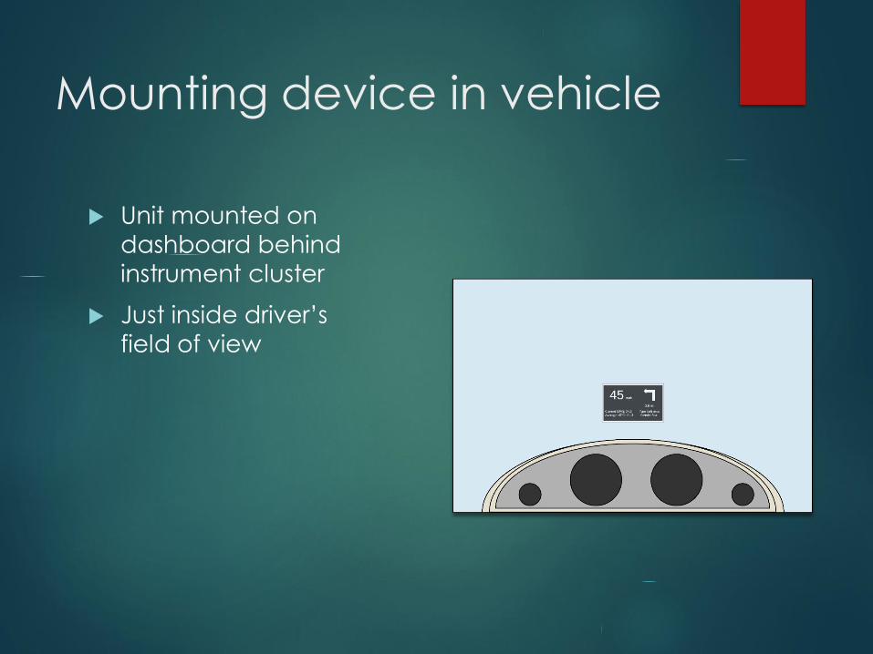
Mounting device in vehicle
Unit mounted on
dashboard behind
instrument cluster
Just inside driver’s
field of view

Microcontroller
ATmega 2560 8-bit Microcontroller
54 Digital I/O Pins, of which 15 Pins provide PWM
Output
16 Analog Input Pins
5V Operating Voltage
256KB Flash Memory
16 MHz Clock Speed
Popular for embedded projects such as robotics
Read in and process data for subsystems of Huddy
Buddy

Crash Detection System
Microcontroller uses accelerometer to detect large change in forces
Read in values for gravity relative to x, y, and z axes
If a large change in values is detected, microcontroller will initiate emergency response sequence
Microcontroller issues commands to Cellular 2G Module
Retrieve current GPS Coordinates
Send text message containing coordinates to emergency contact
In event of power loss, backup power takes over
Power generation switch on impact

Crash Detection System
Huddy
Buddy
Requests
GPS
Data
from
Satellite
Satellite
Returns
GPS
Data to
Huddy
Buddy
Huddy Buddy
sends SMS
containing
GPS
Coordinates
SMS travels
through
Cellular
Network to
Destination
SMS Delivered
to Emergency
Contact

Cellular and GPS Module
SIMCom SIM808 GSM 2G Cellular Module
Quad-Band GSM/GPRS Module with GPS for satellite
navigation
US Cellular Service via standard SIM Card
Ting Mobile
AT Command Implementation
Receives commands via UART Communication
External GSM/GPS Antennas
Supply Voltage: 3.4~4.4V

Accelerometer
Analog Devices ADXL335 3-Axis Accelerometer
± 3g sensitivity
Operating voltage: 1.8V - 3.6V
Analog pinouts for x,y,z axes
10,000 g shock survival

HUD Overview

Power Delivery
The power supply will be through the OBD-II port
that are in almost all cars today.
This will supply a steady 5 volt input and can deliver
up to 2.1 amps.
Another reason for this choice is because it is
possible to pull additional data from the car's
sensors and display them.

Power Delivery
Most of the components will be driven off of the 5
volt input but for a few of the peripheral parts,
they require either more or less voltage and to do
that either a buck or boost converter.
The LM2577-ADJ will be used for the LED backlight
which will supply 9 volts and up to 800 mA if
needed.
The LM317 will supply 3.3 volts for the ADXL335
accelerometer sensor.

Light Sensor
Light is
Like
Lux Value Approxiamte
Photoresistor
Value
Current
(mA)
Voltage
(V)
Moonlight 1 70 kΩ 0.0704 0.07
Dark
Room
10 10 kΩ 0.455 0.455
Bright
Room
100 1.5 kΩ 2 2
Overcast
Day
1000 300 Ω 3.85 3.85
Daylight 10000 100 Ω 4.55 4.55
Response of Photodiode used with a 1 kΩ resistor

LED Backlight Dimmer
The LED backlight is super bright and to not
constantly blind the driver a dimmer circuit is to
be used in conjunction with the photodiode.
The photodiode's analog input will be translated
into duty cycles for the PWM on the ATMEGA2560.
If it's dark and needs to be brighter a shorter duty
cycle will be needed. If it's bright and less light is
needed then a larger duty cycle will be needed.

LED Backlight Dimmer

Backup Battery System
In the event of a crash and no power can be
provided to the SMS module, there still needs to
be power to allow for the emergency text
message or email to be sent out to the respective
emergency contacts.
The normal DC power supply will be connected to
a blocking diode rated at a current higher than the
power supply. Then the rechargeable battery is
connected to the circuit with a resistor and another
diode. The value of the resistor is very important
because while the battery isn’t being used its going
to be charged.

Backup Battery System

PCB Development
Being a beginner with designing PCBs there are a
lot of designer tools out there and the one I went
with is called DipTrace. It is very easy to use and
in my opinion is a lot like Mulitsim which most
everyone is familiar with.
One small drawback is having to make individual
part schmatics and footprints, but there are tools to
easily make the parts that were not included in its
already extensive library.
The supplier for most of the RLC components can
be obtained through Mouser.com. The actual chips
may come from separate vendors. The PCB will be
created through JLCPCB.

PCB Development
(ATmega2560)

PCB Development
(nRF52840)

PCB Development
(SIM808)

PCB Development
(ADXL335)

HUD Overview

App
Development
Android Studio using Java
Mapbox for API calls and data
Choose location to route to
based on current location of
device
Allows checking of Bluetooth
connection status
Designate Emergency Contact

Bluetooth
❖ Nordic nRF52840
❖ 2.4 GHz Transceiver
❖ 2 Mbps, 1 Mbps, Long
Range
❖ Supports Bluetooth
Low Energy. Low
latency
❖ Extensive
documentation
including schematics
and SDK information
❖ Firmware written in C

Work Distribution
name Optics and
Display
PCB and
Power
Delivery
HUD
Programming
App
Development
Aaron ✓
Evan ✓
Logan ✓
Pedrhom ✓

Financing
Exclusively Student Funded
Logging all items purchased
Splitting overall cost at end of project
Use of tools provided by the University of Central
Florida
TI Innovation Lab
Senior Design Lab

Item Description Price ($)
PCB Implement all hardware needed onto PCB 40
Display Unit Display information to driver on windshield 100
Power Delivery
System
Provides power to system ~45
Microprocessor Processes data and sends to display 50
LEDs Show power states and pertinent information 15
Soldering Equipment Needed to implement electrical components Provided by UCF
Bluetooth Module Receive data from phone over Bluetooth
connection
20
Bluetooth Testing
Development Board
Allows debugging and initial exposure to the
nRF52840 through Arduino and Nordic SDK
25
J-Link OB ARM
Programmer
Flashes firmware and sends code to blank
Bluetooth Module
5
Oscilloscope Allows testing of RF portions and voltage
differencesProvided by UCF
Speaker Play recorded sounds in specific situations ~10
Mobile Smartphone Needed to host custom Application N/A
GPS/Cellular Module Feed location data to system and send SMS
messages
90
Battery Used as backup power source 20
OBDII Connector Needed to get data from vehicle’s OBDII Port 45
Financing

Project Completion Status
0 10 20 30 40 50 60 70 80 90 100
Enclosure Design Development
App Development
Component Software Development
PCB Schematic Design
Initial Parts Acquisition and Testing
Percent Complete
To Be Started: Firmware Development, Bare Element
Acquisition, PCB Acquisition and Testing

Challenges
Writing firmware for hardware components
Selecting display components that will physically
fit into our specified size
Ensuring compatibility with a wide variety of
vehicles and smartphones
Unexpected issues with components
Durability of SIM5320 3G GSM Module
Configuration of SIM808 Module
Software Debugging

Plans for Successful Design
Order PCB as soon as possible
Test remaining components to ensure proper
operation
Begin integrating individual components into
whole design
Work within scheduled timeline
Unexpected issues
Stay within relative scope

Works Cited
Figure 1. OBD-II picture. Retrieved
from https://www.digikey.com/product-
detail/en/sparkfun-electronics/CAB-10087/1568-
1227-
ND/5721422?utm_adgroup=Between%20Series%2
0Adapter%20Cables&utm_source=google&utm_
medium=cpc&utm_campaign=Shopping_Cable
%20Assemblies_NEW&utm_term=&utm_content=B
etween%20Series%20Adapter%20Cables&gclid=C
j0KCQiApaXxBRDNARIsAGFdaB_TN8czxIoyzaVaEY
N6X-
3ChxJNiaZz2ZLFHx6AWiBSORBKhtWuNI8aAu6kEAL
w_wcB. Accessed 23 Jan. 2020