hub-floating-point for improving fpga implementations of
TRANSCRIPT

1
HUB-Floating-Point for improving FPGAimplementations of DSP Applications
Javier Hormigo, and Julio Villalba, Member, IEEE
Abstract—The increasing complexity of new digital signal-processing applications is forcing the use of floating-point num-bers in their hardware implementations. In this brief, we inves-tigate the advantages of using HUB formats to implement thesefloating-point applications on FPGAs. These new floating-pointformats allow for the effective elimination of the rounding logic onfloating-point arithmetic units. Firstly, we experimentally showthat HUB and standard formats provide equivalent SNR on DSPapplication implementations. We then present a detailed studyof the improvement achieved when implementing floating-pointadders and multipliers on FPGAs by using HUB numbers. Inmost of the cases studied, the HUB approach reduces resource useand increases the speed of these FP units, while always providingstatistically equivalent accuracy as that of conventional formats.However, for some specific sizes, HUB multipliers require farmore resources than the corresponding conventional approach.
Index Terms—FPGA, floating-point, DSP applications, HUB-format
I. INTRODUCTION
NOWADAYS, many Digital Signal Processing (DSP) ap-plications, such as graphics, wireless communications,
industrial control, and medical imaging require the use of lin-ear algebra or other complex algorithms. The use of Floating-Point (FP) arithmetic is quickly becoming a requirement inthese applications due to its extended dynamic range andprecision. For this reason, FP arithmetic is being introducedon FPGA implementations, as a soft-core [1] [2], or even asa hardware block in the newest Altera devices [3]. Althoughthese embedded hardware blocks are more efficient and costeffective than their equivalent soft-core designs, the latter arestill very useful. Firstly, low-cost devices do not offer these FPembedded blocks and it is not clear that other FPGA brandsare going to include something similar in their devices inthe near future. Secondly, up to now, only single precisionhas been directly supported in DSP blocks [4]. Therefore,improvements to the soft-core implementations are of greatvalue.
Some of these solutions are being designed to followthe IEEE754 standard [5]. However, in many applications,compliance with this standard is sacrificed to obtain moreefficient implementations regarding area and performance. Inrelation to FPGAs, much more efficient designs are obtainedby using more flexible implementations of FP numbers andensuring the fulfillment of certain quality parameters at the
This work was supported in part by the Ministry of Education and Scienceof Spain under contracts TIN2013-42253-P.
The authors are with the Department of Computer Architecture, Uni-versidad de Malaga, Malaga E-29071 Spain (e-mail: [email protected];[email protected]).
output. These flexible implementations could utilize word-length optimization [6] [7], high-radix representation [8], andfused datapath synthesis [9], or avoid the implementation ofunnecessary rounding modes [2], exceptions, or subnormalssupport [1].
Generally, both hard and soft cores only support the round-to-nearest-even (RNE) mode, since this is the most useful ofthe rounding modes. In these FP cores, a significant amount ofresource use and delay is due to the rounding logic. However,two new families of formats, HUB (Half-Unit biased) [10]and Round-to-Nearest [11] representations, allow RNE to beperformed simply by truncation, which could make roundinglogic negligible. Here, we focus on HUB formats. HUBFixed-point formats were used in [12] and [13] to improveDSP implementations, since they allow better word-lengthoptimization. The ASIC implementation of HUB-FP unitshas been studied for binary16 (half), binary32 (single), andbinary64 (double) [5], and important improvements have beenachieved [14] [15]. In this brief communication, we extendthis analysis to FPGAs over a wide range of sizes. Comparedto previous articles, we provide:• An experimental error analysis of the implementation of
FIR filters, which shows that the HUB approach providessimilar statistical parameters to those of standard FPimplementations, including the SNR.
• The results of FPGA implementation of a basic FP adderand multiplier for a wide range of exponent and mantissabit-widths under HUB and conventional approaches andtheir comparison.
In most of the cases studied, the HUB format reducesresource use and increases the speed of these FP units.Furthermore, due to its simplicity, any existing soft or hardcore could be easily enhanced by using the proposed approach.Therefore, based on basic architectures, our aim is to encour-age researchers to improve their optimized FP cores or DSPapplications by using HUB-FP formats.
II. HUB-FP NUMBERS AND ASSOCIATED CIRCUITS
Firstly, we summarize the main characteristics of the HUB-FP formats and circuits presented in [10] [15]. For demonstra-tions or further explanations, please refer to these papers.
A HUB-FP number is an FP number such that its mantissa(or significand) has an Implicit Least Significant Bit (ILSB)which equals one. Compared with a standard format, it hasthe same number of explicit bits and precision, but the samebit-vector represents a value biased half Unit-in-the-Last-Place (ulp) [10]. For example, using an m-bit HUB number

2
1 1Mx My
Pre−conditioning
Operation
Normalization
Rounding
Sticky bit
Ex Ey
Ez Mz
Exp. Comp.
Exp. Update
Fig. 1. Basic HUB-FP arithmetic architecture
normalized between (1, 2) for the mantissa (Mx), a sign bit(Sx), and an exponent Ex, the HUB-FP X’= (Sx, Ex,Mx)
′
represents
(Sx, Ex,Mx)′ = (−1)Sx ·
([0∑
i=−m+1
Xi · 2i]+ 2−m
)· 2Ex
(1)where Xi are the m bits of the mantissa Mx. Now, let usconsider m = 4: the mantissa 1.001 represents 1.125 underconventional format, but 1.1875 under the HUB format, bothwith an error bound of ±0.0625. Therefore, an exact real valueis represented for different numbers under each approach, anda different rounding error is also produced, but both errors arewithin the ±0.5ulp bound.
The main advantages of using the HUB format are thattwo’s complement is computed by only bit-wise inversion, thetruncation of a value to obtain a HUB number produces anequivalent RNE, and a sticky-bit computation is not requiredfor most operations. Moreover, the conversion to a conven-tional format only requires explicitly appending the ILSB tothe original number. Therefore, HUB numbers could be easilyoperated by conventional arithmetic circuits, while practicallyeliminating the rounding logic. Furthermore, the impact of theinclusion of the ILSB is limited since it is constant.
A basic general architecture to operate HUB-FP numbers isshown in Fig. 1, where a conventional FP arithmetic unit hasbeen conveniently modified. Firstly, the ILSBs are appendedto the mantissas of the input operands before using them.As consequence they are converted to conventional format.Next, a conventional datapath is used, but at first the mantissadata-path has to be one-bit wider. Since the final result is inHUB format, a simple truncation is performed for rounding.Thus, after the arithmetic operation itself, a conventionalnormalization logic is utilized, but no guard bit is provided atthe output. The rounding logic of the conventional architectureis simply eliminated (crossed out in Fig. 1).
Taking into account that the ILSB is a constant, this generalarchitecture could be further optimized depending on thespecific architecture. A detailed architecture for addition andmultiplication is provided in [15].
0 100 200 300 400 500 600 700
−4
−2
0
2
4
6x 10
−7
Err
or
Samples
HUB .IEEE .
Fig. 2. Absolute error of the output of 150-tap FIR filter when using singleinstead of double precision
TABLE ISTATISTICAL PARAMETERS OF THE ROUNDING ERROR DISTRIBUTION.
IEEE HUB IEEE HUB IEEE HUB IEEE HUB
Taps min(10−7 ) mean(10−9 ) max(10−7 ) σ(10−8 )
FIR100 -5.25 -5.17 0.036 -0.32 4.83 4.39 0.86 0.87FIR125 -5.32 -4.98 -1.84 -1.61 6.02 5.30 1.02 1.00FIR150 -5.51 -6.11 -0.54 -1.90 5.88 5.88 1.05 1.04FIR175 -7.47 -7.35 1.33 0.38 5.31 6.10 1.20 1.18FIR200 -7.95 -8.08 -2.01 -1.55 7.17 7.03 1.22 1.20
III. ROUNDING ERROR OF HUB-FP COMPUTATION
The equivalence between truncation under HUB formatsand RNE under conventional formats has been theoreticallydemonstrated in [10] and experimentally demonstrated for iso-lated operations in [15]. In this section, we show that althoughthe specific error for each output value is always different,the statistical error performance of the HUB approach is verysimilar to the conventional one for DSP applications.
Specifically, several FIR filters have been implementedusing IEEE double-precision as reference designs. Similarly,the output of the same filters was computed using single-precision for both the IEEE-754 standard and the correspond-ing HUB format. Conventional computation was performedusing MATLAB in a PC, whereas the results of the HUBapproach were obtained through VHDL simulation. Next,we analyze the error observed between double- and single-precision implementations.
As an example, Fig. 2 shows the absolute error of the outputsamples for both approaches, corresponding to a 150-tap low-pass FIR filter when a chirp signal is introduced. As expected,the error corresponding to conventional and HUB approachesis always different. Since the exactly-represented numbersof both approaches are different, the rounding error cannotcoincide. However, they are distributed in the practically sameway. To measure this outcome, similar experiments wereperformed for several low-pass filters, using a chirp inputsignal with 10000 samples. Table I shows some statisticalparameters of the error for these experiments, including the
3
0 100 200 300 400 500 600 700−1
−0.5
0
0.5
1Input signal
0 100 200 300 400 500 600 700−1
−0.5
0
0.5
1Output signal
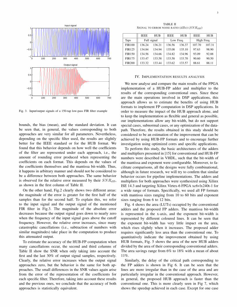
Fig. 3. Input/output signals of a 150-tap low-pass FIR filter example
bounds, the bias (mean), and the standard deviation. It canbe seen that, in general, the values corresponding to bothapproaches are very similar for all parameters. Nevertheless,depending on the specific filter used, the results are slightlybetter for the IEEE standard or for the HUB format. Wefound that this behavior depends on how well the coefficientsof the filter are represented under each approach, i.e., theamount of rounding error produced when representing thecoefficients on each format. This depends on the values ofthe coefficients themselves and the mantissa bit-width. Thus,it happens in arbitrary manner and should not be considered tobe a difference between both approaches. The same behavioris observed for the relative error measured by their SNRdB ,as shown in the first column of Table II.
On the other hand, Fig.2 clearly shows two different areas:the magnitude of the error is greater for the first half of thesamples than for the second half. To explain this, we referto the input signal and the output signal of the mentionedFIR filter in Fig.3. The magnitude of the absolute errordecreases because the output signal goes down to nearly zerowhen the frequency of the input signal goes above the cutofffrequency. However, the relative error increases, since manycatastrophic cancellations (i.e., subtraction of numbers withsimilar magnitudes) take place in the computation to producethis attenuated output.
To estimate the accuracy of the HUB-FP computation whenmany cancellations occur, the second and third columns ofTable II show the SNR when only taking into account thefirst and the last 30% of output signal samples, respectively.Clearly, the relative error increases when the output signalapproaches zero, but the behavior is the same for both ap-proaches. The small differences in the SNR values again arisefrom the error of the representation of the coefficients foreach specific filter. Therefore, taking into account these resultsand the previous ones, we conclude that the accuracy of bothapproaches is statistically equivalent.
TABLE IISIGNAL TO ERROR NOISE RATIO (dBs) (SNRdB )
IEEE HUB IEEE HUB IEEE HUB
Taps Full signal Low Freq. High Freq.
FIR100 136.24 136.21 136.56 136.37 107.70 107.31FIR125 134.84 134.94 135.08 135.10 97.63 98.90FIR150 134.56 134.66 134.82 134.96 93.09 92.88FIR175 133.47 133.58 133.58 133.70 90.60 90.50FIR200 133.32 133.44 133.62 133.57 88.61 88.11
IV. IMPLEMENTATION RESULTS ANALYSIS
We now analyse and compare the main results of the FPGAimplementation of a HUB-FP adder and multiplier to theresults of the corresponding conventional ones. Since theseare the main operations involved in DSP applications, thisapproach allows us to estimate the benefits of using HUBformats to implement FP computation in DSP applications. Inorder to measure the impact of the HUB approach alone, andto keep the implementation as flexible and general as possible,our implementations allow any bit-width, but do not supportspecial cases, subnormal cases, or any optimization of the data-path. Therefore, the results obtained in this study should beconsidered to be an estimation of the improvement that can beachieved by using HUB-FP formats and to encourage furtherinvestigation using optimized cores and specific applications.
To perform this study, the basic architectures of the addersand multipliers presented in [15] for conventional and HUB-FPnumbers were described in VHDL, such that the bit-width ofthe mantissa and exponent were configurable. Moreover, to fa-cilitate comparisons, all the designs were fully combinational,although in future research, we will try to confirm that similarbehavior occurs for pipeline implementations. The adders andmultipliers for both approaches were synthesized using XilinxISE 14.3 and targeting Xilinx Virtex-6 FPGA xc6vlx240t-1 fora wide range of formats. Specifically, we used all FP formatswith mantissa sizes ranging from 10 to 60 bits and exponentsizes ranging from 6 to 12 bits.
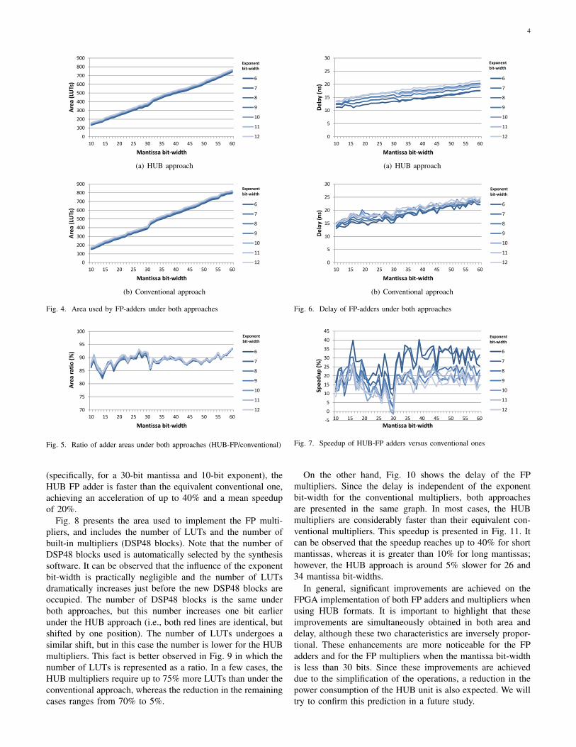
Fig. 4 shows the area (LUTs) occupied by the conventionaladders and the proposed FP adders. The mantissa bit-widthis represented in the x-axis, and the exponent bit-width isrepresented by different coloured lines. It can be seen thatthe exponent bit-width has very little impact on the area,which rises slightly when it increases. The proposed adderrequires significantly less area than the conventional one. Toquantitatively indicate the improvement obtained by usingHUB formats, Fig. 5 shows the area of the new HUB addersdivided by the area of their corresponding conventional adders.The area savings range from 6% to 18% with a mean of about11%.
Similarly, the delay of the critical path corresponding tothe FP adders is shown in Fig 6. It can be seen that thelines are more irregular than in the case of the area and areparticularly irregular in the conventional approach. However,in general, the proposed HUB approach is faster than theconventional one. This is more clearly seen in Fig 7, whichshows the speedup achieved in each case. Except for one case
4
0
100
200
300
400
500
600
700
800
900
10 15 20 25 30 35 40 45 50 55 60
Area
(LUTs)
Mantissa bit‐width
6
7
8
9
10
11
12
Exponentbit-width
(a) HUB approach
0
100
200
300
400
500
600
700
800
900
10 15 20 25 30 35 40 45 50 55 60
Area
(LUTs)
Mantissa bit‐width
6
7
8
9
10
11
12
Exponentbit-width
(b) Conventional approach
Fig. 4. Area used by FP-adders under both approaches
70
75
80
85
90
95
100
10 15 20 25 30 35 40 45 50 55 60
Area
ratio
(%)
Mantissa bit‐width
6
7
8
9
10
11
12
Exponentbit-width
Fig. 5. Ratio of adder areas under both approaches (HUB-FP/conventional)
(specifically, for a 30-bit mantissa and 10-bit exponent), theHUB FP adder is faster than the equivalent conventional one,achieving an acceleration of up to 40% and a mean speedupof 20%.
Fig. 8 presents the area used to implement the FP multi-pliers, and includes the number of LUTs and the number ofbuilt-in multipliers (DSP48 blocks). Note that the number ofDSP48 blocks used is automatically selected by the synthesissoftware. It can be observed that the influence of the exponentbit-width is practically negligible and the number of LUTsdramatically increases just before the new DSP48 blocks areoccupied. The number of DSP48 blocks is the same underboth approaches, but this number increases one bit earlierunder the HUB approach (i.e., both red lines are identical, butshifted by one position). The number of LUTs undergoes asimilar shift, but in this case the number is lower for the HUBmultipliers. This fact is better observed in Fig. 9 in which thenumber of LUTs is represented as a ratio. In a few cases, theHUB multipliers require up to 75% more LUTs than under theconventional approach, whereas the reduction in the remainingcases ranges from 70% to 5%.
0
5
10
15
20
25
30
10 15 20 25 30 35 40 45 50 55 60
Delay (ns)
Mantissa bit‐width
6
7
8
9
10
11
12
Exponentbit-width
(a) HUB approach
0
5
10
15
20
25
30
10 15 20 25 30 35 40 45 50 55 60
Delay (ns)
Mantissa bit‐width
6
7
8
9
10
11
12
Exponentbit-width
(b) Conventional approach
Fig. 6. Delay of FP-adders under both approaches
‐5
0
5
10
15
20
25
30
35
40
45
10 15 20 25 30 35 40 45 50 55 60
Spee
dup (%
)
Mantissa bit‐width
6
7
8
9
10
11
12
Exponentbit-width
Fig. 7. Speedup of HUB-FP adders versus conventional ones
On the other hand, Fig. 10 shows the delay of the FPmultipliers. Since the delay is independent of the exponentbit-width for the conventional multipliers, both approachesare presented in the same graph. In most cases, the HUBmultipliers are considerably faster than their equivalent con-ventional multipliers. This speedup is presented in Fig. 11. Itcan be observed that the speedup reaches up to 40% for shortmantissas, whereas it is greater than 10% for long mantissas;however, the HUB approach is around 5% slower for 26 and34 mantissa bit-widths.
In general, significant improvements are achieved on theFPGA implementation of both FP adders and multipliers whenusing HUB formats. It is important to highlight that theseimprovements are simultaneously obtained in both area anddelay, although these two characteristics are inversely propor-tional. These enhancements are more noticeable for the FPadders and for the FP multipliers when the mantissa bit-widthis less than 30 bits. Since these improvements are achieveddue to the simplification of the operations, a reduction in thepower consumption of the HUB unit is also expected. We willtry to confirm this prediction in a future study.

5
0
2
4
6
8
10
12
14
16
0
50
100
150
200
250
300
350
10 15 20 25 30 35 40 45 50 55 60
Num
ber o
f DSP48
s
Area
(LUTs)
Mantissa bit‐width
6
7
8
9
10
11
12
DSP48s
Exponentbit-width
(a) HUB approach
0
2
4
6
8
10
12
14
16
0
50
100
150
200
250
300
350
10 15 20 25 30 35 40 45 50 55 60
Num
ber D
SP48
s
Area
(LUTs)
Mantissa bit‐width
6
7
8
9
10
11
12
DSP48s
Exponentbit-width
(b) Conventional approach
Fig. 8. Area used by FP-multipliers under both approaches
020406080100120140160180200
10 15 20 25 30 35 40 45 50 55 60
Area
ratio
(%)
Mantissa bit‐width
6
7
8
9
10
11
12
Exponentbit-width
Fig. 9. Ratio of multiplier areas under both approaches (HUB-FP/conventional)
V. CONCLUSIONS
In this brief, we investigated the use of HUB-FP formats toenhance the implementation of DSP applications on FPGA.Firstly, the statistical equivalence of the accuracy of HUBand standard FP computations was empirically verified by theimplementation of FIR filters. It was shown that although thevalues of the results are different, the SNR of both approacheswas practically the same. The advantages of implementingHUB-FP arithmetic units on FPGA instead of standard oneswere measured for addition and multiplication, which are thekey operations on most DSP applications. The elimination ofthe rounding logic can significantly reduce both area and delay.We studied this improvement for a wide range of mantissaand exponent bit-widths and showed that that HUB units wereclearly superior in most of the cases analyzed. Furthermore,due to the nature of the improvement, most current soft orhard cores could be easily enhanced by using the proposedapproach. We should also note that several patent applicationshave been filed regarding several HUB circuits.
0
2
4
6
8
10
12
14
16
10 15 20 25 30 35 40 45 50 55 60
Delay (ns)
Mantissa bit‐width
conv.
6
7
8
9
10
11
12
Exponentbit-width
Fig. 10. Delay of FP-multiplier under both approaches
‐10
0
10
20
30
40
50
10 15 20 25 30 35 40 45 50 55 60
Spee
dup
(%)
Mantissa bit‐width
6
7
8
9
10
11
12
Exponent bit-width
Fig. 11. Speedup of HUB-FP multipliers versus conventional ones
REFERENCES
[1] F. de Dinechin and B. Pasca, “Designing custom arithmetic data pathswith FloPoCo,” Design Test of Computers, IEEE, vol. 28, no. 4, pp.18–27, July 2011.
[2] Xilinx, “LogiCORE IP floating-point operator v7.0, product guide,PG060,” www.xilinx.com/support/documentation, 2014.
[3] Altera, “Arria10 device overview,” https://www.altera.com, 2015.[4] M. Langhammer and B. Pasca, “Design and implementation of an
embedded FPGA floating point DSP block,” in Computer Arithmetic(ARITH), 2015 IEEE 22nd Symposium on, June 2015, pp. 26–33.
[5] IEEE Task P754, IEEE 754-2008, Standard for Floating-Point Arith-metic, Aug. 2008.
[6] A. Gaffar, O. Mencer, and W. Luk, “Unifying Bit-Width Optimisationfor Fixed-Point and Floating-Point Designs,” in IEEE Symp. on Field-Programmable Custom Computing Machines, 2004, pp. 79–88.
[7] D. Boland and G. Constantinides, “A scalable precision analysis frame-work,” Multimedia, IEEE Trans., vol. 15, no. 2, pp. 242–256, Feb 2013.
[8] A. Ehliar, “Area efficient floating-point adder and multiplier with IEEE-754 compatible semantics,” in Field-Programmable Technology (FPT),2014 International Conference on, Dec 2014, pp. 131–138.
[9] M. Langhammer, “Floating point datapath synthesis for FPGAs,” inField Programmable Logic and Applications, 2008. FPL 2008. Inter-national Conference on, Sept 2008, pp. 355–360.
[10] J. Hormigo and J. Villalba, “New formats for computing with real-numbers under round-to-nearest,” Computers, IEEE Transactions on,vol. PP, no. 99, pp. –, 2015, early access.
[11] P. Kornerup, J.-M. Muller, and A. Panhaleux, “Performing arithmeticoperations on round-to-nearest representations,” Computers, IEEE Trans.on, vol. 60, no. 2, pp. 282–291, Feb 2011.
[12] J. Hormigo and J. Villalba, “Optimizing DSP circuits by a new familyof arithmetic operators,” in Signals, Systems and Computers, AsilomarConference on, Nov 2014, pp. 871–875.
[13] S. D. Munoz and J. Hormigo, “Improving fixed-point implementationof QR decomposition by rounding-to-nearest,” in Consumer Electronics(ISCE 2015), 19th IEEE Int. Symp. on, June 2015, pp. 1–2.
[14] J. Hormigo and J. Villalba, “Simplified floating-point units for highdynamic range image and video systems,” in Consumer Electronics(ISCE 2015), 19th IEEE Int. Symp. on, June 2015, pp. 1–2.
[15] ——, “Measuring improvement when using HUB formats to implementfloating-point systems under round-to-nearest,” Very Large Scale Inte-gration (VLSI) Systems, IEEE Transactions on, vol. PP, no. 99, pp. 1–9,2015, early access.