huaei sfpgsmm copatile aa copliant ases sfp ransceier mmf
TRANSCRIPT
Features:
Applications:
Product Description
ProLabs’s transceivers are RoHS compliant and lead-free.
TAA refers to the Trade Agreements Act (19 U.S.C. & 2501-2581), which is intended to foster fair and open international trade. TAA requires that the U.S. Government may acquire only “U.S. – made or designated country end products.”
SFP-GE-SX-MM850-A-CHuawei® SFP-GE-SX-MM850 Compatible TAA Compliant 1000Base-SX SFP Transceiver (MMF, 850nm, 550m, LC)
• INF-8074 and SFF-8472 Compliance • Duplex LC Connector • VCSEL transmitter and PIN receiver • Multi-mode Fiber • Commercial Temperature 0 to 70 Celsius • Hot Pluggable • Metal with Lower EMI • Excellent ESD Protection • RoHS Compliant and Lead Free
• 1000Base-SX Ethernet • 1x Fibre Channel • Access and Enterprise
This Huawei® SFP-GE-SX-MM850 compatible SFP transceiver provides 1000Base-SX throughput up to 550m over multi-mode fiber (MMF) using a wavelength of 850nm via an LC connector. It is guaranteed to be 100% compatible with the equivalent Huawei® transceiver. This easy to install, hot swappable transceiver has been programmed, uniquely serialized and data-traffic and application tested to ensure that it will initialize and perform identically. It is built to meet or exceed the specifications of Huawei®, as well as to comply with MSA (Multi-Source Agreement) standards to ensure seamless network integration. This transceiver is Trade Agreements Act (TAA) compliant. We stand behind the quality of our products and proudly offer a limited lifetime warranty.
Rev. 010322

Regulatory Compliance • ESD to the Electrical PINs: compatible with MIL-STD-883 Method 3015. • ESD to the Duplex LC Receptacle: compatible with IEC 61000-4-2. • Immunity compatible with IEC 61000-4-3. • EMI compatible with FCC Part 15 Class B EN55022 Class B (CISPR 22B) VCCI Class B. • Laser Eye Safety compatible with FDA 21CFR 1040.10 and 1040.11 EN60950, EN (IEC) 60825-1,2. • RoHs compliant with 2002/95/EC 4.1&4.2 2005/747/EC.
Absolute Maximum Ratings Parameter Symbol Min. Max. Unit
Supply Voltage Vcc -0.5 4.0 V
Storage Temperature TS -40 85 °C
Operating Humidity RH 5 95 %
Electrical Characteristics (TOP=25°C, Vcc=3.3V) Parameter Symbol Min. Typ. Max. Unit Notes
Transmitter
Input differential impedance Rin 100 Ω 1
Single ended data input swing Vin, pp 250 1200 mV
TX Disable-High Vcc-1.3 Vcc V
TX Disable-Low Vee Vee+0.8 V
TX Fault-High Vcc-0.5 Vcc V
TX Fault-Low Vee Vee+0.5 V
Receiver
Single ended data output swing Vout, pp 300 400 800 mV 2
Data output rise time tr 175 ps 3
Data output fall time tf 175 ps 3
LOS-High Vcc-0.5 Vcc V
LOS-Low Vee Vee+0.5 V
Notes: 1. AC coupled. 2. Into 100 ohm differential termination. 3. 20% - 80%

Optical and Electrical Characteristics Parameter Symbol Min. Typ. Max. Unit Notes
Transmitter
Average Output Power PO -9 -4 dBm 1
Optical Wavelength λ 830 850 860 nm
Spectral Width σ 0.85 nm
Optical Rise/Fall Time tr/tf 260 ps 2
Total Jitter TJ 200 ps
Optical Extinction Ratio ER 9 dB
Receiver
Receiver Sensitivity RSENS -18 dBm 3,4
Maximum Received Power RXMAX 0 dBm
Centre Wavelength λC 770 860 nm
LOS De-Assert LOSD -26 dBm
LOS Assert LOSA -40 dBm
LOS Hysteresis 0.5 5 dB
Notes:
1. Class 1 Laser Safety. 2. Unfiltered, 20%-80%. Complies with GE and 1x FC eye masks when filtered. 3. Measured with conformance signals defined in FC-PI-2 Rev. 10.0 specifications. 4. Measured with PRBS 27-1 at 10-10 BER.
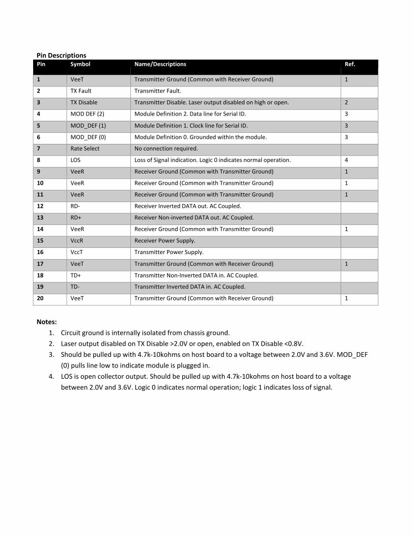
Pin Descriptions Pin Symbol Name/Descriptions Ref.
1 VeeT Transmitter Ground (Common with Receiver Ground) 1
2 TX Fault Transmitter Fault.
3 TX Disable Transmitter Disable. Laser output disabled on high or open. 2
4 MOD DEF (2) Module Definition 2. Data line for Serial ID. 3
5 MOD_DEF (1) Module Definition 1. Clock line for Serial ID. 3
6 MOD_DEF (0) Module Definition 0. Grounded within the module. 3
7 Rate Select No connection required.
8 LOS Loss of Signal indication. Logic 0 indicates normal operation. 4
9 VeeR Receiver Ground (Common with Transmitter Ground) 1
10 VeeR Receiver Ground (Common with Transmitter Ground) 1
11 VeeR Receiver Ground (Common with Transmitter Ground) 1
12 RD- Receiver Inverted DATA out. AC Coupled.
13 RD+ Receiver Non-inverted DATA out. AC Coupled.
14 VeeR Receiver Ground (Common with Transmitter Ground) 1
15 VccR Receiver Power Supply.
16 VccT Transmitter Power Supply.
17 VeeT Transmitter Ground (Common with Receiver Ground) 1
18 TD+ Transmitter Non-Inverted DATA in. AC Coupled.
19 TD- Transmitter Inverted DATA in. AC Coupled.
20 VeeT Transmitter Ground (Common with Receiver Ground) 1
Notes:
1. Circuit ground is internally isolated from chassis ground. 2. Laser output disabled on TX Disable >2.0V or open, enabled on TX Disable <0.8V. 3. Should be pulled up with 4.7k-10kohms on host board to a voltage between 2.0V and 3.6V. MOD_DEF
(0) pulls line low to indicate module is plugged in. 4. LOS is open collector output. Should be pulled up with 4.7k-10kohms on host board to a voltage
between 2.0V and 3.6V. Logic 0 indicates normal operation; logic 1 indicates loss of signal.

Pin-out of connector Block on Host board
Recommend Circuit Schematic

Recommended Operating Conditions Parameter Symbol Min. Typ. Max. Unit
Power Supply Voltage Vcc 3.13 3.30 3.47 V
Power Supply Current Icc 250 mA
Case Operating Temperature – Commercial
Tc 0 70 °C
Case Operating Temperature – Industrial
Ti -40 85 °C
Data Rate (Gigabit Ethernet) 1.25 Gbps
Data Rate (Fibre Channel) 1.063 Gbps
50/125µm MMF L 550 m
Mechanical Specifications Small Form Factor Pluggable (SFP) transceivers are compatible with the dimensions defined by the SFP Multi- Sourcing Agreement (MSA).

EEPROM Information EEPROM memory map specific data field description is as below:
Digital Diagnostic Monitoring Interface Five transceiver parameter values are monitored. The following table defines the monitored parameter's accuracy. Parameter Range Accuracy Calibration
Temperature 0°C to 70°C (C) ±3°C Internal
-40°C to 85°C (I)
Voltage 2.97V to 3.63V ±3% Internal
Bias Current 0mA to 100mA ±10% Internal
TX Power -9dBm to -4dBm ±3dB Internal
RX Power -18dBm to 0dBm ±3dB Internal

About ProLabsOur experience comes as standard; for over 15 years ProLabs has delivered optical connectivity solutions that give our customers freedom and choice through our ability to provide seamless interoperability. At the heart of our company is the ability to provide state-of-the-art optical transport and connectivity solutions that are compatible with over 90 optical switching and transport platforms.
Complete Portfolio of Network Solutions
ProLabs is focused on innovations in optical transport and connectivity. The combination of our knowledge of optics and networking equipment enables ProLabs to be your single source for optical transport and connectivity solutions from 100Mb to 400G while providing innovative solutions that increase network efficiency. We provide the optical connectivity expertise that is compatible with and enhances your switching and transport equipment.
Trusted Partner
Customer service is our number one value. ProLabs has invested in people, labs and manufacturing capacity to ensure that you get immediate answers to your questions and compatible product when needed. With Engineering and Manufacturing offices in the U.K. and U.S. augmented by field offices throughout the U.S., U.K. and Asia, ProLabs is able to be our customers best advocate 24 hours a day.
Contact Information ProLabs US
Email: [email protected] Telephone: 952-852-0252
ProLabs UK
Email: [email protected]: +44 1285 719 600