hts dipole magnet
TRANSCRIPT

NATIONAL RESEARCH CENTER «KURCHATOV INSTITUTE»
INSTITUTE FOR HIGH ENERGY PHYSICS
I.V. Bogdanov, S.S. Kozub, V.M. Smirnov, V.V. Sytnik, I.S. Terskiy, L.M. Tkachenko, O.V. Trusov, L.S. Shirshov,
V.I. Shuvalov, P.A. Shcherbakov, A.A. Molodyk1, S.R. Lee1, S.V. Samoilnekov1
HTS Dipole Magnet
Submitted to Superconductor Science and Technology
––––––––––––– 1SuperOx
IHEP 2016−6
Protvino 2016

UDK 539.1.074.3 М-24
Abstract Bogdanov I.V., Kozub S.S., Smirnov V.M. et al. HTS Dipole Magnet: IHEP Preprint 2016–6. – Protvino, 2016. – p. 19, figs. 17, tables 4, refs.: 18.
The design and test results of the dipole magnet with HTS coil, made of a second-generation HTS tape, which was produced by JSC - "SuperOx", are presented. The dipole magnet is designed on the central magnetic field of 1 T in the aperture of 40×80 mm2.at 77 K The characteristics of the HTS tape, an insulation coating and steels, used in this magnet, are presented. The test results of the magnet at temperatures of 77, 65 and 4.2 K are presented and a comparison of measured and calculated results is performed.
Аннотация Богданов И.В., Козуб С.С., Смирнов В.М. и др. ВТСП дипольный магнит: Препринт ИФВЭ 2016−6. − Протвино, 2016. – 19 с., 17 рис., 4 табл., библиогр.: 18. Представлены конструкция и результаты испытаний дипольного магнита с ВТСП об-моткой. изготовленной из ВТСП ленты второго поколения производства ЗАО «СуперОкс». Ди-польный магнит рассчитан на центральное магнитное поле 1 Тл в апертуре 40×80 мм2 при 77 К. Приведены характеристики ВТСП ленты, ее изоляционного покрытия и сталей, использован-ных в этом магните. Представлены результаты испытаний магнита при температурах 77, 65 и 4,2 К и проведено сравнение измеренных и расчетных результатов.
© National research center «Kurchatov institute» State research center of Russian Federation Institute for high energy physics, 2016

1
1. Introduction
In recent years, active research has been carried out on using second-generation high
temperature superconducting (2G HTS) wire in industrial and scientific devices. Magnets and
devices, based on 2G HTS wire [1-11] can operate in the temperature range, attained with af-
fordable liquid nitrogen or cryocoolers, that gives the considerable cost saving in comparison
with LTS magnets, besides magnets with HTS inserts can create higher magnetic fields. Mag-
netic fields of 27 T (32 T design) have been demonstrated with HTS inserts in a LTS magnet
[1], as well as 24.6 T in an all-HTS magnet [2]. Commercial HTS dipole magnet was devel-
oped, using 1G HTS wires [3]. Replacing the resistive magnets by the HTS magnets in accel-
erators provides a significant reduction in operating costs [4, 5]. One of the first dipole mag-
nets, made with 2G HTS wire, reaching about 2 T at 18 K, was reported by Nielsen et al. [6].
At present, a collaborative effort lead by CERN is ongoing on the development and test of
HTS dipole magnets as inserts into LTS magnets, in order to reach magnetic field, exceeding
20 T in accelerator magnets [5, 7]. This paper describes the design, fabrication and test results
of the 2G HTS dipole magnet in Russia IHEP.
2. Design of the HTS Dipole Magnet
Figure 1 shows the cross-section of the HTS dipole magnet, and Table1 lists its main
parameters.

2
Figure 1. Cross-section sketch of the HTS dipole magnet.
Table 1. Main design parameters of the HTS dipole magnet.
Parameter Value
Nominal magnetic field in aperture 1 T Operating current 100 A Number of coils 2 Number of layers in each coil 2 Number of turns in each coil 180 Total number of turns 360 2G HTS wire cross-section without insulation 0.1×12 mm2
2G HTS wire insulation thickness 40 µm Longitudinal magnet length 425 mm Longitudinal coil length 418 mm Coil straight section length 250 mm Longitudinal yoke length 250 mm Aperture dimensions 40×80 mm2 Magnet mass 103
2.1. Magnet Coils
There are two double racetrack coils, located symmetrically at the top and bottom of a
304L stainless steel coil spool. Each coil consists of two layers, made of single pieces of 2G
HTS wire and connected with 60 mm bridge solder joints. The typical solder joint resistance,
measured at 77 K in self-field on short wire pieces is 13 nΩ. The number of turns in a coil

3
layer is 90, or 180 in each double racetrack, therefore the total number of turns in the magnet
is 360. The double racetrack coil layers are insulated with a 0.5 mm thick G11 glass-cloth-
base laminate. The coils are insulated from the yoke and the spool with a 2 mm thick G11
sheet.
2.2. Yoke
The iron yoke consists of four parts (Figure 1). Each part is made of 0.5 mm thick 2212
steel sheets with 5 µm varnish insulation. The yoke sheet stack is compressed between 8 mm
side plates with 10 mm 304L stainless steel rods and welded across the stack. The yoke fill
factor is 0.97. Four 304L stainless steel keys are used for the transverse alignment of the yoke
parts. The yoke parts are attached to the spool with bolts and then welded together.
3. Materials
3.1. 2G HTS Wire
The magnet coils were wound with the SuperOx 2G HTS wire (Table 2), based on the
non-magnetic Hastelloy C276 substrate. Ion beam assisted deposition (IBAD) was used for
buffer layer texturing and the GdBa2Cu3O7 HTS layer was grown by pulsed laser deposition
(PLD) [12]. The wire is finished with a 1.5 µm thick silver coating and a 20 µm thick sur-
round copper stabilising coating.
Table 2. Properties of the SuperOx 2G HTS wire used in the magnet coils.
Parameter Value Substrate Hastelloy C276 Minimum critical current (77 K, self-field) 400 A Width 12 mm Wire thickness without insulation 100 µm Silver coating 1.5 µm Copper coating 40 µm (20 µm per side)
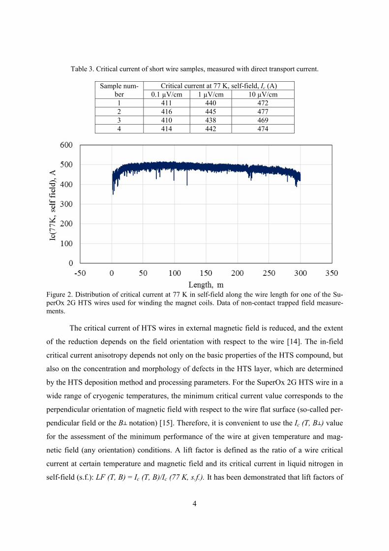
Figure 2 shows the distribution of critical current along the wire length for a typical
wire, measured by non-contact trapped field technique [13]. The non-contact measurements
were verified by direct transport current measurements of 50 mm long wire samples (Table
3), confirming critical currents above 400 A.
4
Table 3. Critical current of short wire samples, measured with direct transport current.
Sample num-ber
Critical current at 77 K, self-field, Ic (A) 0.1 µV/cm 1 µV/cm 10 µV/cm
1 411 440 472 2 416 445 477 3 410 438 469 4 414 442 474
Figure 2. Distribution of critical current at 77 K in self-field along the wire length for one of the Su-perOx 2G HTS wires used for winding the magnet coils. Data of non-contact trapped field measure-ments.
The critical current of HTS wires in external magnetic field is reduced, and the extent
of the reduction depends on the field orientation with respect to the wire [14]. The in-field
critical current anisotropy depends not only on the basic properties of the HTS compound, but
also on the concentration and morphology of defects in the HTS layer, which are determined
by the HTS deposition method and processing parameters. For the SuperOx 2G HTS wire in a
wide range of cryogenic temperatures, the minimum critical current value corresponds to the
perpendicular orientation of magnetic field with respect to the wire flat surface (so-called per-
pendicular field or the В notation) [15]. Therefore, it is convenient to use the Ic (Т, В) value
for the assessment of the minimum performance of the wire at given temperature and mag-
netic field (any orientation) conditions. A lift factor is defined as the ratio of a wire critical
current at certain temperature and magnetic field and its critical current in liquid nitrogen in
self-field (s.f.): LF (T, B) = Ic (T, B)/Ic (77 K, s.f.). It has been demonstrated that lift factors of

5
SuperOx 2G HTS wires reproduce well among wires from different production runs [15]. The
lift factors of SuperOx 2G HTS wires at various temperatures and magnetic field are shown in
Table 4 [16].
Table 4. Lift factors LF = Ic (Т,В)⁄Ic (77 K, s.f.) of SuperOx 2G HTS wire.
Magnetic field, B (T) Temperature, T (K) 5 20 40 65 77
0.0 11.1 8.40 5.13 2.30 1 0.5 8.25 5.10 2.53 0.82 0.30 1.0 6.06 3.60 1.78 0.55 0.18 1.5 4.93 2.89 1.43 0.42 0.12 2.0 4.22 2.45 1.21 0.33 0.08 2.5 3.78 2.17 1.07 0.28 0.06 3.0 3.41 1.95 0.96 0.23 0.04 3.5 3.11 1.79 0.88 0.20 0.03 4.0 2.88 1.67 0.80 0.17 0.02 4.5 2.67 1.55 0.74 0.15 0.02 5.0 2.52 1.45 0.69 0.13 0.01
3.2. Insulation of 2G HTS Wire
At IHEP, the 2G HTS wire was wrapped with 20 µm polyimide tape insulation at 50%
overlap; therefore, the resulting insulation thickness was 40 µm per side. An electric strength
of the insulation were measured on stacks of insulated 2G HTS wires (Figure 3) at room tem-
perature and under 10 MPa pressure, applied to the wide surface of the wire. The length of
measurement section was equal to 70 mm. A voltage was applied sequentially between all
neighbouring wires in a stack, pair by pair, thus, the turn-to-turn electric strength was meas-
ured between all wires in the stack. The pressure on the wire stack was applied using a hy-
draulic press. The insulation electrical resistivity was measured in the 50-2500 V operation
range.
6
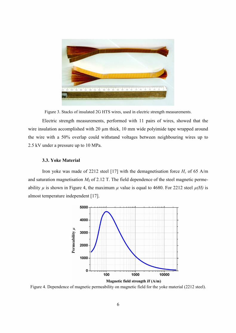
Figure 3. Stacks of insulated 2G HTS wires, used in electric strength measurements.
Electric strength measurements, performed with 11 pairs of wires, showed that the
wire insulation accomplished with 20 µm thick, 10 mm wide polyimide tape wrapped around
the wire with a 50% overlap could withstand voltages between neighbouring wires up to
2.5 kV under a pressure up to 10 MPa.
3.3. Yoke Material
Iron yoke was made of 2212 steel [17] with the demagnetisation force Hc of 65 A/m
and saturation magnetisation MS of 2.12 T. The field dependence of the steel magnetic perme-
ability µ is shown in Figure 4, the maximum µ value is equal to 4680. For 2212 steel µ(H) is
almost temperature independent [17].
Figure 4. Dependence of magnetic permeability on magnetic field for the yoke material (2212 steel).

7
3.4. Stainless Steel
Austenitic stainless steel 304L with low magnetic susceptibility was used in the dipole
magnet structure. At 77 K and 4.2 K, the magnetic susceptibility of 304L steel is below 0.01
[17].
4. Magnetic Properties of the Dipole Magnet
The MULTIC software [18] was used to model all magnetic properties of the dipole
magnet.
4.1. Effective Magnet Length
The effective length of the dipole magnet, Lef , was calculated, using the formula:
where B0(0,0,0) – magnetic field in the centre of the magnet and B0(0,0,z) – magnetic field
along the longitudinal axis of the magnet, with the origin in the centre of the magnet.
Figure 5 shows the dependence of the effective magnet length on the operating cur-
rent.
Figure 5. Calculated dependence of the effective magnet length on the operating current.

8
The effective magnet length at currents above 200 A increases because the yoke satu-
rates first in the central cross-section, therefore, the field in the centre grows more slowly with
increasing current.
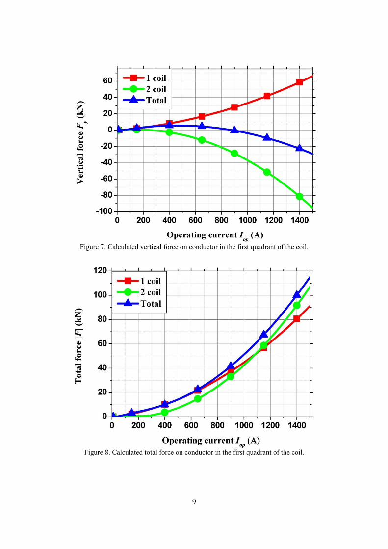
4.2. Magnetic Forces
The dependences of horizontal and vertical components of forces in the first quadrant
on operating current are shown in Figure 6-8 (“1 coil” and “2 coil” denote the coil layers
counting from the median plane; “Total” is the total force, applied at both layers in the first
quadrant).
Figure 6. Calculated horizontal force on conductor in the first quadrant of the coil.
9
Figure 7. Calculated vertical force on conductor in the first quadrant of the coil.
Figure 8. Calculated total force on conductor in the first quadrant of the coil.

10
4.3. Magnet Stored Energy and Inductance
The calculated inductance and stored energy of the magnet are shown in Figures 9 and
10. The inductance decreases with increasing operating current because the yoke saturates,
making the dependence of the central field on current non-linear.
Figure 9. Calculated dependence of the magnet inductance on operating current.
Figure 10. Calculated dependence of the magnet stored energy on operating current.

11
Figure 11 shows the assembled HTS dipole magnet.
Figure 11. Assembled 2G HTS dipole magnet.
5. Tests of HTS Dipole Magnet
5.1. Measurements Instrumentation
Figure 12 shows the schematic of the critical current measurement system, used for
testing the HTS dipole magnet.

12
Figure 12. Schematic of critical current measurement system.
A current to HTS coils was supplied, using Agilent 6680A power supply in current
stabilised mode, with voltage wave-function, controlled by Agilent 33200A function genera-
tor. Linear current ramp rate of 0.5 A/s was used.
The current through the coil was measured by Agilent 34420A digital voltmeter, using
a 300 A-75 mV shunt with a 0.5% accuracy. Another Agilent 34420A digital voltmeter was
used to measure voltage at the HTS coil.
Magnetic field was measured with a 1D Hall sensor, attached to a manipulation rod.
The Hall sensor voltage and the measurement shunt voltage were constantly logged during the
measurements.
5.2. Measurements in Liquid Nitrogen
The HTS dipole magnet was tested in liquid nitrogen at 77 and 65 K at 0.5 A/s current
ramp rate. The voltage-current (V-I) curve of the magnet is presented in Figure 13. The high
amplitude pulses on the V-I curve at low currents are due to the irregular current injection by
the power supply at the low circuit resistivity and the relatively high inductance. The slight
Function generator Agilent 33200A Power supply
Agilent 6680A
Digital voltmeter Agilent 34420A
Digital voltmeter Agilent 34420A
Shunt
HTS coil

13
voltage decrease at currents over 75 A was due to the yoke saturation and associated the mag-
net inductance decrease.
At 77 K the HTS coil current reached 110 and 113 A at 1 µV/cm and 10 µV/cm crite-
ria, respectively. At 113 A the central field was 1.12 T.
At 65 K the HTS coil current reached 226 and 228 A at 1 µV/cm and 10 µV/cm
criteria, respectively. At 228 A the central field was 1.66 T.
Figure 13. Measured current-voltage (V-I) curves of the HTS dipole magnet at 77 and 65 K.
Figure 14 shows the measured and calculated dependences of the magnet central field
on the operating current along with the field dependences of the 2G HTS wire critical current
at 77 and 65 K (for Ic (77 K, s.f.) = 400 A). One can see that the wire in the magnet coils just
reaches the critical current of short wire samples in the magnetic field, generated by the mag-
net.

14
Figure 14. Measured (red symbols) and calculated (dark blue curve) dependences of the magnet cen-tral field on the operating current, and field dependences of the 2G HTS wire critical current at 77 and 65 K (for Ic (77 K, s.f.) = 400 A; light curves).
Figure 15 shows the dependence of the measured and calculated magnet transfer func-
tion on the current. At currents over 75 A the yoke saturates and it contributes less to the
magnetic field increase.
Figure 15. Measured (symbols) and calculated (solid blue curve) dependence of the magnet transfer function on the operating current.

15
Figure 16 shows the magnetic field distribution along the magnet axis at 30 A current.
Figure 16. Measured (red curve) and calculated (solid blue curve) distribution of the magnetic field along the magnet axis at 30 A current.
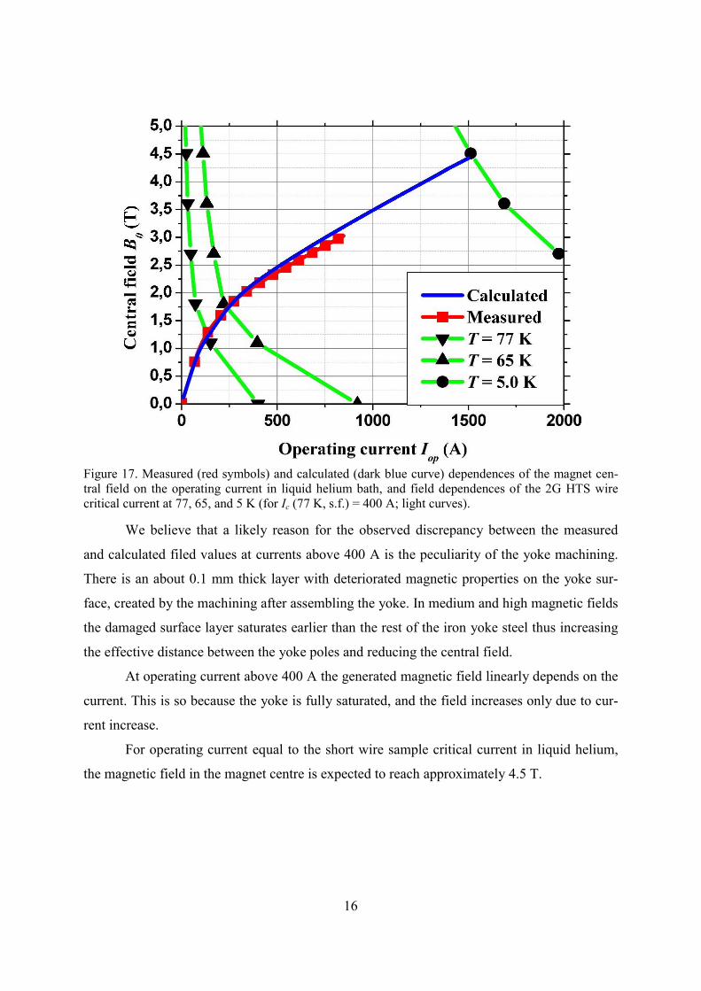
5.3. Measurements in Liquid Helium
In liquid helium the current was injected at a ramp rate of 2 A/s. The maximum in-
jected current was 847 A, and it was limited by the power supply. The magnetic field at this
current was 3.03 T. In next current ramp the maximum injected current was again 847 A and
any sign of the magnet quench is not seen. Figure 17 shows the measured and calculated de-
pendences of the magnet central field on the operating current in liquid helium.
16
Figure 17. Measured (red symbols) and calculated (dark blue curve) dependences of the magnet cen-tral field on the operating current in liquid helium bath, and field dependences of the 2G HTS wire critical current at 77, 65, and 5 K (for Ic (77 K, s.f.) = 400 A; light curves).
We believe that a likely reason for the observed discrepancy between the measured
and calculated filed values at currents above 400 A is the peculiarity of the yoke machining.
There is an about 0.1 mm thick layer with deteriorated magnetic properties on the yoke sur-
face, created by the machining after assembling the yoke. In medium and high magnetic fields
the damaged surface layer saturates earlier than the rest of the iron yoke steel thus increasing
the effective distance between the yoke poles and reducing the central field.
At operating current above 400 A the generated magnetic field linearly depends on the
current. This is so because the yoke is fully saturated, and the field increases only due to cur-
rent increase.
For operating current equal to the short wire sample critical current in liquid helium,
the magnetic field in the magnet centre is expected to reach approximately 4.5 T.

17
Conclusion
The HTS dipole magnet with 1-T central field in a 80×40 mm2 aperture have been de-
signed, fabricated and successfully tested by IHEP. The coil of this dipole was wounded, us-
ing the 2G HTS wire, produced by SuperOx.
At 77 K the current in the HTS coil reached 113 A, which corresponds to central field
of 1.12 T. At 65 K the HTS coil current was 228 A and the central field was 1.66 T. In liquid
helium bath the maximum injected current of 847 A was limited by the power supply and the
central field was 3.03 T.
These results show good promise for the use of liquid nitrogen, cooled HTS dipole
magnets in accelerators.
References
[1] H. Weijers, W. Markiewicz, A. Gavrilin, A. Voran, Y, Viouchkov, S. Gundlach, P. Noyes, D. Abraimov, H. Scott, T. Hannahs, and T. Murphy, Progress in the Develop-ment and Construction of a 32 T Superconducting Magnet, IEEE Trans. Appl. Super-cond., 26(4), 2016, 4300807.
[2] S. Yoon, J. Kim, K. Cheon, H. Lee, S. Hahn, S.-H. Moon, 26.4-T All HTS Magnet Wound with Multi-Width No-Insulation GdBCO Tape, presented at ISS 2015, No-vember 16-18, 2015, Tokyo, Japan.
[3] T. Huang, X. Gao, D. Pooke, V. Chamritski, N. Briggs, M. Christian, S. Gibson, J. Mitchell, M. Miles, and J. de Feijter, A Commercial HTS Dipole Magnet for X-Ray Magnetic Circular Dichroism (XMCD) Experiments, IEEE Trans. Appl. Supercond., 22(3), 2012, 4203504.
[4] J. Muratore, J. Escallier, G. Ganetis, A. K. Ghosh, R. C. Gupta, P. He, A. Jain, P.
Joshi, P. Wanderer, M. Fee, and M. Christian Magnetic Field Measurements of an HTS Retrofit Synchrotron Dipole, IEEE Trans. Appl. Supercond., 21(3), 2011, 1653.
[5] L. Bottura, The FCC Magnet Program: Challenges and Opportunities for HTS, Pre-
sented at WAMHTS-1, Hamburg, Germany, 21-23 May 2014, available online at: https://indico.cern.ch/event/308828/session/0/contribution/1/attachments/589800/811796/Opportunities_for_HTS_in_FCC.pdf

18
[6] G. Nielsen, N. Zangenberg, D. Hazelton, N. Hauge, B. R. Nielsen, S. P. Moller, A. Baurichter, Dipole Magnet from High Tc Superconductor, Physics Procedia 36 (2012 ) 824 – 829.
[7] G. A. Kirby, J. van Nugteren, A. Ballarino et al. Accelerator-Quality HTS Dipole Mag-
net Demonstrator Designs for the EuCARD-2 5-T 40-mm Clear Aperture Magnet, IEEE Trans. Appl. Supercond., 25(3), 2015, 4000805.
[8] D. Dezhin, R. Ilyasov, S. Kozub et al. “Synchronous Motor with HTS-2G Wires”. Proceedings of EUCAS 2013, Genoa, Italy, September, 2013.
[9] S. Kozub, I. Bogdanov, D. Dezhin,E. Kashtanov, K. Kovalev, V. Shuvalov,
V. Smirnov, V. Sytnik, P. Shcherbakov, L. Tkachenko. “HTS Racetrack Coils for Electrical Machines”. Proceedings of Cryogenics 2014, Prague, April, 2014.
[10] D. Dezhin, K. Kovalev, L. Verzhbitsky, S. Kozub,V. Firsov. "Design and Testing of
200 kW Synchronous Motor with 2G HTS Field Rotor Coils". Proceedings of EUCAS 2015, Lyon, France, September, 2015.
[11] K. Kovalev, V. Poltavets, R. Ilyasov, L. Verzhbitsky, S. Kozub. "1 MW HTS 2G Gen-
erator for Wind Turbines". Proceedings of EUCAS 2015, Lyon, France, September, 2015.
[12] S. Lee, V. Petrykin, A. Molodyk, S. Samoilenkov, A. Kaul, A. Vavilov, V. Vysotsky
and S. Fetisov, 2014 Development and Production of Second Generation High T-c Su-perconducting Tapes at SuperOx and First Tests of Model Cables Supercond. Sci. Technol. 27 044022.
[13] A. Kaul et al., “MOCVD Buffer and Superconducting Layers on Non-magnetic Biaxi-
ally Textured Tape for Coated Conductor Fabrication”, IEEE Trans. Appl. Supercond., 23, 2013, 6601404.
[14] C.Senatore et al., “Field and Temperature Scaling of the Critical Current Density in
Commercial REBCO Coated Conductors”, Supercond. Sci. Technol., 29, 2015, 014002. http://iopscience.iop.org/article/10.1088/0953-2048/29/1/014002/meta
[15] S. Samoilenkov, A. Molodyk, S. Lee, V. Petrykin, V. Kalitka, I. Martynova, A. Maka-
revich, A. Markelov, M. Moyzykh, A. Blednov, “Customized 2G HTS Wire for Ap-plications”, Supercond. Sci. Technol., 29, 2016, 024001.
[16] Results of Independent Measurements of SuperOx 2G HTS Wire in Digital Format
2012-2015, available online at http://www.superox.ru/en/products/42-2G-HTS-tape/ [17] I. Bogdanov, S. Kozub, P. Shcherbakov, L. Tkachenko, E. Fischer, F. Klos, G. Moritz,
C. Muehle. “Study of Electrical Steel Magnetic Properties for Fast Cycling Magnets of SIS100 and SIS300 Rings”, EPAC-2004, Lucerne, Switzerland, 2004, pp.1741-1743.

19
[18] L.M. Tkachenko. Code Package MULTIC for Calculation of Magnetic Field with an
Arbitrary Configuration. IHEP preprint 98-28, Protvino, 1998 (in Russian).
Received April 25, 2016.

И.В. Богданов, С.С. Козуб, В.М. Смирнов и др. ВТСП дипольный магнит. Препринт отпечатан с оригинала-макета, подготовленного авторами. Подписано к печати 26.04.2016. Формат 60 × 84/16. Цифровая печать. Печ.л. 1,5. Уч.− изд.л. 2,016. Тираж 80. Заказ 9. Индекс 3649. ФГБУ ГНЦ ИФВЭ НИЦ «Курчатовский институт» 142281, Московская область, г. Протвино, пл. Науки, 1 www.ihep.ru; библиотека http://web.ihep.su/library/pubs/all-w.htm

Индекс 3649
П Р Е П Р И Н Т 2016-6,
ФГБУ ГНЦ ИФВЭ НИЦ «Курчатовский институт», 2016