htc vive tracker (2018) developer guidelines · · 2018-03-15interface usb 2.0 full speed ......
TRANSCRIPT

HTC VIVE Tracker (2018) Developer Guidelines
Ver. 1.0

Version Control
Version Number Version Date Version Reason
1.0 2018.03.14 Initial version for Vive Tracker (2018)
© 2018 HTC Corporation. All Rights Reserved. HTC, the HTC logo, Vive, the Vive logo, and all other HTC product and services names are the trademarks or registered trademarks of HTC Corporation and its affiliates in the U.S. and other countries.

Contents
Contents ................................................................................................................................. 1 Introduction ............................................................................................................................ 1
Use cases ....................................................................................................................................... 1 Hardware requirements .......................................................................................................... 3
Interface .......................................................................................................................................... 4 Radio frequency (RF) ...................................................................................................................... 5 Power ............................................................................................................................................. 6 Optics ............................................................................................................................................. 6 Docking ........................................................................................................................................... 7
Mechanical considerations ................................................................................................... 11 Apparel size .................................................................................................................................. 12 Main feature .................................................................................................................................. 13 Docking mechanism ...................................................................................................................... 14 Damping mechanism .................................................................................................................... 16 Accessory design .......................................................................................................................... 17 Coordinate system ........................................................................................................................ 23
Software components .......................................................................................................... 26 System requirements .................................................................................................................... 26 Accessory integration .................................................................................................................... 27 Unity integration ............................................................................................................................ 32 VIVE Trackers and Vive Roles ..................................................................................................... 41 Tracker on Unity or Unreal ............................................................................................................ 43 Firmware upgrade ......................................................................................................................... 43
FAQs .................................................................................................................................... 44

VIVE Tracker (2018) HTC Corporation
Developer Guidelines V1.0
03/14/2018
1 HTC Confidential and Proprietary
Introduction This document describes the development guidelines for VR accessory makers and content developers. It contains information on how to use the HTC VIVE Tracker (2018) to enable position tracking and transmission of specific data (with or without the HTC Vive VR system). VIVE Tracker (2018) can pair with HTC’s wireless dongle or use its USB interface to transfer tracking data to a PC. An accessory attached to Vive Tracker (2018) can:
Simulate buttons of the Vive controller through the underlying Pogo pin.
Use cases There are five use cases supported by VIVE Tracker (2018). Use Case 1: Track passive objects with a USB cable in VR. In this case, the dongle is not used, and VIVE Tracker (2018) connects with a PC by USB directly to transfer tracking data.
Figure: Use case 1 of VIVE Tracker (2018)
Use Case 2: Track passive objects using a USB cable interface in VR, with the accessory passing data to a PC through USB, BT/Wi-Fi or propriety RF. This case is similar to Use Case 1, but the accessory transfers data to PC directly for a specific purpose based on its design.
Figure: Use case 2 of VIVE Tracker (2018)
Use Case 3: Track moving objects by wireless interface in VR. In this case, the dongle is used to transfer tracking data from the VIVE Tracker (2018) to a PC.

VIVE Tracker (2018) HTC Corporation
Developer Guidelines V1.0
03/14/2018
2 HTC Confidential and Proprietary
Figure: Use case 3 of VIVE Tracker (2018)
Use Case 4: Track moving objects using a wireless interface in VR, with the accessory passing data to a PC via USB, BT/Wi-Fi or propriety RF. This case is similar to Use Case 3, but the accessory transfers data to/from a PC directly for a specific purpose based on its design.
Figure: Use case 4 of VIVE Tracker (2018)
Use Case 5: Track moving objects using a wireless interface in VR, with the accessory simulating buttons of the Vive controller or passing data to a PC via the VIVE Tracker (2018). This case is similar to Use Case 3, but the accessory connects with the VIVE Tracker (2018) to transfer button event to a PC by Pogo pin.
Figure: Use case 5 of VIVE Tracker (2018)

VIVE Tracker (2018) HTC Corporation
Developer Guidelines V1.0
03/14/2018
3 HTC Confidential and Proprietary
Hardware requirements This section describes hardware requirements for accessories used with the VIVE Tracker (2018) in order to enable position tracking and input of specific data for the HTC Vive VR system. A compatible accessory may be attached to the VIVE Tracker (2018) to trigger specific event to a PC through the POGO interface of the VIVE Tracker (2018). The VIVE Tracker (2018) needs to pair with the dongle to transfer event to a PC. The figure below describes the conceptual architecture.
Figure: Conceptual Architecture of VIVE Tracker (2018)
Accessory VIVE
Tracker (2018)
Dongle PC POGO USB Wireless

VIVE Tracker (2018) HTC Corporation
Developer Guidelines V1.0
03/14/2018
4 HTC Confidential and Proprietary
Interface USB 2.0 full speed (client) from micro USB connector.
Absolute Maximum Rating
Symbol Parameter Min Max Unit
VI Input voltage - 0.5 3.6 V
VESD Electrostatic discharge voltage , Human Body Model -- 4000 V
Electrical Characteristics (Supply voltage VDD = 3.3 V)
Symbol Parameter Min Typ Max Unit
VOH High-level output voltage VDD - 0.4 -- -- V
VOL Low-level output voltage -- -- 0.4 V
VIH High-level input voltage 0.7VDD -- -- V
VIL Low-level input voltage -- -- 0.3VDD V
IOH High-level output current 20 -- -- mA
IOL Low-level output current 4 -- -- mA
IIH High-level input current -- 0.5 10 nA
IIL Low-level input current -- 0.5 10 nA
Pin no. Type Description
1 Digital output General purpose output pin
2 GND Ground
3 Digital / Power input
General purpose input pin: Internal pull up resistor
to VDD, Active-low (Grip button)
Power input pin
4 Digital inputGeneral purpose input pin: Internal pull up resistor
to VDD, Active-low (Trigger button)
5 Digital inputGeneral purpose input pin: Internal pull up resistor
to VDD, Active-low (Trackpad button)
6 Digital inputGeneral purpose input pin: Internal pull up resistor
to VDD, Active-low (M enu button)
Micro USB connector Pogo pin
6 5 4 3 2 1

VIVE Tracker (2018) HTC Corporation
Developer Guidelines V1.0
03/14/2018
5 HTC Confidential and Proprietary
Radio frequency (RF) To establish a stable wireless connection between the VIVE Tracker (2018) and the dongle, the OTA performance of VIVE Tracker (2018) cannot downgrade to more than 3dB when an accessory is attached to the VIVE Tracker (2018). The following are recommendations for better RF performance: Except for essential parts, such as the 1/4’’ screw, electric connection pad (which connects with the Pogo pin), and related circuits of the electric connection pad, metal parts of the accessory should keep at least 30mm distance away from the antenna to avoid OTA performance reduction when the accessory is attached to VIVE Tracker (2018). The figure below illustrates the “keep out” area where only nonmetallic parts of the accessory should be inside (spherical radius=30mm and the center is antenna feed point).
Figure: Restricted Area of Antenna

VIVE Tracker (2018) HTC Corporation
Developer Guidelines V1.0
03/14/2018
6 HTC Confidential and Proprietary
Power
Micro USB Connector Voltage requirement Max Charging current Max Charging time
AC 5V+/-5%
1000 mA 2 hrs
PC 500 mA 3 hrs
Pogo Pin 3 Voltage requirement Max Charging current Max Charging time
PC 5V+/-5% 500 mA 3 hrs
Note AC: D+ short to D- PC: D+/D- communication
Table: Micro USB connector and Pogo pin indication
Optics
The field of view (FOV) of VIVE Tracker (2018) is 270 degrees. Avoid placing the structure within the view angle, since it will block responses from VIVE Tracker (2018) sensors when placed in that direction. If the docking part extends beyond the recommended placing cone, extra views will be blocked.
Figure: Docking part extends beyond recommended placing cone

VIVE Tracker (2018) HTC Corporation
Developer Guidelines V1.0
03/14/2018
7 HTC Confidential and Proprietary
Docking The following are requirements for docking compatibility:
a. The docking design of VIVE Tracker (2018) follows the ISO standard (ISO 1222:2010). Furthermore, VIVE Tracker (2018) has constraining features, such as the longer screw cannot fasten all the way in.
b. The user should be able to easily attach and detach VIVE Tracker (2018) with two hands. One hand holds VIVE Tracker (2018), and the other one holds the accessory.
c. The user should not be at risk of physical harm while attaching or detaching VIVE
Tracker (2018).
d. The user should be comfortable while attaching and detaching VIVE Tracker (2018).
e. The accessory attached with VIVE Tracker (2018) should be in the shape of a physical object to avoid hitting during operating.
f. VIVE Tracker (2018) should not be blocked by the accessory and affect the tracking performance.
g. It is strongly recommended that the accessory uses low reflection material for its outer
skin to avoid reflection interference with the tracking sensors, especially if the accessory needs to be placed within the tracking sensors' FOV area.
Docking embodiments Gun
Sword

VIVE Tracker (2018) HTC Corporation
Developer Guidelines V1.0
03/14/2018
8 HTC Confidential and Proprietary
It is recommended to design the mounting mechanism close to the hand-held area, and set up the length in the VR program.
Multi-purpose docking base Users are able to attach the VIVE Tracker (2018) to any object/surface that is intended to be tracked.
If the object/surface is smooth and stiff, it is recommended to use stronger adhesive tape for attaching the docking base to the specific object/surface (ex. 3M VHB tape).
If the object/surface is rough and soft, it is recommended to use a strap for tightening the docking base to the specific object/surface.

VIVE Tracker (2018) HTC Corporation
Developer Guidelines V1.0
03/14/2018
9 HTC Confidential and Proprietary
Improper VIVE Tracker (2018) placement may cause the accessory body to obstruct the tracking performance. The mounting distance between tracking FOV and the related accessory size is shown below:

VIVE Tracker (2018) HTC Corporation
Developer Guidelines V1.0
03/14/2018
10 HTC Confidential and Proprietary
No tracking area Recommended area to put docking
mechanism
270 degree tracking FOV

VIVE Tracker (2018) HTC Corporation
Developer Guidelines V1.0
03/14/2018
11 HTC Confidential and Proprietary
Mechanical considerations
This section describes the mechanical considerations for developers to build various accessories that are compatible to fit or mount with the VIVE Tracker (2018).
Figure: VIVE Tracker (2018)
VIVE Tracker (2018) HTC Corporation
Developer Guidelines V1.0
03/14/2018
12 HTC Confidential and Proprietary
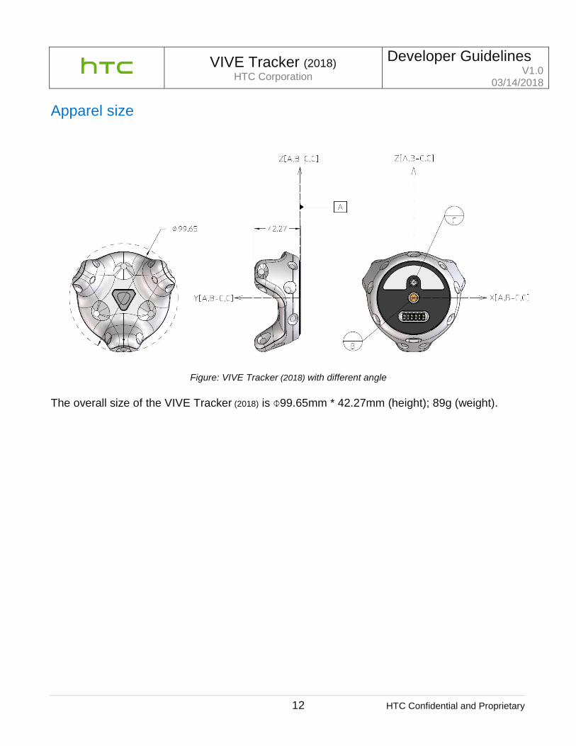
Apparel size
Figure: VIVE Tracker (2018) with different angle
The overall size of the VIVE Tracker (2018) is Ф99.65mm * 42.27mm (height); 89g (weight).

VIVE Tracker (2018) HTC Corporation
Developer Guidelines V1.0
03/14/2018
13 HTC Confidential and Proprietary
Main feature
Figure: Main features
1. LED Indicator: Shows the status of VIVE Tracker (2018).
2. Power Button: Used for powering on/off, BLE pairing, etc.
3. Sensor: Receives signals from the base stations. The VR system uses the received signals
for computing the current location of VIVE Tracker (2018). Accessory should minimize surface reflection (e.g. avoid white color surface) since it may cause faulty signal and affect performance. Anti-reflection painting is preferred.
4. Docking Mechanism: Standard camera tripod docking method is used which is comprised of: 4.1 1/4” Screw nut to fasten the accessory. 4.2 Stabilizing pin recess for constraining the tracking from rotation. 4.3 Pogo pin port (spring contact-type) for optional electrical connection to the accessory. 4.4 Friction pad for providing steady friction between the accessory and VIVE Tracker
(2018) 5. USB Port: Used for electrical connection to the accessory through a micro USB cable.
3. Sensors
1. LED Indicator
2. Power Button
5. USB Port
4.3 Pogo Pin (6 pins)
4.1 Standard Camera Mount (1/4” Screw Nut)
4.2 Stabilizing Pin Recess
4.4 Friction Pad

VIVE Tracker (2018) HTC Corporation
Developer Guidelines V1.0
03/14/2018
14 HTC Confidential and Proprietary
Docking mechanism VIVE Tracker (2018) applies the general camera tripod docking method, which follows ISO standards (ISO 1222:2010). The following are the schematic drawings of how the accessory will mount to the VIVE Tracker (2018).
Docking with standard tripod cradle head (w/o electric connection)
Figure: Docking with standard tripod cradle
VIVE Tracker (2018) can be mounted on the cradle head first, and then attached to the main body of the accessory (similar to how a camera is mounted on a tripod).
1/4” Bolt Stabilizing Pin
Friction Pad

VIVE Tracker (2018) HTC Corporation
Developer Guidelines V1.0
03/14/2018
15 HTC Confidential and Proprietary
Docking with side tightening wheel (w/ electric connection if needed)
Figure: Docking with side tightening wheel
In this example, the mechanical method allows developers to tighten the docking screw through the side spinning wheel. It is recommended that the spinning wheel should have a larger diameter (25 mm or greater) for better operation. This example is able to use the Pogo pin for extending the electric connection to somewhere else.
1/4” Bolt
Stabilizing Pin
Friction Pad
Spinning Wheel
Pogo Pin Pad (Optional)
Electric Connection Pad
(Optional)

VIVE Tracker (2018) HTC Corporation
Developer Guidelines V1.0
03/14/2018
16 HTC Confidential and Proprietary
Damping mechanism
During research and actual usage, it has been observed that continuous vibration in VIVE Tracker (2018) will affect the IMU performance, causing noticeable IMU drift. To address this, it is suggested to use a damping system with the docking mechanism. The illustration below is a reference for how existing damping rubbers (purchased as a drone accessory) can serve the purpose.
When considering the vibration level that the VR content plans to adopt, among the factors that can be adjusted are the durometer of the damper rubber, the mounting distance/position, and the usage of damper rubbers.
Docking Mechanism
Damper rubbers (*n)
Features on Accessory

VIVE Tracker (2018) HTC Corporation
Developer Guidelines V1.0
03/14/2018
17 HTC Confidential and Proprietary
Accessory design Below are the different accessory mechanisms, following ISO standards:
1/4” bolt design Please refer to ISO 1222-2010, Figure 1 on page 1.
Stabilizing pin design VIVE Tracker (2018) leverages the design from ISO 1222-2010, Figure 5 on page 3. For details on dimensions and tolerances, please refer to pages 13-17. It is suggested to apply the Stabilizing Pin for better tracking performance.
Screw thread design The screw thread type that applies to VIVE Tracker (2018) is 1/4” screw with 1.27 mm pitch. For detailed information, please refer to ISO 1222-2010, pages 3-5.

VIVE Tracker (2018) HTC Corporation
Developer Guidelines V1.0
03/14/2018
18 HTC Confidential and Proprietary
Design of Pogo Pin Pad
a. Pin definition (VIVE Tracker (2018))

VIVE Tracker (2018) HTC Corporation
Developer Guidelines V1.0
03/14/2018
19 HTC Confidential and Proprietary
b. Pogo Pin Pad reference design Electrical

VIVE Tracker (2018) HTC Corporation
Developer Guidelines V1.0
03/14/2018
20 HTC Confidential and Proprietary
Mechanical

VIVE Tracker (2018) HTC Corporation
Developer Guidelines V1.0
03/14/2018
21 HTC Confidential and Proprietary

VIVE Tracker (2018) HTC Corporation
Developer Guidelines V1.0
03/14/2018
22 HTC Confidential and Proprietary

VIVE Tracker (2018) HTC Corporation
Developer Guidelines V1.0
03/14/2018
23 HTC Confidential and Proprietary
Coordinate system VIVE Tracker (2018) uses the “Right-handed coordinate system”.
VIVE Tracker (2018)
Datum A is set to be the top surface of the ring feature around the 1/4” Screw Nut.
Datum B is set to be the intersection point between the centerline of Standard Camera Mount (1/4” Screw Bolt) and Datum A.
Datum C is set to be the intersection point between the centerline of Stabilizing Pin
Recess and Datum A.
The coordinate system is constructed by the Datum frame of Datum A, the line of Datum B and Datum C, and Datum C itself.

VIVE Tracker (2018) HTC Corporation
Developer Guidelines V1.0
03/14/2018
24 HTC Confidential and Proprietary

VIVE Tracker (2018) HTC Corporation
Developer Guidelines V1.0
03/14/2018
25 HTC Confidential and Proprietary
Accessory:
Datum A is set to be the top surface of the ring feature around the 1/4” Bolt.
Datum B is set to be the intersection point between the centerline of 1/4” Screw and
Datum A.
Datum C is set to be the intersection point between the centerline of Stabilizing Pin and Datum A.
The coordinate system is constructed by the Datum frame of Datum A, the line of
Datum B and Datum C, and Datum C itself.
VIVE Tracker (2018) HTC Corporation
Developer Guidelines V1.0
03/14/2018
26 HTC Confidential and Proprietary
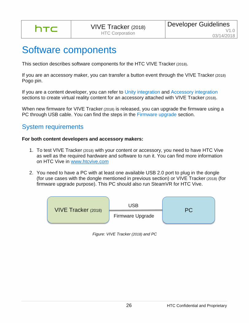
Software components
This section describes software components for the HTC VIVE Tracker (2018). If you are an accessory maker, you can transfer a button event through the VIVE Tracker (2018) Pogo pin. If you are a content developer, you can refer to Unity integration and Accessory integration sections to create virtual reality content for an accessory attached with VIVE Tracker (2018). When new firmware for VIVE Tracker (2018) is released, you can upgrade the firmware using a PC through USB cable. You can find the steps in the Firmware upgrade section.
System requirements For both content developers and accessory makers:
1. To test VIVE Tracker (2018) with your content or accessory, you need to have HTC Vive as well as the required hardware and software to run it. You can find more information on HTC Vive in www.htcvive.com
2. You need to have a PC with at least one available USB 2.0 port to plug in the dongle
(for use cases with the dongle mentioned in previous section) or VIVE Tracker (2018) (for firmware upgrade purpose). This PC should also run SteamVR for HTC Vive.
Figure: VIVE Tracker (2018) and PC
VIVE Tracker (2018) PC USB
Firmware Upgrade

VIVE Tracker (2018) HTC Corporation
Developer Guidelines V1.0
03/14/2018
27 HTC Confidential and Proprietary
For accessory makers:
If your accessory needs to simulate buttons of the Vive controller or transfer data to a PC through VIVE Tracker (2018), it must support the following interfaces respectively: Pogo pin Refer to hardware requirement section for detailed information on button simulation.
Accessory integration For Pogo out pin signal duration: VIVE Tracker (2018) receives haptic input value from the content, while the Pogo out pin will output HIGH with the duration value in “ms”. This section describes information on position transformation between an accessory and VIVE Tracker (2018). Content developers can create the correct rotation and translation result of the content used with the attached accessory in a game engine such as Unity. It is assumed that the local coordinate system of the accessory is z-axis facing the front (left-handed coordinate system), and VIVE Tracker (2018) is attached in the accessory as in the example below. Rotation degree and translation distance of an accessory relevant to VIVE Tracker (2018) are described in roll, yaw, pitch and Dx, Dy, Dz respectively during the integration. After the center of an accessory has been decided during the design, the following degrees and distance of an accessory based on actual integration condition can be measured. For detailed information regarding the center of the VIVE Tracker (2018), refer to guidelines related to the hardware and mechanical design.

VIVE Tracker (2018) HTC Corporation
Developer Guidelines V1.0
03/14/2018
28 HTC Confidential and Proprietary
An example of using a gun as an accessory is described in the figure below:
Figure: Example to integrate accessory and VIVE Tracker (2018)

VIVE Tracker (2018) HTC Corporation
Developer Guidelines V1.0
03/14/2018
29 HTC Confidential and Proprietary
Pitch : Angle that rotate around x axis in degrees Yaw : Angle that rotate around y axis in degrees Roll : Angle that rotate around z axis in degrees Dx : Center distance of x axis between accessory and tracker Dy : Center distance of y axis between accessory and tracker Dz : Center distance of z axis between accessory and tracker
Content developers can collect the above information and transform Tracker pose to accessory pose. Assume Tracker rotation matrix is 𝑅𝑇𝑟𝑎𝑐𝑘𝑒𝑟, accessory rotation matrix 𝑅𝐴𝑐𝑐𝑒𝑠𝑠𝑜𝑟𝑦 =
𝑅𝑃𝑖𝑡𝑐ℎ_𝑌𝑎𝑤_𝑅𝑜𝑙𝑙 ∗ 𝑅𝑇𝑟𝑎𝑐𝑘𝑒𝑟.
And accessory position 𝑉𝐴𝑐𝑐𝑒𝑠𝑠𝑜𝑟𝑦= 𝑉𝑇𝑟𝑎𝑐𝑘𝑒𝑟+ 𝑅𝐴𝑐𝑐𝑒𝑠𝑠𝑜𝑟𝑦*𝐷𝑖𝑠𝑡𝑎𝑛𝑐𝑒

VIVE Tracker (2018) HTC Corporation
Developer Guidelines V1.0
03/14/2018
30 HTC Confidential and Proprietary
The following is a Unity sample code (reference):
Figure: Unity sample code for accessory integration (1)
public class Accessory : MonoBehaviour { const float dX = 0.0100224f; const float dY = -0.07616526f; const float dZ = 0.4884118f; const float roll = 10.854305f; const float yaw = 91.8736f; const float pitch = 78.805113f;
void Update () { //Collect delta rotation and displacement between Tracker and Accessory Vector3 delta_displacement = new Vector3(dX, dY, dZ); Quaternion delta_rotation = Quaternion.Euler(roll, yaw, pitch); //Get current Tracker pose Vector3 tracker_position = SteamVR_Controller.Input(3).transform.pos; Quaternion tracker_rotation = SteamVR_Controller.Input(3).transform.rot; //Transform current Tracker pose to Accessory pose GameObject.Find("Accessory ").transform.rotation = tracker_rotation * delta_rotation; GameObject.Find("Accessory ").transform.position = tracker_position + (tracker_rotation * delta_rotation) * delta_displacement; } }

VIVE Tracker (2018) HTC Corporation
Developer Guidelines V1.0
03/14/2018
31 HTC Confidential and Proprietary
Another Unity sample code shows how to transform the accessory by comparing vectors parallel to y-axis and z-axis of the VIVE Tracker (2018) (AxisY_Tracker, AxisZ_Tracker in example below) and the accessory (AxisY_Accessory, AxisZ_Accessory in example below).
Figure: Unity sample code for accessory integration (2)
public class Accessory : MonoBehaviour { const Vector3 AxisY_Tracker = new Vectors(AxisY_Tracker_X, AxisY_Tracker_Y, AxisY_Tracker_Z); const Vector3 AxisZ_Tracker = new Vectors(AxisZ_Tracker_X, AxisZ_Tracker_Y, AxisZ_Tracker_Z); const Vector3 AxisY_Accessory = new Vectors(AxisY_ Accessory _X, AxisY_ Accessory _Y, AxisY_ Accessory _Z); const Vector3 AxisZ_ Accessory = new Vectors(AxisZ_ Accessory _X, AxisZ_ Accessory _Y, AxisZ_ Accessory _Z);
void Update () { //Calculate delta rotation by comparing vectors parallel to Y axes of Tracker and the accessory Quaternion delta_rotY = Quaternion.FromToRotation(AxisY_Tracker, AxisY_Accessory); AxisZ_Tracker = delta_rotY * AxisZ_Tracker; Quaternion delta_rotZ = Quaternion.FromToRotation(AxisZ_Tracker, AxisZ_Accessory); //Collect delta rotation and displacement between Tracker and Accessory Vector3 delta_displacement = new Vector3(dX, dY, dZ); Quaternion delta_rotation = delta_rotZ * delta_rotY; //Get current Tracker pose Vector3 tracker_position = SteamVR_Controller.Input(3).transform.pos; Quaternion tracker_rotation = SteamVR_Controller.Input(3).transform.rot; //Transform current Tracker pose to Accessory pose GameObject.Find("Accessory ").transform.rotation = delta_rotation * tracker_rotation; GameObject.Find("Accessory ").transform.position = tracker_position + (delta_rotation * tracker_rotation) * delta_displacement; } }

VIVE Tracker (2018) HTC Corporation
Developer Guidelines V1.0
03/14/2018
32 HTC Confidential and Proprietary
Unity integration
This section provides an example for content developers to enable VIVE Tracker (2018) in VR content by using Unity game engine. First, you need to make VIVE Tracker (2018) detectable in SteamVR. Assume that you have two Vive controllers already, and you have plugged in the dongle into the dongle cradle to the computer’s USB port. Right-click on one of the existing controller’s icon and click “Pair Controller” in the pop-up menu (shown in figure below). Press the Power button on VIVE Tracker (2018) for 2 seconds, and then release it to enter the paring mode.
Figure: Pair VIVE Tracker (2018)
After paring is successful between the VIVE Tracker (2018) and the dongle, you will see that the Vive Tracker is detected in the SteamVR UI.
Figure: VIVE Tracker (2018) is added in SteamVR

VIVE Tracker (2018) HTC Corporation
Developer Guidelines V1.0
03/14/2018
33 HTC Confidential and Proprietary
It is recommended that you use Unity 2017.3 or 2018.1 (minimum version 5.3.5) from: https://unity3d.com/get-unity/download
Using the SteamVR plugin: You need to import SteamVR Plugin into your project first. If you do not have it yet, you can download it from the Asset Store in Unity.
Figure: Unity Asset Store: SteamVR Plugin

VIVE Tracker (2018) HTC Corporation
Developer Guidelines V1.0
03/14/2018
34 HTC Confidential and Proprietary
In the developer version of VIVE Tracker (2018), it will use a similar approach and naming as you did to create content for the Vive controller. The steps to create content for VIVE Tracker (2018) are as follows (with figures from Unity): Step 1: Add “CameraRig” to Hierarchy to start creating content for SteamVR in Unity.
Figure: Add “CameraRig”

VIVE Tracker (2018) HTC Corporation
Developer Guidelines V1.0
03/14/2018
35 HTC Confidential and Proprietary
Step 2: Create the 3D Object for Vive Tracker (2018). In this example, “Capsule” is used.
Figure: Create 3D Object
VIVE Tracker (2018) HTC Corporation
Developer Guidelines V1.0
03/14/2018
36 HTC Confidential and Proprietary
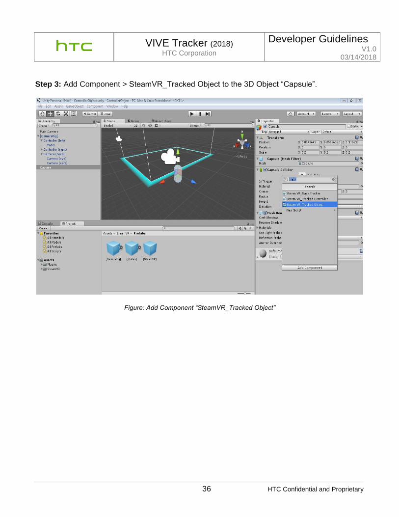
Step 3: Add Component > SteamVR_Tracked Object to the 3D Object “Capsule”.
Figure: Add Component “SteamVR_Tracked Object”

VIVE Tracker (2018) HTC Corporation
Developer Guidelines V1.0
03/14/2018
37 HTC Confidential and Proprietary
Step 4: Under SteamVR Controller Manager, set the size of the Objects item. In this example, one VIVE Tracker (2018) is used in the setup.
Figure: Set size of object in “SteamVR Controller Manager”

VIVE Tracker (2018) HTC Corporation
Developer Guidelines V1.0
03/14/2018
38 HTC Confidential and Proprietary
Step 5: Under SteamVR Controller Manager, on the Element 0 field, select “Capsule” as the GameObject.
Figure: Set type of object in “SteamVR Controller Manager”

VIVE Tracker (2018) HTC Corporation
Developer Guidelines V1.0
03/14/2018
39 HTC Confidential and Proprietary
Step 6: After completing the steps mentioned above, press the “Run” button in Unity. When you move VIVE Tracker (2018), you will see the Capsule object is also moving in the content.
Figure: Execution of Unity
Using VIVE Unity plugin:

VIVE Tracker (2018) HTC Corporation
Developer Guidelines V1.0
03/14/2018
40 HTC Confidential and Proprietary
You need to import the VIVE Input Utility plugin into your project first. If you do not have it yet, you can download it from the Asset Store in Unity. The VIVE Input Utility (VIU) plugin is a cross platform VR toolkit with additional support or the VIVE Trackers.
Figure: Unity Asset Store: VIVE Input Utility
Step 1: Add “ViveCameraRig” or "ViveRig" to scene Hierarchy to add support for controllers and trackers in Unity.
Figure: adding a ViveRig prefab to your scene.
Step 2. Just as with SteamVR's "CameraRig", you may remove the existing "Camera" from the scene because the rig includes a camera.
VIVE Tracker (2018) HTC Corporation
Developer Guidelines V1.0
03/14/2018
41 HTC Confidential and Proprietary
Step 3. Run to see the trackers supported just like the controllers. You will see the models from SteamVR if you also included the SteamVR plugin, otherwise you will see included models. The ViveRig and ViveCameraRig prefabs include support for up to three trackers. To add additional trackers, simply duplicate a tracker and rename the game object. In the inspector, make sure to also update the ViveRole. Note: Currently in both SteamVR and VIU, there is support for up to 11 (or 13, if not using controllers) from a total of 16 devices (including the hmd and base stations). Recently OpenVR has been updated to support up to 64 devices, but this has not been updated yet in the Unity plugins (but developers can add support with their own code).
VIVE Trackers and Vive Roles One of the benefits of using the Vive Input Utility is that you can swap VIVE trackers or redefine where they are attached to without worrying about managing device IDs and serial numbers. You can now assign Vive Roles depending on the context: TrackerRole, BodyRole, HandRole and DeviceRole. For example, you can define that the same specific VIVE tracker device is always assigned to your left foot using BodyRole LeftFoot. You can also assign to trackers to the same role to make it easier to swap out tracker devices when one is low on battery. The Vive Input Utility also provides a tool to discover and assign roles without additional code.

VIVE Tracker (2018) HTC Corporation
Developer Guidelines V1.0
03/14/2018
42 HTC Confidential and Proprietary
There is a shortcut keyboard key, which can be assigned to display this overlay UI:

VIVE Tracker (2018) HTC Corporation
Developer Guidelines V1.0
03/14/2018
43 HTC Confidential and Proprietary
Additionally, there is an API available to create your own VR UI for assigning roles. For more information is the following article https://github.com/ViveSoftware/ViveInputUtility-
Unity/wiki/ViveRole. An example project is included with the VIU plugin as
"7.RoleBindingExample.
Tracker on Unity or Unreal
If you encounter problems in enabling VIVE Tracker (2018) on Unity or Unreal, refer to the following links:
For Unity 3D developers: o Download link for the ViveInputUtility package: AssetStore or GitHub o Vive Input Utility source code repository:
https://github.com/ViveSoftware/ViveInputUtility-Unity
For Unreal Engine 4 developers: o Check that you’re using Unreal Engine version 4.17 or later
Firmware upgrade Follow the SteamVR notification to update the firmware. You may also do these steps to upgrade the VIVE Tracker (2018) firmware:
1. Copy the firmware binary files (including MCU, FPGA and RF) provided by HTC into the same folder of “lighthouse_watchman_update.exe” in your PC.
2. If a Vive controller is connected to your computer via USB, unplug it first. 3. Connect one VIVE Tracker (2018) with your computer using the USB cable. 4. Execute the following commands.
a. Update MCU’s firmware:
lighthouse_watchman_update --target=default watchman_v3.fw
b. Update FPGA’s firmware:
lighthouse_watchman_update.exe --target=default ice40_hdk_xxx.fw
c. Update RF’s firmware:
lighthouse_watchman_update --target=default nrf52_xxx.fw

VIVE Tracker (2018) HTC Corporation
Developer Guidelines V1.0
03/14/2018
44 HTC Confidential and Proprietary
FAQs
Type No. Question Answer
Common 1 How do I connect the dongle to my computer?
Connect one end of the supplied USB cable to the dongle cradle, and then attach the dongle to the cradle. Connect the other end of the USB cable to your computer.
2 How do I charge VIVE Tracker (2018)?
While in VR, you can check the battery level of VIVE Tracker (2018) when no apps are running, or when the System Dashboard is up. When the battery is low, the indicator will show a single red dot. Make sure to use the USB cable that’s in the box. Connect the USB cable to the power adapter that came with your Vive controllers, and then plug the power adapter to a power outlet to charge VIVE Tracker (2018). You can also connect VIVE Tracker (2018) to a computer’s USB port to charge it. When VIVE Tracker (2018) is fully charged, its status light either shows white if it is off or green if it is turned on.
3 How do I pair the dongle with VIVE Tracker (2018)?
1. Turn on the headset and pair the2 controllers. 2. Connect the dongle to your computer. 3. Turn on Vive Tracker (2018) to start the pairing
process To manually pair VIVE Tracker (2018), open the SteamVR app, tap the down arrow, and then select Devices > Pair Controller. Follow the on-screen instructions to complete the process.
4 What does the status light on VIVE Tracker (2018) mean?
The status light shows:
Green when VIVE Tracker (2018) is in normal mode
Blinking red when battery is low
Blinking blue when VIVE Tracker (2018) is pairing with the headset or dongle
Blue when VIVE Tracker (2018) is connecting with the headset or dongle
Orange when charging

VIVE Tracker (2018) HTC Corporation
Developer Guidelines V1.0
03/14/2018
45 HTC Confidential and Proprietary
5 How can I update VIVE Tracker (2018)?
1. From your computer, open the SteamVR app. 2. Using the supplied USB cable, connect the VIVE
Tracker (2018) to one of your computer’s USB ports. The firmware update will start automatically once tracker is detected by SteamVR. Warning: Do not unplug the micro-USB cable any time before the firmware update is complete. Doing so could result in a firmware error.
3. When the update is complete, click Done.
6 Why does VIVE Tracker (2018) automatically turn off?
When VIVE Tracker (2018) turns off, some of the possible reasons might be:
The battery is drained
Pairing has timed out after being idle for more than 30 seconds
There was no user movement for 5 minutes
7 Can I use more than one VIVE Tracker (2018)? How many trackers can be adapted?
Yes. The maximum number of tracking objects that can be adopted is 11 units of Vive Tracker, plus 2 Vive controllers.
8 Why can't I see VIVE Tracker (2018) on SteamVR?
Check that your SteamVR app is the latest version.

VIVE Tracker (2018) HTC Corporation
Developer Guidelines V1.0
03/14/2018
46 HTC Confidential and Proprietary
Type No. Question Answer
SDK 1 How do identify whether VIVE Tracker (2018) or the controller is being tracked?
You can use the class type of SteamVR SDK to identify if VIVE Tracker (2018) or the controller is currently being tracked.
2 Does VIVE Tracker (2018) have a different coordination system compared to the controllers?
Yes. Content developers need to apply different coordination settings based on the position where the VIVE Tracker (2018) is mounted.
3 How can I replace the controller with VIVE Tracker (2018) if I already created content meant for the controller?
Content developers need to apply different coordination settings based on whether VIVE Tracker (2018) is mounted on the same position as the controller. If its position is different, content developers need to recalibrate for VIVE Tracker (2018).
4 What's the equivalent of VIVE Tracker (2018)'s hardware button to the controller?
The hardware button of VIVE Tracker (2018) maps to the System button of the controller.
5 Why is tracking lost when I connected VIVE Tracker (2018) to a USB cable?
When you connect VIVE Tracker (2018) to your computer using a USB cable, it enters data sending mode that sending tracking data to computer via USB.
Type No. Question Answer
Hardware 1 What is in the downloadable 3D CAD file for the Vive Tracker (2018)?
The 1,777KB ZIP package contains the .IGS and .STP files for Vive Tracker (2018). It is not a requirement to use the files, but it can help if you have a 3D modeling software. For details, go to http://link.vive.com/tracker/3d_model