hsupa design library -...
TRANSCRIPT
HSUPA Design Library
January 2007

Notice
The information contained in this document is subject to change without notice.
Agilent Technologies makes no warranty of any kind with regard to this material, including, but not limited to, the implied warranties of merchantability and fitness for a particular purpose. Agilent Technologies shall not be liable for errors contained herein or for incidental or consequential damages in connection with the furnishing, performance, or use of this material.
Warranty
A copy of the specific warranty terms that apply to this software product is available upon request from your Agilent Technologies representative.
Restricted Rights Legend
Use, duplication or disclosure by the U. S. Government is subject to restrictions as set forth in subparagraph (c) (1) (ii) of the Rights in Technical Data and Computer Software clause at DFARS 252.227-7013 for DoD agencies, and subparagraphs (c) (1) and (c) (2) of the Commercial Computer Software Restricted Rights clause at FAR 52.227-19 for other agencies.
© Agilent Technologies, Inc. 1983-2007. 395 Page Mill Road, Palo Alto, CA 94304 U.S.A.
Acknowledgments
Mentor Graphics is a trademark of Mentor Graphics Corporation in the U.S. and other countries.
Microsoft®, Windows®, MS Windows®, Windows NT®, and MS-DOS® are U.S. registered trademarks of Microsoft Corporation.
Pentium® is a U.S. registered trademark of Intel Corporation.
PostScript® and Acrobat® are trademarks of Adobe Systems Incorporated.
UNIX® is a registered trademark of the Open Group.
Java™ is a U.S. trademark of Sun Microsystems, Inc.
SystemC® is a registered trademark of Open SystemC Initiative, Inc. in the United States and other countries and is used with permission.
MATLAB® is a U.S. registered trademark of The Math Works, Inc.
ii

Contents1 HSUPA Design Library
3GPP Technical Specifications Supported ............................................................... 1-1HSUPA Systems....................................................................................................... 1-1Specifications for E-DCH and E-DPDCH.................................................................. 1-3HSUPA Component Libraries Overview ................................................................... 1-3Design Examples...................................................................................................... 1-5Glossary of Terms..................................................................................................... 1-6References ............................................................................................................... 1-7
2 HSUPA ComponentsHSPA_Channel......................................................................................................... 2-2HSUPA_BER_Throughput........................................................................................ 2-7HSUPA_Bits ............................................................................................................. 2-10HSUPA_ChDecode .................................................................................................. 2-13HSUPA_ChEncode................................................................................................... 2-15HSUPA_CodeBlkDeseg ........................................................................................... 2-17HSUPA_CodeBlkSeg ............................................................................................... 2-19HSUPA_Deinterleaver .............................................................................................. 2-21HSUPA_DL_Rake .................................................................................................... 2-23HSUPA_DL_Receiver............................................................................................... 2-28HSUPA_DL_ReceiverRF.......................................................................................... 2-33HSUPA_DL_Source ................................................................................................. 2-38HSUPA_DL_SourceRF............................................................................................. 2-45HSUPA_EAGCH....................................................................................................... 2-54HSUPA_EAGCH_Decode ........................................................................................ 2-58HSUPA_EAGCH_DeRM .......................................................................................... 2-60HSUPA_EAGCH_RM ............................................................................................... 2-62HSUPA_EDPCCH_ChDecode ................................................................................. 2-64HSUPA_EDPCCH_ChEncode ................................................................................. 2-66HSUPA_EHICH_ERGCH ......................................................................................... 2-68HSUPA_EHICH_ERGCH_Decode........................................................................... 2-70HSUPA_EVM............................................................................................................ 2-73HSUPA_FRC ............................................................................................................ 2-76HSUPA_FRC_Receiver............................................................................................ 2-79HSUPA_FRC_ReceiverRF ....................................................................................... 2-83HSUPA_FRC_RF ..................................................................................................... 2-87HSUPA_Interleaver .................................................................................................. 2-90HSUPA_OCNS ......................................................................................................... 2-92HSUPA_ParamCalc.................................................................................................. 2-95HSUPA_PhCH_Demap ............................................................................................ 2-97
iii

HSUPA_PhCH_Map................................................................................................. 2-99HSUPA_RateDematch ............................................................................................. 2-101HSUPA_RateMatch .................................................................................................. 2-104HSUPA_RF_EVM..................................................................................................... 2-107HSUPA_RF_OutputPower........................................................................................ 2-111HSUPA_SignatureSqn.............................................................................................. 2-114HSUPA_Spread ........................................................................................................ 2-119HSUPA_UL_Rake .................................................................................................... 2-123HSUPA_UL_Source ................................................................................................. 2-130HSUPA_UL_SourceRF............................................................................................. 2-133
3 HSUPA Base Station Receiver Design ExamplesIntroduction............................................................................................................... 3-1Demodulation Performance Measurements ............................................................. 3-2Signaling Detection Performance Measurements - False Alarm.............................. 3-6Signaling Detection Performance Measurements - Missed Detection ..................... 3-11
4 HSUPA User Equipment Receiver Design ExamplesIntroduction............................................................................................................... 4-1E-AGCH Demodulation Performance Measurements .............................................. 4-2E-HICH Detection Performance Measurements....................................................... 4-5E-RGCH Detection Performance Measurements..................................................... 4-9
5 HSUPA User Equipment Transmitter Design ExamplesIntroduction............................................................................................................... 5-1Adjacent Channel Leakage Power Ratio Measurements ......................................... 5-2CCDF and Peak-to-Mean Information Measurements ............................................. 5-6Error Vector Magnitude Measurements.................................................................... 5-9Maximum Power Measurements .............................................................................. 5-12Spectrum Emission Mask Measurements ................................................................ 5-14
Index
iv

Chapter 1: HSUPA Design LibraryThe HSUPA Design Library is designed for 3GPP FDD enhanced uplink, also known as HSUPA, defined in release 6 of 3GPP specification. This design library focuses on the physical layer aspects of HSUPA systems and is intended to be a baseline system for designers to get an idea of what nominal or ideal system performance would be. Evaluations can be made regarding degraded system performance due to system impairments that may include non-ideal component performance.
The transport channels and physical channels defined in release 5 and previous versions of 3GPP specification such as DCH, DPDCH are also supported by HSUPA design library. But they are treated as the accessory channels because HSUPA design library focus on the modeling and test of channels defined in release 6, say HSUPA. The test for the scenario with only 3GPP FDD with/without HSDPA can be implemented by 3GPP design library.
3GPP Technical Specifications Supported3GPP committee updates 3GPP technical specifications every 3 months. Each of 3GPP specification is further classified by features: release '99 (Version 3.x.x), release 4 (Version 4.x.x), release 5 (Version 5.x.x), release 6 (Version 6.x.x) release 7(Version 7.x.x). Basically, the contents defined in lower version specifications duplicate the contents from release '99, release 4 and release 5 that are published simultaneously.
The HSUPA design library is compliant with 3GPP release 6 technical specifications published in 2006-03.
HSUPA design library also reuses some 3GPP design library models in the application level. The technical specifications of those models were published in 2002-03 for release '99 content and 2003-09 for HSDPA part in release 5. The version may be changed if 3GPP design library is updated.
HSUPA SystemsHSUPA aims at providing significant enhancements in terms of user experience (throughput and delay) and/or capacity. It enables to achieve significant improvements in overall system performance when operated together with HSDPA. In other words, the aim of HSUPA is to enhance the uplink DCH operation and performance to support services like video-clips, multimedia, e-mail, telematics, gaming, video-streaming, and etc. At the same time, HSUPA is backward-compatible with 3GPP FDD with HSDPA defined in release 5 and previous versions of 3GPP specification.
3GPP Technical Specifications Supported 1-1

HSUPA Design Library
In the uplink, two new physical channels E-DPDCH and E-DPCCH are defined.
The HSUPA uplink transmitter and receiver structure block diagram for E-DPDCH is shown in Figure 1-1.
Figure 1-1. HSUPA Uplink Transceiver Physical Layer Block Diagram
In HSUPA downlink, three new channels E-AGCH, E-HICH and E-RGCH are defined. The HSUPA downlink physical layer structure is almost the same as 3GPP FDD with HSDPA defined in release 5 and previous released versions. All downlink physical channels including three new channels are spread, QPSK-mapped and scrambled separately and then combined as the downlink signal. The structure of downlink transmitter and receiver can be found in 3GPP design library.
1-2 HSUPA Systems

Specifications for E-DCH and E-DPDCHHSUPA E-DCH physical layer categories are shown in Table 1-1.
The physical channel parameters on E-DPDCH for E-DCH test are shown in Table 1-2.
HSUPA Component Libraries OverviewChannel Components
• Multipath fading channel
Channel Coding Components
Channel coding components accomplish the following functions.
• Turbo code as E-DCH forward error control code
• Revised TFCI Reed-Muller (RM) coding as E-DPCCH channel coding and signal quality indicator
Table 1-1. FDD E-DCH physical layer categories
E-DCH category
Maximum number of E-DPDCH transmitted
Minimum spreading factor of E-DPDCH
Support for 10 and 2 ms TTI E-DCH
Maximum number of bits of an E-DCH transport block transmitted within a 10 ms E-DCH TTI
Maximum number of bits of an E-DCH transport block transmitted within a 2 ms E-DCH TTI
Category 1 1 SF4 10 ms TTI only 7110 -
Category 2 2 SF4 10 ms and2 ms TTI
14484 2798
Category 3 2 SF4 10 ms TTI only 14484 -
Category 4 2 SF2 10 ms and2 ms TTI
20000 5772
Category 5 2 SF2 10 ms TTI only 20000 -
Category 6 4 SF2 10 ms and2 ms TTI
20000 11484
NOTE: When 4 codes are transmitted in parallel, two codes shall be transmitted with SF2 and two with SF4
Table 1-2. Physical channel parameters on E-DPDCH for E-DCH tests
TTI Number of processes
2 ms 8
10 ms 4
Specifications for E-DCH and E-DPDCH 1-3

HSUPA Design Library
• Orthogonal signature sequence as E-HICH/E-RGCH channel coding and signal quality indicator
• Rate match (puncturing and repetition) used to implement channel coding with flexible coding rate for E-DCH and E-AGCH
• Interleaving used to spread burst errors into random errors in order to improve the error correction code performance
Multiplex Components
• Code segmentation used to adjust code block to suitable size
• Physical channel mapping used to map E-DCH to E-DPDCH
• Uplink spreader used to spread, power-scale and multiplex various uplink channels
Measurement Components
• Throughput, BER and PER vs. retransmission time measurement
• Output power measurement as well as cubic metric calculator
• EVM and phase discontinuity measurements
Receiver Components
• Rake receivers for HSUPA uplink and downlink
• Baseband receivers for HSUPA uplink and downlink
• RF receiver for HSUPA uplink and downlink Base Station and User Equipment Components
Signal Source Components
• E-DCH information bit source which support HARQ process
• Uplink fixed reference channel in baseband and RF
• Uplink general signal source in baseband and RF
• Downlink signal source for E-AGCH and E-HICH/E-RGCH
• Downlink general signal source in baseband and RF
1-4 HSUPA Component Libraries Overview

Design ExamplesThe RF characteristics can be measured using the HSUPA design library. RF measurements for user equipment (UE) are defined in [5]; test methods are described in [8]. For base station (BS), the RF characteristics are defined in [6]; test methods are described in [7].
The HSUPA_BS_Rx_prj project shows base station receiver performance on E-DCH. Designs for these measurements include:
• E-DPDCH demodulation performance: BS_Rx_Demodulation.dsn
• E-DPDCH demodulation performance in fading channel: BS_Rx_DemodulationFading.dsn
• E-DPCCH missed detection: BS_Rx_MissedDetection.dsn
• E-DPCCH missed detection in fading channel: BS_Rx_MissedDetectionFading.dsn
• E-DPCCH false alarm: BS_Rx_FalseAlarm.dsn
• E-DPCCH false alarm in fading channel: BS_Rx_FalseAlarmFading.dsn
The HSUPA_UE_Rx_prj project shows HSUPA user equipment receiver performance. Designs for these measurements include:
• E-AGCH demodulation performance: UE_Rx_EAGCH_Demodulation.dsn
• E-AGCH demodulation performance in fading channel: UE_Rx_EAGCH_DemodulationFading.dsn
• E-HICH detection performance: UE_Rx_EHICH_Detection.dsn
• E-HICH detection performance in fading channel: UE_Rx_EHICH_DetectionFading.dsn
• E-RGCH detection performance: UE_Rx_ERGCH_Detection.dsn
• E-RGCH detection performance in fading channel: UE_Rx_ERGCH_DetectionFading.dsn
The HSUPA_UE_Tx_prj project demonstrates user equipment transmitter measurement characteristics. Designs for these measurements include:
• Adjacent channel leakage power ratio measurements: UE_Tx_ACLR.dsn
• CCDF and peak-to-mean information measurements: UE_Tx_CCDF.dsn
• Error vector magnitude and phase discontinuity measurements: UE_Tx_EVM.dsn
• Maximum power measurements: UE_Tx_Max_Power.dsn
• Spectrum emission measurements: UE_Tx_SpecEmissions.dsn
Design Examples 1-5

HSUPA Design Library
The HSUPA_RF_Verification_prj project has only one WTB-like design:
• HSUPA_UE_TX_test.dsn
Glossary of Terms
3GPP third generation partnership project
ACLR adjacent channel leakage power ratio
AWGN additive white Gaussian noise
CCDF complementary cumulative distribution function
DCH dedicated channel
DPDCH dedicated physical data channel
E-AGCH E-DCH absolute grant channel
E-DCH enhanced DCH
E-DPCCH E-DCH HARQ acknowledgement indicator channel
E-DPDCH E-DCH relative grant channel
E-HICH E-DCH dedicated physical control channel
E-RGCH E-DCH dedicated physical data channel
EVM error vector magnitude
FDD frequency division duplex
FEC forward error correction
HSDPA high speed downlink packet access
HSUPA high speed uplink packet access
PA power amplifier
PER packet error rate
QPSK quadrature phase shift keying
RF radio frequency
RX receive or receiver
TTI transmission timing interval
TX transmit or transmitter
1-6 Glossary of Terms

References[1] 3GPP Technical Specification TS 25.211, "Physical channels and mapping of transport
channels onto physical channels (FDD)," Version 6.7.0, Dec. 2005.
[2] 3GPP Technical Specification TS 25.212, "Multiplexing and channel coding (FDD)," Version 6.7.0, Dec. 2005.
[3] 3GPP Technical Specification TS 25.213, "Spreading and modulation (FDD)," Version 6.5.0, Mar. 2006.3GPP Technical Specification TS 25.214, "Physical layer procedures (FDD)," Sept. 2005, Release 6.
[4] 3GPP Technical Specification TS 25.214, "Physical layer procedures (FDD)," Version 6.8.0, Mar. 2006.
[5] 3GPP Technical Specification TS 25.101, "UE Radio transmission and Reception (FDD)," Version 6.11.0, Mar. 2006.
[6] 3GPP Technical Specification TS 25.104, "UTRA (BS) FDD: Radio transmission and Reception," Version 6.12.0, Mar. 2006.
[7] 3GPP Technical Specification TS 25.141, "Base station conformance test," Version 6.13.0, Mar. 2006.
[8] 3GPP Technical Specification TS 34.121, "Radio transmission and reception (FDD)," Version 7.0.0, Mar. 2006.
[9] 3GPP Technical Specification TS 25.306, “UE Radio Access capabilities,” Version 6.8.0, Mar. 2006.
References 1-7

HSUPA Design Library
1-8 References

Chapter 2: HSUPA Components
2-1

HSUPA Components
HSPA_Channel
HSPA fading channel model
Symbol
Description HSPA fading channel modelLibrary HSUPA, ChannelClass TSDFHSPA_Channel
Parameters
Pin Inputs
Name Description Default Unit Type Range
RIn Input resistance DefaultRIn Ohm real (0, ∞)
ROut Output resistance DefaultROut Ohm real (0, ∞)
FreqBand Frequency band: Band I II III IV, Band V VI
Band I II III IV enum
ChProfile Channel profile: PA3, PB3, VA30, VA120, Case 8 for HSDPA CQI Test
VA30 enum
VelocitySetting Velocity setting: Follow ChProfile, User defined
Follow ChProfile enum
Velocity Mobile velocity in km/hour 30 real [1, 500]
PathLoss Option for inclusion of large-scale pathloss: NO, YES
NO enum
PropDistance Propagation distance 2000 m real [500, 5000]
Pin Name Description Signal Type
1 input channel input signal timed
2-2

Pin Outputs
Notes/Equations
1. This subnetwork is the fading channel emulator.
Each firing, 1 output token and 1 outChM token are generated when 1 input token is consumed.
2. The input signal is fed into a multipath Rayleigh fading channel based on a tapped-delay line model.
3. The Doppler spectrum is classic. The way to generate the classic Doppler spectrum is to pass AWGN noise through a shaping filter. This filter is identical with the one used in CDMA2K_ClassicSpec which is available in CDMA2K design library.
4. Fading channel profiles defined for HSUPA and HSDPA in [4] and [5] are supported. The mobile speed, relative channel delay spread and average power are given in Table 2-1 and Table 2-2.
Pin Name Description Signal Type
2 output output signal timed
3 outChM fading factor multiple complex
2-3

HSUPA Components
Table 2-1. Propagation Conditions for Multi-Path Fading Environments for HSDPA and HSUPA Performance Requirements
ITU Pedestrian ASpeed 3 km/h(PA3
ITU Pedestrian BSpeed 3 km/h(PB3)
ITU vehicular ASpeed 30 km/h(VA30)
ITU vehicular ASpeed 120 km/h(VA120)
Speed for Band I, II, III and IV3 km/h
Speed for Band I, II, III and IV3 km/h
Speed for Band I, II, III and IV30 km/h
Speed for Band I, II, III and IV120 km/h
Speed for Band V, VI7 km/h
Speed for Band V, VI7 km/h
Speed for Band V, VI71 km/
Speed for Band V, VI
282 km/h†
RelativeDelay[ns]
Relative MeanPower[dB]
RelativeDelay[ns]
Relative MeanPower[dB]
RelativeDelay[ns]
Relative MeanPower[dB]
RelativeDelay[ns]
Relative MeanPower[dB]
0 0 0 0 0 0 0 0
110 -9.7 200 -0.9 310 -1.0 310 -1.0
190 -19.2 800 -4.9 710 -9.0 710 -9.0
410 -22.8 1200 -8.0 1090 -10.0 1090 -10.0
2300 -7.8 1730 -15.0 1730 -15.0
3700 -23.9 2510 -20.0 2510 -20.0
† Speed above 120 km/h is applicable to demodulation performance requirements only.
Table 2-2. Propagation Conditions for CQI test in multi-path fading
Case 8, speed 30 km/h
Relative Delay [ns] Relative mean Power [dB]
0 0
976 -10
2-4

5. Users can also customize the speed of each channel profile.
• Set VelocitySetting = User defined.
• Set Velocity to the target speed.
6. If the input time step is too large, interpolation will be performed to up-sample the signal so that the resulted time step will be less than 1 nsec. Simulation time in the case of a large interpolation rate would increase; in other cases when the delay for a path is larger, the signals to be buffered and interpolated would increase which would lead to increased simulation time.
7. Path loss is calculated according to [3], when PathLoss set to YES.
• For ITU PA3 and PB3, pass loss is
L=40 log10 R+30 log10 f + 49;
• For ITU VA30, VA120, pass loss is
L=40 (1 - 4×10⁻³∆hb) log10 R - 18 log10 ∆hb hb+21 log10 f + 80 dB
where:
R: base station -- mobile station separation (km), which can be set using parameter PropDistance
f: carrier frequency (MHz)
∆hb: base station antenna height (m), measured from the average rooftop level. ∆hb is
fixed at 15m.
2-5

HSUPA Components
References
[1] 3GPP Technical Specification TS 25.104, "UTRA (BS) FDD: Radio transmission and Reception," Version 6.12.0, Mar. 2006.
[2] 3GPP Technical Specification TS 25.101, "UE Radio transmission and Reception (FDD)," Version 6.11.0, Mar. 2006.
[3] Recommendation ITU-R M.1225, Guidelines for evaluation of radio transmission technologies for IMT-2000, 1997.
2-6

HSUPA_BER_Throughput
EDCH BER and throughput calculator
Symbol
Description EDCH BER and throughput calculatorLibrary HSUPA, MeasurementClass SDFHSUPA_BER_ThroughputDerived From HSUPA_EDCH_Base
Parameters
Pin Inputs
Name Description Default Sym Type Range
EDCH_Category FDD E-DCH physical layer categories: Category 1, Category 2, Category 3, Category 4, Category 5, Category 6
Category 6 enum
TransBlockSize Transport block size 2706 L int [1, max transport block size]†
TTI Transmission time interval: TTI 2ms, TTI 10ms
TTI 2ms enum
MaxRSN Maximum retransmission sequence number
3 int [0, 3]
TransBlockIgnored Transport block Ignored due to system delay
1 int [0, 5]
† Please refer to table of FDD E-DCH physical layer categories.
Pin Name Description Signal Type
1 Rcvd received bits int
2 Parity CRC result of received bits int
2-7

HSUPA Components
Pin Outputs
Notes/Equations
1. This model is used to estimate throughput as well as BER/PER vs. retransmission time of HSUPA uplink.
2. Each firing, MaxRSN+1 BER and PER tokens, one R and R_Pct tokens are produced when TransBlockSize Rcvd and Ref tokens, one parity token and one RSN token consumed.
3. All the input pins are optional. But at any time either pin parity or both pin Rcvd and Ref must be connected. If parity is connected, throughput is estimated. If pin Rcvd and Ref are connected, BER/PER is calculated.
4. When BER/PER is calculated, if RSN is connected, BER/PER vs. retransmission is calculated; if RSN is not connected, retransmission is not taken into account. That is, in this way this model can be used as common BER/FER calculator.
5. R_Pct is number of packet with Parity 1 divided by the total number of Parity received. R is R_Pct multiplied by information bit rate.
3 RSN retransmission sequence number int
4 Ref reference bits int
Pin Name Description Signal Type
5 R throughput in kbps real
6 R_Pct throughput in percent real
7 BER bit error rate real
8 PER packet error rate real
Pin Name Description Signal Type
2-8

References
[1] 3GPP Technical Specification TS 25.211, "Physical channels and mapping of transport channels onto physical channels (FDD)," Version 6.7.0, Dec. 2005.
[2] 3GPP Technical Specification TS 25.212, "Multiplexing and channel coding (FDD)," Version 6.7.0, Dec. 2005.
[3] 3GPP Technical Specification TS 25.213, "Spreading and modulation (FDD)," Version 6.5.0, Mar. 2006.
[4] 3GPP Technical Specification TS 25.104, "UTRA (BS) FDD: Radio transmission and Reception," Version 6.12.0, Mar. 2006.
[5] 3GPP Technical Specification TS 25.141, "Base station conformance test," Version 6.13.0, Mar. 2006.
2-9
HSUPA Components
HSUPA_Bits
HSUPA information bit generator
Symbol
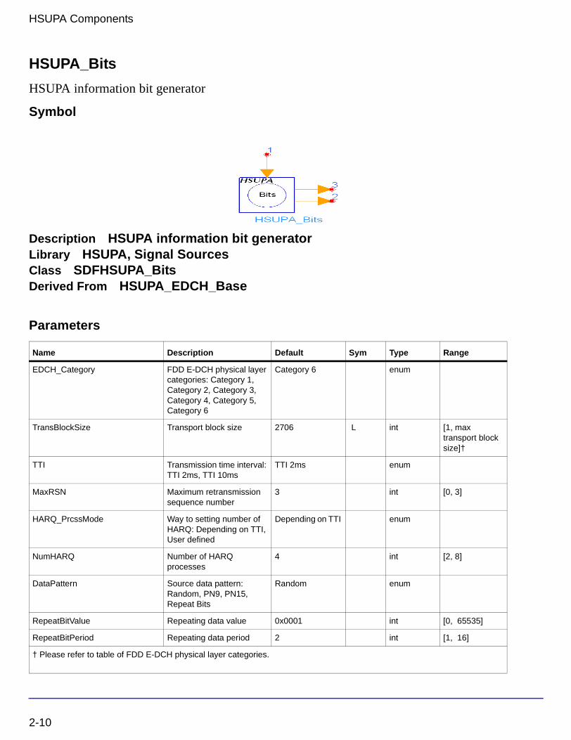
Description HSUPA information bit generatorLibrary HSUPA, Signal SourcesClass SDFHSUPA_BitsDerived From HSUPA_EDCH_Base
Parameters
Name Description Default Sym Type Range
EDCH_Category FDD E-DCH physical layer categories: Category 1, Category 2, Category 3, Category 4, Category 5, Category 6
Category 6 enum
TransBlockSize Transport block size 2706 L int [1, max transport block size]†
TTI Transmission time interval: TTI 2ms, TTI 10ms
TTI 2ms enum
MaxRSN Maximum retransmission sequence number
3 int [0, 3]
HARQ_PrcssMode Way to setting number of HARQ: Depending on TTI, User defined
Depending on TTI enum
NumHARQ Number of HARQ processes
4 int [2, 8]
DataPattern Source data pattern: Random, PN9, PN15, Repeat Bits
Random enum
RepeatBitValue Repeating data value 0x0001 int [0, 65535]
RepeatBitPeriod Repeating data period 2 int [1, 16]
† Please refer to table of FDD E-DCH physical layer categories.
2-10
Pin Inputs
Pin Outputs
Notes/Equations
1. This model is used to generate information bits packet by packet for use of HSUPA uplink transport channel. HARQ process is also implemented in this model.
Each firing, TransBlockSize Output tokens and one RSN token are generated when one ARQ token consumed. Note that ARQ pin is optional. When no output pin connected to it, no ARQ token is consumed.
2. The input value of ARQ is better to be in the range of but not limited to the set of 0 and 1. If the input of ARQ is 0, it means NACK and the correspondent packet is not received correctly. Otherwise, it means ACK and the correspondent packet is received correctly.
3. If ACK is received, UE will transmit new packet within current HARQ process. If NACK is received, UE will re-transmit the packet. The maximum re-transmission number is determined by parameter MaxRSN. if the re-transmission number is larger than MaxRSN, then this packet will be discarded and a new packet will be transmitted.
4. The delay for ARQ is fixed to NumHARQ * TTI. If HARQ_PrcssMode is set to Depending on TTI, NumHARQ is set to 8 for TTI 2ms and 4 for TTI 10 ms. Otherwise, the user can set the value of NumHARQ. For example, if 2ms TTI is used, UE will get the ARQ signal of the first packet when it send the ninth packet.
5. The output of RSN is the retransmission number of current packet. If it is a new packet, RSN is 0; if not, RSN can be 1, 2,..., MaxRSN incrementally.
6. For the DataPattern parameter:
• If Random is selected, random bits is generated.
• If PN9 is selected, a 511-bit pseudo-random test pattern is generated according to CCITT Recommendation O.153
Pin Name Description Signal Type
1 ARQ automatic repeat request int
Pin Name Description Signal Type
2 Output output int
3 RSN retransmission sequence number int
2-11

HSUPA Components
• If PN15 is selected, a 32767-bit pseudo-random test pattern is generated according to CCITT Recommendation O.151
• If Repeat Bits is selected, the data pattern depends on RepeatBitValue and RepeatBitPeriod. The RepeatBitPeriod length of LSB of RepeatBitValue will be repeated and filled in the data packet.
References
[1] 3GPP Technical Specification TS 25.211, "Physical channels and mapping of transport channels onto physical channels (FDD)," Version 6.7.0, Dec. 2005.
[2] 3GPP Technical Specification TS 25.212, "Multiplexing and channel coding (FDD)," Version 6.7.0, Dec. 2005.
[3] 3GPP Technical Specification TS 25.213, "Spreading and modulation (FDD)," Version 6.5.0, Mar. 2006.
[4] 3GPP Technical Specification TS 25.104, "UTRA (BS) FDD: Radio transmission and Reception," Version 6.12.0, Mar. 2006.
[5] 3GPP Technical Specification TS 25.141, "Base station conformance test," Version 6.13.0, Mar. 2006.
[6] CCITT, Recommendation O.151(10/92).
[7] CCITT, Recommendation O.153(10/92).
2-12

HSUPA_ChDecode
EDCH turbo decoder
Symbol
Description EDCH turbo decoderLibrary HSUPA, Demultiplexers & DecodersClass SDFHSUPA_ChDecodeDerived From HSUPA_EDCH_Base
Parameters
Pin Inputs
Name Description Default Sym Type Range
EDCH_Category FDD E-DCH physical layer categories: Category 1, Category 2, Category 3, Category 4, Category 5, Category 6
Category 6 enum
TransBlockSize Transport block size 2706 L int [1, max transport block size]†
TTI Transmission time interval: TTI 2ms, TTI 10ms
TTI 2ms enum
TC_Iteration Turbo code decoder iteration number
4 int [1, 10]
TC_Alfa Alfa of lowpass filter 0.4 real [0, 1.0)
† Please refer to table of FDD E-DCH physical layer categories.
Pin Name Description Signal Type
1 Input input real
2-13

HSUPA Components
Pin Outputs
Notes/Equations
1. This model is used to implement channel decoding in one code block for HSUPA uplink.
Each firing, (code block size) Output tokens are generated while (code block size * 3 + 12) Input tokens consumed.
A simple way to get the value of code block number, code block size and the number of padding bits and their relationship with the value of TransBlockSize is just to run the model HSUPA_CodeBlkSeg with wanted TransBlockSize in a minimal runnable design. The information will then be displayed in the simulation window.
2. A iterative Turbo MAP decoder using modified BAHL et al. algorithm [4][5] is used in this model. The iterative number can be set from 1 through to 10 through parameter TC_Iteration.
3. Alfa low-pass filter can be used to lower the variance of estimation of noise power, when noise power does not vary significantly block by block.
Pnoise = Pnoise × (1-α) + Pnoise_current_block × α
Where α can be set by parameter TC_Alfa.
References
[1] 3GPP Technical Specification TS 25.211, "Physical channels and mapping of transport channels onto physical channels (FDD)," Version 6.7.0, Dec. 2005.
[2] 3GPP Technical Specification TS 25.212, "Multiplexing and channel coding (FDD)," Version 6.7.0, Dec. 2005.
[3] 3GPP Technical Specification TS 25.213, "Spreading and modulation (FDD)," Version 6.5.0, Mar. 2006.
[4] L.R. Bahl, J. Cocke, F. Jeinek and J. Raviv. "Optimal decoding of linear codes for minimizing symbol error rate." IEEE Trans. Inform. Theory, vol. IT-20. pp.248-287, March 1974.
[5] C. Berrou and A. Glavieus. "Near optimum error correcting coding and decoding: turbo-codes", IEEE Trans. Comm., pp. 1261-1271, Oct. 1996.
Pin Name Description Signal Type
2 Output output int
2-14

HSUPA_ChEncode
EDCH turbo encoder
Symbol
Description EDCH turbo encoderLibrary HSUPA, Multiplexers & CodersClass SDFHSUPA_ChEncodeDerived From HSUPA_EDCH_Base
Parameters
Pin Inputs
Pin Outputs
Name Description Default Sym Type Range
EDCH_Category FDD E-DCH physical layer categories: Category 1, Category 2, Category 3, Category 4, Category 5, Category 6
Category 6 enum
TransBlockSize Transport block size 2706 L int [1, max transport block size]†
TTI Transmission time interval: TTI 2ms, TTI 10ms
TTI 2ms enum
† Please refer to table of FDD E-DCH physical layer categories.
Pin Name Description Signal Type
1 Input input int
Pin Name Description Signal Type
2 Output output int
2-15

HSUPA Components
Notes/Equations
1. This model is used to implement turbo code defined in 4.8.3 in [2] for HSUPA uplink.
Each firing, (code block size * 3 + 12) Output tokens are generated while (code block size) Input tokens consumed.
A simple way to get the value of the code block number, code block size and the number of padding bits and their relationship with the value of TransBlockSize is to run the model HSUPA_CodeBlkSeg with wanted TransBlockSize in a minimal runnable design. The information will then be displayed in the simulation window.
References
[1] 3GPP Technical Specification TS 25.211, "Physical channels and mapping of transport channels onto physical channels (FDD)," Version 6.7.0, Dec. 2005.
[2] 3GPP Technical Specification TS 25.212, "Multiplexing and channel coding (FDD)," Version 6.7.0, Dec. 2005.
[3] 3GPP Technical Specification TS 25.213, "Spreading and modulation (FDD)," Version 6.5.0, Mar. 2006.
2-16

HSUPA_CodeBlkDeseg
EDCH code block desegmentation
Symbol
Description EDCH code block desegmentationLibrary HSUPA, Demultiplexers & DecodersClass SDFHSUPA_CodeBlkDesegDerived From HSUPA_EDCH_Base
Parameters
Pin Inputs
Pin Outputs
Name Description Default Sym Type Range
EDCH_Category FDD E-DCH physical layer categories: Category 1, Category 2, Category 3, Category 4, Category 5, Category 6
Category 6 enum
TransBlockSize Transport block size 2706 L int [1, max transport block size]†
TTI Transmission time interval: TTI 2ms, TTI 10ms
TTI 2ms enum
† Please refer to table of FDD E-DCH physical layer categories.
Pin Name Description Signal Type
1 Input input int
Pin Name Description Signal Type
2 Output output int
2-17

HSUPA Components
Notes/Equations
1. This model is used to combine the decoded bits of each code block and recover the transport block.
2. This model implements the converse operation of HSUPA_CodeBlkSeg. For more information, see “HSUPA_CodeBlkSeg” on page 2-19.
References
[1] 3GPP Technical Specification TS 25.211, "Physical channels and mapping of transport channels onto physical channels (FDD)," Version 6.7.0, Dec. 2005.
[2] 3GPP Technical Specification TS 25.212, "Multiplexing and channel coding (FDD)," Version 6.7.0, Dec. 2005.
[3] 3GPP Technical Specification TS 25.213, "Spreading and modulation (FDD)," Version 6.5.0, Mar. 2006.
2-18

HSUPA_CodeBlkSeg
EDCH code block segmentation
Symbol
Description EDCH code block segmentationLibrary HSUPA, Multiplexers & CodersClass SDFHSUPA_CodeBlkSegDerived From HSUPA_EDCH_Base
Parameters
Pin Inputs
Pin Outputs
Name Description Default Sym Type Range
EDCH_Category FDD E-DCH physical layer categories: Category 1, Category 2, Category 3, Category 4, Category 5, Category 6
Category 6 enum
TransBlockSize Transport block size 2706 L int [1, max transport block size]†
TTI Transmission time interval: TTI 2ms, TTI 10ms
TTI 2ms enum
† Please refer to table of FDD E-DCH physical layer categories.
Pin Name Description Signal Type
1 Input input int
Pin Name Description Signal Type
2 Output output int
2-19

HSUPA Components
Notes/Equations
1. This model is used to segment uplink transport block into suitable size to fit the encoder.
Each firing, TransBlockSize+24 Input tokens are consumed. The Output tokens generated are generally the same as the Input tokens consumed. But padding bits may be appended depending on the algorithm described in 4.8.2 in [2].
If no padding bits are appended, the input and output of this model are the same.
A simple way to get the value of code block number, code block size and the number of padding bits and their relationship with the value of TransBlockSize is to run this model in a minimal runnable design. The information will then be displayed in the simulation window.
References
[1] 3GPP Technical Specification TS 25.211, "Physical channels and mapping of transport channels onto physical channels (FDD)," Version 6.7.0, Dec. 2005.
[2] 3GPP Technical Specification TS 25.212, "Multiplexing and channel coding (FDD)," Version 6.7.0, Dec. 2005.
[3] 3GPP Technical Specification TS 25.213, "Spreading and modulation (FDD)," Version 6.5.0, Mar. 2006.
2-20

HSUPA_Deinterleaver
EDCH deinterleaver
Symbol
Description EDCH deinterleaverLibrary HSUPA, Demultiplexers & DecodersClass SDFHSUPA_DeinterleaverDerived From HSUPA_EDCH_Base
Parameters
Pin Inputs
Name Description Default Sym Type Range
EDCH_Category FDD E-DCH physical layer categories: Category 1, Category 2, Category 3, Category 4, Category 5, Category 6
Category 6 enum
TransBlockSize Transport block size 2706 L int [1, max transport block size]†
TTI Transmission time interval: TTI 2ms, TTI 10ms
TTI 2ms enum
PuncLimit Puncturing limit for uplink 0.468 real [PLmax , 1]††
†Please refer to table of FDD E-DCH physical layer categories. ††PLmax is 0.33 for Category 6 and is 0.44 for all other categories.
Pin Name Description Signal Type
1 Input input real
2-21
HSUPA Components
Pin Outputs
Notes/Equations
1. This model is used to implement channel de-interleaving for HSUPA uplink. Function of this model is exactly converse of that of HSUPA_Interleaver. For more information, see “HSUPA_Interleaver” on page 2-90.
References
[1] 3GPP Technical Specification TS 25.211, "Physical channels and mapping of transport channels onto physical channels (FDD)," Version 6.7.0, Dec. 2005.
[2] 3GPP Technical Specification TS 25.212, "Multiplexing and channel coding (FDD)," Version 6.7.0, Dec. 2005.
[3] 3GPP Technical Specification TS 25.213, "Spreading and modulation (FDD)," Version 6.5.0, Mar. 2006.
Pin Name Description Signal Type
2 Output output real
2-22

HSUPA_DL_Rake
HSUPA downlink Rake receiver
Symbol
Description HSUPA downlink Rake receiverLibrary HSUPA, ReceiversClass SDFHSUPA_DL_RakeDerived From 3GPPHSUPA_DL_Rake
Parameters
Name Description Default Type Range
ScrambleCode index of scramble code 0 int [0, 512] for downlink; [0, 16777215] for uplink
ScrambleOffset scramble code offset 0 int [0, 15]
ScrambleType scramble code type: normal, right, left
normal enum
SampleRate sample rate 8 int [1, 256]
MaxDelaySample maximum delay boundary, in terms of samples
0 int [0, 2559] for RAKE receiver; [0, 102400] in other models
ChannelType select the channel type to be processed: CH_GAUSSIAN, CH_FADING
CH_GAUSSIAN enum
ChannelInfo fading channel information source: Known, Estimated
Known enum
ChannelInfoOffset offset between spread code and channel information in terms of sample
0 int [0, MaxDelaySample]
PathSearch path search frequency: EverySlot, Once
Once enum
2-23

HSUPA Components
Pin Inputs
Pin Outputs
SearchMethod path search method: Coherent, NonCoherent, Combined
Coherent enum
SearchSlotsNum number of slots for path search
1 int [1, 12]
PathNum number of Rake fingers 1 int [1, 6]
PathDelaySample delay for each finger, in terms of samples
0 int array [0, MaxDelaySample]; array size shall be equal to PathNum
EstSlotsNum Number of slots for channel estimation
1 int [1, 3]
EHI_ERG_SpreadCode Spreading code for E-HICH and E-RGCH
19 int [0, 127]
EAGCH_SpreadCode Spreading code for E-AGCH
100 int [0, 255]
RxEHICH_ERGCH Switch of EHICH and/or ERGCH demodulation: OFF, ON
ON enum
RxEAGCH Switch of EAGCH demodulation: OFF, ON
ON enum
† [0:5] for uplink DPCCH; [0:16] for downlink DPCH; [0:17] for downlink SCCPCH; [0:5] for uplink PCPCH (Ver 03_00); [0:2] for uplink PCPCH (Ver 12_00); [0:1] for uplink PCPCH (Ver 03_02).
Pin Name Description Signal Type
1 inChip input data stream complex
2 inChM input known channel information multiple complex
Pin Name Description Signal Type
3 HI_RG E-HICH or E-RGCH real
4 EAGCH_Sym absolute grant value index of E-AGCH real
5 symCPI symbols of CPICH real
6 outChM estimated channel information multiple complex
Name Description Default Type Range
2-24

Notes/Equations
1. This model is used to demodulate and despread 3GPP/HSUPA downlink signals (E-HICH, E-RGCH, and E-AGCH) with chip rate at 3.84 MHz. These signals may have multipath fading channel and additive Gaussian noise corruption.
2. To despread and demodulate a CDMA signal, the channel information and path delay information must be determined. Errors in channel estimation and path search deteriorate the receiver performance.
3. The signal processing flow inside the model is:
• Input data until slots specified by SearchSlotsNum are received
• Slot index identification
• SCH code index identification
• IQ offset correction, to eliminate any DC component
• Multipath search
• Channel estimate for each path
• Decoding and despreading of individual path
• Multipath combining
• Output decoded data to align at the slot boundary
• Output channel information (slots delayed are specified by SearchSlotsNum).
4. This model can be configured to work under ideal conditions; in other words, the real time channel information can be input from the input pin and the path delay information can be set by PathDelaySample. ChannelInfo determines if channel information is pin input or estimated inside the model. The delay for each path is expressed in terms of samples as individual elements in the array.
If path delay is known from the parameter, it is recommended to set the parameter SearchSlotsNum to 1, in order to save the simulation time.
5. If the first element in PathDelaySample is zero, the path searching is performed inside the receiver model. Otherwise, the numbers specified by PathDelaySample are taken as the delays for each path.
6. The path searching is performed by correlating the received signals with the spreading code specified in a window whose size is set by MaxDelaySample. The correlations at different offsets are ranked; the top ones are assumed to be the offsets where the paths could occur.
2-25

HSUPA Components
7. If SearchMethod = Coherent, correlation will be performed at the pilot bits only. If the SearchMethod = NonCoherent, correlation will be performed on the data field. Note that the coherent correlation obtained over pilot bits is unbiased, while the non-coherent correlation is biased. If SearchMethod = Combined, the coherent and non-coherent correlations are summed as the matrix for path resolution.
8. Another factor that impacts the correlation is the SearchSlotsNum parameter. This parameter sets the number of slots over which the correlation is accumulated. More slots are necessary for a reliable path resolution for signals with noise contamination. Usually, six slots are required if Eb/N0 is 2 dB. The user must determine the appropriate slot number and
search method for the best trade-off between accuracy and speed.
9. If the path delay is fixed, the path search is necessary only at the start of simulation. In this case, set PathSearch=Once to save simulation time. Otherwise, the path search will be performed for each slot received to update the dynamic path delay information.
10. Channel estimation varies according to channel type.
• If ChannelType = CH_GAUSSIAN, the channel is assumed to be time-invariant and the IQ phase shift is estimated using the pilot field of the signals received so far.
• If ChannelType = CH_FADING, channel characteristics are assumed to be time-variant and more complicated channel estimation must be used. A simple channel estimation is used that takes the fading characteristic averaged over the pilot field of the current slot as the channel information for the entire slot.
11. Generally the pilot in current slots is enough for channel estimation. But if Eb/N0 is very
low, while channel status varies relatively slowly, more slots are necessary for a reliable channel estimation. EstSlotsNum can be used to set number of slots used for channel estimation.
12. Channel information that is estimated on CPICH or known from input pins is output from pin outChM for reference. Each firing, 2560 tokens are produced as the channel information for the chips of the current demodulation slot.
Note If ChannelInfo = Estimated, CPICH must be included in the received signal for the Rake receiver to make the inside channel estimation.
13. All paths are combined assuming that all paths are useful for improving the decoding reliability. In some cases, paths with low SNR are actually harmful to the final SNR improvement. The user must set PathNum for better decoding performance in multipath conditions.
2-26

14. This model can be used to decode E-AGCH and E-HICH / E-RGCH. These channels are assumed to be time-aligned. If decoding of a specific channel is not necessary, it can be disabled by relative parameters to reduce simulation time.
15. Each firing, the number of input tokens is 2560 × SampleRate. There is a delay in terms of slots associated with the decoded information. The results are output after the number of firings equals SearchSlotsNum.
16. If the 3GPP/HSUPA signal is S(t), this signal may be delayed t1 by some filters (such as the Tx RC filters). So, the delayed signal is S(t-t1) and the signal from 0 to t1 is zero and the real 3GPP signal transmission starts from t1. When the delayed signals pass through a fading channel, the fading factor is applied to the overall signals starting from time 0. The offset t1 must be known if the receiver of the channel information is input from outside; this offset is expressed in terms of samples.
References
[1] 3GPP Technical Specification TS 25.211, "Physical channels and mapping of transport channels onto physical channels (FDD)," Version 6.7.0, Dec. 2005.
[2] 3GPP Technical Specification TS 25.212, "Multiplexing and channel coding (FDD)," Version 6.7.0, Dec. 2005.
[3] 3GPP Technical Specification TS 25.213, "Spreading and modulation (FDD)," Version 6.5.0, Mar. 2006.
2-27

HSUPA Components
HSUPA_DL_Receiver
HSUPA downlink receiver
Symbol
Description HSUPA downlink receiverLibrary HSUPA, ReceiversClass SDFHSUPA_DL_ReceiverDerived From HSUPA_SubcktBase
Parameters
Name Description Default Sym Type Range
TTI Transmission time interval: TTI 2ms, TTI 10ms
TTI 2ms enum
EHICH_SqnIdx Signature sequence index of EHICH
0 int [0, 39]
ERGCH_SqnIdx Signature sequence index of ERGCH
1 int [0, 39]
EHI_ERG_SpreadCode Spreading code for E-HICH and E-RGCH
19 int [0, 127]
EAGCH_SpreadCode Spreading code for E-AGCH
100 int [0, 255]
ERNTI E-DCH radio network temporary identifier
19 int [0, 65535]
ScrambleOffset Scramble code offset 0 int [0, 15]
ScrambleType Scramble code type: normal, right, left
normal enum
ScrambleCode Index of scramble code 0 int [0, 512] for downlink; [0, 16777215] for uplink
SamplesPerChip Samples per chip 8 S int [2, 32]
MaxDelaySample Maximum delay boundary, in terms of samples
0 int [0, 2559] for RAKE receiver; [0, 102400] in other models
2-28

Pin Inputs
Pin Outputs
ChannelType Select the channel type to be processed: CH_GAUSSIAN, CH_FADING
CH_GAUSSIAN enum
ChannelInfo Fading channel information source: Known, Estimated
Known enum
ChannelInfoOffset Offset between spread code and channel information in terms of sample
0 int [0, MaxDelaySample]
PathSearch Path search frequency: EverySlot, Once
Once enum
SearchMethod Path search method: Coherent, NonCoherent, Combined
Coherent enum
SearchSlotsNum Number of slots for path search
1 int [1, 12]
PathNum Number of Rake fingers 1 int [1, 6]
PathDelaySample Delay for each finger, in terms of samples
0 int array [0, MaxDelaySample]; array size shall be equal to PathNum
RxEHICH_ERGCH Switch of EHICH and/or ERGCH demodulation: OFF, ON
ON enum
RxEAGCH Switch of EAGCH demodulation: OFF, ON
ON enum
Threshold_EHICH Threshold for decoding E-HICH
-32 real (-∞, ∞)
Threshold_ERGCH Threshold for decoding E-RGCH
-20 real (-∞, ∞)
Pin Name Description Signal Type
1 Input input complex
2 CH_M channel information multiple complex
Pin Name Description Signal Type
3 EHICH E-HICH real
Name Description Default Sym Type Range
2-29

HSUPA Components
Notes/Equations
1. This subnetwork model is used to demodulate and decode HSUPA related downlink signals, i.e., E-DCH Absolute Grant Channel (E-AGCH), E-DCH Hybrid ARQ Indicator Channel (E-HICH), and E-DCH Relative Grant Channel (E-RGCH).
The schematic for this subnetwork is shown in Figure 2-1.
Figure 2-1. HSUPA_DL_Receiver Schematic
2. To despread and demodulate a CDMA signal, the channel information and path delay information must be determined. Errors in channel estimation and path search deteriorate the receiver performance.
3. This model can be configured to work under ideal conditions; in other words, the real time channel information can be input from input pin and the path delay information can be set by PathDelaySample. ChannelInfo determines if channel information is pin input or estimated inside the model. The delay for each path is expressed in terms of samples as individual elements in the array.
4 ERGCH E-RGCH real
5 EAGCH E-AGCH int
Pin Name Description Signal Type
2-30

If path delay is known from the parameter, it is recommended to set the parameter SearchSlotsNum to 1, in order to save the simulation time.
4. If the first element in PathDelaySample is zero, the path searching is performed inside the receiver model. Otherwise, the numbers specified by PathDelaySample are taken as the delays for each path.
5. The path searching is performed by correlating the received signals with the spreading code specified in a window whose size is set by MaxDelaySample. The correlations at different offsets are ranked; the top ones are assumed to be the offsets where the paths could occur.
6. If SearchMethod = Coherent, correlation will be performed at the pilot bits only. If the SearchMethod = NonCoherent, correlation will be performed on the data field. Note that the coherent correlation obtained over pilot bits is unbiased, while the non-coherent correlation is biased. If SearchMethod = Combined, the coherent and non-coherent correlations are summed as the matrix for path resolution.
7. Another factor that impacts the correlation is the SearchSlotsNum parameter. This parameter sets the number of slots over which the correlation is accumulated. More slots are necessary for a reliable path resolution for signals with noise contamination. Usually, 6 slots are required if Eb/No is 2 dB. The user must determine the appropriate slot number and search method for the best trade-off between accuracy and speed.
8. If the path delay is fixed, the path search is necessary only at the start of simulation. In this case, set PathSearch=Once to save simulation time. Otherwise, the path search will be performed for each slot received to update the dynamic path delay information.
9. Channel estimation varies according to channel type.
• If ChannelType = CH_GAUSSIAN, the channel is assumed to be time-invariant and the IQ phase shift is estimated using the pilot field of the signals received so far.
• If ChannelType = CH_FADING, channel characteristics are assumed to be time-variant and more complicated channel estimation must be used. A simple channel estimation is used that takes the fading characteristic averaged over the pilot field of the current slot as the channel information for the entire slot.
10. Channel information that is estimated on CPICH or known from input pins.
Note If ChannelInfo = Estimated, CPICH must be included in the received signal for the Rake receiver to make the inside channel estimation.
2-31

HSUPA Components
11. All paths are combined assuming that all paths are useful for improving the decoding reliability. In some cases, paths with low SNR are actually harmful to the final SNR improvement. The user must set PathNum for better decoding performance in multipath conditions.
12. This model can be used to decode E-AGCH and E-HICH / E-RGCH. These channels are assumed to be time-aligned. If decoding of a specific channel is not necessary, it can be disabled by relative parameters to reduce simulation time.
13. There is a delay in terms of slots associated with the decoded information, and it varies for different SearchSlotsNum and TTI combinations.
14. For more information regarding the Rake receiver and different channel decoders, please refer to the documents of HSUPA_DL_Rake, HSUPA_EAGCH_Decode, and HSUPA_EHICH_ERGCH_Decode respectively.
References
[1] 3GPP Technical Specification TS 25.211, "Physical channels and mapping of transport channels onto physical channels (FDD)," Version 6.7.0, Dec. 2005.
[2] 3GPP Technical Specification TS 25.212, "Multiplexing and channel coding (FDD)," Version 6.7.0, Dec. 2005.
[3] 3GPP Technical Specification TS 25.213, "Spreading and modulation (FDD)," Version 6.5.0, Mar. 2006.
2-32
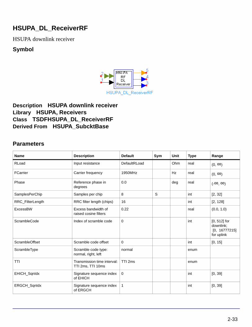
HSUPA_DL_ReceiverRF
HSUPA downlink receiver
Symbol
Description HSUPA downlink receiverLibrary HSUPA, ReceiversClass TSDFHSUPA_DL_ReceiverRFDerived From HSUPA_SubcktBase
Parameters
Name Description Default Sym Unit Type Range
RLoad Input resistance DefaultRLoad Ohm real (0, ∞)
FCarrier Carrier frequency 1950MHz Hz real (0, ∞)
Phase Reference phase in degrees
0.0 deg real (-∞, ∞)
SamplesPerChip Samples per chip 8 S int [2, 32]
RRC_FilterLength RRC filter length (chips) 16 int [2, 128]
ExcessBW Excess bandwidth of raised cosine filters
0.22 real (0.0, 1.0)
ScrambleCode Index of scramble code 0 int [0, 512] for downlink; [0, 16777215] for uplink
ScrambleOffset Scramble code offset 0 int [0, 15]
ScrambleType Scramble code type: normal, right, left
normal enum
TTI Transmission time interval: TTI 2ms, TTI 10ms
TTI 2ms enum
EHICH_SqnIdx Signature sequence index of EHICH
0 int [0, 39]
ERGCH_SqnIdx Signature sequence index of ERGCH
1 int [0, 39]
2-33

HSUPA Components
EHI_ERG_SpreadCode Spreading code for E-HICH and E-RGCH
19 int [0, 127]
EAGCH_SpreadCode Spreading code for E-AGCH
100 int [0, 255]
ERNTI E-DCH radio network temporary identifier
19 int [0, 65535]
MaxDelaySample Maximum delay boundary, in terms of samples
0 int [0, 2559] for RAKE receiver; [0, 102400] in other models
ChannelType Select the channel type to be processed: CH_GAUSSIAN, CH_FADING
CH_GAUSSIAN enum
ChannelInfo Fading channel information source: Known, Estimated
Known enum
ChannelInfoOffset Offset between spread code and channel information in terms of sample
0 int [0, MaxDelaySample]
PathSearch Path search frequency: EverySlot, Once
Once enum
SearchMethod Path search method: Coherent, NonCoherent, Combined
Coherent enum
SearchSlotsNum Number of slots for path search
1 int [1, 12]
PathNum Number of Rake fingers 1 int [1, 6]
PathDelaySample Delay for each finger, in terms of samples
0 int array [0, MaxDelaySample]; array size shall be equal to PathNum
RxEHICH_ERGCH Switch of EHICH and/or ERGCH demodulation: OFF, ON
ON enum
RxEAGCH Switch of EAGCH demodulation: OFF, ON
ON enum
Threshold_EHICH Threshold for decoding E-HICH
-32 real (-∞, ∞)
Threshold_ERGCH Threshold for decoding E-RGCH
-20 real (-∞, ∞)
Name Description Default Sym Unit Type Range
2-34

Pin Inputs
Pin Outputs
Notes/Equations
1. This subnetwork model is used to demodulate and decode HSUPA related downlink RF signals, i.e., E-DCH Absolute Grant Channel (E-AGCH), E-DCH Hybrid ARQ Indicator Channel (E-HICH), and E-DCH Relative Grant Channel (E-RGCH).
The schematic for this subnetwork is shown in Figure 2-2.
Figure 2-2. HSUPA_DL_ReceiverRF Schematic
2. To despread and demodulate a CDMA signal, the channel information and path delay information must be determined. Errors in channel estimation and path search deteriorate the receiver performance.
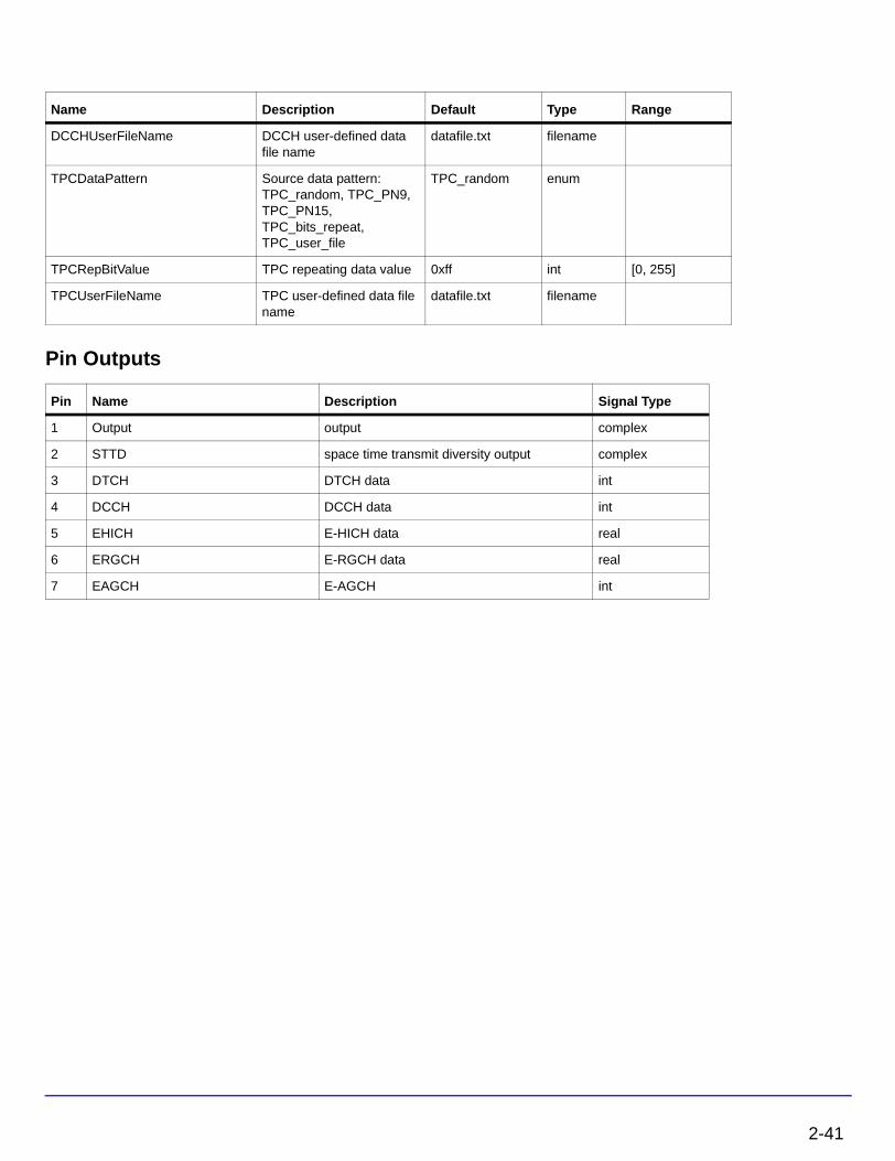
Pin Name Description Signal Type
1 RF input timed
2 CH_M channel information multiple complex
Pin Name Description Signal Type
3 EHICH E-HICH real
4 ERGCH E-RGCH real
5 EAGCH E-AGCH int
2-35

HSUPA Components
3. This model can be configured to work under ideal conditions; in other words, the real time channel information can be input from input pin and the path delay information can be set by PathDelaySample. ChannelInfo determines if channel information is pin input or estimated inside the model. The delay for each path is expressed in terms of samples as individual elements in the array.
If path delay is known from the parameter, it is recommended to set the parameter SearchSlotsNum to 1, in order to save the simulation time.
4. If the first element in PathDelaySample is zero, the path searching is performed inside the receiver model. Otherwise, the numbers specified by PathDelaySample are taken as the delays for each path.
5. The path searching is performed by correlating the received signals with the spreading code specified in a window whose size is set by MaxDelaySample. The correlations at different offsets are ranked; the top ones are assumed to be the offsets where the paths could occur.
6. If SearchMethod = Coherent, correlation will be performed at the pilot bits only. If the SearchMethod = NonCoherent, correlation will be performed on the data field. Note that the coherent correlation obtained over pilot bits is unbiased, while the non-coherent correlation is biased. If SearchMethod = Combined, the coherent and non-coherent correlations are summed as the matrix for path resolution.
7. Another factor that impacts the correlation is the SearchSlotsNum parameter. This parameter sets the number of slots over which the correlation is accumulated. More slots are necessary for a reliable path resolution for signals with noise contamination. Usually, six slots are required if Eb/N0 is 2 dB. The user must determine the appropriate slot number and
search method for the best trade-off between accuracy and speed.
8. If the path delay is fixed, the path search is necessary only at the start of simulation. In this case, set PathSearch=Once to save simulation time. Otherwise, the path search will be performed for each slot received to update the dynamic path delay information.
9. Channel estimation varies according to channel type.
• If ChannelType = CH_GAUSSIAN, the channel is assumed to be time-invariant and the IQ phase shift is estimated using the pilot field of the signals received so far.
• If ChannelType = CH_FADING, channel characteristics are assumed to be time-variant and more complicated channel estimation must be used. A simple channel estimation is used that takes the fading characteristic averaged over the pilot field of the current slot as the channel information for the entire slot.
2-36

10. Channel information that is estimated on CPICH or known from input pins.
Note If ChannelInfo = Estimated, CPICH must be included in the received signal for the Rake receiver to make the inside channel estimation.
11. All paths are combined assuming that all paths are useful for improving the decoding reliability. In some cases, paths with low SNR are actually harmful to the final SNR improvement. The user must set PathNum for better decoding performance in multipath conditions.
12. This model can be used to decode E-AGCH and E-HICH / E-RGCH. These channels are assumed to be time-aligned. If decoding of a specific channel is not necessary, it can be disabled by relative parameters to reduce simulation time.
13. There is a delay in terms of slots associated with the decoded information, and it varies for different SearchSlotsNum and TTI combinations.
14. For more information regarding the Rake receiver and different channel decoders, please see “HSUPA_DL_Rake” on page 2-23, “HSUPA_EAGCH_Decode” on page 2-58, and “HSUPA_EHICH_ERGCH_Decode” on page 2-70.
References
[1] 3GPP Technical Specification TS 25.211, "Physical channels and mapping of transport channels onto physical channels (FDD)," Version 6.7.0, Dec. 2005.
[2] 3GPP Technical Specification TS 25.212, "Multiplexing and channel coding (FDD)," Version 6.7.0, Dec. 2005.
[3] 3GPP Technical Specification TS 25.213, "Spreading and modulation (FDD)," Version 6.5.0, Mar. 2006.
[4] 3GPP Technical Specification TS 25.214, "Physical layer procedures (FDD)," Version 6.8.0, Mar. 2006.
[5] 3GPP Technical Specification TS 25.101, "UE Radio transmission and Reception (FDD)," Version 6.11.0, Mar. 2006.
2-37

HSUPA Components
HSUPA_DL_Source
HSUPA downlink source
Symbol
Description HSUPA downlink sourceLibrary HSUPA, Signal SourcesClass SDFHSUPA_DL_SourceDerived From HSUPA_SubcktBase
Parameters
Name Description Default Type Range
TTI Transmission time interval: TTI 2ms, TTI 10ms
TTI 2ms enum
EHICH_SgnlPttrn E-HICH signal pattern 1.0 int array [-1, +1]
ERGCH_SgnlPttrn E-RGCH signal pattern 1.0 int array [-1, +1]
EHICH_SqnIdx Signature sequence index of EHICH
0 int [0, 39]
ERGCH_SqnIdx Signature sequence index of ERGCH
1 int [0, 39]
EHI_ERG_SpreadCode Spreading code for E-HICH and E-RGCH
19 int [0, 127]
EAGCH_SpreadCode Spreading code for E-AGCH
100 int [0, 255]
ERNTI E-DCH radio network temporary identifier
19 int [0, 65535]
EHICH_GainFactor EHICH power gain in dB 1.0 real (-∞, ∞)
ERGCH_GainFactor ERGCH power gain in dB 1.0 real (-∞, ∞)
EAGCH_GainFactor EAGCH power gain in dB 1.0 real (-∞, ∞)
ScrambleOffset Scramble code offset 0 int [0, 15]
ScrambleType Scramble code type: normal, right, left
normal enum
2-38

ScrambleCode Index of scramble code 0 int [0, 512] for downlink; [0, 16777215] for uplink
RefCh Reference measurement channel: DL_REF_12_2, DL_REF_64, DL_REF_144, DL_REF_384
DL_REF_12_2 enum
DPCH_SpreadCode Spread code index of DPCH
127 int [0, 127] for 12.2kbps; [0, 31] for 64kbps; [0, 15] for 144kbps; [0, 7] for 384kbps
CPICH_SpreadCode Spread code index of CPICH
2 int [0, 255]
PICH_SpreadCode Spread code index of PICH 16 int [0, 255]
SCCPCH_SlotFormat SCCPCH slot format 0 int [0, 17]
SCCPCH_SpreadCode Spread code index of SCCPCH
3 int [0, SpreadFactor-1]; SpreadFactor is set by SCCPCH_SlotFormat
DPCH_GainFactor DPCH Ec over Ior in dB, valid only if PowerReference is Ior
1.0 real (-∞, ∞)
P_CPICH_GainFactor Primary CPICH power gain in dB
1.0 real (-∞, ∞)
S_CPICH_GainFactor Secondary CPICH power gain in dB
1.0 real (-∞, ∞)
PCCPCH_GainFactor PCCPCH power gain in dB 1.0 real (-∞, ∞)
SCCPCH_GainFactor SCCPCH power gain in dB 1.0 real (-∞, ∞)
P_SCH_GainFactor Primary SCH power gain in dB
1.0 real (-∞, ∞)
S_SCH_GainFactor Secondary SCH power gain in dB
1.0 real (-∞, ∞)
PICH_GainFactor PICH power gain in dB 1.0 real (-∞, ∞)
OCNS_GainFactor OCNS gain in dB, valid only if PowerReference is DPCH_Ec
1.0 real (-∞, ∞)
OCNS_ChannelNum OCNS channel number 16 int [1, 512]
Name Description Default Type Range
2-39

HSUPA Components
OCNS_PowerArray OCNS channel power array in dB
-1 -3 -3 -5 -2 -4 -8 -7 -4 -6 -5 -9 -10 -8 -6 0
real array (-∞, ∞); the array size shall be equal to OCNS_ChannelNum
OCNS_SpreadFactorArray OCNS spread factor array 128 128 128 128 128 128 128 128 128 128 128 128 128 128 128 128
int array 2n , n=1,...,9; array size shall be equal to OCNS_ChannelNum
OCNS_SpreadCodeArray OCNS spread code array 2 11 17 23 31 38 47 55 62 69 78 85 94 125 113 119
int array [0, OCNS_SpreadFactorArray-1]; array size shall be equal to OCNS_ChannelNum; code conflict is checked
OCNS_DataPatternArray OCNS data pattern array: 0-random, 1-PN9, 2-PN15, 3-Repeat Bits
0 0 0 0 0 0 0 0 0 0 0 0 0 0 0 0
int array [0, 1,2,3]; array size shall be equal to OCNS_ChannelNum
OCNS_RepBitValueArray OCNS repeat bit value array
0 0 0 0 0 0 0 0 0 0 0 0 0 0 0 0
int array [0, 255]; array size shall be equal to OCNS_ChannelNum
OCNS_tOffsetArray OCNS time offset in terms of 256 chips
0 0 0 0 0 0 0 0 0 0 0 0 0 0 0 0
int array [0, 149]; array size shall be equal to OCNS_ChannelNum
DTCHDataPattern DTCH source data pattern: DTCH_random, DTCH_PN9, DTCH_PN15, DTCH_bits_repeat, DTCH_user_file
DTCH_random enum
DTCHRepBitValue DTCH repeating data value 0xff int [0, 255]
DTCHUserFileName DTCH user-defined data file name
datafile.txt filename
DCCHDataPattern DCCH source data pattern: DCCH_random, DCCH_PN9, DCCH_PN15, DCCH_bits_repeat, DCCH_user_file
DCCH_random enum
DCCHRepBitValue DCCH repeating data value
0xff int [0, 255]
Name Description Default Type Range
2-40
Pin Outputs
DCCHUserFileName DCCH user-defined data file name
datafile.txt filename
TPCDataPattern Source data pattern: TPC_random, TPC_PN9, TPC_PN15, TPC_bits_repeat, TPC_user_file
TPC_random enum
TPCRepBitValue TPC repeating data value 0xff int [0, 255]
TPCUserFileName TPC user-defined data file name
datafile.txt filename
Pin Name Description Signal Type
1 Output output complex
2 STTD space time transmit diversity output complex
3 DTCH DTCH data int
4 DCCH DCCH data int
5 EHICH E-HICH data real
6 ERGCH E-RGCH data real
7 EAGCH E-AGCH int
Name Description Default Type Range
2-41

HSUPA Components
Notes/Equations
1. This subnetwork model is used to simulate integrated base station signal source.
The schematic for this subnetwork is shown in Figure 2-3.
Figure 2-3. HSUPA_DL_Source Schematic
2. The physical channels integrated in this subnetwork model are listed in Table 2-3.
Table 2-3. Downlink Physical Channels
Physical Channel
P_CPICH
S_CPICH
PCCPCH
P_SCH
S_SCH
2-42

3. The DPCH is generated by the fully-coded 3GPPFDD_DL_RefCh signal source.
4. DTCH, DCCH, and TPC patterns can be set through the DTCHDataPattern, DCCHDataPattern, and TPCDataPattern parameters; Five data patterns are supported: random, PN9, PN15, fixed repeated 8-bits, and user-defined file.
5. If the data pattern is 8-bits repeating, the bits to be repeated are set by the respective RepBitValue. For example if RepBitValue is set as 0x7a, bit sequence 0,1,1,1,1,0,1,0 will be output repeatedly.
6. If data is from a user-defined file, the file name is defined by the respective UserFileName. The user can edit the file with any text editor. The separator between bits can be a space, comma, or any other separator. If the bit sequence is shorter than the output length, data will be output repeatedly.
7. The DPCH data rate can be set through RefCh. DPCH channelization code is set through DPCH_SpreadCode.
8. CPICH includes primary and secondary CPICH. Primary CPICH channelization code is fixed at C256,0. CPICH_SpreadCode is set on secondary CPICH, with a spread factor of 256.
9. The PICH spread factor is 256. PICH channelization code is set through PICH_SpreadCode.
10. The PCCPCH channelization code is fixed at C256,1. The SCCPCH spread factor and spread channelization code are set through SCCPCH_SpreadFactor and SCCPCH_SpreadCode.
11. The E-HICH can be set by EHICH_SgnlPttrn (Signal Pattern), EHICH_SqnIdx (Signature Sequence Index), and EHI_ERG_SpreadCode.
12. The E-RGCH can be set by ERGCH_SgnlPttrn (Signal Pattern), ERGCH_SqnIdx (Signature Sequence Index), and EHI_ERG_SpreadCode.
SCCPCH
PICH
DPCH
E-AGCH
E-HICH
E-RGCH
OCNS
Table 2-3. Downlink Physical Channels
Physical Channel
2-43

HSUPA Components
13. The E-AGCH can be set by EAGCH_SpreadCode and ERNTI.
14. Relative gain factor of each channel can be set through the respective GainFactor parameters. They are multiplied to the output of each channel model. A channel can be disabled by setting its gain factor to 0.
15. It is suggested that the square of all the GainFactors add up to 1 to make sure the RMS value of output downlink signal is 1. However, it isn’t so important for the baseband signal. A normalized downlink source can be implemented by HSUPA_DL_SourceRF.
16. OCNS can be set through the OCNS_ChannelNum and six OCNS array parameters. The default OCNS channel is 16 and corresponding array parameters are 16 elements long. To change the OCNS channel number, the corresponding array parameters must be changed. For details regarding OCNS settings, see “HSUPA_OCNS” on page 2-92.
References
[1] 3GPP Technical Specification TS 25.211, "Physical channels and mapping of transport channels onto physical channels (FDD)," Version 6.7.0, Dec. 2005.
[2] 3GPP Technical Specification TS 25.212, "Multiplexing and channel coding (FDD)," Version 6.7.0, Dec. 2005.
[3] 3GPP Technical Specification TS 25.213, "Spreading and modulation (FDD)," Version 6.5.0, Mar. 2006.
2-44

HSUPA_DL_SourceRF
HSUPA downlink signal source
Symbol
Description HSUPA RF downlink signal sourceLibrary HSUPA, Signal SourcesClass TSDFHSUPA_DL_SourceRFDerived From HSUPA_SubcktBase
Parameters
Name Description Default Sym Unit Type Range
ROut Source resistance DefaultROut Ohm real (0, ∞)
RTemp Temperature DefaultRTemp Celsius real [-273.15, ∞)
TStep Expression showing how TStep is related to the other source parameters
1/3.84 MHz/SamplesPerChip
string
FCarrier Carrier frequency 1950MHz Hz real (0, ∞)
Power Power, valid only if PowerReference setting is Ior
dbmtow(43.0) W real [0, ∞)
PowerReference Reference for all channels with relative power level: Ior, DPCH__Ec
Ior enum
DPCH_Ec Ec of DPCH in dBm/3.84 MHz
-100 dB real (-∞, ∞)
MirrorSpectrum Mirror spectrum about carrier? NO, YES
NO enum
GainImbalance Gain imbalance, Q vs I 0.0 dB real (-∞, ∞)
PhaseImbalance Phase imbalance, Q vs I 0.0 deg real (-∞, ∞)
I_OriginOffset I origin offset (percent) 0.0 real (-∞, ∞)
Q_OriginOffset Q origin offset (percent) 0.0 real (-∞, ∞)
2-45

HSUPA Components
IQ_Rotation IQ rotation 0.0 deg real (-∞, ∞)
SamplesPerChip Samples per chip 8 S int [2, 32]
RRC_FilterLength RRC filter length (chips) 16 int [2, 128]
ExcessBW Excess bandwidth of raised cosine filters
0.22 real (0.0, 1.0)
ScrambleCode Index of scramble code 0 int [0, 512] for downlink; [0, 16777215] for uplink
ScrambleOffset Scramble code offset 0 int [0, 15]
ScrambleType Scramble code type: normal, right, left
normal enum
TTI Transmission time interval: TTI 2ms, TTI 10ms
TTI 2ms enum
EHICH_SgnlPttrn E-HICH signal pattern 1.0 int array [-1, +1]
ERGCH_SgnlPttrn E-RGCH signal pattern 1.0 int array [-1, +1]
EHICH_SqnIdx Signature sequence index of EHICH
0 int [0, 39]
ERGCH_SqnIdx Signature sequence index of ERGCH
1 int [0, 39]
EHI_ERG_SpreadCode Spreading code for E-HICH and E-RGCH
19 int [0, 127]
EAGCH_SpreadCode Spreading code for E-AGCH
100 int [0, 255]
ERNTI E-DCH radio network temporary identifier
19 int [0, 65535]
EHICH_GainFactor EHICH power gain in dB -28.3 dB real (-∞, ∞)
ERGCH_GainFactor ERGCH power gain in dB -24.4 dB real (-∞, ∞)
EAGCH_GainFactor EAGCH power gain in dB -23.2 dB real (-∞, ∞)
RefCh Reference measurement channel: DL_REF_12_2, DL_REF_64, DL_REF_144, DL_REF_384
DL_REF_12_2 enum
DPCH_SpreadCode Spread code index of DPCH
127 int [0, 127] for 12.2kbps; [0, 31] for 64kbps; [0, 15] for 144kbps; [0, 7] for 384kbps
CPICH_SpreadCode Spread code index of CPICH
2 int [0, 255]
Name Description Default Sym Unit Type Range
2-46

PICH_SpreadCode Spread code index of PICH 16 int [0, 255]
SCCPCH_SlotFormat SCCPCH slot format 0 int [0, 17]
SCCPCH_SpreadCode Spread code index of SCCPCH
3 int [0, SpreadFactor-1]; SpreadFactor is set by SCCPCH_SlotFormat
DPCH_GainFactor DPCH Ec over Ior in dB, valid only if PowerReference is Ior
-15 dB real (-∞, ∞)
P_CPICH_GainFactor Primary CPICH power gain in dB
-10.0 dB real (-∞, ∞)
S_CPICH_GainFactor Secondary CPICH power gain in dB
-300.0 dB real (-∞, ∞)
PCCPCH_GainFactor PCCPCH power gain in dB -12 dB real (-∞, ∞)
SCCPCH_GainFactor SCCPCH power gain in dB -300 dB real (-∞, ∞)
P_SCH_GainFactor Primary SCH power gain in dB
-15 dB real (-∞, ∞)
S_SCH_GainFactor Secondary SCH power gain in dB
-15 dB real (-∞, ∞)
PICH_GainFactor PICH power gain in dB -15 dB real (-∞, ∞)
OCNS_GainFactor OCNS gain in dB, valid only if PowerReference is DPCH_Ec
-300 dB real (-∞, ∞)
OCNS_ChannelNum OCNS channel number 16 int [1, 512]
OCNS_PowerArray OCNS channel power array in dB
-1 -3 -3 -5 -2 -4 -8 -7 -4 -6 -5 -9 -10 -8 -6 0
real array (-∞, ∞); the array size shall be equal to OCNS_ChannelNum
OCNS_SpreadFactorArray OCNS spread factor array 128 128 128 128 128 128 128 128 128 128 128 128 128 128 128 128
int array 2n , n=1,...,9; array size shall be equal to OCNS_ChannelNum
OCNS_SpreadCodeArray OCNS spread code array 2 11 17 23 31 38 47 55 62 69 78 85 94 125 113 119
int array [0, OCNS_SpreadFactorArray-1]; array size shall be equal to OCNS_ChannelNum; code conflict is checked
Name Description Default Sym Unit Type Range
2-47
HSUPA Components
Pin Outputs
OCNS_DataPatternArray OCNS data pattern array: 0-random, 1-PN9, 2-PN15, 3-Repeat Bits
0 0 0 0 0 0 0 0 0 0 0 0 0 0 0 0
int array [0, 1,2,3]; array size shall be equal to OCNS_ChannelNum
OCNS_RepBitValueArray OCNS repeat bit value array
0 0 0 0 0 0 0 0 0 0 0 0 0 0 0 0
int array [0, 255]; array size shall be equal to OCNS_ChannelNum
OCNS_tOffsetArray OCNS time offset in terms of 256 chips
0 0 0 0 0 0 0 0 0 0 0 0 0 0 0 0
int array [0, 149]; array size shall be equal to OCNS_ChannelNum
DTCHDataPattern DTCH source data pattern: DTCH_random, DTCH_PN9, DTCH_PN15, DTCH_bits_repeat, DTCH_user_file
DTCH_random enum
DTCHRepBitValue DTCH repeating data value 0xff int [0, 255]
DTCHUserFileName DTCH user-defined data file name
datafile.txt filename
DCCHDataPattern DCCH source data pattern: DCCH_random, DCCH_PN9, DCCH_PN15, DCCH_bits_repeat, DCCH_user_file
DCCH_random enum
DCCHRepBitValue DCCH repeating data value
0xff int [0, 255]
DCCHUserFileName DCCH user-defined data file name
datafile.txt filename
TPCDataPattern Source data pattern: TPC_random, TPC_PN9, TPC_PN15, TPC_bits_repeat, TPC_user_file
TPC_random enum
TPCRepBitValue TPC repeating data value 0xff int [0, 255]
TPCUserFileName TPC user-defined data file name
datafile.txt filename
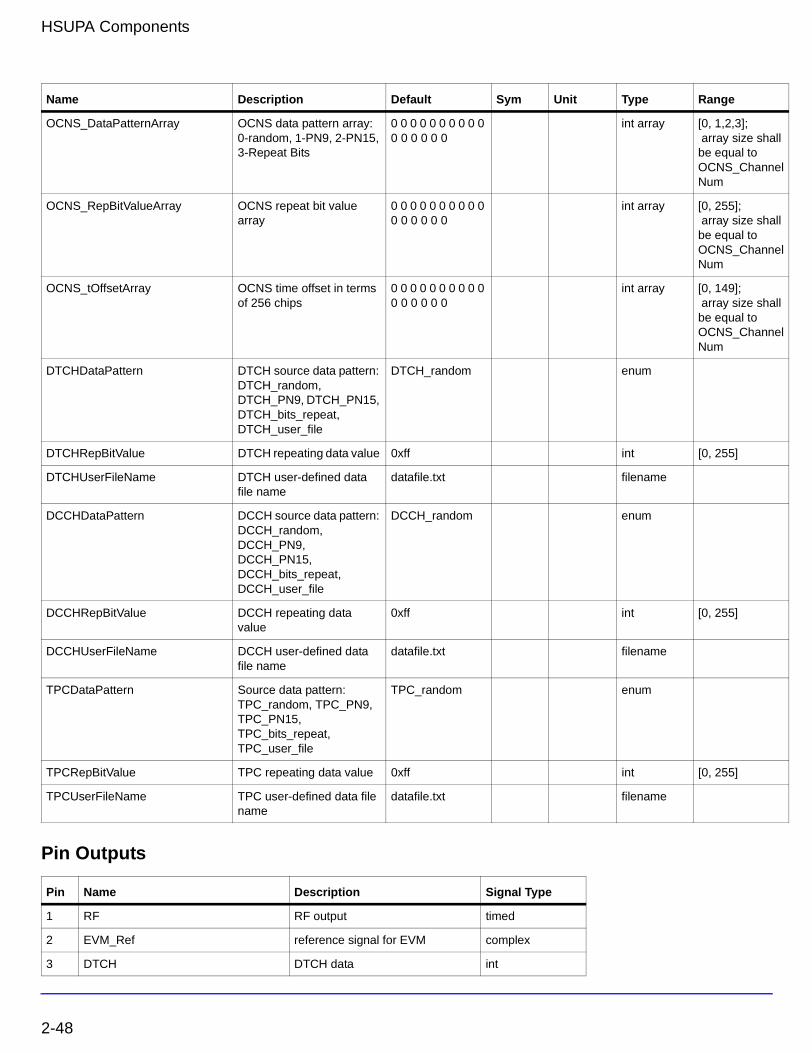
Pin Name Description Signal Type
1 RF RF output timed
2 EVM_Ref reference signal for EVM complex
3 DTCH DTCH data int
Name Description Default Sym Unit Type Range
2-48

4 DCCH DCCH data int
5 EHICH E-HICH data real
6 ERGCH E-RGCH data real
7 EAGCH E-AGCH int
Pin Name Description Signal Type
2-49

HSUPA Components
Notes/Equations
1. This subnetwork model is used to simulate integrated base station RF signal source.
The schematic for this subnetwork is shown in Figure 2-4.
Figure 2-4. HSUPA_DL_SourceRF Schematic
2-50

2. The physical channels integrated in this subnetwork model are listed in Table 2-4.
3. The DPCH is generated by the fully-coded 3GPPFDD_DL_RefCh signal source.
4. DTCH, DCCH, and TPC patterns can be set through the DTCHDataPattern, DCCHDataPattern, and TPCDataPattern parameters; five data patterns are supported: random, PN9, PN15, fixed repeated 8-bits, and user-defined file.
5. If the data pattern is 8-bits repeating, the bits to be repeated are set by the respective RepBitValue. For example if RepBitValue is set as 0x7a, bit sequence 0,1,1,1,1,0,1,0 will be output repeatedly.
6. If data is from a user-defined file, the file name is defined by the respective UserFileName. The user can edit the file with any text editor. The separator between bits can be a space, comma, or any other separator. If the bit sequence is shorter than the output length, data will be output repeatedly.
7. The DPCH data rate can be set through RefCh. DPCH channelization code is set through DPCH_SpreadCode.
8. CPICH includes primary and secondary CPICH. Primary CPICH channelization code is fixed at C256,0. CPICH_SpreadCode is set on secondary CPICH, with a spread factor of 256.
9. The PICH spread factor is 256. PICH channelization code is set through PICH_SpreadCode.
Table 2-4. Downlink Physical Channels
Physical Channel
P_CPICH
S_CPICH
PCCPCH
P_SCH
S_SCH
SCCPCH
PICH
DPCH
E-AGCH
E-HICH
E-RGCH
OCNS
2-51

HSUPA Components
10. The PCCPCH channelization code is fixed at C256,1. The SCCPCH spread factor and spread channelization code are set through SCCPCH_SpreadFactor and SCCPCH_SpreadCode.
11. The E-HICH can be set by EHICH_SgnlPttrn (Signal Pattern), EHICH_SqnIdx (Signature Sequence Index), and EHI_ERG_SpreadCode.
12. The E-RGCH can be set by ERGCH_SgnlPttrn (Signal Pattern), ERGCH_SqnIdx (Signature Sequence Index), and EHI_ERG_SpreadCode.
13. The E-AGCH can be set by EAGCH_SpreadCode and ERNTI.
14. There are two ways to set the power ratio defined in Table C.2 and Table C.3 in [5]. Although each of these two ways can be converted to the other by calculation, the parameter PowerReference is provided for the user to set the power easily.
If PowerReference is Ior, the power of transmitter is set by parameter Power; if it is DPCH_Ec, the power of transmitter depends on the value of parameter DPCH_Ec and is calculated in the equations of the subnetwork.
Relative power levels of each channel can then be set through the respective GainFactor parameters, in dB units.
• If PowerReference is Ior, OCNS_GainFactor is calculated from other GainFactors. (Refer to Table C.6 in [5]);
If PowerReference is DPCH_Ec, the relative Ior is calculated.
DPCH_GainFactor is equal to the inverse of Ior.
All “GainFactors” are changed to power ratio over Ior by multiplying DPCH_GainFactor.
The GainFactors are converted into voltage values and multiplied to the output of each channel model. A channel can be disabled by setting its gain factor to a large minus value such as -300 dB.
15. OCNS can be set through the OCNS_ChannelNum and six OCNS array parameters. The default OCNS channel is 16 and corresponding array parameters are 16 elements long. To change the OCNS channel number, the corresponding array parameters must be changed. The output of OCNS must be normalized. For details regarding OCNS settings, see “HSUPA_OCNS” on page 2-92.
2-52

References
[1] 3GPP Technical Specification TS 25.211, "Physical channels and mapping of transport channels onto physical channels (FDD)," Version 6.7.0, Dec. 2005.
[2] 3GPP Technical Specification TS 25.212, "Multiplexing and channel coding (FDD)," Version 6.7.0, Dec. 2005.
[3] 3GPP Technical Specification TS 25.213, "Spreading and modulation (FDD)," Version 6.5.0, Mar. 2006.
[4] 3GPP Technical Specification TS 25.214, "Physical layer procedures (FDD)," Version 6.8.0, Mar. 2006.
[5] 3GPP Technical Specification TS 25.101, "UE Radio transmission and Reception (FDD)," Version 6.11.0, Mar. 2006.
2-53

HSUPA Components
HSUPA_EAGCH
E-DCH absolute grant channel
Symbol
Description E-DCH absolute grant channelLibrary HSUPA, Signal SourcesClass SDFHSUPA_EAGCHDerived From HSUPA_SubcktBase
Parameters
Pin Inputs
Name Description Default Type Range
TTI Transmission time interval: TTI 2ms, TTI 10ms
TTI 2ms enum
EAGCH_SpreadCode Spreading code for E-AGCH
100 int [0, 255]
ERNTI E-DCH radio network temporary identifier
19 int [0, 65535]
ScrambleOffset Scramble code offset 0 int [0, 15]
ScrambleType Scramble code type: normal, right, left
normal enum
ScrambleCode Index of scramble code 0 int [0, 512] for downlink; [0, 16777215] for uplink
Pin Name Description Signal Type
1 ValueIdx absolute grant value index int
2 Scope absolute grant scope int
2-54

Pin Outputs
Notes/Equations
1. This subnetwork model is used to generate the 3GPP/HSUPA absolute grant channel (E-AGCH) as defined in [2], Figure 24: “Coding for E-AGCH”.
The schematic for this subnetwork is shown in Figure 2-5.
Pin Name Description Signal Type
3 Output output complex
4 STTD space time transmit diversity output complex
5 EAGCH E-AGCH int
2-55

HSUPA Components
Figure 2-5. HSUPA_EAGCH Schematic
2-56

2. This subnetwork model completes the following operations:
• Multiplexing of E-AGCH information: Absolute Grant Value and Absolute Grant Scope
• CRC attachment for E-AGCH (including E-RNTI mask)
• Channel coding for E-AGCH
• Rate matching for E-AGCH
• Physical channel mapping for E-AGCH.
References
[1] 3GPP Technical Specification TS 25.211, "Physical channels and mapping of transport channels onto physical channels (FDD)," Version 6.7.0, Dec. 2005.
[2] 3GPP Technical Specification TS 25.212, "Multiplexing and channel coding (FDD)," Version 6.7.0, Dec. 2005.
[3] 3GPP Technical Specification TS 25.213, "Spreading and modulation (FDD)," Version 6.5.0, Mar. 2006.
2-57

HSUPA Components
HSUPA_EAGCH_Decode
Channel decoder of E-DCH absolute grant channel
Symbol
Description Channel decoder of E-DCH absolute grant channelLibrary HSUPA, Demultiplexers & DecodersClass SDFHSUPA_EAGCH_DecodeDerived From HSUPA_SubcktBase
Parameters
Pin Inputs
Pin Outputs
Name Description Default Type Range
TTI Transmission time interval: TTI 2ms, TTI 10ms
TTI 2ms enum
ERNTI E-DCH radio network temporary identifier
19 int [0, 65535]
Pin Name Description Signal Type
1 AG_Sym input symbols real
Pin Name Description Signal Type
2 EAGCH Information bits for H-AGCH int
3 Parity The result of CRC int
4 ValueIdx absolute grant value index int
5 Scope absolute grant scope int
2-58

Notes/Equations
1. This subnetwork model completes the inverse process of “Coding for E-AGCH”, which is defined in [2], Figure 24.
The schematic for this subnetwork is shown in Figure 2-6.
Figure 2-6. HSUPA_EAGCH_Decode Schematic
2. This subnetwork model completes the following operations:
• Rate de-matching for E-AGCH
• Viterbi decoding for E-AGCH
• CRC checking for E-AGCH
• De-multiplexing of E-AGCH information: Absolute Grant Value and Absolute Grant Scope
References
[1] 3GPP Technical Specification TS 25.211, "Physical channels and mapping of transport channels onto physical channels (FDD)," Version 6.7.0, Dec. 2005.
[2] 3GPP Technical Specification TS 25.212, "Multiplexing and channel coding (FDD)," Version 6.7.0, Dec. 2005.
[3] 3GPP Technical Specification TS 25.213, "Spreading and modulation (FDD)," Version 6.5.0, Mar. 2006.
2-59

HSUPA Components
HSUPA_EAGCH_DeRM
HSUPA E-AGCH rate dematcher
Symbol
Description HSUPA E-AGCH rate dematcherLibrary HSUPA, Demultiplexers & DecodersClass SDFHSUPA_EAGCH_DeRMDerived From HSUPA_Base
Pin Inputs
Pin Outputs
Notes/Equations
1. This model completes the inverse process of “Rate matching for E-AGCH”, which is defined in [2].
2. Each firing, 60 tokens are consumed; 90 tokens are output. The output tokens are obtained by inserting 30 zeros “z1, z2, z5, z6, z7, z11, z12, z14, z15, z17, z23, z24, z31, z37, z44, z47, z61,
z63, z64, z71, z72, z75, z77, z80, z83, z84, z85, z87, z88, z90” to the input tokens.
Note The position numbers (1, 2, 5, ..., 87, 88, 90) above are positions relative to the output tokens.
Pin Name Description Signal Type
1 Input input real
Pin Name Description Signal Type
2 Output output real
2-60

References
[1] 3GPP Technical Specification TS 25.211, "Physical channels and mapping of transport channels onto physical channels (FDD)," Version 6.7.0, Dec. 2005.
[2] 3GPP Technical Specification TS 25.212, "Multiplexing and channel coding (FDD)," Version 6.7.0, Dec. 2005.
[3] 3GPP Technical Specification TS 25.213, "Spreading and modulation (FDD)," Version 6.5.0, Mar. 2006.
2-61

HSUPA Components
HSUPA_EAGCH_RM
HSUPA E-AGCH rate matcher
Symbol
Description HSUPA E-AGCH rate matcherLibrary HSUPA, Multiplexers & CodersClass SDFHSUPA_EAGCH_RMDerived From HSUPA_Base
Pin Inputs
Pin Outputs
Notes/Equations
1. This model completes the “Rate matching for E-AGCH” process as defined in [2].
2. Each firing, 90 tokens are consumed; 60 tokens are output. The output tokens are obtained by puncturing “z1, z2, z5, z6, z7, z11, z12, z14, z15, z17, z23, z24, z31, z37, z44, z47, z61, z63, z64,
z71, z72, z75, z77, z80, z83, z84, z85, z87, z88, z90” from input tokens “z1, z2, ..., z90”.
Pin Name Description Signal Type
1 Input input int
Pin Name Description Signal Type
2 Output output int
2-62

References
[1] 3GPP Technical Specification TS 25.211, "Physical channels and mapping of transport channels onto physical channels (FDD)," Version 6.7.0, Dec. 2005.
[2] 3GPP Technical Specification TS 25.212, "Multiplexing and channel coding (FDD)," Version 6.7.0, Dec. 2005.
[3] 3GPP Technical Specification TS 25.213, "Spreading and modulation (FDD)," Version 6.5.0, Mar. 2006.
2-63

HSUPA Components
HSUPA_EDPCCH_ChDecode
HSUPA E-DPCCH channel decoder
Symbol
Description HSUPA E-DPCCH channel decoderLibrary HSUPA, Demultiplexers & DecodersClass SDFHSUPA_EDPCCH_ChDecodeDerived From HSUPA_EDPCCH_Coder
Parameters
Pin Inputs
Pin Outputs
Name Description Default Type Range
TTI Transmission time interval: TTI 2ms, TTI 10ms
TTI 2ms enum
Threshold Threshold -23.6 real (-∞, ∞)
Pin Name Description Signal Type
1 Input input real
2 PwrN power of noise estimated from DPCCH real
Pin Name Description Signal Type
3 Output output int
4 ActiveE E-DPCCH flag, 1 for good frames, 0 for bad frames int
2-64

Notes/Equations
1. This model is used to implement channel decoding for HSUPA uplink E-DPCCH.
Each firing, 10 Output token and one ActiveE token are produced when 30 Input and DPCCH tokens consumed
2. Power of input E-DPCCH signal is estimated. SNR over noise power estimated from DPCCH is calculated and compared with a threshold. If SNR is less than the threshold, no enhanced uplink channel is detected and the output of ActiveE is 0, otherwise it is detected and the output of ActiveE is 1.
3. In any case, the input signal will be decoded and output in the pin Output as if enhanced uplink channel did send in the transmit end.
4. The performance of E-DPCCH false alarm test and missed detection test is strongly correlated to each other, and is determined by the threshold of power detection. This threshold is very sensitive to the change of power of configuration of uplink channels. The E-DPCCH performance test follows this order:
1. Sweeping Threshold to get target “false alarm”(1% in [4]).
2. Set the Threshold and run simulation of missed detection.
3. Compare the result of simulation with target “missed detction”(0.2% in [4]).
References
[1] 3GPP Technical Specification TS 25.211, "Physical channels and mapping of transport channels onto physical channels (FDD)," Version 6.7.0, Dec. 2005.
[2] 3GPP Technical Specification TS 25.212, "Multiplexing and channel coding (FDD)," Version 6.7.0, Dec. 2005.
[3] 3GPP Technical Specification TS 25.213, "Spreading and modulation (FDD)," Version 6.5.0, Mar. 2006.
[4] 3GPP Technical Specification TS 25.104, "UTRA (BS) FDD: Radio transmission and Reception," Version 6.12.0, Mar. 2006.
[5] 3GPP Technical Specification TS 25.141, "Base station conformance test," Version 6.13.0, Mar. 2006.
2-65

HSUPA Components
HSUPA_EDPCCH_ChEncode
HSUPA E-DPCCH channel encoder
Symbol
Description HSUPA E-DPCCH channel encoderLibrary HSUPA, Multiplexers & CodersClass SDFHSUPA_EDPCCH_ChEncodeDerived From HSUPA_EDPCCH_Coder
Pin Inputs
Pin Outputs
Pin Name Description Signal Type
1 Input input int
Pin Name Description Signal Type
2 Output output int
2-66
Notes/Equations
1. This model is used to implement channel coding for HSUPA uplink E-DPCCH according to 4.9.4 in [2].
For each firing, 30 Output tokens are produced when 10 Input tokens are consumed.
References
[1] 3GPP Technical Specification TS 25.211, "Physical channels and mapping of transport channels onto physical channels (FDD)," Version 6.7.0, Dec. 2005.
[2] 3GPP Technical Specification TS 25.212, "Multiplexing and channel coding (FDD)," Version 6.7.0, Dec. 2005.
[3] 3GPP Technical Specification TS 25.213, "Spreading and modulation (FDD)," Version 6.5.0, Mar. 2006.
2-67

HSUPA Components
HSUPA_EHICH_ERGCH
E-DCH HARQ ACK indicator channel or E-DCH relative grant channel
Symbol
Description E-DCH HARQ ACK indicator channel or E-DCH relative grant channelLibrary HSUPA, Signal SourcesClass SDFHSUPA_EHICH_ERGCHDerived From HSUPA_SubcktBase
Parameters
Pin Inputs
Pin Outputs
Name Description Default Sym Type Range
SequenceIndex Signature sequence index 0 l int [0, 39]
EHI_ERG_SpreadCode Spreading code for E-HICH and E-RGCH
19 int [0, 127]
ScrambleOffset Scramble code offset 0 int [0, 15]
ScrambleType Scramble code type: normal, right, left
normal enum
ScrambleCode Index of scramble code 0 int [0, 512] for downlink; [0, 16777215] for uplink
Pin Name Description Signal Type
1 Signal signal real
Pin Name Description Signal Type
2 Output output complex
3 STTD space time transmit diversity output complex
2-68

Notes/Equations
1. This subnetwork model is used to generate E-DCH Relative Grant Channel (E-RGCH) or E-DCH Hybrid ARQ Indicator Channel (E-HICH) as defined in [1].
The schematic for this subnetwork is shown in Figure 2-7.
Figure 2-7. HSUPA_EHICH_ERGCH schematic
2. E-RGCH and E-HICH are fixed rate (SF=128) dedicated downlink physical channels. The spreading code index is specified by EHI_ERG_SpreadCode.
3. SequenceIndex specifies the sequence index defined in [1], Table 16B: “E-HICH and E-RGCH signature hopping pattern”.
4. The STTD-based open loop transmit diversity is implemented.
5. There are no implementation differences between E-RGCH and E-HICH within the scope of this subnetwork model.
References
[1] 3GPP Technical Specification TS 25.211, "Physical channels and mapping of transport channels onto physical channels (FDD)," Version 6.7.0, Dec. 2005.
[2] 3GPP Technical Specification TS 25.212, "Multiplexing and channel coding (FDD)," Version 6.7.0, Dec. 2005.
[3] 3GPP Technical Specification TS 25.213, "Spreading and modulation (FDD)," Version 6.5.0, Mar. 2006.
2-69

HSUPA Components
HSUPA_EHICH_ERGCH_Decode
Decoder of HSUPA EHICH or ERGCH
Symbol
Description Decoder of HSUPA EHICH or ERGCHLibrary HSUPA, Demultiplexers & DecodersClass SDFHSUPA_EHICH_ERGCH_DecodeDerived From HSUPA_SignatureSqn
Parameters
Pin Inputs
Pin Outputs
Name Description Default Sym Type Range
SequenceIndex Signature sequence index 0 l int [0, 39]
TTI Transmission time interval: TTI 2ms, TTI 10ms
TTI 2ms enum
TransBlockIgnored Transport block Ignored due to system delay
1 int [0, 5]
Threshold Threshold -32 real
Pin Name Description Signal Type
1 Input input real
2 CPICH symbols of CPICH real
Pin Name Description Signal Type
3 Output output real
2-70

Notes/Equations
1. This model decodes the E-DCH Relative Grant Channel (E-RGCH) or E-DCH Hybrid ARQ Indicator Channel (E-HICH) according to the value for SequenceIndex.
2. The Input of this model is de-spread 60ksps E-RGCH or E-HICH symbols, which may carry signatured E-DCH Relative Grant or Hybrid ARQ Indicator. The CPICH is de-spread 30ksps CPICH symbols, which is used to estimate CPICH signal power as a reference for EDCH channel detection.
3. Each firing, 1 token is produced while 120 Input tokens and 60 CPICH tokens (TTI 2ms) or 480 Input tokens and 240 CPICH tokens (TTI 10ms) are consumed.
4. When TTI is set to 2ms, this model will detect the signal using 3 consecutive slots; when TTI is set to 10ms, 12 consecutive slots will be used to detect the signal.
5. The first “TransBlockIgnored” fires will be ignored (do nothing and output all zeros) to save the simulation time.
6. Threshold sets the threshold for ternary detection. The algorithm for ternary detection is as follows:
1. The Input EDCH signal is decoded as if the signal “+1/-1” was transmitted in the transmit end.
2. Power of E-DCH channel and power of CPICH are estimated. The ratio of these two values will be compared to Threshold.
3. If the ratio (dB) is higher than Threshold, the decoded symbol of step 1 is used as the Output; otherwise the Output is set to “0”.
7. The performance of the E-HICH or E-RGCH test is strongly correlated to the threshold described in item 6. Furthermore, this threshold is very sensitive to the change of power of configuration of downlink channels. The performance test follows this order:
1. Sweeping Threshold to get target “false detection”(50% in [4]).
2. Set the Threshold and run simulation of missed detection.
3. Compare the result of simulation with target “missed detction” (1% in [4]).
8. There are no implementation differences between E-RGCH and E-HICH within the scope of this model.
2-71

HSUPA Components
References
[1] 3GPP Technical Specification TS 25.211, "Physical channels and mapping of transport channels onto physical channels (FDD)," Version 6.7.0, Dec. 2005.
[2] 3GPP Technical Specification TS 25.212, "Multiplexing and channel coding (FDD)," Version 6.7.0, Dec. 2005.
[3] 3GPP Technical Specification TS 25.213, "Spreading and modulation (FDD)," Version 6.5.0, Mar. 2006.
[4] 3GPP Technical Specification TS 25.101, "UE Radio transmission and Reception (FDD)," Version 6.11.0, Mar. 2006.
2-72

HSUPA_EVM
EVM and Phase Discontinuity Measurements
Symbol
Description EVM and Phase Discontinuity MeasurementsLibrary HSUPA, MeasurementClass SDFHSUPA_EVM
Parameters
Name Description Default Unit Type Range
LinkDir link direction: Downlink, Uplink
Uplink enum
SlotFormat slot format 0 int †
ScrambleCode index of scramble code 0 int [0, 512] for downlink; [0, 16777215] for uplink
ULScrambleType uplink scramble code type: LONG, SHORT
LONG enum
ScrambleOffset scramble code offset 0 int [0, 15]
DLScrambleType downlink scramble code type: normal, right, left
normal enum
SpreadCode index of spread code 0 int [0, SF-1]; SF can be set by SlotFormat or equal to SpreadFactor; SF is 256 if for CPICH, PICH or uplink DPCCH
SampleRate sample rate 8 int [1, 256]
StartSlot number of slot to be ignored
0 int [0, ∞)
SlotNum slot number 1 int [1, 15]
2-73

HSUPA Components
Pin Inputs
Notes/Equations
1. This subnetwork model measures EVM and Phase Discontinuity that are used to evaluate modulation accuracy. The schematic for this subnetwork is shown in Figure 2-8.
Figure 2-8. HSUPA_EVM Schematic
Correlator correlator method: Coherent, NonCoherent
Coherent enum
SCH switch for SCH: OFF, ON ON enum
CPICH switch for CPICH: OFF, ON OFF enum
EVMValue EVM value expression options: EVM_Ratio, EVM_Percent
EVM_Percent enum
Correct_IQ_Offset switch for IQ offset correction: NO, YES
YES enum
DUT_DelayBound DUT delay bound 0.00001 sec sec real [0, (400.0/3840000)]
ExcludeTransition select YES for predictable power changes: NO, YES
YES enum
Pin Name Description Signal Type
1 test tested signals complex
2 ref reference signals complex
Name Description Default Unit Type Range
2-74

2. For Release 99 and Release 4, the EVM measurement interval is one timeslot. For Release 5 and later releases where tests may include power changes, the measurement interval is further clarified as being one timeslot except when the mean power between slots is expected to change whereupon the measurement interval is reduced by 25 µs at each end of the slot.
3. The ExcludeTransition parameter is used to indicate whether the 25 µs at each end of the slot will be excluded from the EVM measurement. NO means the EVM measurement interval is one timeslot; YES means the EVM measurement interval is one timeslot reduced by 25 µs at each end of the slot.
4. The Phase Discontinuity measurement is only made on ExcludeTransition = YES. For ExcludeTransition = NO, the Phase Discontinuity measurement results are all ZEROs.
5. The algorithm for EVM measurement is based on 3GPPFDD_EVM_NonSyn. Once the EVM measurement is accomplished, the estimated coefficients “C1” and “da” are used to extrapolate in both directions onto the timeslot boundaries for Phase Discontinuity measurement.
6. Refer to 3GPPFDD_EVM_NonSyn and 3GPPFDD_EVM for more information.
References
[1] 3GPP Technical Specification TS 25.211, "Physical channels and mapping of transport channels onto physical channels (FDD)," Version 6.7.0, Dec. 2005.
[2] 3GPP Technical Specification TS 25.212, "Multiplexing and channel coding (FDD)," Version 6.7.0, Dec. 2005.
[3] 3GPP Technical Specification TS 25.213, "Spreading and modulation (FDD)," Version 6.5.0, Mar. 2006.
[4] 3GPP Technical Specification TS 25.214, "Physical layer procedures (FDD)," Version 6.8.0, Mar. 2006.
[5] 3GPP Technical Specification TS 25.101, "UE Radio transmission and Reception (FDD)," Version 6.11.0, Mar. 2006.
[6] 3GPP Technical Specification TS 25.104, "UTRA (BS) FDD: Radio transmission and Reception," Version 6.12.0, Mar. 2006.
[7] 3GPP Technical Specification TS 25.141, "Base station conformance test," Version 6.13.0, Mar. 2006.
[8] 3GPP Technical Specification TS 34.121, "Radio transmission and reception (FDD)," Version 7.0.0, Mar. 2006.
2-75

HSUPA Components
HSUPA_FRC
HSUPA fixed reference channel
Symbol
Description HSUPA fixed reference channelLibrary HSUPA, Signal SourcesClass SDFHSUPA_FRCDerived From HSUPA_SubcktBase
Parameters
Pin Inputs
Name Description Default Type Range
FRC Fixed reference channel: FRC1, FRC2, FRC3, FRC4, FRC5, FRC6, FRC7
FRC1 enum
TestCase Test case: E-DPDCH testing, E-DPCCH missed detection testing, E-DPCCH false alarm testing
E-DPDCH testing enum
DataPattern Source data pattern: Random, PN9, PN15, Repeat Bits
Random enum
RepeatBitValue Repeating data value 0x0001 int [0, 65535]
RepeatBitPeriod Repeating data period 2 int [1, 16]
Scramble scramble code type: LONG, SHORT
LONG enum
ScrambleCode Index of scramble code 0 int [0, 512] for downlink; [0, 16777215] for uplink
Pin Name Description Signal Type
1 ARQ automatic repeat request int
2-76

Pin Outputs
Notes/Equations
1. This subnetwork is used to implement fixed reference channels for HSUPA uplink. The schematic of HSUPA_FRC is shown in Figure 2-9.
Figure 2-9. Schematic of HSUPA_FRC
2. Fixed reference channels are defined in Annex A.9 -- A.16[5]. TTI and TransBlockSize vs. FRC are implemented using equations in the schematic. GainEC and GainED vs. TestCase are also implemented using equations in the schematic.
3. DPDCH and HS-DPCCH is switched off.
4. MaxRSN is set to 3.
Pin Name Description Signal Type
2 Output output complex
3 RSN retransmission sequence number int
4 BitED bits of E-DPDCH int
5 BitEC bits of E-DPCCH int
2-77

HSUPA Components
5. RV_Mode is set to “Calculated using RSN”.
6. HARQ_PrcssMode is set to “Depending on TTI”, that is NumHARQ is 8 for TTI=2 ms and is 4 for TTI=10 ms.
7. For more information on HARQ functions, please see “HSUPA_Bits” on page 2-10 and “HSUPA_RateMatch” on page 2-104.
8. For more information, please refer to documentation for the models used in this subnetwork.
References
[1] 3GPP Technical Specification TS 25.211, "Physical channels and mapping of transport channels onto physical channels (FDD)," Version 6.7.0, Dec. 2005.
[2] 3GPP Technical Specification TS 25.212, "Multiplexing and channel coding (FDD)," Version 6.7.0, Dec. 2005.
[3] 3GPP Technical Specification TS 25.213, "Spreading and modulation (FDD)," Version 6.5.0, Mar. 2006.
[4] 3GPP Technical Specification TS 25.104, "UTRA (BS) FDD: Radio transmission and Reception," Version 6.12.0, Mar. 2006.
[5] 3GPP Technical Specification TS 25.141, "Base station conformance test," Version 6.13.0, Mar. 2006.
2-78

HSUPA_FRC_Receiver
HSUPA receiver for fixed reference channel
Symbol
Description HSUPA receiver for fixed reference channelLibrary HSUPA, ReceiversClass SDFHSUPA_FRC_ReceiverDerived From HSUPA_SubcktBase
Parameters
Name Description Default Sym Type Range
FRC Fixed reference channel: FRC1, FRC2, FRC3, FRC4, FRC5, FRC6, FRC7
FRC1 enum
DPDCH_Configured Setting to YES if DPDCH is configured, otherwise NO: NO, YES
NO enum
HSDPCCH_Configured Setting to YES if HS-DPCCH is configured, otherwise NO: NO, YES
NO enum
Scramble scramble code type: LONG, SHORT
LONG enum
ScrambleCode Index of scramble code 0 int [0, 512] for downlink; [0, 16777215] for uplink
SamplesPerChip Samples per chip 8 S int [2, 32]
MaxDelaySample Maximum delay boundary, in terms of samples
0 int [0, 2559] for RAKE receiver; [0, 102400] in other models
ChannelType Select the channel type to be processed: CH_GAUSSIAN, CH_FADING
CH_GAUSSIAN enum
ChannelInfo Fading channel information source: Known, Estimated
Known enum
2-79

HSUPA Components
Pin Inputs
Pin Outputs
ChannelInfoOffset Offset between spread code and channel information in terms of sample
0 int [0, MaxDelaySample]
EstSlotsNum Number of slots for channel estimation
1 int [1, 3]
UseMovingEstWindow If use moving window in channel estimation: NO, YES
NO enum
PathSearch Path search frequency: EverySlot, Once
Once enum
SearchMethod Path search method: Coherent, NonCoherent, Combined
Coherent enum
SearchSlotsNum Number of slots for path search
1 int [1, 12]
PathNum Number of Rake fingers 1 int [1, 6]
UsePastSearch If use past samples for path search: NO, YES
NO enum
PathDelaySample Delay for each finger, in terms of samples
0 int array [0, MaxDelaySample]; array size shall be equal to PathNum
TC_Iteration Turbo code decoder iteration number
4 int [1, 10]
TC_Alfa Alfa of lowpass filter 0.4 real [0, 1.0)
Threshold_EDPCCH Threshold for decoding E-DPCCH
-23.6 real (-∞, ∞)
Pin Name Description Signal Type
1 Input input complex
2 RSN retransmission sequence number int
3 CH_M channel information multiple complex
Pin Name Description Signal Type
4 EDCH received bits of E-DCH int
5 GoodED CRC parity bit of EDCH packet int
Name Description Default Sym Type Range
2-80

Notes/Equations
1. This subnetwork is used to implement baseband receiver for FRCs in HSUPA uplink. The schematic of this subnetwork is shown in Figure 2-10.
2. MaxRSN is set to 3.
3. RV_Mode is set to “Calculated using RSN”.
4. HARQ_PrcssMode is set to “Depending on TTI”, that is NumHARQ is 8 for TTI=2 ms and is 4 for TTI=10 ms.
5. For more information, see “HSUPA_FRC” on page 2-76, “HSUPA_UL_Rake” on page 2-123, “HSUPA_RateDematch” on page 2-101, and “HSUPA_EDPCCH_ChDecode” on page 2-64.
Figure 2-10. Schematic of HSUPA_FRC_Receiver
6 EDPCCH received bits of E-DPCCH int
7 ActiveE E-DPCCH flag, 1 for good frame, 0 for bad int
Pin Name Description Signal Type
2-81

HSUPA Components
References
[1] 3GPP Technical Specification TS 25.211, "Physical channels and mapping of transport channels onto physical channels (FDD)," Version 6.7.0, Dec. 2005.
[2] 3GPP Technical Specification TS 25.212, "Multiplexing and channel coding (FDD)," Version 6.7.0, Dec. 2005.
[3] 3GPP Technical Specification TS 25.213, "Spreading and modulation (FDD)," Version 6.5.0, Mar. 2006.
[4] 3GPP Technical Specification TS 25.104, "UTRA (BS) FDD: Radio transmission and Reception," Version 6.12.0, Mar. 2006.
[5] 3GPP Technical Specification TS 25.141, "Base station conformance test," Version 6.13.0, Mar. 2006.
2-82

HSUPA_FRC_ReceiverRF
HSUPA receiver for fixed reference channel
Symbol
Description HSUPA receiver for fixed reference channelLibrary HSUPA, ReceiversClass TSDFHSUPA_FRC_ReceiverRFDerived From HSUPA_SubcktBase
Parameters
Name Description Default Sym Unit Type Range
RLoad Input resistance DefaultRLoad Ohm real (0, ∞)
FCarrier Carrier frequency 1950MHz Hz real (0, ∞)
Phase Reference phase in degrees
0.0 deg real (-∞, ∞)
SamplesPerChip Samples per chip 8 S int [2, 32]
RRC_FilterLength RRC filter length (chips) 16 int [2, 128]
ScrambleCode Index of scramble code 0 int [0, 512] for downlink; [0, 16777215] for uplink
Scramble scramble code type: LONG, SHORT
LONG enum
FRC Fixed reference channel: FRC1, FRC2, FRC3, FRC4, FRC5, FRC6, FRC7
FRC1 enum
DPDCH_Configured Setting to YES if DPDCH is configured, otherwise NO: NO, YES
NO enum
HSDPCCH_Configured Setting to YES if HS-DPCCH is configured, otherwise NO: NO, YES
NO enum
2-83

HSUPA Components
Pin Inputs
MaxDelaySample Maximum delay boundary, in terms of samples
0 int [0, 2559] for RAKE receiver; [0, 102400] in other models
ChannelType Select the channel type to be processed: CH_GAUSSIAN, CH_FADING
CH_GAUSSIAN enum
ChannelInfo Fading channel information source: Known, Estimated
Known enum
ChannelInfoOffset Offset between spread code and channel information in terms of sample
0 int [0, MaxDelaySample]
EstSlotsNum Number of slots for channel estimation
1 int [1, 3]
UseMovingEstWindow If use moving window in channel estimation: NO, YES
NO enum
PathSearch Path search frequency: EverySlot, Once
Once enum
SearchMethod Path search method: Coherent, NonCoherent, Combined
Coherent enum
SearchSlotsNum Number of slots for path search
1 int [1, 12]
PathNum Number of Rake fingers 1 int [1, 6]
UsePastSearch If use past samples for path search: NO, YES
NO enum
PathDelaySample Delay for each finger, in terms of samples
0 int array [0, MaxDelaySample]; array size shall be equal to PathNum
TC_Iteration Turbo code decoder iteration number
4 int [1, 10]
TC_Alfa Alfa of lowpass filter 0.4 real [0, 1.0)
Threshold_EDPCCH Threshold for decoding E-DPCCH
-23.6 real (-∞, ∞)
Pin Name Description Signal Type
1 RF_In input timed
Name Description Default Sym Unit Type Range
2-84

Pin Outputs
Notes/Equations
1. This subnetwork is used to implement a fixed reference channel receiver in RF for HSUPA uplink. The schematic is shown in Figure 2-11.
2. For more information, see “HSUPA_FRC_Receiver” on page 2-79.
Figure 2-11. Schematic of HSUPA_FRC_ReceiverRF
2 RSN retransmission sequence number int
3 CH_M channel information multiple complex
Pin Name Description Signal Type
4 EDCH received bits of E-DCH int
5 GoodED CRC parity bit of EDCH packet int
6 EDPCCH received bits of E-DPCCH int
7 ActiveE E-DPCCH flag, 1 for good frame, 0 for bad int
Pin Name Description Signal Type
2-85

HSUPA Components
References
[1] 3GPP Technical Specification TS 25.211, "Physical channels and mapping of transport channels onto physical channels (FDD)," Version 6.7.0, Dec. 2005.
[2] 3GPP Technical Specification TS 25.212, "Multiplexing and channel coding (FDD)," Version 6.7.0, Dec. 2005.
[3] 3GPP Technical Specification TS 25.213, "Spreading and modulation (FDD)," Version 6.5.0, Mar. 2006.
[4] 3GPP Technical Specification TS 25.104, "UTRA (BS) FDD: Radio transmission and Reception," Version 6.12.0, Mar. 2006.
[5] 3GPP Technical Specification TS 25.141, "Base station conformance test," Version 6.13.0, Mar. 2006.
2-86

HSUPA_FRC_RF
HSUPA fixed reference channel
Symbol
Description HSUPA fixed reference channelLibrary HSUPA, Signal SourcesClass TSDFHSUPA_FRC_RFDerived From HSUPA_SubcktBase
Parameters
Name Description Default Sym Unit Type Range
ROut Source resistance DefaultROut Ohm real (0, ∞)
RTemp Temperature DefaultRTemp Celsius real [-273.15, ∞)
TStep Expression showing how TStep is related to the other source parameters
1/3.84 MHz/SamplesPerChip
string
FCarrier Carrier frequency 1950MHz Hz real (0, ∞)
Power Power dbmtow(24.0) W real [0, ∞)
MirrorSpectrum Mirror spectrum about carrier? NO, YES
NO enum
GainImbalance Gain imbalance, Q vs I 0.0 dB real (-∞, ∞)
PhaseImbalance Phase imbalance, Q vs I 0.0 deg real (-∞, ∞)
I_OriginOffset I origin offset (percent) 0.0 real (-∞, ∞)
Q_OriginOffset Q origin offset (percent) 0.0 real (-∞, ∞)
IQ_Rotation IQ rotation 0.0 deg real (-∞, ∞)
SamplesPerChip Samples per chip 8 S int [2, 32]
RRC_FilterLength RRC filter length (chips) 16 int [2, 128]
2-87

HSUPA Components
Pin Inputs
Pin Outputs
ScrambleCode Index of scramble code 0 int [0, 512] for downlink; [0, 16777215] for uplink
Scramble scramble code type: LONG, SHORT
LONG enum
FRC Fixed reference channel: FRC1, FRC2, FRC3, FRC4, FRC5, FRC6, FRC7
FRC1 enum
TestCase Test case: E-DPDCH testing, E-DPCCH missed detection testing, E-DPCCH false alarm testing
E-DPDCH testing enum
DataPattern Source data pattern: Random, PN9, PN15, Repeat Bits
Random enum
RepeatBitValue Repeating data value 0x0001 int [0, 65535]
RepeatBitPeriod Repeating data period 2 int [1, 16]
Pin Name Description Signal Type
1 ARQ automatic repeat request int
Pin Name Description Signal Type
2 RF output timed
3 RSN retransmission sequence number int
4 BitED bits of E-DPDCH int
5 BitEC bits of E-DPCCH int
Name Description Default Sym Unit Type Range
2-88

Notes/Equations
1. This subnetwork is used to implement a fixed reference channel in RF for HSUPA uplink. The schematic is shown in Figure 2-12.
2. For more information about FRC in baseband, see “HSUPA_FRC” on page 2-76.
Figure 2-12. Schematic of HSUPA_FRC_RF
References
[1] 3GPP Technical Specification TS 25.211, "Physical channels and mapping of transport channels onto physical channels (FDD)," Version 6.7.0, Dec. 2005.
[2] 3GPP Technical Specification TS 25.212, "Multiplexing and channel coding (FDD)," Version 6.7.0, Dec. 2005.
[3] 3GPP Technical Specification TS 25.213, "Spreading and modulation (FDD)," Version 6.5.0, Mar. 2006.
[4] 3GPP Technical Specification TS 25.104, "UTRA (BS) FDD: Radio transmission and Reception," Version 6.12.0, Mar. 2006.
[5] 3GPP Technical Specification TS 25.141, "Base station conformance test," Version 6.13.0, Mar. 2006.
2-89

HSUPA Components
HSUPA_Interleaver
EDCH interleaver
Symbol
Description EDCH interleaverLibrary HSUPA, Multiplexers & CodersClass SDFHSUPA_InterleaverDerived From HSUPA_EDCH_Base
Parameters
Pin Inputs
Name Description Default Sym Type Range
EDCH_Category FDD E-DCH physical layer categories: Category 1, Category 2, Category 3, Category 4, Category 5, Category 6
Category 6 enum
TransBlockSize Transport block size 2706 L int [1, max transport block size]†
TTI Transmission time interval: TTI 2ms, TTI 10ms
TTI 2ms enum
PuncLimit Puncturing limit for uplink 0.468 real [PLmax , 1]††
† Please refer to table of FDD E-DCH physical layer categories. ††PLmax is 0.33 for Category 6 and is 0.44 for all other categories.
Pin Name Description Signal Type
1 Input input int
2-90

Pin Outputs
Notes/Equations
1. This model is used to implement channel segmentation and interleaving defined in 4.8.5 and 4.8.6 in [2].
Each firing, Ndata Output tokens are generated while Ndata Input tokens consumed. Determination of Ndata, spreading factor and number of E-DPDCH is described in 4.8.4.1 in [2].
A simple way to get the value of Ndata, spreading factor and number of E-DPDCH used with wanted TTI and TransBlockSize is to build and run a minimal test design of this model. The information will be displayed in the simulation window.
References
[1] 3GPP Technical Specification TS 25.211, "Physical channels and mapping of transport channels onto physical channels (FDD)," Version 6.7.0, Dec. 2005.
[2] 3GPP Technical Specification TS 25.212, "Multiplexing and channel coding (FDD)," Version 6.7.0, Dec. 2005.
[3] 3GPP Technical Specification TS 25.213, "Spreading and modulation (FDD)," Version 6.5.0, Mar. 2006.
Pin Name Description Signal Type
2 Output output int
2-91

HSUPA Components
HSUPA_OCNS
Flexible OCNS generator
Symbol
Description Flexible OCNS generatorLibrary HSUPA, Signal SourcesClass SDFHSUPA_OCNSDerived From 3GPPHSUPA_OCNS
Parameters
Name Description Default Type Range
DPCHNum downlink DPCH number 16 int [1, 8] for other models; [1, 512] for 3GPPHSUPA_OCNS and 3GPPHSUPA_DPCHs
ScrambleCode index of scramble code 0 int [0, 512] for downlink; [0, 16777215] for uplink
ScrambleOffset scramble code offset 0 int [0, 15]
ScrambleType scramble code type: normal, right, left
normal enum
SpreadCodeArray index array of spread codes
2 11 17 23 31 38 47 55 62 69 78 85 94 125 113 119
int array the ith element
shall be in [0, SpreadFactor[i]-1]; array size shall be equal to code channel number; codes shall be in different OVSF code branch
2-92

Pin Outputs
Notes/Equations
1. This model is the flexible orthogonal channel noise simulator.
2. Each firing, this model outputs a slot of complex chips that consists of 2560 spread and scrambled complex data bits.
3. The number of dedicated channels can be set flexibly from 1 to 512. The dedicated channels of the OCNS signal should be evenly distributed in the code domain; timing offset should be equidistantly distributed over the dedicated channels; level settings of dedicated channels should be similar.
4. The default OCNS model has 16 dedicated channels with channelization codes, timing offsets and level settings as specified in [7] for test model 1.
5. ScrambleCode i, ScrambleOffset k, and ScrambleType parameters determine the scrambling code n as follows:
DataPatternArray data pattern array: 0-random, 1-PN9, 2-PN15, 3-Repeat Bits
0 0 0 0 0 0 0 0 0 0 0 0 0 0 0 0
int array [0, 1,2,3]; array size shall be equal to code channel number
RepBitValueArray bits value array to be filled in data sequence
0 0 0 0 0 0 0 0 0 0 0 0 0 0 0 0
int array [0, 255]; array size shall be equal to code channel number
PowerArray channel power array in decibels
-1 -3 -3 -5 -2 -4 -8 -7 -4 -6 -5 -9 -10 -8 -6 0
real array (-∞, ∞); array size shall be equal to code channel number
tDPCHOffsetArray DPCH channel offset array 86 134 52 45 143 112 59 23 1 88 30 18 30 61 128 143
int array [0, 149]; array size shall be equal to DPCH channel number
SpreadFactorArray orthogonal channel spread factor array
128 128 128 128 128 128 128 128 128 128 128 128 128 128 128 128
int array 2n , n=1,...,9; array size shall be equal to DPCHNum
Pin Name Description Signal Type
1 out output data complex
Name Description Default Type Range
2-93

HSUPA Components
n = (16 × i) + k + m
• If ScrambleType is normal, m = 0
• If ScrambleType is right, m = 16384
• If ScrambleType is left, m = 8192
6. The output signal is normalized to make sure that its RMS value is 1.
References
[1] 3GPP Technical Specification TS 25.211, "Physical channels and mapping of transport channels onto physical channels (FDD)," Version 6.7.0, Dec. 2005.
[2] 3GPP Technical Specification TS 25.212, "Multiplexing and channel coding (FDD)," Version 6.7.0, Dec. 2005.
[3] 3GPP Technical Specification TS 25.213, "Spreading and modulation (FDD)," Version 6.5.0, Mar. 2006.
[4] 3GPP Technical Specification TS 25.214, "Physical layer procedures (FDD)," Version 6.8.0, Mar. 2006.
[5] 3GPP Technical Specification TS 25.101, "UE Radio transmission and Reception (FDD)," Version 6.11.0, Mar. 2006.
[6] 3GPP Technical Specification TS 25.104, "UTRA (BS) FDD: Radio transmission and Reception," Version 6.12.0, Mar. 2006.
[7] 3GPP Technical Specification TS 25.141, "Base station conformance test," Version 6.13.0, Mar. 2006.
[8] 3GPP Technical Specification TS 34.121, "Radio transmission and reception (FDD)," Version 7.0.0, Mar. 2006.
2-94

HSUPA_ParamCalc
EDCH parameter calculator
Symbol
Description EDCH parameter calculatorLibrary HSUPA, Multiplexers & CodersClass SDFHSUPA_ParamCalcDerived From HSUPA_EDCH_Base
Parameters
Pin Outputs
Name Description Default Sym Type Range
EDCH_Category FDD E-DCH physical layer categories: Category 1, Category 2, Category 3, Category 4, Category 5, Category 6
Category 6 enum
TransBlockSize Transport block size 2706 L int [1, max transport block size]†
TTI Transmission time interval: TTI 2ms, TTI 10ms
TTI 2ms enum
PuncLimit Puncturing limit for uplink 0.468 real [PLmax , 1]††
† Please refer to table of FDD E-DCH physical layer categories. ††PLmax is 0.33 for Category 6 and is 0.44 for all other categories.
Pin Name Description Signal Type
1 NumED number of E-DPDCH int
2 SltF_ED slot format of E-DPDCH int
2-95

HSUPA Components
Notes/Equations
1. This model is used to calculate E-DPDCH related parameters according to the setting of E-DCH.
Each firing, one NumED and one SltF_ED tokens are produced.
2. According to [2], the parameters of E-DPDCH such as number of E-DPDCH, slot format of E-DPDCH cannot be inferred easily by parameters of E-DCH such as TTI, TransBlockSize, etc. This model can help get the parameters conveniently.
References
[1] 3GPP Technical Specification TS 25.211, "Physical channels and mapping of transport channels onto physical channels (FDD)," Version 6.7.0, Dec. 2005.
[2] 3GPP Technical Specification TS 25.212, "Multiplexing and channel coding (FDD)," Version 6.7.0, Dec. 2005.
[3] 3GPP Technical Specification TS 25.213, "Spreading and modulation (FDD)," Version 6.5.0, Mar. 2006.
2-96

HSUPA_PhCH_Demap
EDCH physical channel demapper
Symbol
Description EDCH physical channel demapperLibrary HSUPA, Demultiplexers & DecodersClass SDFHSUPA_PhCH_DemapDerived From HSUPA_EDCH_Base
Parameters
Pin Inputs
Name Description Default Sym Type Range
EDCH_Category FDD E-DCH physical layer categories: Category 1, Category 2, Category 3, Category 4, Category 5, Category 6
Category 6 enum
TransBlockSize Transport block size 2706 L int [1, max transport block size]†
TTI Transmission time interval: TTI 2ms, TTI 10ms
TTI 2ms enum
PuncLimit Puncturing limit for uplink 0.468 real [PLmax , 1]††
† Please refer to table of FDD E-DCH physical layer categories. ††PLmax is 0.33 for Category 6 and is 0.44 for all other categories.
Pin Name Description Signal Type
1 InputM data for physical channel(s) multiple real
2-97

HSUPA Components
Pin Outputs
Notes/Equations
1. This model is used to implement physical channel demapping for HSUPA uplink.
Each firing, Ndata Output tokens are generated while 7680 InputM tokens are consumed if TTI=2ms is used, or 38400 InputM tokens are consumed if TTI=10ms is used. Determination of Ndata, spreading factor and number of E-DPDCH is described in 4.8.4.1 in [2].
A simple way to get the value of Ndata, spreading factor and number of E-DPDCH used with wanted TTI and TransBlockSize is to build and run a minimal test design of this model. The information will be displayed in the simulation window.
2. The model is the converse of model HSUPA_PhCH_Map. For more information, see “HSUPA_PhCH_Map” on page 2-99.
3. All “spreading factor” input chips in each physical channel are averaged to get the symbols. The symbols are then combined to recover the transport channel block.
References
[1] 3GPP Technical Specification TS 25.211, "Physical channels and mapping of transport channels onto physical channels (FDD)," Version 6.7.0, Dec. 2005.
[2] 3GPP Technical Specification TS 25.212, "Multiplexing and channel coding (FDD)," Version 6.7.0, Dec. 2005.
[3] 3GPP Technical Specification TS 25.213, "Spreading and modulation (FDD)," Version 6.5.0, Mar. 2006.
Pin Name Description Signal Type
2 Output output real
2-98

HSUPA_PhCH_Map
EDCH physical channel mapper
Symbol
Description EDCH physical channel mapperLibrary HSUPA, Multiplexers & CodersClass SDFHSUPA_PhCH_MapDerived From HSUPA_EDCH_Base
Parameters
Pin Inputs
Name Description Default Sym Type Range
EDCH_Category FDD E-DCH physical layer categories: Category 1, Category 2, Category 3, Category 4, Category 5, Category 6
Category 6 enum
TransBlockSize Transport block size 2706 L int [1, max transport block size]†
TTI Transmission time interval: TTI 2ms, TTI 10ms
TTI 2ms enum
PuncLimit Puncturing limit for uplink 0.468 real [PLmax , 1]††
† Please refer to table of FDD E-DCH physical layer categories. ††PLmax is 0.33 for Category 6 and is 0.44 for all other categories.
Pin Name Description Signal Type
1 Input input int
2-99

HSUPA Components
Pin Outputs
Notes/Equations
1. This model is used to map the interleaved data into each physical channel defined in 4.8.7 in [2].
Each firing, 7680 OutputM tokens are generated if TTI=2ms is used, or 38400 OutputM tokens are generated if TTI=10ms is used while Ndata Input token consumed. Determination of Ndata, spreading factor and number of E-DPDCH is described in 4.8.4.1 in [2].
A simple way to get the value of Ndata, spreading factor, and number of E-DPDCH used with wanted TTI and TransBlockSize is to build and run a minimal test design of this model. The information will be displayed in the simulation window.
2. Since synchronous data flow is employed, the input and output token involved in each firing are fixed. But the number of data for OutputM is different if the spreading factor is different. Since the chip rate after spreading is the same for all code channels, a convenient way to resolve this issue is just to repeat the data from symbol rate to chip rate. This way, when spreading code channels, the signal will be multiplied with spreading code directly.
3. The bus width of OuputM is the number of E-DPDCH.
4. If the number of E-DPDCH is 2, the spreading factor for the two channels are the same and can only be 4 or 2. If the number of E-DPDCH is 4, the first two channels use spreading code Cch,2,1 and the last two channels use spreading code Cch,4,1 .
References
[1] 3GPP Technical Specification TS 25.211, "Physical channels and mapping of transport channels onto physical channels (FDD)," Version 6.7.0, Dec. 2005.
[2] 3GPP Technical Specification TS 25.212, "Multiplexing and channel coding (FDD)," Version 6.7.0, Dec. 2005.
[3] 3GPP Technical Specification TS 25.213, "Spreading and modulation (FDD)," Version 6.5.0, Mar. 2006.
Pin Name Description Signal Type
2 OutputM data for physical channel(s) multiple int
2-100
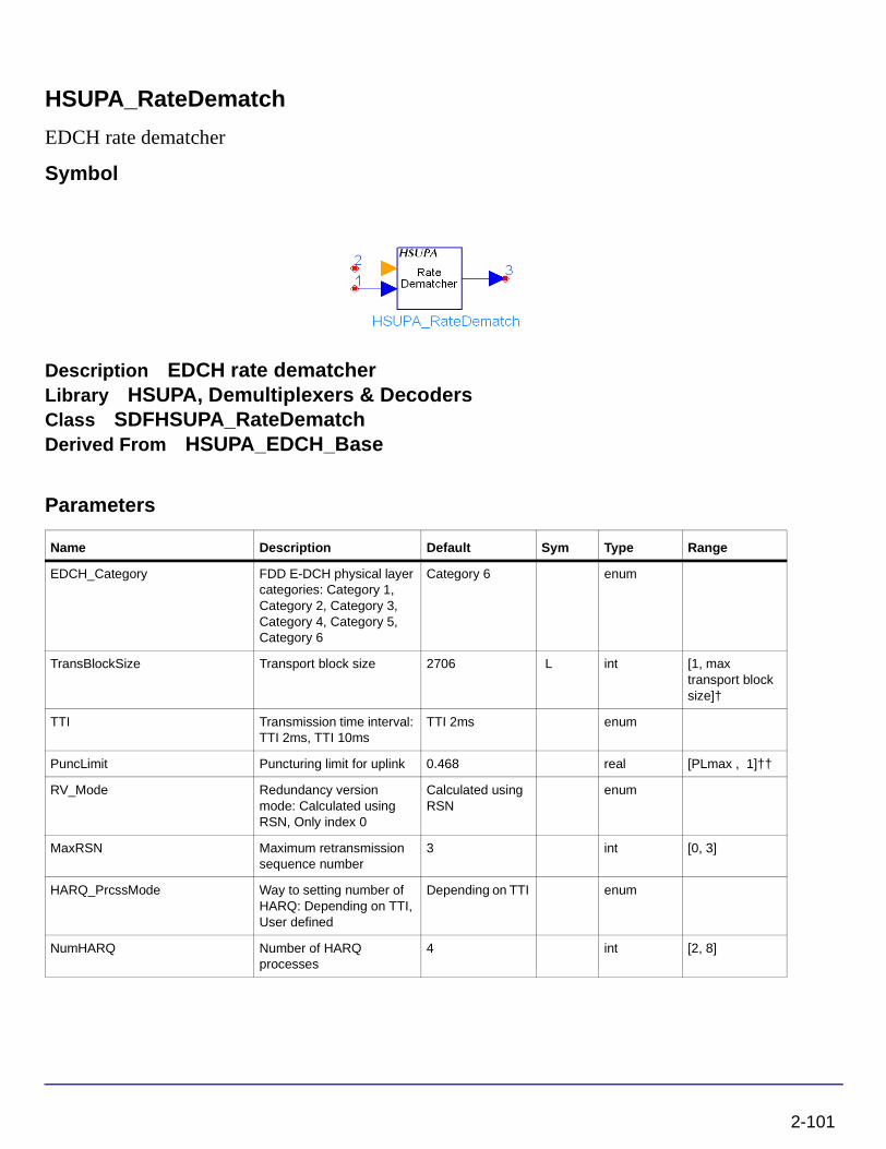
HSUPA_RateDematch
EDCH rate dematcher
Symbol
Description EDCH rate dematcherLibrary HSUPA, Demultiplexers & DecodersClass SDFHSUPA_RateDematchDerived From HSUPA_EDCH_Base
Parameters
Name Description Default Sym Type Range
EDCH_Category FDD E-DCH physical layer categories: Category 1, Category 2, Category 3, Category 4, Category 5, Category 6
Category 6 enum
TransBlockSize Transport block size 2706 L int [1, max transport block size]†
TTI Transmission time interval: TTI 2ms, TTI 10ms
TTI 2ms enum
PuncLimit Puncturing limit for uplink 0.468 real [PLmax , 1]††
RV_Mode Redundancy version mode: Calculated using RSN, Only index 0
Calculated using RSN
enum
MaxRSN Maximum retransmission sequence number
3 int [0, 3]
HARQ_PrcssMode Way to setting number of HARQ: Depending on TTI, User defined
Depending on TTI enum
NumHARQ Number of HARQ processes
4 int [2, 8]
2-101

HSUPA Components
Pin Inputs
Pin Outputs
Notes/Equations
1. This model is used to implement rate dematch for HSUPA uplink.
Each firing, ((TransBlockSize + number of padding bits) * 3 + code block number * 12) Output tokens are generated while Ndata Input tokens are consumed. Determination of Ndata, spreading factor, and number of E-DPDCH is described in 4.8.4.1 in [2].
A simple way to get the value of code block number, code block size and the number of padding bits and their relationship with the value of TransBlockSize is just to run the model HSUPA_CodeBlkSeg with wanted TransBlockSize in a minimal runnable design. The information will then be displayed in the simulation window.
A simple way to get the value of Ndata, spreading factor and number of E-DPDCH used with wanted TTI and TransBlockSize is to build and run a minimal test design of this model. The information will be displayed in the simulation window.
2. This model implements the converse operation of HSUPA_RateMatch. For more information, see “HSUPA_RateMatch” on page 2-104.
3. The received signal for each HARQ process is buffered in this model. If the input of RSN is 0, current input data will be stored into the buffer of the current HARQ process directly. If the input of RSN is larger than 0, it means the received signal is a redundancy version and there is a previous version stored in the buffer of the current HARQ process. Versions of received signal are combined and then stored into the buffer of the current HARQ process. The data in the buffer for the current HARQ process are then fed into channel decoder(s).
TransBlockIgnored Transport block Ignored due to system delay
1 int [0, 5]
† Please refer to table of FDD E-DCH physical layer categories. ††PLmax is 0.33 for Category 6 and is 0.44 for all other categories.
Pin Name Description Signal Type
1 Input input real
2 RSN retransmission sequence number int
Pin Name Description Signal Type
3 Output output real
Name Description Default Sym Type Range
2-102

4. Since the soft combination described above depends on HARQ process and rate dematch is implemented TTI by TTI, the beginning of the first HARQ process must be known to the model. Generally, receiver may introduce some delays into data stream. The value of delay shall be sent to this model by setting parameter TransBlockIgnored.
References
[1] 3GPP Technical Specification TS 25.211, "Physical channels and mapping of transport channels onto physical channels (FDD)," Version 6.7.0, Dec. 2005.
[2] 3GPP Technical Specification TS 25.212, "Multiplexing and channel coding (FDD)," Version 6.7.0, Dec. 2005.
[3] 3GPP Technical Specification TS 25.213, "Spreading and modulation (FDD)," Version 6.5.0, Mar. 2006.
2-103

HSUPA Components
HSUPA_RateMatch
EDCH rate matcher
Symbol
Description EDCH rate matcherLibrary HSUPA, Multiplexers & CodersClass SDFHSUPA_RateMatchDerived From HSUPA_EDCH_Base
Parameters
Name Description Default Sym Type Range
EDCH_Category FDD E-DCH physical layer categories: Category 1, Category 2, Category 3, Category 4, Category 5, Category 6
Category 6 enum
TransBlockSize Transport block size 2706 L int [1, max transport block size]†
TTI Transmission time interval: TTI 2ms, TTI 10ms
TTI 2ms enum
PuncLimit Puncturing limit for uplink 0.468 real [PLmax , 1]††
RV_Mode Redundancy version mode: Calculated using RSN, Only index 0
Calculated using RSN
enum
MaxRSN Maximum retransmission sequence number
3 int [0, 3]
HARQ_PrcssMode Way to setting number of HARQ: Depending on TTI, User defined
Depending on TTI enum
NumHARQ Number of HARQ processes
4 int [2, 8]
† Please refer to table of FDD E-DCH physical layer categories. ††PLmax is 0.33 for Category 6 and is 0.44 for all other categories.
2-104

Pin Inputs
Pin Outputs
Notes/Equations
1. This model is used to implement rate match defined in 4.8.4 in [2] for HSUPA uplink
Each firing, Ndata Output tokens are generated while ((TransBlockSize + number of padding bits) * 3 + code block number * 12) Input tokens consumed. Determination of Ndata, spreading factor, and number of E-DPDCH is described in 4.8.4.1 in [2].
A simple way to get the value of code block number, code block size, and the number of padding bits and their relationship with the value of TransBlockSize is to run the model HSUPA_CodeBlkSeg with wanted TransBlockSize in a minimal runnable design. The information will then be displayed in the simulation window.
A simple way to get the value of Ndata, spreading factor, and number of E-DPDCH used with wanted TTI and TransBlockSize is to build and run a minimal test design of this model. The information will be displayed in the simulation window.
2. If the value of RV_Mod is set to “Calculated using RSN”, the RSN input, the NumHARQ value, and current TTI number will be used to calculate the RV value according to Table 16 of Relation between RSN value and E-DCH RV Index in 4.9.2.2 in [2]. This table is copied into Table 2-5. If HARQ_PrcssMode is set to “Depending on TTI”, NumHARQ is set to 8 for TTI 2ms and 4 for TTI 10 ms. Otherwise, the user can set the value of NumHARQ.
Pin Name Description Signal Type
1 Input input int
2 RSN retransmission sequence number int
Pin Name Description Signal Type
3 Output output int
Table 2-5. Relation between RSN value and E-DCH RV Index
RSN Value Nsys / Ne,data,j <1/2 1/2 = Nsys / Ne,data,j
E-DCH RV Index E-DCH RV Index
0 0 0
1 2 3
2 0 2
3 [ TTIN/NARQ mod 2 ] x 2 TTIN/NARQ mod 4
2-105

HSUPA Components
3. The process of bit separation, rate match with specific RV value, and bit collection can be found in 4.8.4.2-4.8.4.4 in [2].
References
[1] 3GPP Technical Specification TS 25.211, "Physical channels and mapping of transport channels onto physical channels (FDD)," Version 6.7.0, Dec. 2005.
[2] 3GPP Technical Specification TS 25.212, "Multiplexing and channel coding (FDD)," Version 6.7.0, Dec. 2005.
[3] 3GPP Technical Specification TS 25.213, "Spreading and modulation (FDD)," Version 6.5.0, Mar. 2006.
2-106

HSUPA_RF_EVM
EVM and Phase Discontinuity Measurements
Symbol
Description EVM and Phase Discontinuity MeasurementsLibrary HSUPA, MeasurementClass TSDFHSUPA_RF_EVM
Parameters
Name Description Default Unit Type Range
RLoad input resistance DefaultROut Ohm real (0, ∞)
RTemp temperature of resistor, in celsius
DefaultRTemp real [-273.15, ∞)
ExcessBW excess bandwidth of raised cosine filters
0.22 real (0.0, 1.0)
FilterLength length of raised cosine filters in number of symbols
16 int [1, ∞]
SamplesPerChip samples per chip 8 int [1, 256]
LinkDir link direction: Downlink, Uplink
Uplink enum
ScrambleCode index of scramble code 0 int [0, 511] for downlink; [0, 16777215] for uplink
ULScrambleType uplink scramble code type: LONG, SHORT
LONG enum
ScrambleOffset scramble offset in downlink channels
0 int [0, 15]
DLScrambleType downlink scramble code type: Normal, RightAlternate, LeftAlternate
Normal enum
2-107

HSUPA Components
Pin Inputs
SpreadCode index of spread code 0 int [0, 255] for uplink DPCCH; [0, SF-1] for downlink; SF is set by SlotFormat
SlotFormat slot format 0 int [0, 5] for uplink DPCCH; [0, 16 ] for downlink DPCH
StartSlot number of slot to be ignored
0 int [0, ∞)
SlotNum number of slots measured 2 int [1, 15]
SCH switch for SCH: OFF, ON ON enum
CPICH switch for CPICH: OFF, ON OFF enum
DUT_DelayBound Search length 0.00001 sec sec real (0, (400.0/3840000))
EVMValue EVM value expression options: EVM_Ratio, EVM_Percent
EVM_Percent enum
Correct_IQ_Offset switch for IQ offset correction: NO, YES
YES enum
ExcludeTransition select YES for predictable power changes: NO, YES
YES enum
Pin Name Description Signal Type
1 RFin input RF signal timed
2 ref reference signals complex
Name Description Default Unit Type Range
2-108

Notes/Equations
1. This subnetwork model measures EVM and Phase Discontinuity that are used to evaluate modulation accuracy. The schematic for this subnetwork is shown in Figure 2-13.
Figure 2-13. HSUPA_RF_EVM Schematic
2. EVM is measured by comparing the reference signals with the signal to be tested. Root-raised cosine filtering is performed before each test and reference signal.
3. For more information, see “HSUPA_EVM” on page 2-73, and see 3GPPFDD_EVM_NonSyn and 3GPPFDD_EVM in the 3GPP W-CDMA Design Library documentation.
4. Use of this model is demonstrated in the user equipment transmitter example: File > Example Project > HSUPA > HSUPA_UE_Tx_prj > UE_Tx_EVM.dsn. Simulation results are provided in the design’s data display window.
References
[1] 3GPP Technical Specification TS 25.211, "Physical channels and mapping of transport channels onto physical channels (FDD)," Version 6.7.0, Dec. 2005.
[2] 3GPP Technical Specification TS 25.212, "Multiplexing and channel coding (FDD)," Version 6.7.0, Dec. 2005.
[3] 3GPP Technical Specification TS 25.213, "Spreading and modulation (FDD)," Version 6.5.0, Mar. 2006.
[4] 3GPP Technical Specification TS 25.214, "Physical layer procedures (FDD)," Version 6.8.0, Mar. 2006.
2-109

HSUPA Components
[5] 3GPP Technical Specification TS 25.101, "UE Radio transmission and Reception (FDD)," Version 6.11.0, Mar. 2006.
[6] 3GPP Technical Specification TS 25.104, "UTRA (BS) FDD: Radio transmission and Reception," Version 6.12.0, Mar. 2006.
[7] 3GPP Technical Specification TS 25.141, "Base station conformance test," Version 6.13.0, Mar. 2006.
[8] 3GPP Technical Specification TS 34.121, "Radio transmission and reception (FDD)," Version 7.0.0, Mar. 2006.
2-110

HSUPA_RF_OutputPower
HSUPA output power measurements
Symbol
Description HSUPA output power measurementsLibrary HSUPA, MeasurementClass TSDFHSUPA_RF_OutputPowerDerived From HSUPA_SubcktBase
Parameters
Name Description Default Sym Unit Type Range
RLoad Input resistance DefaultRLoad Ohm real (0, ∞)
FCarrier Carrier frequency 1950MHz Hz real (0, ∞)
SamplesPerChip Samples per chip 8 S int [2, 32]
ScrambleCode Index of scramble code 0 int [0, 512] for downlink; [0, 16777215] for uplink
Scramble scramble code type: LONG, SHORT
LONG enum
SlotFormat Slot format 0 int [0, 5] for uplink DPCCH
CM_k Slope factor for calculating cubic metric
1.56 real [1.0, 3.0]
SearchLength Search length .00001 sec sec real (0, (400.0/3840000))
StartSlot number of slot to be ignored
0 int [0, ∞)
SlotNum number of slots measured 1 int [1, 30]
2-111
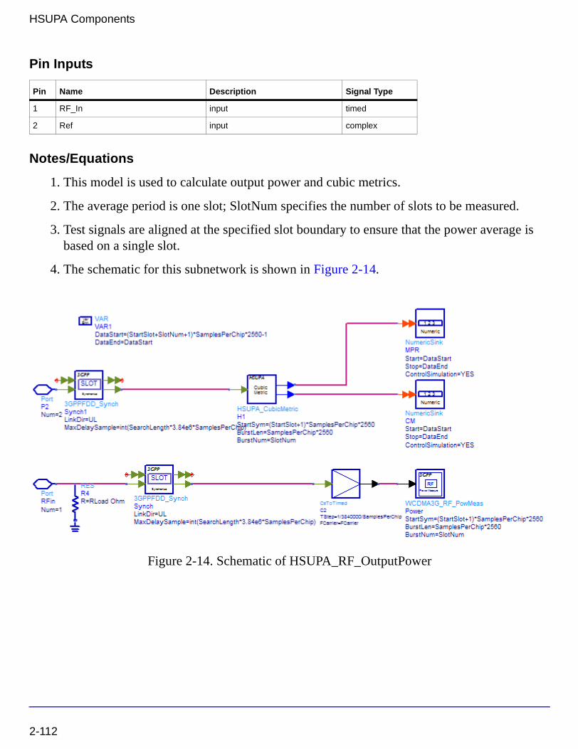
HSUPA Components
Pin Inputs
Notes/Equations
1. This model is used to calculate output power and cubic metrics.
2. The average period is one slot; SlotNum specifies the number of slots to be measured.
3. Test signals are aligned at the specified slot boundary to ensure that the power average is based on a single slot.
4. The schematic for this subnetwork is shown in Figure 2-14.
Figure 2-14. Schematic of HSUPA_RF_OutputPower
Pin Name Description Signal Type
1 RF_In input timed
2 Ref input complex
2-112

5. Cubic Metric (CM) is based on the UE transmit channel configuration and is given by
CM =CEIL{ [20 * log10 ((v_norm 3) rms) – 20 * log10 ((v_norm_ref 3) rms)] / k, 0.5}
where:
• CEIL{ x, 0.5 } means rounding upwards to closest 0.5dB, i.e. CM∈ [0, 0.5, 1.0, 1.5, 2.0, 2.5, 3.0, 3.5]
• k is 1.85 for signals where all channelisation codes meet the following criteria CSF, N
where N < SF/2
• k is 1.56 for signals where any channelisation code meet the following criteria CSF, N
where N ≥ SF/2
• v_norm_ref is the normalized voltage waveform of the reference signal (12.2 kbps AMR Speech) and 20 * log10 ((v_norm_ref 3) rms is 1.5237 dB.
6. MPR equals the larger value of CM-1 and 0.
7. For more information, see 3GPPFDD_Synch and WCDMA3G_RF_PowMeas in the 3GPP W-CDMA Design Library documentation.
References
[1] 3GPP Technical Specification TS 25.211, "Physical channels and mapping of transport channels onto physical channels (FDD)," Version 6.7.0, Dec. 2005.
[2] 3GPP Technical Specification TS 25.212, "Multiplexing and channel coding (FDD)," Version 6.7.0, Dec. 2005.
[3] 3GPP Technical Specification TS 25.213, "Spreading and modulation (FDD)," Version 6.5.0, Mar. 2006.
[4] 3GPP Technical Specification TS 25.101, "UE Radio transmission and Reception (FDD)," Version 6.11.0, Mar. 2006.
2-113
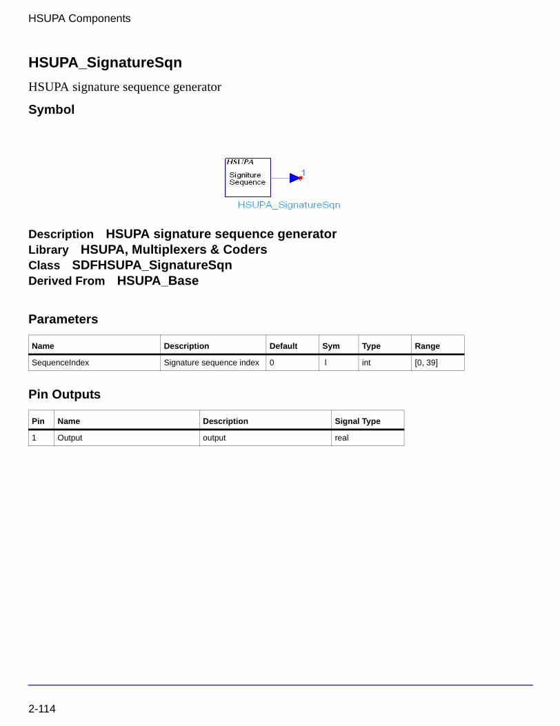
HSUPA Components
HSUPA_SignatureSqn
HSUPA signature sequence generator
Symbol
Description HSUPA signature sequence generatorLibrary HSUPA, Multiplexers & CodersClass SDFHSUPA_SignatureSqnDerived From HSUPA_Base
Parameters
Pin Outputs
Name Description Default Sym Type Range
SequenceIndex Signature sequence index 0 l int [0, 39]
Pin Name Description Signal Type
1 Output output real
2-114

Notes/Equations
1. This model generates the E-DCH Relative Grant Channel (E-RGCH) or the E-DCH Hybrid ARQ Indicator Channel (E-HICH) signature sequence according to SequenceIndex as defined in [1].
2. Each firing, one token is produced.
3. The orthogonal signature sequences Css,40,m(i) is given by Table 2-6 and the index m(i) in
slot i is giving by Table 2-7.
Table 2-6. E-RGCH and E-HICH signature sequences
Css,40,0 -1 -1 -1 1 -1 1 -1 -1 1 1 -1 -1 1 -1 1 1 -1 1 1 -1 -1 -1 -1 -1 -1 -1 -1 1 -1 1 -1 -1 1 1 1 1 1 -1 -1 -1
Css,40,1 -1 1 1 -1 -1 1 1 1 -1 -1 1 -1 1 1 -1 -1 -1 -1 1 1 1 -1 -1 -1 -1 1 -1 -1 -1 -1 -1 -1 -1 1 1 -1 1 1 -1 -1
Css,40,2 -1 -1 -1 1 -1 1 1 1 -1 -1 -1 -1 1 -1 -1 1 1 -1 -1 1 1 -1 1 1 1 -1 -1 1 1 1 -1 1 -1 -1 -1 -1 -1 -1 -1 -1
Css,40,3 1 -1 -1 -1 -1 -1 -1 1 1 1 -1 1 -1 1 -1 1 -1 -1 1 1 -1 1 -1 -1 1 1 -1 1 -1 -1 1 1 -1 -1 1 -1 -1 -1 -1 -1
Css,40,4 1 1 1 -1 -1 1 -1 1 -1 -1 1 1 1 -1 1 1 1 1 1 1 -1 1 1 1 -1 -1 -1 1 1 -1 1 -1 1 -1 1 1 -1 1 -1 -1
Css,40,5 -1 1 -1 -1 1 1 1 -1 1 1 -1 1 1 1 -1 1 1 1 -1 -1 1 -1 -1 1 -1 1 -1 1 -1 -1 1 -1 1 -1 -1 -1 -1 1 1 -1
Css,40,6 1 1 -1 -1 -1 1 1 -1 1 1 -1 -1 1 -1 -1 -1 -1 1 1 -1 1 1 1 -1 1 -1 1 -1 1 -1 -1 1 1 -1 1 -1 -1 1 -1 1
Css,40,7 -1 1 -1 1 1 1 -1 -1 -1 -1 -1 1 1 1 1 -1 -1 -1 1 -1 -1 -1 1 -1 1 1 -1 -1 1 1 1 1 -1 -1 1 1 -1 1 1 -1
Css,40,8 1 1 -1 1 1 -1 1 1 1 1 -1 -1 -1 -1 1 -1 1 -1 1 1 1 1 -1 1 -1 -1 -1 -1 -1 1 -1 -1 -1 -1 1 1 -1 1 1 -1
Css,40,9 -1 1 -1 -1 -1 -1 1 -1 -1 -1 -1 1 -1 -1 1 1 1 -1 1 -1 1 -1 -1 1 1 -1 1 1 -1 -1 1 1 -1 1 1 1 1 1 -1 1
Css,40,10 -1 1 1 -1 1 1 -1 1 1 1 1 -1 1 -1 1 1 -1 -1 -1 1 -1 -1 -1 -1 1 -1 1 1 -1 -1 -1 1 -1 -1 -1 1 -1 1 1 1
Css,40,11 -1 1 -1 -1 -1 -1 -1 1 1 1 -1 -1 -1 1 1 -1 1 1 -1 1 -1 -1 1 1 1 1 -1 -1 1 -1 -1 1 1 1 -1 1 1 1 -1 -1
Css,40,12 -1 -1 -1 -1 1 -1 1 1 -1 -1 -1 -1 -1 1 1 1 -1 1 1 1 1 -1 1 -1 -1 1 1 1 1 -1 -1 -1 1 -1 1 1 -1 -1 1 1
Css,40,13 1 1 1 1 -1 -1 1 -1 -1 -1 1 -1 -1 1 1 1 -1 1 -1 -1 1 1 -1 -1 1 1 -1 1 -1 1 -1 1 1 -1 -1 1 -1 1 -1 -1
Css,40,14 -1 1 1 1 -1 -1 -1 -1 1 1 1 -1 -1 1 -1 1 1 -1 1 -1 -1 -1 1 1 -1 1 1 1 1 1 -1 -1 -1 -1 1 -1 -1 1 -1 1
Css,40,15 -1 -1 1 1 -1 1 1 1 1 1 1 1 1 1 1 -1 1 1 1 1 1 -1 -1 1 1 1 1 -1 -1 1 1 1 1 -1 1 1 -1 -1 -1 1
Css,40,16 1 -1 -1 -1 -1 1 -1 -1 -1 -1 -1 -1 1 1 1 -1 1 -1 -1 -1 -1 1 -1 1 -1 1 1 -1 -1 -1 -1 -1 -1 -1 -1 1 -1 -1 -1 1
Css,40,17 1 -1 1 -1 1 1 1 -1 1 1 1 -1 1 1 1 1 1 -1 1 -1 1 1 1 1 1 1 -1 1 1 -1 -1 1 -1 1 1 1 1 -1 1 -1
Css,40,18 1 1 -1 1 -1 1 1 1 1 1 -1 1 1 1 1 1 -1 -1 -1 1 1 1 1 -1 -1 1 1 1 1 1 1 -1 -1 1 -1 1 1 1 -1 1
Css,40,19 1 1 -1 1 1 1 -1 1 -1 -1 -1 -1 1 1 -1 1 1 1 1 1 -1 1 -1 1 1 1 1 1 -1 1 -1 1 1 1 1 -1 1 1 1 1
Css,40,20 1 1 1 -1 1 1 -1 1 -1 1 -1 1 -1 -1 -1 1 -1 -1 1 -1 1 -1 -1 1 1 1 1 -1 1 1 -1 -1 1 1 -1 1 -1 -1 -1 -1
Css,40,21 -1 1 1 -1 -1 -1 -1 1 -1 1 -1 -1 1 -1 -1 1 1 -1 -1 -1 1 1 1 -1 -1 1 -1 -1 -1 1 1 1 1 -1 1 1 1 -1 1 1
Css,40,22 -1 -1 -1 1 -1 -1 -1 1 -1 1 1 -1 1 1 -1 -1 -1 -1 1 -1 1 1 -1 1 1 -1 -1 1 1 -1 1 -1 1 1 -1 1 -1 1 1 1
2-115

HSUPA Components
Css,40,23 1 -1 -1 -1 -1 1 1 1 1 -1 1 1 -1 -1 -1 -1 1 -1 -1 -1 -1 -1 1 -1 1 1 -1 1 -1 1 -1 -1 1 1 1 1 -1 1 1 1
Css,40,24 -1 -1 -1 1 1 1 -1 -1 1 -1 1 -1 -1 -1 -1 1 1 -1 1 1 1 1 1 -1 1 1 1 -1 -1 -1 1 -1 1 -1 -1 1 1 1 -1 -1
Css,40,25 -1 1 -1 -1 1 -1 -1 -1 1 -1 1 1 1 -1 -1 -1 -1 1 1 1 1 1 1 1 -1 1 -1 1 -1 1 -1 1 -1 1 -1 1 -1 -1 -1 1
Css,40,26 -1 -1 1 1 1 1 1 1 -1 1 -1 1 -1 -1 1 -1 -1 -1 1 -1 -1 1 1 1 -1 1 -1 1 -1 -1 -1 1 1 -1 -1 -1 1 1 -1 1
Css,40,27 1 -1 1 -1 -1 1 -1 1 1 -1 -1 -1 -1 1 -1 -1 -1 1 1 -1 1 -1 1 1 -1 -1 1 1 -1 1 1 1 -1 -1 -1 1 1 1 1 -1
Css,40,28 1 1 -1 1 1 1 -1 1 1 -1 1 -1 -1 1 1 1 -1 -1 -1 -1 1 -1 1 1 -1 -1 -1 -1 -1 -1 1 1 1 1 1 -1 -1 -1 -1 1
Css,40,29 -1 1 -1 -1 -1 1 -1 -1 -1 1 1 1 -1 1 1 -1 -1 -1 -1 1 1 1 1 1 1 -1 1 1 -1 1 -1 -1 1 -1 1 -1 1 -1 1 -1
Css,40,30 -1 1 1 -1 1 -1 1 1 1 -1 -1 -1 1 1 1 -1 1 -1 1 -1 -1 1 1 -1 1 -1 1 1 -1 1 1 -1 1 1 -1 -1 -1 -1 -1 -1
Css,40,31 -1 1 -1 -1 -1 1 1 1 1 -1 1 -1 -1 -1 1 1 -1 1 1 -1 -1 1 -1 1 1 1 -1 -1 1 1 1 -1 -1 -1 -1 -1 1 -1 1 1
Css,40,32 1 1 1 1 -1 -1 1 -1 1 -1 -1 1 1 1 -1 1 -1 -1 1 1 -1 -1 1 1 1 -1 -1 -1 -1 -1 -1 -1 1 -1 -1 1 1 -1 1 1
Css,40,33 -1 -1 -1 -1 1 -1 1 1 1 -1 1 1 1 1 -1 1 -1 -1 -1 -1 -1 1 -1 1 -1 -1 1 -1 1 1 -1 1 1 -1 1 1 1 1 -1 -1
Css,40,34 1 -1 -1 -1 1 -1 -1 1 -1 1 1 1 1 1 1 1 1 1 1 -1 1 -1 1 -1 1 -1 -1 -1 -1 1 -1 -1 -1 -1 -1 -1 1 1 -1 1
Css,40,35 -1 -1 1 1 -1 -1 -1 1 1 -1 -1 1 1 -1 1 1 -1 1 -1 -1 1 1 1 1 1 1 1 -1 -1 -1 -1 -1 -1 1 1 -1 -1 1 1 -1
Css,40,36 -1 1 1 1 1 1 -1 1 1 -1 -1 1 -1 1 -1 -1 1 1 -1 -1 1 1 -1 -1 1 -1 -1 1 1 -1 -1 -1 -1 -1 1 1 1 -1 -1 1
Css,40,37 1 -1 1 -1 1 -1 -1 -1 1 -1 -1 -1 1 -1 1 -1 -1 -1 -1 1 1 -1 -1 1 1 1 -1 1 1 1 1 -1 1 -1 1 -1 1 1 -1 1
Css,40,38 -1 -1 1 -1 1 1 1 -1 -1 1 -1 -1 -1 1 -1 1 -1 1 -1 1 -1 1 1 1 1 -1 -1 -1 -1 1 1 -1 -1 1 1 1 -1 1 -1 1
Css,40,39 -1 -1 1 -1 -1 1 -1 -1 1 -1 -1 1 -1 1 1 1 1 -1 1 1 1 1 -1 -1 -1 -1 -1 -1 1 1 -1 1 1 1 -1 -1 -1 1 1 1
Table 2-6. E-RGCH and E-HICH signature sequences
2-116

Table 2-7. E-HICH and E-RGCH signature hopping pattern
Sequence index l
Row index m(i) for slot i
i mod 3 = 0 i mod 3 = 1 i mod 3 = 2
0 0 2 13
1 1 18 18
2 2 8 33
3 3 16 32
4 4 13 10
5 5 3 25
6 6 12 16
7 7 6 1
8 8 19 39
9 9 34 14
10 10 4 5
11 11 17 34
12 12 29 30
13 13 11 23
14 14 24 22
15 15 28 21
16 16 35 19
17 17 21 36
18 18 37 2
19 19 23 11
20 20 39 9
21 21 22 3
22 22 9 15
23 23 36 20
24 24 0 26
25 25 5 24
26 26 7 8
27 27 27 17
28 28 32 29
29 29 15 38
30 30 30 12
31 31 26 7
32 32 20 37
2-117
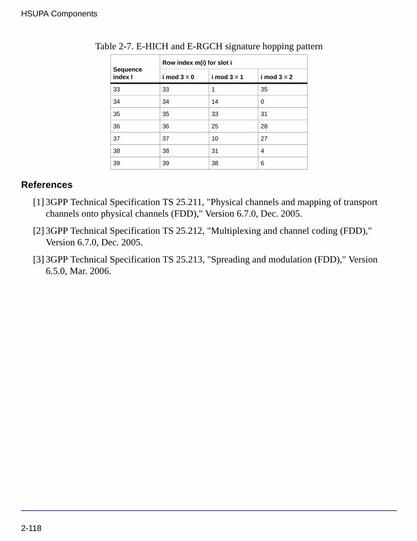
HSUPA Components
References
[1] 3GPP Technical Specification TS 25.211, "Physical channels and mapping of transport channels onto physical channels (FDD)," Version 6.7.0, Dec. 2005.
[2] 3GPP Technical Specification TS 25.212, "Multiplexing and channel coding (FDD)," Version 6.7.0, Dec. 2005.
[3] 3GPP Technical Specification TS 25.213, "Spreading and modulation (FDD)," Version 6.5.0, Mar. 2006.
33 33 1 35
34 34 14 0
35 35 33 31
36 36 25 28
37 37 10 27
38 38 31 4
39 39 38 6
Table 2-7. E-HICH and E-RGCH signature hopping pattern
Sequence index l
Row index m(i) for slot i
i mod 3 = 0 i mod 3 = 1 i mod 3 = 2
2-118

HSUPA_Spread
HSUPA spreader
Symbol
Description HSUPA spreaderLibrary HSUPA, Multiplexers & CodersClass SDFHSUPA_SpreadDerived From HSUPA_Base
Parameters
Pin Inputs
Name Description Default Type
DPDCH_Configured Setting to YES if DPDCH is configured, otherwise NO: NO, YES
NO enum
HSDPCCH_Configured Setting to YES if HS-DPCCH is configured, otherwise NO: NO, YES
NO enum
Pin Name Description Signal Type
1 DPDCH DPDCH int
2 DPCCH DPCCH int
3 EDPCCH E-DPCCH int
4 HSDPCCH HS-DPCCH int
5 SltF_D slot format of DPDCH int
6 NumED number of E-DPDCH int
7 SltF_ED slot format of E-DPDCH, only valid when number of E-DPDCH is 1 or 2.
int
8 GainD gain factor of DPDCH over DPCCH, in dB real
9 GainED gain factor of E-DPDCH over DPCCH, in dB real
10 GainEC gain factor of E-DPCCH over DPCCH, in dB real
2-119

HSUPA Components
Pin Outputs
Notes/Equations
1. This model is used to spread, power-scale, and multiplex uplink signals according to [3].
Each firing, 2560 Output tokens are generated when 2560 DPDCH tokens, 10 DPCCH tokens, 10 EDPCCH tokens, 10 HSDPCCH tokens, 1 SltF_D token, 1 NumED token, 1 SltF_ED token, 1 GainD token, 1 GainED token, 1 GainEC token, 1 GainHS token and 2560 EDPDCH tokens are consumed.
2. The input of DPDCH and E-DPDCH must be repeated to chip rate before it is fed into this model. The spreading code will be multiplied directly with input signal.
3. Table 0 of Maximum number of simultaneous uplink dedicated channels in [3] is copied here in Table 2-8. Since whenever there are enhanced uplink channels, the maximum number of DPDCH is less than 2, the input of DPDCH is not designed as a multiple port.
4. SltF_D is the slot format for DPDCH, which can be found in 5.2.1.1[1]. This input is used to determine SF of DPDCH. It determines the spreading code at the same time because according to [3], when only one DPDCH is to be transmitted, DPDCH1 shall be spread by code cd,1 = Cch,SF,k where SF is the spreading factor of DPDCH1 and k= SF / 4.
5. Num_ED and SltF_ED are the number and slot format of E-DPDCH, which can be found in 5.2.1.3[1]. SltF_ED is used to determine SF of each E-DPDCH. When Num_ED is 4, SltF_ED is ignored and the spreading code of E-DPDCH1 and E-DPDCH2 is Cch,2,1. The
spreading code of E-DPDCH3 and E-DPDCH4 is always Cch,4,1.
11 GainHS gain factor of HS-DPCCH over DPCCH, in dB real
12 EDPDCH E-DPDCH multiple int
Pin Name Description Signal Type
13 Output output complex
Table 2-8. Maximum number of simultaneous uplink dedicated channels
Configuration # DPDCH HS-DPCCH E-DPDCH E-DPCCH
1 6 1 - -
2 1 1 2 1
3 - 1 4 1
Pin Name Description Signal Type
2-120

6. If parameter DPDCH_Configured is set to YES, Nmax-dpdch is 1, while if it is set to NO,
Nmax-dpdch is 0. Table 1E of Channelisation code for E-DPDCH in [3] is copied into
Table 2-9.
7. Related information in Table 1D of Channelisation code of HS-DPCCH in [3] is copied into Table 2-10.
8. The DPCCH is defined as power reference of other uplink channels in this model. For example, GainED is the gain of power level of E-DPDCH over DPCCH in dB units. The factor multiplied to the data of DPCCH is 1, while the factor multiplied to the data of each E-DPDCH is 20*log(GainED).
9. GainED is gain for each E-DPDCH. If there are four E-DPDCHs, GainED is the gain for E-DPDCH3 and E-DPDCH4. The gain for E-DPDCH1 and E-DPDCH2 is GainED+3dB.
For more information, please refer to 5.1.2.5B.2.3 in [4].
Table 2-9. Channelisation code for E-DPDCH
Nmax-dpdch E-DPDCHk Channelisation code Ced,k
0 E-DPDCH1 Cch,SF,SF/4 if SF ≥ 4
Cch,2,1 if SF = 2
E-DPDCH2 Cch,4,1 if SF = 4
Cch,2,1 if SF = 2
E-DPDCH3E-DPDCH4
Cch,4,1
1 E-DPDCH1 Cch,SF,SF/2
E-DPDCH2 Cch,4,2 if SF = 4
Cch,2,1 if SF = 2
Table 2-10. Channelisation code of HS-DPCCH
Nmax-dpdch Channelisation code chs
0 Cch,256,33
1 Cch,256,64
2-121

HSUPA Components
10. After spreading and power scaling, the uplink channels will be mapped to IQ branches. DPCCH is always transmitted in Q branch; E-DPCCH is always transmitted in I branch; HS-DPCCH is always transmitted in Q branch; DPDCH1 is always transmitted in I branch;
Table 1C of the IQ branch mapping for E-DPDCH in [3] is copied into Table 2-11.
11. The uplink signal is normalized to ensure its RMS value is 1.
References
[1] 3GPP Technical Specification TS 25.211, "Physical channels and mapping of transport channels onto physical channels (FDD)," Version 6.7.0, Dec. 2005.
[2] 3GPP Technical Specification TS 25.212, "Multiplexing and channel coding (FDD)," Version 6.7.0, Dec. 2005.
[3] 3GPP Technical Specification TS 25.213, "Spreading and modulation (FDD)," Version 6.5.0, Mar. 2006.
[4] GPP Technical Specification TS 25.214, "Physical layer procedures (FDD)," Version 6.8.0, Mar. 2006.
Table 2-11. IQ branch mapping for E-DPDCH
Nmax-dpdchHS-DSCH configured E-DPDCHk iqed,k
0 No/Yes E-DPDCH1 1
E-DPDCH2 j
E-DPDCH3 1
E-DPDCH4 j
1 No E-DPDCH1 j
E-DPDCH2 1
1 Yes E-DPDCH1 1
E-DPDCH2 j
2-122

HSUPA_UL_Rake
HSUPA uplink receiver
Symbol
Description HSUPA uplink receiverLibrary HSUPA, ReceiversClass SDFHSUPA_UL_RakeDerived From 3GPPHSUPA_UL_Receiver_Base
Parameters
Name Description Default Type Range
SlotFormat slot format 0 int †
ScrambleCode index of scramble code 0 int [0, 512] for downlink; [0, 16777215] for uplink
Scramble scramble code type: LONG, SHORT
LONG enum
SampleRate sample rate 8 int [1, 256]
MaxDelaySample maximum delay boundary, in terms of samples
0 int [0, 2559] for RAKE receiver; [0, 102400] in other models
ChannelType select the channel type to be processed: CH_GAUSSIAN, CH_FADING
CH_GAUSSIAN enum
ChannelInfo fading channel information source: Known, Estimated
Known enum
ChannelInfoOffset offset between spread code and channel information in terms of sample
0 int [0, MaxDelaySample]
PathSearch path search frequency: EverySlot, Once
Once enum
2-123

HSUPA Components
Pin Inputs
SearchMethod path search method: Coherent, NonCoherent, Combined
Coherent enum
SearchSlotsNum number of slots for path search
1 int [1, 12]
PathNum number of Rake fingers 1 int [1, 6]
PathDelaySample delay for each finger, in terms of samples
0 int array [0, MaxDelaySample]; array size shall be equal to PathNum
EstSlotsNum Number of slots for channel estimation
1 int [1, 3]
UseMovingEstWindow If use moving window in channel estimation: NO, YES
NO enum
UsePastSearch If use past samples for path searching: NO, YES
NO enum
TTI Transmission time interval: TTI 2ms, TTI 10ms
TTI 2ms enum
DPDCH_Configured Setting to YES if DPDCH is configured, otherwise NO: NO, YES
NO enum
HSDPCCH_Configured Setting to YES if HS-DPCCH is configured, otherwise NO: NO, YES
NO enum
† [0:5] for uplink DPCCH; [0:16] for downlink DPCH; [0:17] for downlink SCCPCH; [0:5] for uplink PCPCH (Ver 03_00); [0:2] for uplink PCPCH (Ver 12_00); [0:1] for uplink PCPCH (Ver 03_02).
Pin Name Description Signal Type
1 inChip input data stream complex
2 NumED number of E-DPDCH int
3 SltF_ED slot format of E-DPDCH int
4 inChM input known channel information multiple complex
Name Description Default Type Range
2-124

Pin Outputs
Notes/Equations
1. This model is used to demodulate and despread HSUPA uplink signals at a 3.84MHz chip rate. Such signals can be corrupted by multipath fading channel and additive Gaussian noise.
Each firing, 2560 EDPDCH tokens, 10 EDPCCH tokens, 1 DPCCH tokens, 1 SlotIndex token, 1 Delay token, and 2560 outChM tokens are produced when 2560*SamplesPerChip inChip and inChM tokens, 1 Num_ED token, and 1 SltF_ED token are consumed.
2. For information about the parameters related to the configuration of uplink channels, see “HSUPA_Spread” on page 2-119.
3. To despread and demodulate a CDMA signal, the channel information and path delay information must be determined. Errors in channel estimation and path search deteriorate the receiver performance.
4. The signal processing flow inside the model is:
• Input data until slots specified by SearchSlotsNum are received
• Slot index identification
• IQ offset correction to eliminate any DC component.
• Multipath search
• Channel estimation for each path
• Decode and despread of individual path
• SNR estimation for individual path
• Multipath combination
• Output decoded data and SlotIndex to align at the frame boundary
Pin Name Description Signal Type
5 EDPCCH E-DPCCH real
6 PwrN power of noise estimated from DPCCH real
7 SlotIndex slot number int
8 Delay path delay int
9 EDPDCH E-DPDCH multiple real
10 outChM output estimated channel information multiple complex
2-125

HSUPA Components
• Output Delay and channel information (slots delayed are specified by SearchSlotsNum)
5. This model can be configured to work under ideal conditions; in other words, the real time channel information can be input from input pin and the path delay information can be set by the PathDelaySample parameter. The ChannelInfo parameter selects the channel information source from input or estimated inside the model. The delay for each path is expressed in terms of samples as individual elements in the array.
6. f path delay is specified, the SearchSlotsNum is 1.
If the first element in PathDelaySample is 0, the path search is performed inside the receiver model. Otherwise, the numbers specified by PathDelaySample are taken as the delays for each path.
7. The path search is performed by correlating the received signals with the spreading code specified in a window whose size is set by MaxDelaySample. The correlations at different offsets are ranked and the top ones are assumed to be the offsets where the paths could occur.
8. If SearchMethod = Coherent, the correlation will be performed at the pilot bits only. If SearchMethod = NonCoherent, the correlation will be performed on the data field. Note that the coherent correlation obtained over pilot bits is unbiased, while the non-coherent correlation is biased. If SearchMethod = Combined, the coherent and non-coherent correlations are summed as the matrix for path resolution.
9. Another factor that impacts the correlation is the SearchSlotsNum parameter. This parameter sets the number of slots over which the correlation is accumulated. More slots are necessary for a reliable path resolution for signals with noise contamination. Usually, six slots are required if Eb/No is 2 dB. The user must determine the appropriate slot number and
search method for the best trade-off between accuracy and speed.
10. If UsePastSearch = YES, the slots used for searching will use previous slots. For example, if SearchSlotsNum is set to 3 and the index of current slot is 0, then slot -1, 0, 1 will be used for path searching. If SearchSlotsNum is set to 4, slot -1, 0, 1, 2 will be used. slot -1 is the previous slot of slot 0, while slot 1 is the next slot of slot 0,...; If UsePastSearch = NO, slot 0, 1, 2, 3 will be used for path searching.
11. The estimated path delay is output from the pin Delay after slots specified by SearchSlotsNum are received.
12. Because path search results could be biased when channel noise is large, the path delay should be determined before simulation.
For example, if a path delay is 552 nsec and channel gain is -20 dB, if channel noise is large it could be difficult for the Rake receiver to correctly resolve this path. In this case, simply
2-126

increase channel gain to a larger value and decrease the noise level to a very small level. (These changes do not change the channel delay profile.)
The first value of PathDelaySample is set to 0. At start of simulation, the path delay is displayed in the simulation window.
The path delay determined by the Rake receiver is 145. This value has high credibility because it is obtained under large signal-to-noise level. Specify this delay in PathDelaySample and the Rake receiver will use this value during simulation. (The channel gain and noise level will be restored to the original level after the channel delay is fixed.)
13. If the path delay is fixed, the path search is necessary only at the start of simulation; in this case, set PathSearch to Once to save simulation time. Otherwise, PathSearch must be performed for each slot received to update the path delay information that could be dynamic.
14. Channel estimation varies according to channel type.
• If ChannelType = CH_GAUSSIAN, the channel is assumed to be time-invariant and the IQ phase shift is estimated using the pilot field of the signals received so far.
• If ChannelType = CH_FADING, channel characteristics are assumed to be time-variant and more complicated channel estimation must be used. A simple channel estimation is used that takes the fading characteristic averaged over the pilot field of the current slot as the channel information for the entire slot.
15. Generally the pilot in current slots is enough for channel estimation. But if Eb/N0 is very
low, while channel status varies relatively slowly, more slots are necessary for a reliable channel estimation. EstSlotsNum can be used to set the number of slots used for channel estimation.
16. If UsingMovingWindow = YES and ChannelType = CH_FADING, a more complex channel estimation will be used to get more precise channel estimation. The algorithm is as follows:
1. Use channel estimation algorithm described in the second paragraph in Note 14 to get initial channel information.
2. Despread and decode data transmitted in the DPCCH using the channel information.
2-127

HSUPA Components
3. Use the decode data as know information so that all the symbols in DPCCH can be can be think as pilot and used in channel estimation.
4. Set estimation window to be 21 DPCCH symbols centered at each DPCCH symbol of current slot.
5. Moving-average 21 fading characteristics in estimation window to get 10 channel coefficients and each of them used as channel information of correspond symbol interval.
17. Channel information that is estimated or known from input pins is output from the pin outChM for reference. Each firing, 2560 tokens are produced as the channel information for the chips in the slot indicated by SlotIndex.
18. All paths are combined assuming that all the paths are useful in improving the decoding reliability. Some paths with low SNR are actually harmful to the final SNR improvement. The user must determine the PathNum setting for better decoding performance in multipath conditions.
19. Each firing, input tokens is 2560 SampleRate. There is a delay in terms of slots associated with the decoded information. The outputs are aligned at the TTI boundary; for example, if the first received slot index is 0 and TTI is 2ms, the decoded bit stream will be output after three slots.
20. If the HSUPA signal is S(t), this signal may be delayed t1 by some filters (such as the Tx RC filters). So, the delayed signal is S(t-t1) and the signal from 0 to t1 is zero and the real 3GPP signal transmission starts from t1. When the delayed signals pass through a fading channel, the fading factor is applied to the overall signals starting from time 0. The offset t1 must be known if the receiver of the channel information is input from outside; this offset is expressed in terms of samples.
The following description provides more details.
Denote the signal source output as:
S1, S2, S3,..., Si,...
These signals are fed to the transmitter module, and the transmitter module introduces delay (for example, the square root raised-cosine filter introduces the delay that is related with the filter length); denote this delay as N.
The output signals from transmitter module are:
0, 0, 0,..., 0, S1, S2, S3,..., Si,...
The number of 0s is N. These signals are fed to the fading channel model. The fading channel module generates the fading factors, that can be denoted as:
2-128
f1, f2, f3,..., fi,...
These factors will be applied to the input signals. They can also be input to the Rake receiver as phase reference. The resultant faded signals are:
f1 0, f2 0, f3 0, ... , fN 0, ... , fN+1 S1, fN+2 S2
Note that the faded signal must pass the receiver module that introduces additional delay; this does not impact the channel information offset setting.
The channel information being input to the Rake receiver is:
f1, f2, f3, ... , fi, ...
The Rake receiver must know the offset between the faded signal and the known channel information. In this case, the offset is N, and the Rake receiver will take the Nth input from the channel information input and correlate it with the signal start point. The signal start point is determined by the synchronization module implemented inside the Rake receiver.
References
[1] 3GPP Technical Specification TS 25.211, "Physical channels and mapping of transport channels onto physical channels (FDD)," Version 6.7.0, Dec. 2005.
[2] 3GPP Technical Specification TS 25.212, "Multiplexing and channel coding (FDD)," Version 6.7.0, Dec. 2005.
[3] 3GPP Technical Specification TS 25.213, "Spreading and modulation (FDD)," Version 6.5.0, Mar. 2006.
[4] 3GPP Technical Specification TS 25.104, "UTRA (BS) FDD: Radio transmission and Reception," Version 6.12.0, Mar. 2006.
[5] 3GPP Technical Specification TS 25.141, "Base station conformance test," Version 6.13.0, Mar. 2006.
2-129

HSUPA Components
HSUPA_UL_Source
HSUPA uplink signal source
Symbol
Description HSUPA uplink signal sourceLibrary HSUPA, Signal SourcesClass SDFHSUPA_UL_SourceDerived From HSUPA_SubcktBase
Parameters
Name Description Default Sym Unit Type Range
EDCH_Category FDD E-DCH physical layer categories: Category 1, Category 2, Category 3, Category 4, Category 5, Category 6
Category 6 enum
TransBlockSize Transport block size 2706 L int [1, max transport block size]†
TTI Transmission time interval: TTI 2ms, TTI 10ms
TTI 2ms enum
PuncLimit Puncturing limit for uplink 0.468 real [PLmax , 1]††
RV_Mode Redundancy version mode: Calculated using RSN, Only index 0
Calculated using RSN
enum
MaxRSN Maximum retransmission sequence number
3 int [0, 3]
HARQ_PrcssMode Way to setting number of HARQ: Depending on TTI, User defined
Depending on TTI enum
NumHARQ Number of HARQ processes
4 int [4, 8]
DataPattern Source data pattern: Random, PN9, PN15, Repeat Bits
Random enum
RepeatBitValue Repeating data value 0x0001 int [0, 65535]
2-130

Pin Inputs
Pin Outputs
RepeatBitPeriod Repeating data period 2 int [1, 16]
DPDCH_Configured Setting to YES if DPDCH is configured, otherwise NO: NO, YES
NO enum
HSDPCCH_Configured Setting to YES if HS-DPCCH is configured, otherwise NO: NO, YES
NO enum
GainD channel gain of DPDCH over DPCCH
-300 dB real [-∞, +∞)
GainED channel gain of E-DPDCH over DPCCH
12.04 dB real array [-∞, +∞)
GainEC channel gain of E-DPCCH over DPCCH
6.02 dB real array [-∞, +∞)
GainHS channel gain of HS-DPCCH over DPCCH
-300 dB real array [-∞, +∞)
SlotF_DPDCH slot format index of DPDCH
2 int [0, 6]
Scramble scramble code type: LONG, SHORT
LONG enum
ScrambleCode Index of scramble code 0 int [0, 512] for downlink; [0, 16777215] for uplink
Pin Name Description Signal Type
1 ARQ automatic repeat request int
Pin Name Description Signal Type
2 Output output complex
3 RSN retransmission sequence number int
4 BitED bits of E-DPDCH int
5 BitEC bits of E-DPCCH int
Name Description Default Sym Unit Type Range
2-131

HSUPA Components
Notes/Equations
1. This subnetwork is used to implement baseband uplink source for HSUPA. The schematic is shown in Figure 2-15.
2. For more information about E-DCH parameters, see “HSUPA_RateMatch” on page 2-104.
3. For more information about HARQ function, see “HSUPA_Bits” on page 2-10 and “HSUPA_RateMatch” on page 2-104.
4. For more information, please refer to the documentation for models used in this subnetwork.
Figure 2-15. Schematic of HSUPA_UL_Source
References
[1] 3GPP Technical Specification TS 25.211, "Physical channels and mapping of transport channels onto physical channels (FDD)," Version 6.7.0, Dec. 2005.
[2] 3GPP Technical Specification TS 25.212, "Multiplexing and channel coding (FDD)," Version 6.7.0, Dec. 2005.
[3] 3GPP Technical Specification TS 25.213, "Spreading and modulation (FDD)," Version 6.5.0, Mar. 2006.
2-132

HSUPA_UL_SourceRF
HSUPA RF uplink signal source
Symbol
Description HSUPA RF uplink signal sourceLibrary HSUPA, Signal SourcesClass TSDFHSUPA_UL_SourceRFDerived From HSUPA_SubcktBase
Parameters
Name Description Default Sym Unit Type Range
ROut Source resistance DefaultROut Ohm real (0, ∞)
RTemp Temperature DefaultRTemp Celsius real [-273.15, ∞)
TStep Expression showing how TStep is related to the other source parameters
1/3.84 MHz/SamplesPerChip
string
FCarrier Carrier frequency 1950MHz Hz real (0, ∞)
Power Power dbmtow(24.0) W real [0, ∞)
MirrorSpectrum Mirror spectrum about carrier? NO, YES
NO enum
GainImbalance Gain imbalance, Q vs I 0.0 dB real (-∞, ∞)
PhaseImbalance Phase imbalance, Q vs I 0.0 deg real (-∞, ∞)
I_OriginOffset I origin offset (percent) 0.0 real (-∞, ∞)
Q_OriginOffset Q origin offset (percent) 0.0 real (-∞, ∞)
IQ_Rotation IQ rotation 0.0 deg real (-∞, ∞)
SamplesPerChip Samples per chip 8 S int [2, 32]
RRC_FilterLength RRC filter length (chips) 16 int [2, 128]
ExcessBW Excess bandwidth of raised cosine filters
0.22 real (0.0, 1.0)
2-133

HSUPA Components
RV_Mode Redundancy version mode: Calculated using RSN, Only index 0
Calculated using RSN
enum
MaxRSN Maximum retransmission sequence number
3 int [0, 3]
HARQ_PrcssMode Way to setting number of HARQ: Depending on TTI, User defined
Depending on TTI enum
NumHARQ Number of HARQ processes
4 int [2, 8]
ScrambleCode Index of scramble code 0 int [0, 512] for downlink; [0, 16777215] for uplink
Scramble scramble code type: LONG, SHORT
LONG enum
DataPattern Source data pattern: Random, PN9, PN15, Repeat Bits
Random enum
RepeatBitValue Repeating data value 0x0001 int [0, 65535]
RepeatBitPeriod Repeating data period 2 int [1, 16]
EDCH_Category FDD E-DCH physical layer categories: Category 1, Category 2, Category 3, Category 4, Category 5, Category 6
Category 6 enum
TransBlockSize Transport block size 2706 L int [1, max transport block size]†
TTI Transmission time interval: TTI 2ms, TTI 10ms
TTI 2ms enum
PuncLimit Puncturing limit for uplink 0.468 real [PLmax , 1]††
DPDCH_Configured Setting to YES if DPDCH is configured, otherwise NO: NO, YES
NO enum
HSDPCCH_Configured Setting to YES if HS-DPCCH is configured, otherwise NO: NO, YES
NO enum
GainD channel gain of DPDCH over DPCCH
-300 dB real [-∞, +∞)
GainED channel gain of E-DPDCH over DPCCH
12.04 dB real array [-∞, +∞)
GainEC channel gain of E-DPCCH over DPCCH
6.02 dB real array [-∞, +∞)
Name Description Default Sym Unit Type Range
2-134

Pin Inputs
Pin Outputs
Notes/Equations
1. This model is used to implement uplink source for HSUPA in RF. The schematic is shown in Figure 2-16.
2. The output of EVMRef is ideal uplink signal and can be used as reference signal for EVM and output power measurement.
3. For more information, see “HSUPA_UL_Source” on page 2-130.
GainHS channel gain of HS-DPCCH over DPCCH
-300 dB real array [-∞, +∞)
SlotF_DPDCH slot format index of DPDCH
2 int [0, 6]
Pin Name Description Signal Type
1 ARQ automatic repeat request int
Pin Name Description Signal Type
2 RF RF output timed
3 EVM_Ref reference signal for EVM complex
4 RSN retransmission sequence number int
5 BitED bits of E-DPDCH int
6 BitEC bits of E-DPCCH int
Name Description Default Sym Unit Type Range
2-135

HSUPA Components
Figure 2-16. Schematic of HSUPA_UL_SourceRF
References
[1] 3GPP Technical Specification TS 25.211, "Physical channels and mapping of transport channels onto physical channels (FDD)," Version 6.7.0, Dec. 2005.
[2] 3GPP Technical Specification TS 25.212, "Multiplexing and channel coding (FDD)," Version 6.7.0, Dec. 2005.
[3] 3GPP Technical Specification TS 25.213, "Spreading and modulation (FDD)," Version 6.5.0, Mar. 2006.
2-136

Chapter 3: HSUPA Base Station Receiver Design Examples
IntroductionThe HSUPA_BS_Rx_prj project shows base station receiver measurement performances, including E-DPDCH demodulation performance, E-DPCCH signaling false alarm performance, and E-DPCCH signaling missed detection performance.
Designs for these measurements are described in the following sections; they include:
• Demodulation performance:
BS_Rx_Demodulation.dsn
BS_Rx_DemodulationFading.dsn
• Signaling detection performance - false alarm:
BS_RX_FalseAlarm.dsn
BS_RX_FalseAlarmFading.dsn
• Signaling detection performance - missed detection:
BS_RX_MissedDetection.dsn
BS_RX_MissedDetectionFading.dsn
Designs under this project consist of:
• Uplink RF band signal source
HSUPA_FRC_RF is used to provide an RF HSUPA uplink signal source.
• Fading channel
HSPA_Channel is used to provide various multi-path fading propagation conditions.
• AWGN noise
AddNDensity is used to provide AWGN in order to calibrate the system Ec/N0 at certain
levels, which are required by various performance measurements.
• Base station RF receiver
HSUPA_FRC_ReceiverRF is used to provide a receiver of RF HSUPA uplink signals.
Introduction 3-1

HSUPA Base Station Receiver Design Examples
References
[1] 3GPP Technical Specification TS 25.104, "UTRA (BS) FDD: Radio transmission and Reception," Version 6.12.0, Mar. 2006.
Demodulation Performance MeasurementsBS_Rx_DemodulationFading.dsn
BS_Rx_Demodulation.dsn
Features
• Base station receiver demodulation performance measurements
• Uplink fixed reference channel (FRC) and receiver
• ARQ (feedback) controlled source
• Integrated RF models
• Throughput (R)
• Multiple Ec/N0 measurement points
• Multi-path fading propagation conditions
Description
BS_Rx_DemodulationFading.dsn measures base station receiver E-DPDCH demodulation performance according to section 8.11 in TS 25.104.
BS_Rx_Demodulation.dsn measures base station receiver E-DPDCH demodulation performance over AWGN condition to provide the baseline reference.
The schematics of fading and AWGN conditions are shown in Figure 3-1 and Figure 3-2 respectively.
3-2 Demodulation Performance Measurements

Figure 3-1. BS_Rx_DemodulationFading.dsn Schematic
Figure 3-2. BS_Rx_Demodulation.dsn Schematic
Demodulation Performance Measurements 3-3
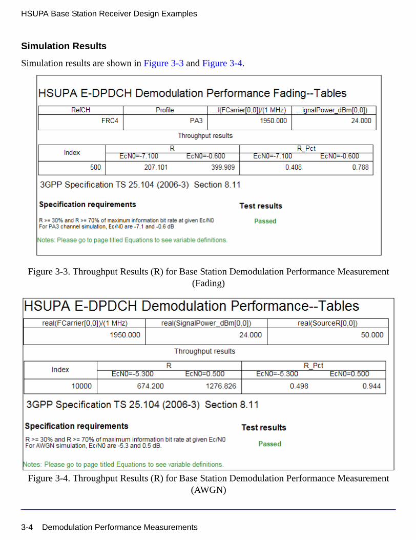
HSUPA Base Station Receiver Design Examples
Simulation Results
Simulation results are shown in Figure 3-3 and Figure 3-4.
Figure 3-3. Throughput Results (R) for Base Station Demodulation Performance Measurement (Fading)
Figure 3-4. Throughput Results (R) for Base Station Demodulation Performance Measurement (AWGN)
3-4 Demodulation Performance Measurements

Benchmark
Simulation time is about 8.3 hours for two sweep points of 500 10ms TTI over fading condition and 4 hours for two sweep points of 10000 2ms TTI over AWGN condition, on a P4/2.6GHz 512MB PC running ADS 2005A on Microsoft Windows 2000.
Demodulation Performance Measurements 3-5

HSUPA Base Station Receiver Design Examples
Signaling Detection Performance Measurements - False AlarmBS_RX_FalseAlarmFading.dsn
BS_RX_FalseAlarm.dsn
Features
• Base station receiver E-DPCCH signaling detection performance measurements
• Uplink fixed reference channel (FRC) and receiver
• Integrated RF models
• Multi-path fading propagation conditions
Description
BS_RX_FalseAlarmFading.dsn measures base station receiver E-DPCCH signaling false alarm performance according to section 8.12 in TS 25.104.
BS_RX_FalseAlarm.dsn measures base station receiver E-DPCCH signaling false alarm performance over AWGN condition to provide the baseline reference.
3-6 Signaling Detection Performance Measurements - False Alarm

The schematics for BS_RX_FalseAlarmFading.dsn and BS_RX_FalseAlarm.dsn are shown in Figure 3-5 and Figure 3-6 respectively.
Figure 3-5. BS_RX_FalseAlarmFading.dsn Schematic
Signaling Detection Performance Measurements - False Alarm 3-7

HSUPA Base Station Receiver Design Examples
.
Figure 3-6. BS_RX_FalseAlarm.dsn Schematic
3-8 Signaling Detection Performance Measurements - False Alarm

Simulation Results
Simulation results are shown in Figure 3-7 and Figure 3-8.
Figure 3-7. False Alarm Results for Base Station Signaling Detection Performance Measurements (Fading)
Signaling Detection Performance Measurements - False Alarm 3-9

HSUPA Base Station Receiver Design Examples
Figure 3-8. False Alarm Results for Base Station Signaling Detection Performance Measurements (AWGN)
Benchmark
Simulation time is about 14.7 hours for 5000 2ms TTI over fading (PB3) condition and 1.5 hours for 10000 2ms TTI over AWGN condition, on a P4/2.6GHz 512MB PC running ADS 2005A on Microsoft Windows 2000.
3-10 Signaling Detection Performance Measurements - False Alarm
Signaling Detection Performance Measurements - Missed DetectionBS_RX_MissedDetectionFading.dsn
BS_RX_MissedDetection.dsn
Features
• Base station receiver E-DPCCH signaling detection performance measurements
• Uplink fixed reference channel (FRC) and receiver
• Integrated RF models
• Multi-path fading propagation conditions
Description
BS_RX_MissedDetectionFading.dsn measures base station receiver E-DPCCH signaling missed detection performance according to section 8.12 in TS 25.104.
BS_RX_MissedDetection.dsn measures base station receiver E-DPCCH signaling missed detection performance over AWGN condition to provide the baseline reference.
Signaling Detection Performance Measurements - Missed Detection 3-11

HSUPA Base Station Receiver Design Examples
The schematics for fading and AWGN conditions are shown in Figure 3-9 and Figure 3-10 respectively.
Figure 3-9. BS_RX_MissedDetectionFading.dsn Schematic
3-12 Signaling Detection Performance Measurements - Missed Detection

Figure 3-10. BS_RX_MissedDetection.dsn Schematic
Signaling Detection Performance Measurements - Missed Detection 3-13

HSUPA Base Station Receiver Design Examples
Simulation Results
Simulation results are shown in Figure 3-11 and Figure 3-12.
Figure 3-11. Missed Detection Results for Base Station Signaling Detection Performance Measurements (Fading)
3-14 Signaling Detection Performance Measurements - Missed Detection

Figure 3-12. Missed Detection Results for Base Station Signaling Detection Performance Measurements (AWGN)
Benchmark
Simulation time is about 15.5 hours for 5000 2ms TTI over fading (PB3) condition and 1.5 hours for 10000 2ms TTI over AWGN condition, on a P4/2.6GHz 512MB PC running ADS 2005A on Microsoft Windows 2000.
Signaling Detection Performance Measurements - Missed Detection 3-15

HSUPA Base Station Receiver Design Examples
3-16 Signaling Detection Performance Measurements - Missed Detection

Chapter 4: HSUPA User Equipment Receiver Design Examples
IntroductionThe HSUPA_UE_Rx_prj project shows user equipment receiver measurement performances, including E-AGCH demodulation performance, E-HICH detection performance, and E-RGCH detection performance.
Designs for these measurements are described in the following sections; they include:
• E-AGCH demodulation performance:
UE_Rx_EAGCH_Demodulation.dsn
UE_Rx_EAGCH_DemodulationFading.dsn
• E-HICH detection performance:
UE_Rx_EHICH_Detection.dsn
UE_Rx_EHICH_DetectionFading.dsn
• E-RGCH detection performance:
UE_Rx_ERGCH_Detection.dsn
UE_Rx_ERGCH_DetectionFading.dsn
Designs under this project consist of:
• Downlink RF band signal source
HSUPA_DL_SourceRF is used to provide an RF HSUPA downlink signal source.
• Fading channel
HSPA_Channel is used to provide various multi-path fading propagation conditions.
• AWGN noise
AddNDensity is used to provide AWGN in order to calibrate the Ec/Ior at certain levels,
which are required by various performance measurements.
• User Equipment RF receiver
HSUPA_DL_ReceiverRF is used to provide a receiver of RF HSUPA downlink signals.
Introduction 4-1
HSUPA User Equipment Receiver Design Examples
References
[1] 3GPP Technical Specification TS 25.101, "UE Radio transmission and Reception (FDD)," Version 6.11.0, Mar. 2006.
E-AGCH Demodulation Performance MeasurementsUE_Rx_EAGCH_DemodulationFading.dsn
UE_Rx_EAGCH_Demodulation.dsn
Features
• User equipment E-AGCH demodulation performance measurements
• Integrated RF models
• Multi-path fading propagation conditions
Description
UE_Rx_EAGCH_DemodulationFading.dsn measures user equipment receiver E-AGCH demodulation performance according to section 10.4.1 in TS 25.101.
UE_Rx_EAGCH_Demodulation.dsn measures user equipment receiver E-AGCH demodulation performance over AWGN condition to provide the baseline reference.
4-2 E-AGCH Demodulation Performance Measurements

The schematics for fading and AWGN conditions are shown in Figure 4-1 and Figure 4-2 respectively.
Figure 4-1. UE_Rx_EAGCH_DemodulationFading.dsn Schematic
Figure 4-2. UE_Rx_EAGCH_Demodulation.dsn Schematic
E-AGCH Demodulation Performance Measurements 4-3

HSUPA User Equipment Receiver Design Examples
Simulation Results
Simulation results are shown in Figure 4-3 and Figure 4-4.
Figure 4-3. User Equipment E-AGCH Demodulation Performance Results (Fading)
Figure 4-4. User Equipment E-AGCH Demodulation Performance Results (AWGN)
4-4 E-AGCH Demodulation Performance Measurements
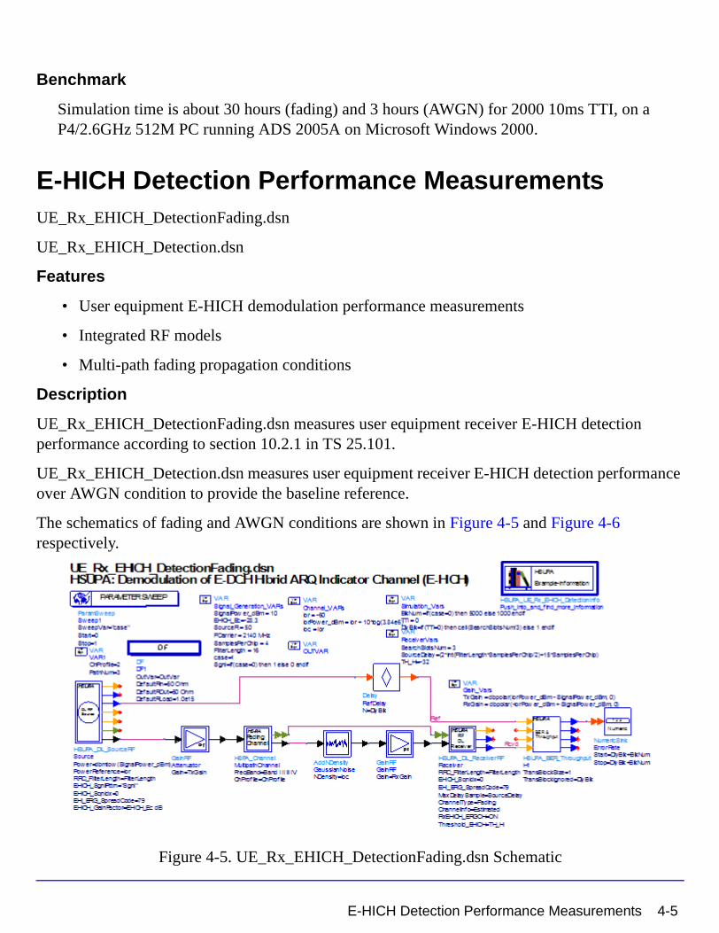
Benchmark
Simulation time is about 30 hours (fading) and 3 hours (AWGN) for 2000 10ms TTI, on a P4/2.6GHz 512M PC running ADS 2005A on Microsoft Windows 2000.
E-HICH Detection Performance MeasurementsUE_Rx_EHICH_DetectionFading.dsn
UE_Rx_EHICH_Detection.dsn
Features
• User equipment E-HICH demodulation performance measurements
• Integrated RF models
• Multi-path fading propagation conditions
Description
UE_Rx_EHICH_DetectionFading.dsn measures user equipment receiver E-HICH detection performance according to section 10.2.1 in TS 25.101.
UE_Rx_EHICH_Detection.dsn measures user equipment receiver E-HICH detection performance over AWGN condition to provide the baseline reference.
The schematics of fading and AWGN conditions are shown in Figure 4-5 and Figure 4-6 respectively.
Figure 4-5. UE_Rx_EHICH_DetectionFading.dsn Schematic
E-HICH Detection Performance Measurements 4-5

HSUPA User Equipment Receiver Design Examples
Figure 4-6. UE_Rx_EHICH_Detection.dsn Schematic
Simulation Results
Simulation results are shown in Figure 4-7 and Figure 4-8.
4-6 E-HICH Detection Performance Measurements

Figure 4-7. User Equipment E-HICH Detection Performance Results (Fading)
E-HICH Detection Performance Measurements 4-7

HSUPA User Equipment Receiver Design Examples
Figure 4-8. User Equipment E-HICH Detection Performance Results (AWGN)
Benchmark
Simulation time is about 9.7 hours (fading, VA30) and 3 hours (AWGN) for 11000 2ms TTI, on a P4/2.6GHz 512MB PC running ADS 2005A on Microsoft Windows 2000.
4-8 E-HICH Detection Performance Measurements

E-RGCH Detection Performance MeasurementsUE_Rx_ERGCH_Detection.dsn
UE_Rx_ERGCH_DetectionFading.dsn
Features
• User equipment E-RGCH demodulation performance measurements
• Integrated RF models
• Multi-path fading propagation conditions
Description
UE_Rx_ERGCH_DetectionFading.dsn measures user equipment receiver E-RGCH detection performance according to section 10.3.1 in TS 25.101.
UE_Rx_ERGCH_Detection.dsn measures user equipment receiver E-RGCH detection performance over AWGN condition to provide the baseline reference.
The schematics for fading and AWGN conditions are shown in Figure 4-9 and Figure 4-10.
Figure 4-9. UE_Rx_ERGCH_DetectionFading.dsn Schematic
E-RGCH Detection Performance Measurements 4-9

HSUPA User Equipment Receiver Design Examples
Figure 4-10. UE_Rx_ERGCH_Detection.dsn Schematic
4-10 E-RGCH Detection Performance Measurements

Simulation Results
Simulation results are shown in Figure 4-11 and Figure 4-12.
Figure 4-11. User Equipment E-RGCH Detection Performance Results (Fading)
E-RGCH Detection Performance Measurements 4-11

HSUPA User Equipment Receiver Design Examples
Figure 4-12. User Equipment E-RGCH Detection Performance Results (AWGN)
Benchmark
Simulation time is about 10 hours (fading) and 1.5 hours (AWGN) for 6000 2ms TTI, on a P4/2.6GHz 512MB PC running ADS 2005A on Microsoft Windows 2000.
4-12 E-RGCH Detection Performance Measurements

Chapter 5: HSUPA User Equipment Transmitter Design Examples
IntroductionThe HSUPA_UE_Tx_prj project shows user equipment transmitter measurement characteristics, including adjacent channel leakage power ratio (ACLR), complementary cumulative distribution function (CCDF), error vector magnitude (EVM), maximum power, and spectrum emission mask.
Designs for these measurements are described in the following sections; they include:
• Adjacent channel leakage power ratio measurements: UE_Tx_ACLR.dsn
• CCDF and peak-to-mean information measurements: UE_Tx_CCDF.dsn
• Error vector magnitude measurements: UE_Tx_EVM.dsn
• Maximum power measurements: UE_Tx_Max_Power.dsn
• Spectrum emission mask measurements: UE_Tx_SpecEmissions.dsn
HSUPA_UL_SourceRF is used to provide an RF HSUPA uplink signal source for the designs under this project.
References
[1] 3GPP Technical Specification TS 25.101, "UE Radio transmission and Reception (FDD)," Version 6.11.0, Mar. 2006.
Introduction 5-1

HSUPA User Equipment Transmitter Design Examples
Adjacent Channel Leakage Power Ratio MeasurementsUE_Tx_ACLR.dsn
Features
• HSUPA uplink RF signal source
• signal source including DPCCH, DPDCH, E-DPCCH, E-DPDCH, and HSDPCCH
• power in an adjacent channel measured using FFT
Description
This design measures user equipment transmitter adjacent channel leakage power ratio (ACLR) characteristics according to section 6.6.2.2 in TS 25.101.
ACLR is the ratio of the transmitted power to the power measured in an adjacent channel. Both the transmitted power and the adjacent channel power are measured with a filter that has a root-raised cosine (RRC) filter response with a rolloff of 0.22 and a bandwidth equal to the chip rate.
Frequency domain power in 4 adjacent channels is measured: 2 above and 2 below the center frequency of the measured signal.
The schematic is shown in Figure 5-1. 3GPPFDD_RF_ACLR is used to measure output power.
5-2 Adjacent Channel Leakage Power Ratio Measurements

Figure 5-1. UE_Tx_ACLR.dsn Schematic
Adjacent Channel Leakage Power Ratio Measurements 5-3

HSUPA User Equipment Transmitter Design Examples
Simulation Results
Simulation results are shown in Figure 5-2 and Figure 5-3.
Figure 5-2. User Equipment ACLR Measurement Results - Tables
5-4 Adjacent Channel Leakage Power Ratio Measurements

Figure 5-3. User Equipment ACLR Measurement Results - Figures
Benchmark
Simulation time is about 12 seconds on a Pentium M/1.6GHz 1024MB PC running ADS 2005A on Microsoft Windows XP.
Adjacent Channel Leakage Power Ratio Measurements 5-5
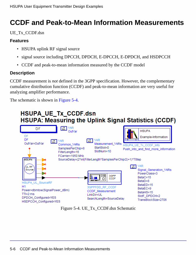
HSUPA User Equipment Transmitter Design Examples
CCDF and Peak-to-Mean Information MeasurementsUE_Tx_CCDF.dsn
Features
• HSUPA uplink RF signal source
• signal source including DPCCH, DPDCH, E-DPCCH, E-DPDCH, and HSDPCCH
• CCDF and peak-to-mean information measured by the CCDF model
Description
CCDF measurement is not defined in the 3GPP specification. However, the complementary cumulative distribution function (CCDF) and peak-to-mean information are very useful for analyzing amplifier performance.
The schematic is shown in Figure 5-4.
Figure 5-4. UE_Tx_CCDF.dsn Schematic
5-6 CCDF and Peak-to-Mean Information Measurements

Simulation Results
Simulation results are shown in Figure 5-5 and Figure 5-6.
Figure 5-5. User Equipment CCDF Measurement Results - Tables
CCDF and Peak-to-Mean Information Measurements 5-7

HSUPA User Equipment Transmitter Design Examples
Figure 5-6. User Equipment CCDF Measurement Results - Figures
Benchmark
Simulation time is about 3 seconds on a Pentium M/1.6GHz 1024MB PC running ADS 2005A on Microsoft Windows XP.
5-8 CCDF and Peak-to-Mean Information Measurements

Error Vector Magnitude MeasurementsUE_Tx_EVM.dsn
Features
• HSUPA uplink RF signal source
• signal source including DPCCH, DPDCH, E-DPCCH, E-DPDCH, and HSDPCCH
• error vector magnitude is measured by the EVM model
• phase discontinuity is measured by the EVM model
• reference signal is used
Description
This design measures user equipment transmitter error vector magnitude (EVM) and phase discontinuity characteristics according to section 6.8.2 and 6.8.4 in TS 25.101 respectively.
EVM is a measure of the difference between the measured waveform and the theoretical modulated waveform (the error vector). It is the square root of the ratio of the mean error vector power to the mean reference signal power expressed as a percentage.
For Release 99 and Release 4, the EVM measurement interval is one timeslot. For Release 5 and later releases where tests may include power changes, the measurement interval is further clarified as being one timeslot except when the mean power between slots is expected to change whereupon the measurement interval is reduced by 25 µs at each end of the slot.
The phase discontinuity is always made in the measurement interval of one timeslot reduced by 25 µs at each end of the slot, then extrapolated in both directions onto the timeslot boundaries.
The schematic is shown in Figure 5-7.
Error Vector Magnitude Measurements 5-9

HSUPA User Equipment Transmitter Design Examples
Figure 5-7. UE_Tx_EVM.dsn Schematic
5-10 Error Vector Magnitude Measurements

Simulation Results
Simulation results are shown in Figure 5-8.
Figure 5-8. User Equipment EVM Measurement Results
Benchmark
Simulation time is about 30 seconds on a Pentium M/1.6GHz 1024MB PC running ADS 2005A on Microsoft Windows XP.
Error Vector Magnitude Measurements 5-11

HSUPA User Equipment Transmitter Design Examples
Maximum Power MeasurementsUE_Tx_Max_Power.dsn
Features
• HSUPA uplink RF signal source
• signal source including DPCCH, DPDCH, E-DPCCH, E-DPDCH, and HSDPCCH
• output power is measured by the HSUPA RF output power model
Description
This design measures user equipment transmitter maximum output power characteristics according to section 6.2.2 in TS 25.101.
The schematic is shown in Figure 5-9.
Figure 5-9. UE_Tx_Max_Power.dsn Schematic
5-12 Maximum Power Measurements
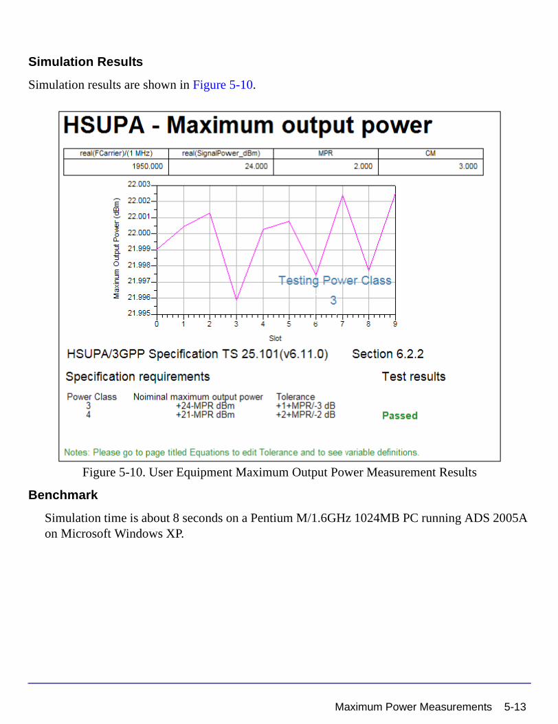
Simulation Results
Simulation results are shown in Figure 5-10.
Figure 5-10. User Equipment Maximum Output Power Measurement Results
Benchmark
Simulation time is about 8 seconds on a Pentium M/1.6GHz 1024MB PC running ADS 2005A on Microsoft Windows XP.
Maximum Power Measurements 5-13

HSUPA User Equipment Transmitter Design Examples
Spectrum Emission Mask MeasurementsUE_Tx_SpecEmissions.dsn
Features
• HSUPA uplink RF signal source
• signal source including DPCCH, DPDCH, E-DPCCH, E-DPDCH, and HSDPCCH
• ParamSweep and SweepPlan is used
Description
This design measures user equipment transmitter out-of-band emission characteristics according to section 6.6.2.1 in TS 25.101.
The spectrum emission mask of the UE applies to frequencies, which are between 2.5 MHz and 12.5 MHz away from the UE center carrier frequency. The out of channel emission is specified relative to the RRC filtered mean power of the UE carrier.
The schematic is shown in Figure 5-11.
5-14 Spectrum Emission Mask Measurements

Figure 5-11. UE_Tx_SpecEmissions.dsn Schematic
Spectrum Emission Mask Measurements 5-15

HSUPA User Equipment Transmitter Design Examples
Simulation Results
Simulation results are shown in Figure 5-12.
Figure 5-12. User Equipment Spectrum Emission Mask Measurement Results
Benchmark
Simulation time is about 25 minutes on a Pentium M/1.6GHz 1024MB PC running ADS 2005A on Microsoft Windows XP.
5-16 Spectrum Emission Mask Measurements

Index
Numerics3GPP Technical Specifications Supported,1-1
Aadjacent channel leakage power ratio
measurements, 5-2
CCCDF measurements, 5-6
Eerror vector magnitude measurements, 5-9
HHSPA_Channel, 2-2HSUPA_BER_Throughput, 2-7HSUPA_Bits, 2-10HSUPA_ChDecode, 2-13HSUPA_ChEncode, 2-15HSUPA_CodeBlkDeseg, 2-17HSUPA_CodeBlkSeg, 2-19HSUPA_Deinterleaver, 2-21HSUPA_DL_Rake, 2-23HSUPA_DL_Receiver, 2-28HSUPA_DL_ReceiverRF, 2-33HSUPA_DL_Source, 2-38HSUPA_DL_SourceRF, 2-45HSUPA_EAGCH, 2-54HSUPA_EAGCH_Decode, 2-58HSUPA_EAGCH_DeRM, 2-60HSUPA_EAGCH_RM, 2-62HSUPA_EDPCCH_ChDecode, 2-64HSUPA_EDPCCH_ChEncode, 2-66HSUPA_EHICH_ERGCH, 2-68HSUPA_EHICH_ERGCH_Decode, 2-70HSUPA_EVM, 2-73HSUPA_FRC_Receiver, 2-76, 2-79HSUPA_FRC_ReceiverRF, 2-83HSUPA_FRC_RF, 2-87HSUPA_Interleaver, 2-90HSUPA_OCNS, 2-92HSUPA_ParamCalc, 2-95, 2-107HSUPA_PhCH_Demap, 2-97HSUPA_PhCH_Map, 2-99HSUPA_RateDematch, 2-101
HSUPA_RateMatch, 2-104HSUPA_RF_OutputPower, 2-111, 2-114HSUPA_Spread, 2-119HSUPA_UL_Rake, 2-123HSUPA_UL_Source, 2-130HSUPA_UL_SourceRF, 2-133
Mmaximum power measurements, 5-12measurements
adjacent channel leakage power ratio measurements, 5-2
CCDF, 5-6error vector magnitude, 5-9maximum power, 5-12peak-to-mean, 5-6spectrum emission mask, 5-14
Ppeak-to-mean information measurements,
5-6
Sspectrum emission mask measurements, 5-
14supported specifications, 1-1
Index-1

Index-2