hst - cosmic origins spectrograph assembly, integration… · hst - cosmic origins spectrograph...
TRANSCRIPT

HST - Cosmic Origins Spectrograph Assembly, Integration, and Verification Overview
NUVA Challenges in UV Astronomy 2013
Page 1
Kevin France – University of Colorado
co-authors: James C Green – PI
Cynthia S Froning – Project Scientist

Outline • COS Introduction – mostly covered in science talks • Component- and system-level testing at University of Colorado • Thermal Vac: Ball Aerospace and Goddard Space Flight Center • Alignment verification, sensitivity tracking, and light leak checks • Contamination control, contamination control, contamination ….
Note: don’t worry about the acronyms
COS Overview
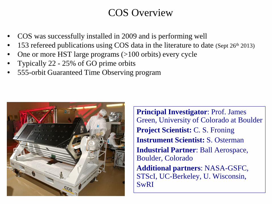
• COS was successfully installed in 2009 and is performing well • 153 refereed publications using COS data in the literature to date (Sept 26th 2013) • One or more HST large programs (>100 orbits) every cycle • Typically 22 - 25% of GO prime orbits • 555-orbit Guaranteed Time Observing program
Principal Investigator: Prof. James Green, University of Colorado at Boulder Project Scientist: C. S. Froning Instrument Scientist: S. Osterman Industrial Partner: Ball Aerospace, Boulder, Colorado Additional partners: NASA-GSFC, STScI, UC-Berkeley, U. Wisconsin, SwRI

The low-z Intergalactic Medium • Missing baryons in the local universe • Large scale structure • Galaxy formation and evolution • Feedback: galaxy-IGM interactions
Millennium Run

The low-z Intergalactic Medium • Missing baryons in the local universe • Large scale structure • Galaxy formation and evolution • Feedback: galaxy-IGM interactions
•Increased number of known IGM absorbers by factor of ~50 over all the systems observed by HST prior to 2009 • Weak IGM absorber density evolving faster than strong absorbers associated with galactic outflows
• 2500 IGM absorption systems •300 OVI systems •100 CIII and SiIII systems •18 NeVIII systems
Danforth et al. (ApJ – 2014 in prep)
Weak Abs
Strong Abs

Exoplanet Atmospheres: Gas Giants
• 1.5 % Geometric Occultation
•7.8 ± 1.3% CII 1335Å Occultation
• 8.2 ± 1.4% SiIII 1206Å Occultation
•(0.2 ± 1.4 % SiIV 1394Å Occultation)
Si2+ C+
Linsky et al. 2010

Typical (t < 10 Myr) protoplanetary
disk
Protoplanetary Disks

Typical (t < 10 Myr) protoplanetary
disk
Protoplanetary Disks

Molecules in Protoplanetary Disks: Ultraviolet Emission from the Inner Disk
A wealth of resolved H2 and CO emission and absorption features
Ardila et al. (ApJ – 2013) France et al. (ApJ – 2010) France et al. (ApJ - 2011a,b) France et al. (ApJ - 2012a,b) France et al. (ApJ – 2013 submitted) Ingleby et al. (ApJ – 2011) McJunkin, France et al. (ApJ – 2013a,b) Schindhelm, France et al. (ApJ/L – 2012a,b) Schneider et al. (A&A – 2013 in prep) Woitke et al. (A&A - 2011)

Cosmic Origins Spectrograph

COS Instrument
MEB & LVPS RIU DEB
Aperture Mechanism
Optics Select Mechanism - 1
Optics Select Mechanism - 2
FUV Detector 1150-1775A
Cal Platform
NUV Detector 1750-3200A

• COS has 2 channels to provide low and medium resolution UV spectroscopy
– FUV: 800-1775Å, NUV: 1700-3200Å • FUV gratings: G130M, G160M, G140L • NUV gratings: G185M, G225M, G285M, G230L
– M gratings have spectral resolution of R ~ (17 – 20) × 103
NUV MAMA Detector
(STIS spare)
Calibration Platform
FUV XDL Detector
OSM2: G185M, G225M, G285M, G230L, TA1
OSM1: G130M, G160M, G140L, NCM1
Aperture Mechanism: Primary Science Aperture, Bright Object Aperture
Optical bench (not shown):
re-use of GHRS bench
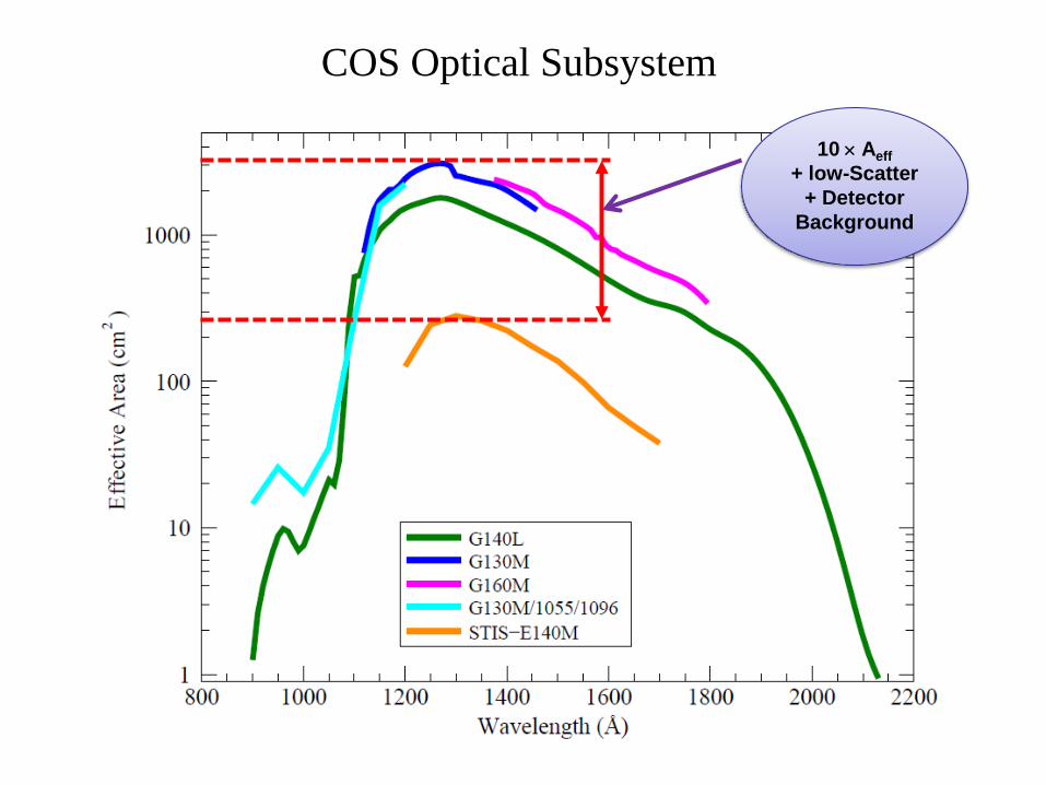
COS Optical Subsystem
COS Optical Subsystem
10 × Aeff + low-Scatter
+ Detector Background

COS Optical Bench & Enclosure
• Original GHRS Optical Bench was modified and refurbished
• The graphite epoxy material for the structural members and laminates that were added to the original GHRS bench are identical to those found in COSTAR and STIS
• Graphite epoxy honeycomb panels (aluminum honeycomb core and graphite epoxy face sheets), tubes, and sheet

Cosmic Origins Spectrograph
Initial Testing & Assembly

Cosmic Origins Spectrograph • Square tank facilities for component-level testing

Cosmic Origins Spectrograph • CASA FUV/EUV Optics Test Facility, 11’ diameter, 14’ long

Cosmic Origins Spectrograph • CASA FUV/EUV Optics Test Facility

Cosmic Origins Spectrograph • CASA FUV/EUV Optics Test Facility

Cosmic Origins Spectrograph
System Level Test Results

COS Thermal Balance and Thermal
Vacuum
Page 21
Cosmic Origins Spectrograph

COS Thermal Balance and Thermal
Vacuum
Page 22
Cosmic Origins Spectrograph

• Objectives – Demonstrate COS robustness by functional testing the flight
system in thermal environments in excess of flight predictions – Verify alignment and performance of the FUV and NUV
science channels – Verify that COS meets the HST outgassing rate (4.3E-13
g/cm2/sec at +30C/–20C)
• Goals of thermal balance test: – Demonstrate operation of the COS thermal control systems – Validate and correlate the COS thermal math model (TMM)
Objectives and Goals

ID Test Activity Begin (Eastern) ID Test Activity Begin (Eastern)
1 Chamber Pump Down 11/11/06 14:25 10a Hot Thermal Balance #2, Side 1;Transition to Hot TV 11/23/06 21:502 Alignment Check 11/14/06 8:30 10 Hot Thermal Vac Cycle #2, COS Functional Test 11/24/06 2:003 Cold Safe Thermal Balance 11/16/06 8:15 11 Transition to Cold Thermal Vacuum 11/25/06 2:00
4 Cold Operate Thermal Balance 11/17/06 15:20 12 Cold Thermal Vac Cycle #2, COS Functional Test and Side 1 Cold Start
11/25/06 14:00
5 Hot Operate Thermal Balance #1, Side 2 11/18/06 14:00 13 Transition to Calibration Plateau 11/26/06 10:556 Hot Thermal Vac Cycle #1, COS Functional Test 11/19/06 13:00 14a Pre-Cal Alignment Check 11/27/06 8:157 Transition to Cold Thermal Vacuum 11/21/06 8:30 14 Science Calibration 11/28/06 0:05
8 Cold Thermal Vac Cycle #1, COS Functional Test and Side 2 Cold Start
11/21/06 20:00 15 Contamination Certification 12/8/06 1:07
9 Transition to Hot Operate Thermal Balance 11/22/06 21:30 16 Return to Ambient and Chamber Break 12/8/06 20:42
Time (Not to Scale)
Tem
pera
ture
(Not
to S
cale
)
1 2
3 4
5
6
7
8
9
10
11
12
13
14 15
16
10a
COS Thermal Vacuum Test 2006 Summary

2006 Thermal Balance Test Results
• All temperature data points correlated to within 5°C – Success criterion was defined to be within 5°C – Fewer than 7% were more than 3°C different
• All subassemblies remained within limits • All heaters met their performance requirements
COS Thermal Balance Fixture(TBF)
RAS/CAL
Relay Optics
CDS Enclosure
Baseplate Assembly
Vibration IsolationTable (VIS)
Payload Table
COS Thermal Balance Fixture(TBF)
RAS/CAL
Relay Optics
CDS Enclosure
Baseplate Assembly
Vibration IsolationTable (VIS)
Payload Table
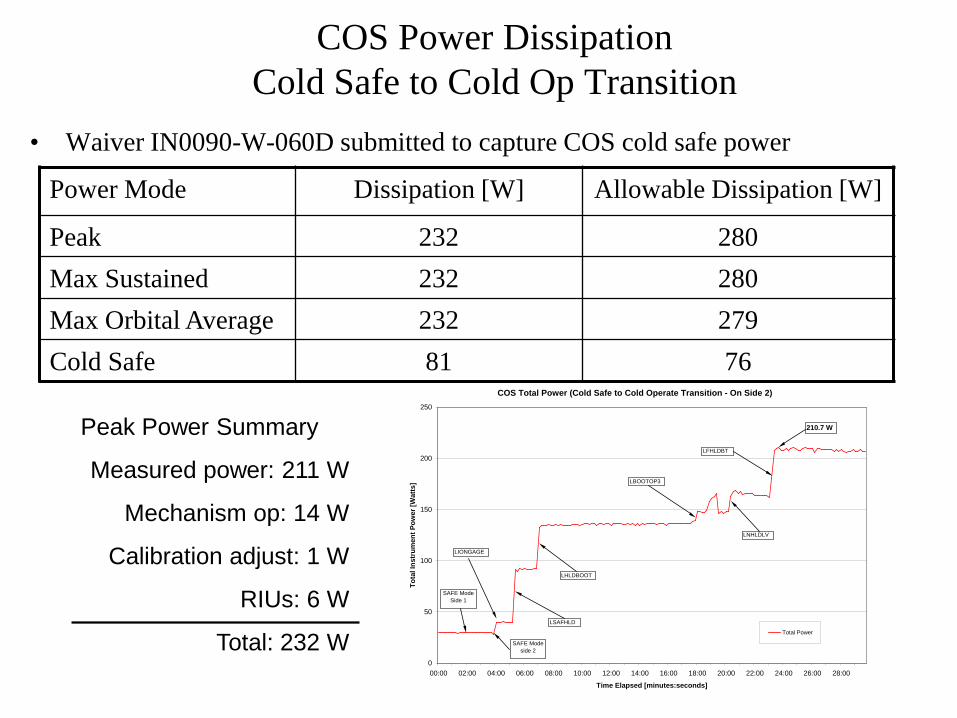
COS Power Dissipation Cold Safe to Cold Op Transition
• Waiver IN0090-W-060D submitted to capture COS cold safe power
COS Total Power (Cold Safe to Cold Operate Transition - On Side 2)
0
50
100
150
200
250
00:00 02:00 04:00 06:00 08:00 10:00 12:00 14:00 16:00 18:00 20:00 22:00 24:00 26:00 28:00
Time Elapsed [minutes:seconds]
Tota
l Ins
trum
ent P
ower
[Wat
ts]
Total Power
SAFE ModeSide 1
LIONGAGE
LSAFHLD
LHLDBOOT
LBOOTOP3
LNHLDLV
LFHLDBT
SAFE Modeside 2
210.7 W
Power Mode Dissipation [W] Allowable Dissipation [W]
Peak 232 280 Max Sustained 232 280 Max Orbital Average 232 279 Cold Safe 81 76
Peak Power Summary
Measured power: 211 W
Mechanism op: 14 W
Calibration adjust: 1 W
RIUs: 6 W
Total: 232 W

Science Calibration
Cosmic Origins Spectrograph

Detector Calibration

Calibration Delivery System - 2006
• TV was moved from BATC to GSFC in 2006.
• The larger vacuum chamber at Goddard required a new vacuum-compatible CDS.
• The new CDS was mounted on the same table as RASCAL and COS (improved alignment).

Calibration Delivery System - 2006

Spectrograph Sensitivity
Cosmic Origins Spectrograph

G130M
0.00
0.05
0.10
0.15
0.20
1100 1200 1300 1400 1500Wavelength Angstroms
Cou
nts
per P
hoto
n
CEI min
CEI max
2003 data2006 data
G160M
0.00
0.04
0.08
0.12
1400 1500 1600 1700 1800Wavelength Angstroms
Cou
nts
per P
hoto
n 2003 data
CEI min
CEI max
2006 data
G140L
0.000.020.040.060.080.100.120.14
1200 1300 1400 1500 1600 1700 1800
Wavelength Angstroms
Cou
nts
per P
hoto
n
CEI min
CEI max
2003 data2006 data
Thermal Vacuum Sensitivity Calibration Results: COS FUV Channels
• All FUV channels meet CEI sensitivity requirements.

Apparent COS Performance Changes from 2003 to 2006
• G130M & G140L, changes in 2003/2006 measurements are the result of changes in CDS polarization content and do not reflect changes in COS performance.
• G225M and G285M changes are consistent a combined polarization effect plus real loss.
-40.0%
-30.0%
-20.0%
-10.0%
0.0%
10.0%
20.0%
30.0%
40.0%
50.0%
1100 1600 2100 2600 3100
Wavelength
% C
hang
e 20
03 t
o 20
06
TA1G230LG185MG225MG285MG130MG160MG140L
Great news, the sensitivity increases with time!

NUV Grating Monitoring
• G185M showed no change in performance relative to G230L (both coated aluminum gratings)
• G225M and G285M (bare aluminum) showed a consistent decrease with time.

Current Best Explanation for Changes in Performance
• What is not causing the change in performance – Not hydrocarbon contamination
• Conventional hydrocarbon contamination would be apparent in witness coupon reflectivity – no change.
• Resonance effect of thin layer would not impact reflectivity, but no significant buildup apparent in XPS testing of coupons or spare gratings
– Not metal migration in reflective coating • No impact on reflectivity (witness coupons) • No Au apparent in XPS testing
– Not test setup polarization bias • Direct testing of GSE showed no polarization at λ > 2200Å
• A thin oxide layer (5-10nm) will impact sensitivity to polarized light as a function of wavelength in high ruling density gratings while not changing witness coupon reflectivity - Modeled performance changes are consistent with observed performance of G225M and G285M

Cosmic Origins Spectrograph
Alignment Verification

Alignment Overview
• COS alignment verified
– Thermal Vacuum 2006 • Stimulus (RASCAL) aligned to cubes on COS optical
bench – COS installed in Thermal Balance Fixture
• Thermal Balance fixture had alignment stability issues – When chamber went cold, structure shrunk
» Same issue in 2003 testing – Results in misalignment of stimulus relative to COS – Structure stabilized to 5 C – ~ 47 arcsec of angular motion
» reasonable given temperature gradient » Small image quality degradation
• Verified pre and post acoustics

Thermal Vacuum - FUV
• 2006 Thermal Vacuum Test shows FUV meets Resolution Requirement – G130 shown here
Meets requirement
R ≥ 20,000

Enclosure Light Leak Test
Cosmic Origins Spectrograph

Enclosure Light Leak Test
• NUV detector image during dark rate testing

Light Leak Fix
Black Kapton Staking Dots

Before and After Images
After Fix Before Fix
• Enclosure now light tight

Cosmic Origins Spectrograph
Contamination

Surface Cleanliness • Requirement: Level 400B per MIL-STD 1246B • Measurement:
• To be verified by tapelift and NVR swab sampling at KSC, just prior to ASIPE integration.
• Preliminary tapelifts taken after Crew Fam #4 (5/4/08) indicate current cleanliness of Level 250
• Mitigation: constant vigilance to maintain VCHS
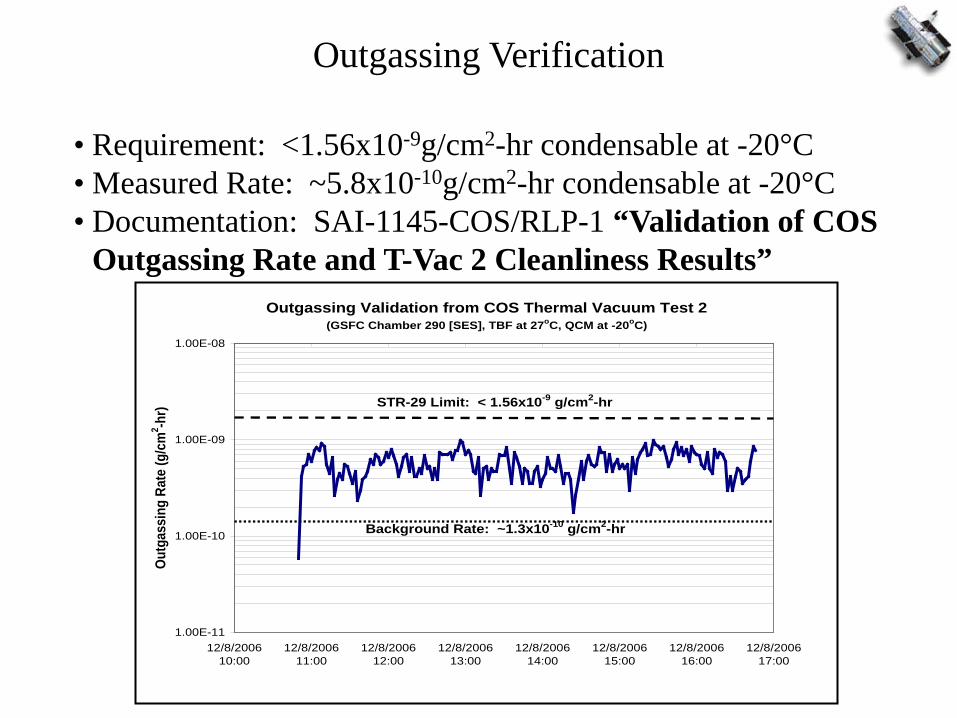
Outgassing Verification
• Requirement: <1.56x10⁻⁹g/cm2-hr condensable at -20°C • Measured Rate: ~5.8x10⁻¹⁰g/cm2-hr condensable at -20°C • Documentation: SAI-1145-COS/RLP-1 “Validation of COS
Outgassing Rate and T-Vac 2 Cleanliness Results” Outgassing Validation from COS Thermal Vacuum Test 2
(GSFC Chamber 290 [SES], TBF at 27oC, QCM at -20oC)
1.00E-11
1.00E-10
1.00E-09
1.00E-08
12/8/200610:00
12/8/200611:00
12/8/200612:00
12/8/200613:00
12/8/200614:00
12/8/200615:00
12/8/200616:00
12/8/200617:00
Outg
assi
ng R
ate
(g/c
m2 -h
r) STR-29 Limit: < 1.56x10⁻⁹ g/cm2-hr
Background Rate: ~1.3x10⁻¹⁰ g/cm2-hr

General Contamination Controls
• COS may only be exposed in a Class 10,000 (FED-STD-209) or better environment
• COS remains purged whenever possible • GN2 Purge disconnect not to exceed 60 minutes per 24 hours • Ion Pump GSE disconnect not to exceed 240 minutes per 24 hours

Cosmic Origins Spectrograph
Transportation (read – contamination II)
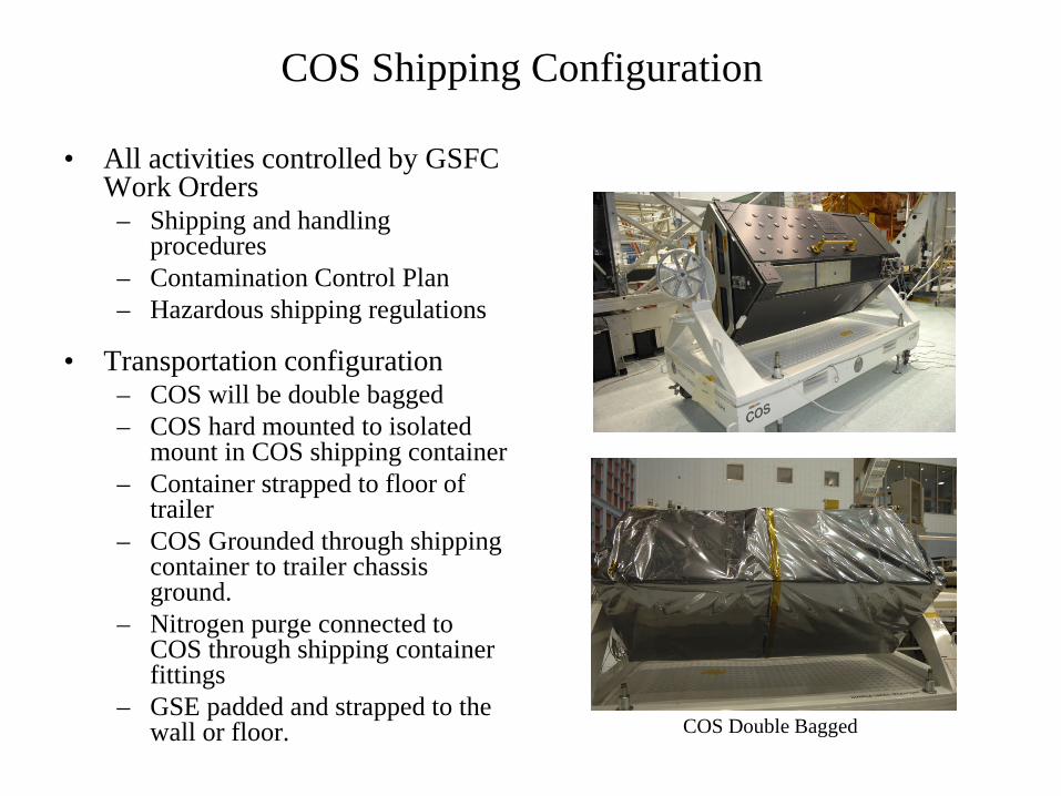
COS Shipping Configuration
• All activities controlled by GSFC Work Orders – Shipping and handling
procedures – Contamination Control Plan – Hazardous shipping regulations
• Transportation configuration – COS will be double bagged – COS hard mounted to isolated
mount in COS shipping container – Container strapped to floor of
trailer – COS Grounded through shipping
container to trailer chassis ground.
– Nitrogen purge connected to COS through shipping container fittings
– GSE padded and strapped to the wall or floor.
COS Double Bagged
COS ready for Double Bagging

Shipping Configuration
COS Ion pump/Purge/Electrical Feed through
Instrument Closeout for shipment COS Container Close up
COS Ready to Ship

GN2 purge requirements for transportation
• Purge through fitting penetrating the container
• 10-15 cu ft per hour • Supply: 8 “A” bottles
manifolded together on purge cart
• Approximately an 8 day supply
• Ion pump GSE will be connected through the shipping container connector plate and connected to COS
• The GSE has a battery pack last between 8-10 hours
• The Ion Pump GSE will be checked at every stop
• The battery pack will be recharged at every fuel stop in route using a Honda 4000 generator (1 hour).
8-Bottle Purge Cart and Panel
Ion Pump GSE

Truck/Trailer
• Air ride rear suspension • Radio communication with lead vehicle • Two drivers, 24 hour service
– English speaking, US citizens • Fully enclosed
– 12’ side doors – 102” wide w/ swing doors – Bullring tie downs in floor – tie down straps and dunnage supplied with trailer
• Air ride suspension • Climatic control • Temperature 65 to 75°F • Humidity control: NTE 50% RH • Honda Generator • Van delivered one day prior to trip, instrumented, and qualified by driving
preplanned course • Trailer held after qualification at GSFC
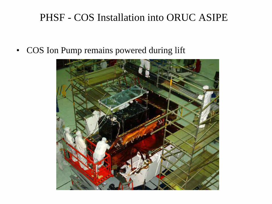
PHSF - COS Installation into ORUC ASIPE
• COS Ion Pump remains powered during lift

COS Connector Panel
8”x8” Access Hole
COS Ion Pump Access
• Axial Scientific Protective Enclosure (ASIPE) lid accommodates two IPGSE lines from COS
ASIPE

COS Installation

Can IPGSE Logistics
Canister Rotation

Can IPGSE Logistics Canister Rollout

Can IPGSE Logistics
Canister Rotation Canister Hoist at Pad

COS Installation

Cosmic Origins Spectrograph
LAUNCH: May 11, 2009
STS-125 / Atlantis
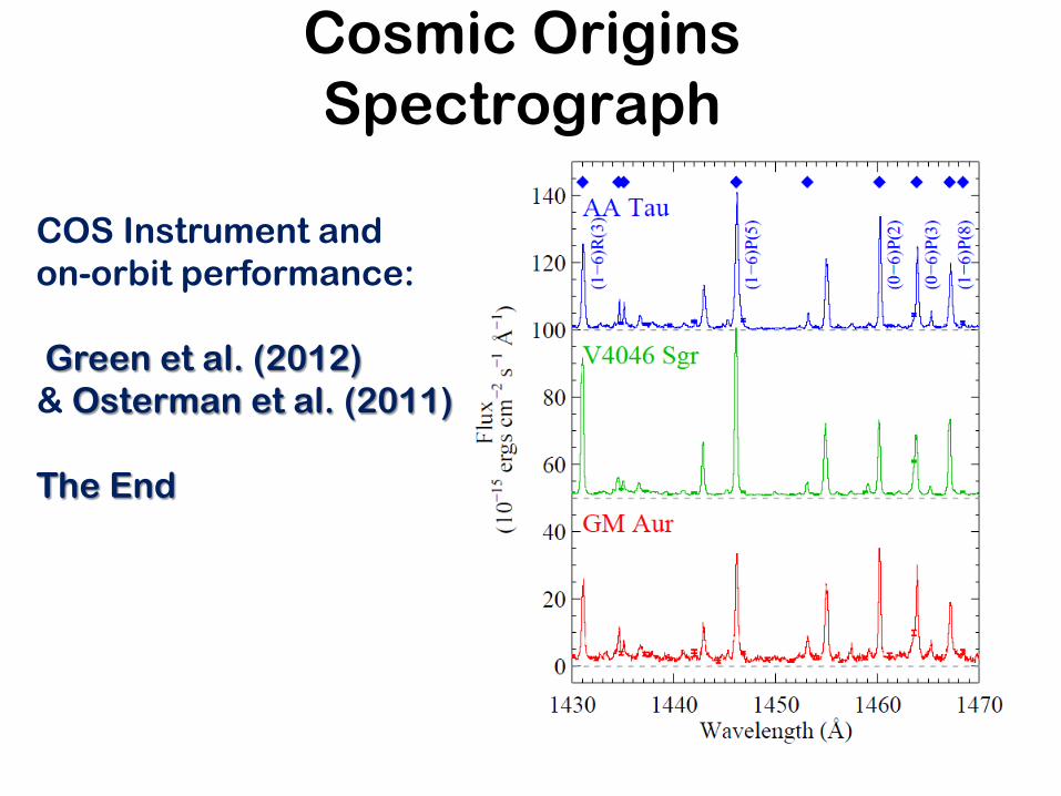
Cosmic Origins Spectrograph
COS Instrument and on-orbit performance: Green et al. (2012) & Osterman et al. (2011) The End