hspa systems architecture and protocols
TRANSCRIPT
1
DAY 2
HSPA Systems Architecture
and Protocols
LTE Basic Reference Model
UE: User Equipment
S-GW: Serving Gateway
P-GW: PDN Gateway
MME : Mobility Management Entity
eNB: evolved Node B
HSS: Home Subscriber Server
2
LTE Basic Reference Model
PCRF: Policy Control and Charging
Rule Function
IMS: IP Multimedia Subsystem
EPC: Evolved packet Core
SAE: System Architecture Evolution
LTE: Long-Term Evolution
EPS: Evolved Packet System
3
User Equipment (UE)
Access device for user.
Provides measurements that indicate
channel conditions to the network
4
eNodeB (1/3)
Hosts PHYsical (PHY), Medium Access
Control (MAC), Radio Link Control
(RLC), and Packet Data Convergence
Protocol (PDCP) layers.
Controls user-plane header-compression
and encryption.
Provides Radio Resource Control (RRC)
functionality for the control plane.
5
eNodeB (2/3)
Functions include :
◦ radio resource management,
◦ admission control,
◦ scheduling, enforcement of negotiated uplink
QoS,
◦ cell information broadcast,
◦ ciphering/deciphering of user and control
plane data, and
◦ compression and decompression of downlink
and uplink user-plane packet headers.
6

eNodeB (3/3)
Cell control and MME pool support
Mobility control
Control and User Plane security
Shared Channel handling
Packet Segmentation/Concatenation
HARQ
Scheduling
Multiplexing and Mapping.
Physical layer functionality Measurements and reporting
Automated operation and maintenance
7
Serving Gateway (S-GW)
Routes and forwards user data packets.
Acts as the mobility anchor for the user plane
during inter-eNB handovers and as the anchor
for mobility between LTE and other 3GPP
technologies.
Terminates the downlink data path for idle state
UEs and triggers paging when DL data arrives
for the UE.
Manages and stores UE contexts, e.g.
◦ parameters of the IP bearer service and network
internal routing inform
8
PDN Gateway (P-GW)
Provides connectivity between the UE and
external packet data networks (PDNs) by being
the point of exit and entry for UE traffic (A UE
may have simultaneous connectivity with more
than one P-GW for accessing multiple PDNs).
Performs policy enforcement, packet filtering
for each user, charging support, lawful
Interception, and packet screening.
Acts as the anchor for mobility between 3GPP
and non- 3GPP technologies such as WiMAX
and 3GPP2 (CDMA 1X and EvDO).
9
MME (Mobility Management Entity) 1/2
The key control node for the LTE network.
Responsible for idle mode UE tracking and
paging procedure including retransmissions.
Controls bearer activation/deactivation process.
Chooses the Serving Gateway (S-GW) for a UE
at initial attachment and at the time of intra-LTE
handover.
Authenticates the user by interacting with the
Home Subscriber Server (HSS).
10

MME (Mobility Management Entity) (2/2)
The termination point for the Non-Access
Stratum (NAS) signaling.
NAS signaling is responsible for generation and
allocation of temporary identities to UEs and
checks the authorization of the UE to camp on
the system.
The termination point for ciphering and
integrity protection for NAS signaling.
Handles security key management.
Controls plane function for mobility between
LTE and other access networks.
11

Policy and Charging Role Function
The Policy and Charging Rules Function (PCRF):
◦ A policy decision point for policy and charging
control of service data flows and IP bearer
resources.
◦ Selects and provides the applicable policy and
charging control decision to the PCEF (i.e. P-
GW).
◦ The policy and charging control element.
12
Policy and Charging Role Function
A single logical PCRF entity may be
deployed by means of multiple and
separately addressable PCRFs in the
PLMN.
In this case, the PCRF discovery and
selection is enabled by Diameter
Routing Agency (DRA).
More detail in TS 23.203 [73].
13
Home Subscriber Server
The HSS is already introduced by UMTS release 5.
With LTE/SAE the HSS will get additionally data per
subscriber for SAE mobility and service handling.
Some changes in the database as well as in the HSS
protocol (DIAMETER) will be necessary to enable HSS
for LTE/SAE.
The HSS can be accessed by the MME via S6a interface.
The HSS is the permanent and central subscriber
database;
◦ stores mobility and service data for every subscriber, and
◦ contains the Authentication Center (AuC) functionality.
14
LTE-U Interface
Air interface of EUTRAN
Based on OFDMA in downlink and SC-
FDMA in uplink
FDD and TDD duplex methods
Scalable bandwidth 1.4MHz to 20 MHz
Data rates up to 100 Mbps in DL
MIMO (Multiple Input Multiple Output)
15
X2 Interface
Inter eNB interface
Handover coordination without involving
the EPC
X2AP: special signalling protocol
During HO, Source eNB can use the X2
interface to forward downlink packets still
buffered or arriving from the serving
gateway to the target eNB.
Avoids loss of a huge amount of packets
during inter-eNB handover.
16
S1-MME Interface
Controls interface between eNB and MME
MME and UE exchange non-access stratum
signaling via eNB through this interface.
E.g.: if a UE performs a tracking area update the
TRACKING AREA UPDATE REQUEST message
will be sent from UE to eNB and the eNB will
forward the message via S1-MME to the MME.
S1AP: S1 Application Protocol
17
S1-U Interface
User plane interface between eNB and
serving gateway.
Pure user data interface (U=User plane).
S1flex-U supported: a single eNB can
connect to several Serving GWs.
Which Serving GW a user’s SAE bearer
signaled from the MME of this user.
18

S10 Interface
Interface between different MMEs
Used during inter-MME tracking area updates
The new MME can contact the old MME the
user had been registered before to retrieve data
about identity (IMSI),
security information (security context,
authentication vectors) and
SAE bearers (PDN gateways to contact, QoS,
etc.)
S10 is a pure signaling interface, no user data
runs on it.
19
S6a Interface
Interface between the MME and the HSS
The MME uses it to retrieve subscription
information from HSS (handover/tracking
area restrictions, external PDN allowed,
QoS, etc.) during attaches and updates
The HSS can during these procedures
also store the user’s current MME
address in its database.
20
S11 Interface
Interface between MME and a Serving
GW
A single MME can handle multiple Serving
GW each one with its own S11 interface
Used to coordinate the establishment of
SAE bearers within the EPC
SAE bearer setup can be started by the
MME (default SAE bearer) or by the PDN
Gateway.
21
S5/S8 Interface
Interface between Serving GW and PDN GW
S5: If Serving GW and PDN GW belong to the same
network (non-roaming case)
S8:If this is not the case (roaming case)
S8 = S5 + inter-operator security functions
Transfers user packet data between PDN GW and
Serving GW
Signaling on S5/S8 is used to setup the associated
bearer resources
S5/S8 can be implemented either by reuse of the GTP
protocol from 2G/3G or by using Mobile IPv6 with
some IETF enhancements.
22

S7 (alias Gx) Interface
Interface between PDN GW and PCRF
(Policy and Charging Rule Function)
Allows the PCRF to request the setup of
a SAE bearer with appropriate QoS
Allows the PDN GW to ask for the QoS
of an SAE bearer to setup
Allows to indicate EPC status changes to
the PCRF to apply a new policy rule.
23
SGi Interface
Used by the PDN GW to send and
receive data to and from the external
data network
Either IPv4 or IPv6 based
Downlink data from the external PDN
assigned to the right SAE bearer of the
right user by analysis of the incoming
packet’s IP addresses, port numbers, etc.
Corresponds to the Gi interface in
2G/3G networks
24
Rx Interface
Interface between PCRF(Policy &
Charging Rules Function) and the external
PDN network/operators IMS
Standardized in 3GPP TS 23.203.
25
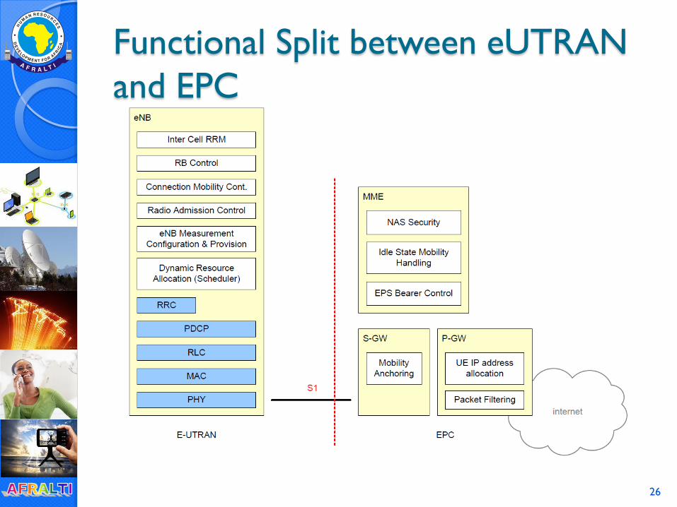
Functional Split between eUTRAN
and EPC
26
Network Evolution
RNC functions migrated to eNB and
MME
eNB Control Plane aggregation => MME
eNB User Plane aggregation => SGW
User Plane ciphering => eNB
NAS Signaling ciphering => MME
27