hr and hrm - raster zeulenroda - startseite zeulenroda … · 2012-11-06 · stamping and forming...
TRANSCRIPT

Machine and plant manufacture for stamping and forming technology
HR and HRM
STAMPING AND FORMING AUTOMATIC PRESSES
250 – 25,000 kN

Precision and flexibility –Proven by practice and innovative
Presses with follow-on composite tools are version for large series production. The stamping and forming automatic presses of the HR series from Raster-Zeulenroda are specialized in this field.The parts are kept together in sheet metal strips until finally detached in the follow-on composite and moved through the various tool stations in the strips.
Another alternative is forming techno-logies at several stages with transfer of parts. The stamping and forming automatic presses of the HR series are remarkable for the precision of all movements and long-term accuracy. This ensures that the quality of the products is on the same high level throughout a large series.
QUALITY AND PRECISION
HRM 250 HR 400 with 3-D transfer and integrated scrap transport system
2
> Press frames in monobloc design as welded steel construction connected to form a structure of high resistance to bending and torsional forces, stress relieved and FEM calculated, little ta-ble sag, exact parallelism between table and ram and high precision of the angular run of the ram along the full stroke length
> Multi-part welded steel construction> Optional: heat-treated multi-part spe-
cial casting design connected to form a particularly flexurally rigid frame by use of hydraulically prestressed steel anchors
> Coupling and braking system with extremely short braking angle
> Bearings located directly at force transmission points
> Special connecting rod mounting points on the outside of the ram for absorbing any eccentric loads occur-ring, connecting rod supported in half shells (standard), ball spindle with hy-draulic clamping (optional)
> Ram of welded steel construction (standard), of heat-treated special casting (optional), application-ori-ented with sliding or roller guides, efficient guide ratio
> Pneumatic ram and overhead tool weight balancing, counteracts the mass acceleration occurring during cutting processes especially during tooling-up
> With automatic ram adjustment> With automatic stroke adjustment> Press control by Beckhoff or Siemens> Drive design adapted to the applica-
tion of the machine > Adaptation of the machine’s working
space to customized tools> Optionally with separate creep speed
drive> Optionally as link version
Accessories/optional equipment> Strip line equipment> Coilers, recoilers> Roll feed> Transfer equipment> Toll carrier arms> Tool change plates> Roll block lifters> Hydraulic sliding clamps> Ram blockage> Oil collection pan
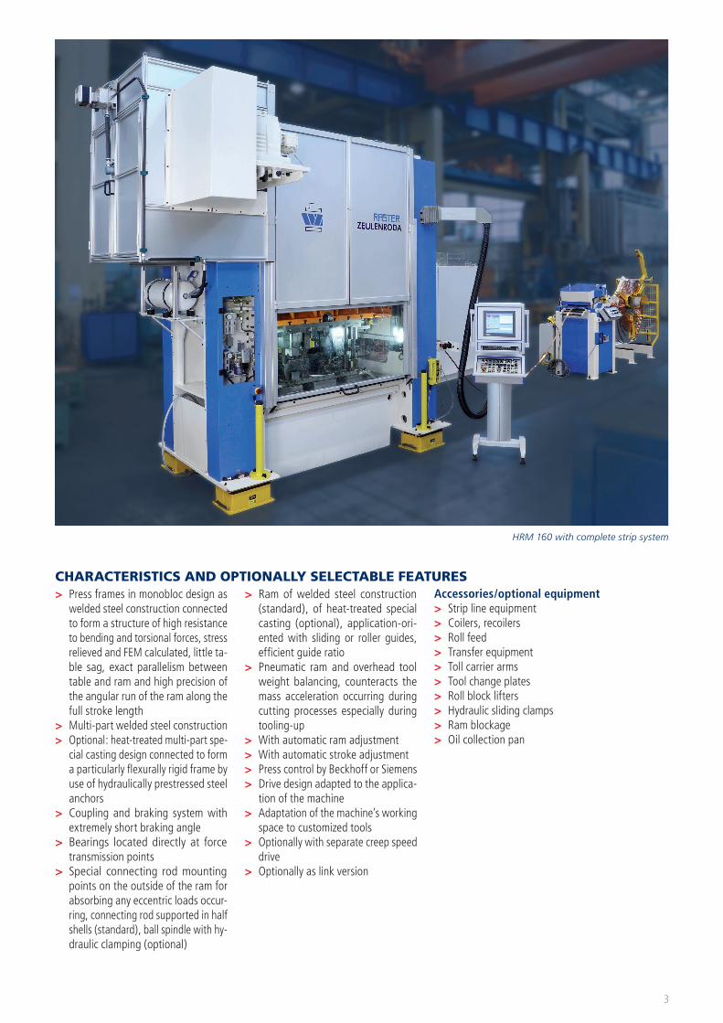
CHARACTERISTICS AND OPTIONALLY SELECTABLE FEATURES
3
HRM 160 with complete strip system
Press frame Monobloc Welded steel construction of high resist-ance to bending and torsional forces, stress relieved and FEM calculated.
> Nesting of welded walls ensures that force is not only transmitted through welds
> Little table sag> High parallelism between table and
ram > High accuracy of angular run across
the ram stroke > Table sizes up to 2,500 mm, pressing
forces up to 5,000 kN
Optional:Tie rod design / steel or special casting versions,torsionally resistant 4-part special-cast-ing press frame.The robust, 3-part cast frame absorbs the fine vibrations produced by cutting and/or punching. High and consistent work quality is guaranteed by the stabil-ity and rigidity of the table, ram and press frame. Hydraulically prestressed steel
anchors connect the frame components, effectively compensate any press forces occurring and prevent expansion of the press frame. This results in long tool service life at a consistently high part quality.
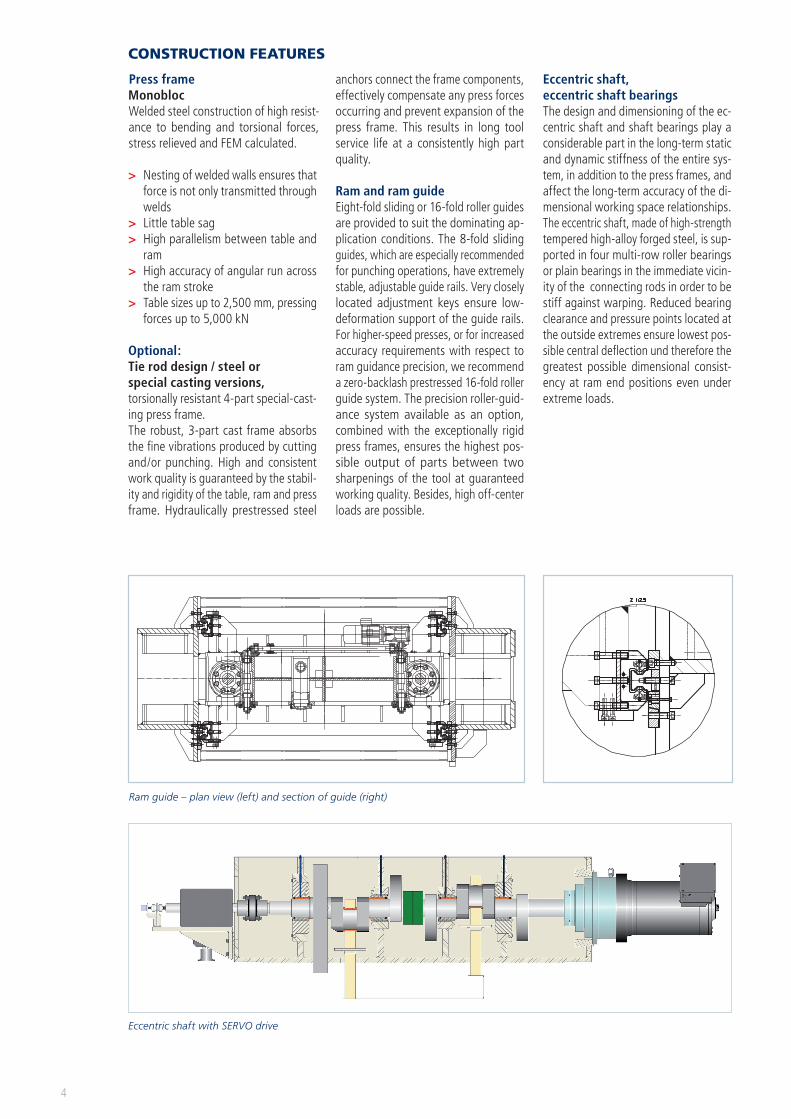
Ram and ram guideEight-fold sliding or 16-fold roller guides are provided to suit the dominating ap-plication conditions. The 8-fold sliding guides, which are especially recommended for punching operations, have extremely stable, adjustable guide rails. Very closely located adjustment keys ensure low-deformation support of the guide rails. For higher-speed presses, or for increased accuracy requirements with respect to ram guidance precision, we recommend a zero-backlash prestressed 16-fold roller guide system. The precision roller-guid-ance system available as an option, combined with the exceptionally rigid press frames, ensures the highest pos-sible output of parts between two sharpenings of the tool at guaranteed working quality. Besides, high off-center loads are possible.
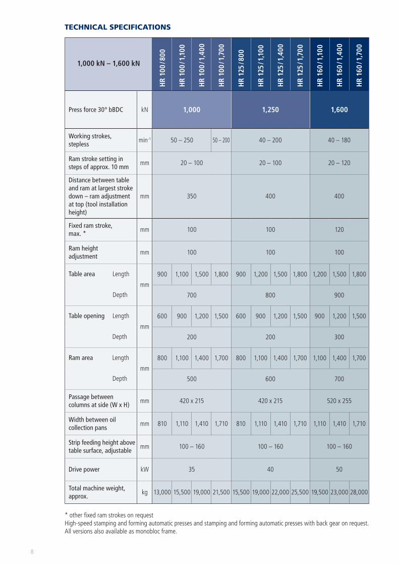
Eccentric shaft, eccentric shaft bearingsThe design and dimensioning of the ec-centric shaft and shaft bearings play a considerable part in the long-term static and dynamic stiffness of the entire sys-tem, in addition to the press frames, and affect the long-term accuracy of the di-mensional working space relationships.The eccentric shaft, made of high-strength tempered high-alloy forged steel, is sup-ported in four multi-row roller bearings or plain bearings in the immediate vicin-ity of the connecting rods in order to be stiff against warping. Reduced bearing clearance and pressure points located at the outside extremes ensure lowest pos-sible central deflection und therefore the greatest possible dimensional consist-ency at ram end positions even under extreme loads.
4
CONSTRUCTION FEATURES
Eccentric shaft with SERVO drive
Ram guide – plan view (left) and section of guide (right)

Connecting rod – ram force transmissionHighly wear-resistant and optimally di-mensioned force transmission joints lo-cated at the outside extremes of the ram are extremely important for the long-term accuracy of working space geometry under load. The tried-and-test-ed compression joint (of pressure shell design) consisting of the hardened and precision-ground cylinder contact face on the connecting rod and the counter-bearing in the height-adjustable spindle made of high-quality bearing metal, en-sures safe, low-wear transmission of the very highest forming and cutting forces.
Alternative:Supporting the connecting rod (pres-sure points) in a ball spindle design with hydraulic clamping (zero-backlash and low-wearing).
Hydraulic overload protectionIt reliably protects the machine and tools from overloading.A prestressed high-pressure hydraulic cushion is placed in the direct force flux in the ram underneath each connecting rod. If the preset press force is exceeded, the machine is shut down by the automatic high-speed shut-down system. Jamming of the ram is prevented by synchronizing both hydraulic cushions.Overload travel 20 mmResponse time < 10 ms
Ram adjustmentThe ram height is adjusted synchronously by motor within an accuracy of 0.01 mm via two threaded spindles. The height can be set in the tool data as part of the press control. Position clamping is hydraulic and fully automatic.
Working capacity
Ram weight compensationThe weights of the ram and the overhead tool are compensated sufficiently. The required air pressure is set manually at a controller or in the user surface (tool data). This facilitates the setting up pro-cess and improves the tool service life. The ram weight compensation is designed as bellows and in direct connection with the reservoir. There is no restriction, e.g., due to temperature, large strokes or high stroke frequencies which, ensures a large open cross section between the bellows and the reservoir.In addition, there is also no restriction of the degrees of freedom.
Stroke adjustmentStroke adjustment is fully automatic. The new type of pneumatically powered and mechanically synchronized stroke adjust-ment avoids jamming of the ram because all 4 stroke discs are moving synchro-nously. The sensitive adjustment enables variable latched positions:Standard = 10 strokes,up to 40 strokes are possible,adjustment time: max. 2 minThe system is locked mechanically. The ad-justment process is monitored electrically.
Stroke adjustment with SERVO drive:The presses with SERVO drive support free programming of ram strokes (pen-dulum mode) under stroke parameters. Fixed stroke can be selected for simple applications.
5
Ram – integrated adjustment
Connecting rod bearing – half shell
Ram weight compensation
Connecting rod bearing – in a ball spindle design
Wor
king
cap
acity
in k
Nm
Strokes per minute
Direct drive
Intermediate gear

6
DRIVE AND CONTROL
DESCH-SERVOX®-planetary gear
Possible drive concepts> Conventional with intermediate gear> Complete drive> Link drive> SERVO drive (as direct drive or with intermediate planetary gear)
Inverter driveThis drive can be varied steplessly by re-mote adjustment of the speed from the operator console.The working capacity is always designed according to the customer’s part range.
Power trainMotor – belt pulley – belt – complete drive – crankshaft – connecting rod – ram
Complete driveThe complete drive of the press replac-es the complete spur-type intermediate gear or one or two gear stages at the stamping and forming automatic press, for which the energy required by the machine is obtained from the flywheel running at high speed.
Link driveThe link drive substantially reduces the impact speed of the ram, including that of the overhead tool, in comparison with conventional drive solutions. The addi-tional articulation in the drive system has a positive effect on the ram move-ment. In addition, the tool service life is increased considerably.
Benefits:> Longer tool life > Fast upward travel> Increased part output
The link system ensures that forces gen-erated by the punching process, which act on the eccentric shaft, are not trans-ferred into the drive system.
SERVO drive with/without inter-mediate planetary gearThis drive is implemented with high-torque motors which – depending on the application – are connected to the eccentric shaft or by a low-backlash planetary gear. The SERVO motor is the power source of the machine. The intel-ligent control supports programming different speed profiles, which makes the machine highly flexible and suitable for different applications. The machine output can also be increased with this configuration. The speed of the stepless- control torque motor is adjustable at the operator panel.
Features of the SERVO drive:> High torque with compact design and
small construction volume > Optimized mechatronic solution> Highest rigidity> High speeds possible> Improves productivity and product
quality > High dynamic action (fast accelera-
tion)> Excellent true running> The suitable motor for low-energy
solutions
Benefits:> Gentle cutting> Difficult contours are produced very
exactly> Long tool life> Low noise emission> Fast upward travel > High output of parts > Reduced auxiliary process times
Energy management:> Based on capacitor modules; or elec-
tro-mechanical storage motor> The generator energy is stored in
the intermediate circuit in such a way that the total connected load of the stamping and forming automatic press is similar to or lower than that of mechanical machines
The press controlOptimum for the press operator:> Complete information on the press
and the job at any time> Automatic operator prompts
Optimal for the machine setter:> Simple, function-oriented program-
ming of tool data, notepad and photo album for every tool
> Reference function to prior tool settings or other tools
Optimum for maintenance:> Extensive press diagnostic function
with link to on-line help (Beckhoff)> On-line help with photos of all sen-
sors for quick localization to speed up problem resolution (Beckhoff)
> Maintenance interval with reminder function (for machine, peripherals and tool)
Optimum for production planning:> Automatic recording of job-specific
data> Automatic update of the job history Optional:> Web server for remote monitoring of
the machine via the intranet
Comprehensive remote service:> User support> Program updates
Control from Beckhoff orSiemens:> TFT color screen control on basis of
Beckhoff PC control with soft PLC> PC-integrated operating hours coun-
ter; Raster-Zeulenroda visualization under Windows
> PLC with Simatic S7-300 and 15’’ touch panel with color display; pro-gramming with structured text (SCL + SCL-Petri nets); visualization based on WinCC flexible
> Simotion control for machines with SERVO direct drive;
Raster-Zeulenroda- visualization un-der Windows

7
Visualization system
Comprehensive comfortable Raster-
Zeulenroda visualization based on Windows XP Pro
Simple visualization based on Siemens
WinCC flexible
Visualization based on SiemensWinCC
Cont
rol,
field
bus
BeckhoffTwinCAT,EtherCAT
SIMATIC S7,Profibus
SIMOTIONProfinet
Overview of control versions
Photo credits: Beckhoff Automation GmbH
HR 800 with transversal shaft drive
1,000 kN – 1,600 kN
HR
100
/ 800
HR
100
/ 1,1
00
HR
100
/ 1,4
00
HR
100
/ 1,7
00
HR
125
/ 800
HR
125
/ 1,1
00
HR
125
/ 1,4
00
HR
125
/ 1,7
00
HR
160
/ 1,1
00
HR
160
/ 1,4
00
HR
160
/ 1,7
00
Press force 30° bBDC kN 1,000 1,250 1,600
Working strokes, stepless
min-1 50 – 250 50 – 200 40 – 200 40 – 180
Ram stroke setting in steps of approx. 10 mm
mm 20 – 100 20 – 100 20 – 120
Distance between table and ram at largest stroke down – ram adjustment at top (tool installation height)
mm 350 400 400
Fixed ram stroke, max. *
mm 100 100 120
Ram height adjustment
mm 100 100 100
Table area Length
Depth
mm
900 1,100 1,500 1,800 900 1,200 1,500 1,800 1,200 1,500 1,800
700 800 900
Table opening Length
Depth
mm
600 900 1,200 1,500 600 900 1,200 1,500 900 1,200 1,500
200 200 300
Ram area Length
Depth
mm
800 1,100 1,400 1,700 800 1,100 1,400 1,700 1,100 1,400 1,700
500 600 700
Passage between columns at side (W x H)
mm 420 x 215 420 x 215 520 x 255
Width between oil collection pans
mm 810 1,110 1,410 1,710 810 1,110 1,410 1,710 1,110 1,410 1,710
Strip feeding height above table surface, adjustable
mm 100 – 160 100 – 160 100 – 160
Drive power kW 35 40 50
Total machine weight, approx.
kg 13,000 15,500 19,000 21,500 15,500 19,000 22,000 25,500 19,500 23,000 28,000
* other fixed ram strokes on requestHigh-speed stamping and forming automatic presses and stamping and forming automatic presses with back gear on request.All versions also available as monobloc frame.
TECHNICAL SPECIFICATIONS
8

2,000 kN – 3,150 kN
HR
200
/ 1,1
00
HR
200
/ 1,4
00
HR
200
/ 1,7
00
HR
200
/ 2,0
00
HR
250
/ 1,3
00
HR
250
/ 1,6
00
HR
250
/ 1,9
00
HR
250
/ 2,2
00
HR
250
/ 2,5
00
HR
315
/ 1,6
00
HR
315
/ 1,9
00
HR
315
/ 2,2
00
HR
315
/ 2,5
00
Press force 30° bBDC kN 2,000 2,500 3,150
Working strokes, stepless
min-1 40 – 200 40 –180 40 – 200 40 – 180 30 – 120
Ram stroke setting in steps of approx. 10 mm
mm 20 – 120 20 – 120 30 – 200
Distance between table and ram at largest stroke down – ram adjustment at top (tool installation height)
mm 465 465 500
Fixed ram stroke, max. *
mm 150 150 200
Ram height adjustment
mm 100 150 150
Table area Length
Depth
mm
1,200 1,500 1,800 2,100 1,400 1,700 2,000 2,300 2,600 1,700 2,000 2,300 2,600
1000 1.100 1.200
Table opening Length
Depth
mm
900 1,200 1,500 1,800 1,100 1,400 1,700 2,000 2,300 1,400 1,700 2,000 2,300
300 300 400
Ram area Length
Depth
mm
1,100 1,400 1,700 2,000 1,300 1,600 1,900 2,200 2,500 1,600 1,900 2,200 2,500
800 900 1,000
Passage between columns at side (W x H)
mm 520 x 255 820 x 300 820 x 300
Width between oil collection pans
mm 1,110 1,410 1,710 2,010 1,310 1,610 1,910 2,210 2,510 1,610 1,910 2,210 2,510
Strip feeding height above table surface, adjustable
mm 120 – 200 120 – 200 120 – 200
Drive power kW 60 70 80
Total machine weight, approx.
kg 28,000 31,500 35,000 37,000 38,500 42,500 47,000 51,000 57,000 47,000 51,000 57,000 62,000
* other fixed ram strokes on requestHigh-speed stamping and forming automatic presses and stamping and forming automatic presses with back gear on request.All versions also available as monobloc frame.
9

4,000 kN – 5,000 kN
HR
400
/ 1,6
00
HR
400
/ 1,9
00
HR
400
/ 2,2
00
HR
400
/ 2,5
00
HR
400
/ 2,8
00
HR
500
/ 1,6
00
HR
500
/ 1,9
00
HR
500
/ 2,2
00
HR
500
/ 2,5
00
HR
500
/ 2,8
00
HR
500
/ 3,6
00
Press force 30° bBDC kN 4,000 5,000
Working strokes, stepless
min-1 20 – 100 20 – 80
Ram stroke setting in steps of approx. 10 mm
mm 40 – 200 40 – 200 80 – 300
Distance between table and ram at largest stroke down – ram adjustment at top (tool installation height)
mm 600 600 700
Fixed ram stroke, max. *
mmIn these versions are not available.
In these versions are not available.
Ram height adjustment
mm 200 200
Table area Length
Depth
mm
1,700 2,000 2,300 2,600 2,900 1,700 2,000 2,300 2,600 2,900 3,600
1,200 1,300 1,400
Table opening Length
Depth
mm
1,400 1,700 2,000 2,300 2,600 1,400 1,700 2,000 2,300 2,600 3,300
400 400
Ram area Length
Depth
mm
1,600 1,900 2,200 2,500 2,800 1,600 1,900 2,200 2,500 2,800 3,600
1,000 1,100 1,200
Passage between columns at side (W x H)
mm 900 x 500 900 x 5001,000 x
500
Width between oil collection pans
mm 1,610 1,910 2,210 2,510 2,810 1,610 1,910 2,210 2,510 2,810 3,800
Strip feeding height above table surface, adjustable
mm 150 – 250 180 – 300
Drive power kW 100 110 135
Total machine weight, approx.
kg 60,500 65,000 70,500 77,500 85,00 64,000 68,000 74,000 80,000 87,000 106,500
High-speed stamping and forming automatic presses and stamping and forming automatic presses with back gear on request.Monobloc frame available up to press force of 500 tons and 2,500 table.
10
TECHNICAL SPECIFICATIONS
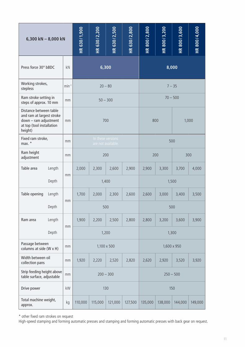
6,300 kN – 8,000 kN
HR
630
/ 1,9
00
HR
630
/ 2,2
00
HR
630
/ 2,5
00
HR
630
/ 2,8
00
HR
800
/ 2,8
00
HR
800
/ 3,2
00
HR
800
/ 3,6
00
HR
800
/ 4,0
00
Press force 30° bBDC kN 6,300 8,000
Working strokes, stepless
min-1 20 – 80 7 – 35
Ram stroke setting in steps of approx. 10 mm
mm 50 – 30070 – 500
Distance between table and ram at largest stroke down – ram adjustment at top (tool installation height)
mm 700 800 1,000
Fixed ram stroke, max. *
mmIn these versions are not available.
500
Ram height adjustment
mm 200 200 300
Table area Length
Depth
mm
2,000 2,300 2,600 2,900 2,900 3,300 3,700 4,000
1,400 1,500
Table opening Length
Depth
mm
1,700 2,000 2,300 2,600 2,600 3,000 3,400 3,500
500 500
Ram area Length
Depth
mm
1,900 2,200 2,500 2,800 2,800 3,200 3,600 3,900
1,200 1,300
Passage between columns at side (W x H)
mm 1,100 x 500 1,600 x 950
Width between oil collection pans
mm 1,920 2,220 2,520 2,820 2,620 2,920 3,520 3,920
Strip feeding height above table surface, adjustable
mm 200 – 300 250 – 500
Drive power kW 130 150
Total machine weight, approx.
kg 110,000 115,000 121,000 127,500 135,000 138,000 144,000 149,000
* other fixed ram strokes on requestHigh-speed stamping and forming automatic presses and stamping and forming automatic presses with back gear on request.
11

12
TOOLS
Table surface
Ram surface
Coil feeding

Model A B C D E F H J K L M N O
HR 100 / 800 900
700 420
600
200
1,080 800
500
1,040
260 150 –
8
HR 100 / 1,000 1,200 900 1,380 1,100 1,340 8
HR 100 / 1,400 1,500 1,200 1,680 1,400 1,640 12
HR 100 / 1,700 1,800 1,500 1,980 1,700 1,940 16
HR 125 / 800 900
800 420
600
200
1,080 800
600
1,040
260 180 –
8
HR 125 / 1,100 1,200 900 1,380 1,100 1,340 8
HR 125 / 1,400 1,500 1,200 1,680 1,400 1,640 12
HR 125 / 1,700 1,800 1,500 1,980 1,700 1,940 16
HR 160 / 1,100 1,200
900 520
900
300
1,380 1,100
700
1,340
350 180 –
8
HR 160 / 1,400 1,500 1,200 1,680 1,400 1,640 12
HR 160 / 1,700 1,800 1,500 1,980 1,700 1,940 16
HR 200 / 1,100 1,200
1,000 520
900
300
1,380 1,100
800
1,360
350 230 –
8
HR 200 / 1,400 1,500 1,200 1,680 1,400 1,660 12
HR 200 / 1,700 1,800 1,500 1,980 1,700 1,960 16
HR 200 / 2,000 2,100 1,800 2,280 2,000 2,260 20
HR 250 / 1,300 1,400
1,100 820
1,100
300
1,640 1,300
900
1,560
560 230 –
12
HR 250 / 1,600 1,700 1,400 1,940 1,600 1,860 16
HR 250 / 1,900 2,000 1,700 2,240 1,900 2,160 20
HR 250 / 2,200 2,300 2,000 2,540 2,200 2,460 24
HR 250 / 2,500 2,600 2,300 2,840 2,500 2,760 28
HR 315 / 1,600 1,700
1,200 820
1,400
400
1,940 1,600
1,000
1,860
560 300 250
16
HR 315 / 1,900 2,000 1,700 2,240 1,900 2,160 20
HR 315 / 2,200 2,300 2,000 2,540 2,200 2,460 24
HR 315 / 2,500 2,600 2,300 2,840 2,500 2,760 28
HR 400 / 1,600 1,700
1,200 900
1,400
400
1,940 1,600
1,000
1,860
620 300 250
16
HR 400 / 1,900 2,000 1,700 2,240 1,900 2,160 20
HR 400 / 2,200 2,300 2,000 2,540 2,200 2,460 20
HR 400 / 2,500 2,600 2,300 2,840 2,500 2,760 24
HR 400 / 2,800 2,900 2,600 3,140 2,800 3,060 24
HR 500 / 1,600 1,700
1,300 900
1,400
400
1,940 1,600
1,100
1,860
620 300 250
16
HR 500 / 1,900 2,000 1,700 2,240 1,900 2,160 20
HR 500 / 2,200 2,300 2,000 2,540 2,200 2,460 20
HR 500 / 2,500 2,600 2,300 2,840 2,500 2,760 24
HR 500 / 2,800 2,900 2,600 3,140 2,800 3,060 24
HR 500 / 3,600 3,600 1,400 1,000 3,300 3,800 3,600 1,200 3,860 36
HR 630 / 1,900 2,000
1,400 1,100
1,700
500
2,400 1,900
1,200
2,260
760 400 300
20
HR 630 / 2,200 2,300 2,000 2,700 2,200 2,560 20
HR 630 / 2,500 2,600 2,300 3,000 2,500 2,860 24
HR 630 / 2,800 2,900 2,600 3,300 2,800 3,160 24
HR 800 / 2,800 2,900
1,600 1,300
2,600
500
3,140 2,800
1,400
3,160
1,240 620 400
20
HR 800 / 3,200 3,300 2,900 3,540 3,200 3,460 20
HR 800 / 3,600 3,700 3,300 3,940 3,600 3,860 24
HR 800 / 4,000 4,000 3,700 4,340 4,000 3,960 24
Other dimensions on request.
Tool installation dimensions 1,000 kN – 8,000 kN
13

PRINCIPAL DIMENSIONS
14
Front view
Side view
Hydraulic unit

Model A B B* C D E F G H L M
HRM 100 / 800 1,050 1,850 2,150 1,840
1,100 1,400 2,3403,100 3,800
125 215HRM 100 / 1,100 1,200 2,000 2,300 2,140HRM 100 / 1,400 1,450 2,150 2,450 2,440HRM 100 / 1,700 1,600 2,300 2,600 2,740 3,200 3,900HRM 125 / 800 1,050 1,850 2,150 1,840
1,100 1,400 2,5403,150 3,900
125 215HRM 125 / 1,100 1,200 2,000 2,300 2,140HRM 125 / 1,400 1,450 2,150 2,450 2,440HRM 125 / 1,700 1,600 2,300 2,600 2,740 3,250 3,950HRM 160 / 1,100 1,230 2,200 2,500 2,200
1,100 1,500 2,6003,300 4,000
125 255HRM 160 / 1,400 1,480 2,350 3,650 2,500HRM 160 / 1,700 1,630 2,500 2,800 2,800 3,400 4,100HRM 200 / 1,100 1,230 2,200 2,500 2,200
1,100 1,500 2,8003,350 4,100
125 255HRM 200 / 1,400 1,480 2,350 2,650 2,500HRM 200 / 1,700 1,530 2,500 2,800 2,800 3,450 4,150HRM 200 / 2,000 1,680 2,360 2,660 3,100 3,550 4,250HRM 250 / 1,300 1,450 2,250 2,550 2,230
1,200 1,700 3,000
3,600 4,600
150 300HRM 250 / 1,600 1,600 2,400 2,700 2,530HRM 250 / 1,900 1,750 2,550 2,850 2,830 3,700 4,700HRM 250 / 2,200 1,900 2,700 3,000 3,130 3,800 4,800HRM 250 / 2,500 2,050 2,850 3,150 3,430 3,900 4,900HRM 315 / 1,600 1,450 2,250 2,550 2,530
1,200 1,700 3,000
3,700 4,900
150 300HRM 315 / 1,900 1,600 2,400 2,700 2,830 3,800 4,900HRM 315 / 2,200 1,750 2,550 2,850 3,130 3,900 5,000HRM 315 / 2,500 1,900 2,700 3,000 3,430 4,100 5,100
Principal dimensions 1,000 kN – 3,150 kN
Principal dimensions with drive unit (planetary gear, flywheel, coupling, brake) 4,000 kN – 8,000 kN
Model A B B* C D E F G H I J
HRM 400 / 1,600 2,400 2,000 2,500 2,900
1,300 2,000 3,3004,600 5,550
150 500HRM 400 / 1,900 2,550 2,150 2,650 3,200HRM 400 / 2,200 2,700 2,300 2,800 3,500HRM 400 / 2,500 2,850 2,450 2,950 3,800 4,700 5,650HRM 400 / 2,800 3,000 2,600 3,100 4,100 4,800 5,700HRM 500 / 1,600 2,400 2,000 2,500 2,900
1,300 2,000 3,300
4,600 5,650 150
500
HRM 500 / 1,900 2,550 2,150 2,650 3,200HRM 500 / 2,200 2,700 2,300 2,800 3,500HRM 500 / 2,500 2,850 2,450 2,950 3,800 4,800 5,800
200HR 500 / 2,800 3,000 2,600 3,100 4,100 5,000 5,900HR 500 / 3,600 3,400 3,200 3,700 4,900 6,200 5,900HR 630 / 1,900 2,050 3,350 3,850 3,300
1,700 2,000 3,5005,900 6,600
200 500HR 630 / 2,200 2,200 3,500 4,000 3,600HR 630 / 2,500 2,350 3,650 4,150 3,900HR 630 / 2,800 2,500 3,800 4,300 4,200 6,000 6,700HR 800 / 2,800 3,210 – 3,210 5,000 2,200 3,400 4,000 8,400 9,000 300 800HR 800 / 3,200 3,410 – 3,410 5,400 2,400 3,400 4,000 8,400 9,000 300 800HR 800 / 3,600 3,610 – 3,510 5,900 2,400 3,400 4,200 8,800 9,400 300 1,000HR 800 / 4,000 3,810 – 3,810 6,300 2,400 3,400 4,200 8,800 9,400 300 1,000
B* with back gearOther dimensions on request.
B* with back gear
15

Köln 530 kmLeipzig 110 km
Hamburg 600 km
Hannover 460 km Berlin 300 km
Dresden 180 km
ZeulenrodaFrankfurt 380 km
Stuttgart 400 km
Nürnberg 180 km
München 340 km
Prag 300 km
Wien 650 km
Raster-ZeulenrodaWerkzeugmaschinen GmbH
Triebeser Straße 5D - 07937 Zeulenroda-TriebesTel.: + 49 (0) 3 66 28 / 42 - 0Fax: + 49 (0) 3 66 28 / 42 - 239Email: [email protected]
Machine and plant manufacture forstamping and forming technology
> TRANSFER FORMING AUTOMATIC PRESSES> STAMPING AND FORMING AUTOMATIC PRESSES> TOOL TESTING AND PRODUCTION PRESSES > HYDRAULIC OPEN-FRONT AND DOUBLE-SIDED PRESSES > SPECIAL-PURPOSE PRESSES AND SPECIAL CONSTRUCTIONS > SERVICE AND GENERAL MAINTENANCE> JOB ORDER PRODUCTION
Dat
e: 1
0/20
12
w
ww
.mar
ofke
-wer
bung
.de
P
hoto
s: fo
tolia