hpn gearhead series gearhead series hpn ... - … gearheads hpn series high-performance gearhead for...
TRANSCRIPT
1 Gearheads
HPN
Serie
sHi
gh-P
erfo
rman
ce G
earh
ead
for S
ervo
mot
ors
HPN
Serie
sHi
gh-P
erfo
rman
ce G
earh
ead
for S
ervo
mot
ors
HPN Gearhead Series
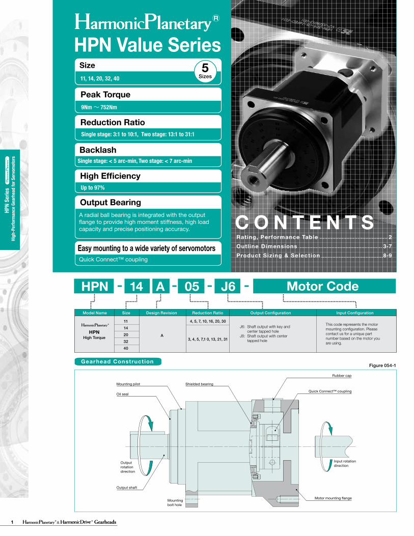
HPN Value Series
Figure 054-1
Size11, 14, 20, 32, 40 Sizes
5
9Nm~ 752Nm
Single stage: 3:1 to 10:1, Two stage: 13:1 to 31:1
Mounting pilot Shielded bearing
Output rotation direction
Output shaft
Mounting bolt hole
Motor mounting flange
Input rotation direction
Rubber cap
Quick Connect™ couplingOil seal
2
3-7
8-9
Rating, Performance TableOutl ine DimensionsProduct Sizing & Selection
C O N T E N T SQuick Connect™ coupling
Gearhead Construction
C O N T E N T S
HPN Series .....13-20
HPGP Series .....21-30
HPG Series .....33-43
HPG Series - Right Angle .....45-54
Gearhead Series
Technical Information.......98-120
Major Applications of Our Products.....121
CSG-GH Series .....55-77
CSF-GH Series .....55-77
HPF Series - Hollow Shaft .....79-84
HPG Series - Input Shaft .....85-95
Unit Type
HPNHigh Torque A
1114203240
4, 5, 7, 10, 16, 20, 30
3, 4, 5, 7,1 0, 13, 21, 31
HPN 14 A 05 J6- ---
J6: Shaft output with key and center tapped hole
J8: Shaft output with center tapped hole
Model Name Size Design Revision Reduction Ratio Output Configuration Input Configuration
This code represents the motor mounting configuration. Please contact us for a unique part number based on the motor you are using.
Motor Code
Easy mounting to a wide variety of servomotors
A radial ball bearing is integrated with the output flange to provide high moment stiffness, high load capacity and precise positioning accuracy.
Peak Torque
Reduction Ratio
Up to 97%
High Efficiency
Output Bearing
Single stage: < 5 arc-min, Two stage: < 7 arc-minBacklash
2Gearheads
HPN
Serie
sHi
gh-P
erfo
rman
ce G
earh
ead
for S
ervo
mot
ors
HPN
Serie
sHi
gh-P
erfo
rman
ce G
earh
ead
for S
ervo
mot
ors
HPN Gearhead Series
Performance
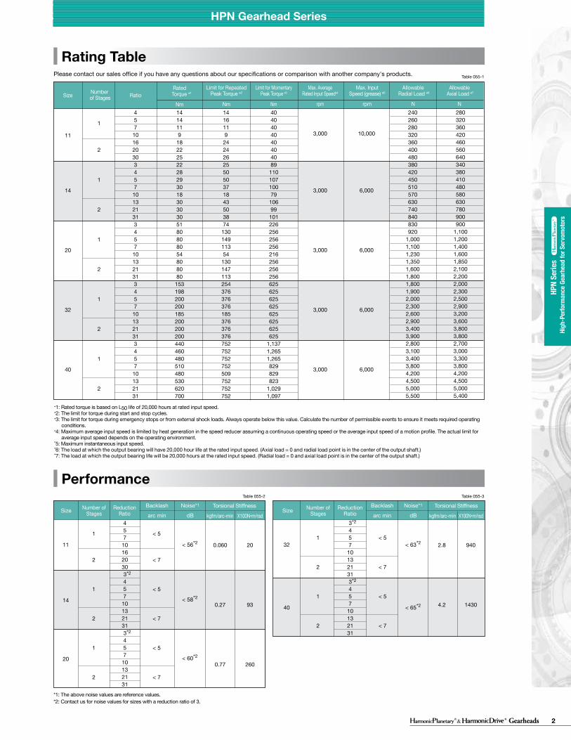
Rating TablePlease contact our sales office if you have any questions about our specifications or comparison with another company's products.
457
10162030
3*2
457
10132131
3*2
457
10132131
< 5
< 7
< 5
< 7
< 5
< 7
< 56*2
< 58*2
< 60*2
1
2
1
2
1
2
11
14
20
Number of StagesSize Reduction
RatioBacklash
arc min
Noise*1
dB 3*2
457
10132131
3*2
457
10132131
< 5
< 7
< 5
< 7
< 63*2
< 65*2
1
2
1
2
32
40
Number of StagesSize Reduction
RatioBacklash
arc min
Noise*1
dB
*1: Rated torque is based on L50 life of 20,000 hours at rated input speed.*2: The limit for torque during start and stop cycles.*3: The limit for torque during emergency stops or from external shock loads. Always operate below this value. Calculate the number of permissible events to ensure it meets required operating conditions. *4: Maximum average input speed is limited by heat generation in the speed reducer assuming a continuous operating speed or the average input speed of a motion profile. The actual limit for average input speed depends on the operating environment.*5: Maximum instantaneous input speed.*6: The load at which the output bearing will have 20,000 hour life at the rated input speed. (Axial load = 0 and radial load point is in the center of the output shaft.)*7: The load at which the output bearing life will be 20,000 hours at the rated input speed. (Radial load = 0 and axial load point is in the center of the output shaft.)
*1: The above noise values are reference values.*2: Contact us for noise values for sizes with a reduction ratio of 3.
Table 055-1
Table 055-2 Table 055-3
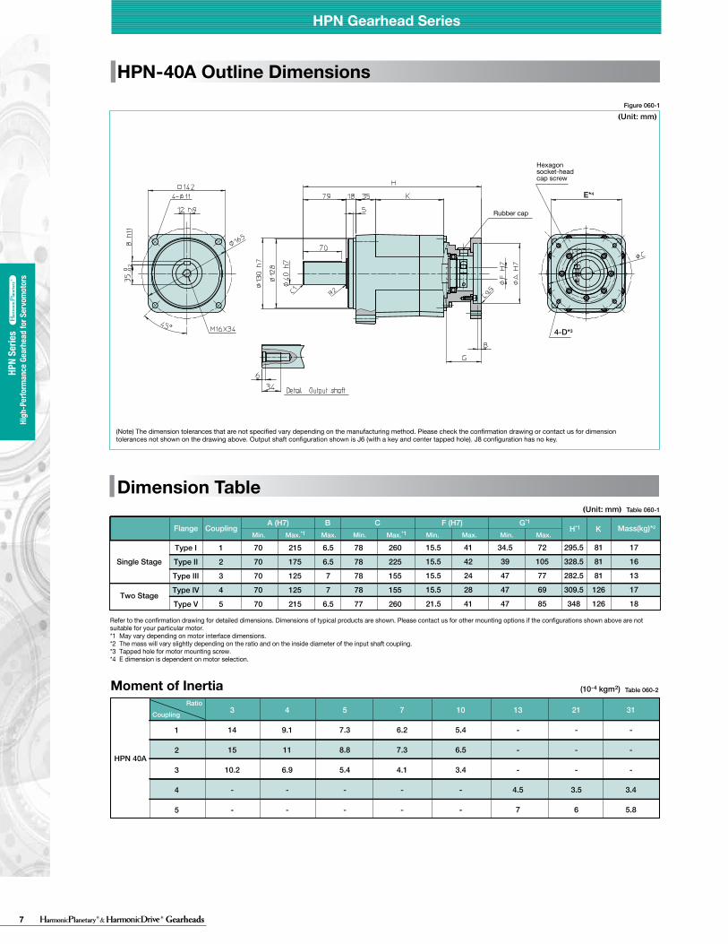
Figure 060-1
Table 060-1
HPN-40A Outline Dimensions
Dimension Table
Rubber cap
Hexagon socket-head cap screw
HPN Gearhead Series HPN Gearhead Series
(Note) The dimension tolerances that are not specified vary depending on the manufacturing method. Please check the confirmation drawing or contact us for dimension tolerances not shown on the drawing above. Output shaft configuration shown is J6 (with a key and center tapped hole). J8 configuration has no key.
E*4
4-D*3
457
101620303457
101321313457
101321313457
101321313457
10132131
14 14 11 9
18 22 25 22 28 29 30 18 30 30 30 51 80 80 80 54 80 80 80
153 198 200 200 185 200 200 200 440 460 480 510 480 530 620 700
14 16 11 9
24 24 26 25 50 50 37 18 43 50 38 74
130 149 113 54
130 147 113 254 376 376 376 185 376 376 376 752 752 752 752 509 752 752 752
40 40 40 40 40 40 40 89
110 107 100 79
106 99
101 226 256 256 256 216 256 256 256 625 625 625 625 625 625 625 625
1,137 1,265 1,265 829 829 823
1,029 1,097
240260280320360400480380420450510570630740840830920
1,0001,1001,2301,3501,6001,8001,8001,9002,0002,3002,6002,9003,4003,9002,8003,1003,4003,8004,2004,5005,0005,500
280320360420460560640340380410480580630780900900
1,1001,2001,4001,6001,8502,1002,2002,0002,3002,5002,9003,2003,6003,8003,8002,7003,0003,3003,8004,2004,5005,0005,400
3,000
3,000
3,000
3,000
3,000
10,000
6,000
6,000
6,000
6,000
1
2
1
2
1
2
1
2
1
2
11
14
20
32
40
Number of StagesSize Ratio
Rated Torque ※1
Nm
Limit for Repeated Peak Torque ※2
Nm
Limit for Momentary Peak Torque ※3
Nm
Max. AverageRated Input Speed※4
rpm
Max. Input Speed (grease) ※5
rpm
Allowable Radial Load ※6
N
Allowable Axial Load ※7
N
0.060
0.27
0.77
20
93
260
Torsional Stiffness
kgfm/arc-min X100N•m/rad
2.8
4.2
940
1430
Torsional Stiffness
kgfm/arc-min X100N•m/rad
Moment of Inertia
Refer to the confirmation drawing for detailed dimensions. Dimensions of typical products are shown. Please contact us for other mounting options if the configurations shown above are not suitable for your particular motor. *1 May vary depending on motor interface dimensions. *2 The mass will vary slightly depending on the ratio and on the inside diameter of the input shaft coupling.*3 Tapped hole for motor mounting screw.*4 E dimension is dependent on motor selection.
Table 060-2
3
14
15
10.2
-
-
4
9.1
11
6.9
-
-
5
7.3
8.8
5.4
-
-
7
6.2
7.3
4.1
-
-
10
5.4
6.5
3.4
-
-
13
-
-
-
4.5
7
21
-
-
-
3.5
6
31
-
-
-
3.4
5.8
1
2
3
4
5
HPN 40A
(Unit: mm)
(Unit: mm)
(10-4 kgm2)
CouplingRatio
BA (H7)Flange Coupling
CMin. Max.*1 Max. Min. Max.*1
Single Stage
Two Stage
G*1
15.5
15.5
15.5
15.5
21.5
41
42
24
28
41
34.5
39
47
47
47
72
105
77
69
85
295.5
328.5
282.5
309.5
348
81
81
81
126
126
17
16
13
17
18
F (H7)H*1
Min. Max. Min. Max.K Mass(kg)*2
Type I
Type II
Type III
Type IV
Type V
1
2
3
4
5
70
70
70
70
70
215
175
125
125
215
6.5
6.5
7
7
6.5
78
78
78
78
77
260
225
155
155
260
HPN
serie
s
HPN
serie
s
3 Gearheads
HPN
Serie
sHi
gh-P
erfo
rman
ce G
earh
ead
for S
ervo
mot
ors
HPN
Serie
sHi
gh-P
erfo
rman
ce G
earh
ead
for S
ervo
mot
ors
HPN Gearhead Series
(Unit: mm) (Unit: mm)
(Unit: mm)(Unit: mm)
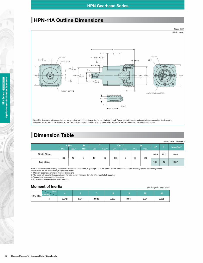
Moment of Inertia (10-4 kgm2) (10-4 kgm2)Table 056-2
4
0.042
5
0.04
7
0.038
10
0.037
16
0.04
20
0.04
30
0.0381HPN 11A
Refer to the confirmation drawing for detailed dimensions. Dimensions of typical products are shown. Please contact us for other mounting options if the configurations shown above are not suitable for your particular motor. *1 May vary depending on motor interface dimensions. *2 The mass will vary slightly depending on the ratio and on the inside diameter of the input shaft coupling.*3 Tapped hole for motor mounting screw.*4 E dimension is dependent on motor selection.
Moment of Inertia
Refer to the confirmation drawing for detailed dimensions. Dimensions of typical products are shown. Please contact us for other mounting options if the configurations shown above are not suitable for your particular motor. *1 May vary depending on motor interface dimensions. *2 The mass will vary slightly depending on the ratio and on the inside diameter of the input shaft coupling.*3 Tapped hole for motor mounting screw.*4 E dimension is dependent on motor selection.
Table 057-2
3
0.24
0.124
4
0.21
0.096
5
0.2
0.083
7
0.19
0.072
10
0.19
0.066
13
0.2
0.049
21
0.2
0.043
31
-
0.041
1
2
HPN 14A
HPN-11A Outline DimensionsFigure 056-1 Figure 057-1
Dimension Table
(Note) The dimension tolerances that are not specified vary depending on the manufacturing method. Please check the confirmation drawing or contact us for dimension tolerances not shown on the drawing above. Output shaft configuration shown is J6 (with a key and center tapped hole). J8 configuration has no key.
(Note) The dimension tolerances that are not specified vary depending on the manufacturing method. Please check the confirmation drawing or contact us for dimension tolerances not shown on the drawing above. Output shaft configuration shown is J6 (with a key and center tapped hole). J8 configuration has no key.
HPN-14A Outline Dimensions
Dimension TableTable 056-1 Table 057-1
BA (H7) C F (H7)Min. Max.*4 Max. Min. Max.*4 Min. Max.
30 42 3 35 49 4.8 9 15 26 86.5 27.5 0.44
106 47 0.57
Single Stage
Two Stage
B
30Type I
Type II
1
2
39 5 35 49
A (H7)
CouplingRatio
Flange CouplingC
Min. Max.*1 Max. Min. Max.*1
Single Stage
Single Stage50 59 5 56 74
Two Stage
Two Stage
G
4.8 8 17 25107
132
112
137
36
61
36
61
0.95
1.3
1.2
1.6
F (H7)H*1
Min. Max. Min. Max.
4.8 14 24 31
K
Y
E
DETAIL Y
*4
4-D*3
CouplingRatio
GH*1 K Mass(kg)*2
Min. Max.Mass(kg)*2
HPN Gearhead Series HPN Gearhead Series
HPN
serie
s
HPN
serie
s
Y
G
B
18
2.5
9
6.5 19.5
K
0 F H7 0.025
H
0.0180
-13 h7
35 h7 - A H7 E
C
M3x0.5 COUPLING SCREW
DETAIL Y 3
4.5
12
3.44X
42
50
0.0300
- 5 h9
0.0300
- 5 h9
10-00.1
M4X0.7 - 6H 12
*4
4-D*3

4Gearheads
HPN
Serie
sHi
gh-P
erfo
rman
ce G
earh
ead
for S
ervo
mot
ors
HPN
Serie
sHi
gh-P
erfo
rman
ce G
earh
ead
for S
ervo
mot
ors
HPN Gearhead Series
(Unit: mm) (Unit: mm)
(Unit: mm)(Unit: mm)
Moment of Inertia (10-4 kgm2) (10-4 kgm2)Table 056-2
4
0.042
5
0.04
7
0.038
10
0.037
16
0.04
20
0.04
30
0.0381HPN 11A
Refer to the confirmation drawing for detailed dimensions. Dimensions of typical products are shown. Please contact us for other mounting options if the configurations shown above are not suitable for your particular motor. *1 May vary depending on motor interface dimensions. *2 The mass will vary slightly depending on the ratio and on the inside diameter of the input shaft coupling.*3 Tapped hole for motor mounting screw.*4 E dimension is dependent on motor selection.
Moment of Inertia
Refer to the confirmation drawing for detailed dimensions. Dimensions of typical products are shown. Please contact us for other mounting options if the configurations shown above are not suitable for your particular motor. *1 May vary depending on motor interface dimensions. *2 The mass will vary slightly depending on the ratio and on the inside diameter of the input shaft coupling.*3 Tapped hole for motor mounting screw.*4 E dimension is dependent on motor selection.
Table 057-2
3
0.24
0.124
4
0.21
0.096
5
0.2
0.083
7
0.19
0.072
10
0.19
0.066
13
0.2
0.049
21
0.2
0.043
31
-
0.041
1
2
HPN 14A
HPN-11A Outline DimensionsFigure 056-1 Figure 057-1
Dimension Table
(Note) The dimension tolerances that are not specified vary depending on the manufacturing method. Please check the confirmation drawing or contact us for dimension tolerances not shown on the drawing above. Output shaft configuration shown is J6 (with a key and center tapped hole). J8 configuration has no key.
(Note) The dimension tolerances that are not specified vary depending on the manufacturing method. Please check the confirmation drawing or contact us for dimension tolerances not shown on the drawing above. Output shaft configuration shown is J6 (with a key and center tapped hole). J8 configuration has no key.
HPN-14A Outline Dimensions
Dimension TableTable 056-1 Table 057-1
BA (H7) C F (H7)Min. Max.*4 Max. Min. Max.*4 Min. Max.
30 42 3 35 49 4.8 9 15 26 86.5 27.5 0.44
106 47 0.57
Single Stage
Two Stage
B
30Type I
Type II
1
2
39 5 35 49
A (H7)
CouplingRatio
Flange CouplingC
Min. Max.*1 Max. Min. Max.*1
Single Stage
Single Stage50 59 5 56 74
Two Stage
Two Stage
G
4.8 8 17 25107
132
112
137
36
61
36
61
0.95
1.3
1.2
1.6
F (H7)H*1
Min. Max. Min. Max.
4.8 14 24 31
K
Y
E
DETAIL Y
*4
4-D*3
CouplingRatio
GH*1 K Mass(kg)*2
Min. Max.Mass(kg)*2
HPN Gearhead Series HPN Gearhead Series
HPN
serie
s
HPN
serie
s
Y
G
B
18
2.5
9
6.5 19.5
K
0 F H7 0.025
H
0.0180
-13 h7
35 h7 - A H7 E
C
M3x0.5 COUPLING SCREW
DETAIL Y 3
4.5
12
3.44X
42
50
0.0300
- 5 h9
0.0300
- 5 h9
10-00.1
M4X0.7 - 6H 12
*4
4-D*3
5 Gearheads
HPN
Serie
sHi
gh-P
erfo
rman
ce G
earh
ead
for S
ervo
mot
ors
HPN
Serie
sHi
gh-P
erfo
rman
ce G
earh
ead
for S
ervo
mot
ors
HPN Gearhead Series
Figure 058-1 Figure 059-1
Table 058-1
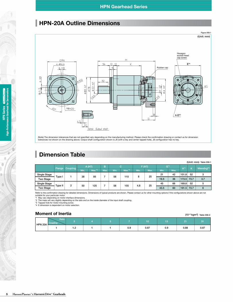
HPN-20A Outline Dimensions
Dimension Table
HPN Gearhead Series
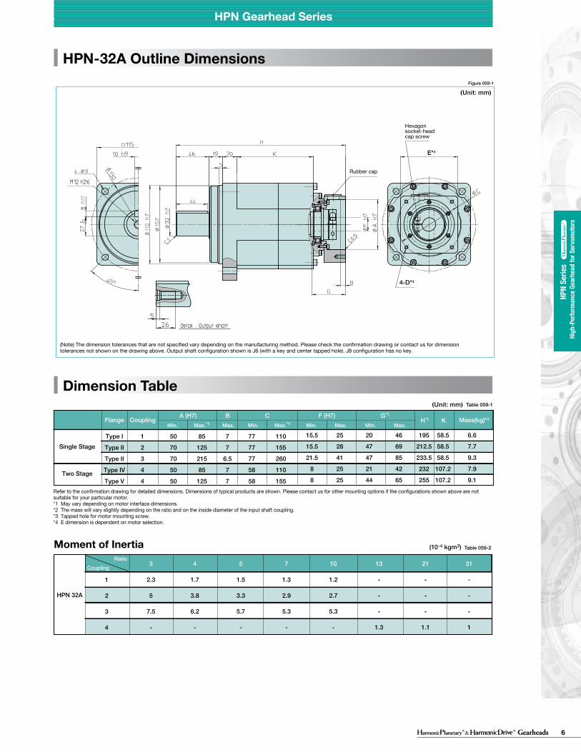
HPN-32A Outline Dimensions
Dimension Table
HPN Gearhead Series
HPN
serie
s
HPN
serie
s
Rubber cap
Hexagon socket-head cap screw
(Note) The dimension tolerances that are not specified vary depending on the manufacturing method. Please check the confirmation drawing or contact us for dimension tolerances not shown on the drawing above. Output shaft configuration shown is J6 (with a key and center tapped hole). J8 configuration has no key.
(Note) The dimension tolerances that are not specified vary depending on the manufacturing method. Please check the confirmation drawing or contact us for dimension tolerances not shown on the drawing above. Output shaft configuration shown is J6 (with a key and center tapped hole). J8 configuration has no key.
E*4
4-D*3
E*4
4-D*3
(Unit: mm)
(Unit: mm)
(Unit: mm)
Moment of Inertia Table 058-2
3
1.2
4
1
5
1
7
0.9
10
0.87
13
0.9
21
0.88
31
0.871HPN 20A
Refer to the confirmation drawing for detailed dimensions. Dimensions of typical products are shown. Please contact us for other mounting options if the configurations shown above are not suitable for your particular motor. *1 May vary depending on motor interface dimensions. *2 The mass will vary slightly depending on the ratio and on the inside diameter of the input shaft coupling.*3 Tapped hole for motor mounting screw.*4 E dimension is dependent on motor selection.
Moment of Inertia
Refer to the confirmation drawing for detailed dimensions. Dimensions of typical products are shown. Please contact us for other mounting options if the configurations shown above are not suitable for your particular motor. *1 May vary depending on motor interface dimensions. *2 The mass will vary slightly depending on the ratio and on the inside diameter of the input shaft coupling.*3 Tapped hole for motor mounting screw.*4 E dimension is dependent on motor selection.
Table 059-2
3
2.3
5
7.5
-
4
1.7
3.8
6.2
-
5
1.5
3.3
5.7
-
7
1.3
2.9
5.3
-
10
1.2
2.7
5.3
-
13
-
-
-
1.3
21
-
-
-
1.1
31
-
-
-
1
1
2
3
4
HPN 32A
Table 059-1(Unit: mm)
(10-4 kgm2)
(10-4 kgm2)
CouplingRatio
38 85 7 58 110
50 125 7 58 155
B
Type I
Type II
1
2
A (H7)Flange Coupling
CMin. Max.*1 Max. Min. Max.*1
Single Stage
Single StageTwo Stage
Two Stage
G*1
8 25151.8
173.5
169.8
191.5
21
19.5
45
43.5
42
36
66
60
52
73.7
52
73.7
3
3.7
5
6
F (H7)H*1
Min. Max. Min. Max.
4.8 25
K Mass(kg)*2BA (H7)
Flange CouplingC
Min. Max.*1 Max. Min. Max.*1
Single Stage
Two Stage
G*1
15.5
15.5
21.5
8
8
25
28
41
25
25
20
47
47
21
44
46
69
85
42
65
195
212.5
233.5
232
255
58.5
58.5
58.5
107.2
107.2
6.6
7.7
9.3
7.9
9.1
F (H7)H*1
Min. Max. Min. Max.K Mass(kg)*2
Type I
Type II
Type II
Type IV
Type V
1
2
3
4
4
50
70
70
50
50
85
125
215
85
125
7
7
6.5
7
7
77
77
77
58
58
110
155
260
110
155
Rubber cap
Hexagon socket-head cap screw
CouplingRatio
6Gearheads
HPN
Serie
sHi
gh-P
erfo
rman
ce G
earh
ead
for S
ervo
mot
ors
HPN
Serie
sHi
gh-P
erfo
rman
ce G
earh
ead
for S
ervo
mot
ors
HPN Gearhead Series
Figure 058-1 Figure 059-1
Table 058-1
HPN-20A Outline Dimensions
Dimension Table
HPN Gearhead Series
HPN-32A Outline Dimensions
Dimension Table
HPN Gearhead Series
HPN
serie
s
HPN
serie
s
Rubber cap
Hexagon socket-head cap screw
(Note) The dimension tolerances that are not specified vary depending on the manufacturing method. Please check the confirmation drawing or contact us for dimension tolerances not shown on the drawing above. Output shaft configuration shown is J6 (with a key and center tapped hole). J8 configuration has no key.
(Note) The dimension tolerances that are not specified vary depending on the manufacturing method. Please check the confirmation drawing or contact us for dimension tolerances not shown on the drawing above. Output shaft configuration shown is J6 (with a key and center tapped hole). J8 configuration has no key.
E*4
4-D*3
E*4
4-D*3
(Unit: mm)
(Unit: mm)
(Unit: mm)
Moment of Inertia Table 058-2
3
1.2
4
1
5
1
7
0.9
10
0.87
13
0.9
21
0.88
31
0.871HPN 20A
Refer to the confirmation drawing for detailed dimensions. Dimensions of typical products are shown. Please contact us for other mounting options if the configurations shown above are not suitable for your particular motor. *1 May vary depending on motor interface dimensions. *2 The mass will vary slightly depending on the ratio and on the inside diameter of the input shaft coupling.*3 Tapped hole for motor mounting screw.*4 E dimension is dependent on motor selection.
Moment of Inertia
Refer to the confirmation drawing for detailed dimensions. Dimensions of typical products are shown. Please contact us for other mounting options if the configurations shown above are not suitable for your particular motor. *1 May vary depending on motor interface dimensions. *2 The mass will vary slightly depending on the ratio and on the inside diameter of the input shaft coupling.*3 Tapped hole for motor mounting screw.*4 E dimension is dependent on motor selection.
Table 059-2
3
2.3
5
7.5
-
4
1.7
3.8
6.2
-
5
1.5
3.3
5.7
-
7
1.3
2.9
5.3
-
10
1.2
2.7
5.3
-
13
-
-
-
1.3
21
-
-
-
1.1
31
-
-
-
1
1
2
3
4
HPN 32A
Table 059-1(Unit: mm)
(10-4 kgm2)
(10-4 kgm2)
CouplingRatio
38 85 7 58 110
50 125 7 58 155
B
Type I
Type II
1
2
A (H7)Flange Coupling
CMin. Max.*1 Max. Min. Max.*1
Single Stage
Single StageTwo Stage
Two Stage
G*1
8 25151.8
173.5
169.8
191.5
21
19.5
45
43.5
42
36
66
60
52
73.7
52
73.7
3
3.7
5
6
F (H7)H*1
Min. Max. Min. Max.
4.8 25
K Mass(kg)*2BA (H7)
Flange CouplingC
Min. Max.*1 Max. Min. Max.*1
Single Stage
Two Stage
G*1
15.5
15.5
21.5
8
8
25
28
41
25
25
20
47
47
21
44
46
69
85
42
65
195
212.5
233.5
232
255
58.5
58.5
58.5
107.2
107.2
6.6
7.7
9.3
7.9
9.1
F (H7)H*1
Min. Max. Min. Max.K Mass(kg)*2
Type I
Type II
Type II
Type IV
Type V
1
2
3
4
4
50
70
70
50
50
85
125
215
85
125
7
7
6.5
7
7
77
77
77
58
58
110
155
260
110
155
Rubber cap
Hexagon socket-head cap screw
CouplingRatio
7 Gearheads
HPN
Serie
sHi
gh-P
erfo
rman
ce G
earh
ead
for S
ervo
mot
ors
HPN
Serie
sHi
gh-P
erfo
rman
ce G
earh
ead
for S
ervo
mot
ors
HPN Gearhead Series
Performance
Rating TablePlease contact our sales office if you have any questions about our specifications or comparison with another company's products.
457
10162030
3*2
457
10132131
3*2
457
10132131
< 5
< 7
< 5
< 7
< 5
< 7
< 56*2
< 58*2
< 60*2
1
2
1
2
1
2
11
14
20
Number of StagesSize Reduction
RatioBacklash
arc min
Noise*1
dB 3*2
457
10132131
3*2
457
10132131
< 5
< 7
< 5
< 7
< 63*2
< 65*2
1
2
1
2
32
40
Number of StagesSize Reduction
RatioBacklash
arc min
Noise*1
dB
*1: Rated torque is based on L50 life of 20,000 hours at rated input speed.*2: The limit for torque during start and stop cycles.*3: The limit for torque during emergency stops or from external shock loads. Always operate below this value. Calculate the number of permissible events to ensure it meets required operating conditions. *4: Maximum average input speed is limited by heat generation in the speed reducer assuming a continuous operating speed or the average input speed of a motion profile. The actual limit for average input speed depends on the operating environment.*5: Maximum instantaneous input speed.*6: The load at which the output bearing will have 20,000 hour life at the rated input speed. (Axial load = 0 and radial load point is in the center of the output shaft.)*7: The load at which the output bearing life will be 20,000 hours at the rated input speed. (Radial load = 0 and axial load point is in the center of the output shaft.)
*1: The above noise values are reference values.*2: Contact us for noise values for sizes with a reduction ratio of 3.
Table 055-1
Table 055-2 Table 055-3
Figure 060-1
Table 060-1
HPN-40A Outline Dimensions
Dimension Table
Rubber cap
Hexagon socket-head cap screw
HPN Gearhead Series HPN Gearhead Series
(Note) The dimension tolerances that are not specified vary depending on the manufacturing method. Please check the confirmation drawing or contact us for dimension tolerances not shown on the drawing above. Output shaft configuration shown is J6 (with a key and center tapped hole). J8 configuration has no key.
E*4
4-D*3
457
101620303457
101321313457
101321313457
101321313457
10132131
14 14 11 9
18 22 25 22 28 29 30 18 30 30 30 51 80 80 80 54 80 80 80
153 198 200 200 185 200 200 200 440 460 480 510 480 530 620 700
14 16 11 9
24 24 26 25 50 50 37 18 43 50 38 74
130 149 113 54
130 147 113 254 376 376 376 185 376 376 376 752 752 752 752 509 752 752 752
40 40 40 40 40 40 40 89
110 107 100 79
106 99
101 226 256 256 256 216 256 256 256 625 625 625 625 625 625 625 625
1,137 1,265 1,265 829 829 823
1,029 1,097
240260280320360400480380420450510570630740840830920
1,0001,1001,2301,3501,6001,8001,8001,9002,0002,3002,6002,9003,4003,9002,8003,1003,4003,8004,2004,5005,0005,500
280320360420460560640340380410480580630780900900
1,1001,2001,4001,6001,8502,1002,2002,0002,3002,5002,9003,2003,6003,8003,8002,7003,0003,3003,8004,2004,5005,0005,400
3,000
3,000
3,000
3,000
3,000
10,000
6,000
6,000
6,000
6,000
1
2
1
2
1
2
1
2
1
2
11
14
20
32
40
Number of StagesSize Ratio
Rated Torque ※1
Nm
Limit for Repeated Peak Torque ※2
Nm
Limit for Momentary Peak Torque ※3
Nm
Max. AverageRated Input Speed※4
rpm
Max. Input Speed (grease) ※5
rpm
Allowable Radial Load ※6
N
Allowable Axial Load ※7
N
0.060
0.27
0.77
20
93
260
Torsional Stiffness
kgfm/arc-min X100N•m/rad
2.8
4.2
940
1430
Torsional Stiffness
kgfm/arc-min X100N•m/rad
Moment of Inertia
Refer to the confirmation drawing for detailed dimensions. Dimensions of typical products are shown. Please contact us for other mounting options if the configurations shown above are not suitable for your particular motor. *1 May vary depending on motor interface dimensions. *2 The mass will vary slightly depending on the ratio and on the inside diameter of the input shaft coupling.*3 Tapped hole for motor mounting screw.*4 E dimension is dependent on motor selection.
Table 060-2
3
14
15
10.2
-
-
4
9.1
11
6.9
-
-
5
7.3
8.8
5.4
-
-
7
6.2
7.3
4.1
-
-
10
5.4
6.5
3.4
-
-
13
-
-
-
4.5
7
21
-
-
-
3.5
6
31
-
-
-
3.4
5.8
1
2
3
4
5
HPN 40A
(Unit: mm)
(Unit: mm)
(10-4 kgm2)
CouplingRatio
BA (H7)Flange Coupling
CMin. Max.*1 Max. Min. Max.*1
Single Stage
Two Stage
G*1
15.5
15.5
15.5
15.5
21.5
41
42
24
28
41
34.5
39
47
47
47
72
105
77
69
85
295.5
328.5
282.5
309.5
348
81
81
81
126
126
17
16
13
17
18
F (H7)H*1
Min. Max. Min. Max.K Mass(kg)*2
Type I
Type II
Type III
Type IV
Type V
1
2
3
4
5
70
70
70
70
70
215
175
125
125
215
6.5
6.5
7
7
6.5
78
78
78
78
77
260
225
155
155
260
HPN
serie
s
HPN
serie
s
8Gearheads
HPN
Serie
sHi
gh-P
erfo
rman
ce G
earh
ead
for S
ervo
mot
ors
HPN
Serie
sHi
gh-P
erfo
rman
ce G
earh
ead
for S
ervo
mot
ors
HPN Gearhead Series
OK
OK
OK
OK
OK
OK
NG
NG
NG
NG
NG
NG
The model number is confirmed.
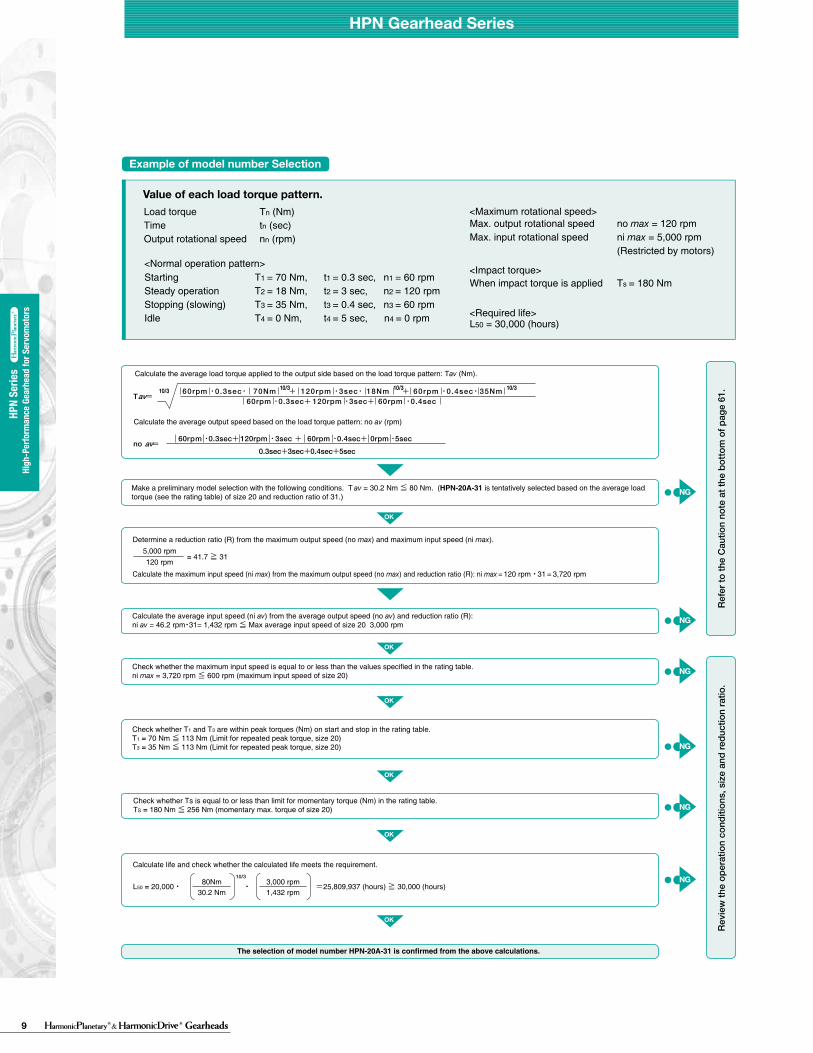
Example of model number Selection
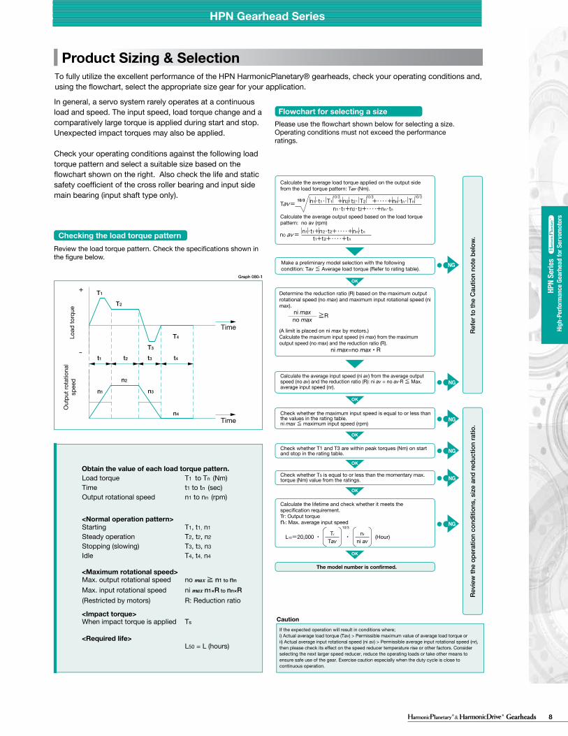
Review the load torque pattern. Check the specifications shown in the figure below.
Please use the flowchart shown below for selecting a size.Operating conditions must not exceed the performanceratings.
Checking the load torque pattern
Flowchart for selecting a size
Obtain the value of each load torque pattern.Load torque T1 to Tn (Nm)Time t1 to tn (sec)Output rotational speed n1 to nn (rpm)
<Maximum rotational speed>Max. output rotational speed no max ≧ n1 to nn
Max. input rotational speed ni max n1×R to nn×R
(Restricted by motors) R: Reduction ratio
<Impact torque>When impact torque is applied Ts
<Required life> L50 = L (hours)
<Normal operation pattern>Starting T1, t1, n1
Steady operation T2, t2, n2
Stopping (slowing) T3, t3, n3
Idle T4, t4, n4
T1
T2
T3
T4
t1
n1
n2
n3
n4
t2 t3 t4
+
−
Time
Time
Load
torq
ueO
utpu
t rot
atio
nal
spee
d
CautionIf the expected operation will result in conditions where;i) Actual average load torque (Tav) > Permissible maximum value of average load torque orii) Actual average input rotational speed (ni av) > Permissible average input rotational speed (nr), then please check its effect on the speed reducer temperature rise or other factors. Consider selecting the next larger speed reducer, reduce the operating loads or take other means to ensure safe use of the gear. Exercise caution especially when the duty cycle is close to continuous operation.
Product Sizing & SelectionTo fully utilize the excellent performance of the HPN HarmonicPlanetary® gearheads, check your operating conditions and, using the flowchart, select the appropriate size gear for your application.
Graph 080-1 T = av 60rpm ・0.3sec+ 120rpm ・3sec+ 60rpm ・0.4sec60rpm ・0.3sec・ 70Nm + 120rpm ・3sec・ 18Nm + 60rpm ・0.4sec・ 35Nm 10/3 10/3 10/3 10/3
60rpm ・0.3sec+ 120rpm ・3sec + 60rpm ・0.4sec+ 0rpm ・5sec
0.3sec+3sec+0.4sec+5secno = av
Calculate the average load torque applied to the output side based on the load torque pattern: Tav (Nm).
Calculate the average output speed based on the load torque pattern: no av (rpm)
Refe
r to
the
Cau
tion
note
bel
ow.
Revi
ew th
e op
erat
ion
cond
ition
s, s
ize
and
redu
ctio
n ra
tio.
Calculate the average load torque applied on the output side from the load torque pattern: Tav (Nm).
Calculate the average output speed based on the load torque pattern: no av (rpm)
Make a preliminary model selection with the following condition: Tav ≦ Average load torque (Refer to rating table).
Determine the reduction ratio (R) based on the maximum output rotational speed (no max) and maximum input rotational speed (ni max).
(A limit is placed on ni max by motors.)Calculate the maximum input speed (ni max) from the maximum output speed (no max) and the reduction ratio (R).
ni max=no max • R
ni maxno max ≧R
L10=20,000 ・ ・ (Hour)
10/3
Tr
Tavnr
ni av
Value of each load torque pattern.
Max. output rotational speed no max = 120 rpmMax. input rotational speed ni max = 5,000 rpm
(Restricted by motors)
When impact torque is applied Ts = 180 Nm
<Required life>
<Impact torque>
<Maximum rotational speed>
L50 = 30,000 (hours)
Starting T1 = 70 Nm, t1 = 0.3 sec, n1 = 60 rpmSteady operation T2 = 18 Nm, t2 = 3 sec, n2 = 120 rpmStopping (slowing) T3 = 35 Nm, t3 = 0.4 sec, n3 = 60 rpmIdle T4 = 0 Nm, t4 = 5 sec, n4 = 0 rpm
NG
NG
NG
NG
NG
NG
OK
OK
OK
OK
OK
OK
Check whether Ts is equal to or less than limit for momentary torque (Nm) in the rating table.TS = 180 Nm ≦ 256 Nm (momentary max. torque of size 20)
Make a preliminary model selection with the following conditions. T av = 30.2 Nm ≦ 80 Nm. (HPN-20A-31 is tentatively selected based on the average load torque (see the rating table) of size 20 and reduction ratio of 31.)
5,000 rpm120 rpm
= 41.7 ≧ 31
Determine a reduction ratio (R) from the maximum output speed (no max) and maximum input speed (ni max).
Calculate the maximum input speed (ni max) from the maximum output speed (no max) and reduction ratio (R): ni max = 120 rpm・31 = 3,720 rpm
Calculate the average input speed (ni av) from the average output speed (no av) and reduction ratio (R):ni av = 46.2 rpm・31= 1,432 rpm ≦ Max average input speed of size 20 3,000 rpm
Check whether the maximum input speed is equal to or less than the values specified in the rating table. ni max = 3,720 rpm ≦ 600 rpm (maximum input speed of size 20)
Check whether T1 and T3 are within peak torques (Nm) on start and stop in the rating table.T1 = 70 Nm ≦ 113 Nm (Limit for repeated peak torque, size 20)T3 = 35 Nm ≦ 113 Nm (Limit for repeated peak torque, size 20)
L50 = 20,000・ 10/3
80Nm30.2 Nm
3,000 rpm1,432 rpm
・ =25,809,937 (hours) ≧ 30,000 (hours)
Calculate life and check whether the calculated life meets the requirement.
The selection of model number HPN-20A-31 is confirmed from the above calculations.
Refe
r to
the
Cau
tion
note
at t
he b
otto
m o
f pag
e 61
.Re
view
the
oper
atio
n co
nditi
ons,
siz
e an
d re
duct
ion
ratio
.
In general, a servo system rarely operates at a continuous load and speed. The input speed, load torque change and a comparatively large torque is applied during start and stop. Unexpected impact torques may also be applied.
Check your operating conditions against the following load torque pattern and select a suitable size based on the flowchart shown on the right. Also check the life and static safety coefficient of the cross roller bearing and input side main bearing (input shaft type only).
Calculate the average input speed (ni av) from the average output speed (no av) and the reduction ratio (R): ni av = no av·R ≦ Max. average input speed (nr).
Check whether the maximum input speed is equal to or less than the values in the rating table. ni max ≦ maximum input speed (rpm)
Check whether T1 and T3 are within peak torques (Nm) on start and stop in the rating table.
Check whether TS is equal to or less than the momentary max. torque (Nm) value from the ratings.
Calculate the lifetime and check whether it meets the specification requirement.Tr: Output torquenr: Max. average input speed
<Normal operation pattern>
Load torque Tn (Nm)Time tn (sec)Output rotational speed nn (rpm)
NG
NG
NG
NG
NG
9 Gearheads
HPN
Serie
sHi
gh-P
erfo
rman
ce G
earh
ead
for S
ervo
mot
ors
HPN
Serie
sHi
gh-P
erfo
rman
ce G
earh
ead
for S
ervo
mot
ors
HPN Gearhead Series
OK
OK
OK
OK
OK
OK
NG
NG
NG
NG
NG
NG
The model number is confirmed.
Example of model number Selection
Review the load torque pattern. Check the specifications shown in the figure below.
Please use the flowchart shown below for selecting a size.Operating conditions must not exceed the performanceratings.
Checking the load torque pattern
Flowchart for selecting a size
Obtain the value of each load torque pattern.Load torque T1 to Tn (Nm)Time t1 to tn (sec)Output rotational speed n1 to nn (rpm)
<Maximum rotational speed>Max. output rotational speed no max ≧ n1 to nn
Max. input rotational speed ni max n1×R to nn×R
(Restricted by motors) R: Reduction ratio
<Impact torque>When impact torque is applied Ts
<Required life> L50 = L (hours)
<Normal operation pattern>Starting T1, t1, n1
Steady operation T2, t2, n2
Stopping (slowing) T3, t3, n3
Idle T4, t4, n4
T1
T2
T3
T4
t1
n1
n2
n3
n4
t2 t3 t4
+
−
Time
Time
Load
torq
ueO
utpu
t rot
atio
nal
spee
d
CautionIf the expected operation will result in conditions where;i) Actual average load torque (Tav) > Permissible maximum value of average load torque orii) Actual average input rotational speed (ni av) > Permissible average input rotational speed (nr), then please check its effect on the speed reducer temperature rise or other factors. Consider selecting the next larger speed reducer, reduce the operating loads or take other means to ensure safe use of the gear. Exercise caution especially when the duty cycle is close to continuous operation.
Product Sizing & SelectionTo fully utilize the excellent performance of the HPN HarmonicPlanetary® gearheads, check your operating conditions and, using the flowchart, select the appropriate size gear for your application.
Graph 080-1 T = av 60rpm ・0.3sec+ 120rpm ・3sec+ 60rpm ・0.4sec60rpm ・0.3sec・ 70Nm + 120rpm ・3sec・ 18Nm + 60rpm ・0.4sec・ 35Nm 10/3 10/3 10/3 10/3
60rpm ・0.3sec+ 120rpm ・3sec + 60rpm ・0.4sec+ 0rpm ・5sec
0.3sec+3sec+0.4sec+5secno = av
Calculate the average load torque applied to the output side based on the load torque pattern: Tav (Nm).
Calculate the average output speed based on the load torque pattern: no av (rpm)
Refe
r to
the
Cau
tion
note
bel
ow.
Revi
ew th
e op
erat
ion
cond
ition
s, s
ize
and
redu
ctio
n ra
tio.
Calculate the average load torque applied on the output side from the load torque pattern: Tav (Nm).
Calculate the average output speed based on the load torque pattern: no av (rpm)
Make a preliminary model selection with the following condition: Tav ≦ Average load torque (Refer to rating table).
Determine the reduction ratio (R) based on the maximum output rotational speed (no max) and maximum input rotational speed (ni max).
(A limit is placed on ni max by motors.)Calculate the maximum input speed (ni max) from the maximum output speed (no max) and the reduction ratio (R).
ni max=no max • R
ni maxno max ≧R
L10=20,000 ・ ・ (Hour)
10/3
Tr
Tavnr
ni av
Value of each load torque pattern.
Max. output rotational speed no max = 120 rpmMax. input rotational speed ni max = 5,000 rpm
(Restricted by motors)
When impact torque is applied Ts = 180 Nm
<Required life>
<Impact torque>
<Maximum rotational speed>
L50 = 30,000 (hours)
Starting T1 = 70 Nm, t1 = 0.3 sec, n1 = 60 rpmSteady operation T2 = 18 Nm, t2 = 3 sec, n2 = 120 rpmStopping (slowing) T3 = 35 Nm, t3 = 0.4 sec, n3 = 60 rpmIdle T4 = 0 Nm, t4 = 5 sec, n4 = 0 rpm
NG
NG
NG
NG
NG
NG
OK
OK
OK
OK
OK
OK
Check whether Ts is equal to or less than limit for momentary torque (Nm) in the rating table.TS = 180 Nm ≦ 256 Nm (momentary max. torque of size 20)
Make a preliminary model selection with the following conditions. T av = 30.2 Nm ≦ 80 Nm. (HPN-20A-31 is tentatively selected based on the average load torque (see the rating table) of size 20 and reduction ratio of 31.)
5,000 rpm120 rpm
= 41.7 ≧ 31
Determine a reduction ratio (R) from the maximum output speed (no max) and maximum input speed (ni max).
Calculate the maximum input speed (ni max) from the maximum output speed (no max) and reduction ratio (R): ni max = 120 rpm・31 = 3,720 rpm
Calculate the average input speed (ni av) from the average output speed (no av) and reduction ratio (R):ni av = 46.2 rpm・31= 1,432 rpm ≦ Max average input speed of size 20 3,000 rpm
Check whether the maximum input speed is equal to or less than the values specified in the rating table. ni max = 3,720 rpm ≦ 600 rpm (maximum input speed of size 20)
Check whether T1 and T3 are within peak torques (Nm) on start and stop in the rating table.T1 = 70 Nm ≦ 113 Nm (Limit for repeated peak torque, size 20)T3 = 35 Nm ≦ 113 Nm (Limit for repeated peak torque, size 20)
L50 = 20,000・ 10/3
80Nm30.2 Nm
3,000 rpm1,432 rpm
・ =25,809,937 (hours) ≧ 30,000 (hours)
Calculate life and check whether the calculated life meets the requirement.
The selection of model number HPN-20A-31 is confirmed from the above calculations.
Refe
r to
the
Cau
tion
note
at t
he b
otto
m o
f pag
e 61
.Re
view
the
oper
atio
n co
nditi
ons,
siz
e an
d re
duct
ion
ratio
.
In general, a servo system rarely operates at a continuous load and speed. The input speed, load torque change and a comparatively large torque is applied during start and stop. Unexpected impact torques may also be applied.
Check your operating conditions against the following load torque pattern and select a suitable size based on the flowchart shown on the right. Also check the life and static safety coefficient of the cross roller bearing and input side main bearing (input shaft type only).
Calculate the average input speed (ni av) from the average output speed (no av) and the reduction ratio (R): ni av = no av·R ≦ Max. average input speed (nr).
Check whether the maximum input speed is equal to or less than the values in the rating table. ni max ≦ maximum input speed (rpm)
Check whether T1 and T3 are within peak torques (Nm) on start and stop in the rating table.
Check whether TS is equal to or less than the momentary max. torque (Nm) value from the ratings.
Calculate the lifetime and check whether it meets the specification requirement.Tr: Output torquenr: Max. average input speed
<Normal operation pattern>
Load torque Tn (Nm)Time tn (sec)Output rotational speed nn (rpm)
NG
NG
NG
NG
NG
2 3
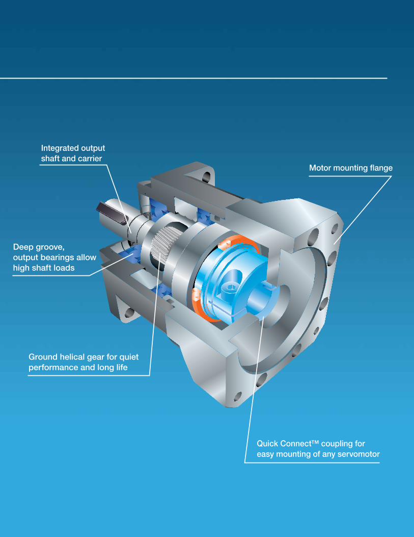
Ground helical gear for quiet performance and long life
Deep groove, output bearings allow high shaft loads
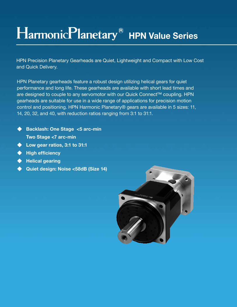
HPN Value Series
HPN Precision Planetary Gearheads are Quiet, Lightweight and Compact with Low Cost and Quick Delivery.
HPN Planetary gearheads feature a robust design utilizing helical gears for quiet performance and long life. These gearheads are available with short lead times and are designed to couple to any servomotor with our Quick Connect™ coupling. HPN gearheads are suitable for use in a wide range of applications for precision motion control and positioning. HPN Harmonic Planetary® gears are available in 5 sizes: 11, 14, 20, 32, and 40, with reduction ratios ranging from 3:1 to 31:1.
◆ Backlash: One Stage <5 arc-min Two Stage <7 arc-min◆ Low gear ratios, 3:1 to 31:1◆ High efficiency ◆ Helical gearing◆ Quiet design: Noise <58dB (Size 14)
Motor mounting flange
Integrated output shaft and carrier
Quick Connect™ coupling for easy mounting of any servomotor
2 3
Ground helical gear for quiet performance and long life
Deep groove, output bearings allow high shaft loads
HPN Value Series
HPN Precision Planetary Gearheads are Quiet, Lightweight and Compact with Low Cost and Quick Delivery.
HPN Planetary gearheads feature a robust design utilizing helical gears for quiet performance and long life. These gearheads are available with short lead times and are designed to couple to any servomotor with our Quick Connect™ coupling. HPN gearheads are suitable for use in a wide range of applications for precision motion control and positioning. HPN Harmonic Planetary® gears are available in 5 sizes: 11, 14, 20, 32, and 40, with reduction ratios ranging from 3:1 to 31:1.
◆ Backlash: One Stage <5 arc-min Two Stage <7 arc-min◆ Low gear ratios, 3:1 to 31:1◆ High efficiency ◆ Helical gearing◆ Quiet design: Noise <58dB (Size 14)
Motor mounting flange
Integrated output shaft and carrier
Quick Connect™ coupling for easy mounting of any servomotor
12 GearheadsRev 03-15
Group Companies Harmonic Drive Systems, Inc. 6-25-3 Minami-Ohi, Shinagawa-ku Tokyo 141-0013, Japan
Harmonic Drive AG Hoenbergstrasse, 14, D-6555 Limburg/Lahn Germany
Harmonic Drive® and HarmonicPlanetary® are registered trademarks and Quick Connect is a trademark of Harmonic Drive LLC. All other trade-marks are property of their respective owners.
Harmonic Drive LLCBoston US Headquarters247 Lynnfield Street Peabody, MA 01960
New York Sales Office100 Motor ParkwaySuite 116Hauppauge, NY 11788
California Sales Office333 W. San Carlos Street Suite 1070San Jose, CA 95110
Chicago Sales Office137 N. Oak Park Ave., Suite 410Oak Park, IL 60301
T: 800.921.3332 T: 978.532.1800 F: 978.532.9406
www.HarmonicDrive.net