hplc - knauer - science together · connector assignment ... detection via refractive in dex is...
TRANSCRIPT

HPLCHPLC
Detector RID 2.1L / RID 2.1L HighFlowInstructions
Document Nr. V6750

Note: For your own safety, read the instructions and observe the warnings and safety information on the device and in the instructions. Keep the instructions for future reference.
Manuel en français: Si jamais vous préfériez un manuel en français pour ce produit, veuillez vous contacter le support technique (Technical Support) par email ou par fax avec le no. de série. Merci beaucoup.
Technical Support: Phone: Fax:
+49 30 809727-111 (9-17h, Central European Time)+49 30 8015010
E-Mail: [email protected]: German, English
Publisher: KNAUER Wissenschaftliche Geräte GmbHHegauer Weg 38D-14163 BerlinPhone: +49 30 809727-0 Fax: +49 30 8015010 Internet: www.knauer.netE-Mail: [email protected]
Version information: Article number: V6750Version number: 2.0Last update: 2018/01/12Original edition
The information in this document is subject to change without prior notice. For latest version of the instructions, check our website: www.knauer.net/knowledge
Copyright: This document contains confidential information and may not be repro-duced without written content of KNAUER Wissenschaftliche Geräte GmbH.
© KNAUER Wissenschaftliche Geräte GmbH 2018All rights reserved.
AZURA® is a registered trademark of KNAUER Wissenschaftliche Geräte GmbH.

Table of contents
Table of contents
Product information . . . . . . . . . . . . . . . . . . . . . . . . . . . . . . . . . . . . . . . . . . . . . . . . . . . . . . . . . . . . . . . 1Intended use . . . . . . . . . . . . . . . . . . . . . . . . . . . . . . . . . . . . . . . . . . . . . . . . . . . . . . . . . . . . . . . . . . . 1
Operating ranges . . . . . . . . . . . . . . . . . . . . . . . . . . . . . . . . . . . . . . . . . . . . . . . . . . . . . . . . . . . . . 1Views . . . . . . . . . . . . . . . . . . . . . . . . . . . . . . . . . . . . . . . . . . . . . . . . . . . . . . . . . . . . . . . . . . . . . . . . . . 2
Front view . . . . . . . . . . . . . . . . . . . . . . . . . . . . . . . . . . . . . . . . . . . . . . . . . . . . . . . . . . . . . . . . . . . 2Rear view . . . . . . . . . . . . . . . . . . . . . . . . . . . . . . . . . . . . . . . . . . . . . . . . . . . . . . . . . . . . . . . . . . . . 2
Performance features . . . . . . . . . . . . . . . . . . . . . . . . . . . . . . . . . . . . . . . . . . . . . . . . . . . . . . . . . . . . 3Functional principle . . . . . . . . . . . . . . . . . . . . . . . . . . . . . . . . . . . . . . . . . . . . . . . . . . . . . . . . . . . . . 3
Detector design and optical path . . . . . . . . . . . . . . . . . . . . . . . . . . . . . . . . . . . . . . . . . . . . . . . 4Calculating the signal value . . . . . . . . . . . . . . . . . . . . . . . . . . . . . . . . . . . . . . . . . . . . . . . . . . . . 5Flow path . . . . . . . . . . . . . . . . . . . . . . . . . . . . . . . . . . . . . . . . . . . . . . . . . . . . . . . . . . . . . . . . . . . . 5
Scope of delivery . . . . . . . . . . . . . . . . . . . . . . . . . . . . . . . . . . . . . . . . . . . . . . . . . . . . . . . . . . . . . . . . . 6Basic safety instructions . . . . . . . . . . . . . . . . . . . . . . . . . . . . . . . . . . . . . . . . . . . . . . . . . . . . . . . . . . . . 6
Target group . . . . . . . . . . . . . . . . . . . . . . . . . . . . . . . . . . . . . . . . . . . . . . . . . . . . . . . . . . . . . . . . . . . 6Safety equipment . . . . . . . . . . . . . . . . . . . . . . . . . . . . . . . . . . . . . . . . . . . . . . . . . . . . . . . . . . . . . . . 6What must the user take into account? . . . . . . . . . . . . . . . . . . . . . . . . . . . . . . . . . . . . . . . . . . . . . 7
Where is use of the device prohibited? . . . . . . . . . . . . . . . . . . . . . . . . . . . . . . . . . . . . . . . . . . 7Secure decommissioning . . . . . . . . . . . . . . . . . . . . . . . . . . . . . . . . . . . . . . . . . . . . . . . . . . . . . . 7Opening the device . . . . . . . . . . . . . . . . . . . . . . . . . . . . . . . . . . . . . . . . . . . . . . . . . . . . . . . . . . . 7
Signal words . . . . . . . . . . . . . . . . . . . . . . . . . . . . . . . . . . . . . . . . . . . . . . . . . . . . . . . . . . . . . . . . . . . 8Decontamination . . . . . . . . . . . . . . . . . . . . . . . . . . . . . . . . . . . . . . . . . . . . . . . . . . . . . . . . . . . . . . . 8
Decontamination Report . . . . . . . . . . . . . . . . . . . . . . . . . . . . . . . . . . . . . . . . . . . . . . . . . . . . . . 8Symbols and signs . . . . . . . . . . . . . . . . . . . . . . . . . . . . . . . . . . . . . . . . . . . . . . . . . . . . . . . . . . . . . . . . 8Unpacking and setup . . . . . . . . . . . . . . . . . . . . . . . . . . . . . . . . . . . . . . . . . . . . . . . . . . . . . . . . . . . . . . 9
Operating environment . . . . . . . . . . . . . . . . . . . . . . . . . . . . . . . . . . . . . . . . . . . . . . . . . . . . . . . . . . 9Unpacking the detector . . . . . . . . . . . . . . . . . . . . . . . . . . . . . . . . . . . . . . . . . . . . . . . . . . . . . . . . . 10Power supply . . . . . . . . . . . . . . . . . . . . . . . . . . . . . . . . . . . . . . . . . . . . . . . . . . . . . . . . . . . . . . . . . . 10
Initial startup . . . . . . . . . . . . . . . . . . . . . . . . . . . . . . . . . . . . . . . . . . . . . . . . . . . . . . . . . . . . . . . . . . . . 11Connecting the leak management . . . . . . . . . . . . . . . . . . . . . . . . . . . . . . . . . . . . . . . . . . . . . . . 11Connecting the capillary . . . . . . . . . . . . . . . . . . . . . . . . . . . . . . . . . . . . . . . . . . . . . . . . . . . . . . . . 12
AZURA® Detector RID 2.1L . . . . . . . . . . . . . . . . . . . . . . . . . . . . . . . . . . . . . . . . . . . . . . . . . . . . 12AZURA® Detector RID 2.1L HighFlow . . . . . . . . . . . . . . . . . . . . . . . . . . . . . . . . . . . . . . . . . . . 12
Integrating the detector into the system . . . . . . . . . . . . . . . . . . . . . . . . . . . . . . . . . . . . . . . . . . 14Connecting the detector to the computer . . . . . . . . . . . . . . . . . . . . . . . . . . . . . . . . . . . . . . . . . 15
Configuring the LAN settings . . . . . . . . . . . . . . . . . . . . . . . . . . . . . . . . . . . . . . . . . . . . . . . . . 15Connecting the cables . . . . . . . . . . . . . . . . . . . . . . . . . . . . . . . . . . . . . . . . . . . . . . . . . . . . . . . 16Configuring the router . . . . . . . . . . . . . . . . . . . . . . . . . . . . . . . . . . . . . . . . . . . . . . . . . . . . . . . 16Integrating the LAN into a company network . . . . . . . . . . . . . . . . . . . . . . . . . . . . . . . . . . . . 16Controlling several systems separately in a LAN . . . . . . . . . . . . . . . . . . . . . . . . . . . . . . . . . 17
Remote control . . . . . . . . . . . . . . . . . . . . . . . . . . . . . . . . . . . . . . . . . . . . . . . . . . . . . . . . . . . . . . . . 20Connector assignment . . . . . . . . . . . . . . . . . . . . . . . . . . . . . . . . . . . . . . . . . . . . . . . . . . . . . . . 20Connecting cables to the pin header . . . . . . . . . . . . . . . . . . . . . . . . . . . . . . . . . . . . . . . . . . . 21
Integrator port . . . . . . . . . . . . . . . . . . . . . . . . . . . . . . . . . . . . . . . . . . . . . . . . . . . . . . . . . . . . . . . . . 22Operation . . . . . . . . . . . . . . . . . . . . . . . . . . . . . . . . . . . . . . . . . . . . . . . . . . . . . . . . . . . . . . . . . . . . . . . 22
Meaning of the LEDs . . . . . . . . . . . . . . . . . . . . . . . . . . . . . . . . . . . . . . . . . . . . . . . . . . . . . . . . . . . 23Default settings . . . . . . . . . . . . . . . . . . . . . . . . . . . . . . . . . . . . . . . . . . . . . . . . . . . . . . . . . . . . . . . . 24
Autozero . . . . . . . . . . . . . . . . . . . . . . . . . . . . . . . . . . . . . . . . . . . . . . . . . . . . . . . . . . . . . . . . . . . 24Temperature control . . . . . . . . . . . . . . . . . . . . . . . . . . . . . . . . . . . . . . . . . . . . . . . . . . . . . . . . . 25Signal mode . . . . . . . . . . . . . . . . . . . . . . . . . . . . . . . . . . . . . . . . . . . . . . . . . . . . . . . . . . . . . . . . 25Time constant & data rate . . . . . . . . . . . . . . . . . . . . . . . . . . . . . . . . . . . . . . . . . . . . . . . . . . . . . 25LED power factor . . . . . . . . . . . . . . . . . . . . . . . . . . . . . . . . . . . . . . . . . . . . . . . . . . . . . . . . . . . . 26
AZURA® Detector RID 2.1L / RID 2.1L HighFlow Instructions V6750

Table of contents
Extended Dynamic Range . . . . . . . . . . . . . . . . . . . . . . . . . . . . . . . . . . . . . . . . . . . . . . . . . . . . 26Analog output scaling and offset . . . . . . . . . . . . . . . . . . . . . . . . . . . . . . . . . . . . . . . . . . . . . . 27
GLP . . . . . . . . . . . . . . . . . . . . . . . . . . . . . . . . . . . . . . . . . . . . . . . . . . . . . . . . . . . . . . . . . . . . . . . . . . 27Switching on the detector . . . . . . . . . . . . . . . . . . . . . . . . . . . . . . . . . . . . . . . . . . . . . . . . . . . . . . . 28Flushing the flow cell . . . . . . . . . . . . . . . . . . . . . . . . . . . . . . . . . . . . . . . . . . . . . . . . . . . . . . . . . . . 28Activating standby . . . . . . . . . . . . . . . . . . . . . . . . . . . . . . . . . . . . . . . . . . . . . . . . . . . . . . . . . . . . . 29Switch off the detector . . . . . . . . . . . . . . . . . . . . . . . . . . . . . . . . . . . . . . . . . . . . . . . . . . . . . . . . . . 29
Functionality tests . . . . . . . . . . . . . . . . . . . . . . . . . . . . . . . . . . . . . . . . . . . . . . . . . . . . . . . . . . . . . . . . 30Troubleshooting . . . . . . . . . . . . . . . . . . . . . . . . . . . . . . . . . . . . . . . . . . . . . . . . . . . . . . . . . . . . . . . . . 30
Diagnostics . . . . . . . . . . . . . . . . . . . . . . . . . . . . . . . . . . . . . . . . . . . . . . . . . . . . . . . . . . . . . . . . . . . 30LAN . . . . . . . . . . . . . . . . . . . . . . . . . . . . . . . . . . . . . . . . . . . . . . . . . . . . . . . . . . . . . . . . . . . . . . . . . . 31Device problems . . . . . . . . . . . . . . . . . . . . . . . . . . . . . . . . . . . . . . . . . . . . . . . . . . . . . . . . . . . . . . 31System messages . . . . . . . . . . . . . . . . . . . . . . . . . . . . . . . . . . . . . . . . . . . . . . . . . . . . . . . . . . . . . . 32Proceeding with tasks after a leak . . . . . . . . . . . . . . . . . . . . . . . . . . . . . . . . . . . . . . . . . . . . . . . . 33
Maintenance and care . . . . . . . . . . . . . . . . . . . . . . . . . . . . . . . . . . . . . . . . . . . . . . . . . . . . . . . . . . . . 33User tasks and intervals . . . . . . . . . . . . . . . . . . . . . . . . . . . . . . . . . . . . . . . . . . . . . . . . . . . . . . . . . 33Checking calibration/validation . . . . . . . . . . . . . . . . . . . . . . . . . . . . . . . . . . . . . . . . . . . . . . . . . . 34Preparing the detector for storage or transport . . . . . . . . . . . . . . . . . . . . . . . . . . . . . . . . . . . . 35
Technical data . . . . . . . . . . . . . . . . . . . . . . . . . . . . . . . . . . . . . . . . . . . . . . . . . . . . . . . . . . . . . . . . . . . 35Main features . . . . . . . . . . . . . . . . . . . . . . . . . . . . . . . . . . . . . . . . . . . . . . . . . . . . . . . . . . . . . . . . . . 35Communication . . . . . . . . . . . . . . . . . . . . . . . . . . . . . . . . . . . . . . . . . . . . . . . . . . . . . . . . . . . . . . . 36General . . . . . . . . . . . . . . . . . . . . . . . . . . . . . . . . . . . . . . . . . . . . . . . . . . . . . . . . . . . . . . . . . . . . . . . 36
Chemical compatibility of wetted materials . . . . . . . . . . . . . . . . . . . . . . . . . . . . . . . . . . . . . . . . . 36General . . . . . . . . . . . . . . . . . . . . . . . . . . . . . . . . . . . . . . . . . . . . . . . . . . . . . . . . . . . . . . . . . . . . . . . 36Plastics . . . . . . . . . . . . . . . . . . . . . . . . . . . . . . . . . . . . . . . . . . . . . . . . . . . . . . . . . . . . . . . . . . . . . . . 37Non-metals . . . . . . . . . . . . . . . . . . . . . . . . . . . . . . . . . . . . . . . . . . . . . . . . . . . . . . . . . . . . . . . . . . . 38Metals . . . . . . . . . . . . . . . . . . . . . . . . . . . . . . . . . . . . . . . . . . . . . . . . . . . . . . . . . . . . . . . . . . . . . . . . 39
Repeat orders . . . . . . . . . . . . . . . . . . . . . . . . . . . . . . . . . . . . . . . . . . . . . . . . . . . . . . . . . . . . . . . . . . . 40Legal information . . . . . . . . . . . . . . . . . . . . . . . . . . . . . . . . . . . . . . . . . . . . . . . . . . . . . . . . . . . . . . . . 41
Transport damage . . . . . . . . . . . . . . . . . . . . . . . . . . . . . . . . . . . . . . . . . . . . . . . . . . . . . . . . . . . . . 41Warranty conditions . . . . . . . . . . . . . . . . . . . . . . . . . . . . . . . . . . . . . . . . . . . . . . . . . . . . . . . . . . . . 41Warranty seal . . . . . . . . . . . . . . . . . . . . . . . . . . . . . . . . . . . . . . . . . . . . . . . . . . . . . . . . . . . . . . . . . . 41Declaration of conformity . . . . . . . . . . . . . . . . . . . . . . . . . . . . . . . . . . . . . . . . . . . . . . . . . . . . . . . 41Disposal . . . . . . . . . . . . . . . . . . . . . . . . . . . . . . . . . . . . . . . . . . . . . . . . . . . . . . . . . . . . . . . . . . . . . . 42
HPLC glossary . . . . . . . . . . . . . . . . . . . . . . . . . . . . . . . . . . . . . . . . . . . . . . . . . . . . . . . . . . . . . . . . . . . 42Index . . . . . . . . . . . . . . . . . . . . . . . . . . . . . . . . . . . . . . . . . . . . . . . . . . . . . . . . . . . . . . . . . . . . . . . . . . . 44
AZURA® Detector RID 2.1L / RID 2.1L HighFlow Instructions V6750

Product information 1
Product informationThe AZURA® Detector RID 2.1L / RID 2.1L HighFlow1 is a sensitive and competitively priced differential refractometer which is suitable for detec-ting compounds with little or no UV activity such as alcohols, sugars, lipids or polymers in high concentrations.
AZURA® L features The device is a member of the AZURA® L product line and shares a num-ber of common features. Removable front cover, for optional device and/or user protection. Instrument stability through a large base area and low center gravity. The leak tray at the front side collects leaking fluids and protects com-
ponents from possible damage. LED device status indication. Thus, the user sees directly if the detector
operates correctly or if an error as occurred. Power connection and control connectors on rear of device.
Identification The device name can be found on the front panel, above the serial num-ber. A silver sticker on the rear side displays the manufacturer name and address, the product number and power supply specifications.
Note: At the time of delivery, the detector is filled with ethanol.
Intended useNote: Only use the device for applications that fall within the range of the intended use. Otherwise, the protective and safety equipment of the device could fail.
Detection via refractive index is very suitable for analytical HPLC (High Per-formance Liquid Chromatography), GPC (Gel Permeation Chromatogra-phy) and SEC (Size Exclusion Chromatography) RI detectors are extremely versatile, but the detection is made with lower sensitivity as with other detection methods. RI detectors are not suitable for gradient chromatography, because they react very sensitive to chan-ges in eluent composition. In addition, RI detectors are very dependent from temperature and pressure, and unstable conditions cause base line instability. In some cases, positive and negative peaks may occur in a single analysis. The detector is designed for research and may be not suitable for diagno-stic purposes.
Operating rangesDer AZURA® Detektor RID 2.1L can be used in the following areas for ana-lytical applications (with flow rates up to 10 ml/min): food analysis chemical analysis pharmaceutical analysis environmental analysis biochemical analysisThe AZURA® Detector RID 2.1L HighFlow can be used for preparative applications (with flow rates up to 100 ml/min). It is not suitable for analyti-cal analysis.
1. Both variants will be referred to as "detector"
AZURA® Detector RID 2.1L / RID 2.1L HighFlow Instructions V6750
2 Product information
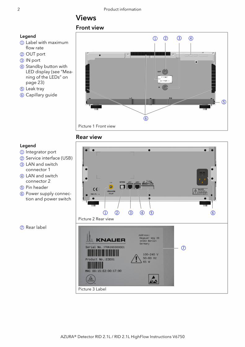
ViewsFront view
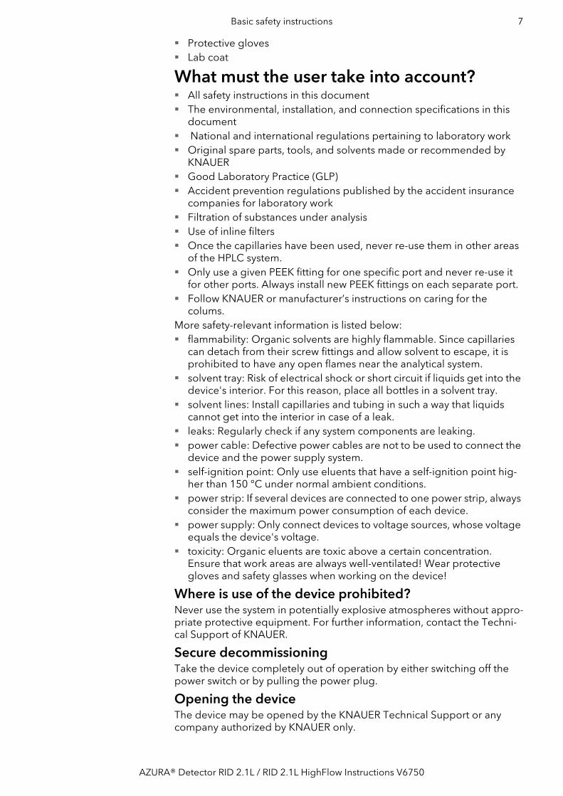
Rear view
Legend1 Label with maximum
flow rate2OUT port3 IN port4Standby button with
LED display (see “Mea-ning of the LEDs” on page 23)
5 Leak tray6Capillary guide
Picture 1 Front view
3 4
5
6
21
Legend1 Integrator port2Service interface (USB)3 LAN and switch
connector 14 LAN and switch
connector 25Pin header6Power supply connec-
tion and power switch
Picture 2 Rear view
7Rear label
Picture 3 Label
1 2 3 4 5 6
7
AZURA® Detector RID 2.1L / RID 2.1L HighFlow Instructions V6750

Product information 3
Performance featuresOptical bench The newly designed optical bench with advanced temperature control
ensures high sensitivity, fast baseline stabilization, and excellent reprodu-cibility. Furthermore, the long-life LED and highly back pressure resistant flow cell guarantee minimal maintenance.
Extended Dynamic Range
If the Extended Dynamic Range option is active, it is possible to broaden the linear dynamic range.
Data rate The detector measures with a maximum data rate of 100 Hz. During the measurement, approx. 100 spectra per second are recorded.
Control This detector can be controlled with various Chromatography Data Sys-tems (OpenLAB® EZChrom Edition, ClarityChrom®, Chromeleon®, Purity-Chrom® Bio and Mobile Control Chrom) via LAN or via analog input/out-put, allowing it to be integrated into almost any LC system.
GLP data The Mobile Control and supported software products can be used to dis-play or read out GLP data such as operating hours or light source opera-ting hours. You find a detailed description on how to display or read out GLP data in the respective instructions of the software products (https://www.knauer.net/en/Support/User-manuals).
Diagnostics Light intensity and balance, zero glass position and LED current can be easily monitored via the Mobile Control and supported software products to ensure optimal working conditions for your analysis.
AZURA® Neo The AZURA® Neo electronic platform features: A new microprocessor for faster device performance Communication interfaces: dual IP stack with switch (for connecting
AZURA devices to one another) and LAN stack function, plus USB(internal USB to RS-232) service interface. Both LAN ports (1 and 2) canbe used as interface or as switch.
Industrial standard 4–20 mA analog input (replacing 0–10 V input onthe previous electronic platform).
No external display support.
Functional principleWhen a ray of light passes from one medium into another the light is refracted or bent depending on the light ray’s speed of light and the angle of incidence. The extent to which a medium refracts light is its refractive index (RI). Snell’s law of refraction expresses the relationship between the angle of incidence and the angle of refraction.
AZURA® Detector RID 2.1L / RID 2.1L HighFlow Instructions V6750

4 Product information
Snell’s Law of refraction
whereα1 angle of incidence
α2 angle of refraction
c1 speed of light in medium 1
c2 speed of light in medium 2
c1 refractive index in medium 1
c2 refractive index in medium 2
n relative refractive index
The refractive index of a medium depends on the wavelength of the light and the density of the medium. Normally, in an RI detector, the wavelength is constant. The density depends on the temperature, pres-sure and composition of the medium.
Detector design and optical pathThe AZURA® Detector RID 2.1L HighFlow is a differential refractive index detector of the deflection type. The detector measures the deflection of a light beam causes by the difference in refractive index between the liquids in sample and reference cell compartments of the flow cell.A light beam emitted from the LED light source 1 crosses the RID’s sample and the reference cells 2 twice. When both cells contain pure sol-vent, the system is calibrated to zero by means of a parallel zero glass plate 3 which positions the beam on the two detector diodes 4 in such a manner that the measured light intensities (I1 and I2) of the two diodes are virtually identical. When the sample cell contains a solution with a different refractive index, the light beam is geometrically proportionally deflected depending on the relative change of the refractive index (according to Snell´s law).
This results in a change of the light intensities I1 and I2 (one increases and the other decreases), proportional to concentration and refractive index of the sample solution. From these intensity changes the signal value is calculated.
α1sinα2sin---------------
c1
c2------
n1
n2------ n= = =
12
3
4
AZURA® Detector RID 2.1L / RID 2.1L HighFlow Instructions V6750

Product information 5
Calculating the signal value
The light beam reaches the two detector diodes (1 and 2) which deliver the intensity values I1 and I2 during measurement, depending on the light beam’s deflection. The difference and sum of I1 and I2 are calculated con-tinuously, and the resulting signal is given out to the device’s outputs.
Flow pathAnalysis During analysis, the solvent takes the following flow path (see figure
below):1. Enters through IN port.2. Passes through heat exchanger.3. Flows through sample compartment of the flow cell.4. Passes through flush valve.5. Exits through OUT port.
Flushing process When the flush valve is activated the solvent takes the following flow path (see figure below):1. Enters through IN port.2. Passes through heat exchanger.3. Flows through sample compartment of the flow cell.4. Passes through flush valve and directed to the second heat exchanger.5. Flows through reference compartment of the flow cell.6. Exits through OUT port.
signal value
I1–I2 difference of intensity values I1+I2 sum of intensity values a autozero constant c calibration constant
signalI1 I– 2( )I1 I2+( )--------------------- a+
c×=
Legend1Solvent2Heat exchanger3Sample cell4Reference cell5Flush valve6Temperature cont-
rolled compartment7waste
1
2 3
6
4
5
7
AZURA® Detector RID 2.1L / RID 2.1L HighFlow Instructions V6750

6 Scope of delivery
Scope of deliveryNote: Only use spare parts and accessories made by KNAUER or a com-pany authorized by KNAUER.
Power supply cable Device AZURA® Detector RID 2.1L / RID 2.1L HighFlow Accessory kit AZURA® Detector RID 2.1L / RID 2.1L HighFlow Accessory kit AZURA®
Valid documents:
Instructions AZURA® Detector RID 2.1L / RID 2.1L HighFlow Installation Qualification document ("IQ") Declaration of Conformity
Basic safety instructionsTarget groupThis document address persons who are qualified as chemical laboratory technicians or have completed comparable vocational training.The following knowledge is required: Fundamental knowledge of liquid chromatography Knowledge regarding substances that are suitable only to a limited
extent for use in liquid chromatography Knowledge regarding the health risks of chemicals Participation during an installation of a device or a training by the com-
pany KNAUER or an authorized company.If you do not belong to this or a comparable professional group, you may not perform the work described in these instructions under any circum-stances. In this case, please contact your superior.
Safety equipmentWhen working with the device, take measures according to lab regula-tions and wear protective clothing: Safety glasses with side protection
Legend1Solvent2Heat exchanger3Sample cell4Reference cell5Flush valve6Temperature cont-
rolled compartment7waste
1
2 3
6
4
5
7
AZURA® Detector RID 2.1L / RID 2.1L HighFlow Instructions V6750
Basic safety instructions 7
Protective gloves Lab coat
What must the user take into account? All safety instructions in this document The environmental, installation, and connection specifications in this
document National and international regulations pertaining to laboratory work Original spare parts, tools, and solvents made or recommended by
KNAUER Good Laboratory Practice (GLP) Accident prevention regulations published by the accident insurance
companies for laboratory work Filtration of substances under analysis Use of inline filters Once the capillaries have been used, never re-use them in other areas
of the HPLC system. Only use a given PEEK fitting for one specific port and never re-use it
for other ports. Always install new PEEK fittings on each separate port. Follow KNAUER or manufacturer’s instructions on caring for the
colums.More safety-relevant information is listed below: flammability: Organic solvents are highly flammable. Since capillaries
can detach from their screw fittings and allow solvent to escape, it isprohibited to have any open flames near the analytical system.
solvent tray: Risk of electrical shock or short circuit if liquids get into thedevice's interior. For this reason, place all bottles in a solvent tray.
solvent lines: Install capillaries and tubing in such a way that liquidscannot get into the interior in case of a leak.
leaks: Regularly check if any system components are leaking. power cable: Defective power cables are not to be used to connect the
device and the power supply system. self-ignition point: Only use eluents that have a self-ignition point hig-
her than 150 °C under normal ambient conditions. power strip: If several devices are connected to one power strip, always
consider the maximum power consumption of each device. power supply: Only connect devices to voltage sources, whose voltage
equals the device's voltage. toxicity: Organic eluents are toxic above a certain concentration.
Ensure that work areas are always well-ventilated! Wear protectivegloves and safety glasses when working on the device!
Where is use of the device prohibited?Never use the system in potentially explosive atmospheres without appro-priate protective equipment. For further information, contact the Techni-cal Support of KNAUER.
Secure decommissioningTake the device completely out of operation by either switching off the power switch or by pulling the power plug.
Opening the deviceThe device may be opened by the KNAUER Technical Support or any company authorized by KNAUER only.
AZURA® Detector RID 2.1L / RID 2.1L HighFlow Instructions V6750

8 Symbols and signs
Signal wordsPossible dangers related to the device are divided into personal and material damage in these instructions.
DANGER indicates a hazardous situation which, if not avoided, will result in death or serious injury. WARNING indicates a hazardous situation which, if not avoided, could result in death or serious injury. CAUTION indicates a hazardous situation which, if not avoided, could result in minor or moderate injury.NOTICE is used to address practices not related to phy-sical injury.
DecontaminationContamination of devices with toxic, infectious or radioactive substances poses a hazard for all persons during operation, repair, sale, and disposal of a device.
Life-threatening injuriesHealth danger if getting in contact with toxic, infectious or radio-active substances. Before disposing of the device or sending it away for repair, you are
required to decontaminate the device in a technically correct manner.All contaminated devices must be properly decontaminated by a specia-list company or the operating company before they can be recommissi-oned, repaired, sold, or disposed of. All materials or fluids used for decontamination must be collected separately and disposed of properly.
Decontamination ReportDevices without a completed Decontamination Report will not be repai-red. If you would like to return a device to KNAUER, make sure to enclose a completed Decontamination Report with the device: http://www.knauer.net/en/knowledge/downloads/service.html
Symbols and signsThe following symbols and signs can be found on the device, in the chro-matography software or in the instructions:
symbols Meaning
High-voltage hazard
Electrostatic discharge hazard, damages to sys-tem, device, or components can occur.
Obey maximum load for leak tray during transpor-tation, installation and operation.
A device or system marked with CE fulfills the pro-duct specific requirements of European directives. This is confirmed in a Declaration of Conformity.
AZURA® Detector RID 2.1L / RID 2.1L HighFlow Instructions V6750

Unpacking and setup 9
Unpacking and setupBecause of its general temperature sensitivity, the detector must always be the lowest device in a system. The RI detector must always be situated below a UV detector because it is more sensible to temperature. The capillary kits for easy installation (available as accessory) only fit if the system is set up accordingly. Note: At the time of delivery, the detector is filled with ethanol. Flush the whole system (with opened flush valve) with water for 60 minutes mini-mum before you start the measures.
Operating environmentRead the technical data (see page 35) before you determine the opera-ting environment. There you find all important information about power supply, ambient conditions and air humidity.Only if the requirements for ambient conditions of the operating environ-ment are met, the intended use can be ensured. In order to ensure thermo stability and to prevent drift effects, note the following aspects: More effective aspects for detectors in HPLC systems are described in the according chapter (see “Integrating the detector into the system” on page 14).
Device defectThe device overheats at exposure to sunlight and insufficient air circula-tion. Device failures are very likely. Set up the device in such a way that it is protected against exposure to
direct sunlight. Leave some space for air circulation: See space requirements.Note: The leak sensor may malfunction if the detector is placed on a tilted surface. Check the horizontal position with a spirit level.
General requirements
Set up the detector on a flat surface. Protect the detector against direct sunlight. Set up the detector at a location not exposed to air drafts (A/C sys-
tems). Protect the detector against strong air draft. Do not set up the detector near other machines that cause floor vibra-
tions. Avoid vibration. Keep the detector away from high-frequency sources. High-frequency
sources may compromise measuring values. If you are located in an earthquake area, use the bore holes 1 in the
side panels to secure the device. The bore holes are located on both right and left side panels.
Testing seals in Canada and the USA at nationally recognized testing centers (NRTL). The certified device or system has successfully passed the qua-lity and security tests.
Notes provide useful tips or information worth knowing.
symbols Meaning
AZURA® Detector RID 2.1L / RID 2.1L HighFlow Instructions V6750

10 Unpacking and setup
Space requirements Minimum distance of 5 cm with a device on one side. Minimum distance of 10 cm with devices on both sides.
Unpacking the detectorThe detector ist delivered in a closed package. To prevent damage, the package is the best possible protection for the protector.
Prerequisite Check packaging for damage caused during transportation. If necessary, put forward any claim for damages to the carrier.
Tools Utility knife
Bruising dangerDamage to the device by carrying or lifting it on protruding housing parts. The device may fall and thus cause injuries. Lift the device only centrally on the side of the housing.
Process 1. Set up the package in such a way that you can read the label. Using the utility knife, cut the adhesive tape and open the packaging.
2. Remove the foam insert. Take out the accessory kit and the manual.3. Open the accessory kit and check the scope of delivery. In case any
parts are missing, contact the Technical Support.4. Clasp the device from below, lift it out of the packaging and place it on
its feet. Do not hold onto the front cover.5. Check the device for signs of damage that occurred during transport.
In case you notice any damage, contact the Technical Support.6. Place the device in its site of operation and remove protective foil.
Next steps Store packaging and keep the included packing list for repeat orders.
Power supplyElectronic defectElectronic hazard when using an identically constructed power adapter from another manufacturer. Only use original parts and accessories made by KNAUER or a com-
pany authorized by KNAUER.Note: Make sure that the power adapter and power supply cable meet the requirements (see “Power supply” on page 36). Detachable supply cables are not allowed to be replaced with other cable types.
The device is intended for use with AC power networks of 100-240 V. Only the supplied power supply cable is to be used to connect the
device to the power supply. Make sure that the power plug on rear of the device is always acces-
sible, so that the device can be disconnected from the power supply.
1
AZURA® Detector RID 2.1L / RID 2.1L HighFlow Instructions V6750
Initial startup 11
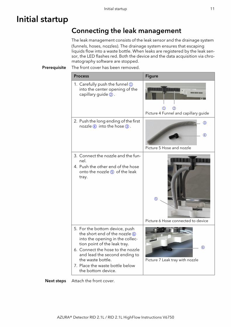
Initial startupConnecting the leak managementThe leak management consists of the leak sensor and the drainage system (funnels, hoses, nozzles). The drainage system ensures that escaping liquids flow into a waste bottle. When leaks are registered by the leak sen-sor, the LED flashes red. Both the device and the data acquisition via chro-matography software are stopped.
Prerequisite The front cover has been removed.
Next steps Attach the front cover.
Process Figure
1. Carefully push the funnel 1into the center opening of thecapillary guide 2.
Picture 4 Funnel and capillary guide
2. Push the long ending of the firstnozzle 4 into the hose 3.
Picture 5 Hose and nozzle
3. Connect the nozzle and the fun-nel.
4. Push the other end of the hoseonto the nozzle 5 of the leaktray.
Picture 6 Hose connected to device
5. For the bottom device, pushthe short end of the nozzle 6into the opening in the collec-tion point of the leak tray.
6. Connect the hose to the nozzleand lead the second ending tothe waste bottle.
7. Place the waste bottle belowthe bottom device.
Picture 7 Leak tray with nozzle
1 2
3
4
5
6
AZURA® Detector RID 2.1L / RID 2.1L HighFlow Instructions V6750

12 Initial startup
Connecting the capillaryComponent defectDamaging the threads of components caused by overtightened fittings. Pay attention to the torque values. Use 5 Nm for stainless steel fittings. Use 1 Nm for PEEK fittings.Connect the inlet capillary with the IN port and the outlet capillary with the OUT port. If the capillaries are connected incorrectly, damages at the flow cell and a reduced detector performance may occur. Note: Choose fittings which keep the dead volume at a low level, and short capillaries with a small diameter.
AZURA® Detector RID 2.1LAt the front side, both connections are designed for 1/16'' capillaries and standardized fittings. Following procedure can be appplied for both the IN port and the OUT port.
Tools Open-end wrench
Next steps Check if all fittings are tight.
AZURA® Detector RID 2.1L HighFlowAt the front side, both connections are designed for 1/4''-28 UNF flat bot-tom fittings.
Tools Open-end wrench
Component defectDamage of the flow cell of high backpressure. Install the backpressure regulator from the supplied accessory kit.
Procedure Picture
1. Push the capillary 1 through the fitting 2.
2. Attach the seal ring 3.
3. Insert the capillary as far as pos-sible into the IN port 4 or OUT port 5.
4. Tighten the fitting finger tight.
4
5
1 2 3
AZURA® Detector RID 2.1L / RID 2.1L HighFlow Instructions V6750

Initial startup 13
IN port
OUT port
Procedure Picture
1. Push the capillary 1 throughthe fitting 2.
2. Slide the lock ring 3 over thetubing. Note that the taperedend of the lock ring (with thethin edge) has to point to theseal ring 4.
3. Attach the seal ring 4.
4. Insert the capillary as far as pos-sible into the IN port 5.
5. Tighten the fitting finger tight.
Procedure Picture
1. Push the capillary 1 throughthe fitting 2.
2. Slide the lock ring 3 over thetubing. Note that the taperedend of the lock ring (with thethin edge) has to point to theseal ring 4.
3. Attach the seal ring 4.
4. Insert the capillary as far as pos-sible into the OUT port 5.
5. Tighten the fitting finger tight.
1 2 43
1 32 4
5
1 2 43
1 32 4
5
AZURA® Detector RID 2.1L / RID 2.1L HighFlow Instructions V6750

14 Initial startup
Next steps Check if all fittings are tight.
Integrating the detector into the systemTo integrate the detector into a system, note the ambient conditions found in the section operating environment (see page 9) and technical data (see page 35) as well as the ambient conditions of other devices to be integrated into that system. The detector is integrated into the HPLC flow system by connecting the capillary to the flow cell and the HPLC sys-tem. The capillary connections in a basic HPLC system are shown in the following picture.
Regarding the flow path, the refractive index detector should always be the last device in a HPLC system. The flow cell consists of glass and is very pressure sensitive. At the outlet side, back pressures may build up in the flow cell which damage the material. The pressure in the flow cell should be below 5 bar.
Prerequisite All devices are positioned accordingly.
6. Connect the capillary of the OUT port 6with the T-piece 7and tighten the fitting finger tight.
7. Connect the back pressure regulator 8 between T-piece and capillary 9which leads into a waste container. Note the arrow on the back pressure regulator which shows the flow direction.
8. Connect the capillary to the fraction collection 10 with the T-piece and tighten the fit-ting finger tight.
Procedure Picture
1 32 4
6
bl
8
9
7
AZURA® Detector RID 2.1L / RID 2.1L HighFlow Instructions V6750

Initial startup 15
Next steps Start the devices of the system. Note the specifications of the correspon-ding device instructions.
Connecting the detector to the computerThe detector can be operated with different software packages. You find more detailed information in the List of Supported Devices on the KNAUER webpage: https://www.knauer.net/Dokumente/software/sup-ported_knauer_instruments_in_knauer_software.pdfYou find a detailed description on the chromatography software in the corresponding software manual.Note: HPLC devices made by KNAUER work only with IP adresses which are assigned via IPv4. IPv6 is not supported.
This section describes how to set up an HPLC system in a local area net-work (LAN) and how a network administrator can integrate this LAN into your company network. The description applies to the operating system Windows and all conventional routers.To set up a LAN, we recommend to use a router. That means the following steps are required:
Process 1. On the computer, go to the control panel and check the LAN proper-ties.
2. Hook up the router to the devices and the computer.3. On the computer, configure the router to set up the network.4. Install the chromatography software from the data storage device.5. Switch on the device and run the chromatography software.
Configuring the LAN settingsThe LAN uses only one server (which is normally the router) from that the devices automatically receive their IP address.
Prerequisite In Windows, power saving, hibernation, standby, and screen saver must be deactived.
In case you use an USB-to-COM box, the option "Allow the computer toturn off ths device to save power" in the devicemanager must be deac-tivated for all USB hosts.
For all LAN devices: For the network adapter, the following option inthe Device Manager must be deactivated: "Allow the computer to turnoff this device to save power".
Process 1. In Windows choose Start Control Panel Network and Sharing Center.
2. Double-click on LAN Connection.3. Click on the button Properties.4. Select Internet Protocol version 4 (TCP/IPv4).5. Click on the button Properties.6. Check the settings in the tab General. The correct settings for the
DHCP client are:a) Obtain IP address automatically b) Obtain DNS server address automatically
Process Procedure
1. Connect the column outlet to the IN port.2. Connect the OUT port with the waste container or fraction collector.
For the AZURA® Detector RID 2.1L HighFlow, it is mandatory toinstall the back pressure regulator which is included in the suppliedaccessory kit.
AZURA® Detector RID 2.1L / RID 2.1L HighFlow Instructions V6750
16 Initial startup
7. Click on the button OK.
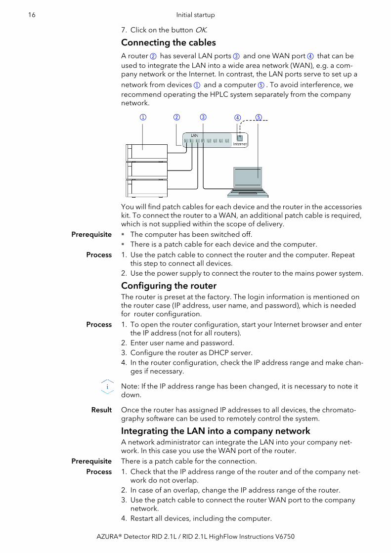
Connecting the cables A router 2 has several LAN ports 3 and one WAN port 4 that can be used to integrate the LAN into a wide area network (WAN), e.g. a com-pany network or the Internet. In contrast, the LAN ports serve to set up a network from devices 1 and a computer 5. To avoid interference, we recommend operating the HPLC system separately from the company network.
You will find patch cables for each device and the router in the accessories kit. To connect the router to a WAN, an additional patch cable is required, which is not supplied within the scope of delivery.
Prerequisite The computer has been switched off. There is a patch cable for each device and the computer.
Process 1. Use the patch cable to connect the router and the computer. Repeat this step to connect all devices.
2. Use the power supply to connect the router to the mains power system.
Configuring the routerThe router is preset at the factory. The login information is mentioned on the router case (IP address, user name, and password), which is needed for router configuration.
Process 1. To open the router configuration, start your Internet browser and enter the IP address (not for all routers).
2. Enter user name and password.3. Configure the router as DHCP server.4. In the router configuration, check the IP address range and make chan-
ges if necessary.
Note: If the IP address range has been changed, it is necessary to note it down.
Result Once the router has assigned IP addresses to all devices, the chromato-graphy software can be used to remotely control the system.
Integrating the LAN into a company networkA network administrator can integrate the LAN into your company net-work. In this case you use the WAN port of the router.
Prerequisite There is a patch cable for the connection.Process 1. Check that the IP address range of the router and of the company net-
work do not overlap.2. In case of an overlap, change the IP address range of the router.3. Use the patch cable to connect the router WAN port to the company
network.4. Restart all devices, including the computer.
1 2 3 4 5
AZURA® Detector RID 2.1L / RID 2.1L HighFlow Instructions V6750

Initial startup 17
Controlling several systems separately in a LANDevices connected to a LAN communicate through ports, which are part of the IP address. If more than one HPLC system is connected to the same LAN and you plan on controlling them separately, you can use different ports to avoid interference. Therefore, the port number for each device must be changed and this same number must be entered into the device configuration of the chromatography software. We recommend to use the same port number for all devices in the same system.
Note: The port is set to 10001 at the factory. You must use the same num-bers in the device configuration of the chromatography software as in the device, otherwise the connection fails.
Process 1. Find out port number and change it on the device.2. Enter the port number in the chromatography software.
Result The connection is established.
Note: Setting a fixed IP address.
Note: Before changing the LAN settings, inform yourself about the IT saf-ety standards valid for your laboratory.
Tow options are given to set the device IP address to fixed (static) or dyna-mic (DHCP) via software: Mobile Control or Firmware Wizard.Mobile Control: Setting a static IP addressNote: The device is factory set to a dynamic IP address (DHCP). To ensure a permanent LAN connection between the chromatography software and the device, we recommend to set a static IP address for certain applica-tions. You find further information on LAN settings in the chapter “Device Settings“ of the Mobile Control Software Instructions.
Prerequisites The device has been switched on. Mobile Control has been installed and started. The connection between the Mobile Control and the device has been
established.Procedure 1. In the Mobile Control, choose <Settings> .
2. On the <General> tab, choose the device name.3. Under <Network Settings>, choose the setting <Static> 1.4. Enter the IP address into the text box <IP Address> 2.5. If necessary, change the subnet mask and the gateway 3.6. Click in the top right corner.7. Restart the device (recommended).
Result The device is now accessible via the static IP address.
1
2
3
AZURA® Detector RID 2.1L / RID 2.1L HighFlow Instructions V6750

18 Initial startup
Mobile Control: Setting IP address to DHCP via device namePrerequisites The device has been switched on.
Mobile Control has been installed and started. The connection between the Mobile Control and the device has been
established.Procedure 1. In the Mobile Control, choose <Settings> .
2. On the <General> tab, choose the device name. 3. Under <Network Settings>, go back to the original setting by clicking
the <Reset> button.4. Click in the top right corner.5. Restart the device (recommended).
Result The device is now accessible via a dynamic IP address.Mobile Control: Setting IP address to DHCP via device serial num-ber
Prerequisites The device has been switched on. Mobile Control has been installed and started. The connection between the Mobile Control and the device has been
established.Procedure 1. In the Mobile Control, choose <Settings> .
2. Under <Network Settings>, click the <Reset> button. The window <Reset communication settings> opens.
3. Enter the serial number of the device into the text field.4. Click <OK>. 5. Restart the device (recommended).
Result The device is now set to DHCP.
Firmware Wizard: Setting a static IP addressNote: You find further information on LAN settings in the chapter “Firm-ware Wizard“ of the Mobile Control User Manual.
Prerequisites The device has been switched on. Firmware Wizard has been installed and started. The connection between Firmware Wizard and the device has been
established.Procedure 1. In Firmware Wizard, click <Reset LAN Settings...>.
AZURA® Detector RID 2.1L / RID 2.1L HighFlow Instructions V6750

Initial startup 19
2. The window <Device connection settings> opens. Enter serial number of the AZURA® device into the text field <Target device serial number> 1.
3. Select option <Use the following IP address> 2.
4. Enter the IP address into the text field <IP address> 3.5. Optionally, adjust subnet mask and gateway 4.6. Click <Reset Conn. Settings> 5to accept changes.7. Restart the device (recommended).
Result The device is now accessible via the static IP address.
Firmware Wizard: Setting an IP address to DHCPPrerequisites The device has been switched on.
Firmware Wizard has been installed and started. The connection between Firmware Wizard and the device has been
established.Procedure 1. In Firmware Wizard, click <Reset LAN Settings...>.
2. The window <Device connection settings> opens. Enter serial number of the device into the text field <Target device serial number> 1.
3. Select option <Obtain an IP address automatically> 2.
4. Click <Reset Conn. Settings> 5to accept changes.5. Restart the device (recommended).
Result The device is now set to DHCP.
Setting a static IP address via APIPATo set an IP address for a detector, it must be connected to a LAN net-work. Both LAN ports of the detector and be connected as needed with a PC and/or with any other device. Note that the other device can again connected with a third device and so on, so you may add several devices in a row.Via Mobile Control, you can set the IP address either manually or via DHCP. In addition, all devices with AZURA® Neo can be set via "router-less" APIPA configuration.To set an IP address via APIPA configuration, the PC and the LAN control must be set to DHCP mode. If no DHCP server can be detected, the device switches into APIPA configuration and receives an IP address auto-matically. This process may take several minutes.
1
2
3
4
5
AZURA® Detector RID 2.1L / RID 2.1L HighFlow Instructions V6750

20 Initial startup
Remote controlOn the rear of the valve drive are sockets on a terminal strip. Signals can be send and received by other devices via those sockets. The signals are for example start signals of an injection valve or an autosampler which is connected to the START connector. All voltages between GROUND and the corresponding input or output must be connected.
Connector assignment
Picture 8 relation between display and events terminal strip
connector Function
GND Grounding of all inputs and outputs Reference point of the voltage at the signal inputs.
EVENT 1 TTL output (default setting)/ OC with external pull-up up to 24 V (25 mA) Levels: passive 5 V active 0 V
FLUSH IN TTL Input Low activeSecure switching threshold at least 10 mAActivates or deactivates the flush valve.
GND Grounding of all inputs and outputs Reference point of the voltage at the signal inputs.
AUTOZERO IN (AZ IN)
TTL Input Low activeSecure switching threshold at least 10 mAA signal (short-circuit to ground) sets the measuring signal to zero. The measuring will be started again if the signal is switched off.
START OUT TTL output (default setting)/ OC with external pull-up up to 24 V (25 mA)Levels: passive 5 V active 0 V
AZURA® Detector RID 2.1L / RID 2.1L HighFlow Instructions V6750

Initial startup 21
Connecting cables to the pin headerTo control one device through another, you use the multi-pin connector. To use remote control, you have to connect cables to the terminal strip (both included with delivery). The single ports are used to exchange cont-rol signals.
Prerequisite The device has been turned off. The power plug has been pulled.
Tools Operating tool
Electronic defectConnecting cables to the multi-pin connector of a switched on device cau-ses a short circuit. Turn off the device before connecting cables. Pull the power plug.
Electronic defectElectrostatic discharge can destroy the electronics. Wear a protective bracelet against electrostatic discharge and ground.
START IN TTL Input Low activeSecure switching threshold at least 10 mAAfter receiving a signal (short-circuit to ground) from an external device, the detector starts. If controlled with software, an electronic trigger is send through the LAN.
ERROR OUT TTL output (default setting)/ OC with external pull-up up to 24 V (25 mA)Levels: passive 5 V active 0 VOutput is active until the error condition has been eli-minated.
ERROR IN TTL Input Low activeSecure switching threshold at least 10 mAAfter receiving a signal (short-circuit to ground) from an external device, an error message appears, and the detector stops.
VALVE 24 V Event-controlled switching of 24 V against GND.
5 V OUT Provides a voltage of 5 V with respect to GND. This makes it possible to supply a load that is switched by an EVENT.Protection: 5 V–50 mA
GND Grounding of all inputs and outputs Reference point of the voltage at the signal inputs.
connector Function
AZURA® Detector RID 2.1L / RID 2.1L HighFlow Instructions V6750

22 Operation
Process 1. Push the operating tool 3into an upper small opening on the front of the terminal strip 1.
2. Lead the cable into the opening2 below the inserted operating tool.
3. Remove the operating tool.
Next steps Check if the cables are firmly attached. Push the terminal strip onto the multi-pin connector. Finish the installation. Put the device into operation.
Integrator portThe integrator output supplies the current signal value as an analog vol-tage (0–2.5 V). Via software or Mobile Control, the signal cal be scaled to 0,1 / 0,5 / 1 / 2 / 5 μRIU/mV (see “Analog output scaling and offset” on page 27). The integrator output is connected to other instruments with the analog connection cable (Cinch-Cinch, supplied with delivery) or other special connection cables (not supplied with delivery).Note: The multiple connnection to ground (simultaneous grounding via GROUND and integrator port) must be avoided. It could induce noise loops that may lead to disturbed measurement results.
Connector specifications For details on the integrator connector, see the list below: non-bipolar 1 channel 0–2.5 V DAC 20 bit scalable Adjustable to offset
OperationThe detector can be operated in two ways: Control with chromatography software Operation with Mobile ControlNote: It is not possible to use two control methods simultaneously. If the device is connected to the software, it cannot be controlled via Mobile Control, etc. However, the device status can be monitored via both options.
Chromatography software
To control the device with chromatography software, you have to estab-lish a connection between the LAN port and a computer (see “Connecting the detector to the computer” on page 15). You find a detailed descrip-tion on the chromatography software in the corresponding software manual.
Mobile Control The Mobile Control runs on a tablet. You will find a detailed description in the Mobile Control instructions.
2
3
1
AZURA® Detector RID 2.1L / RID 2.1L HighFlow Instructions V6750
Operation 23
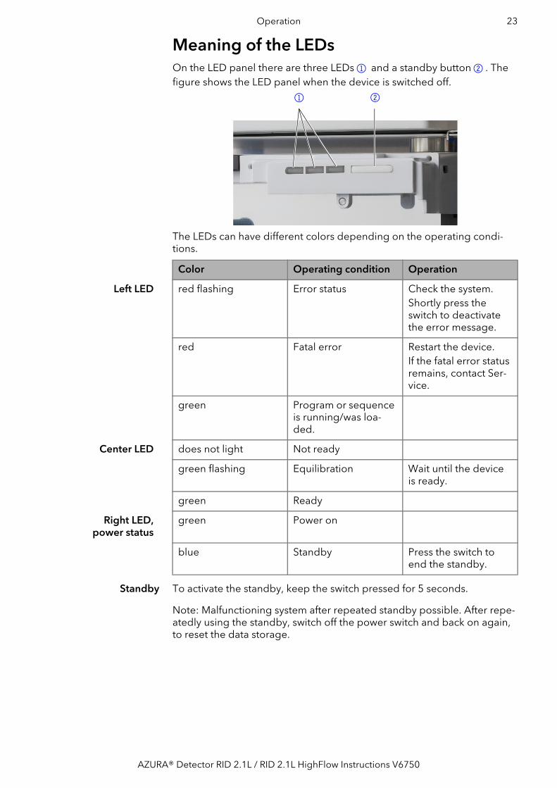
Meaning of the LEDsOn the LED panel there are three LEDs 1 and a standby button 2. The figure shows the LED panel when the device is switched off.
The LEDs can have different colors depending on the operating condi-tions.
Standby To activate the standby, keep the switch pressed for 5 seconds.
Note: Malfunctioning system after repeated standby possible. After repe-atedly using the standby, switch off the power switch and back on again, to reset the data storage.
1 2
Color Operating condition Operation
Left LED red flashing Error status Check the system.Shortly press the switch to deactivate the error message.
red Fatal error Restart the device.If the fatal error status remains, contact Ser-vice.
green Program or sequence is running/was loa-ded.
Center LED does not light Not ready
green flashing Equilibration Wait until the device is ready.
green Ready
Right LED, power status
green Power on
blue Standby Press the switch to end the standby.
AZURA® Detector RID 2.1L / RID 2.1L HighFlow Instructions V6750

24 Operation
Default settingsUsing the Mobile Control, you can reset the detector to its default set-tings.
AutozeroThe autozero command leads to the zeroing of the detector signal. This command can be carried out via software or via analog command.This is a two leveled function: Level one is an electronic or digital zeroing of the signal. Level two is an automatic zero glass adjustment. Level two is carried
out automatically when the baseline drift exceeds a permitted threshold.
The autozero function generates a numeric offset value “a”, employed in the calculation of the detector signal (see “Calculating the signal value” on page 5). By default, an autozero command is automatically carried out at the start of a run.
Parameter Setting
Network settings LAN DHCP Port 10001
Units μRIU
Date/time Current date/time
Data rate 1 Hz
Signal direct
Time constant 2 s
LED power factor 1
temperature 35 °C for AZURA® Detector RID 2.1L
off for AZURA® Detector RID 2.1L HighFlow
Analog output scale 0,5 μRIU/mV for AZURA® Detektor RID 2.1L
5 μRIU/mV for AZURA® Detek-tor RID 2.1L HighFlow
Analog output offset 100 mV
Analog output data rate 20 Hz
Analog output time constant 0.05 s
Leak sensor ON, sensitivity - low
Extended dynamic range OFF
Flushing OFF
Event pulse length 1000 ms
Autozero mode OFF
AZURA® Detector RID 2.1L / RID 2.1L HighFlow Instructions V6750

Operation 25
Temperature controlIt is possible to select the temperature of the optical unit in the range 30–55 °C in 1 °C steps via software. It is recommended to set the temperature 5-10 °C above the ambient conditions, in order to improve and ensure baseline stability.The default values are listed in a separate section (see “Default settings” on page 24).Note: For the AZURA® Detector RID 2.1L HighFlow, the temperature cont-rol is only effective up to a flow rate of 50 ml/min.
Signal modeAccording to the relative refractive indexes of eluent and analyte, it is pos-sible to obtain positive or negative peaks in your chromatogram (also in one run). Positive peaks result when the analyte has a greater refractive index than the eluent. Negative peaks result when analytes have a lower refractive index than the eluent. You can convert the signal of your peaks (direct or inverted) in your chromatogram via the signal mode option in your software.The default values are listed in a separate section (see “Default settings” on page 24).
Time constant & data rateResponse time The time constant influences the response time of the detector. The res-
ponse time determines how quickly the detector responds to a change in signal. A good thumb rule for selection of the time constant is that it should be no larger than the baseline peak width of the first peak of inte-rest (in seconds). Increasing the time constant allows more averaging of the signal (also known as digital filtering) and results in less baseline noise. However, increasing the time constant too much may result in broad peaks, reduced peak heights and asymmetric peak shapes. Therefore, a compromise has to be found.
Time constant Using the time constant a signal smoothing can be achieved. The larger this value is set, the more the signal will be smoothed. In general, the best time constant is the reciprocal of the data rate (see table below). If increa-sed sensitivity is desired, or if the baseline noise is interfering with integra-tion, the time constant should be increased. If resolution is compromised, it should be decreased.It is recommended to set the time constant and data rate in relation to peak width.
Peak width [min] Time constant [s] Datenrate [Hz]
< 0.003 0.01 100
> 0.007 0.02 50
> 0.017 0.05 20
> 0.033 0.1 10
> 0.067 0.2 5
> 0.167 0.5 2
> 0.333 1 1
AZURA® Detector RID 2.1L / RID 2.1L HighFlow Instructions V6750

26 Operation
Data rate The data rate (or sampling rate) is the number of data points per second (Hz) at which the detector transmits data to the computer. The maximum data rate (digital signal) is 100 Hz. Lower data rates store average data points. A 50 Hz data rate averages 2 points. A 10 Hz data rate averages 10 points. The analog data rate is fixed at 20 Hz.The default values are listed in a separate section (see “Default settings” on page 24).
Optimizing the data rate The optimal data rate depends on your application. Too few points across a peak (short data rate) decrease detail and compromise reproducibility. Too many points (high data rate) introduce noise into the system and the resulting files can become very large. Some general considerations are lis-ted below: Each peak should be defined by 20–30 data points. For chromato-
grams with co-eluting peaks or low signal-to-noise ratios, 40–50 data points per peak are recommended.
If all peaks are relatively wide, select a slower data rate. If any peaks of interest is shown less than a few seconds, select a faster
data rate. If the data rate is too slow, the start and end points of the peaks are not
accurately determined. If the data rate is too fast, data files may occupy excessive disk space and post-run analyses may require more proces-sing time.
LED power factorThe LED power factor can be adjusted in order to regulate detector sensi-tivity. Light source life time is also affected by changes to this parameter. By increasing or decreasing this factor, the total linear range of the device is decreased. This setting can be adjusted in your software under Advan-ced Settings.The default values are listed in a separate section (see “Default settings” on page 24).
Sensitivity After changing the LED power factor, the electric current to the light source is altered and consequently the total sum of counts for both diodes is adjusted. By increasing the LED power factor (e.g. from 1 to 1.8), it is possible to increase sensitivity due to decreased signal noise. The upper limit is a total sum of 2 million counts. In the same way, it is possible to decrease the sensitivity by decreasing the LED power factor (e.g. from 1 to 0.5).
LED lifetime By decreasing the LED power factor, the lifetime of the LED light source can be increased.
Extended Dynamic RangeThe option Extended Dynamic Range enables the extension of the dyna-mic measuring range to +100 % (–1000 μRIU offset for AZURA® Detector RID 2.1L and –2500 μRIU offset for AZURA® Detector RID 2.1L HighFlow) or –100 % (+1000 μRIU offset for AZURA® Detector RID 2.1L and +2500 μRIU offset for AZURA® Detector RID 2.1L HighFlow).
If the Extended Danamic Range is deactivated, the positive and negative signals are detected up to +1000 μRIU für den AZURA® Detector RID 2.1L or up to +2500 μRIU for AZURA® Detector RID 2.1L HighFlow (A).
AZURA® Detector RID 2.1L / RID 2.1L HighFlow Instructions V6750

Operation 27
If the positive Extended Measuring Range is activated (+100 %), the zero position is offset to –1000 μRIU for AZURA® Detector RID 2.1L or up to –2500 μRIU for AZURA® Detector RID 2.1L HighFlow, and the measuring range for positive signals is set to +2000 μRIU for AZURA® Detector RID 2.1L or to +5000 μRIU for AZURA® Detector RID 2.1L HighFlow (B). Switching to negative range has the same effect in inverse direction (C).When this option is active, the LED power factor is set to and blocked at 1. In addition, the automatic zero glass adjustment is inactive. The Extended Dynamic Range option can be activated in your software under Advanced Settings.The default values are listed in a separate section (see “Default settings” on page 24).
Analog output scaling and offsetThe software enables to select analog output scaling and offset factors. Scaling factors 0.1 / 0.5 / 1 / 2 / 5 ?RIU/mV are selectable. By reducing the scaling factor, the output signal range is reduced and the sensitivity is also reduced.
Further information on the analog output (see “Connector assignment” on page 20) The default values are listed in a separate section (see “Default settings” on page 24).
GLPThe following GLP data for the detector can be found in your software:
GLP data Units Explanation
Device information Serial number FRAYYWWXXXXX
Firmware version Current device firmware version
Operating time h Running hours since manufacture
Installation date Manufacture date
Last service date
Light source Operating time h Running hours from light source installation
Installation date
Light source number Indicates how often the light source has been changed since manufacture.
Validation data Last measured span μRIU
Last measured span date
AZURA® Detector RID 2.1L / RID 2.1L HighFlow Instructions V6750

28 Operation
Switching on the detectorThe recommended warm-up time for the detector is 60 minutes. This recommendation is applicable after turning the detector on as well as after powering up from standby.
Prerequisite Rear side must be accessible. Detector is switched off.
BurnsHigh concentration of organic solvent vapor may lead to explosion. Check for leaks before starting to work with organic solvents.
Device defectChanges of the environmental temperature cause condensation inside the device. Allow device to acclimate for 3 h, before connecting to power supply
and taking into operation.
Device defectIntruding liquids can cause damage to the device. Place solvent bottles next to the device or in a solvent tray. Moisten the cleaning cloth only slightly.Note: State of safe operation is achieved even after the power connection has been interrupted because of power cut or emergency shutdown.
Result The right and middle LED light up green.
Next steps Flush the flow cell.
Flushing the flow cellFlush the whole system (with opened flush valve) with water for 60 minu-tes minimum before you start the device test.The flush mode activates the magnetic valve to flush the reference cell with eluent. The flow path with active flush mode is described in a sepa-rate section (see “Flow path” on page 5). The flush valve can be activated or deactivated directly via software; alter-natively a flush mode can be configured in the software, so that the flush valve is activated and after a specific time span (30 s, 60 s, 120 s, 400 s) will be deactivated automatically. The flush mode can be cancelled any time with the OFF command. If the flush valve is active, the left LED blinks green. The default values are listed in a separate section (see “Default settings” on page 24).
Prerequisite The detector is supplied with eluent.
Leak sensor Serial number Leak sensor serial number
Firmware version Current leak sensor firmware ver-sion
GLP data Units Explanation
Process Procedure Picture
1. Plug in the power supply cable into the socket2.
2. Push the main switch 1 to ON.1
2
AZURA® Detector RID 2.1L / RID 2.1L HighFlow Instructions V6750

Operation 29
The detector is switched on.
Tools Software or Mobile ControlNote: The flush mode starts via software of Mobile Control. Flush with the eluent which you plan to use for the next measuring. If you change the elu-ent, make sure that the used eluent is mixable with the one used previ-ously. Otherwise flush the flow cell with a solvent which is mixable with both eluents.
Result The detector is now ready to operate.Next steps Start the measuring.
Activating standbyPrerequisite The flow is turned off.
Note: Malfunctioning system after repeated standby possible. After repe-atedly using the standby, switch off the power switch and back on again, to reset the data storage.
Result If you have been successful, the right LED lights blue.
Next steps End the standby by pressing the standby button again.
Switch off the detectorThe detector is designed for the use of different solvents. In case the detector has not been used for several weeks, solvent residues may cause damage. In case you are planning to take the device out of operation for a longer period, fill the capillaries with alcohol (e. g. isopropanol) before switching off.
Prerequisite Rear side must be accessible. Detector is switched on. The flow cell has been flushed (see page 28).
Process Procedure
1. Start the flush mode.2. Check if the LED blinks green.3. After a period of about 30 seconds, stop the flush mode.4. Wait for the end of program.
Process Procedure Picture
1. Press the standby button 2 for about 5 seconds.
2. Wait until the LED 1 lights up blue.
21
Process Procedure Picture
1. Push the main switch 1 to ON.1
AZURA® Detector RID 2.1L / RID 2.1L HighFlow Instructions V6750

30 Functionality tests
Next steps Either bring the device into operation or prepare it for storage (see page 35).
Functionality testsInstallation Qualification
(IQ)The customer may request the Installation Qualification, which is free of charge. In case of a request, the Technical Support of KNAUER or from a provider authorized by KNAUER performs this functionality test during the installation. The Installation Qualification is a standardized document that comes as part of the delivery and includes the following: confirmation of flawless condition at delivery check if the delivery is complete certification on the functionality of the device
Operation Qualification (OQ)
The Operation Qualification includes an extensive functionality test accor-ding to KNAUER standard OQ documents. The Operation Qualification is a standardized document and free of charge. It is not part of the delivery, please contact the Technical Support in case of request. The Operation Qualification includes the following: definition of customer requirements and acceptance terms documentation on device specifications device functionality check at installation site
Test intervals To make sure that the device operates within the specified range, you should test the device regularly. The test intervals are dependent on the usage of the device.
Execution The test can be carried out either by the Technical Support of KNAUER or from a provider authorized by KNAUER (for a fee).Note: Flush the whole system (with opened flush valve) with water for 60 minutes minimum before you start the device test.
TroubleshootingFirst steps: Check all cables. Check all fittings. Check if air has gotten into the supply lines. Check the detector for leaks.
Diagnostics In your software, a number of diagnostic parameters are displayed for monitoring the state of your device. Before beginning a measurement, it is recommended to check these parameters to ensure best results.
Light intensity and balance
The detector signal is determined through the calculation formula (see “signal value” on page 5): Channel 1 (I1) counts measured on diode 1 Channel 2 (I2) counts measured on diode 2Before carrying out a measurement, both diodes must be balanced: this means roughly the same amount of light should fall on both diodes, i.e. Channel 1 and Channel 2 should have roughly the same number of counts.
Zero glass position Ideally before carrying out a measurement, the position of the zero glass should be roughly 0 (Extended Dynamic Range OFF). This ensures a maxi-mum measurement range for both positive and negative peaks. The zero glass position can be recalculated via the Adjust command.
AZURA® Detector RID 2.1L / RID 2.1L HighFlow Instructions V6750

Troubleshooting 31
LED current The actual electrical current from the light source is displayed in % and mA units. This value can be used to monitor the aging of the LED. Howe-ver, this only applies if the same total number of counts is compared over time. The LED current in % value is normalized to LED power factor 1. The LED current in mA is not normalized.
LANGo through the following steps, in case no connection between the com-puter and the devices can be established. Check after each step if the pro-blem is solved. If the problem cannot be located, call the Technical Support.1. Check the status of the LAN connection in the Windows task bar:
Connected
Connection not established
If no connection was established, test the following: Is the router switched on? Is the patch cable connected correctly to the router and the computer?2. Check the router settings: Is the router set to DCHP server? Is the IP address range sufficient for all the connected devices?3. Check all connections: Are the patch cable connected to the LAN ports and not the WAN
port? Are all cable connections between devices and router correct? Are the cables plugged in tightly?4. If the router is integrated into a company network, pull out the patch
cable from the WAN port. Can the devices communicate with the computer, even though the rou-
ter is disconnected from the company network?5. Turn off all devices, router, and computer. First turn on the router and
wait until the self test is finished successfully. Then turn on the devices and PC.
Has this been successful?6. Replace the patch cable to the device with that no connection could be
established. Has this been successful?7. Make sure that the IP port of the device matches the port in the chro-
matography software.
Device problemsThe performance of the detector is largely dependent on the perfor-mance of the HPLC system. Noise can be related to pump stability, the flow cell cleanliness, lamp
quality, mobile phase composition and other factors. Drift is usually related to long-term changes in the environment, such
as detector warm-up or fluctuations in temperature and mobile phase composition.
Further measures Install the maintenance software (service tool). Save device information and send to KNAUER. Inform Technical Support.
AZURA® Detector RID 2.1L / RID 2.1L HighFlow Instructions V6750

32 Troubleshooting
System messagesIf other system messages are displayed besides those listed below, turn the device off and then on. Inform the Technical Support of the manufac-turer in case the system message repeats itself.The system messages are sorted alphabetically.
Message Cause Solution
"Autozero failed. Zero glass adjustment failed”
Autozero not possible due to fai-led zero glass adjustment.
Repeat zero glass adjustment pro-cedure, then try again.
“Device busy” Internal operations have not yet been concluded.
Wait until the detector has com-pleted the process.
”External error” External error, outside the detec-tor.
1. Check the external devices and cable connections.2. Check the system to locate and remove the error.
“Hardware failure” A serious hardware failure has been discovered.
Restart detector. Restart device. If system message persists, contact Technical Support.
“Instrument in standby mode”
Command not allowed during standby mode.
End standby.
“Leak sensor failed” Leak sensor was not found or does not react.
Restart detector.If the leak sensor cannot be found again, contact the Technical Sup-port.
“Leak was detected” A leak was discovered by the leak management system.
1. Switch off detector.2. Find and remove the leak.3. Restart detector.
Not ready. Zero glass adjustment failed”
Operation not possible due to fai-led zero glass adjustment.
Repeat zero glass adjustment pro-cedure, then try again.
“Operation not allowed in current state”
A command has not been comple-ted (e. g. zero glass moving, flush time running, etc.).
Wait until the command has been completed, then try again.
“Optimal light intensity not reached”
Air bubbles in sample or refe-rence cell.
1. Flush detector.
Dirty flow cell or solvents. 2. Clean flow cell and flush with fresh solvents.
Defective LED (likely cause when LED operating hours exceed 20,000 h) or defective flow cell.
3. Restart detector.Restart device. If system message persists, contact Technical Sup-port.
“Preamplifier malfunction. No data acquired”
Defective preamplifier. Restart detector. Restart device. If system message persists, contact Technical Support.
“Temperature control failed”
The upper temperature limit was exceeded caused by a defective heater or mainboard.
Restart detector. Restart device. If system message persists, contact Technical Support.
AZURA® Detector RID 2.1L / RID 2.1L HighFlow Instructions V6750

Maintenance and care 33
Proceeding with tasks after a leakPrerequisite Detector is switched on (see page 29).
Have a cloth for drying at hand.
Next steps Bring the detector into service.
Maintenance and careProper maintenance of your HPLC device will ensure successful analyses and reproducible results. In this chapter, you find the information relevant for maintenance, care and storage. Additionally, you find instructions for maintenance tasks that may be performed by the customer. In case there are any maintenance tasks on that you do not find instructions here, cont-act your supplier or the Technical Support. Note: All wetted components of a device, e. g. flow cells of detectors, have to be flushed with isopropanol first and water second before being maintained, disassembled or disposed.
Maintenance Contract The device may only be opened by the Technical Support of KNAUER or any company authorized by KNAUER. This maintenance work is covered by a separate maintenance contract.
Organic eluents Organic eluents are toxic above a certain concentration. Ensure that work areas are always well-ventilated. When performing maintenance tasks on the detector, always wear safety glasses with side protection, protective gloves, and an overall.
User tasks and intervalsGLP data Using Mobile Control or software, you can read out the operating hours
of the detector. You find a detailed description on how to read out GLP data in the respective instructions.
“Temperature profile failed”
The detector does not reach inter-nal temperature set point, pos-sibly due to defective temperature sensor, mainboard and/or heater.
Restart detector. Restart device. If system message persists, contact Technical Support.
"Zero glass adjustment failed”
Air bubbles in sample or refe-rence cell.
Flush the detector.
“Zero glass drive failure” Defective or blocked motor, loose cable, or dirty or defective light barrier
Restart detector. Restart device. If system message persists, contact Technical Support.
Message Cause Solution
Procedure Picture
1. Remove the leak.2. Using the cloth, dry the leak
tray.3. To acknowledge the error mes-
sage, press the standby button 1.
1
AZURA® Detector RID 2.1L / RID 2.1L HighFlow Instructions V6750

34 Maintenance and care
User tasks Users may perform the following maintenance tasks themselves: Clean the flow cell. Check the calibration (validation). Check the validation value. Regularly check if all fittings are tight (5 Nm for stainless steel fittings,
0.5 Nm for PEEK fittings). All smooth surfaces of the device can be cleaned with a mild, commer-
cially available cleaning solution, or with isopropanol.
Life-threatening injuriesHealth danger if getting in contact with toxic, infectious or radio-active substances. Before disposing of the device or sending it away for repair, you are
required to decontaminate the device in a technically correct manner.
Device defectIntruding liquids can cause damage to the device. Place solvent bottles next to the device or in a solvent tray. Moisten the cleaning cloth only slightly.
Checking calibration/validationPrerequisite Calibration solution has been prepared: 350 mg sucrose is weighed in a
100 ml volumetric flask and filled to the mark with deionized water.Auxiliary material calibration solution
deionized water syringe
Result When the baseline is stable, the measured value is read out. This value should be 512 ?RIU ± 5 %.
Next steps Repeat the process in case the result is not achieved.
Operating hours Measures
20000 Replace LED
Process Procedure
1. Open the flush valve.2. Flush the detector for 5 min with deionized water at 1 ml/min.3. Close the flush valve.4. Continue to flush at the same flow rate until the baseline drift is
below 1 ?RIU/h.
5. Push Autozero.6. Remove the capillary from the IN port.
7. Fill the syringe with the prepared calibration solution.8. Install the syringe on the IN port.9. Slowly and carefully inject the sucrose solution into the detector IN
port.10.Wait until the baseline is stable.
AZURA® Detector RID 2.1L / RID 2.1L HighFlow Instructions V6750

Technical data 35
Preparing the detector for storage or trans-portPay attention that all tubings and capillaries have been emptied or filled with flushing solution (e. g. isopropanol) before storage. To prevent algae formation, do not use pure water.We recommend the same ambient conditions (temperature range and humidity) for storage as during operation (see page 36).
Prerequisite Flow cell has been filled with isopropanol.Detector is switched off.
Tools Open-end wrench
Life-threatening injuriesHealth danger if getting in contact with toxic, infectious or radio-active substances. Before disposing of the device or sending it away for repair, you are
required to decontaminate the device in a technically correct manner.
Next steps If you want to ship the device, reuse the packaging materials that you received with the delivery.
Technical dataMain features
Process Procedure Picture
1. Using the open-end wrench, disconnect the first capillary and close the opening with a hole plug.
2. Using the open-end wrench, disconnect the second capillary and close the opening with a hole plug.
3. Disconnect the power cable from the connector 1 on the rear side.
1
AZURA® Detector RID 2.1L AZURA® Detector RID 2.1L High-Flow
Detector type Analytical refractive index detec-tor
Preparative refractive index detec-tor
Light source Long-life LED
Refractive index range 1.00–1.75 RIU
Noise ± 2.5 nRIU ± 50 nRIU
Drift 200 nRIU/h 2000 nRIU/h
Linearity > 1000 μRIU > 4000 μRIU
Temperature control OFF, 30–55 °C (1 °C steps)
Max. flow rate 10 ml/min (pure water) 100 ml/min (pure water)
Time constants 0.00 / 0.01 / 0.02 / 0.05 / 0.1 / 0.2 / 0.5 / 1.0 / 2.0 / 5.0 / 10,0 s
AZURA® Detector RID 2.1L / RID 2.1L HighFlow Instructions V6750

36 Chemical compatibility of wetted materials
Communication
General
Chemical compatibility of wetted materialsNote: The user is responsible for using fluids and chemicals in an approp-riate and safe way. If there is any doubt, contact the Technical Support of the manufacturer.
Note: The use of tetrahydrofuran (THF) as solvent may lead under certain circumstances to increased noise and greater drift. This can be observed especially when using unstabilized and not devitrified THF, but also when operating a HPLC system in recycling mode. Therefore, when working with THF and a detector, KNAUER recommends the use of stabilized THF and a THF resistant degasser. In addition, we also recommend to avoid the delivery of THF in a cycle (e. g. Recycling-HPLC). If the noise and/or drift is getting worse over a longer period of time, KNAUER recommends to regularly flush the reference cell of the detector with new solvent.
GeneralThe device is very resistant against a variety of commonly used eluents. However, make sure that no eluents or water come in contact with the device or enter into the device. Some organic solvents (such as chlorina-
Autozero Full range
Flow Cell 5 bar back pressure resistance (flow cell included)
Flow cell volume 15 μl 9 μl
Wetted materials Stainless steel/fused silica/PTFE/PEEK
GLP Detailed report about lamp recognition, operating hours, lamp opera-ting hours, number of lamp ignitions.
Maximum data rate 100 Hz (LAN), 20 Hz (analog)
Interfaces 2 x LAN (RJ-45, Dual IP-Stack), USB (Service only), RS-232 (SUB-D 9), pin header, analog (RCA Cinch connector)
Control Front panel, Mobile Control, software, event control, analog, terminal protocol
Inputs Error (IN), Start (IN), Autozero, Flush (IN)
Outputs Event 1, Start (OUT), Error (OUT), +5 V, Valve +24 V
Analog outputs 1 × 0–2.5 V scalable, 20 bit, offset adjustable
Power supply 100–240 V, 50–60 Hz, 65 W
Dimensions 361 × 158 × 523 mm (W × H × D)
Weight 10.8 kg
Leak sensor Yes (internal and external leak management)
Ambient conditions Temperature range: 4-40 °C (39.2-104 °F)humidity: below 90 % (non-condensing)
AZURA® Detector RID 2.1L / RID 2.1L HighFlow Instructions V6750

Chemical compatibility of wetted materials 37
ted hydrocarbons, ether) may cause coating damage or loosen glued components by improper handling. Even small quantities of other subs-tances, such as additives, modifiers, or salts can influence the durability of the materials. Exposure time and concentration have a high impact on the resistance.The following list contains information about the chemical compatibility of all wetted materials which are used in devices made by KNAUER. The data bases on a literature research on the manufacturer specifications of the materials. The wetted materials of the present device are listed in chapter “Technical data”.All resistances listed here refer to an operation at temperatures up to 40 °C, unless stated otherwise. Note that higher temperatures may have a significant impact on the stability of several materials.
PlasticsPolyetheretherketone (PEEK)PEEK is a durable and resistant plastic and, apart from stainless steel, the standard material in HPLC. It can be used at temperatures up to 100 °C and is highly chemical resistant against almost all commonly used solvents in a pH range of 1–12,5. PEEK is potentially moderate resistant against oxi-dizing and reducing solvents.Therefore, following solvents should not be used: Concentrated and oxi-dizing acids (such as nitric acid solution, sulfuric acid), halogenated acids (such as hydrofluoric acid, hydrobromic acid) and gaseous halogens. Hydrochloric acid is approved for most applications.In addition, following solvents can have a swelling effect and may have an impact on the functionality of the built-in components: Methylene chlo-ride, THF and DMSO in any concentration such as acetonitrile in higher concentrations.
Polyethylene terephthalate (PET, outdated PETP)PET is a thermoplastic and semi-crystalline material with high wear resistance. It is resistant against diluted acids, aliphatic and aromatic hydrocarbons, oils, fats and alcohols, but not against halogenated hydrocarbons and ketones. Since PET belongs chemically to esters, it is not compatible with inorganic acids, hot water and alkalis. Maximum ope-rating Temperature: up to 120 °C.
Polyimide (Vespel®)This material is wear-resistant and permanent resilient thermically (up to 200 °C) as well as mechanically. It is chemically broadly inert (pH range 1–10) and is especially resistant against acidic to neutral and organic sol-vents, but vulnerable to pH strong chemical or oxidizing environments: It is incompatible with concentrated mineral acids (such as sulfuric acid), glacial acetic acid, DMSO and THF. In addition, it will be disintegrated by nucleophilic substances like ammonia (such as ammonium salts under alkaline conditions) or acetate.
Ethylene-tetrafluorethylene copolymer (ETFC, Tefzel®) This fluorinated polymer is highly resistant against neutral and alkaline sol-vents. Some chlorinated chemicals in connection with this material should be handled with care. Maximum operating Temperature is 80 °C.
Perfluorethylenpropylene copolymer (FEP), perfluoroalkoxy copo-lymer (PFA) These fluorinated polymers hold similar features as PTFE, but with a lower operation temperature (up to 205 °C). PTA is suitable for ultrapure appli-cations, FEP can be used universally. They are resistant against almost all
AZURA® Detector RID 2.1L / RID 2.1L HighFlow Instructions V6750

38 Chemical compatibility of wetted materials
organic and inorganic chemicals, except elemental fluorine under pres-sure or at high temperatures and fluorine-halogen compounds.
Polyoxymethylene (POM, POM-H-TF) POM is a semi-crystalline, high-molecular thermoplastic material which stands out due to its high stiffness, low friction value and thermic stability. It can even substitute metal in many cases. POM-H-TF is a combination of PTFE fibers and acetal resin and is softer and has better slip properties as POM. The material is resistant against diluted acids (pH > 4) as well as diluted lyes, aliphatic, aromatic and halogenated hydrocarbons, oils and alcohols. It is not compatible with concentrated acids, hydrofluoric acid and oxidizing agent. Maximum operating temperature is 100 °C.
Polyphenylene sulfide (PPS) PPS is a soft polymer which is known for its high break resistance and very high chemical compatibility. It can be used with most organic, pH neutral to pH high, and aqueous solvents at room temperature without concerns. However, it is not recommended for using with chlorinated, oxidizing and reducing solvents, inorganic acids or at higher temperatures. Maximum operating temperature: 50 °C.
Polytetrafluorethylene (PTFE, Teflon®) PTFE is very soft and anti-adhesive. This material is resistant against almost all acids, lyes and solvents, except against fluid natrium and fluoride com-pounds. In addition, it is temperature-resistant from -200 °C to +260 °C.
Systec AF™This amorphous perfluorinated copolymer is inert against all commonly used solvents. However, it is soluble in perfluorinated solvents like Fluori-nert® FC-75 and FC-40, and Fomblin perfluor-polyether solvents from Ausimont. In addition, it is affected by Freon® solvents.
Polychlortrifluorethylene (PCTFE, Kel-F®) The semi-crystalline thermoplastic material is plasticizer-free and dimensi-onally stable, even in a wide temperature range (-240 °C to+205 °C). It is moderately resistant against ether, halogenated solvents and toluene. Halogenated solvents over +60 °C and chlorine gas should not be used.
Fluorinated rubber (FKM) The elastomer consisting of fluorinated hydrocarbon stands out due to a high resistance against mineral oils, synthetic hydraulic fluids, fuels, aro-matics, and many organic solvents and chemicals. However, it is not com-patible with strong alkaline solvents (pH > 13) like ammonia, and acidic solvents (pH value < 1), pyrrole and THF. Operating temperature: Bet-ween -40 °C and +200 °C.
Perfluorinated rubber (FFKM) This perfluoro elastomer has a higher fluorine content as fluorinated rub-ber and is therefore chemically more resistant. It can be employed at hig-her temperatures (up to 275 °C). It is not compatible with Pyrrole.
Non-metalsDiamond-like carbon (DLC) This material stands out due to its high hardness, low friction coefficient and thus minimum wear. In addition, it is highly biocompatible. DLC is inert against all acids, alkalis and solvents commonly used in HPLC.
Ceramic Ceramic is resistant against corrosion and wear and is fully biocompatible. An incompatibility against acids, alkalis and solvents commonly used in HPLC is not known.
AZURA® Detector RID 2.1L / RID 2.1L HighFlow Instructions V6750

Chemical compatibility of wetted materials 39
Aluminium oxide (Al2O3)Due to their high resistance to wear and corrosion, aluminium oxide cera-mics are used as a coating for mechanically stressed surfaces. They are a biocompatible material with low thermal conductivity and low thermal expansion.
Zirconium oxide (ZrO2)Zirconium oxide ceramics are characterized by their high mechanical resistance, which makes them particularly resistant to wear and corrosion. They are also biocompatible, have low thermal conductivity and are resistant to high pressures.
SapphireSynthetic sapphire is virtually pure monocrystalline aluminium oxide. It is biocompatible and very resistant to corrosion and wear. The material is characterized by a high hardness and a high thermal conductivity.
RubySynthetic ruby is monocrystalline aluminium oxide and has a red colora-tion by the addition of some chromium oxide. It is biocompatible and very resistant to corrosion and wear. The material is characterized by a high hardness and a high thermal conductivity.
Mineral woolThis insulating material consists of glass or stone wool fibers and isolates in high oxidizing conditions and at high temperatures. Mineral wool is valid as commonly inert against organic solvents and acids.
Glass, glass fiber, quartz, quartz glassThese mineral materials are resistant against corrosion and wear and are mostly chemical inert. They are compatible with oils, fats and solvents and show a high resistance against acids and lyes up to pH values of 3–9. Con-centrated acids (especially hydrofluoric acid) may embrittle and corrode the minerals. Lyes may ablate the surfaces slowly.
MetalsStainless steel Stainless steel is, apart from PEEK, the standard material in HPLC. Steels with WNr. 1.4404 (316L) are used, or a mixture with higher compatibility. They are inert against almost all solvents. Exceptions are biological appli-cations which are metal ion sensible, and applications with extreme corro-sive conditions. These steels, in comparison to commonly used steels, are increasingly resistant against hydrochloric acid, cyanides and other halo-gen acids, chlorides and chlorinated solvents. The application in ion chromatography is not recommended. In case of electrochemical applications, a passivation must be executed first.
Hastelloy®-CThis nickel-chrome-molybdenum alloy is extremely resistant to corrosion, especially against oxidizing, reducing and mixed solvents, even at high temperatures. This alloy may be used in combination with chlorine, formic acid, acetic acid and saline solutions.
Titanium, titanium alloy (TiA16V4) Titanium has a low weight and a high hardness and stability. Is stands out due to its very high chemical compatibility and biocompatibility. Titan is applied when neither stainless steel nor PEEK are usable.
AZURA® Detector RID 2.1L / RID 2.1L HighFlow Instructions V6750

40 Repeat orders
Repeat ordersThis list for reorders is valid for the time the document has been publis-hed. Deviations afterwards are possible.For reorders of spare parts use the enclosed packing list. Contact the Technical Support in case there are any questions on spare parts or acces-sories.
Further information Further information on spare parts and accessories can be found online: www.knauer.net
Name Order Number
Devices Analytical refractive index detector with flow cell ADD31
Preparative refractive index detector with flow cell ADD33
Accessory kits AZURA® accessory kit FZA02
AZURA® Detector RID 2.1L accessory kit FDD
AZURA® Detector RID 2.1L HighFlow accessory kit FDD38
Documents Instruction V6750
Installation Qualification VIQ_INST
Operation Qualification document VOQ_RID
Leak management Corrugated hose, 16 cm, PE grey A9846-1
Funnel P6431
Exhaust P6432
Capillary guide top P6424
Capillary guide side P6425
Mobile Control Mobile Control license with 10” touchscreen A9607
Mobile Control Chrom license with 10” touch-screen
A9608
Mobile Control license A9610
Mobile Control Chrom license A9612
Tools AZURA® tool kit A1033
Luer-lock glass syringe, 10 ml A0574
AZURA® Detector RID 2.1L / RID 2.1L HighFlow Instructions V6750
Legal information 41
Legal informationTransport damageThe packaging of our devices provides the best possible protection against transport damage. Check the devices for signs of transport damage. In case you notice damages, contact the Technical Support and the forwarder company within three workdays.
Warranty conditionsThe factory warranty for the device is stipulated by contract. During the warranty period, any components with material or design-related defects will be replaced or repaired by the manufacturer free of charge. Please connect to our website for further information on terms and conditions.All warranty claims shall expire in the event that any unauthorized changes are made to the device. This warranty also excludes the following: accidental or willful damage damage or errors caused by third parties that are not contractually rela-
ted to the manufacturer at the time the damage occurs wear parts, fuses, glass parts, columns, light sources, cuvettes and
other optical components damage caused by negligence or improper operation of the device
and damage caused by clogged capillary packaging and transport damageIn the event of device malfunctions, directly contact the manufacturer.KNAUER Wissenschaftliche Geräte GmbHHegauer Weg 3814163 Berlin, GermanyPhone: +49 30 809727-111Telefax: +49 30 8015010e-mail: [email protected]: www.knauer.net
Warranty sealA warranty seal is attached on some devices. The warranty seal is color-coded. A blue seal is used by the assembly or technical support of KNAUER for devices to be sold. After repair, service technicians stick an orange seal in identical position. If unauthorized persons interfere with the device or the seal is damaged, the warranty claim becomes void.
Declaration of conformityThe Declaration of Conformity accompanies the product as a separate document and is available online: http://www.knauer.net/en/knowledge/downloads/declarations-of-conformity.html
AZURA® Detector RID 2.1L / RID 2.1L HighFlow Instructions V6750

42 HPLC glossary
DisposalHand in old devices or disassembled old components at a certified waste
facility, where they will be disposed of properly.AVV marking in Ger-
manyAccording to the German "Abfallverzeichnisverordnung" (AVV) (January, 2001), old devices manufactured by KNAUER are marked as waste electri-cal and electronic equipment: 160214.
WEEE registration KNAUER as a company is registered by the WEEE number DE 34642789 in the German "Elektroaltgeräteregister" (EAR). The number belongs to category 8 and 9, which, among others, comprise laboratory equipment.All distributors and importers are responsible for the disposal of old devices, as defined by the WEEE directive. End-users can send their old devices manufactured by KNAUER back to the distributor, the importer, or the company free of charge, but would be charged for the disposal.
Solvents and other ope-rating materials
All solvents and other operating materials must be collected separately and disposed of properly.All wetted components of a device, e. g. flow cells of detectors or pump heads and pressure sensors for pumps, have to be flushed first with iso-propanol and then with water before being maintained, disassembled or disposed.
HPLC glossaryTerm Definition
Absorption The process of retention in which the solute partitions into a liquid-like coating.
Adsorption A process of retention in which the interactions between the solute and the surface of an adsorbent dominate.
Analytical analysis and determination in terms of volume for HPLC samples (see: preparative).
Response time The time required, after a stepwise change in the composition in the detector cell, for the output signal to reach a predetermined percen-tage (67 %) of the new equilibration value. For example, if the time constant is 1 s, it will take 1 s to attain 67 % the value of the new signal.
Chromatogram Record of a detector signal, depending on output volume of mobile phase and time.
Degasser Degassing module for fluids
Detector device measuring the composition or the quantity of a substance.
GLP Good laboratory practice
Gradient Time-dependent composition of solvent (mobile phase) on low-pres-sure or high-pressure side of system.
Isokratic Mode of sample separation where the composition of a solvent remains constant.
Calibration A process for correcting measuring values by the value that a measu-ring device deviates from the standard.
Capillary Thin metal or PEEK pipe that connects components and devices within the chromatography system.
AZURA® Detector RID 2.1L / RID 2.1L HighFlow Instructions V6750

HPLC glossary 43
Correction factor Factor that arithmetically corrects device-related deviations from mea-suring values.
Solvent Mobile solvent transporting substances to be separated or isolated through the column.
Luer lock Standardized connection system between syringes and cannulaes.
Mobile phase Mobile solvent transporting substances to be separated or isolated through the column.
Packaging material The adsorbent, gel, or solid support used in the chromatography column.
Preparative Isolating the maximum amount of a substance in a short amount of time in a required purity.
Sample Mixture of different components, which are to be separated using chro-matography. They are transported by the mobile phase and dissolved from the column.
Sample loop A loop, which is separated from the system by the valve, that contains sample first. After switching the valve, the eluent flows through the loop and is flushed to the column.
Retention time The time required from an injection of a substance until the maximum concentration of a substance becomes visible.
Backflushing Useful in chromatography to remove compounds that are held strongly at the head of a column.
Column Pipe with final closures, which allow the mobile phase to pass. The pipe contains the packing materials.
Stationary phase The immobile phase involved in the chromatographic process. It is the liquid or the liquid film on the surface of the packing material.
Dead volume Volume of capillaries and system components between mixing cham-ber, injector and column as well as between column and detector.
Carrier material Refers to the support that is used to attach the active ligand, usually by a covalent bond.
Term Definition
AZURA® Detector RID 2.1L / RID 2.1L HighFlow Instructions V6750
44 Index
IndexAabsorption 42accessories 6adsorption 42air draft 9ambient conditions 9analytical 42Autozero 24, 34AVV marking 42AZURA® Neo 3Bbaseline 24, 25, 34Ccalibration 42capillary 42
fitting 12, 13lock ring 12, 13
carrier material 43chromatogram 42column 43contamination 8correction factor 43Ddata rate 3dead volume 43decontamination 8degasser 42detector 42diagnostics 3disposal 8Eearthquake area 9electronic platform
AZURA® Neo 3eluent 25, 28, 29, 33error 23Extended Dynamic Range 3, 26Ffeatures 3flow cell 3, 4, 34, 35, 36
sensitivity 14flow path 5flow rate 35front cover 10GGLP 3gradient 42Iinstallation
site 9IQ 30isocratic 42
Llabel 2, 10LAN
port 17problems 31router 16settings 15setup 16
leak 7leak sensor 11
malfunction 9LED 23Luer lock 43Mmaintenance 33
user 34Mobile Control 3, 22, 29, 33, 40mobile phase 43Nnoise 26, 35Ooperating environment 9OQ 30Ppackaging material 43packing list 6, 10peak 1, 25, 26
width 25port 3port (LAN) 17power supply 7, 10power supply cable 7, 10, 28preparative 43pressure 1, 14, 36refractive index 1, 3, 4, 14, 25, 35repair 8reset 24response time 25, 42retention time 43router (LAN) 16Ssafety equipment 6sample 43sample loop 43scope of delivery 10sensitivity 9, 25, 26, 27serial number 27service interface 2, 3software 3, 11, 15, 22, 24, 25, 27, 28, 33solvent 43
flammability 7line 7
AZURA® Detector RID 2.1L / RID 2.1L HighFlow Instructions V6750

Index 45
self-ignition point 7tray 7
space requirements 9spare parts 6standby 23, 29, 33
malfunction 23stationary phase 43storage 33suitability 1sunlight 9Ttemperature 1, 25
control 3, 9, 25, 35storage 35
test
Installation Qualification 30Operation Qualification 30
torque 12transport damage 41Uuse 1Vventilation 9vibration 9view
front 2Wwarm up time 28warranty 41
warranty seal 41
AZURA® Detector RID 2.1L / RID 2.1L HighFlow Instructions V6750

Latest KNAUER instructions online: www.knauer.net/knowledge
KNAUERWissenschaftliche Geräte GmbHHegauer Weg 3814163 Berlin
Phone:Fax:E-Mail:Internet:
+49 30 809727-0+49 30 [email protected]
© KNAUER 2018