hpgr—faq - synopsis
TRANSCRIPT

Transaction
Paper
Introduction
Contrary to popular belief, high pressuregrinding roll technology is not ‘new’, havingits genesis in the early 20th century as amethod of coal briquetting (Figure 1), andbeing used in comminution applications sincethe mid 1980s. However, while HPGR is nowcommonplace in the briquetting, cement,diamond, and iron ore sectors, its adoption fortrue hard rock comminution duties has beenslow and cautious, and there are still only avery few hard rock operations to haveembraced this rapidly maturing technology.This article endeavours to answer questions onthe subject, provide information, dispel myths,and generally demystify the technology, with aview to encouraging the more widespreadunderstanding of HPGR as an alternative orsupplement to conventional crushing andmilling circuit designs.
The technology
What is HPGR?
The high pressure grinding roll machine
comprises a pair of counter-rotating rollsmounted in a sturdy frame. One roll is fixed inthe frame, while the other is allowed to floaton rails and is positioned using pneumo-hydraulic springs. The feed is introduced to the gap between the rolls and is crushed by the mechanism of interparticle breakage. (Figure 2.)
Comminution performance is largelydetermined by the pressure exerted by thehydraulic system on the floating roll. Typically,operating pressures are in the range of 50–150bar, but can be as high as 180 bar. For thelargest machines, this translates to appliedforces of up to 25 000 kN.
‘Inter-particle breakage’—what’s that?
The mechanism whereby particles are brokenby compression between other particles, asdistinct from single-particle breakage involvingcompression between the surfaces of thecrushing machine.
The manufacturers
Who makes HPGRs?
There are currently three recognized manufac-turers of HPGR machines, namely Polysius (aThyssenKrupp company), KHD (KHDHumboldt Wedag AG), and Köppern(Maschinenfabrik Köppern GmbH & Co KG),all based in Germany.
Are there any differences between themakes?
No fundamental differences; however, thereare some variations in design philosophies. Forexample, Polysius
favour a high aspect ratio design—
HPGR—FAQby C. Morley*
Synopsis
The successful commissioning of the Cerro Verde project in Peru atthe end of 2006 marked the culmination of the efforts of many inthe industry over many years to have high pressure grinding rolltechnology recognized and accepted as a legitimate alternative tothe conventional approach to large-scale hard rock comminutioncircuit design. Other hard-rock projects that have recently adoptedHPGR include Freeport (Indonesia), Boddington (Australia) andAmplats Potgietersrus (South Africa).
With the increasing acceptance of this technology, the need fortechnical presentations and articles exhorting the industry to adapthas diminished somewhat, and it is considered appropriate now toshift the emphasis to the provision of information for thoseconsidering embracing change.
This article endeavours to answer frequently asked questionson the subject of high pressure grinding roll technology, withparticular reference to its application in the hard rock mineralsprocessing sector.
* Fluor Australia Pty Ltd, Perth and presently atAusenco Minerals, Perth Western Australia
© The Southern African Institute of Mining andMetallurgy, 2010. SA ISSN 0038–223X/3.00 +0.00. These papers were selected from the,Comminution ’08 Conference, held in the UK on,17–20 June 2008.
107The Journal of The Southern African Institute of Mining and Metallurgy VOLUME 110 REFEREED PAPER MARCH 2010 ▲

HPGR—FAQ
large roll diameter, smaller width—whereas KHD havetraditionally preferred a low aspect ratio and Köppern a‘square’ ratio. More recently, KHD have offered higher ratiosfor certain large capacity applications.
Polysius and Köppern use self-aligning spherical rollerbearings, whereas KHD use cylindrical roller bearings.
All three manufacturers offer rapid roll change-outdesigns that minimize the turnaround time for replacing wornrolls.
Differences in wear materials are discussed later.
What are the relative merits of the different aspectratios?
The high aspect ratio design is inherently more expensive,but also offers an intrinsically longer wear life for a givenapplication, as the operating gap is larger and the rollsurfaces are exposed to a correspondingly smaller proportionof the material processed. The high aspect ratio design alsoproduces a coarser product due to the greater influence of theedge effect; however, the effect is relatively slight, particularlywith larger units. The low aspect ratio has a higher pressurepeak in the compression zone, and therefore generates a finerproduct. Again, however, the effect is relatively modest.
The ‘edge effect’—what’s that?
The pressure profile across the roll displays a tapering off ofpressure toward the roll edges, leading to impairedcomminution performance. The ‘edge’ proportion is afunction of the operating gap (edge = gap x ~1.2), which is inturn a function of the roll diameter (gap = 2–2.5% ofdiameter), so a high aspect ratio design has a greater edgeeffect.
And the bearing design?
Being fully sealed, the cylindrical roller bearing design allowsthe choice of grease or circulating oil lubrication (although inthe latter case, grease is still required for bearing seallubrication). By contrast, the self-aligning spherical designcan be only grease lubricated to accommodate the relativemovement between shaft and seal.
The nature of the cylindrical bearing design is such that,for large units, multiple bearings are required toaccommodate the machine’s pressing forces, while for thespherical design, single bearing pairs are used.
The users
Who uses HPGR?
The great majority of the 500+ units in operation globally arein the cement sector and are too numerous to identifyindividually. Since their introduction in the mid-1980s,HPGRs have been widely used in the diamond and iron oresectors where they are now considered commonplace. In thehard rock sector (typically copper and gold ores), the firstapplication was a full-scale 15-month trial at Cyprus Sierritain 1995/96.
More recently, HPGR was selected as the preferredtechnology for the Cerro Verde copper/molybdenum project inPeru (commissioned November 2006) and the Boddingtongold/copper project in Western Australia (under constructionat the time of writing). Freeport Indonesia (commissionedNovember 2006) use two units to pretreat ball mill feed, togenerate a finer mill product and consequently enhanceflotation performance.
Amplats Potgietersrus Division (platinum, South Africa)commissioned a single large unit in November 2007. Severalother mining companies in Western Australia areconsidering, or are committed to, using HPGR technology inupcoming projects.
Figure 3 (courtesy of Polysius) illustrates the readyacceptance and rapidly increasing population of HPGRsfollowing their introduction to the diamond and iron oresectors, and also reflects the relatively slow and cautiousapproach in the hard rock sector—although interest here canbe seen to be accelerating, albeit belatedly.
What happened at Cyprus Sierrita? I heard that it wasa failure
While this application is widely considered to have beenunsuccessful as it did not lead to a commercial sale, the factthat the comminution performance of the machine wasimpressive is not in dispute (Thompsen, 1996, Thompsen et al., 1996). The difficulties experienced related to thebehaviour of the wear surfaces, and many valuable lessonswere learnt from this operation about the precautions
▲
108 MARCH 2010 VOLUME 110 REFEREED PAPER The Journal of The Southern African Institute of Mining and Metallurgy
Figure 1—Early briquetting press
Figure 2—HPGR design principle

necessary in circuit design and unit operation for theprotection of the studded roll surfaces and the successfulapplication of HPGR technology (Morley, 2005). Bearing inmind that this was (and was intended to be) a trial, it couldbe argued that it was in fact a success, as the outcome nowforms a large part of the foundation of current machine andcircuit design practice.
The rules
What were the findings from the Cyprus Sierrita trial,and what are the rules for using HPGR in hard rockapplications?
These are discussed in detail elsewhere (Morley, 2005)—themajor issues relate predominantly to protection of the wearsurfaces and can be summarized thus:
➤ Feed must be unsegregated and presented uniformlyacross the roll width
➤ Tramp metal management must be highly efficient andthe system designed so that tramp metal removal doesnot entail stopping of feed to the HPGR
➤ Feed top size should not exceed the operating gapbetween the rolls
➤ For highly competent ores, very high operatingpressures should be avoided
➤ Continuous tyres are preferred to segments asaccelerated wear occurs at the segment boundaries
➤ Roll edge protection and cheek plate design is now welldeveloped and this method of protection is generallypreferred to edge bypass rock-boxes, although thisalternative is still considered in some specializedapplications.
Why so much emphasis on protection of the wearsurfaces?
The machine is mechanically very reliable with availabilityfactors typically in excess of 98%. The great majority of lostoperating time relates to wear surfaces, hence the focus onthis aspect in technology development. The low overallmachine utilization of about 60% during the Cyprus Sierrita
trial was due almost entirely to difficulties and experimen-tation with the roll wear surfaces. Since then, developmentsin wear surface design, and recognition of the foregoing rulesin circuit design and machine protection, have together led toimprovements in overall utilization factors giving today’svalues typically in the range of 92–95%.
Early roll surface designs were borrowed from the cementsector and comprised smooth NiHard and profiled surfacesthat had very limited wear lives when used on hard, abrasiveores. Combined with the time involved in changing outwornrolls, this resulted in very low, often unacceptable machineavailabilities.
The wear life was extended dramatically by theintroduction of studded roll surfaces (which capture crushedmaterial in the interstices to form a so-called autogenouswear layer) and edge wear blocks. Both studs and edgeblocks are of tungsten carbide, which, although hard andwear resistant, is brittle and easily chipped or broken—hencethe need for protective measures.
The change-out time issue was resolved with thedevelopment of rapid roll change-out designs, which reducethe turnaround time from as much as five days to about32–36 hours.
All three manufacturers offer studded roll designs, andthe proprietary Hexadur® surface is available from Köppern.This comprises hexagonal tiles of a proprietary abrasion-resistant material set into a softer matrix, which wearspreferentially in operation allowing the formation of anautogenous wear protection layer at the tile joints. Hexadur’slow profile makes it less susceptible to damage from oversizefeed or tramp metal, and higher operating pressures aretolerable. However, at the time of writing, the population ofHexadur-clad rolls in hard rock applications was small andwear life on abrasive ores unproven. (Figures 4 and 5.)
The terminology
HPGR—FAQTransaction
Paper
109The Journal of The Southern African Institute of Mining and Metallurgy VOLUME 110 REFEREED PAPER MARCH 2010 ▲
Figure 3—HPGR population growth
Figure 4—Studded roll

HPGR—FAQ
There are several unusual terms that seem predomi-nantly to relate only to HPGRs—what do they allmean?
These terms relate to the performance of the HPGR and wereformulated largely to assist in the process of scale-up fromlaboratory or pilot tests to full-scale machines.
➤ Specific press force (N/mm²)—the applied force dividedby the projected area of the roll (width x diameter). Theapplied force does of course increase with machine size,but when normalized in this way becomes independentof size. Typical practical operating values are in therange of 1–4.5 N/mm² for studded roll surfaces and upto 6 N/mm² for Hexadur.
➤ Specific throughput (ts/m³h)—the capacity of amachine with a roll diameter of 1 m, a width of 1 mand a peripheral speed of 1 m/s. It is a function of thefeed material characteristics and roll surface,determined by testwork and used for scale-up. It is alsoknown as specific capacity or ‘m-dot’. Typical valuesfor studded rolls are in the range of 210–260 ts/m³h foran ore SG of 2.7. (Values are proportional to SG.) Fortruncated feeds—i.e. feeds with fines removed—valuesdecrease by about 25%.
➤ Specific gap (% of roll diameter)—determined bytestwork and used in scale-up. Typical values are in therange of 2.0–2.5% for full-fines feed and about1.5–2.0% for truncated feeds.
➤ Specific energy (kWh/t)—the net power draw per unitof throughput. Also independent of machine size, andan almost linear function of specific press force for agiven application. Typical operating values are in therange of 1–3 kWh/t.
➤ Specific power (kW.s/m³)—the product of specificenergy and specific throughput, it is used to estimatethe shaft power required for a given machine.
➤ Shaft power (kW)—the product of specific power andthe diameter, width, and peripheral speed of the rolls.
➤ Unit capacity (t/h)—the product of specific throughputand diameter, width, and peripheral speed of the rolls.
The shaft power and unit capacity predicted by theseformulae can be compared with the measured values of theoperating unit to evaluate the accuracy of scale-up in design.
On the subject of unit capacities, what range isavailable?
Leaving aside the laboratory-size machines, the smallestunits deployed in the field are the KHD and Polysius pilotunits, rated at nominally 20–80 and 80–100 t/h respectively.The largest machine produced to date is the Polysius 24/17(2.4 m diameter, 1.7m wide—in operation at Cerro Verde andordered for the Boddington project). This machine has acapacity of about 2250 t/h and is driven by twin 2500 (CerroVerde) or 2800 kW (Boddington) variable speed motors.
The manufacturers have developed a range of standardsizes between these limits, but are able to engineer machinesof essentially any size. For example, the largest diametermachines to date are the 2.8 m units at Premier diamondmine in South Africa. They are only 0.5 m wide, however,with twin 600 kW drives, so are not particularly large incapacity terms—the large diameter was selected to provide alarge operating gap to avoid diamond breakage. Recently, theroll surfaces were changed from smooth to studded, giving asignificant increase in both capacity and wear life with only aminor impact on size reduction performance.
Operating characteristics
How does HPGR operation vary with feed character-istics?
Ore characteristics having a significant effect on HPGRoperation include competency, abrasiveness, moisture andsize distribution (i.e. full-fines or truncated):
➤ At a given operating pressure, power draw is a functionof ore competency, so that a high-competency ore willgive high power draw and influence bearing and motorselection.
➤ A combination of highly competent ore, high operatingpressures and oversize feed (i.e. top size significantlylarger than the operating gap) is a recipe for studdamage. High pressures and oversize feed are moretolerable with less competent ores.
➤ A high fines or clay content in the feed leads toimpaired comminution efficiencies, although HPGR ismuch better able than cone crushers (for example) totolerate such feeds.
➤ High moisture levels cause reductions in specificcapacity.
➤ Very high moisture levels can cause wash-out of theautogenous layer and lead to accelerated wear.
➤ High ore competency and abrasiveness together lead toincreased wear rates. Note that high abrasiveness alonedoes not necessarily lead to high wear rates—the Bondabrasion index is a poor predictor for HPGR. Themanufacturers have developed standard tests usinglaboratory-size HPGRs for the purpose of predictingwear rates.
▲
110 MARCH 2010 VOLUME 110 REFEREED PAPER The Journal of The Southern African Institute of Mining and Metallurgy
Figure 5—Hexadur
➤ Truncated feeds give reduced specific capacities, acoarser product, and higher wear rates.
➤ Ore type, feed moisture content and operating pressuredetermine flake competency.
‘Flake competency’?
The product of an HPGR is discharged in the form of acompressed cake or flake with a density of about 80 to 85%of the ore SG, depending on operating pressure. Thecompetency of the flake depends primarily on the ore type,with hard, primary ores tending to produce fragile, easilydeagglomerated flakes, and softer, clayey ores (such askimberlites) giving more competent flakes that often needintensive deagglomeration before further treatment.
Control philosophies
How does the operator control the working gapbetween the rolls?
In short, he doesn’t. This and other HPGR myths and miscon-ceptions are discussed elsewhere (Klymowsky, 2003). Theoperating gap is a function primarily of the ore characteristicsand the roll diameter and surface texture, and is only a weakinverse function of operating pressure.
So if the gap can’t be controlled, what can be?
There are only a few variables available to the operator,namely the hydraulic system precharge pressure, theoperating pressure, and the roll speed (assuming a variablespeed drive is fitted).
➤ The precharge pressure determines the stiffness of thepneumo-hydraulic ‘spring’ and the response of themachine to feed irregularities. The optimum setting isore-dependent and determined by test work, andnormally should not need changing after initial set-upduring commissioning.
➤ The operating pressure set-point is adjusted to modifyHPGR performance. Increasing pressure has thefollowing effects:
– Increased specific energy, proportional to thepressure increase
– Slightly reduced capacity due to the smaller gap– Finer product, up to a point—the fineness curve
(say, %-1 mm) approaches a plateau as pressureis progressively increased, whereafter theadditional energy consumed with further increasesin pressure materializes as heat and a higher flakedensity.
➤ Roll speed can be used as an operating variable tocontrol throughput. Capacity increase is not a linearfunction of roll speed as higher speeds result in moreslippage of the ore against the roll surface; however,the effect is only slight with studded rolls due to theinherently high kinetic friction of the autogenous wearlayer.
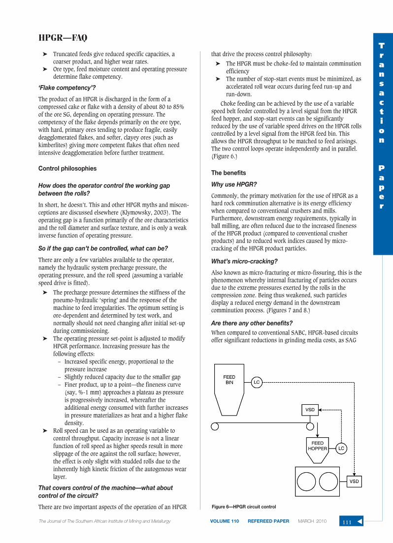
That covers control of the machine—what aboutcontrol of the circuit?
There are two important aspects of the operation of an HPGR
that drive the process control philosophy:
➤ The HPGR must be choke-fed to maintain comminutionefficiency
➤ The number of stop-start events must be minimized, asaccelerated roll wear occurs during feed run-up andrun-down.
Choke feeding can be achieved by the use of a variablespeed belt feeder controlled by a level signal from the HPGRfeed hopper, and stop-start events can be significantlyreduced by the use of variable speed drives on the HPGR rollscontrolled by a level signal from the HPGR feed bin. Thisallows the HPGR throughput to be matched to feed arisings.The two control loops operate independently and in parallel.(Figure 6.)
The benefits
Why use HPGR?
Commonly, the primary motivation for the use of HPGR as ahard rock comminution alternative is its energy efficiencywhen compared to conventional crushers and mills.Furthermore, downstream energy requirements, typically inball milling, are often reduced due to the increased finenessof the HPGR product (compared to conventional crusherproducts) and to reduced work indices caused by micro-cracking of the HPGR product particles.
What’s micro-cracking?
Also known as micro-fracturing or micro-fissuring, this is thephenomenon whereby internal fracturing of particles occursdue to the extreme pressures exerted by the rolls in thecompression zone. Being thus weakened, such particlesdisplay a reduced energy demand in the downstreamcomminution process. (Figures 7 and 8.)
Are there any other benefits?When compared to conventional SABC, HPGR-based circuitsoffer significant reductions in grinding media costs, as SAG
HPGR—FAQTransaction
Paper
The Journal of The Southern African Institute of Mining and Metallurgy VOLUME 110 REFEREED PAPER MARCH 2010 111 ▲
Figure 6—HPGR circuit control

HPGR—FAQ
mill ball consumption is eliminated. While ball mill mediaconsumption is typically slightly higher than in SABC circuitsdue to the coarser transfer size from the HPGR, there is still asubstantial benefit that typically is of the same order ofmagnitude as the savings in energy.
But isn’t this offset by the cost of the replacementHPGR tyres?Studies have shown that, in $/t terms, the cost of HPGR tyresis about the same as that of SAG mill liners. Such studiesgenerally make conservative estimates of HPGR tyre life, andthe longer lives typically achieved in practice tend to enhancethe case for HPGR. This situation has improved further withthe rapid roll removal designs now available from the HPGRmanufacturers, resulting in turnaround times shorter than forthe equivalent SAG mill reline event.
So, there are benefits to be had in energy andgrinding media, with liners about neutral—anythingelse?The literature notes that improvements in downstreamprocessing should be expected due to the reducedovergrinding experienced in HPGR-based circuits, but thebenefits are relatively minor compared to those seen in thecomminution process. However, substantial benefits have
been reported in gold recovery when the HPGR is followed bya heap leach process (Klingmann, 2005).
A further, non-technical benefit lies in the comparativelead times for the supply of SAG mills and HPGRs. Typically,SAG mills, particularly large ones, have considerably longerlead times than HPGRs—differences in the range of six tofourteen months have been estimated for some projects—sothat, if the SAG mill is on the project schedule critical path,HPGR could offer some benefit in project execution time.
HPGR also offers improved plant ramp-up timescompared to SAG-based circuits, as an HPGR can operate atfull throughput almost immediately, and as noted earlier hasa very high mechanical availability factor.
The disadvantages
So much for the benefits—what’s the downside?
At the current stage of development of the HPGR machineand HPGR-based flowsheets, capital costs are generallyhigher than for the equivalent SABC circuit. This is due to theneed to control the HPGR feed top size, implying a closedcircuit secondary crushing step upstream, and to control millfeed top size to avoid milling inefficiencies, implying closedcircuit operation of the HPGR itself. It is the cost of theseclosed circuit facilities—crushers, screens, conveyors, bins,feeders, dust control, tramp metal management—that inflatesthe cost of HPGR-based hard rock comminution circuits.
Therefore, until this capital cost differential can beeliminated or reversed—by further technology innovation inthe design of both machine and circuit—an HPGR-basedcircuit must offer sufficient operating cost benefits to offsetthe additional capital cost over an acceptable payback period.
Application guidelines
How can I tell if HPGR is likely to be attractive for myproject?
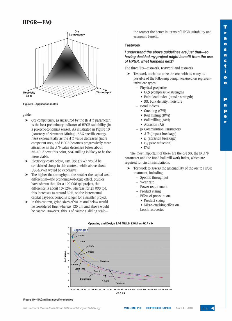
The main drivers influencing the selection of HPGR are orecompetency, electricity cost, and plant throughput. Includedin electricity cost is grinding media cost as the two are linkedwhen media consumption is expressed in g/kWh terms—andas noted earlier, grinding media cost is a significantcomponent in the comparison. Included in plant throughput isproject life, as it is rare for a high throughput to be selectedfor a short project life. A long life allows greater flexibility forthe incremental capital cost payback period to come intoeffect. In Figure 9, if a project’s data point is above thesurface defined by these variables, then HPGR is probablyworth examining as an option; if below, probably not. Afourth factor is fineness of grind—a coarser grind favoursHPGR due to the skewing of comminution energy toward the(more efficient) HPGR.
Can these factors be quantified?
Not precisely, as they are project and ore specific to a degree.It is necessary to conduct the appropriate trade-off studies foreach individual project, as the global database of hard rockHPGR projects is still too small to allow reliablebenchmarking. However, the following can be used as a
▲
112 MARCH 2010 VOLUME 110 REFEREED PAPER The Journal of The Southern African Institute of Mining and Metallurgy
Figure 7—Conventionally crushed particle
Figure 8—HPGR crushed particle
guide:
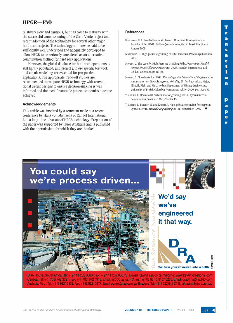
➤ Ore competency, as measured by the JK A*b parameter,is the best preliminary indicator of HPGR suitability (ina project-economics sense). As illustrated in Figure 10(courtesy of Newmont Mining), SAG specific energyrises exponentially as the A*b value decreases (morecompetent ore), and HPGR becomes progressively moreattractive as the A*b value decreases below about35–40. Above this point, SAG milling is likely to be themore viable.
➤ Electricity costs below, say, US3¢/kWh would beconsidered cheap in this context, while above aboutUS8¢/kWh would be expensive.
➤ The higher the throughput, the smaller the capital costdifferential—the economies-of-scale effect. Studieshave shown that, for a 100 000 tpd project, thedifference is about 10–12%, whereas for 25 000 tpd,this increases to around 30%, so the incrementalcapital payback period is longer for a smaller project.
➤ In this context, grind sizes of 90 m and below wouldbe considered fine, whereas 125 μm and above wouldbe coarse. However, this is of course a sliding scale—
the coarser the better in terms of HPGR suitability andeconomic benefit.
Testwork
I understand the above guidelines are just that—sohaving decided my project might benefit from the useof HPGR, what happens next?
The three T’s—testwork, testwork and testwork:
➤ Testwork to characterize the ore, with as many aspossible of the following being measured on represen-tative ore types:
– Physical properties• UCS (compressive strength)• Point load index (tensile strength)• SG, bulk density, moisture
– Bond indices• Crushing (CWi)• Rod milling (RWi)• Ball milling (BWi)• Abrasion (Ai)
– JK Comminution Parameters• A*b (impact breakage)• ta (abrasion breakage)• t10 (size reduction)• DWi
The most important of these are the ore SG, the JK A*bparameter and the Bond ball mill work index, which arerequired for circuit simulations.
➤ Testwork to assess the amenability of the ore to HPGRtreatment, including:
– Specific throughput– Wear rate– Power requirement– Product sizing– Effect of pressure on:
• Product sizing• Micro-cracking effect on:
– Leach recoveries
HPGR—FAQTransaction
Paper
The Journal of The Southern African Institute of Mining and Metallurgy VOLUME 110 REFEREED PAPER MARCH 2010 113 ▲
Figure 9—Application matrix
Figure 10—SAG milling specific energies

HPGR—FAQ
– Milling specific energyFigure 11 (courtesy of Polysius) illustrates that, of the
many ores tested by Polysius, the majority are in the lowabrasive, high fines quadrant, indicating good amenability toHPGR treatment.
➤ Testwork to assess flake competency. This is anessential component of the HPGR test suite, as acompetent flake would indicate the likely need for adedicated deagglomeration step before furthertreatment of the HPGR product. Generally, hardcompetent ores produce a fragile flake that is easilybroken up simply by handling on conveyors and inbins, but it is important to conduct the tests, onrepresentative ore samples, to ensure flowsheet designerrors are avoided. Note that flake competency is not ameasure of an ore’s amenability to HPGR treatment;rather it influences the design of the circuit handlingthe HPGR product.
Circuit modelling and evaluation
I now have my testwork results, which look promising.Can I now proceed with plant design?
In a technical sense, yes—but while technical feasibility hasbeen demonstrated, commercial viability has not yet beenaddressed. For this, it is necessary to:
➤ Conduct simulation modelling of the HPGR-basedcircuit and the alternative—typically SAG-based—todetermine overall comminution specific energyrequirements
➤ Use the model results to size major equipment anddevelop circuit designs to a prefeasibility level of detailfor the two (or more) options
➤ Develop prefeasibility-level capital and operating costsfor each option and conduct life-of-mine financialmodelling to determine to most favourable option.
If the HPGR-based circuit emerges as most favoured, thenboth technical and commercial justification have beenachieved. If a marginal benefit (or penalty) is indicated, it
might be necessary to progress the design and estimate detailto full feasibility level to improve confidence.
Note that fully developed flowsheet concepts are notessential at this stage, provided due cognizance is given tothe HPGR feed and product top-size control requirements andthe possible need for flake deagglomeration as indicated bytestwork.
The primary focus of modelling is to determine overallcomminution specific energy requirements for the variousoptions. For hard rock applications, there is typically asignificant energy saving for HPGR over SABC, but within theHPGR category, little difference between circuit optionsshould be expected.
Flowsheet options
I have now demonstrated that my ore is amenable toHPGR treatment and that the economics of myproject will benefit from the use of this technology. Iam ready to start designing my plant. What are myflowsheet options?
This subject is addressed in detail elsewhere (Morley, 2006)and is too wide ranging to be covered in any depth in anarticle of this nature. Suffice to say that HPGR offers aconsiderable degree of flexibility in its application, but that,for typical hard rock applications, an HPGR-based circuitwould have the general appearance of a three-stage crushingand single stage ball milling circuit, with HPGR used as thethird crushing stage.
In brownfields applications, HPGR can be used todebottleneck conventional crushing/milling circuits andSAB(C) circuits. In the former, HPGR can be used to replaceor supplement conventional (cone) tertiary crushing capacity,or to pretreat ball mill feed to improve milling performance(e.g. Freeport Grasberg). In the latter, HPGR can be used in aprecrushing duty to increase SAG mill feed fineness, or in thepebble crushing circuit (e.g. Empire taconite) to furtherimprove overall AG or SAG mill performance.
Conclusion
Acceptance of HPGR in the hard rock sector has been▲
114 MARCH 2010 VOLUME 110 REFEREED PAPER The Journal of The Southern African Institute of Mining and Metallurgy
Figure 11—Polycom grindability index
relatively slow and cautious, but has come to maturity withthe successful commissioning of the Cerro Verde project andrecent adoption of the technology for several other majorhard rock projects. The technology can now be said to besufficiently well understood and adequately developed toallow HPGR to be seriously considered as an alternativecomminution method for hard rock applications.
However, the global database for hard rock operations isstill lightly populated, and project and ore specific testworkand circuit modelling are essential for prospectiveapplications. The appropriate trade-off studies arerecommended to compare HPGR technology with conven-tional circuit designs to ensure decision-making is wellinformed and the most favourable project-economics outcomeachieved.
Acknowledgements
This article was inspired by a comment made at a recentconference by Hans von Michaelis of Randol InternationalLtd, a long-time advocate of HPGR technology. Preparation ofthe paper was supported by Fluor Australia and is publishedwith their permission, for which they are thanked.
References
KLINGMANN, H.L. Soledad Mountain Project, Flowsheet Development andBenefits of the HPGR, Golden Queen Mining Co Ltd Feasibility Study,August 2005.
KLYMOWSKY, R. High pressure grinding rolls for minerals, Polysius publication,2003.
MORLEY, C. The Case for High Pressure Grinding Rolls, Proceedings RandolInnovative Metallurgy Forum Perth 2005, (Randol International Ltd,Golden, Colorado). pp 15–30.
MORLEY, C. Flowsheets for HPGR, Proceedings 4th International Conference onAutogenous and Semi-Autogenous Grinding Technology, Allan, Major,Flintoff, Klein and Mular (eds.), Department of Mining Engineering,University of British Columbia, Vancouver. vol. iv, 2006. pp. 172–189.
THOMPSEN, L. Operational performance of grinding rolls at Cyprus Sierrita,Comminution Practices 1996, Chapter 15.
THOMPSEN, L, PATZELT, N. and KNECHT, J. High-pressure grinding for copper atCyprus Sierrita, Minerals Engineering 23–26, September 1996. ◆
HPGR—FAQTransaction
Paper
The Journal of The Southern African Institute of Mining and Metallurgy VOLUME 110 REFEREED PAPER MARCH 2010 115 ▲