hpc w thermax opaque wall bod - pace representatives, inc....• astm d1622 – standard test method...
TRANSCRIPT
!
781$541$5060) www.pacerepresentatives.com)Reference'wall'Basis'of'Design'Package.''Registered'design'professional'in'responsible'charge'to'review'prior'to'use.'
Page)1)of)1)Rev:'2016@08@11'
!
Opaque'Envelope'Basis'of'Design'High)Performance)Concrete)Cladding)w/)Thermax)Continuous)Insulation))
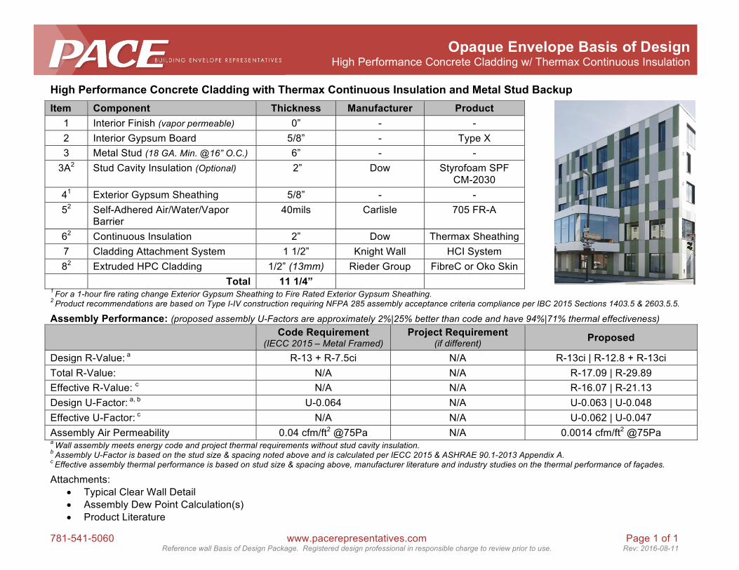
High'Performance'Concrete'Cladding'with'Thermax'Continuous'Insulation'and'Metal'Stud'Backup''
Item' Component' Thickness' Manufacturer' Product'1) Interior)Finish)(vapor'permeable)) 0”) $) $!2) Interior)Gypsum)Board) 5/8”) $) Type)X)3) Metal)Stud)(18'GA.'Min.'@16”'O.C.)) 6”) $) $!3A2) Stud)Cavity)Insulation)(Optional)) )2”) Dow) Styrofoam)SPF)
CM$2030)41) Exterior)Gypsum)Sheathing) 5/8”) $) $)52) Self$Adhered)Air/Water/Vapor)
Barrier)40mils)) Carlisle) 705)FR$A)
62) Continuous)Insulation) 2”) Dow) Thermax)Sheathing)7) Cladding)Attachment)System) 1)1/2”) Knight)Wall) HCI)System)82) Extruded)HPC)Cladding) 1/2”)(13mm)) Rieder)Group) FibreC)or)Oko)Skin)) Total' 11'1/4”' ) )
1'For'a'1@hour'fire'rating'change'Exterior'Gypsum'Sheathing'to'Fire'Rated'Exterior'Gypsum'Sheathing.'2'Product'recommendations'are'based'on'Type'I@IV'construction'requiring'NFPA'285'assembly'acceptance'criteria'compliance'per'IBC'2015'Sections'1403.5'&'2603.5.5.''')
Assembly'Performance:'(proposed'assembly'U@Factors'are'approximately'2%|25%'better'than'code'and'have'94%|71%'thermal'effectiveness)'
) Code'Requirement'(IECC'2015'–'Metal'Framed)'
Project'Requirement'(if'different)' Proposed'
Design)R$Value:)a) R$13)+)R$7.5ci) N/A) R$13ci)|)R$12.8)+)R$13ci)Total)R$Value:) N/A) N/A) R$17.09)|)R$29.89)Effective)R$Value:)c) N/A) N/A) R$16.07)|)R$21.13)Design)U$Factor:)a,)b) U$0.064) N/A! U$0.063)|)U$0.048)Effective)U$Factor:)c) N/A) N/A! U$0.062)|)U$0.047)Assembly)Air)Permeability) 0.04)cfm/ft2)@75Pa) N/A! 0.0014)cfm/ft2)@75Pa)a'Wall'assembly'meets'energy'code'and'project'thermal'requirements'without'stud'cavity'insulation.'''b'Assembly'U@Factor'is'based'on'the'stud'size'&'spacing'noted'above'and'is'calculated'per'IECC'2015'&'ASHRAE'90.1@2013'Appendix'A.'c'Effective'assembly'thermal'performance'is'based'on'stud'size'&'spacing'above,'manufacturer'literature'and'industry'studies'on'the'thermal'performance'of'façades.')
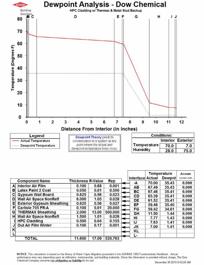
Attachments:)•) Typical)Clear)Wall)Detail)•) Assembly)Dew)Point)Calculation(s))•) Product)Literature)


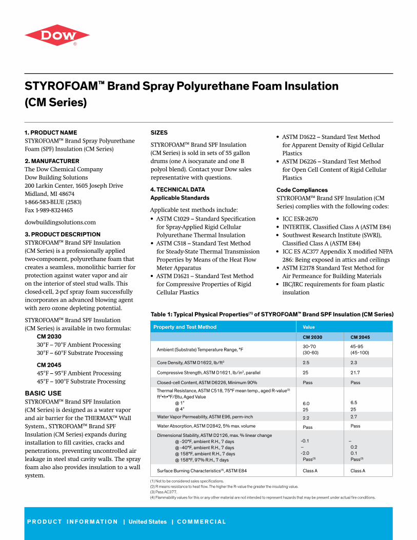
1. PRODUCT NAME STYROFOAM™ Brand Spray Polyurethane Foam (SPF) Insulation (CM Series)
2. MANUFACTURER The Dow Chemical Company Dow Building Solutions 200 Larkin Center, 1605 Joseph Drive Midland, MI 48674 1-866-583-BLUE (2583) Fax 1-989-832-1465
dowbuildingsolutions.com
3. PRODUCT DESCRIPTION STYROFOAM™ Brand SPF Insulation (CM Series) is a professionally applied two-component, polyurethane foam that creates a seamless, monolithic barrier for protection against water vapor and air on the interior of steel stud walls. This closed-cell, 2-pcf spray foam successfully incorporates an advanced blowing agent with zero ozone depleting potential.
STYROFOAM™ Brand SPF Insulation (CM Series) is available in two formulas: CM 2030 30°F – 70°F Ambient Processing 30°F – 60°F Substrate Processing
CM 2045 45°F – 95°F Ambient Processing 45°F – 100°F Substrate Processing
BASIC USE STYROFOAM™ Brand SPF Insulation (CM Series) is designed as a water vapor and air barrier for the THERMAX™ Wall System., STYROFOAM™ Brand SPF Insulation (CM Series) expands during installation to fill cavities, cracks and penetrations, preventing uncontrolled air leakage in steel stud cavity walls. The spray foam also also provides insulation to a wall system.
STYROFOAM™ Brand Spray Polyurethane Foam Insulation (CM Series)
SIZES
STYROFOAM™ Brand SPF Insulation (CM Series) is sold in sets of 55 gallon drums (one A isocyanate and one B polyol blend). Contact your Dow sales representative with questions.
4. TECHNICAL DATA Applicable Standards
Applicable test methods include:• ASTM C1029 – Standard Specification for Spray-Applied Rigid Cellular Polyurethane Thermal Insulation• ASTM C518 – Standard Test Method for Steady-State Thermal Transmission Properties by Means of the Heat Flow Meter Apparatus• ASTM D1621 – Standard Test Method for Compressive Properties of Rigid Cellular Plastics
• ASTM D1622 – Standard Test Method for Apparent Density of Rigid Cellular Plastics• ASTM D6226 – Standard Test Method for Open Cell Content of Rigid Cellular Plastics
Code Compliances STYROFOAM™ Brand SPF Insulation (CM Series) complies with the following codes:
• ICC ESR-2670• INTERTEK, Classified Class A (ASTM E84)• Southwest Research Institute (SWRI), Classified Class A (ASTM E84)• ICC ES AC377 Appendix X modified NFPA 286: Being exposed in attics and ceilings• ASTM E2178 Standard Test Method for Air Permeance for Building Materials• IBC/IRC requirements for foam plastic insulation
(1) Not to be considered sales specifications. (2) R means resistance to heat flow. The higher the R-value the greater the insulating value. (3) Pass AC377.(4) Flammability values for this or any other material are not intended to represent hazards that may be present under actual fire conditions.
Table 1: Typical Physical Properties(1) of STYROFOAM™ Brand SPF Insulation (CM Series)
Property and Test Method Value
CM 2030 CM 2045
Ambient (Substrate) Temperature Range, °F30-70 (30-60)
45-95 (45-100)
Core Density, ASTM D1622, lb/ft3 2.5 2.3
Compressive Strength, ASTM D1621, lb/in2, parallel 25 21.7
Closed-cell Content, ASTM D6226, Minimum 90% Pass Pass
Thermal Resistance, ASTM C518, 75°F mean temp., aged R-value(2)
ft2•h•°F/Btu, Aged Value @ 1” @ 4”
6.0 25
6.5 25
Water Vapor Permeability, ASTM E96, perm-inch 2.2 2.7
Water Absorption, ASTM D2842, 5% max. volume Pass Pass
Dimensional Stability, ASTM D2126, max. % linear change @ -20°F, ambient R.H., 7 days @ -40°F, ambient R.H., 7 days @ 158°F, ambient R.H., 7 days @ 158°F, 97% R.H., 7 days
-0.1 – -2.0
Pass(3)
– 0.2 0.1 Pass(3)
Surface Burning Characteristics(4), ASTM E84 Class A Class A
P R O D U C T I N F O R M A T I O N | United States | C O M M E R C I A L
When used in conjunction withthe THERMAX™ Wall System,STYROFOAM™ Brand SPF Insulation (CM Series)complies with the following codes:
• NFPA 285-[06]: Standard Fire Test Method for Evaluation of Fire Propagation Characteristics of Exterior Non-Load-Bearing Wall Assemblies Containing Combustible Components, Using the Intermediate-Scale, Multistory Test Apparatus• ASTM E331-[00]: Standard Test Method for Water Penetration of Exterior Windows, Skylights, Doors and Curtain Walls by Uniform Static Air Pressure Difference• ASTM E2357-[05]: Standard Test Method for Determining Air Leakage of Air Barrier Assemblies
Contact your Dow sales representative or local authorities for state and local building code requirements and related acceptances.
Physical Properties STYROFOAM™ Brand SPF Insulation (CM Series) exhibits typical physical properties indicated in Table 1 when tested as represented.
Environmental Data STYROFOAM™ Brand SPF Insulation (CM Series) is chloro fluorocarbon (CFC) free and uses the Enovate 3000 blowing agent from Honeywell, which is a zero-ozone depleting product.
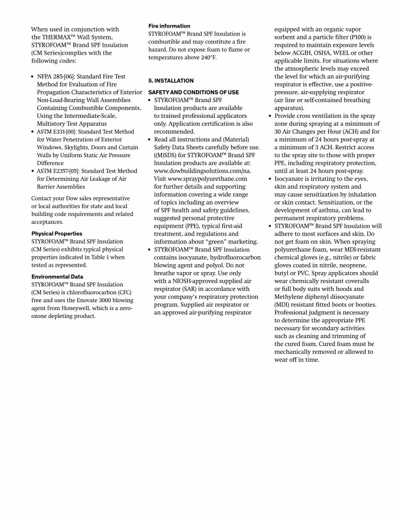
Fire information STYROFOAM™ Brand SPF Insulation is combustible and may constitute a fire hazard. Do not expose foam to flame or temperatures above 240°F.
5. INSTALLATION
SAFETY AND CONDITIONS OF USE • STYROFOAM™ Brand SPF Insulation products are available to trained professional applicators only. Application certification is also recommended. • Read all instructions and (Material) Safety Data Sheets carefully before use. ((M)SDS) for STYROFOAM™ Brand SPF Insulation products are available at: www.dowbuildingsolutions.com/na. Visit www.spraypolyurethane.com for further details and supporting information covering a wide range of topics including an overview of SPF health and safety guidelines, suggested personal protective equipment (PPE), typical first-aid treatment, and regulations and information about “green” marketing.• STYROFOAM™ Brand SPF Insulation contains isocyanate, hydrofluorocarbon blowing agent and polyol. Do not breathe vapor or spray. Use only with a NIOSH-approved supplied air respirator (SAR) in accordance with your company’s respiratory protection program. Supplied air respirator or an approved air-purifying respirator
equipped with an organic vapor sorbent and a particle filter (P100) is required to maintain exposure levels below ACGIH, OSHA, WEEL or other applicable limits. For situations where the atmospheric levels may exceed the level for which an air-purifying respirator is effective, use a positive- pressure, air-supplying respirator (air line or self-contained breathing apparatus).• Provide cross ventilation in the spray zone during spraying at a minimum of 30 Air Changes per Hour (ACH) and for a minimum of 24 hours post-spray at a minimum of 3 ACH. Restrict access to the spray site to those with proper PPE, including respiratory protection, until at least 24 hours post-spray.• Isocyanate is irritating to the eyes, skin and respiratory system and may cause sensitization by inhalation or skin contact. Sensitization, or the development of asthma, can lead to permanent respiratory problems. • STYROFOAM™ Brand SPF Insulation will adhere to most surfaces and skin. Do not get foam on skin. When spraying polyurethane foam, wear MDI-resistant chemical gloves (e.g., nitrile) or fabric gloves coated in nitrile, neoprene, butyl or PVC. Spray applicators should wear chemically resistant coveralls or full body suits with hoods and Methylene diphenyl diisocyanate (MDI) resistant fitted boots or booties. Professional judgment is necessary to determine the appropriate PPE necessary for secondary activities such as cleaning and trimming of the cured foam. Cured foam must be mechanically removed or allowed to wear off in time.

• The contents are under pressure. Ambient and substrate temperatures should be within the range stated in Table 1. Substrate must be at least 5 degrees above dew point, with best processing results when ambient humidity is below 80 percent. Substrate must also be free of moisture (dew or frost), grease, oil, solvents and other materials that would adversely affect the adhesion of the spray polyurethane foam.
Spray equipment must be capable of delivering the proper ratio (1:1 by vol-ume) of polymeric isocyanate and polyol blend at adequate temperatures and spray pressures. Primary and hose heaters should be set between 115°F and 130°F. Dynamic pressures should range between 800 psi and 1200 psi, and should not exceed a difference of 200 psi between the isocyanate and the polyol sides.
It is recommended that STYROFOAM™ Brand SPF Insulation (CM Series) be applied to the stud cavity once all insula-tion board and veneer fasteners have been installed. Apply spray polyurethane
foam in the stud cavity and the inside of the stud flanges to ensure that all fastener penetrations are covered. Apply in consecutive layers of no less than 1/2” and no more than 2”. If mul-tiple layers are used, allow foam to cool completely before applying successive layers.
6. AVAILABILITYSTYROFOAM™ Brand Spray SPF Insula-tion (CM Series) is distributed through an extensive network. For more information, call 1-800-232-2436.
7. WARRANTYSee THERMAX™ Wall System Limited Warranties for details.
8. MAINTENANCESTYROFOAM™ Brand SPF Insulation (CM Series) has a shelf life of six months when stored dry between 60°F and 90°F. Artificial warming of drums is not recom-mended. Caution should be exercised
when opening containers as pressure may be present when material has been exposed to elevated temperatures. Ensure drums are capped after use. Empty drums are nonreturnable and should be disposed of by using current industrial practices in accordance with federal, state or local regulations.
9. TECHNICAL SERVICESDow can provide technical information to help address questions when using STYROFOAM™ Brand SPF Insulation (CM Series). Technical personnel are available to assist with any insulation project. Call 1-866-583-BLUE (2583).
10. FILING SYSTEMS • www.thermaxwallsystem.com • www.dowbuildingsolutions.com
®™Trademark of The Dow Chemical Company (“Dow”) or an affiliated company of Dow. Form No. 179-04063-0615 CDPPrinted in U.S.A.
The Dow Chemical CompanyBuilding Solutions200 Larkin • Midland, MI 48674
NOTICE: No freedom from any infringement of patent owned by Dow or others is to be inferred. Because use conditions and applicable laws may differ from one location to another and may change with time, Customer is responsible for determining whether products and the information in this document are appropriate for Customer’s use and for ensuring that Customer’s workplace and disposal practices are in compliance with applicable laws and other government enactments. The product shown in this literature may not be available for sale and/or available in all geographies where Dow is represented. The claims made may not have been approved for use in all countries or regions. Dow assumes no obligation or liability for the information in this document. References to “Dow” or the “Company” mean the Dow legal entity selling the products to Customer unless otherwise expressly noted. NO EXPRESS WARRANTIES ARE GIVEN EXCEPT FOR ANY APPLICABLE WRITTEN WARRANTIES SPECIFICALLY PROVIDED BY DOW. ALL IMPLIED WARRANTIES INCLUDING THOSE OF MERCHANTABILITY AND FITNESS FOR A PARTICULAR PURPOSE ARE EXPRESSLY EXCLUDED.Dow Polyurethane Foam Insulation and SealantsCAUTION: When cured, these products are combustible and will burn if exposed to open flame or sparks from high-energy sources. Do not expose to temperatures above 240ºF (116ºC). For more information, consult (Material) Safety Data Sheet ((M)SDS) call Dow at 1-866-583-BLUE (2583) or contact your local building inspector. In an emergency, call 1-989-636-4400 in the U.S. or 1-519-339-3711 in Canada. When air sealing buildings, ensure that combustion appliances, such as furnaces, water heaters, wood burning stoves, gas stoves and gas dryers are properly vented to the outside. See website: http://www.epa.gov/iaq/homes/hip-ventilation.html. In Canada visit: http://archive.nrc-cnrc.gc.ca/eng/ibp/irc/bsi/83-house-ventilation.html. STYROFOAM™ Brand Spray Polyurethane Foam contains isocyanate, hydrofluorocarbon blowing agent and polyol. Read all the instructions and (M)SDS carefully before use. Wear protective clothing (including long sleeves), gloves, goggles and proper respiratory protection. Supplied air or an approved air-purifying respirator equipped with an organic vapor sorbent and a P100 particulate filter is required to maintain exposure levels below ACGIH, OSHA, WEEL or other applicable limits. Provide adequate ventilation. Contents under pressure. STYROFOAM™ Brand SPF should be installed by a trained SPF applicator.
Building and/or construction practices unrelated to building materials could greatly affect moisture and the potential for mold formation. No material supplier including Dow can give assurance that mold will not develop in any specific system.
USTechnical Information: 1-866-583-BLUE (2583)Sales Information: 1-800-232-2436
dowbuildingsolutions.com thermaxwallsystem.com
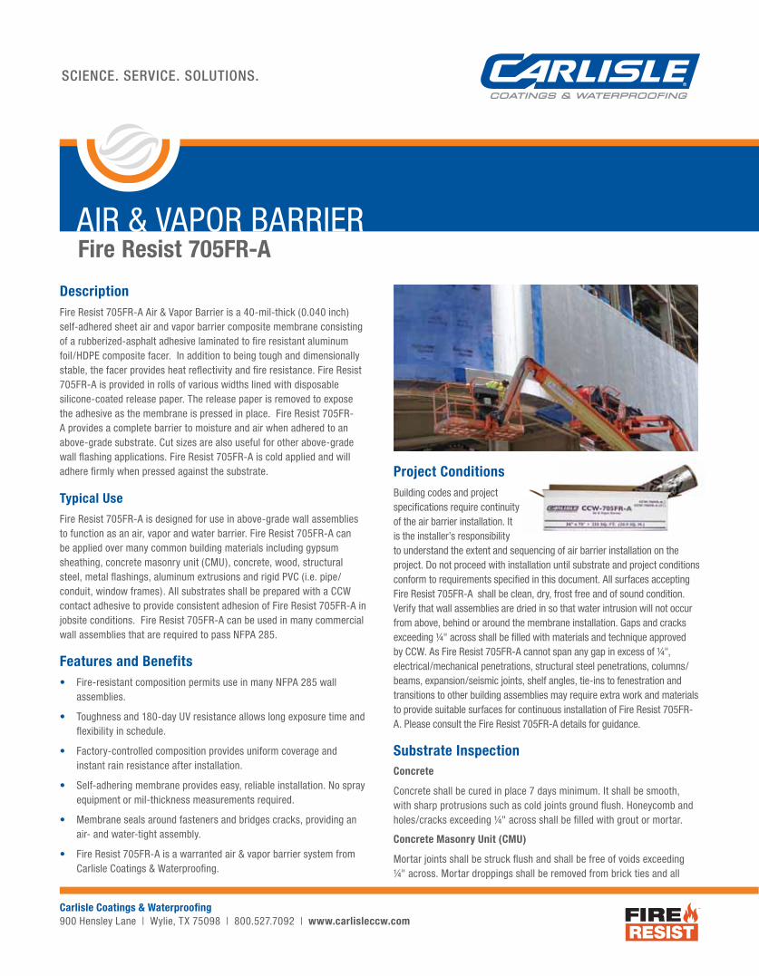
DescriptionFire Resist 705FR-A Air & Vapor Barrier is a 40-mil-thick (0.040 inch) self-adhered sheet air and vapor barrier composite membrane consisting of a rubberized-asphalt adhesive laminated to fi re resistant aluminum foil/HDPE composite facer. In addition to being tough and dimensionally stable, the facer provides heat refl ectivity and fi re resistance. Fire Resist 705FR-A is provided in rolls of various widths lined with disposable silicone-coated release paper. The release paper is removed to expose the adhesive as the membrane is pressed in place. Fire Resist 705FR-A provides a complete barrier to moisture and air when adhered to an above-grade substrate. Cut sizes are also useful for other above-grade wall fl ashing applications. Fire Resist 705FR-A is cold applied and will adhere fi rmly when pressed against the substrate.
Typical UseFire Resist 705FR-A is designed for use in above-grade wall assemblies to function as an air, vapor and water barrier. Fire Resist 705FR-A can be applied over many common building materials including gypsum sheathing, concrete masonry unit (CMU), concrete, wood, structural steel, metal fl ashings, aluminum extrusions and rigid PVC (i.e. pipe/conduit, window frames). All substrates shall be prepared with a CCW contact adhesive to provide consistent adhesion of Fire Resist 705FR-A in jobsite conditions. Fire Resist 705FR-A can be used in many commercial wall assemblies that are required to pass NFPA 285.
Features and Benefits• Fire-resistant composition permits use in many NFPA 285 wall
assemblies.
• Toughness and 180-day UV resistance allows long exposure time and fl exibility in schedule.
• Factory-controlled composition provides uniform coverage and instant rain resistance after installation.
• Self-adhering membrane provides easy, reliable installation. No spray equipment or mil-thickness measurements required.
• Membrane seals around fasteners and bridges cracks, providing an air- and water-tight assembly.
• Fire Resist 705FR-A is a warranted air & vapor barrier system from Carlisle Coatings & Waterproofi ng.
AIR & VAPOR BARRIERFire Resist 705FR-A
SCIENCE. SERVICE. SOLUTIONS.
Carlisle Coatings & Waterproofi ng900 Hensley Lane | Wylie, TX 75098 | 800.527.7092 | www.carlisleccw.com
Project ConditionsBuilding codes and project specifi cations require continuity of the air barrier installation. It is the installer’s responsibility to understand the extent and sequencing of air barrier installation on the project. Do not proceed with installation until substrate and project conditions conform to requirements specifi ed in this document. All surfaces accepting Fire Resist 705FR-A shall be clean, dry, frost free and of sound condition. Verify that wall assemblies are dried in so that water intrusion will not occur from above, behind or around the membrane installation. Gaps and cracks exceeding ¼" across shall be fi lled with materials and technique approved by CCW. As Fire Resist 705FR-A cannot span any gap in excess of ¼", electrical/mechanical penetrations, structural steel penetrations, columns/beams, expansion/seismic joints, shelf angles, tie-ins to fenestration and transitions to other building assemblies may require extra work and materials to provide suitable surfaces for continuous installation of Fire Resist 705FR-A. Please consult the Fire Resist 705FR-A details for guidance.
Substrate InspectionConcrete
Concrete shall be cured in place 7 days minimum. It shall be smooth, with sharp protrusions such as cold joints ground fl ush. Honeycomb and holes/cracks exceeding ¼" across shall be fi lled with grout or mortar.
Concrete Masonry Unit (CMU)
Mortar joints shall be struck fl ush and shall be free of voids exceeding ¼" across. Mortar droppings shall be removed from brick ties and all
SCIENCE. SERVICE. SOLUTIONS.
AIR & VAPOR BARRIERFire Resist 705FR-A
other surfaces accepting Fire Resist 705FR-A and CCW accessories. Allow mortar joints to dry a minimum of 3 days prior to installation of Fire Resist 705FR-A and CCW accessories.
Gypsum Sheathing
Sheathing boards shall be fl ush at joints, with gap between boards according to building code and sheathing manufacturer’s requirements. Sheathing boards shall also be securely fastened to the structure with proper fastener type, technique and spacing according to building code and sheathing manufacturer’s requirements. Sheathing boards shall be repaired or replaced if inspection reveals moisture damage, mechanical damage or if sheathing boards have exceeded the exposure duration or exposure conditions as required by the sheathing manufacturer.
When installing CCW sheet membranes and sheet fl ashings over gyp-sheathing with glass-mat facers, coverage rates for contact adhesives and primers will depend on the porosity and texture of the sheathing and will vary substantially by gypsum-sheathing brand and manufacturer. To achieve consistent contact adhesive and/or primer coverage with adequate tack, it may be necessary to decrease the coverage rate (i.e. Increase the amount applied) of the contact adhesive and/or primer and/or the application of multiple coats. CCW contact adhesives and primers shall be allowed to dry completely (lower temperatures will extend drying time) before additional coats are applied or membranes installed. Caution should be taken as contact adhesives and/or primers applied to gyp-sheathings with glass-mat facers will take longer to dry than other substrates. Multiple adhesion tests should be performed randomly to verify proper application of primer and ensure a successful application.
OSB, Plywood, Lumber, Pressure-Treated Wood
Wood sheathing inspection carries the same protocol given for gypsum sheathing. Also, moisture content, measured with a wood moisture meter in the core of the substrate, shall be below 20%. Do not cover any wooden materials with Fire Resist 705FR-A or CCW accessories if moisture content is 20% or above. Do not encapsulate wood (such as nailers) with membrane, as this will cause premature rot. In most cases fi re- and pressure-treated wood must be kiln dried to accommodate the less than 20% moisture content requirement.
Surface PreparationApply CCW contact adhesive to ALL surfaces accepting Fire Resist 705FR-A. CCW-702, CCW-702 LV, CCW-702 WB, CCW-715, CAV-GRIP™ and TRAVEL-TACK™ are all acceptable for this application. Follow the application instructions on the respective contact adhesive technical data sheet.
InstallationFire Resist CCW-705FR-A is available with either standard or low-temperature adhesive formula. Product label on box will indicate which adhesive is used. Also, product bearing low temperature adhesive has the letters “LT” printed next to the lot number on the facer. Use the LT formula when ambient or substrate temperature is below 40°F. Fire Resist 705FR-A bearing the LT adhesive formula can be used down to 25°F ambient and substrate temperature. Fire Resist 705FR-A with LT adhesive formula becomes diffi cult to handle at installation temperatures above 80°F. Before starting installation, select the better Fire Resist 705FR-A adhesive choice for the project conditions.
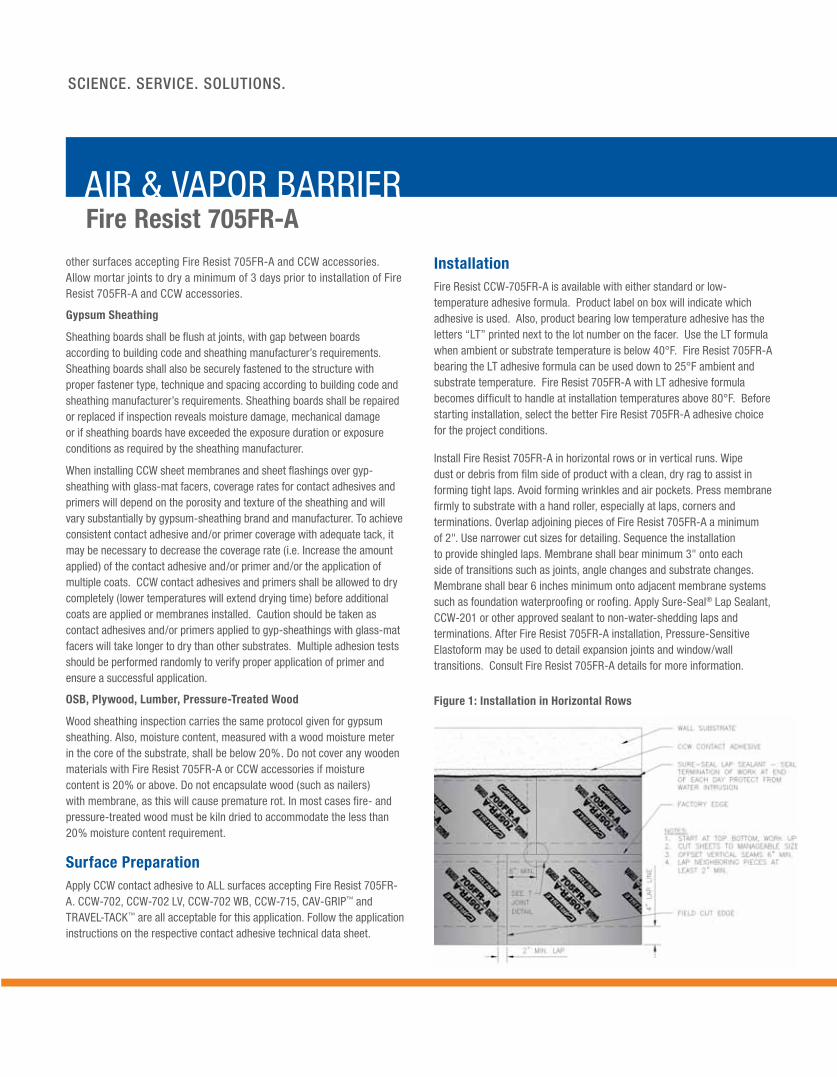
Install Fire Resist 705FR-A in horizontal rows or in vertical runs. Wipe dust or debris from fi lm side of product with a clean, dry rag to assist in forming tight laps. Avoid forming wrinkles and air pockets. Press membrane fi rmly to substrate with a hand roller, especially at laps, corners and terminations. Overlap adjoining pieces of Fire Resist 705FR-A a minimum of 2". Use narrower cut sizes for detailing. Sequence the installation to provide shingled laps. Membrane shall bear minimum 3" onto each side of transitions such as joints, angle changes and substrate changes. Membrane shall bear 6 inches minimum onto adjacent membrane systems such as foundation waterproofi ng or roofi ng. Apply Sure-Seal® Lap Sealant, CCW-201 or other approved sealant to non-water-shedding laps and terminations. After Fire Resist 705FR-A installation, Pressure-Sensitive Elastoform may be used to detail expansion joints and window/wall transitions. Consult Fire Resist 705FR-A details for more information.
Figure 1: Installation in Horizontal Rows

Figure 2: Installation in Vertical Runs
Inspection, Repair And ScheduleProtect membrane from damage by other trades. Do not cover work until it has been inspected according to project requirements. Cover Fire Resist 705FR-A with cladding system as soon as schedule permits. In cold climates, once Fire Resist 705FR-A is installed, avoid heating the building until the exterior insulation is installed. Fire Resist 705FR-A can be left exposed to UV for a maximum of 180 days. Repair damage to membrane by removing loosely adhered material and re-covering with Fire Resist 705FR-A patch, extending beyond the damage by at least 3". Where Fire Resist 705FR-A patch or re-cover is installed, clean debris from surfaces of the old Fire Resist 705FR-A and prepare with CCW contact adhesive. Travel-Tack, a CCW contact adhesive provided in convenient aerosol cans, can be used for this and similar touch-up applications. Seal terminations of repair patch with Sure-Seal Lap Sealant or other approved sealant. If multiple sheets are used in Fire Resist 705FR-A repair/re-cover, offset seams of new installation 12" minimum versus underlying Fire Resist 705FR-A.
Limitations• Do not install over damp, frosty or contaminated surfaces.
• Do not proceed with installation unless ambient and substrate temperatures are 25ºF or above.
• Do not install in areas expected to reach 180°F or higher.
• Fire Resist 705FR-A is a vapor barrier. The design professional shall determine appropriate use in project wall assemblies.
• Do not install over foam insulation as fl ashing tape. Use Aluma-Grip 701 or Foil-Grip 1402 for this application.
• Maximum permitted exposure time of Fire Resist 705FR-A on an un-insulated, vertical wall is 180 days.
• Not intended for traffi c resistance or as a wearing surface.
• Do not install on roofs.
• Do not install over fl exible PVC membrane, silicone, un-cured sealants or other incompatible materials. Consult Fire Resist 705FR-A details for more information.
• Keep edge of membrane ½" minimum back from fi nished exterior.
PackagingFire Resist 705FR-A
36" x 75' roll: (225 ft²/roll) 1 roll/box24" X 100' roll: (200 ft²/ roll) 1 roll/box18" X 100' roll: (150 ft²/ roll) 1 roll/box12" X 100' roll: (100 ft²/ roll) 2 roll/box9" X 100' roll: (75 ft²/ roll), 2 roll/box6" X 100' roll: (50 ft²/ roll) 4 roll/box4" X 100' roll: (33.3 ft²/ roll) 6 roll/box
Fire Resist 705FR-A is available with standard or low temperature (LT) adhesive formulas.
CCW Contact AdhesivesCCW-702 (solvent based, 5-gal pail)CCW-702LV (solvent based, VOC compliant, 5-gal pail)CCW-702WB (water based, 5-gal pail)CCW-715 (solvent based for green concrete, 5-gal pail)CAV-GRIP #40 Aerosol Cylinder
CAV-GRIP gunCAV-GRIP 18' hoseCAV-GRIP 12' hoseCAV-GRIP 6' hoseTRAVEL-TACK (12-oz aerosol cans, 12/carton)
CCW SealantsCCW-201 (2-part Polyurethane, 1.5-gal kit)CCW Universal Single Ply Sealant, 10.1 fl -oz cartidges, 24 per caseSure-Seal Lap Sealant (10.3-fl -oz tubes, 25/carton)
Other Approved SealantsCertain silicone and polyurethane sealants have adequate adhesion to the facer of Fire Resist 705FR-A and are suitable for use over the membrane. A few polyurethane sealants are also chemically compatible with the rubberized-asphalt adhesive. Consult the Fire Resist 705FR-A details for the most current list of approved sealants provided by others.

06.08.15 © 2015 Carlisle.REPRINT CODE: 603998 - Fire Resist CCW-705FR-A Data Sheet
Carlisle, Sure-Seal, TRAVEL-TACK and CAV-GRIP are trademarks of Carlisle.
SCIENCE. SERVICE. SOLUTIONS.
Carlisle Coatings & Waterproofi ng900 Hensley Lane | Wylie, TX 75098 | 800.527.7092 | www.carlisleccw.com
AIR & VAPOR BARRIERFire Resist 705FR-A
Warnings and HazardsWear gloves suitable for cut protection while installing product. The facer of Fire Resist 705 FR-A is highly refl ective. Exposed product on walls can produce glare and can cause signifi cant temperature rise of adjacent landscaping, surfaces or objects. Cover installation as soon as possible if refl ectivity will cause problems.
CCW-702, CCW-702LV and Sure-Seal Lap Sealant contain fl ammable and combustible solvents. Avoid exposure to open fl ame. Avoid breathing vapors. Use only in areas with adequate ventilation. Refer to MSDS for important warnings and product information.
CAV-GRIP, Travel-Tack: USE IN WELL-VENTILATED AREA. Do not puncture or incinerate container. Do not expose to heat or store at temperatures over 120°F. In case of eye contact, fl ush thoroughly with running water for at least 15 minutes and get medical attention. REFER TO PRODUCT DATA SHEET FOR PERFORMANCE CAPABILITIES.
StorageFire Resist 705FR-A rolls should be stored on-end, under cover, and in areas where the temperature is between 40° and 100°F (4.4° and 38°C). Do not double-stack pallets. Shelf life in original, un-opened packaging is 1 year.
Limited WarrantyCarlisle Coatings & Waterproofi ng Incorporated (Carlisle) warrants this product to be free of defects in workmanship and materials only at the time of shipment from our factory. If any Carlisle materials prove to contain manufacturing defects that substantially affect their performance, Carlisle will, at its option, replace the materials or refund its purchase price. This limited warranty is the only warranty extended by Carlisle with respect to its materials. There are no other warranties, including the implied warranties of merchantability and fi tness for a particular purpose. Carlisle specifi cally disclaims liability for any incidental, consequential, or other damages, including but not limited to, loss of profi ts or damages to a structure or its contents, arising under any theory of law whatsoever. The dollar value of Carlisle’s liability and buyer’s remedy under this limited warranty shall not exceed the purchase price of the Carlisle material in question.
Property Method Results
Thickness — 40 mils
Elongation* ASTM D412 300%
Water Vapor Permeance
ASTM E96 A (desiccant method)ASTM E96 B (water method)
0.01 perm0.01 perm
Pliability ASTM D146 Passes @ -25°F0.063" mandrel
Peel Strength ASTM D903 7.5 lb/in width
Tear Initiation and Propagation (Film)
ASTM D4073 32 lbf
Puncture Resistance ASTM E154 80 lbf
Tensile Strength ASTM D882 44 lbf/in
Water Resistance to Hydrostatic Pressure Head
AATCC 127, mod. 22" [55 cm] column of water for 5 hours
No leaking through membrane or 2" bonded lap
Lap Adhesion ASTM D1876 5 lbf/in (average)
Water Absorption ASTM D570 0.12% by wt
Air Permeance ASTM E2178 0.0010 L/s*m² @ 75 Pa
Air Leakage through Assembly
ASTM E2357 0.007 L/s*m² @ 75 Pa [0.0014 CFM/ft² @ 1.57 PSF], max infiltration/exfiltration after load cycling
Installation Temperature
— STD formula: Minimum 40°F, ambient & substrateLT adhesive formula: 25°F ambient & substrate
Service Temperature — -25°F to 180°F
Nail Sealability ASTM D1970 No water leakage
Pull-off Adhesion ASTM D4541, modifi ed 3.75" wood puck, surface prepped with any approved CCW Contact Adhesive
18 PSI (average - on glass mat faced gypsum sheathing)
Burn Performance – Wall Assemblies
NFPA 285 Pass–various exterior wall assemblies with R2+ and other insulations**
Surface Burning ASTM E 84, membrane applied at full coverage to cement board, foil side facing fi re
Flame Spread Index 15, Smoke Generation Index 200
Measurement of Heat Release by Cone Calorimeter
ASTM E 1354, 50 kW/m2 heat fl ux
Peak Heat Release Rate: 6.67 kW/m2 Total Heat Release: 1.1 MJ/m2 Effective Heat of Combustion: -0.57 MJ/kg
* Elongation of rubberized asphalt adhesive ** Ref – CCW Wall Assembly Design Guide
Typical Properties

1. PRODUCT NAMETHERMAX™ Sheathing
2. MANUFACTURERThe Dow Chemical Company Dow Building Solutions 200 Larkin Midland, MI 48674 1-866-583-BLUE (2583) Fax 1-989-832-1465www.dowbuildingsolutions.com
3. PRODUCT DESCRIPTIONTHERMAX™ Sheathing is a non-structural, rigid board insulation consisting of a glass-fiber-infused polyisocyanurate foam core laminated between 1.0 mil smooth, reflective aluminum facers on both sides. The glass-fiber reinforcement contributes to improved fire performance and dimensional stability. THERMAX™ Sheathing can be installed exposed to the interior without a thermal barrier.
THERMAX™ Sheathing offers high, long-term R-value. Used in conjunction with the appropriate joint closure system for the application, THERMAX™ Sheathing with its low perm rating helps to reduce moisture condensation within and behind the insulation.
BASIC USETHERMAX™ Sheathing is specially designed to have a Class A fire rating and can be used in a range of concealed and exposed applications, above and below grade, and can be used in exterior walls. Because of its improved fire performance, THERMAX™ Sheathing is especially appropriate for hourly rated assemblies. THERMAX™ Sheathing is approved for use, per Section 2603.5 of the International Building Code, in Exterior Walls of Types I,II,III and IV construction. THERMAX™ Sheathing is designed for use as
THERMAX™ Sheathing
continuous insulation in both interior and exterior applications to assist in meeting and exceeding both the most current IECC and the ASHRAE 90.1 energy standards. Maximum length is 30 ft. (9.1 m) and maximum thickness is 4.25” (108 mm).
4. TECHNICAL DATA
APPLICABLE STANDARDS THERMAX™ Sheathing meets ASTM C1289 – Standard Specification for Faced Rigid Cellular Polyisocyanurate Thermal Insulation Board, Type I, Class 2. Applicable standards include:
Breaking Load and Flexural Properties of Block-Type Thermal Insulation
Cellulosic Fiber Insulating Board
Steady-State Thermal Transmission Properties by Means of the Heat Flow Meter Apparatus
Compressive Properties of Rigid Cellular Plastics
Response of Rigid Cellular Plastics to Thermal and Humid Aging
Vapor Transmission of Materials
Tensile and Tensile Adhesion Properties of Rigid Cellular Plastics
TYPICAL PHYSICAL PROPERTIESTHERMAX™ Sheathing exhibits the typical physical properties and characteristics indicated in Table 2 when tested as represented.
ENVIRONMENTAL DATATHERMAX™ Sheathing is manufactured with a zero ozone depleting potential. The use of THERMAX™ Sheathing helps reduce the carbon footprint of commercial buildings.
FIRE INFORMATIONTHERMAX™ Sheathing products should be used only in strict accordance with product application instructions. THERMAX™ products are combustible and when used in a building containing combustible materials, may contribute to the spread of fire. For more information, consult MSDS and/or call Dow at 1-866-583-BLUE (2583). In an emergency, call 1-989-636-4400.
CODE COMPLIANCESTHERMAX™ Sheathing complies with the following codes:
Air Permeance of Building Materials - leakage rates less than 0.001 L/s/m2 at a test pressure of 75 Pa.
for Determining Rate of Air Leakage through Exterior Windows, Curtain Walls, and Doors under specified Pressure differences across the specimen. Results were <0.02 L/s/m2
Determining Air Leakage of Air Barrier Assemblies - no leakage
Water Penetration of Exterior Windows, Skylights, Doors, and Curtain Walls by Uniform Static Air Pressure Difference - no leakage
(IRC) Section 316
Section 2603
Metal-Faced – Class 1 Fire Rated to Max. 30’ Exposure High, 4.25” Thick, 4’ Wide, When Installed as Described in the Current Edition of FMRC Approval Guide
Insulated - Steel Deck Roofs™ products are covered
under Underwriters Laboratories Inc. (UL) File R5622
P R O D U C T I N F O R M A T I O N | United States | C O M M E R C I A L

NOTICE: No freedom from infringement of any patent owned by Dow or others is to be inferred. Because use conditions and applicable laws may differ from one location to another and may change with time, Customer is responsible for determining whether products and the information in this document are appropriate for Customer’s use and for ensuring that Customer’s workplace and disposal practices are in compliance with applicable laws and other government enactments. The product shown in this literature may not be available for sale and/or available in all geographies where Dow is represented. The claims made may not have been approved for use in all countries or regions. Dow assumes no obligation or liability for the information in this document. References to “Dow” or the “Company” mean the Dow legal entity selling the products to Customer unless otherwise expressly noted. NO EXPRESS WARR ANTIES ARE GIVEN EXCEPT FOR ANY APPLICABLE WRITTEN WARR ANTIES SPECIFICALLY PROVIDED BY DOW. ALL IMPLIED WARRANTIES INCLUDING THOSE OF MERCHANTABILITY AND FITNESS FOR A PARTICULAR PURPOSE ARE EXPRESSLY EXCLUDED.
CAUTION: This product is combustible and shall only be used as specified by the local building code with respect to flame spread classification and to the use of a suitable thermal barrier. For more information, consult (M)SDS, call Dow at 1-866-583-BLUE (2583) or contact your local building inspector. In an emergency, call 1-989-636-4400.
WARNING: Rigid foam insulation does not constitute a working walkable surface or qualify as a fall protection product.
Building and/or construction practices unrelated to building materials could greatly affect moisture and the potential for mold formation. No material supplier including Dow can give assurance that mold will not develop in any specific system.
®™ Trademark of The Dow Chemical Company (“Dow”) or an affiliated company of Dow. Printed in U.S.A.
Constructions, Roof Deck Construction No. 120 and No. 123
Characteristics of Building Materials
hour wall rated assemblies as listed in the UL Fire Resistance Directory: U026, U326, U330, U354, U355, U424, U425, U460, U902, U904, U905, U906, U907, V454, V482, V499
an Exterior Masonry Wall System Incorporating THERMAX™ Insulation Tested in Accordance With NFPA 285, 2006 Edition (UBC 26.9, intermediate scale – multistory testing)
dowbuildingsolutions.comTechnical Information 1-866-583-BLUE (2583) Sales Information 1-800-232-2436
In the U.S. The Dow Chemical Company Dow Building Solutions200 Larkin Center, Midland, MI 48674
TABLE 1: SIZES, R-VALUES AND EDGE TREATMENTS FOR THERMAX™ SHEATHINGNominal Board Thickness(1), in. R-value (2)(3) Board Size, ft Edge Treatment
0.5 3.3 4 × 8, 4 × 9, 4 × 10 Square Edge
0.75 5 4 × 8, 4 × 9, 4 × 10 Square Edge
1 6.5 4 × 8, 4 × 9, 4 × 10 Square Edge
1.5 9.8 4 × 8, 4 × 9, 4 × 10 Square Edge, Shiplap
2 13 4 × 8, 4 × 9, 4 × 10 Square Edge, Shiplap
(1) Vertical compressive strength is measured at 10 percent deformation or at yield, whichever occurs first.
Interior Materials – Passenger Cars, Multipurpose Passenger Vehicles, Trucks and Buses (Docket No. 3-3; Notice 4)
Insulation on CMU Block
Contact your Dow sales representative or local authorities for state and local building code requirements and related acceptances.
5. INSTALLATION
Boards of THERMAX™ Sheathing are lightweight and can be sawed or cut with a knife. They install quickly to walls (girts, steel stud, tilt-up, block, wood) and
ceilings – inside and outside of purlins, trusses or bar joints. Butt joints must be installed over structural members. “Best practice” recommendations for high-humidity environments include continuously sealing the surface of the insulation at all joints with a Dow joint closure system.
Contact a local Dow representative or access the literature library at www.dowbuildingsolutions.com for more specific instructions.
6. AVAILABILITYTHERMAX™ Sheathing is manufactured in several locations and is distributed through an extensive network. For more information, call 1-800-232-2436.
7. WARRANTYFifteen-year limited warranty is available. Contact your Dow representative for details.
8. MAINTENANCENot applicable.
9. TECHNICAL SERVICESDow can provide technical information to help address questions when using THERMAX™ Sheathing. Technical personnel are available to assist with any insulation project. For technical assistance, call 1-866-586-BLUE (2583).
10. FILING SYSTEMS
Form No. 179-04015 -0715 CDP
(1) Contact your Dow seller for information at different R-values and other sizes and lead time requirements. Not all product sizes are available in all regions.
(2) R means resistance to heat flow. The higher the R-value, the greater the insulating power. Stabilized R-values @ 75°F mean temperature determined in accordance with ASTM C518. R-values expressed in ft2
Property and Test Method Value
Compressive Strength (1), ASTM D1621, psi, min. 25
Flexural Strength, ASTM C203, psi, min. 40
Water Absorption, ASTM C209, % by volume, max. 0.1
Water Vapor Permeance, ASTM E96, perm, max. ≤0.04
Maximum Use Temperature, °F 250
TABLE 2: TYPICAL PHYSICAL PROPERTIES OF THERMAX™ SHEATHING
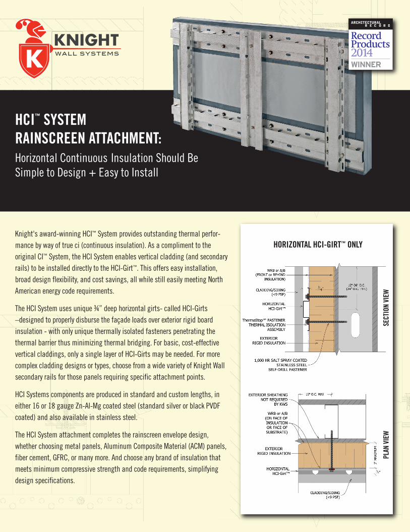
HCI™ SYSTEM RAINSCREEN ATTACHMENT: Horizontal Continuous Insulation Should Be Simple to Design + Easy to Install
Knight's award-winning HCI™ System provides outstanding thermal perfor-mance by way of true ci (continuous insulation). As a compliment to the original CI™ System, the HCI System enables vertical cladding (and secondary rails) to be installed directly to the HCI-Girt™. This offers easy installation, broad design flexibility, and cost savings, all while still easily meeting North American energy code requirements.
The HCI System uses unique ¾” deep horizontal girts- called HCI-Girts –designed to properly disburse the façade loads over exterior rigid board insulation - with only unique thermally isolated fasteners penetrating the thermal barrier thus minimizing thermal bridging. For basic, cost-effective vertical claddings, only a single layer of HCI-Girts may be needed. For more complex cladding designs or types, choose from a wide variety of Knight Wall secondary rails for those panels requiring specific attachment points.
HCI Systems components are produced in standard and custom lengths, in either 16 or 18 gauge Zn-Al-Mg coated steel (standard silver or black PVDF coated) and also available in stainless steel.
The HCI System attachment completes the rainscreen envelope design, whether choosing metal panels, Aluminum Composite Material (ACM) panels, fiber cement, GFRC, or many more. And choose any brand of insulation that meets minimum compressive strength and code requirements, simplifying design specifications.
HORIZONTAL HCI-GIRT™ ONLY
PLAN
VIE
WSE
CTIO
N VI
EW

28308 N Cedar Road, Deer Park, WA 99006www.knightwallsystems.com1-855-597-9255 (KWS-WALL)509.262.0104
HCI, HCI-Girt, ThermaStop, PanelRail and RevealRail are trademarks of Knight Wall Systems, Inc. Patent 8,429,866 B2 and others pending.
¤ Energy & Atmosphere (EA) Prequisite and Credit 1¤ Materials & Resources (MR) Credits 4 and 5
ALL KNIGHT WALL SYSTEMS COMPONENTS ARE MANUFACTURED IN THE USA.
NO EXPRESS WARRANTIES ARE GIVEN EXCEPT FOR ANY APPLICABLE WRITTEN WARRANTIES SPECIFICALLY PROVIDED BY KNIGHT WALL SYSTEMS. ALL IMPLIED WARRANTIES INCLUDING THOSE OF MERCHANTABILITY AND FITNESS FOR A PARTICULAR PURPOSE ARE EXPRESSLY EXCLUDED. No freedom from any patent owned by Knight Wall Systems or others is to be inferred. Because use conditions and applicable laws may differ from one location to another and may change with time, Customer is responsible for determining whether products and the information in this document are appropriate for Customer’s use.
KNIGHT WALL CAN CONTRIBUTE TO THEFOLLOWING USGBC LEED CREDITS:
ADVANTAGES TO THE KNIGHT HCI™ SYSTEM RAINSCREEN
• Horizontal HCI-Girts can be spaced from 12” up to 36” O.C.*
• Support cladding weighing up to 9 PSF*, covering many popular cladding types
• Real labor savings – no notching or cutting of exterior rigid board insulation like with Z girts, brackets or clips
• Thermally isolated fasteners with specially designed ThermaStop™
washers come preassembled
• Highly corrosive-resistant Zn-Al-Mg ZM40 (ASTM A1046) coated steel provides a long service life vs. typical G90 Galvanized steel
• Black PVDF finish or stainless steel options available, competitively priced
• Easily installed over any type of substrate – steel studs, wood studs, CMU, concrete, even brick
• Engineering calculations provide design load compliance for each specific project
• Attach nearly any type of cladding – supplied by any manufacturer – with easy and efficient detailing and installation
• Use any manufacturers insulation meeting minimum compressive strength and other code requirements
• Cladding can be attached directly to the horizontal HCI-Girt or used with optional vertical rails (such as PanelRails or RevealRails)
• Excellent ventilation with a ¾-inch minimum continuous rainscreen cavity
• Pre-engineered and 3rd party tested for proven performance and durability
• Competitive, budget conscious assembly that meets ASHRAE 90.1 standard
• Complete, drop-in rainscreen attachment system – girts, thermally isolated fasteners, rails and engineering – one source liability for the whole system
• Limited labor and material warranty
*Maximum allowable spacing and dead load (weight of cladding) is based on the total load (dead + live) acting on the assembly and connections. Wall anchors must be specified and supplied by KWS for a written limited warranty. Knight will specify the exact anchor type, embedment depth and spacing for anchors in project specific engineering packages. ThermaStop thermal isolation washers must be used on all types of wall anchors with the HCI or CI System, no matter the substrate. Contact KWS for more information.
HCI-GIRT™ + REVEALRAIL™
PLAN
VIE
WSE
CTIO
N VI
EW
Beton lebt.
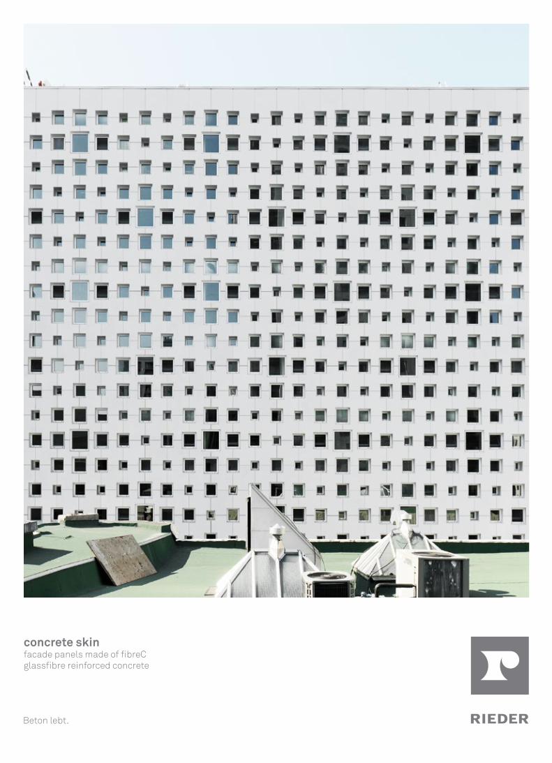
concrete skin facade panels made of fibreC glassfibre reinforced concrete

concrete skin
The development of concrete skin was inspired by Rieder‘s vision of a concrete cladding panel that is both stable and lightweight. The large-format panels are 13 mm thin and give architects plenty of scope in the design of individual facades, with regard to color, structure and form. Glassfibre reinforced concrete is non-combustible and made of mineral-based raw materials, giving the panels their unique characteristics. The authentic appearance creates a vivid facade. Since concrete skin can be used for interior applications, it becomes possible to overcome traditional boundaries of space and to increase the element of flow inherent in the materials. Interior and exterior spaces are merged into one.
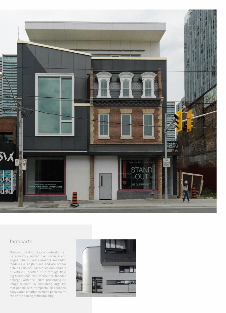
Thanks to its ductility, concrete skin can be smoothly guided over corners and edges. The curved elements are tailor-made as a single piece and are obtain-able as semicircular arches and corners or with a U-section. It is through flow-ing transitions that monolithic facades emerge, with the joints presenting an image of calm. By combining large-for-mat panels with formparts, an economi-cally viable solution is made possible for the entire casing of the building.
formparts

Please note Subject to misprints and typesetting errors. Due to technical reasons printed colors may differ from the original shade. For exact color specification and matching, original concrete skin color samples must be used. Concrete is a natural material. The raw materials used for the production create a specific surface appearance which is typical for concrete. This play of colors within a certain color shade is intentional and enhances the vivid character of concrete. For further details regarding planning and execution, please consult our „technical manual“ or www.rieder.cc. Fotos Ditz Fejer CA/US 06/2016
Rieder Smart Elements GmbH Mühlenweg 22 | 5751 Maishofen | Austria+43 6542 690 844 [email protected] | www.rieder.cc
terr
asa
ndst
one
saha
raliq
uide
bla
ckan
thra
cite
chro
me
silv
ergr
eyiv
ory
off-
whi
tepo
lar w
hite
terr
acot
tagr
een
ferro ferro light matt
Sizes1200 x 2500 x 13 mm (CA)1200 x 3100 x 13 mm (CA)1200 x 3600 x 13 mm (CA)
Fastening systemsSubstructure: aluminum, steelVisible: rivets, screwsConcealed: undercut anchor, adhesive, Rieder Power Anchor (coming soon)
Product characteristicsBuilding material class A1 (according to DIN 4102), non-combustibleDead load / mass per unit area 26 - 31.5 kg/m² | 5.33 - 6.45 lbs/ft²Bending tensile strength > 18 N/mm²
Colors and surfaces12 colors, through-colored 3 surfaces: ferro (sandblasted), ferro light (finely sandblasted) and matt (brushed)
More colors and sizes are available on request.
Technical data
concrete skin for interior design
DistributorfibreC North America by Sound Solutions Inc.1-877-740-0303 (toll free)[email protected] | [email protected] | www.rieder.cc
47 5/8” x 8’-2 27/64” x 1/2“ (US)47 5/8” x 10’-2” x 1/2“ (US)47 5/8” x 11’-9 ¾” x 1/2“ (US)
COVER
Hotel Mount Stephen, Montreal | lemay architects ivory, matt, concealed fastened
PAGE 2
University of Ottawa, Vanier hall | Diamond Schmitt architects terra, matt & ferro light, face fastened
Private residence, Chicago | DMAC architecture polar white, ferro light, concealed fastened
Sheridan College, Oakville | Rounthwaite Dick & Hadley sandstone, matt & ferro light, concealed fastened
PAGE 3
365 Queen Street, Toronto | Montgomery Sisam architects liquide black, matt & ferro, concealed fastened
polar white, matt, face fastened
Residential building, Austria | Seelos architects sahara, ferro & ferro light, concealed fastened
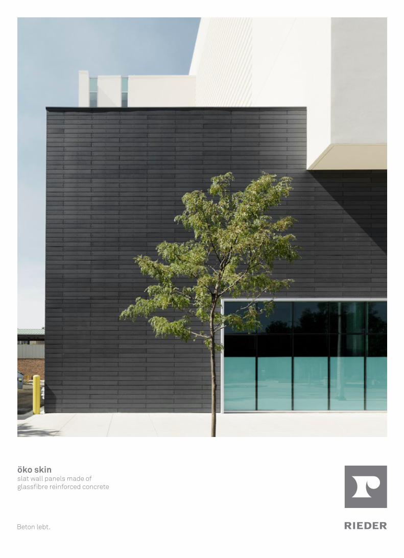
öko skinslat wall panels made of glassfibre reinforced concrete
Beton lebt.
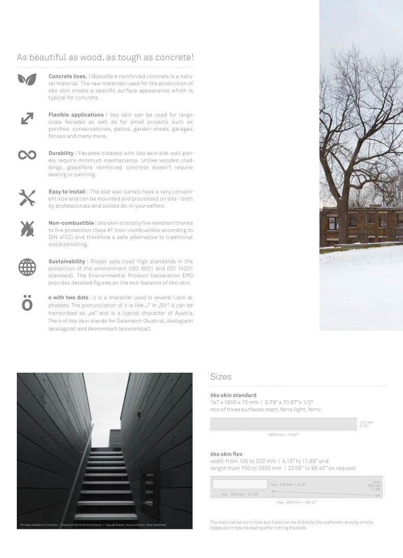
As beautiful as wood, as tough as concrete!
Concrete lives. | Glassfibre reinforced concrete is a natu-ral material. The raw materials used for the production of öko skin create a specific surface appearance which is typical for concrete.
Flexible applications | öko skin can be used for large-scale facades as well as for small projects such as porches, conservatories, patios, garden sheds, garages, fences and many more.
Durability | Facades cladded with öko skin slat wall pan-els require minimum maintenance. Unlike wooden clad-dings, glassfibre reinforced concrete doesn‘t require sealing or painting.
Easy to install | The slat wall panels have a very conveni-ent size and can be mounted and processed on site - both by professionals and skilled do-it-yourselfers.
Non-combustible | öko skin is totally fire resistant thanks to fire protection class A1 (non-combustible according to DIN 4102) and therefore a safe alternative to traditional wood panelling.
Sustainability | Rieder sets itself high standards in the protection of the environment (ISO 9001 and ISO 14001 standard). The Environmental Product Declaration EPD provides detailed figures on the eco-balance of öko skin.
o with two dots | ö is a character used in several Latin al-phabets. The pronunciation of ö is like „i“ in „Sir“. ö can be transcribed as „oe“ and is a typical character of Austria. The ö of öko skin stands for Österreich (Austria), ökologisch (ecological) and ökonomisch (economical).
öko skin standard147 x 1800 x 13 mm | 5.79” x 70.87”x 1/2“ mix of three surfaces matt, ferro light, ferro
Sizes
öko skin flexwidth from 105 to 302 mm | 4.13” to 11.89” andlength from 700 to 2500 mm | 27.56” to 98.42” on request
1800 mm | 70.87”
147 mm5.79”
min. 700 mm | 27.56”
min. 105 mm | 4.13”
max. 2500 mm | 98.42”
max.302 mm
11.89”
The slats can be cut to size and holes can be drilled by the craftsmen directly on site. Edges don‘t require sealing after cutting the slats.
Private residence Toronto | Diamond Schmitt Architects | liquide black, two surfaces, face fastened

Colors and surfaces
öko skin is through-colored including iron oxide and natural additives. The authentic colors of öko skin fit well in landscapes and blend with nature and the environment. Each palette includes three textures
ferro, ferro light and matt which create a naturally varied and vivid surface. The play of colors within a certain color shade is intentional and enhances the character of concrete.
terrasandstonesaharaliquide blackanthracitechrome silvergreyivoryoff-whitepolar white terracotta green
ferr
ofe
rro
light
mat
t
St Denis Junior Public School, Toronto | Bortolotto Architects | off-white, two surfaces, face fastened

1
2
43
5
6
Rieder Smart Elements GmbH Mühlenweg 22 | 5751 Maishofen | Austria+43 6542 690 844 [email protected] | www.rieder.cc
Distributorfi breC North America by Sound Solutions Inc.1-877-740-0303 (toll free)[email protected] | [email protected] | www.rieder.cc
Please note For details on colors and surfaces please refer to “öko skin characteristics“ on www.rieder.cc. Subject to misprints and typesetting errors. Due to technical reasons printed colors may differ from the original shade. For exact color specifi cation and matching, original öko skin color samples must be used. Cover Joliet Junior College | Demonica Kemper Architects | liquide black, two surfaces, face fastened Photos Ditz Fejer, A-Frame, OFIS architects CA/US 06/2016
öko skin slat wall panels are used as facade cladding and mounted on a substructure. They can be installed both horizontally and vertically. öko skin slats can be fastened with screws, rivets or adhesive to an alu-minium substructure. Screws and rivets are available in color matched fi nish. öko skin fl ex 302 mm | 11.89” can be also installed as lap siding.
Installation Layout examples
NEW | Concealed fastening with RPA Rieder Power Anchor
1 insulation2 horizontal subgirt support3 screw4 hat channel subgirt5 öko skin slat6 open vertical joint
Assembly principle: screws on aluminium substructure
For further details on processing and mounting please consult our "installation instruc-tions" on www.rieder.cc (refer to country-specifi c regulations).
öko skin 147 mm, anthracite, vertical installation (1/3 shifted), screwed on aluminium substructure
öko skin fl ex 125 mm, terra,horizontal instal-lation (1/2 shifted), screwed on wooden substructure
öko skin fl ex 147 mm,silvergrey, vertical installation, screwed on wooden substructure
Coming soon!öko skin 147 mm,anthracite vintage, horizontal installation (1/2 shifted), glued on aluminum substructure