hp virtual connect for c-class bladesystem version 3.01 ...h20628. · hp virtual connect for...
TRANSCRIPT

HP Virtual Connect for c-Class BladeSystem Version 3.01 User Guide
Part Number 621011-001 June 2010 (First Edition)

© Copyright 2010 Hewlett-Packard Development Company, L.P.
The information contained herein is subject to change without notice. The only warranties for HP products and services are set forth in the express warranty statements accompanying such products and services. Nothing herein should be construed as constituting an additional warranty. HP shall not be liable for technical or editorial errors or omissions contained herein.
Microsoft is a U.S. registered trademark of Microsoft Corporation.
Intended audience
This document is for the person who installs, administers, and troubleshoots servers and storage systems. HP assumes you are qualified in the servicing of computer equipment and trained in recognizing hazards in products with hazardous energy levels.
Contents
Introduction .................................................................................................................................. 6 Virtual Connect documentation ...................................................................................................................... 6
Overview ..................................................................................................................................... 7 Virtual Connect overview .............................................................................................................................. 7
Using multiple enclosures .................................................................................................................... 8
HP Virtual Connect Manager.......................................................................................................... 9 Configuring browser support ......................................................................................................................... 9 Virtual Connect and RDP ............................................................................................................................... 9 Accessing HP Virtual Connect Manager ....................................................................................................... 10
Command line overview ................................................................................................................... 11 Logging on to the HP Virtual Connect Manager GUI ...................................................................................... 11 HP Virtual Connect Home ............................................................................................................................ 12 About HP Virtual Connect Manager ............................................................................................................. 12 Navigating the HP Virtual Connect Manager GUI .......................................................................................... 13
Navigation overview ........................................................................................................................ 13 Tree view ........................................................................................................................................ 14 Domain Status summary .................................................................................................................... 15 Domain Status screen ....................................................................................................................... 17 Enclosures View ............................................................................................................................... 18 Status icon definitions ....................................................................................................................... 19 Other icon definitions ....................................................................................................................... 20
Export support information .......................................................................................................................... 20 Reset Virtual Connect Manager ................................................................................................................... 21
Recovering remote enclosures ............................................................................................................ 21
Domain management .................................................................................................................. 22 Domain overview ....................................................................................................................................... 22
Enclosure serial numbers ................................................................................................................... 22 Firmware updates ...................................................................................................................................... 23 Domain Settings (Domain Configuration) screen ............................................................................................ 23
Deleting a domain ............................................................................................................................ 24 Domain Settings (Domain IP Address) screen ................................................................................................. 25 Domain Settings (Domain Enclosures) screen ................................................................................................. 26
Adding and importing a remote enclosure .......................................................................................... 27 Removing a remote enclosure ............................................................................................................ 29
Domain Settings (Backup/Restore) screen ..................................................................................................... 29 Domain Settings (Local Users) screen ............................................................................................................ 31
Add new user .................................................................................................................................. 34 Directory Settings (Directory Server) screen ................................................................................................... 36 Directory Settings (Directory Groups) screen .................................................................................................. 37
Add LDAP Group ............................................................................................................................. 38 Directory Settings (Directory Certificate) screen .............................................................................................. 39 Test LDAP authentication ............................................................................................................................. 39 SNMP overview ......................................................................................................................................... 40
SNMP traps ..................................................................................................................................... 41

Trap categories and required administrative privileges ......................................................................... 44 Trap severities .................................................................................................................................. 44 SNMP Configuration (VC-Enet) .......................................................................................................... 45 SNMP Configuration (VC-FC) ............................................................................................................ 47
System Log screen ...................................................................................................................................... 49 System Log Configuration ............................................................................................................................ 51
Network management ................................................................................................................. 53 Networks overview ..................................................................................................................................... 53
Smart Link ....................................................................................................................................... 53 Private Networks .............................................................................................................................. 53
Define Ethernet Network screen ................................................................................................................... 54 Defining a network ........................................................................................................................... 55 Advanced Network Settings .............................................................................................................. 57
Edit Ethernet Network screen ....................................................................................................................... 57 Ethernet Networks (External Connections) screen ........................................................................................... 59 Ethernet Networks (Server Connections) screen ............................................................................................. 61 Ethernet Settings (MAC Addresses) screen .................................................................................................... 62
MAC Address Settings ...................................................................................................................... 63 Ethernet Settings (Port Monitoring) screen ..................................................................................................... 64
Select Monitored Ports screen ............................................................................................................ 67 Ethernet Settings (Advanced Settings) screen ................................................................................................. 68
Server VLAN Tagging Support ........................................................................................................... 69 Multiple Networks Link Speed Settings ............................................................................................... 72 MAC Cache Failover ........................................................................................................................ 72 IGMP Snooping ............................................................................................................................... 72
Stacking Links screen .................................................................................................................................. 73 Shared uplink sets and VLAN tagging .......................................................................................................... 74 Define Shared Uplink Set screen .................................................................................................................. 74
Defining a shared uplink set .............................................................................................................. 76 Edit Shared Uplink Set screen ............................................................................................................ 77
Shared Uplink Sets (External Connections) screen .......................................................................................... 79 Shared Uplink Sets (Associated Networks) screen .......................................................................................... 81
Storage management .................................................................................................................. 82 Storage overview ....................................................................................................................................... 82
Virtual Connect Fabric ...................................................................................................................... 82 Define SAN Fabric screen ........................................................................................................................... 83 Enabling NPIV on the fabric switch .............................................................................................................. 85
Brocade switch ................................................................................................................................ 85 Cisco switch .................................................................................................................................... 86 McDATA switch ............................................................................................................................... 86 HP StorageWorks 8/20q Fibre Channel Switch .................................................................................. 86
SAN Fabrics (External Connections) ............................................................................................................. 87 SAN Fabrics (Server Connections) ............................................................................................................... 87 Edit SAN Fabric ......................................................................................................................................... 89 Fibre Channel Settings (WWN Settings) screen ............................................................................................. 90
Server management .................................................................................................................... 92 Server profile overview ............................................................................................................................... 92
Multi-blade servers ........................................................................................................................... 93 Flex-10 overview .............................................................................................................................. 94 Flex-10 configuration ........................................................................................................................ 96 Port assignment ................................................................................................................................ 97

Bandwidth assignment ...................................................................................................................... 98 PXE settings ............................................................................................................................................... 99 Define Server Profile screen ....................................................................................................................... 100
Advanced Profile Settings ................................................................................................................ 103 Multiple network connections for a server port ................................................................................... 104 Defining server VLAN mappings ...................................................................................................... 104 Fibre Channel boot parameters ....................................................................................................... 107
Server Profiles screen ................................................................................................................................ 109 Edit a Server Profile (single profile) screen .................................................................................................. 110 View printable report ................................................................................................................................ 112 Server profile troubleshooting .................................................................................................................... 113
Server blade power on and power off guidelines .............................................................................. 113 Serial Number (Logical) Settings ................................................................................................................ 115
Certificate Administration........................................................................................................... 117 Certificates/Authentications (SSL Certificate) screen ..................................................................................... 117
Certificate Request.......................................................................................................................... 118 Certificate Upload .......................................................................................................................... 119
Certificates/Authentications (SSH Administration) ........................................................................................ 120 Web SSL Configuration ............................................................................................................................ 121
Hardware information screens .................................................................................................... 123 Enclosure Information screen ..................................................................................................................... 123
Removing an enclosure ................................................................................................................... 124 Enclosure Status screen ............................................................................................................................. 125 Interconnect Bays Status and Summary screen ............................................................................................. 126
Causes for INCOMPATIBLE status .................................................................................................... 127 Interconnect Bay Summary screen (Ethernet module) .......................................................................... 128 Interconnect Bay Summary screen (VC-FC Module) ............................................................................ 139 Module removal and replacement .................................................................................................... 141 Interconnect Bay Overall Status icon definitions ................................................................................. 143 Interconnect Bay OA Reported Status icon definitions......................................................................... 143 Interconnect Bay VC Status icon definitions ....................................................................................... 143 Interconnect Bay OA Communication Status icon definitions ............................................................... 144
Server Bays Summary screen ..................................................................................................................... 145 Double-dense server bay option ....................................................................................................... 146 Server Bay Overall Status icon definitions ......................................................................................... 148 Server Bay OA Reported Status icon definitions ................................................................................. 148 Server Bay VC Status icon definitions ............................................................................................... 148 Server Bay OA Communication Status icon definitions ....................................................................... 149
Server Bay Status screen ........................................................................................................................... 150 Server Bay Status screen - multi-blade servers .................................................................................... 153
Acronyms and abbreviations ...................................................................................................... 156
Glossary .................................................................................................................................. 159
Index ....................................................................................................................................... 160

Introduction 6
Introduction
Virtual Connect documentation The following Virtual Connect documentation is available on the HP website (http://www.hp.com/go/bladesystem/documentation):
• HP Virtual Connect for c-Class BladeSystem User Guide
This guide provides details for the Virtual Connect GUI, including descriptions of screen contents and steps to set up domains, profiles, networks, and storage.
• HP Virtual Connect for c-Class BladeSystem Setup and Installation Guide
This guide provides hardware installation and configuration information for initial setup of a Virtual Connect solution. The guide also provides Virtual Connect module component and LED descriptions and guidelines for module installation and upgrades.
• HP Virtual Connect for c-Class Command Line Interface User Guide
This guide provides information for using the Virtual Connect Command Line Interface, including use scenarios and complete descriptions of all subcommands and managed elements.
• HP Virtual Connect Ethernet Networking Scenario Cookbook: Single Domain Scenarios
This guide helps new Virtual Connect users understand the concepts of and implement steps for integrating Virtual Connect into a Cisco network. The simplistic scenarios in this guide cover a range of typical building blocks administrators can use when designing a Virtual Connect solution.
• HP Virtual Connect Fibre Channel Networking Scenarios Cookbook
This guide details the concepts and implementation steps for integrating HP BladeSystem Virtual Connect Fibre Channel components into an existing SAN fabric. The scenarios in this guide are simplistic while covering a range of typical building blocks to use when designing a solution.
• HP BladeSystem c-Class Virtual Connect Support Utility User Guide
This guide provides instructions on using the Virtual Connect Support Utility, which enables administrators to upgrade VC-Enet and VC-FC firmware and to perform other maintenance tasks remotely on both HP BladeSystem c7000 and c3000 enclosures using a standalone, Windows-based command line utility.
• Release Notes
Release notes document new features, resolved issues, known issues, and important notes for each release of the Virtual Connect Manager and support utility.

Overview 7
Overview
Virtual Connect overview Virtual Connect is a set of interconnect modules and embedded software for HP BladeSystem c-Class enclosures that simplifies the setup and administration of server connections. HP Virtual Connect includes the following components:
• HP 1/10Gb Virtual Connect Ethernet Module for c-Class BladeSystem
• HP 1/10Gb-F Virtual Connect Ethernet Module for the c-Class BladeSystem
• HP Virtual Connect Flex-10 10Gb Ethernet Module for BladeSystem c-Class
• HP 4Gb Virtual Connect Fibre Channel Module for c-Class BladeSystem
• HP Virtual Connect 4Gb Fibre Channel Module for BladeSystem c-Class (enhanced NPIV)
• HP Virtual Connect 8Gb 24-Port Fibre Channel Module for BladeSystem c-Class
• HP Virtual Connect 8Gb 20-Port Fibre Channel Module for BladeSystem c-Class
• HP Virtual Connect Manager
Virtual Connect implements server edge virtualization so that server administrators can upgrade, replace, or move server blades within their enclosures without changes being visible to the external LAN and SAN environments.
The Virtual Connect Manager is embedded on the Virtual Connect Ethernet module. Users access VCM through a web-based GUI or CLI. The Onboard Administrator provides a web link to the GUI. Use an SSH session to establish a console connection to the CLI.
The Virtual Connect Ethernet modules and the Virtual Connect FC modules support the HP BladeSystem c7000 Enclosure, the HP BladeSystem c3000 Enclosure, and all the server blades and networks contained within the enclosure.
The Virtual Connect Ethernet modules enable connection to all brands of data center Ethernet switches.
The Virtual Connect Ethernet modules can also be connected to other devices, such as printers, laptops, rack servers, and storage devices. To connect to devices other than switches, create a VC network for that device and only connect uplinks for that network to that device. If you connect uplinks from that network to other devices, one of the uplinks becomes standby due to the loop avoidance algorithm.
The Virtual Connect FC modules enable connection of the enclosure to Brocade, Cisco, McDATA, or QLogic data center Fibre Channel switches, but the modules do not appear as switches to the Fibre Channel fabric.
A basic Virtual Connect domain includes a single HP c-Class BladeSystem c7000 Enclosure for a total of 16 servers (or up to 32 servers if the double-dense option is enabled), or a single HP c-Class BladeSystem c3000 Enclosure for a total of eight servers (or up to 16 servers if the double-dense option is enabled). Within the domain, any server blade can access any LAN or SAN connected to a VC module, and a server blade can be used as a spare for any server blade within the same enclosure.

Overview 8
By stacking (cabling) the Ethernet modules within the domain and connecting the FC modules to the same set of FC SANs, every server blade in the domain can be configured to access any external network connection. With this configuration, the administrator can use Virtual Connect Manager to deploy and migrate a server blade profile to any server in the Virtual Connect domain without changing external LAN or SAN configurations.
Using multiple enclosures Multiple enclosure support enables up to four c7000 enclosures to be managed within a single Virtual Connect domain for a total of 128 servers, if double-dense support is enabled. Multiple enclosure domains are not supported on c3000 enclosures. The VC-Enet modules use stacking cables between enclosures so that network traffic can be routed from any server Ethernet port to any uplink within the VC domain.
By stacking (cabling) the Ethernet modules within the domain, every server blade in the domain can be configured to access any external network connection. Fibre Channel modules within different enclosures are each connected directly to the same set of FC SANs. With this configuration, the administrator can use Virtual Connect Manager to deploy and migrate a server blade profile to any server in the Virtual Connect domain without changing external LAN or SAN configurations.
Using multiple c7000 enclosures, you can install up to 16 VC-Enet modules and up to 16 VC-FC modules in the same domain, with a maximum of 8 VC-Enet or 4 VC-FC modules per enclosure.
The management interfaces for all enclosure OAs and VC modules within the same VC domain must be on the same lightly loaded subnet. The OA IP addresses used must be configured to be static.

HP Virtual Connect Manager 9
HP Virtual Connect Manager
Configuring browser support Access to the application must be through HTTPS (HTTP exchanged over an SSL-encrypted session).
For optimal viewing, HP recommends setting the screen resolution to 1280 x 1024.
Requirements
The HP Virtual Connect Manager Web interface requires an XSLT-enabled browser with support for JavaScript 1.3 or equivalent.
The following browsers are supported:
• Microsoft® Internet Explorer 7.x or higher
• Mozilla Firefox 3.x
If you receive a notice that your browser does not have the required functionality, examine your browser settings to see if they meet the requirements below or contact your administrator.
The following browser settings must be enabled before running the application:
• Javascript
Client-side javascript is used extensively by this application. Check the browser settings to make sure javascript is enabled before running the application.
• ActiveX
When using Microsoft® Internet Explorer with this application, ActiveX must be enabled. Check the browser settings to make sure ActiveX is enabled before running the application.
• Pop-up Windows
Pop-up windows must be enabled for certain features to function correctly. Check the browser settings to make sure pop-up blockers are not enabled before running the application.
• Cookies
Cookies must be enabled for certain features to function correctly. Check your browser settings to make sure cookies are enabled before running the application.
If a notice is received that the browser does not have the required functionality, verify that the browser settings meet the preceding requirements.
• Adobe Flash Player
Virtual Connect Manager requires Adobe Flash Player 10.x.
Virtual Connect and RDP If you plan on using VC-assigned MAC addresses and WWNs and are also working with server software that will be licensed by MAC addresses or WWNs, assign server profiles before deploying an image through RDP or attaching the license.

HP Virtual Connect Manager 10
Always apply relevant licenses that are dependent on MAC addresses after the server profiles are assigned so that the licenses are not lost due to a change in MAC address.
IMPORTANT: If you plan to use RDP for RedHat Linux installation and also plan to use User- or HP-defined MAC addresses, you must import the enclosure before running RDP.
RDP "rip and replace" is not supported in a Virtual Connect environment.
Accessing HP Virtual Connect Manager Access to the Virtual Connect Manager occurs over the same Ethernet connection used to access the enclosure Onboard Administrator and server blade iLO connections.
There are four ways to access HP Virtual Connect Manager:
• If the management network uses dynamic DNS, locate the Default Network Settings label on the module in interconnect bay 1, and then type the DNS name into the address field of the web browser.
If the management network does not use dynamic DNS, use the Onboard Administrator to access the Virtual Connect Manager.
• Log on to the enclosure Onboard Administrator. From the rack overview screen, select the Virtual Connect Manager link from the left navigation window. The Onboard Administrator firmware must be version 3.00 or higher.
• Log on to the enclosure Onboard Administrator. Select Interconnect Bays in the left navigation
window of the Onboard Administrator user interface to display the Interconnect Bays summary screen. Select the Management URL link for the Virtual Connect Ethernet module in bay 1.
The Virtual Connect Manager typically operates on the Virtual Connect Ethernet module in bay 1 unless that module becomes unavailable, causing a failover to the Virtual Connect Manager operating in bay 2. If you cannot connect to the Virtual Connect Manager in bay 1, try connecting to the management URL for bay 2.
• Access the Virtual Connect Manager CLI remotely through an SSH session.
In a multi-enclosure VC domain, Virtual Connect Manager runs in bay 1 or bay 2 of the base enclosure. If both VC Ethernet modules in the base enclosure fail, Virtual Connect Manager is not accessible.

HP Virtual Connect Manager 11
Command line overview The HP Virtual Connect Manager Command Line Interface can be used as an alternative method for managing the Virtual Connect Manager. Using the CLI can be useful in the following scenarios:
• HP Management Applications (for example, Systems Insight Manager or Insight Control tools) can query the Virtual Connect Manager for information these tools need to present a complete management view of HP BladeSystem enclosures and devices. This interface is also used by the Management tools to execute provisioning and configuration tasks to devices within the enclosure.
• Users can develop tools that utilize Virtual Connect Manager functions for data collection and for executing provisioning and configuration tasks.
• When no browser is available or you prefer to use a command line interface, you can access management data and perform configuration tasks.
For additional information, see the HP Virtual Connect Manager Command Line Interface User Guide on the HP website (http://www.hp.com/go/bladesystem/documentation).
Logging on to the HP Virtual Connect Manager GUI Log on using the user name (Administrator) and password from the Default Network Settings label for the Ethernet module in interconnect bay 1.
If the default network settings have been changed and need to be restored, see "Resetting the Administrator password and DNS settings."
Logon problems might be caused by the following:
• The information is not being entered correctly. User names and passwords are case-sensitive.
• The account being entered is not an account for HP Virtual Connect Manager.
• The account being entered has been deleted, disabled, or locked out.
• The password for the account needs to be changed.

HP Virtual Connect Manager 12
• There is no connection to the Virtual Connect Ethernet module running the active Virtual Connect Manager.
• The Virtual Connect Manager is in the middle of a failover or recovery.
• The attempted IP sign-in address is not valid for the specified account.
• The attempted IP sign-in address is for a Virtual Connect Ethernet module not running the active Virtual Connect Manager.
• The browser settings are incorrect. See "Configuring browser support (on page 9)."
HP Virtual Connect Home This screen provides access for the management of enclosures, servers, networking, and storage.
About HP Virtual Connect Manager To view detailed product information, select About HP Virtual Connect Manager from the Help pull-down menu.

HP Virtual Connect Manager 13
Navigating the HP Virtual Connect Manager GUI
Navigation overview The HP Virtual Connect Manager navigation system consists of a tree view on the left side of the page that lists all of the system devices and available actions. The tree view remains visible at all times.
The right side of the page, which includes a pull-down menu at the top, displays details for the selected device or activity.
Menu item Links to
Define
Ethernet Network Define Ethernet Network screen (on page 54)
SAN Fabric Define SAN Fabric screen (on page 83)
Shared Uplink Set Define New Shared Uplink Set screen ("Define Shared Uplink Set screen" on page 74)
Server Profile Define Server Profile screen (on page 100)
Configure
Domain Settings Domain Settings (Domain Configuration) screen (on page 23)
Ethernet Network Settings Ethernet Settings (MAC Addresses) screen (on page 62)
Fibre Channel Settings Fibre Channel Settings (WWN Settings) screen (on page 90)
Serial Number (Logical) Settings Serial Number (Logical) Settings screen ("Serial Number (Logical) Settings" on page 115)
Local User Accounts Domain Settings (Local Users) screen (on page 31)
Certificate Administration Certificates/Authentications (SSL Certificate) screen (on page 117)
Tools
Hardware Overview Enclosures View (on page 18)
Domain Setup Wizard Welcome screen for the Domain Setup Wizard
Network Setup Wizard Welcome screen for the Network Setup Wizard
Fibre Channel Setup Wizard Welcome screen for the Fibre Channel Setup Wizard
Backup/Restore Domain Configuration
Domain Settings (Backup/Restore) screen (on page 29)
System Log System Log screen (on page 49)
Export Support Information Support log ("Export support

HP Virtual Connect Manager 14
Menu item Links to information" on page 20)
Reset Virtual Connect Manager Reset Virtual Connect Manager screen ("Reset Virtual Connect Manager" on page 21)
Help
Table of contents VC Manager help file table of contents
Index VC Manager help file index
For This Page Help topic specific to the current page
Virtual Connect Documentation on hp.com
The Virtual Connect Documentation page on the HP website (http://www.hp.com/go/bladesystem/documentation).
About HP Virtual Connect Manager Specific information about this Virtual Connect domain.
Tree view The tree view aids in navigation for enclosure devices. The appearance of the tree view depends on several factors including user permissions, device availability, and device status. If a user account is configured without network, server, storage, or domain privileges, some options might not be visible in the tree view.
The tree view provides category-based navigation for the major systems within the enclosure. When a category is expanded (by clicking the white plus sign in the blue box next to the category), all devices associated with that category are displayed.

HP Virtual Connect Manager 15
To select the device and open the device detail page, click the link for an individual device. Individual device pages contain detailed information about the selected device and any other functions related to that device.
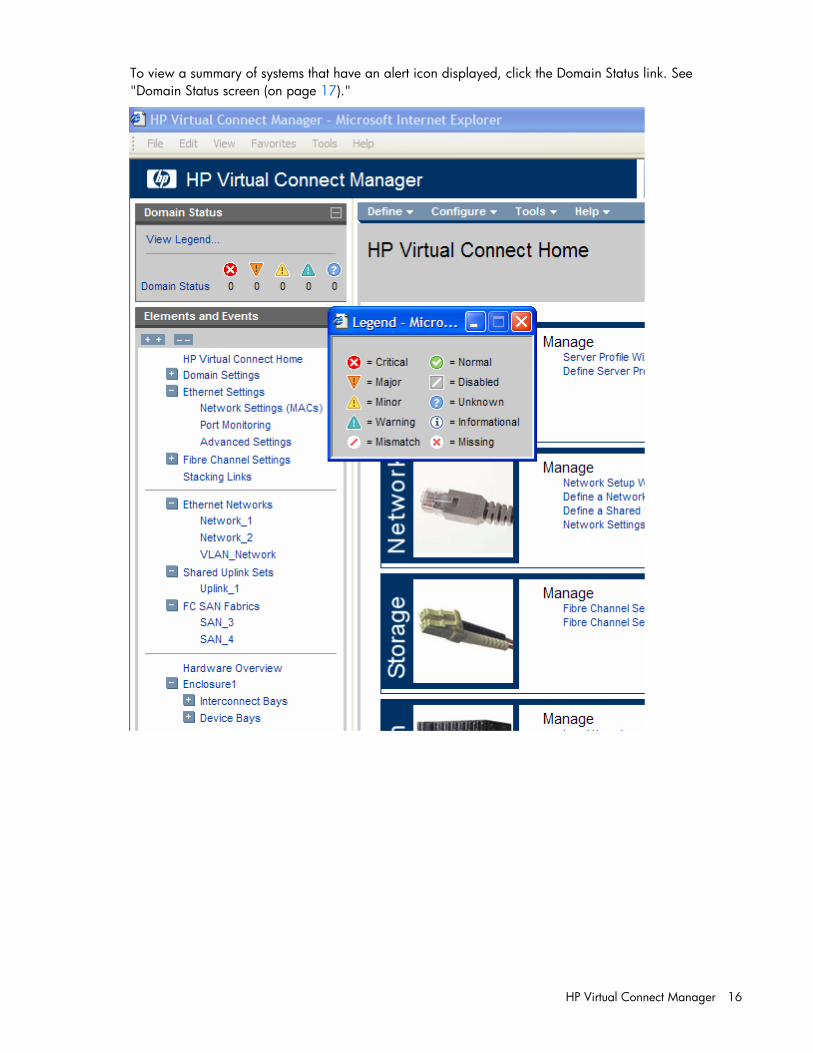
Domain Status summary The Domain Status summary provides a count of Virtual Connect elements that are in an alert status other than OK. Virtual Connect elements summarized here include networks, shared uplink sets, server profiles, interconnect modules, and server blades.
HP Virtual Connect Manager 16
To view a summary of systems that have an alert icon displayed, click the Domain Status link. See "Domain Status screen (on page 17)."

HP Virtual Connect Manager 17
Domain Status screen This screen provides an overall domain status and a detailed summary of systems that currently have an alert status other than OK.
To view detailed information about a device, click that device name in the list. Additional information on the issue might be available as a tooltip for the severity icon. To see this information, mouse over the severity icon.

HP Virtual Connect Manager 18
Enclosures View This graphical representation consists of an enclosure front view and rear view. To display a window with information about a particular device, mouse over that device in this graphical view.
The Enclosures view provides status on each device in the enclosure and the option to select an individual device for more detailed information.
To display the Enclosures View screen, click Hardware Overview in the left window.

HP Virtual Connect Manager 19
Enclosures view (multiple enclosures) When more than one enclosure has been imported, each enclosure is displayed on the Enclosures View screen.
Status icon definitions
Icon Status Description
Critical A device or system is indicating a potential outage.
Incompatible/ Mismatch
A profile is incompatible with assigned hardware.
Missing A device or item is missing.
(orange)
Major A device or system is degraded.
(yellow)
Minor A device or system is degraded.
Disabled A device or item is disabled.
(blue)
Warning A device is initializing or susceptible to outage.
Unknown Status of this item is unknown.

HP Virtual Connect Manager 20
Icon Status Description
Normal Status of this line item is okay.
Informational
—
Other icon definitions
Icon Description
Mouse over to view specific help for the associated field.
The UID/PID of this line item is not illuminated.
The UID/PID for this line item is illuminated.
(green)
The server blade is powered on.
(amber)
The server blade is powered off.
Click to view a printable report of the onscreen summary. This icon is not available if no report function is available for that screen.
Export support information Virtual Connect Manager enables users to generate a support log, which can then be exported for technical support assistance.
To generate a support log, select Export Support Information from the Tools pull-down menu. Allow several minutes for Virtual Connect Manager to collect all of the information. After the information is collected, you are prompted to save the information file locally.
Following is a list of the support information that is collected:
• System Log files
• VC Manager trace files
• Web Server Log file
• VC Manager configuration files
• VC-Enet module database content in XML format
• VC-FC module database content in XML format
• Ethernet switch status and configuration information
• Operating system status information
• Directory listings
• Boot Loader environment variables

HP Virtual Connect Manager 21
Reset Virtual Connect Manager Users must have Administrative privileges to reset the Virtual Connect Manager. In a multi-enclosure environment, the Ethernet modules in bays 1 and 2 of the primary enclosure host the Virtual Connect Manager.
To reset the Virtual Connect Manager application running on the primary Virtual Connect Ethernet module, select Reset Virtual Connect Manager from the Tools pull-down menu. The Reset Virtual Connect Manager screen is displayed.
• If the Force Failover checkbox is selected and a Virtual Connect Ethernet module is available in the alternate interconnect bay (interconnect Bays 1 and 2 can host the Virtual Connect Manager), the GUI counts down from 90 seconds. Then the GUI is redirected to the alternate Virtual Connect Ethernet module for logon after the Virtual Connect Manager has restarted.
• If the Force Failover checkbox is not selected or a Virtual Connect Ethernet module is not available in the alternate interconnect bay, the GUI counts down from 90 seconds, the Virtual Connect Manager restarts on the current Virtual Connect Ethernet Module, and the user is presented the logon screen for the current Virtual Connect Ethernet module after the Virtual Connect Manager has restarted.
When resetting the Virtual Connect Ethernet module, Virtual Connect Manager is temporarily unavailable to the user. If failover is specified and a standby Virtual Connect Ethernet module is available, users are logged off and must reconnect using the standby Virtual Connect Ethernet module IP address.
Recovering remote enclosures If a previously saved configuration file is restored, the OA is reset to factory defaults, or the OA associated with the remote enclosure is replaced, then the credentials of the remote enclosure must be restored. If the IP link between the primary enclosure OA and the remote enclosure OA is lost, the remote enclosure is also marked as NO-COMM. Ensure network connectivity before attempting credentials recovery.

Domain management 22
Domain management
Domain overview A basic Virtual Connect domain includes a single HP c-Class BladeSystem c7000 Enclosure for a total of 16 servers (or up to 32 servers if the double-dense option is enabled), or a single HP c-Class BladeSystem c3000 Enclosure for a total of 8 servers (or up to 16 servers if the double-dense option is enabled). Within the domain, any server blade can access any LAN or SAN connected to a VC module, and a server blade can be used as a spare for any server blade within the same enclosure.
Version 2.10 and higher supports multiple enclosures, allowing up to four c7000 enclosures to be managed within a single Virtual Connect domain for a total of 128 servers. Multiple enclosure domains are not supported on c3000 enclosures.
By stacking (cabling) the Ethernet modules within the domain and connecting the FC modules to the same set of FC SANs, every server blade in the domain can be configured to access any external network connection. With this configuration, the Virtual Connect Manager can deploy and migrate a server blade profile to any server in the Virtual Connect domain without the need to change external LAN or SAN configurations.
Back up the Virtual Connect domain configuration each time changes are made. While the configuration is saved in non-volatile memory and check-pointed to the neighboring module, HP recommends saving the configuration external to the enclosure.
Enclosure serial numbers The enclosure serial number is used by the Virtual Connect Manager to associate a Virtual Connect domain with a particular enclosure. The enclosure serial number can be altered for maintenance purposes, such as replacement of the enclosure midplane. For more information, see SET ENCLOSURE SERIAL_NUMBER in the HP BladeSystem Onboard Administrator Command Line Interface User Guide.
• Enclosure serial numbers are unique as shipped from the factory, and must remain unique for proper Virtual Connect Manager operation. Use care when altering the enclosure serial number to ensure that serial numbers are unique within the management network.
• After an enclosure is imported into a domain, do not change the serial number. The enclosure must have the enclosure serial number that was present when imported initially. It cannot be replaced with an enclosure that has a different serial number.
• In the event of an enclosure failure, the replacement enclosure must have the serial number set to that of the failed enclosure before it is placed into the VC domain.
In an existing VC domain, if the enclosure serial number is changed from the OA with the set enclosure serial-number command, HP recommends that all the VC Ethernet modules be reset through the OA so that the new enclosure number is propagated to all the modules in the enclosure.

Domain management 23
Firmware updates To update firmware, use the HP BladeSystem c-Class Virtual Connect Support Utility. For more information on installing the firmware, see the HP BladeSystem c-Class Virtual Connect Support Utility documentation on the HP website (http://www.hp.com/go/bladesystem/documentation).
When upgrading to v3.00, any SAN fabrics previously using the static login distribution method are redefined to use dynamic login distribution. Servers will lose connectivity during the upgrade; therefore, HP recommends upgrading to v3.00 only during scheduled downtime.
To help ensure proper operation, clear the browser cache and reload the browser after firmware updates.
Downgrading from v2.30 to a pre-v2.00 version of the VC firmware is not supported if HP Virtual Connect Flex-10 modules are installed in an enclosure because it might not be possible to log in to the Virtual Connect Manager after the downgrade. To downgrade to an older version of Virtual Connect, remove all HP Virtual Connect Flex-10 modules from the enclosure, administratively remove the modules, and then perform the downgrade.
Downgrading from v2.30 to a pre-v2.00 version of the VC firmware is not supported if profiles contain Flex-10 connections because it might not be possible to log in to the Virtual Connect Manager after the downgrade. Virtual Connect defines Flex-10 connections as the connections between FlexNICs and the HP Virtual Connect Flex-10 module or an empty interconnect bay. To downgrade to an older version of Virtual Connect, remove all the Flex-10 connections from the profile, administratively remove the HP Virtual Connect Flex-10 modules, and then perform the downgrade.
When created with HP VC 8Gb 24-port FC modules present in the domain, the VC configuration file is not compatible with the configuration files created by versions of VC previous to v2.10. If the VC firmware is downgraded to any pre-v2.10 versions, re-importing of the VC domain is required.
Since downgrade from VC v3.xx to a pre-v3.00 will result in the loss of domain configuration, it is recommended to backup domain configuration prior to upgrade from pre-v3.00 release to v3.xx.
If SNMP trap destinations are configured, during the firmware update process several SNMP traps will be generated including but not limited to the Domain Role Change and Port Status Change traps.
Domain Settings (Domain Configuration) screen Use this screen to change the domain name or delete a domain.
The Remove from Domain feature (also known as administrative removal) enables users to remove an interconnect module from the Virtual Connect domain without having to delete the entire domain, or having the bay permanently configured for a specific interconnect module type. After an Ethernet module has been physically removed from the enclosure and none of its ports are part of an Ethernet network and/or Shared Uplink Set, the module can be removed from the Virtual Connect domain. A FC module can be administratively removed when none of its fabrics are in use by a profile.

Domain management 24
For additional information, see "Interconnect Bay summary screen (Ethernet module) (on page 128)" and "Administrative module removal (on page 142)."
The following table describes the available actions in the Domain Settings (Domain Configuration) screen. Clicking another link in the pull-down menu or left navigation window causes current edits that have not been applied to be lost.
Task Action
Change the domain name Enter the revised domain name, and then click Apply.
Display single-dense server bays Click the checkbox next to the appropriate selection. Available if double-dense compatibility is selected during import.
Delete a domain Verify that the correct domain name is displayed, and then click Delete Domain. See "Deleting a domain (on page 24)."
Save changes and remain on this screen
Click Apply.
Clear the enclosure checkboxes Click Cancel.
Deleting a domain
CAUTION: Deleting a domain returns all settings to factory default. This action cannot be undone.
1. Power off all servers that are associated with profiles. See "Server Bay Status screen (on page 150)."
2. Navigate to the Domain Settings (Domain Configuration) screen (on page 23).
3. Click Delete Domain. A domain name verification window is displayed.

Domain management 25
4. Enter the name of the domain to be deleted. This should be the name of the domain you are currently logged into, displayed in the Virtual Connect Domain Name box on the Domain Settings (Domain Configuration) screen (on page 23).
5. Click OK.
If deleting a domain that was using MAC addresses predefined by HP, the administrator should also update the "Teaming" driver configuration file on the host OS. Otherwise, the driver reinitializes to the saved MAC address predefined by HP and not the factory default value.
Domain Settings (Domain IP Address) screen Use this screen to set a domain IP address for the Virtual Connect domain.
The optional domain IP address setting allows for a consistent IP address that is independent of the interconnect module on which it is running. If set, this IP address must be unique within the network and must be different than the IP address of the module itself. If this IP address is not set, the VC Manager can still be reached through the IP address of the host Virtual Connect Ethernet module.
To use an optional domain IP address, select the Use Domain IP address checkbox, and then enter the IP Address, Subnet Mask, and Default Gateway.
NOTE: Even if a domain IP address is provided, the normal IP address assigned to the interconnect bay can still be used.
The following table describes the available actions in the Domain Settings (Domain IP Address) screen. Clicking another link in the pull-down menu or left navigation window causes current edits that have not been applied to be lost.
Task Action
Use a VC domain IP address Select the box next to Use Virtual Connect Domain IP Address, and then enter the IP Address, Subnet Mask, and Gateway.

Domain management 26
Task Action
Clear unsaved changes on the screen Click Clear.
Save changes and remain on this screen
Click Apply.
Cancel without saving changes Click Cancel.
Domain Settings (Domain Enclosures) screen Use this screen to import, delete, or add enclosures in the domain.
Multiple enclosures are supported only if a VC-Enet module is running in bay 1 and bay 2 of the primary enclosure.
For additional information on adding and importing a remote enclosure and connecting multiple enclosures, see the HP Virtual Connect for c-Class BladeSystem Setup and Installation Guide.
The following table describes the columns within the Domain Settings (Enclosures) screen.
Column Description
Enclosure ID Assigned ID of the enclosure
Enclosure name Name of the enclosure
Enclosure serial number
Serial number of the enclosure
Rack name Name of the rack (assigned through the Onboard Administrator)
OA IP Address Local Enclosure indicates this enclosure is managed by the local OA

Domain management 27
Column Description
Status Displays whether the enclosure has been imported
Adding and importing a remote enclosure Adding and importing a remote enclosure requires full domain and server privileges. Virtual Connect Manager supports up to four c7000 enclosures in a single domain.
To add a remote enclosure:
1. Click Find on the Domain Settings (Domain Enclosures) screen (on page 26).
2. Type in the following information:
o OA IP Address
o OA User Name
o OA Password
3. Click OK.
4. Select the box next to the discovered enclosure.
IMPORTANT: No more than four enclosures can be found or imported. If an enclosure is unintentionally found, it can be removed by clicking Delete.

Domain management 28
5. Click Import.

Domain management 29
Virtual Connect Manager imports the enclosure and provides status information.
Removing a remote enclosure To remove a remote enclosure, disassociate all profiles, networks, port sets, and port monitors from the enclosure. If the enclosure is currently in a No-COMM state, the remote enclosure remains in VC Mode. Take the enclosure out of VC mode manually with the OA command line for that enclosure.
To remove a remote enclosure:
1. Go to the Domain Settings (Domain Enclosures) screen (on page 26).
2. Select the checkbox next to the enclosure to be removed.
3. Click Delete.
Domain Settings (Backup/Restore) screen Use this screen to create a backup file of the Virtual Connect domain configuration or to restore a configuration that has been lost. The domain configuration includes network definitions, MAC address settings, WWN settings, Fibre Channel fabric settings, local user accounts, and server profile definitions. The backup file stores the same information that is check-pointed between the active and standby modules during normal operation.

Domain management 30
IMPORTANT: Virtual Connect Manager cannot use backup configurations created with previous versions of Virtual Connect Manager. For example, if you are currently using v2.01, you cannot use a backup configuration that was created using v1.20.
To back up a domain configuration:
1. Click Backup Configuration.
2. Navigate to the hard drive location for the backup file.
3. Name the file (usually the domain name), and then click Save.
To restore a domain configuration:
1. Enter or browse to the backup file.
2. Select the file.
3. Select the Ignore enclosure serial number in restored configuration file checkbox to restore a configuration that was generated on another enclosure. If this item is not selected, a configuration generated on another enclosure is rejected.
4. Select the Disallow restore of 1.1x configuration file checkbox to restore the firmware to a revision other than what is stored in the configuration file.
5. Click Restore Configuration.
6. Confirm the domain configuration to be restored, and then click OK.
If restoring a configuration file that has multiple enclosures, each remote enclosure must be re-authenticated for security reasons.
For additional information, see "Recovering remote enclosures (on page 21)."

Domain management 31
Domain Settings (Local Users) screen
The first time this screen appears, the only local user account is the Administrator account, which has domain privileges. The Administrator account cannot be deleted or have domain privileges removed. However, the Administrator password can be changed. The default Administrator password is identified on the Default Network Settings label on the Ethernet module in interconnect bay 1. To reset the Administrator password to the factory default, see the information on resetting the administrator password and DNS settings in the HP Virtual Connect for c-Class BladeSystem Setup and Installation Guide.
The following tasks can be performed on this screen:
• To create a new local user account, click Add User. The User Settings screen appears.
• To edit attributes of a defined local account, select the user name from this screen.
• To delete a user account, click the Delete icon for that line item, and then click Apply.

Domain management 32
• To enable strong passwords or enable local users, click Advanced.
To enable the use of strong passwords, select the Require Strong Passwords checkbox. Use the up and down arrows to select a password length between 3 and 40 characters. With strong passwords enabled, passwords must also contain at least one character from three of the following four categories:
• Upper-case character
• Lower-case character
• Numeric character
• Non-alphanumeric character
To enable local users, select the Enable Local Users checkbox. To disable local users, deselect the Enable Local Users checkbox. If you disable local users before properly setting up both directory services groups and directory services, you cannot log in to the Virtual Connect Manager.
The following table describes the columns within the Domain Settings (Local Users) screen.
Column Description
User Name The user name must begin with a letter and is case sensitive.
Privileges Shows what privileges the user has (Domain, Network, Storage, and/or Server)
Full Name The user's full name. All users can modify their own full name.

Domain management 33
Column Description
Contact Contact information for the user account. The contact information can be the name of an individual, a telephone number, or other useful information. All users can modify their own contact information.
Account Status Shows whether a user account is enabled or disabled.
Delete Displays the Delete icon. Click the Delete icon, and then click Apply to delete that line item.
The following table describes the available actions in the Domain Settings (Local Users) screen. Clicking another link in the pull-down menu or left navigation window causes current edits that have not been applied to be lost.
Task Action
Edit user properties Click on that user in the User Name column.
Add a new user Click Add User.
Delete a user Click the Delete icon in the row of the user to delete, and then click Apply.
Enable or disable strong passwords
Click Advanced, and then select or deselect the checkbox.
Enable or disable local users Click Advanced, and then select or deselect the checkbox.
Return to the HP Virtual Connect Manager homepage
Click Cancel.

Domain management 34
Add new user
Observe the following user settings guidelines:
• Username is a required field.
• A username must contain an alpha-numeric value with 1 to 13 characters.
• A password must contain an alpha-numeric value with 3 to 40 characters.
• If strong passwords are enabled, the password must contain the administrator-designated number of characters, and at least one character from three of the following four categories:
o Upper-case character
o Lower-case character
o Numeric character
o Non-alphanumeric character
Up to 32 local user accounts can be created.
Each account can be set up to have a combination of up to four access privileges:
• Domain
o Define local user accounts, set passwords, define roles
o Import enclosures
o Name the VC domain
o Set the domain IP address

Domain management 35
o Administer SSL certificates
o Delete the VC domain
o Save configuration to disk
o Restore the configuration from a backup
o Configure SNMP settings
• Networking
o Configure network default settings
o Select the MAC address range to be used by the VC domain
o Create, delete, and edit networks
o Create, delete, and edit shared uplink sets
o Configure Ethernet SNMP settings
• Server
o Create, delete, and edit server Virtual Connect profiles
o Assign and unassign profiles to device bays
o Select and use available networks
o Select serial numbers (logical) and UUIDs (logical) to be used by server profiles
o Power on and off server blades within the enclosure
• Storage
o Select the WWNs to be used by the domain
o Set up the connections to the external FC Fabrics
o Configure FC SNMP settings
It is possible to create a user with no privileges. This user can only view status and settings.
NOTE: The vcmuser_ account is an internal Onboard Administrator account created and used by Virtual Connect Manager to communicate with the Onboard Administrator. This account can show up in the Onboard Administrator system log. This account cannot be changed or deleted.

Domain management 36
Directory Settings (Directory Server) screen This screen enables Administrators to set up an LDAP server to authenticate users accessing the CLI or GUI based on user name, password, and role. Beginning with version 1.31 of Virtual Connect Manager, users can test an LDAP configuration before applying it. For more information, see "Test LDAP authentication (on page 39)."
The following table describes the fields within the Directory Settings (Directory Server) screen.
Field Description
Enable LDAP Authentication Select to enable LDAP authentication.
Directory Server Address The IP address or the DNS name of the domain of the directory service
Directory Server SSL Port The port used for LDAP communications. The default port is port 636.
Search Context 1 First searchable path used to locate the user when the user is trying to authenticate using directory services
Search Context 2 Second searchable path used to locate the user when the user is trying to authenticate using directory services
Search Context 3 Third searchable path used to locate the user when the user is trying to authenticate using directory services
Use NT Account Name Mapping (DOMAIN/Username)
Select to use NT account name mapping.

Domain management 37
Directory Settings (Directory Groups) screen Use this screen to manage the Directory Group settings for Virtual Connect Manager.
The following table describes the fields within the Directory Settings (Directory Groups) screen.
Field Description
Group Name The Directory Server group name. Microsoft Active Directory servers have a reverse mapping from the user to the groups the user belongs to. To determine if the user is a member of the group, other servers might need to combine the Group Name with a Search Context to look up the group. To open the Edit LDAP Group window, click the Group Name. Starting with Virtual Connect v1.31, nested group memberships (groups that are members of groups) are searched to a depth of up to four levels when determining group membership.
Privilege Level Zero or more privileges (Domain, Network, Storage, Server) assigned to the group. A user can be a member of multiple groups, in which case the privileges are cumulative. If the user is only a member of a group (or groups) with no privileges, the user can log in and view the Virtual Connect configuration, but cannot make any changes. If a user is not a member of any group, the user cannot log in.
Description A text description for the group.
Domain management 38
To remove a group from the configuration, click the Delete icon.
To open the Add LDAP Group page, click New.
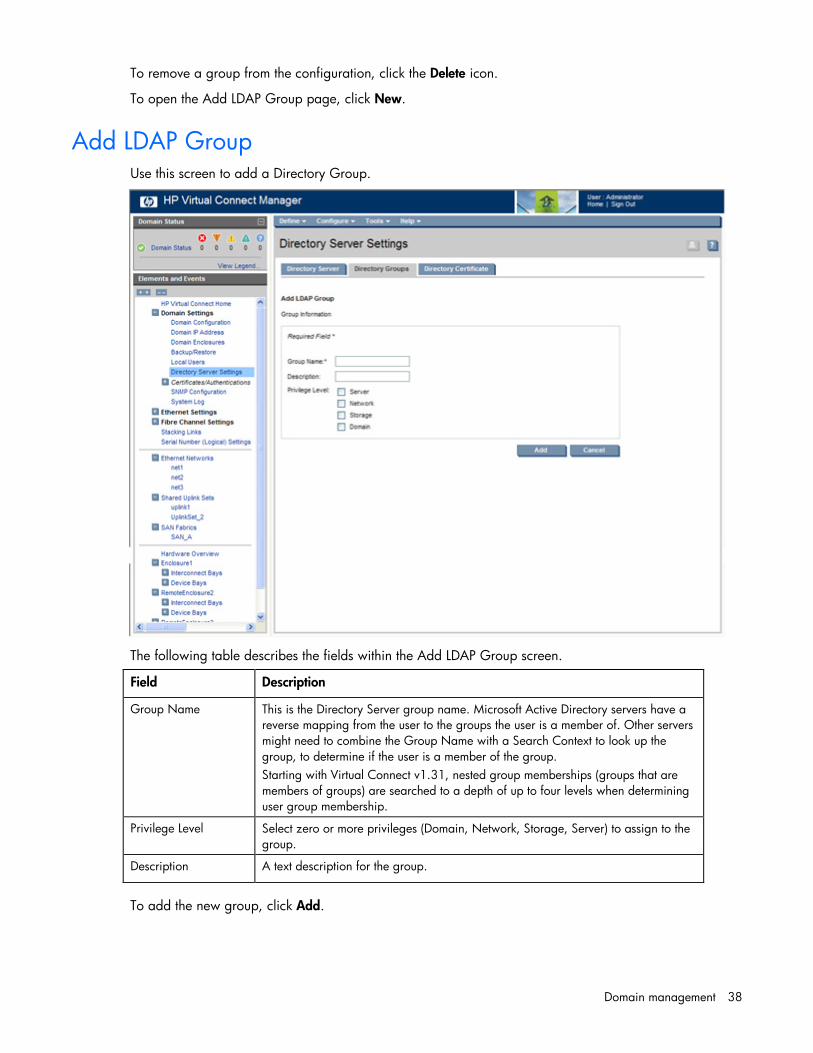
Add LDAP Group Use this screen to add a Directory Group.
The following table describes the fields within the Add LDAP Group screen.
Field Description
Group Name This is the Directory Server group name. Microsoft Active Directory servers have a reverse mapping from the user to the groups the user is a member of. Other servers might need to combine the Group Name with a Search Context to look up the group, to determine if the user is a member of the group. Starting with Virtual Connect v1.31, nested group memberships (groups that are members of groups) are searched to a depth of up to four levels when determining user group membership.
Privilege Level Select zero or more privileges (Domain, Network, Storage, Server) to assign to the group.
Description A text description for the group.
To add the new group, click Add.

Domain management 39
Directory Settings (Directory Certificate) screen Directory Certificates provide authentication of the Directory Server. There are two ways to verify the identity of the Directory Server:
• Install certificates that complete a certificate chain to a root Certificate Authority.
• Install a certificate that exactly matches the certificate provided by the Directory Server.
To upload a certificate, select the certificate from the list, and then click Certificate Upload.
If no certificates are installed, the Directory Server is not authenticated (although the connection to the Directory Server must be established using SSL).
The following table describes the columns within the Directory Settings (Directory Certificate) screen.
Column Description
MD5 Fingerprint Unique fingerprint of the certificate, calculated using cryptographic hash function Message-Digest algorithm 5 (MD5). This fingerprint can be used to further verify that the correct certificate is being used.
Version Version of the certificate
Valid from The date and time when this certificate became valid
Valid until The date and time when this certificate becomes invalid
Delete Click X in the line of the certificate to delete.
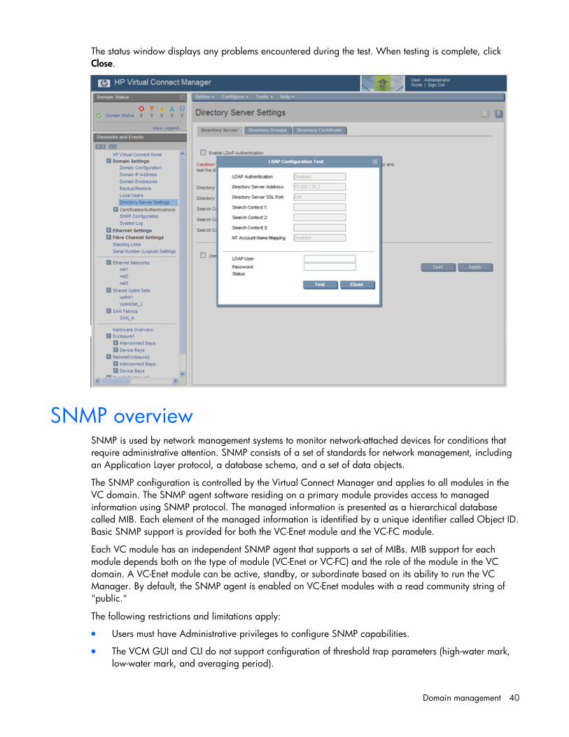
Test LDAP authentication Beginning with v1.31 of Virtual Connect Manager, local users can test their LDAP configuration before making the configuration active.
To test an LDAP configuration:
1. Be sure that LDAP group settings are configured.
2. Be sure that any LDAP certificates are installed.
3. Access the Directory Settings (Directory Server) screen (on page 36).
4. Enter the LDAP configuration information.
5. Click Test.
6. Enter a valid username and password.
7. Click Test.
Domain management 40
The status window displays any problems encountered during the test. When testing is complete, click Close.
SNMP overview SNMP is used by network management systems to monitor network-attached devices for conditions that require administrative attention. SNMP consists of a set of standards for network management, including an Application Layer protocol, a database schema, and a set of data objects.
The SNMP configuration is controlled by the Virtual Connect Manager and applies to all modules in the VC domain. The SNMP agent software residing on a primary module provides access to managed information using SNMP protocol. The managed information is presented as a hierarchical database called MIB. Each element of the managed information is identified by a unique identifier called Object ID. Basic SNMP support is provided for both the VC-Enet module and the VC-FC module.
Each VC module has an independent SNMP agent that supports a set of MIBs. MIB support for each module depends both on the type of module (VC-Enet or VC-FC) and the role of the module in the VC domain. A VC-Enet module can be active, standby, or subordinate based on its ability to run the VC Manager. By default, the SNMP agent is enabled on VC-Enet modules with a read community string of "public."
The following restrictions and limitations apply:
• Users must have Administrative privileges to configure SNMP capabilities.
• The VCM GUI and CLI do not support configuration of threshold trap parameters (high-water mark, low-water mark, and averaging period).

Domain management 41
• For Flex-10 connections, threshold and link state change traps reflect the state of the entire physical port. These traps are not generated for individual FlexNICs. For more information on Flex-10 connections, see "Flex-10 overview (on page 94)."
The following table provides a list of MIBs and where they are supported.
MIB VC-Enet VC-FC
RFC 2863 IF-MIB X —
RFC 4188 Bridge-MIB X —
RFC 3418 SNMP v2 MIB X X
Compaq System Info MIB X X
Compaq Host MIB X X
Compaq Rack MIB — X*
Network Mgmt X —
IP-MIB X —
Fibre Alliance MIB (FC Mgmt Integ) — X
Fabric Element MIB — X
VC Module MIB (VCM-MIB) X —
VC Domain MIB (VCD-MIB) X —
* Not supported by the HP 8Gb 24-Port FC module
The VC Module MIB is a VC-specific MIB that describes the state of a specific VC module. In addition to unique VC module attributes, it defines traps for reporting alerts on port statistics, such as throughput, errors, and discards. The VC Domain MIB combines domain-wide attributes with traps for state changes in VC managed objects.
The latest version of the VC-specific MIBs, 8.30b or higher, can be downloaded from the HP Systems Insight Manager "MIB Kit" site on the HP website (http://h18006.www1.hp.com/products/servers/management/hpsim/mibkit.html).
SNMP traps The following table provides a summary of the available SNMP traps.
Trap Category Severity MIB
cpqHoSWRunningStatusChangeTrap VCM Legacy Corresponds to the new value of cpqHoSWRunningStatus
CPQHOST-MIB
connUnitStatusChange VC-FC Other INFO FA-MIB
connUnitDeletedTrap VC-FC Other INFO FA-MIB
connUnitEventTrap VC-FC Other INFO FA-MIB
connUnitSensorStatusChange VC-FC Other CRITICAL FA-MIB
connUnitPortStatusChange VC-FC Port Status See table below FA-MIB
authenticationFailure* VC-FC Other CRITICAL SNMPv2-MIB
coldStart VC-FC Other CRITICAL SNMPv2-MIB
cpqHoSWRunningStatusChange VC-FC Other INFO CPQHOST-MIB

Domain management 42
Trap Category Severity MIB
authenticationFailure VC-Enet Other CRITICAL SNMPv2-MIB
Domain status change VCM Domain Status Corresponds to the name of the new state
VCD-MIB
StackingLinkRedundant status change VCM Domain Status Corresponds to the name of the new state
VCD-MIB
Module role change VCM Domain Status INFO VCM-MIB
Stale checkpoint VCM Domain Status WARNING VCD-MIB
Valid checkpoint VCM Domain Status NORMAL VCD-MIB
Enclosure status change VCM Domain Status Corresponds to the name of the new state
VCD-MIB
Network status change VCM Network Status Corresponds to the name of the new state
VCD-MIB
Fabric status change VCM Fabric Status Corresponds to the name of the new state
VCD-MIB
VC module status change VC-Enet Module Status or VC-FC Module Status
Corresponds to the name of the new state
VCD-MIB
Profile status change VCM Profile Status Corresponds to the name of the new state
VCD-MIB
Physical server change VCM Server Status Corresponds to the name of the new state
VCD-MIB
vcTesttrap VCM Domain Status INFO VCD-MIB
Enet IF-MIB LinkDown VC-Enet Port Status INFO IF-MIB
Enet IF-MIB LInkUp VC-Enet Port Status NORMAL IF-MIB
Input utilization above high-water mark
VC-Enet Port Threshold WARNING VCM-MIB
Input utilization below low-water mark VC-Enet Port Threshold NORMAL VCM-MIB
Output utilization above high-water mark
VC-Enet Port Threshold WARNING VCM-MIB
Output utilization below low-water mark
VC-Enet Port Threshold NORMAL VCM-MIB
Input errors above high-water mark VC-Enet Port Threshold WARNING VCM-MIB
Input errors below low-water mark VC-Enet Port Threshold NORMAL VCM-MIB
Output errors above high-water mark VC-Enet Port Threshold WARNING VCM-MIB
Output errors below low-water mark VC-Enet Port Threshold NORMAL VCM-MIB
* Only supported by the HP VC 8Gb 24-Port FC module
For more information, see the description field in the source code for individual MIBs.

Domain management 43
The VC-FC module generates connUnitPortStatusChange traps based on changes to the connUnitPortStatus element of the FA-MIB. The following table shows the mapping of connUnitPortStatusChange trap severities to the VC Domain MIB's trap severity definitions.
connUnitPortStatus value Severity
unknown INFO
unused INFO
ready NORMAL
warning WARNING
failure CRITICAL
nonparticipating INFO
initializing INFO
bypass INFO
ols MAJOR
other INFO
VC Module MIB traps The following table lists traps in the VC Module MIB.
Trap name Trap data Description
vcModRoleChange moduleRole The VCM role of the module has changed.
vcModInputUtilizationUp port identification The input line utilization on a port has exceeded its high-water mark for longer than 30 seconds. port is the index of the affected port in ifTable.
vcModInputUtilizationDown port identification The input line utilization on a port has dropped below its low-water mark for longer than 30 seconds. port is the index of the affected port in ifTable.
vcModOutputUtilizationUp port identification The output line utilization on a port has exceeded its high-water mark for longer than 30 seconds. port is the index of the affected port in ifTable.
vcModOutputUtilizationDown
port identification The output line utilization on a port has dropped below its low-water mark for longer than 30 seconds. port is the index of the affected port in ifTable.
vcModInputErrorsUp port identification ifInErrors
The input error count on a port has exceeded its high-water mark for longer than the error averaging period. port is the index of the affected port in ifTable.
vcModInputErrorsDown port identification ifInErrors
The input error count on a port has dropped below its low-water mark for longer than the error averaging period. port is the index of the affected port in ifTable.
vcModOutputErrorsUp port identification ifOutErrors
The output error count on a port has exceeded its high-water mark for longer than the threshold averaging period. port is the index of the affected port in ifTable.
vcModOutputErrorsDown port identification ifOutErrors
The output error count on a port has dropped below its low-water mark for longer than 30 seconds. port is the index of the affected port in ifTable.
Domain management 44
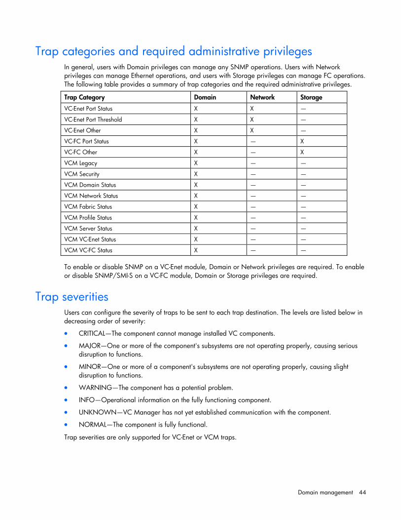
Trap categories and required administrative privileges In general, users with Domain privileges can manage any SNMP operations. Users with Network privileges can manage Ethernet operations, and users with Storage privileges can manage FC operations. The following table provides a summary of trap categories and the required administrative privileges.
Trap Category Domain Network Storage
VC-Enet Port Status X X —
VC-Enet Port Threshold X X —
VC-Enet Other X X —
VC-FC Port Status X — X
VC-FC Other X — X
VCM Legacy X — —
VCM Security X — —
VCM Domain Status X — —
VCM Network Status X — —
VCM Fabric Status X — —
VCM Profile Status X — —
VCM Server Status X — —
VCM VC-Enet Status X — —
VCM VC-FC Status X — —
To enable or disable SNMP on a VC-Enet module, Domain or Network privileges are required. To enable or disable SNMP/SMI-S on a VC-FC module, Domain or Storage privileges are required.
Trap severities Users can configure the severity of traps to be sent to each trap destination. The levels are listed below in decreasing order of severity:
• CRITICAL—The component cannot manage installed VC components.
• MAJOR—One or more of the component's subsystems are not operating properly, causing serious disruption to functions.
• MINOR—One or more of a component's subsystems are not operating properly, causing slight disruption to functions.
• WARNING—The component has a potential problem.
• INFO—Operational information on the fully functioning component.
• UNKNOWN—VC Manager has not yet established communication with the component.
• NORMAL—The component is fully functional.
Trap severities are only supported for VC-Enet or VCM traps.

Domain management 45
SNMP Configuration (VC-Enet) By enabling SNMP for VC-Enet modules, network management systems can monitor VC-Enet modules in the domain for events, such as warnings and errors, that might require corrective actions. The user must have network or domain administrator privileges to administer SNMP Enet settings.
The VC-Enet SNMP settings apply to all VC-Enet modules in the Virtual Connect domain.
The following table describes the fields within the SNMP Configuration screen.
Field name Description
Enable SNMP Select to enable SNMP
System Contact Specify a contact name for this system when SNMP is enabled
Read Community Controls SNMP read access when SNMP is enabled. The default value for read community string is "public". The read community string must always be set when SNMP is enabled.
SNMP Trap Destinations SNMP trap destination table. The maximum number of trap destinations allowed is five.
Destination User-designated name for the trap destination. The Destination name must be unique.
IP Address IPv4 address or DNS name for the trap destination

Domain management 46
Field name Description
Community String The Community String acts like a password for a given trap destination. The trap receiving application can use the community string to filter the incoming traps. Default: public
Format Format of the new trap. Select SNMPv1 or SNMPv2.
To add a trap destination, right-click on the header row of the destination table, and then select Add Destination. See "Adding an SNMP trap destination (on page 46)."
To edit or delete a trap destination, right-click on that trap destination row, and then select Edit Destination or Delete Destination.
To apply changes made on this screen, click Apply.
Adding an SNMP trap destination To add an SNMP trap destination, right-click on the header row of the SNMP Trap Destination table.
1. Enter a unique name for the new trap being added. No spaces are allowed.
2. Enter the IPv4 address or DNS name for the trap destination.
3. Select the Trap Format: SNMPv1 or SNMPv2.
4. Enter the SNMP trap community string for the specified trap. The default is "public."

Domain management 47
For VC-Enet modules, the maximum trap community string length is 39.
For VC-FC modules, the maximum trap community string length is 24.
5. Click OK to save the information and return to the main SNMP configuration screen, or continue and select trap categories or trap severities.
If you enter information that is invalid (for example, if you use a space in the Destination name), a red box appears around that field. Mouse over the box to see information regarding the error.
Select trap categories
Selecting a trap category allows multiple traps to be enabled or disabled as a group.
To select VC-Enet or VC-FC trap categories, click the checkbox. To select a VCM trap category, do one of the following:
• Highlight the item, and then click the right arrow.
• Highlight the item, and then drag and drop it into the right window.
Select trap severities
To select a trap severity, do one of the following:
• Highlight the item, and then click the right arrow.
• Highlight the item, and then drag and drop it into the right window.
For a definition of trap severities, see "Trap severities (on page 44)." When a trap is received with the severity listed in the right window, it is sent to the trap destination.
If you do not have the required privileges to select a category, that section is disabled. For a listing of trap categories and the required administrative privileges, see "Trap categories and required administrative privileges (on page 44)."
SNMP Configuration (VC-FC) By enabling SNMP for VC-FC modules, network management systems can monitor the VC-FC modules in the domain for events, such as warnings and errors, that might require corrective actions. The user must have storage or domain administrator privileges to administer SNMP FC settings.

Domain management 48
The VC-FC SNMP settings apply to all VC-FC modules in the VC domain.
The following table describes the fields within the SNMP Configuration screen.
Field name Description
Enable SNMP Select to enable SNMP
System Contact Specify a contact name for this system when SNMP is enabled
Read Community Controls SNMP read access when SNMP is enabled. The default value for read community string is "public". The read community string must always be set when SNMP is enabled. The maximum length is 39 characters.
SNMP Trap Destinations SNMP trap destination table.
Destination User-designated name for the trap destination. The Destination name must be unique.
IP Address IPv4 address or DNS name for the trap destination
Community String The Community String acts like a password for a given trap destination. The trap receiving application can use the community string to filter the incoming traps. Default: public
Format Format of the new trap. Select SNMPv1 or SNMPv2.
To add a trap destination, right-click on the header row of the destination table, and then select Add Destination. See "Adding an SNMP trap destination (on page 46)."

Domain management 49
To edit or delete a trap destination, right-click on that trap destination row, and then select Edit Destination or Delete Destination.
To apply changes made on this screen, click Apply.
SMI-S overview The ability to enable or disable SMI-S is not available on the HP VC 8Gb 24-Port FC module. The SMI-S was created by SNIA to standardize storage management solutions. SMI-S replaces multiple disparate managed object models, protocols, and transports with a single object-oriented model for each type of component in a storage network. SMI-S enables management applications (such as HP SIM) to support storage devices from multiple vendors quickly and reliably because they are no longer proprietary. SMI-S detects and manages storage elements by type, not by vendor.
Users must have storage or domain administrative privileges to configure SMI-S capabilities.
System Log screen The System Log screen displays logged information of events within Virtual Connect Manager.
To access the System Log screen, click on System Log in the left navigation pane, or select System Log from the Tools pull-down menu.
Events are logged with the most recent event displayed at the end of the list. Use the scroll bar on the right of the screen to scroll through the list if it is longer than the display box. When the log reaches maximum capacity, the oldest logged event is automatically deleted as new events are added.
Click Refresh to display the most current information.
NOTE: The vcmuser_ account is an internal Onboard Administrator account created and used by Virtual Connect Manager to communicate with the Onboard Administrator. This account can show up in the Onboard Administrator system log. This account cannot be changed or deleted.

Domain management 50

Domain management 51
System Log Configuration
Use this screen to view or set remote log destination settings.
Column Description
Log host The IP address or the DNS of the configured remote log destination
Log severity Severity of the log messages that should be sent to the specified destination. Valid values include "Critical", "Error", "Warning", and "Informational".
Transport The transport protocol to be used for sending the log messages to the destination. Valid values include "TCP" and "UDP".
Port The port to be used on the destination to send the log messages. Valid values include 1 to 65536. The default value is 514.
Security Secure transmission of the log messages. Valid values include "None" and "STunnel". The default value is "None", and no encryption is used during transmission. The "STunnel" option can be used only if the transport protocol used is TCP.
Date Format The timestamp format for the log messages. Valid values include "RFC3164" (Nov 26 13:15:55) and "ISO8601" (1997-07-16T19:20:30+01:00). The default value is "RFC3164".
Enabled Enables or disables the remote log destination
To define a new remote log destination, click Define Target.
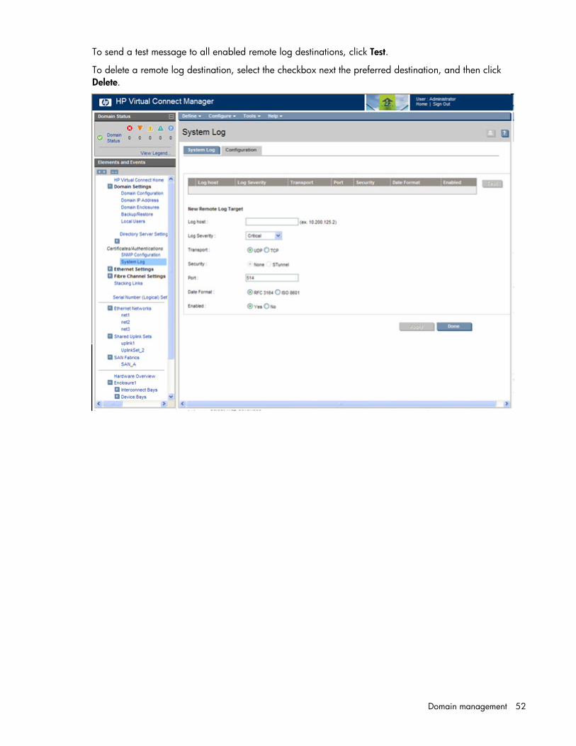
Domain management 52
To send a test message to all enabled remote log destinations, click Test.
To delete a remote log destination, select the checkbox next the preferred destination, and then click Delete.

Network management 53
Network management
Networks overview The Virtual Connect Ethernet module uses standard Ethernet bridge circuitry with special firmware so that it functions as a configurable Ethernet port aggregator. For a specific external data center connection, only the selected server Ethernet NIC ports are visible on what appears to be an isolated, private, loop-free network. The Virtual Connect Ethernet module uplinks do not participate in the data center Spanning Tree Protocol or other switch management protocols that could disrupt the data center network.
The Virtual Connect Ethernet module uplinks support link aggregation, link layer discovery protocol (LLDP), and VLAN tagging. VLAN tagging enables uplinks to be shared to carry multiple networks. Virtual Connect allows users to identify an associated network as the native VLAN, causing all untagged incoming Ethernet packets to be placed onto the designated network. Only one associated network can be designated as the native VLAN. All outgoing Ethernet packets are VLAN tagged.
Each network defined within Virtual Connect may have one or more uplinks. Virtual Connect independently ensures that no loops are created within the enclosure and that the resulting tree structure is optimized for the uplinks to the data center.
When multiple uplinks are used on a network, HP Virtual Connect Manager first verifies if any of the ports can be collected together into an aggregation group (requires connections to go from a single Virtual Connect Ethernet module to a single data center switch), and then it picks a single link (or aggregation group) as the connection to the external network. The remaining connections are blocked and held as standby ports.
TIP: To improve network performance and prevent unnecessary Spanning Tree Topology Change Notifications (TCN) on the network, configure Ethernet switches connected to Virtual Connect with the same Spanning Tree settings you would use when connecting to a server blade NIC. For Cisco switches, use the portfast command to enable ports connected to a VC-Enet module. This action ensures that link state changes on Virtual Connect do not cause a TCN.
Smart Link Enabling Smart Link configures the network so that if all external links lose their link to external switches, Virtual Connect drops the Ethernet link on all local server blade Ethernet ports connected to that network. This feature can be useful when using certain server network teaming (bonding) configurations.
Private Networks The Private Networks option provides extra networking security. When checked, the network is configured so that all server ports connected to it cannot communicate with each other within the Virtual Connect domain. All packets from servers are sent through the VC domain and out the uplink ports only. Servers on the network can only communicate with each other through an external Layer 3 router that redirects the traffic back to the VC domain.

Network management 54
Define Ethernet Network screen The Define Ethernet Network screen is accessible to all users with network privileges from the Define a Network link on the Virtual Connect Manager homepage or the Define pull-down menu.
The following table describes the fields within the Define Ethernet Network screen.
Field name Description
Network
Network Name Name of the network
Smart Link (on page 53) To enable Smart Link, edit the network settings after the network is created.
Private Network ("Private Networks" on page 53)
Select whether to designate (checked) or not designate (unchecked) this network as a private network.
Enable VLAN Tunneling ("Server VLAN Tagging Support" on page 69)
Select whether to enable (checked) or disable (unchecked) VLAN Tunneling (this option is not available if VLAN mapping is enabled). If enabled, VLAN tags are passed through the domain without any modification. If disabled, all tagged frames are discarded. If multiple networks are configured on any server port, this option cannot be modified.
External Uplink Ports
Use Shared Uplink Set Enables selection or creation of a shared uplink set
Port Network port locations (enclosure, bay, and port numbers)
Port Role Applicable when Failover Connection Mode is selected. The port can be designated as Primary or Secondary.
Port Status Displays the active link status and interface speed of the selected port
Connector Type Displays the type of connector on the port; for example, RJ-45
Connected to If the port is connected to a switch that supports LLDP, the switch MAC

Network management 55
Field name Description address and switch port appear. A link is provided to obtain more information about the far-end switch port.
PID When selected, sets/clears the port identifier color as blue on the VC-Enet module to aid in the location of the specific uplink. The PID status for the overall network also appears.
Speed/Duplex Pull-down menu to specify the speed and duplex (where applicable) of the uplink port. Half-duplex operations are not supported by the VC-Enet module.
The following table describes the available actions in the Define Ethernet Network Screen. Clicking another link in the pull-down menu or left-hand navigation window causes current edits that have not been applied to be lost.
Task Action
Enable Smart Link on the network being defined
Select the Smart Link checkbox.
Designate the network as a private network
Select the Private Network checkbox.
Enable VLAN tunneling Select the Enable VLAN Tunneling checkbox. This option is only available if the 'Tunnel VLAN Tags' radio button is selected on the Advanced Settings tab of the Ethernet Settings screen.
Set a custom value for preferred link connection speed or maximum link connection speed
Select the Advanced Network Settings checkbox.
Enable the selection or creation of a shared uplink set
Select the Use Shared Uplink set checkbox.
Add an external uplink port to the network
Click the Add Port drop-down box, and then select an available port.
Change the uplink interface port speed or disable the port
Click the drop-down box under Speed/Duplex, and then select a setting.
Change the connection mode Click the down arrow in the box next to Connection Mode, and then select Auto or Failover. For a description of these modes, see "Defining a network (on page 55)."
Delete an added port Left-click to select the line item, right-click to display a drop-down menu, and then select Delete.
Save changes and remain on this screen
Click Apply.
Cancel without saving changes and return to the summary screen
Click Cancel.
Defining a network To define a standalone network:
1. Enter a network name. The network name can be up to 64 characters in length (no spaces).
2. Select whether to enable (checked) or disable (unchecked) Smart Link (on page 53).
The checkbox is not available until an uplink is added to the network.

Network management 56
3. Select whether to designate (checked) or not designate (unchecked) this network as a private network ("Private Networks" on page 53).
4. Select whether to enable (checked) or disable (unchecked) VLAN tunneling ("Server VLAN Tagging Support" on page 69).
This option is only available if the 'Tunnel VLAN Tags' radio button was previously selected on the Advanced Settings tab of the Ethernet Settings screen.
5. If the network is to be used only internal to the Virtual Connect domain or enclosure, go to step 7 (do not add any external ports).
6. Use the Add Port pull-down menu to add one or more external ports. To ensure a high availability connection, select two or more ports.
Only available ports are listed, displaying the current port link status.
To create an internal network, which connects one server to another, do not select a port. Enter the network name, and then click Define Network.
7. Select the Connection Mode:
o Auto (recommended)—This mode enables the uplinks to attempt to form aggregation groups using IEEE 802.3ad link aggregation control protocol, and to select the highest performing uplink as the active path to external networks.
Aggregation groups require multiple ports from a single Virtual Connect Ethernet module to be connected to a single external switch that supports automatic formation of LACP aggregation groups. Multiple aggregation groups may be formed from the ports selected for the network. The highest performing aggregation group is selected as active, with other aggregation groups and individual links used as standby connections.
o Failover—If this mode is selected, set the port to Primary or Secondary. Only a single link is used as the active link to the external networks, with other ports used as standby connections.
8. Click Apply. The network is now defined and available for use in creating server profiles.
To define a network that uses an existing Shared Uplink Set, either use the Define/Edit Shared Uplink Set screen, or define the additional network as follows:
1. Enter the network name.
2. Select the Use Shared Uplink Set box.
3. Select an existing Network from the dropdown list or click the Create icon.
If the Create icon is selected, the Define a Shared Uplink Set screen appears so that a new Shared Uplink Set can be created.
4. Enter an external VLAN ID.
5. Click Apply.
IMPORTANT: For best performance, HP recommends limiting the number of VLANs on one shared uplink set to 128 and limiting the number of shared uplinks sets in one domain to two.
NOTE: By default, Virtual Connect supports Jumbo Frames up to 9KB.

Network management 57
Advanced Network Settings These settings affect only newly created profiles. Changing these settings does not affect any assigned profiles.
To set the speed, click the selection box, select a setting (100Mb to 10Gb), and then click OK.
• Set a Custom value for the Preferred Link Connection Speed.
This value is the default speed for server profile connections mapped to this network. The server administrator can override this setting on an individual profile connection.
• Set a Custom value for the Maximum Link Connection Speed.
This value is the maximum speed for server profile connections mapped to this network. The server administrator can override this setting on an individual profile connection.
For additional information, see "Multiple Networks Link Speed Settings (on page 72)."
Edit Ethernet Network screen To access this screen, click the network name under the Ethernet Networks link in the left VC Manager navigation window.
Use this screen to edit the properties of an existing network or to delete a network.

Network management 58
This screen has similar fields to the Define Ethernet Network screen (on page 54). This screen can only be edited by users with network privileges, but it is viewable by all authorized users.
The following table describes the fields within the Edit Network screen.
Field name Description
Network
Network Name Name of the network
Enabled Displays the current state of the network as enabled (checked) or disabled (unchecked)
Status Displays the current status of the network
PID PID status for the overall network
Advanced Network Settings If checked, displays additional selections for advanced network settings
Smart Link Shows whether Smart Link is enabled (checked) or disabled (unchecked)
Private Network Shows whether this network is designated (checked) or not designated (unchecked) as a private network
Enable VLAN Tunneling Shows whether VLAN tunneling is enabled (checked) or disabled (unchecked)
External Uplink Ports
Use Shared Uplink Set Enables selection or creation of a shared uplink set
Port Network port locations (enclosure, bay, and port numbers)
Port Role Applicable when Failover Connection Mode is selected. The port can be designated as Primary or Secondary.
Port Status Displays the current linked status of the selected port
Connector Type Displays the type of connector on the port; for example, RJ-45
Connected to If the port is connected to a switch that supports LLDP, the switch MAC address and switch port number appear. A link is provided to obtain more information about the far-end switch port.

Network management 59
Field name Description
PID When selected, this option sets/clears the port identifier color as blue on the VC E-net module to aid in the location of the specific uplink. The PID status for the overall network also appears.
Speed/Duplex Pull-down menu to specify the speed and duplex (where applicable) of the uplink port
The following table describes the available actions in the Edit Network Screen. Clicking another link in the pull-down menu or left-hand navigation window causes current edits that have not been applied to be lost.
Task Action
Enable or disable Smart Link on the network being defined
Select the Smart Link checkbox.
Designate or do not designate the network as a private network
Select the Private Network checkbox.
Enable or disable VLAN tunneling Select the Enable VLAN Tunneling checkbox. This option is only available if the 'Tunnel VLAN Tags' radio button is selected on the Advanced Settings tab of the Ethernet Settings screen.
Enable or disable the network Select the Enabled checkbox.
Set a custom value for preferred link connection speed or maximum link connection speed
Select the Advanced Network Settings checkbox.
Add an external uplink port to the network
Click the Add Port drop-down box, and then select an available port.
Change the uplink interface port speed or disable the port
Click the drop-down box under Speed/Duplex, and then select a setting.
Change the connection mode Click the down arrow in the box next to Connection Mode, and then select Auto or Failover. For a description of these modes, see "Defining a network (on page 55)."
Delete an added port Left-click the port to select it, right-click to display a menu, and then select Delete.
Save changes and remain on this screen
Click Apply.
Cancel without saving changes and return to the summary screen
Click Cancel.
If the network mappings are changed on the NIC ports, a link might not be re-established between the module and the ports of an NC364m mezzanine card.
If the server is rebooted, the link is established on all ports on both sides of the connection. Manually toggling the link from the server should also restore the link.
Ethernet Networks (External Connections) screen To access this screen, click the Ethernet Networks link in the left VC Manager navigation window, and then click the Summary tab.
To view a list of all defined Ethernet networks, click Ethernet Networks in the left window.

Network management 60
This summary screen displays the external connections for each network and is available to all authorized users.
The following table describes the columns within the summary table on the Ethernet Networks (Summary) screen.
Column name Description
Ethernet Networks Shows the overall network status and network name
PID Shows the PID state of the network
Shared Uplink Set (VLAN ID) Shows the name of the shared uplink set and its VLAN ID (if applicable)
Port Status Shows whether each individual port associated with the network is linked or unlinked and the current link speed
Connector Type Displays the type of connector on the port; for example, RJ-45
Connected to If the individual port is connected to a switch that supports LLDP, the switch MAC address and switch port appear. A link is provided to obtain more information about the far-end switch port.
Uplink Port Lists the status of the individual port and the location of the individual port (enclosure, bay, port)
The following table describes the available actions in the Ethernet Networks (Summary) screen. Clicking another link in the pull-down menu or left navigation window causes current edits that have not been applied to be lost.
Task Action
Sort list view Click the down arrow next to the Show box to display All Networks, or one specific network.
Edit a network Left-click on the network row, right-click to display a menu, and then select Edit.
Edit a shared uplink set Left-click on the shared uplink set row, right-click to display a menu, and then select Edit.

Network management 61
Task Action
Define a new network Right-click in the table to display a menu, and then click Add.
Delete a network Left-click on the network row, right-click to display a menu, and then select Delete. Type in the network name, and then click OK.
Illuminate the PID for all uplink ports associated with a network
Click on the circle next to the network in the list.
Ethernet Networks (Server Connections) screen To access this screen, click the Ethernet Networks link in the left VC Manager navigation window, and then click the Server Connections tab.
This summary screen lists the server ports connected to each network in the Virtual Connect domain. This screen is viewable by all authorized users.
The following table describes the columns within the Ethernet Networks (Server Connections) screen.
Column name Description
Network Name Name of the Network
(Profile) Name Name of the profile
(Profile) Status Overall status of the server profile
(Profile) Number Number of the profile
(Profile Connection) Status Shows the overall status of the individual server port
(Profile Connection) MAC Lists the MAC address for the server port
(Physical Server) Enclosure Enclosure number where the server resides
(Physical Server) Bay Bay number where the server resides.
(Physical Server) Model Model of the server.

Network management 62
The following table describes the available actions in the Ethernet Networks (Server Connections) screen. Clicking another link in the pull-down menu or left navigation window causes current edits that have not been applied to be lost.
Task Action
Sort list view Click the down arrow next to the Show box to display All Networks, or one specific network.
Edit a network Click on the name of the network in the table listing.
Edit a server profile Click on the name of the profile in the table listing.
Define a new network Click Define Network.
Illuminate the PID for all uplink ports associated with a network
Click on the circle next to the network name in the list.
View a printable report Click the View Printable Report icon.
Ethernet Settings (MAC Addresses) screen To access this screen, click the Network Settings (MACs) link in the left VC Manager navigation window, or click Network Settings in the Network section of the home page.
This screen lists the MAC Address type and range that is used when creating server profiles.
The Type field identifies what MAC addresses are assigned to the server blades deployed within the Virtual Connect environment. HP provides a number of pre-defined MAC address ranges, or you can choose to enter a range of locally-owned MAC addresses. HP does not recommend using the server factory default because these addresses do not move when the server profile is assigned to a new physical server blade.
Virtual Connect assigns or migrates MAC addresses for server Ethernet ports connected to HP Virtual Connect modules. Virtual Connect also assigns MAC addresses to server Ethernet ports that are not connected to an I/O module because Virtual Connect modules can be added later. Server Ethernet ports connected to non-Virtual Connect modules retain the server factory default MACs addresses.
When using HP pre-defined or user-defined MAC address ranges, only use each range once within the the same layer 2 network to avoid multiple servers having the same MAC addresses. After MAC addresses have been assigned as part of creating a server profile, this setting cannot be changed.
Only users with network privileges can change this screen. No changes in MAC address ranges are permitted after server profiles are created. You must delete all server profiles to change the MAC address range settings.

Network management 63
For additional information, see "MAC address settings (on page 63)."
MAC Address Settings
IMPORTANT: Configuring Virtual Connect to assign server blade MAC addresses requires careful planning to ensure that the configured range of MAC addresses is used once within the environment. Duplicate MAC addresses on an Ethernet network can result in a server network outage.
Each server blade Ethernet NIC ships with a factory default MAC address. The MAC address is a 48-bit number that uniquely identifies the Ethernet interface to other devices on the network. While the hardware ships with default MAC addresses, Virtual Connect has the ability to assign MAC addresses that will override the factory default MAC addresses while the server remains in that Virtual Connect enclosure. When configured to assign MAC addresses, Virtual Connect securely manages the MAC addresses by accessing the physical NICs through the enclosure Onboard Administrator and the iLO interfaces on the individual server blades.
Always establish control processes to ensure that a unique MAC address range is used in each Virtual Connect domain in the environment. Reusing address ranges could result in server network outages caused by multiple servers having the same MAC addresses.
If using Virtual Connect assigned MAC addresses, the following notes apply:
• Virtual Connect automatically reserves both a primary address and an iSCSI MAC address for use by multifunction gigabit server adapters, such as the HP NC373m PCI Express Dual Port

Network management 64
Multifunction Gigabit server adapter. Only the primary MAC address is used by standard (not multifunction) Ethernet devices.
• If a server blade is moved from a Virtual Connect managed enclosure to a non-Virtual Connect enclosure, the local MAC addresses on that server blade are automatically returned to the original factory defaults.
• If a server blade is removed from a bay within a Virtual Connect domain and installed in another bay in the same Virtual Connect domain or in a bay in a different domain, it is assigned the new set of addresses appropriate for that server location.
• When Flex-10 technology is used, Virtual Connect will automatically reserve sixteen MAC addresses for use by a dual-port Flex-10 LOM or mezzanine adapter. This may limit number of the server profile that can be defined in a Virtual Connect domain.
When using the static, factory default MAC addresses, you cannot replace a server and have it appear to the network as though the NIC hardware was not changed.
Ethernet Settings (Port Monitoring) screen To access this screen, click Port Monitoring under Ethernet Settings in the left window, or on the home page, click Port Monitoring in the Network section.
The port monitoring screen is accessible to all users with server and network administrator privileges. All other users have read-only access.
Port monitoring enables a set of server ports to have their network traffic duplicated to an unused uplink port for purposes of monitoring and/or debugging network traffic on those server ports.
CAUTION: The network analyzer port should only be connected directly to a network analyzer. Improper connection of this port or improper configuration of port monitoring could result in network loops and cause a network outage.
Port monitoring is disabled in a mixed firmware environment. If any module in the domain is running a version of firmware lower than VC v1.20a, port monitoring is automatically disabled.

Network management 65
Whenever port monitoring is enabled, a warning icon appears in the banner at the top of the page. If port monitoring is configured and enabled within the Virtual Connect domain, Ethernet data from the monitored ports is replicated on the network analyzer port, which poses a security risk and could result in network loops if not connected properly.
The following table describes the fields within the Ethernet Settings (Port Monitoring) screen.
Field name Description
Port Monitoring State Used to enable or disable port monitoring. This feature allows the network administrator to disable port monitoring while maintaining the monitored port configuration.
Network Analyzer Port This is the port to which all monitored traffic is directed. After selection, this port is no longer available for use in any other Virtual Connect Ethernet network.
Port Identifies the enclosure, bay, and port number of the network analyzer port.
Port Status Displays link status of the network analyzer port
PID PID status icon (lit or unlit) for the network analyzer port
Speed/Duplex Pull-down menu to specify the speed and duplex (where applicable) of the network analyzer port
Detailed statistics Click the link to display detailed statistics about this port
Delete Displays Delete icon. Click to remove the network analyzer port. To change the network analyzer port, the current port must first be deleted.
Monitored Port List Displays up to 16 server ports that are monitored at the same time.
Direction Direction of traffic on the port being monitored. Valid choices are From Server, To Server, or Both. The default is Both.
Server Profile Identifies the server profile associated with the monitored port if one exists.
Port Enclosure, bay, and port number of monitored port

Network management 66
Field name Description
MAC MAC address of monitored port
Server Bay Assignment Enclosure and server device bay the monitored port is associated with
Network Network associated with the downlink port, if one exists
Delete Displays Delete icon. Click to remove the port from the monitored list.
The following table describes the available actions in the Ethernet Settings (Port Monitoring) screen. Clicking another link in the pull-down menu or left navigation window causes current edits that have not been applied to be lost.
Task Action
Enable or disable port monitoring
Click the drop-down box under Port Monitoring State.
Select a mirror-to port Click the down arrow in the Add Port box. The current network analyzer port must be deleted before a new one can be selected.
Change the Network Analyzer Port speed
Click the drop-down box under Speed/Duplex, and then select a setting.
Delete the Network Analyzer Port
Click the Delete icon.
View detailed statistics for the Network Analyzer Port
Click on the Detailed Statistics link.
Add a port to the monitored port list
Click Select Port.... A list of server ports is displayed with checkboxes to select or deselect the monitored ports.
Clear selections and settings without saving
Click Clear.
Apply new selections and settings
Click Apply.
Clear selections and settings without saving and return to the Virtual Connect homepage
Click Cancel.
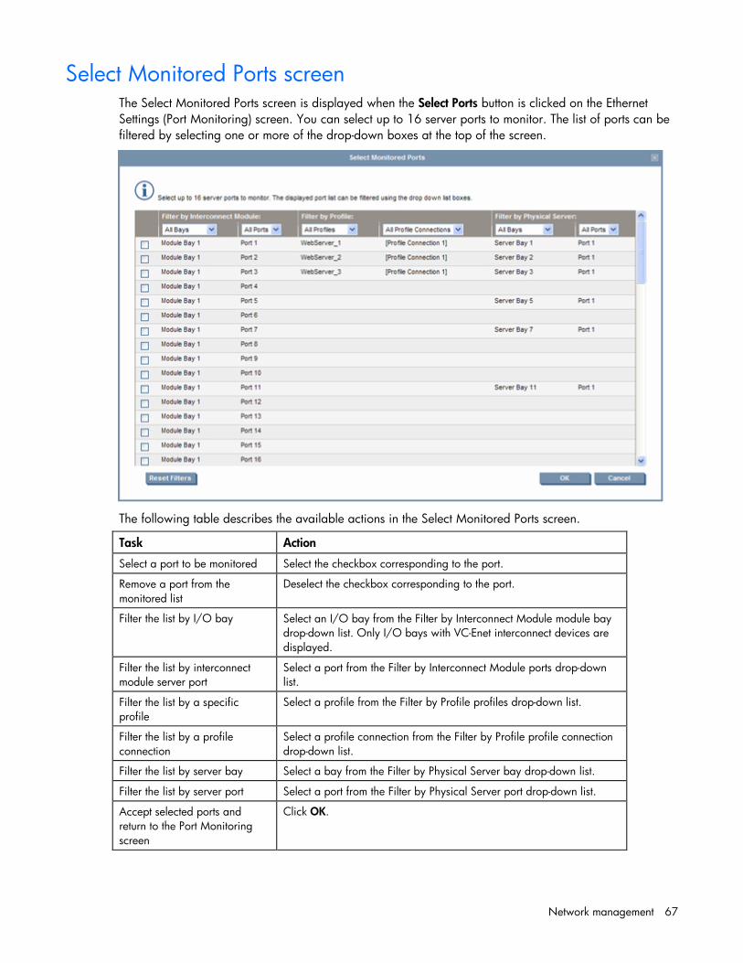
Network management 67
Select Monitored Ports screen The Select Monitored Ports screen is displayed when the Select Ports button is clicked on the Ethernet Settings (Port Monitoring) screen. You can select up to 16 server ports to monitor. The list of ports can be filtered by selecting one or more of the drop-down boxes at the top of the screen.
The following table describes the available actions in the Select Monitored Ports screen.
Task Action
Select a port to be monitored Select the checkbox corresponding to the port.
Remove a port from the monitored list
Deselect the checkbox corresponding to the port.
Filter the list by I/O bay Select an I/O bay from the Filter by Interconnect Module module bay drop-down list. Only I/O bays with VC-Enet interconnect devices are displayed.
Filter the list by interconnect module server port
Select a port from the Filter by Interconnect Module ports drop-down list.
Filter the list by a specific profile
Select a profile from the Filter by Profile profiles drop-down list.
Filter the list by a profile connection
Select a profile connection from the Filter by Profile profile connection drop-down list.
Filter the list by server bay Select a bay from the Filter by Physical Server bay drop-down list.
Filter the list by server port Select a port from the Filter by Physical Server port drop-down list.
Accept selected ports and return to the Port Monitoring screen
Click OK.

Network management 68
Task Action
Clear newly selected ports without saving and return to the Port Monitoring screen
Click Cancel.
Ethernet Settings (Advanced Settings) screen Use this screen to perform the following tasks:
• Set Server VLAN Tagging Support (on page 69)
• Use the Multiple Networks Link Speed Settings (on page 72) to set a custom value for preferred link connection speed or maximum link connection speed
• Enable or disable MAC Cache Failover
• Modify the refresh interval for MAC Cache Failover (on page 72)
• Enable or disable IGMP Snooping (on page 72)
• Modify the idle timeout interval for IGMP Snooping
Only users with network administrator privileges can change this screen.

Network management 69
Server VLAN Tagging Support This option provides explicit VLAN tagging support for server links, enabling each server link to be shared among multiple networks. Users can map server VLAN-tagged Ethernet packets to specific networks, which is essential in deploying server virtualization applications such as a virtual operating system solution.

Network management 70
The following figure shows tunneled VLAN tags. On the dedicated, green network, both uplink and server VLAN tags are tunneled through Virtual Connect unchanged. On the shared, red and blue networks, uplink VLAN tags are mapped to networks. Untagged frames are mapped to the native VLAN, if present, otherwise they are dropped. Server frames are untagged only, and tagged frames are dropped. Each server port is connected to a single network.
The following figure shows mapped VLAN tags, a feature that enables users to define how each server VLAN tag is mapped to a specific network. Each server port can connect to multiple networks. Server NIC1 is connected to both the Green and Red networks. Server NIC2 is connected to the Red network, and Server NIC3 is connected to the Red, Blue, and Orange networks. All server NICs can send and received tagged or untagged traffic.
If Virtual Connect is set to map VLAN tags, VC-Enet modules accept incoming frames with valid server VLAN tags and translate server-assigned VLANs into corresponding internal network VLANs, thus placing the server packet on the correct network. When these frames reach the uplinks, network VLANs are once again translated into external data center VLANs. Similarly, VLANs are translated back to server-assigned VLANs (or stripped and untagged) before sending frames out to servers. This function allows for the

Network management 71
possibility of configurations where server VLANs might not match external VLANs used on uplinks. To avoid this scenario, you can select the 'Force server connections to use the same VLAN mappings as shared uplink sets' option.
Server port connections to networks are defined on the Define Server Profile screen (on page 100).
Restrictions and limitations • Maximum number of networks per shared uplink set:
o For Virtual Connect v2.30 and later – 128 networks
o For Virtual Connect v1.34 and Virtual Connect v2.10 – 64 networks
o For all other versions of Virtual Connect – 32 networks
• As of Virtual Connect Firmware v2.30, the following shared uplink set rules apply per domain when in mapping mode:
o Maximum of 28 unique server mapped VLANs per server profile network connection
o Maximum of 128 unique VLANs per shared uplink set
o Maximum of 320 unique VLANs per Virtual Connect Ethernet module
o Every VLAN on every uplink counts towards the 320 VLAN limit. If a shared uplink set is comprised of multiple uplinks, each VLAN on that shared uplink set is counted multiple times.
o Although 320 VLANs can be supported within each module, the overall number of VLANs within the VC Domain is also restricted due to performance limitations of the VC Manager during module restore or recovery. The limits are defined based on usage scenarios.
• You can either select to tunnel VLAN tags or map VLAN tags on a domain, but not both. The option is grayed out if it is not supported by the configuration.
• The port VLAN ID must be selected from a specific shared uplink set.
• When the 'Tunnel VLAN Tags' option is selected on the Ethernet Settings (Advanced Settings) screen (on page 68) or the 'Enable VLAN Tunneling' option is selected on the Define Ethernet Network screen (on page 54), server VLAN tagging is supported only on networks with dedicated uplinks and cannot be used with shared uplink sets.
• If the 'Tunnel VLAN Tags' option is selected and VLAN tunneling is enabled on any dedicated network, the 'Map VLAN Tags' option cannot be selected. VLAN tunneling must be disabled on all dedicated networks before the 'Map VLAN Tags' option can be selected. Before Virtual Connect v1.31, all networks had tunneling enabled. If you upgrade from a previous version, you cannot enable mapping of VLANs unless you disable tunneling on each network from the Edit Ethernet Network screen (on page 57).
TIP: Use CLI scripting to automate the disabling of VLAN tunneling on multiple dedicated vNets. For information on CLI scripting, see the HP BladeSystem Virtual Connect Command Line Interface User Guide.
• If the 'Map VLAN Tags' option is selected and any server port is connected to multiple networks, the 'Tunnel VLAN Tags' option cannot be selected. All server profile connections assigned to multiple networks must be assigned to a single network (or 'Unassigned') before the 'Tunnel VLAN Tags' option can be selected.
• The 'Force server connections to use the same VLAN mappings as shared uplink sets' checkbox can be selected under the following conditions:
o The 'Map VLAN Tags' option is selected.

Network management 72
o No server profile connections are assigned to multiple networks not linked to a Shared Uplink Set.
This action forces all server connections mapped to multiple networks to be linked to a shared uplink set. Server administrators cannot override this selection when creating or editing a profile.
Multiple Networks Link Speed Settings When using mapped VLAN tags (multiple networks over a single link), these settings are used for the overall link speed control. Select the checkbox next to each item to set the value.
These settings affect only newly created profiles. Changing these settings does not affect any assigned profiles.
To set the speed, click the selection box, select a setting (100Mb to 10Gb), and then click OK.
• Set a Custom value for the Preferred Link Connection Speed.
This value is the default speed for server profile connections mapped to this network. The server administrator can override this setting on an individual profile connection.
• Set a Custom value for the Maximum Link Connection Speed.
This value is the maximum speed for server profile connections mapped to this network. The server administrator can override this setting on an individual profile connection.
Virtual Connect can only control link speed for Flex-10 NICs when they are connected to an HP Virtual Connect Flex-10 Module. Virtual Connect cannot control the link speed of traditional NICs. For additional information, see "Flex-10 overview (on page 94)."
MAC Cache Failover When a VC-Enet uplink that was previously in standby mode becomes active, it can take several minutes for external Ethernet switches to recognize that the c-Class server blades can now be reached on this newly-active connection. Enabling Fast MAC Cache Failover causes Virtual Connect to transmit Ethernet packets on newly-active links, which enables the external Ethernet switches to identify the new connection (and update their MAC caches appropriately). This transmission sequence repeats a few times at the MAC refresh interval (5 seconds recommended) and completes in about 1 minute.
IMPORTANT: Be sure to set switches to allow MAC addresses to move from one port to another without waiting for an expiration period or causing a lock out.
IGMP Snooping The IGMP Snooping feature allows VC-Enet modules to monitor (snoop) the IGMP IP multicast membership activities and configure hardware Layer 2 switching behavior of multicast traffic to optimize network resource usage. Currently only IGMP v1 and v2 (RFC2236) are supported.
The IGMP Snooping idle timeout interval is set to 260 seconds by default. This value is the "Group Membership Interval" value as specified by IGMP v2 specification (RFC2236). For optimum network resource usage, set the interval to match the configuration on the customer network's multicast router settings.

Network management 73
Stacking Links screen To access this screen, click the Stacking Links link under Fibre Channel Settings in the left VC Manager navigation window.
Be sure to connect any Ethernet module stacking cables before running the network setup wizard.
IMPORTANT: For a Virtual Connect environment to operate properly, all Virtual Connect Ethernet modules within the Virtual Connect domain must be interconnected with stacking links. HP strongly recommends that redundancy be maintained in stacking links to ensure continued connectivity of servers to the external networks.
This screen enables the user to determine whether all stacking cables are properly installed so that all Virtual Connect Ethernet modules within the domain are interconnected:
• Connection Status indicates whether all of the Virtual Connect Ethernet modules within the domain are interconnected with stacking cables and accessible. Lack of connection status to all Virtual Connect Ethernet modules results in a critical alert.
o OK indicates that all modules are connected.
o Failed indicates that one or more modules are not connected properly. Check the cable connections.
• Redundancy Status indicates whether all Virtual Connect Ethernet modules would remain fully interconnected if a module or external cable was removed or failed. Horizontally-adjacent modules are considered to have OK redundancy status because of the reliability of their internal link.
o OK indicates that redundant/reliable connections exist.
o Degraded indicates that additional stacking cables should be connected to provide full redundancy.
The table on this screen lists all of the Ethernet stacking links found within the Virtual Connect domain. Each row of the table identifies the link speed and the connections on both sides of the link, identified by the module and port number.
Network management 74
Port X0 indicates the 10Gb port connected through the midplane of horizontally-adjacent VC-Enet modules.
Ports X7 and X8 connect to the internal link between horizontally-adjacent Flex-10 enabled VC-Enet modules.
NOTE: Virtual Connect does not support stacking for FC modules, so each VC-FC module requires uplink connections to the external FC SAN environment.
For more information on connecting stacking links, and stacking links in a multi-enclosure environment, see the HP Virtual Connect for c-Class BladeSystem Setup and Installation Guide.
Shared uplink sets and VLAN tagging A shared uplink set is a way of identifying Virtual Connect Ethernet module uplinks that will carry multiple networks over the same cable. In this case, each Ethernet packet carries a VLAN tag (IEEE 802.1Q) to identify the specific network to which it belongs. On shared uplinks, the VLAN tags are added when packets leave the VC-enabled enclosure and are removed when packets enter the enclosure. The external Ethernet switch and the Virtual Connect Manager must be configured to use the same VLAN tag identifier (a number between 1 and 4094) for each network on the shared uplink(s).
Virtual Connect places no special restrictions on which VLAN identifiers can be used, so the VLAN IDs already used for the networks in the data center can be used on these shared uplinks. To configure a shared uplink set for VLAN tagging, obtain a list of the network names and their VLAN IDs.
A shared uplink set enables multiple ports to be included to support port aggregation and link failover with a consistent set of VLAN tags.
Because VLAN tags are added or removed when Ethernet packets leave or enter the VC-Enet shared uplink, the VLAN tags have no relevance after the Ethernet packet enters the enclosure.
IMPORTANT: If you are deploying a server where VLAN tags will be used (added) on the server itself, do not connect the server Ethernet port carrying VLAN-tagged traffic to a shared uplink set.
Identifying an associated network as the native VLAN causes all untagged incoming Ethernet packets to be placed onto this network. Only one associated network can be designated as the native VLAN. All out-going Ethernet packets are VLAN tagged.
To enable native VLAN when defining a shared uplink set, select the box under Native. To enable or disable native VLAN on an existing network, go to the Edit a Shared Uplink Set screen ("Edit Shared Uplink Set screen" on page 77). Click on the edit icon, and then select or deselect the box under Native.
Define Shared Uplink Set screen To access this screen, click the Shared Uplink Sets link in the left VC Manager navigation window, and then click Define Uplink Set, or select Define Uplink Set from the Define pull-down menu.
The Define Shared Uplink Set screen is accessible to all users with network privileges by clicking the Define a Shared Uplink link from the VC Manager home page or from the Define pull-down menu.

Network management 75
For Virtual Connect v1.34 and Virtual Connect v2.10, a maximum of 64 associated networks is supported in each shared uplink set. All other versions support a maximum of 32 networks per shared uplink set.
The following table describes the fields within the Define Shared Uplink Set screen.
Field name Description
Ethernet Shared External Uplink Set
Uplink Set Name Descriptive name for the shared uplink set. Do not use spaces.
External Uplink Ports
Port Enclosure, bay, and port number
Port Role Displays whether the port is designated as primary or secondary
Port Status Displays linked or unlinked
Connector type The type of connector on the port; for example, RJ-45
Connected to If the individual port is connected to a switch that supports LLDP, the switch MAC address and switch port number appear. A link is provided to obtain more information about the far-end switch port.
PID PID status icon (illuminated or not illuminated) for the port
Speed/Duplex Pull-down menu to specify the speed and duplex (where applicable) of the uplink port
Associated Networks (VLAN-tagged)

Network management 76
Field name Description
Network Name Displays the name of the associated networks
VLAN ID Displays the VLAN ID number
Native Select whether native VLAN is enabled (checked) or disabled (unchecked).
Smart Link Select whether Smart Link is enabled (checked) or disabled (unchecked).
Private Network Select to designate (checked) or not to designate (unchecked) this network as a private network.
The following table describes the available actions in the Define Shared Uplink Set screen. Clicking another link in the pull-down menu or left navigation window causes current edits that have not been applied to be lost.
Task Action
Add an external port Click the down arrow on Add Port. Select the enclosure, bay number, and port number.
Set the Port Role to primary or secondary
Click the down arrow in the Port Role column and select Primary or Secondary.
Change the uplink interface port speed or disable the port
Click the drop-down box under Speed/Duplex, and then select a setting.
Delete a port Click the Delete icon in the Delete column of the port to be deleted.
Change connection mode Click the down arrow in the box next to Connection Mode, and then select Auto or Failover. For information on Connection Modes, see "Defining a shared uplink set (on page 76)."
Add an Associated Network Right-click on the header row of the Associated Networks (VLAN tagged) table to display a menu, and then select Add.
Enable native VLAN on the network being defined
Select the Native checkbox. Only one network can be designated as the native VLAN.
Enable or disable Smart Link on the network being defined
Select the Smart Link checkbox.
Designate or do not designate this network as a private network
Select the Private Network checkbox.
Set a custom value for preferred link connection speed or maximum link connection speed
Select the Advanced Network Settings checkbox.
Edit associated network properties
Left-click to select an associated network, right-click to display a menu, and then select Edit.
Delete an associated network Left-click to select an associated network, right-click to display a menu, and then select Delete.
Defining a shared uplink set To define a shared uplink set:

Network management 77
1. Enter the shared uplink set name. The uplink set name can be up to 64 characters in length (no spaces).
2. Add one or more external ports using the Add Port pull-down menu. Only available ports are listed, and they display the current port link status. Select two or more ports to ensure a high availability connection.
3. Select the speed and duplex (where applicable) of the uplink ports. Click the drop-down box under Speed/Duplex, and then select a setting. Half-duplex operation is not supported by the Virtual Connect Ethernet module.
IMPORTANT: Be sure that the uplink interface port speed matches the speed set on the corresponding network switch port. If using autonegotiation, both ports must be configured to use autonegotiation or they might not link.
4. Select the Connection Mode:
o Auto (recommended)—This mode enables the uplinks to attempt to form aggregation groups using IEEE 802.3ad link aggregation control protocol, and to select the highest performing uplink as the active path to external networks.
Aggregation groups require multiple ports from a single Virtual Connect Ethernet module to be connected to a single external switch that supports automatic formation of LACP aggregation groups. Multiple aggregation groups may be formed from the ports selected for the network. The highest performing aggregation group is selected as active, with other aggregation groups and individual links used as standby connections.
o Failover—If this mode is selected, set the port to Primary or Secondary. Only a single link is used as the active link to the external networks with other ports used as standby connections.
5. Identify the Associated Networks that will use this shared uplink:
a. Right-click the header row in the Associated Networks table to display a menu, and then select Add.
b. Enter the name of the network.
c. Enter the number for the VLAN ID (1 to 4094) for that network as defined by the network administrator and as configured on the external Ethernet switch.
d. Select whether to enable (checked) or disable (unchecked) native VLAN. Only one network can be selected as the native VLAN. See "Shared uplink sets and VLAN tagging (on page 74)."
e. Select whether to enable (checked) or disable (unchecked) Smart Link (on page 53).
f. Select whether to designate (checked) or not designate (unchecked) the network as a private network ("Private Networks" on page 53).
g. Repeat steps a through f for all networks to use the shared uplink set.
6. Click Apply. The shared uplink and associated networks are now defined and available for use in creating server profiles.
Edit Shared Uplink Set screen To access this screen, click the shared uplink set to be edited in the left VC Manager navigation window.

Network management 78
Use this screen to edit the properties of an existing shared uplink set, add/delete an associated network, or delete a shared uplink set. This screen has the same fields as the Define Shared Uplink screen. The screen can be edited only by users with network privileges, but it is viewable by all authorized users.
The following table describes the fields within the Edit Shared Uplink Set screen.
Field name Description
Ethernet Shared External Uplink Set
Uplink Set Name Descriptive name for the shared uplink set. Do not use spaces.
External Uplink Ports
Port Enclosure, bay, and port number
Port Role Displays whether the port is designated as primary or secondary
Port Status Displays linked or unlinked
Connector type The type of connector on the port; for example, RJ-45
Connected to If the individual port is connected to a switch that supports LLDP, the switch MAC address and switch port number appear. A link is provided to obtain more information about the far-end switch port.
PID PID status icon (illuminated or not illuminated) for the port
Speed/Duplex Pull-down menu to specify the speed and duplex (where applicable) of the uplink port. Half-duplex operations are not supported by the VC-Enet module.
Associated Networks (VLAN-tagged)
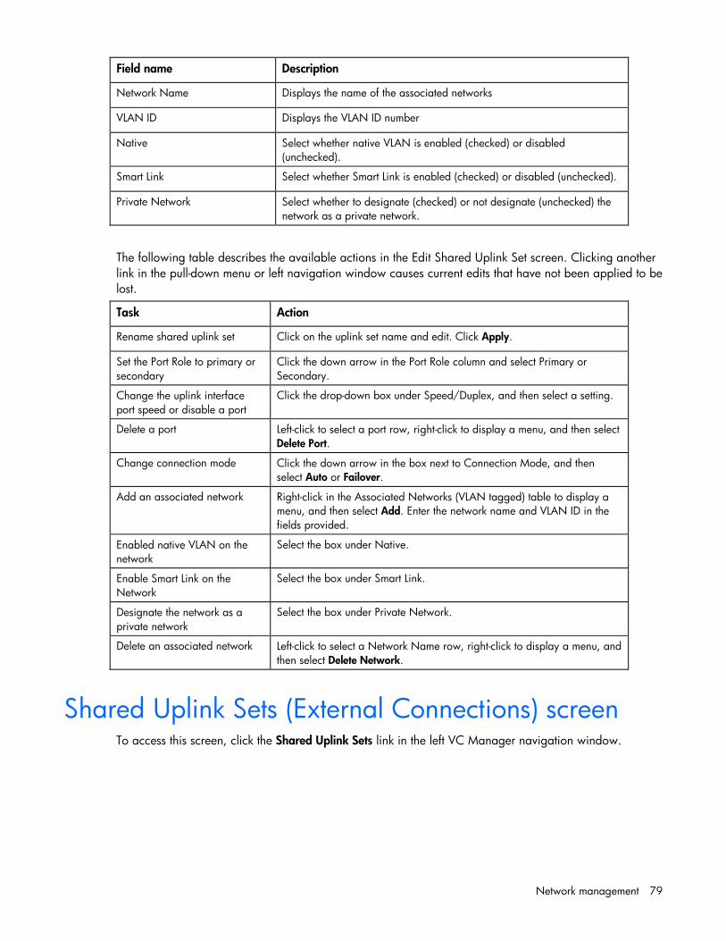
Network management 79
Field name Description
Network Name Displays the name of the associated networks
VLAN ID Displays the VLAN ID number
Native Select whether native VLAN is enabled (checked) or disabled (unchecked).
Smart Link Select whether Smart Link is enabled (checked) or disabled (unchecked).
Private Network Select whether to designate (checked) or not designate (unchecked) the network as a private network.
The following table describes the available actions in the Edit Shared Uplink Set screen. Clicking another link in the pull-down menu or left navigation window causes current edits that have not been applied to be lost.
Task Action
Rename shared uplink set Click on the uplink set name and edit. Click Apply.
Set the Port Role to primary or secondary
Click the down arrow in the Port Role column and select Primary or Secondary.
Change the uplink interface port speed or disable a port
Click the drop-down box under Speed/Duplex, and then select a setting.
Delete a port Left-click to select a port row, right-click to display a menu, and then select Delete Port.
Change connection mode Click the down arrow in the box next to Connection Mode, and then select Auto or Failover.
Add an associated network Right-click in the Associated Networks (VLAN tagged) table to display a menu, and then select Add. Enter the network name and VLAN ID in the fields provided.
Enabled native VLAN on the network
Select the box under Native.
Enable Smart Link on the Network
Select the box under Smart Link.
Designate the network as a private network
Select the box under Private Network.
Delete an associated network Left-click to select a Network Name row, right-click to display a menu, and then select Delete Network.
Shared Uplink Sets (External Connections) screen To access this screen, click the Shared Uplink Sets link in the left VC Manager navigation window.

Network management 80
This summary screen provides an overview of external shared uplink connections. This screen is only applicable if multiple networks are being connected over a single external uplink set by the use of VLAN tagging.
The following table describes the fields within the Shared Uplink Sets screen.
Field Description
Shared Uplink Set Displays the status, UID, and name of the shared uplink set
Port Status Status of the uplink port, linked or unlinked
Connector Type The type of connector on the port; for example, SFP-SX
Uplink Port Enclosure, bay, and port number of the external uplink
To add a shared uplink set, right-click on the header row to display a menu, and then select Add.
To edit a shared uplink set, left-click to select an uplink set, right-click to display a menu, and then select Edit.
To delete a shared uplink set, left-click to select an uplink set, right-click to display a menu, and then select Delete.

Network management 81
Shared Uplink Sets (Associated Networks) screen To access this screen, click the Shared Uplink Sets link in the left VC Manager navigation window, and then click the Associated Networks tab.
This summary screen displays the mapping of networks to external shared uplink connections. This screen is only applicable if multiple networks are being connected over a single external uplink set by the use of VLAN tagging.

Storage management 82
Storage management
Storage overview The Virtual Connect Fibre Channel modules enable the c-Class administrator to reduce FC cabling by making use of N_Port_ID virtualization (NPIV). The HP VC-FC acts as an HBA aggregator where each NPIV-enabled N-port uplink can carry the FC traffic for multiple HBAs.
Because it uses an N-port uplink, it can be connected to data center Brocade, McData, Cisco, and Qlogic FC switches that support the NPIV protocol. When the server blade HBAs log in to the fabric through the VC-FC module, the HBA WWN is visible to the FC switch name server and can be managed as if it was connected directly.
IMPORTANT: The HP Virtual Connect Fibre Channel modules must be connected to a data center Fibre Channel switch that supports N_Port_ID virtualization (NPIV). See the switch firmware documentation for information to determine whether a specific switch supports NPIV and for instructions on enabling this support.
The VC-FC module has either four or eight uplinks. Each uplink is completely independent of the other uplinks and has a capability of aggregating up to 16 physical server HBA N-port links into an N-port uplink through the use of NPIV.
In previous versions of Virtual Connect, a one-to-one relationship existed between VC-FC uplinks and external FC SAN fabrics. Beginning with version 1.31 of Virtual Connect Manager, users can group multiple VC-FC module uplinks logically into a Virtual Connect fabric when attached to the same Fibre Channel SAN fabric. Using this feature, users can access more than one FC SAN fabric in their data center, plus have a flexible and fully redundant way to connect server blades to Fibre Channel SANs. User can connect to up to four SAN fabrics from one VC-FC module, and up to eight SAN fabrics from one HP VC 8Gb 24-Port module.
Virtual Connect Fabric By default, all of the VC-FC uplinks are grouped into a single fabric, distributing connectivity from all 16 server blades in the enclosure. If a port in the group becomes unavailable, hosts logged in through that port are reconnected to the fabric through the remaining ports in the group, resulting in auto-failover. However, users can redistribute the connections manually.
To form a Virtual Connect fabric correctly, participating uplinks must be connected to the same SAN fabric. The WWN of the principle fabric switch indicates connectivity to the same SAN fabric in Virtual Connect.
The module uses dynamic login distribution to provide an uplink port path failover that allows server connections to failover within the Virtual Connect fabric. Server connections are redistributed across all available (currently logged into the external SAN) uplink ports.

Storage management 83
Define SAN Fabric screen To define a SAN fabric, select the Define SAN Fabric link on the Home page, or click Define SAN Fabric on the SAN Fabrics screen.
Only connect HP VC 4Gb FC module, HP VC 8Gb 24-Port FC module, or HP VC 8Gb 20-Port FC module uplinks to Fibre Channel switch ports that are NPIV-enabled. If using a Brocade FC switch, verify that NPIV is enabled properly by using the portshow command. If NPIV is not enabled properly, you might need to downgrade the Brocade switch firmware, and then upgrade the firmware again.
• Single enclosure domain

Storage management 84
• Multi-enclosure domain
The following table describes the columns and fields within the Define SAN Fabric screen.
Column Description
Fabric Name Descriptive name for the virtual fabric. Do not use spaces.
Login Re-Distribution Login Re-distribution setting for the fabric
Configured Speed Speed of the uplink ports, available after a port has been added
Uplink Port Number of the enclosure uplink port
Bay Enclosure bay selected for the SAN fabric. Only uplinks on the same bay can be in the same SAN fabric.
Port Status Status of the uplink port
Speed Port speed for the uplink ports in the fabric
Connected To WWN of the principal switch on the SAN fabric that this port is connected to on the other end
The following table describes the available actions in the Define SAN Fabric screen. Clicking another link in the pull-down menu or left navigation window causes the current edits that have not been applied to be lost.
Task Description
Create a fabric name Type a name in the Fabric Name field. Do not use spaces.
Add an uplink port Click Add Port.

Storage management 85
Task Description
Set the uplink port speed After an uplink port has been added, click the drop-down arrow in the Configured Speed field, and then select a speed.
Delete an uplink port Left-click an uplink port row to select it, right-click to display a menu, and then select Delete Port.
Save changes and remain on this screen
Click Apply.
Clear the current, unsaved changes and return to the home page
Click Cancel.
Enabling NPIV on the fabric switch When installing the VC-FC module, NPIV must be enabled on the fabric switch that is attached to the VC-FC module uplinks before the server blade HBAs can log in to the fabric. See the Fibre Channel switch firmware documentation for information on whether it supports NPIV and for instructions on enabling this support.
Brocade switch Most Brocade Fibre Channel switches running Fabric OS 5.1.0 or later will support NPIV. All Brocade 4Gb- and 8Gb-capable Fibre Channel switches are configured with NPIV enabled by default.
When not enabled by default, use the portCfgNPIVPort command within the Brocade switch command line interface to enable NPIV. For additional information on usage of the portCfgNPIVPort command, see the Brocade switch firmware documentation.
To enable NPIV on all other Brocade Fibre Channel Switches, use the following Fabric OS CLI procedure:
1. To enable or disable NPIV on a port-by-port basis, use the portCfgNPIVPort command.
Example: To enable NPIV on port 10, enter following command: switch:admin> portCfgNPIVPort 10, 1
2. To specify the number of virtual N_Port_IDs per port or per switch, use the configure command with either of the following parameters:
switch.login.perPortMax—Use this parameter to set the number of virtual N_Port_IDs per port to a value between 0 and 255. The default setting is 126.
switch.login.perSwitchMax—Use this parameter to set the number of virtual N_Port_IDs per switch to a value between 0 and (126 * number of ports). The default setting is (15 * number of ports).
Example: switch:admin> switchdisable switch:admin> configure Configure... Fabric parameters (yes, y, no, n): [no] Virtual Channel parameters (yes, y, no, n): [no] F-Port login parameters (yes, y, no, n): [no] y Maximum logins per switch: (1..4032) [4032] 2048

Storage management 86
Maximum logins per port: (1..255) [255] 126 . . switch:admin> switchenable
Cisco switch Cisco Fibre Channel switches running SAN-OS 3.0 or later will support NPIV. To enable NPIV on Cisco Fibre Channel Switches running the Cisco Device Manager, use the following procedure:
1. From the Cisco Device Manager, click Admin, and then select FeatureControl. The Feature Control window appears.
2. Click the row titled NPIV.
3. In the Action column select enable, and then click Apply.
4. Click Close to return to the Name Server screen.
5. Click Refresh to display the Host ports.
McDATA switch McDATA Fibre Channel switches with E/OS 8.0 or later will support NPIV. McDATA switches require an optional license to enable this function. Use the following procedure to apply this license and enable NPIV:
1. From a browser, open the web user interface for the McDATA switch that is to be connected to the VC-FC module. The Node List view details the devices attached to the McDATA switch.
2. To install the NPIV license, click Maintenance, and then select Options Features.
3. Enter the license key for NPIV in the Feature Key field. Select the key as the "N_Port ID Virtualization (NPIV)." Link from the window and apply the key by clicking OK. A check mark in the left window indicates that the N_Port ID Virtualization key is installed.
4. Click Configure, and then select Ports>NPIV.
5. Click Enable.
6. At the prompt click OK if you are sure you want to enable NPIV.
7. In the Login column, set the value to 17 or higher for each port connected to the VC-FC to ensure proper operation.
8. Click OK to save changes.
HP StorageWorks 8/20q Fibre Channel Switch The HP StorageWorks 8/20q Fiber Channel Switch supports NPIV by default. No additional configuration is required.

Storage management 87
SAN Fabrics (External Connections) To access this screen, click SAN Fabrics in the left VC Manager navigation window.
This screen lists all of the SAN fabrics that have been created and displays the external connection information.
• To edit a fabric, left-click to select the SAN Fabric row, right-click to display a menu, and then select Edit.
• To add a fabric, left-click to select the SAN Fabric row, right-click to display a menu, and then select Add.
• To delete a fabric, left-click to select the SAN Fabric row, right-click to display a menu, and then select Delete.
• To redistribute logins on a SAN fabric, left-click to select the SAN Fabric row, right-click to display a menu, and then select Redistribute Logins.
SAN Fabrics (Server Connections) To access this screen, click SAN Fabrics in the left VC Manager navigation window, and then click the Server Connections tab.
This screen lists all of the SAN fabrics that have been created and displays the server connection information.

Storage management 88
To delete a fabric, select the checkbox of that line item, and then click Delete.
To create a new fabric, click Define SAN Fabric.
To redistribute logins on a SAN fabric, click Redistribute Logins.

Storage management 89
Edit SAN Fabric Use this screen to edit a SAN fabric configuration.
The following table describes the fields within the Edit SAN Fabric screen.
Field Description
Fabric Name Descriptive name for the fabric. Do not use spaces.
Status Status of the fabric
Login Re-distribution Type of login re-distribution assigned to the fabric (manual or automatic)
Configured Speed Requested speed of the uplink port
Uplink Port Faceplate name of the port
Bay Enclosure bay selected for the SAN fabric
Port Status Status of the uplink port
Speed Actual, connected speed of the uplink port
Connected To WWN of the principal switch on the SAN fabric that this port is connected to on the other end

Storage management 90
The following table describes the available actions in the Edit SAN Fabric screen. Clicking another link in the pull-down menu or left navigation window causes the current edits that have not been applied to be lost.
Task Description
Modify a fabric name Type a name in the Fabric Name field. Do not use spaces.
Set the uplink port speed Click the drop-down arrow in the Configured Speed field and select a speed.
Add an uplink port Click Add Port.
Delete an uplink port Left-click and uplink port row to select it, right-click to display a menu, and then select Delete Port.
Save changes and remain on this screen
Click Apply.
Clear the current, unsaved changes and return to the home page
Click Cancel.
Fibre Channel Settings (WWN Settings) screen Use this screen to assign World Wide Names.
Each server blade FC HBA mezzanine card ships with factory default port and node WWNs for each FC HBA port. Each WWN is a 64-bit number that uniquely identifies the FC HBA port/node to other devices on the network. While the hardware ships with default WWNs, Virtual Connect has the ability to assign WWNs that will override the factory default WWNs while the server remains in that Virtual Connect enclosure. When configured to assign WWNs, Virtual Connect securely manages the WWNs by accessing the physical FC HBA through the enclosure Onboard Administrator and the iLO interfaces on the individual server blades.
When assigning WWNs to a FC HBA port, Virtual Connect will assign both a port WWN and a node WWN. Because the port WWN is typically used for configuring fabric zoning, it is the WWN displayed throughout the Virtual Connect user interface. The assigned node WWN is always the same as the port WWN incremented by one.
Virtual Connect assigns or migrates WWNs for server FC ports connected to HP Virtual Connect modules. Virtual Connect also assigns WWNs to FC ports that are not connected to an I/O module because Virtual Connect modules can be added later. Server FC ports connected to non-Virtual Connect modules retain the server factory default WWNs.
Configuring Virtual Connect to assign WWNs in server blades maintains a consistent storage identity (WWN) even when the underlying server hardware is changed. This method allows server blades to be replaced without affecting the external Fibre Channel SAN administration.
CAUTION: To avoid storage networking issues and potential loss of data associated with duplicate WWNs on a FC SAN fabric, plan carefully when allowing Virtual Connect to assign server blade WWNs so that the configured range of WWNs is used only once within the environment.
There are two ways to access this screen:
• Click WWN Settings under Fibre Channel Settings in the left window of the homepage.

Storage management 91
• Select Fibre Channel Settings from the Configure pull-down menu.

Server management 92
Server management
Server profile overview A Virtual Connect server profile is a logical grouping of attributes related to server connectivity that can be assigned to a server blade. The server profile can include MAC address, PXE, and network connection settings for each server NIC port and WWN, SAN fabric connection, and SAN boot parameter settings for each Fibre Channel HBA port. After being defined, the server profile can be assigned to any server blade within the Virtual Connect domain. A Virtual Connect domain can have a maximum of 64 Virtual Connect server profiles.
Virtual Connect provides the ability to configure PXE settings when using either VC Assigned or factory default MAC addresses. In addition, Use BIOS is an option for PXE, which maintains the current settings as configured by RBSU.
Virtual Connect also provides the ability to override the Virtual Connect assigned MACs and/or WWNs when creating a new profile. See "Define Server Profile Screen (on page 100)."
When a server profile is assigned to a server blade, the Virtual Connect Manager securely connects to the server blade, configures the NIC ports with the appropriate MAC addresses and PXE settings, and configures the FC HBA ports with the appropriate WWNs and SAN boot settings. In addition, the Virtual Connect Manager automatically connects the server blade Ethernet and Fibre Channel ports to the specified networks and SAN fabrics. This server profile can then be re-assigned to another server blade as needed, while maintaining the server's network and SAN identity and connectivity.
The Virtual Connect Manager can be configured so that server blades use server factory default MACs/WWNs or Virtual-Connect-administered MACs/WWNs. These administered values override the default MAC addresses and WWNs when a server profile is assigned to a server, and appear to pre-boot environments and host operating system software as the hardware addresses. To use administered MAC addresses, select a range of HP pre-defined or user-specified MAC addresses. See "MAC address settings (on page 63)."
IMPORTANT: Be sure to review the following list of guidelines before creating and deploying server profiles.
• The server blade firmware and option card firmware must be at a revision that supports Virtual Connect profile assignment. See the HP website (http://www.hp.com/go/bladesystemupdates).
• Before creating the first server profile, select whether to use moveable, administered MAC addresses and WWNs or whether to use the local server blade factory default MAC addresses and WWNs. See "MAC address settings (on page 63)" and "WWN settings (on page 103)."
• After an enclosure is imported into a Virtual Connect domain, server blades remain isolated from the networks and SAN fabrics until a server profile is created and assigned.
• Server blades must be powered off to receive (or relinquish) a server profile assignment when using Virtual Connect-administered MAC addresses, WWNs, or changing Fibre Channel boot parameters.
• FC SAN Connections are shown in server profile screens when only there is an HP Virtual Connect Fibre Channel Module in the enclosure managed by Virtual Connect. FC SAN Connections are added in pairs and cannot be deleted. If an HP Virtual Connect Fibre Channel Module is added to a

Server management 93
Virtual Connect domain that has existing profiles, an option to add FC connections appears in the existing profiles during editing.
• Some server profile SAN boot settings (controller boot order) are applied by Virtual Connect only after the server blade has been booted at least once with the final mezzanine card configuration.
• If PXE, controller boot order, or SAN boot settings are made outside of Virtual Connect (using RBSU or other configuration tools), Virtual Connect will restore the settings defined by the server profile after the server blade completes the next boot cycle.
• To boot properly from SAN when using Linux and VMware ESX 3.0.1 and ESX 3.0.2, change the QLogic QMH2462 4Gb FC HBA connection option to 'point-to-point only' in the QLogic BIOS configuration utility. The Emulex LPe 1105-HP 4Gb FC HBA does not require using the 'point-to-point' connection option to boot properly from SAN.
Server profiles are associated with a specific enclosure device bay. After a profile is assigned, the Virtual Connect Manager configures the server blade in that device bay with the appropriate MAC/PXE/WWN/SAN boot settings and connects the appropriate networks and fabrics. Server blades that have been assigned a profile and remain in the same device bay do not require further Virtual Connect Manager configuration during a server or enclosure power cycle. They will boot and gain access to the network and fabric when the server and interconnect modules are ready.
If a server blade is inserted into a device bay already assigned a server profile, Virtual Connect Manager automatically updates the configuration of that server blade before it is allowed to power up and connect to the network.
If a server blade is moved from a Virtual Connect managed enclosure to a non-Virtual Connect enclosure, local MAC addresses and WWNs are automatically returned to the original factory defaults. This feature prevents duplicate MAC addresses and WWNs from appearing in the data center because of a server blade redeployment.
NOTE: If you are using server factory default MAC addresses WWNs and default Fibre Channel boot parameters, you do not have to power off a server to make any profile changes. If you are using HP assigned or user assigned MAC addresses or WWNs, you must power a server off when moving a profile to the server or away from the server.
Multi-blade servers Certain HP Integrity server blades can be conjoined using a Scalable BladeLink (SBL) to create a single server. These servers are treated just like other server blades even though they are comprised of several physical server blades.
IMPORTANT: The term server blade, when applied to a multi-blade server, means the entire conjoined server, and not just a single server blade. For example, "a server profile is assigned to a server blade" means that a single server profile is assigned to an entire multi-blade server.
In each multi-blade server there is one blade that is identified as the monarch blade. The other blades are referred to as auxiliary blades. In most multi-blade servers the lowest numbered bay in the server is the monarch, but that is not always the case. Both the VCM CLI and GUI identify the monarch in the information provided about a multi-blade server. All communication to a multi-blade server, such as to the iLO user interface, is done through the monarch blade.
VCM displays multi-blade servers as a single entity showing the range of bays that comprise the server. For example, if a multi-blade server occupies bays 1, 2, 3 and 4, then VCM represents the server as

Server management 94
“Bays 1-4 (HP Integrity BL890c i2)”. This is true in the left navigation tree, in the Server Bays summary screen, in the list of bays that a profile can be assigned to in the Edit Server Profile screen, and so on.
A profile is assigned to an entire multi-blade server, not to the individual blades in the server. If a profile is assigned to an auxiliary blade (for example, a profile is assigned to an empty bay and then a multi-blade server is installed) that profile is ignored (in this case it’s the same as a profile assigned to a covered bay). In such a case VCM identifies the bay that the profile is assigned to as “Covered – Auxiliary”.
VCM maps the profile connection entries to ports on the blades in a multi-blade server as follows:
• Ethernet profile connection entries are evenly distributed across all of the blades in a multi-blade server. For example, if a multi-blade server is comprised of 4 blades then the 1st, 5th, 9th, etc Ethernet connections are assigned to the first blade, the 2nd, 6th, 10th etc Ethernet connections are assigned to the second blade, and so forth. The mapping of connection entries to specific ports on a blade are done the same way as for other full-height blades.
For more information, see "Port assignment (on page 97)."
• FC profile connection entries are mapped to blades such that all of the FC HBAs on the first blade are mapped first, then the HBAs on the second blade, and so on. When a profile is first created it will have enough FC profile connections for the HBAs on one blade. More FC connections can be added only after the profile has been assigned to a multi-blade server. The maximum number of FC connections allowed is N times the original number of entries where N is the number of blades in the multi-blade server that a profile is assigned to.
There are rare situations where VCM will not be able to retrieve information about all of the blades in multi-blade server (such as certain hardware failures that keep a blade from being in a normal state prior to applying power). In such cases VCM displays the Major error status icon. Where text is shown with the icon, the text is “Missing Data”. This is an indication of a serious problem with the multi-blade server that needs to be fixed. VCM cannot properly map profile connections to a server when it is in this state.
Multi-blade servers do not support iSCSI or FCoE.
Flex-10 overview Flex-10 technology is exclusive to Virtual Connect environments, and it allows Flex-10 enabled 10Gb NICs to enumerate as four FlexNICs per 10Gb port. These FlexNICs are actual PCIe functions, and they appear to the operating system or hypervisor as discrete NICs, each with its own driver instance.

Server management 95
Although these four FlexNICs share a single 10Gb physical interface, Virtual Connect is able to keep traffic for the FlexNICs isolated, and each FlexNIC is assigned to a different Virtual Connect network. Each FlexNIC can be assigned a different bandwidth (from 100Mb to 10Gb), which is enforced by hardware mechanisms.
A Flex-10 capable NIC (embedded Ethernet or mezzanine card) only enumerates as four FlexNICs per 10Gb port if that NIC is directly connected to an HP Virtual Connect Flex-10 Module or an empty interconnect bay. Eight FlexNICs are enumerated when connected to an empty interconnect bay because it is assumed that an HP Virtual Connect Flex-10 Module will be plugged into that bay. If a Flex-10 capable NIC is connected to a Virtual Connect interconnect module that does not support Flex-10 or a non-Virtual Connect interconnect module, that NIC enumerates as only one Ethernet device per physical port.
The following table shows an example of how a BL495c Flex-10 embedded Ethernet device would be enumerated when connected to different interconnects. For more information about mapping between servers and interconnect bays, see the HP c-Class enclosure documentation.
Connected to Number of NICs enumerated to the host
HP Virtual Connect Flex-10 Module 8
HP 1/10GB-F VC-Enet Module 2
HP GbE2c Ethernet Blade Switch 2
Cisco Catalyst Blade Switch 3120 2
Empty interconnect bay 8

Server management 96
Flex-10 configuration Network administrator
For each Virtual Connect network, the network administrator can set a "Preferred" and "Maximum" speed for FlexNICs that connect to that network. FlexNICs cannot connect to a network at a speed higher than the maximum speed set by the network administrator for that network. The "preferred" speed setting is the speed recommended by the network administrator for any FlexNIC that attaches to that network. The server administrator can choose to follow or disregard this recommendation.
The network administrator can change these two settings by clicking the Advanced button on the create/edit network screen. For additional information, see "Multiple Networks Link Speed Settings (on page 72)."
Server administrator
The server administrator can configure a requested bandwidth for every connection in a server profile. Virtual Connect can control the link speed of FlexNICs, but cannot control the link speed of traditional NICs.
The server administrator has three choices for Requested Bandwidth for each connection:
1. Preferred. Choosing "Preferred" sets the requested bandwidth equal to the bandwidth recommended by the network administrator's "Preferred" speed setting for that network. If the administrator has not configured a preferred bandwidth for the network, this setting is treated the same as "Auto".
2. Custom. Choosing "Custom" enables the user to specify a number between 100Mb and 10Gb (in increments of 100Mb) for requested bandwidth.
3. Auto. Choosing "Auto" evenly distributes the available bandwidth between all connections assigned to "auto".
For additional information, see "Bandwidth assignment (on page 98)."
Although the Port Speed Setting is available for all network connections in a profile, Virtual Connect can only control link speed for Flex-10 NICs when they are connected to an HP Virtual Connect Flex-10 Module. Virtual Connect cannot control the link speed of traditional NICs. Allowing specification of port speed regardless of the underlying NIC allows the profile to configure the connection automatically when moved to or from Flex-10 enabled servers and NICs.

Server management 97
The Allocated Bandwidth column displays "not allocated" until the profile is assigned to a device bay that contains a server. At that time, bandwidth is allocated to each connection and the result is reported in this column. See "Bandwidth assignment (on page 98)."
The Mapping column describes how each connection of a profile is assigned to physical devices in a server, and to which interconnect bay that device is connected. The four FlexNICs on port 1 of a server LOM that supports Flex-10 are numbered LOM:1-a, LOM:1-b, LOM:1-c, and LOM:1-d. If a LOM does not support Flex-10, then it is simply referenced by its port number (for example, LOM:1 or LOM:2).
Port assignment A server profile is simply a list of connections and other parameters until that profile is applied to a physical server. The same profile can be mapped to server hardware differently depending on the presence or absence of different mezzanine cards, and if Ethernet devices in the server are capable of supporting Flex-10.
In versions of firmware prior to VC 2.00 (versions that do not support Flex-10), server profile connections are assigned to a half-height server in the following order:
1. Assign a connection to LOM port 1.
2. Assign a connection to LOM port 2.
3. Assign a connection to MEZ1 port 1 (if present).
4. Assign a connection to MEZ1 port 2 (if present).
5. Assign a connection to MEZ2 port 1 (if present).
6. Assign a connection to MEZ2 port 2 (if present).
7. Assign a connection to MEZ2 port 3 (if present).
8. Assign a connection to MEZ2 port 4 (if present).
Connections are assigned to full-height servers in a similar way, but MEZ1 could have four ports and an additional mezzanine slot (MEZ3) exists.
Virtual Connect v2.00 and higher implements the same assignment algorithm with the exception that the algorithm repeats for all remaining unassigned profile connections. Additional profile connections can be assigned to Flex-10 capable devices with a maximum of four connections per Flex-10 capable port.
For example, a profile with eight connections is assigned to a half-height server with a Flex-10 LOM and a traditional NIC mezzanine in MEZ1 in the following order:
1. Assign profile connection 1 to LOM port 1.
2. Assign profile connection 2 to LOM port 2.
3. Assign profile connection 3 to MEZ1 port 1.
4. Assign profile connection 4 to MEZ1 port 2.
5. Assign profile connection 5 to LOM port 1 because it is Flex-10 capable and can support up to four connections.
6. Assign profile connection 6 to LOM port 2 because it is Flex-10 capable and can support up to four connections.
7. MEZ1 is not Flex-10 capable in this example, so additional connections cannot be assigned to MEZ1. Therefore, assign profile connection 7 to LOM port 1 because it is Flex-10 capable and can support up to four connections.

Server management 98
8. Assign profile connection 8 to LOM port 2 because it is Flex-10 capable and can support up to four connections.
For information about multi-blade server port assignments, see "Multi-blade servers (on page 93)."
Bandwidth assignment In Flex-10 environments, four FlexNICs must share a single 10Gb link. Each FlexNIC is allocated a portion of that 10Gb link's bandwidth. The bandwidth assigned to the four FlexNICs in a single physical port cannot exceed 10Gb, but the requested bandwidth settings specified by the user might exceed 10Gb.
Each FlexNIC is assigned a bandwidth value that is a portion of a 10Gb link. A 10Gb NIC might not be able to saturate a 10Gb link, so FlexNIC bandwidth is limited to a proportion of the NIC's actual throughput. For example, a FlexNIC that is assigned a requested bandwidth value of 5Gb might not be able to achieve a full 5Gb of throughput, but that FlexNIC is allocated half of the NIC's actual throughput.
Requested bandwidth is translated to assigned bandwidth with the following rules:
1. FlexNICs with a "preferred" or "custom" value for requested bandwidth receive their allocated bandwidth first. For example, if the requested bandwidth setting for the four FlexNICs on a given port are all 2Gb, then each FlexNIC can be assigned 2Gb of bandwidth.
Requested Allocated
FlexNIC a 2Gb 2Gb
FlexNIC b 2Gb 2Gb
FlexNIC c 2Gb 2Gb
FlexNIC d 2Gb 2Gb
2. After bandwidth is allocated in rule 1 above, FlexNICs with an "Auto" value for the requested bandwidth divide the remaining bandwidth evenly . For example, if the requested bandwidth setting for the four FlexNICs on a given port are 1Gb, Auto, Auto, and Auto, then the first FlexNIC is assigned 1Gb (as per rule 1) and the other three FlexNICs divide the remaining 9Gb evenly (3Gb each). There might be some cases where the bandwidth does not divide evenly as Virtual Connect assigns bandwidth in increments of 100Mb. Connections with a "preferred" setting to a network where no preferred speed has been defined are treated as a connection set to "auto".
Requested Allocated
FlexNIC a 1Gb 1Gb
FlexNIC b Auto 3Gb
FlexNIC c Auto 3Gb
FlexNIC d Auto 3Gb
In cases where the requested bandwidth settings specified by the user for the four FlexNICs in a single physical port exceed 10Gb, the following rules are applied in this order:
1. If FlexNICs with a "preferred" or "custom" value for requested bandwidth exceed 10Gb, each FlexNIC is allocated bandwidth proportional to its requested bandwidth setting. For example, if four FlexNICs on a given port have requested bandwidth settings of 1Gb, 2Gb, 4Gb, and 5Gb, their allocated bandwidth is as shown in the table below. In this example, 200Mb remains after dividing the 10Gb link. 100Mb is added to the two connections with the least bandwidth.

Server management 99
Requested Calculation Allocation + remainder
FlexNIC a 1Gb (1/12)*10Gb = 800Mb 900Mb
FlexNIC b 2Gb (2/12)*10Gb = 1600Mb 1700Mb
FlexNIC c 4Gb (4/12)*10Gb = 3300Mb 3300Mb
FlexNIC d 5Gb (5/12)*10Gb = 4100Mb 4100Mb
2. Every FlexNIC that is linked must be allocated at least 100Mb. For example, if four FlexNICs on a given port have requested bandwidth settings of 2Gb, 8Gb, Auto, and Auto, their allocated bandwidth is as shown in the table below. In this example, 100Mb must be allocated to the two FlexNICs set to "Auto" because no bandwidth would remain after allocating 2Gb and 8Gb to the first two FlexNICs. The two FlexNICs set for 2Gb and 8Gb requested bandwidth are allocated a proportion of the 9800Mb remaining after the two FlexNICs set to "Auto" receive 100Mb. In this example, there is a remainder of 100Mb, and that remainder is assigned to the FlexNIC whose allocated bandwidth differs the most from its requested bandwidth.
Requested Calculation Allocation + remainder
FlexNIC a 2Gb (2/10)*9800Mb = 1900Mb 2000Mb
FlexNIC b 8Gb (8/10)*9800Mb = 7800Mb 7800Mb
FlexNIC c Auto 100Mb 100Mb
FlexNIC d Auto 100Mb 100Mb
PXE settings Virtual Connect Manager v1.20 and higher supports three PXE options:
• Enable—VC Manager sends a configuration update to the mezzanine NIC or embedded NIC associated with the port to enable PXE operations.
• Disable—VC Manager sends a configuration update to the associated mezzanine NIC or embedded NIC to disable PXE operations.
• Use BIOS—Current BIOS settings are used for embedded NICs and mezzanine NIC PXE operations. VC Manager makes no changes to the current settings.
HP BladeSystem c-Class server blades have a factory default configuration for PXE to be enabled on embedded NIC 1 only and this is included as the last entry in the RBSU IPL priority list (boot order). VC Manager and the BIOS limit the number of PXE enabled embedded NICs to one. However, additional NIC ports from a mezzanine adapter can be enabled simultaneously using the "Use BIOS" settings.
All mezzanine NIC ports can be enabled for PXE booting at the same time, along with one embedded NIC port. If one or more mezzanine NIC ports are enabled for PXE booting, the user should review the RBSU IPL list to validate or update the boot order priority.
If you need to enable PXE on more than one NIC port, you must set all of the NICs' PXE configuration option in the VC Manager to "Use BIOS", and configure the individual PXE NIC settings using RBSU: F9 during POST to configure an embedded NIC, and F1 during POST to configure the mezzanine NIC ports. After all of the selected NIC ports are PXE enabled, you must configure the boot order using the RBSU boot order settings.

Server management 100
Only the first FlexNIC on each physical port of a Flex-10 device can be used for PXE boot. Virtual Connect cannot enable PXE boot on the remaining FlexNICs of a physical port.
Redundancy for PXE operations can be achieved using multiple PXE enabled NICs. However, the Virtual Connect Manager is limited to enabling only one NIC for PXE booting. If a configuration requires more than one NIC to have PXE enabled, you should set all NICs in the VC Manager to the "Use BIOS" setting, and configure the NIC PXE settings through their respective BIOS utilities (F9 for embedded NICs, and F1 for mezzanine NIC ports.)
The following table lists examples of valid configurations for PXE enabling NIC ports. This is only a sampling of the possible valid configurations.
PXE enabled PXE disabled Server blade configuration
Embedded NIC 1, Mezz 1 NIC port 1
Embedded NIC 2, Mezz NIC port 2
BL46xc with a dual-port NIC Mezzanine adapter
Embedded NIC 2, Mezz 1 NIC port 1
Embedded NIC 1, Mezz NIC port 2
BL46xc with a dual-port NIC Mezzanine adapter
Embedded NIC 1, Mezz 1 NIC port 1,2
Embedded NIC 1 BL46xc with a dual-port NIC Mezzanine adapter
Mezz 1 NIC port 1,2 Embedded NIC 1,2 BL46xc with a dual-port NIC Mezzanine adapter
Embedded NIC 1, Mezz 1 NIC port 1 Mezz 2 NIC ports 1,2
Embedded NIC 2, 3,4 Mezz 1 NIC port 1 Mezz 2 NIC port 3,4
BL48xc with a dual-port NIC Mezzanine adapter and a quad-port NIC Mezzanine adapter
Embedded NIC 4, Mezz 1 NIC ports 1,2 Mezz 2 NIC ports 1,2,3,4
Embedded NIC 1,2,3 BL48xc with a dual-port NIC Mezzanine adapter and a quad-port NIC Mezzanine adapter
Mezz 1 NIC port 1 Mezz 2 NIC ports 1
Embedded NIC 1,2,3,4 Mezz 1 NIC port 2 Mezz 2 NIC port 2,3,4
BL48xc with a dual-port NIC Mezzanine adapter and a quad-port NIC Mezzanine adapter
In each configuration above, only one embedded NIC port is allowed to have PXE enabled (any embedded NIC port is eligible), but any and all mezzanine NIC ports can be enabled whether or not an embedded NIC port is being enabled.
For more information on RBSU, see the HP ROM-Based Setup Utility User Guide on the Documentation CD or the HP website (http://www.hp.com/support/smartstart/documentation).
Define Server Profile screen Use this screen to create a new server profile definition, which defines and configures Ethernet and Fibre Channel connectivity for the server. This screen can be edited only by users with server privileges, but it is viewable by all authorized users.
IMPORTANT: The network setup wizard or equivalent steps must be performed before defining server profiles. See "HP Virtual Connect Network Setup Wizard" in the HP Virtual Connect for c-Class BladeSystem Setup and Installation Guide.
When defining server profiles in a multi-enclosure configuration, profiles can be assigned to server bays in any of the enclosures that have been added and imported into the domain.
The following table describes the fields within the Define Server Profile screen.

Server management 101
Column name Description
Profile
Profile Name Descriptive name for the server profile. The specified text is used as the base (prefix) for the name of the created Virtual Connect server profiles. The text can be up to 48 alpha-numeric characters, dashes, and underscores. Do not use spaces.
Advanced Profile Settings (on page 103)
Select to show if server factory defaults are being used for Ethernet MAC Addresses, Fibre Channel WWNs, and Serial Numbers (Logical).
Ethernet Network Connections
Port Relative order of the Ethernet port on the server receiving the profile. System board NICs are first in the order, followed by NICs on mezzanine cards.
Network Name Name of the network associated with this port selected from list of defined networks
Status Displays the current linked status of the selected port
Port Speed The requested operational speed for the server port. Valid values include "Auto", "Preferred", and "Custom". The default value is "Preferred". If the speed type is "Auto", the maximum port speed is determined by the maximum configured speed for the network. If the speed type is "Preferred", the speed of the network is the same as the preferred speed of the network to which the connection is associated. If no preferred speed is configured for a network, it defaults to "Auto". If the speed type is "Custom", the user can configure any speed from 100Mb to MAX Configured speed for the network in 100-Mb increments.
PXE Shows whether PXE is enabled, disabled, or USE BIOS is selected on that port. Only one port can have PXE enabled for VC-controlled addresses.
MAC Type of MAC address assignment configured for the Virtual Connect domain
FC SAN Connections
Port Relative order of the Fibre Channel port on the server receiving the profile
Connected to Bay number of the VC-FC module to which the port is connected
FC SAN name Name of the SAN fabric to which the port is connected, or Unassigned
Status Status of the Fibre Channel module port connected to the server HBA port
Port speed Speed of the VC-FC module port connected to the server HBA port
WWPN Type of WWN address assignment configured for the Virtual Connect domain
Assign Profile to Server Bay
Power Icon indicates if the server blade is powered on or off (when a server blade is selected)
Server Bay Assignment Displays the enclosure name, bay number, and type of server blade
S/N Serial number of the server blade in the device bay

Server management 102
Column name Description
Model Model name of the server blade in the device bay
Status Status of the server blade in the device bay
UID Icon indicates if the server blade UID is on or off
If VC-assigned MAC addresses, WWNs, or non-default Fibre Channel boot parameters are being used, always power off the affected server blades before assigning a profile. When assigning a VC-assigned serial number (logical), power off the server. To power off a server blade, see "Server Bay status screen (on page 150)."
To define a server profile:
1. Enter the server profile name.
The server profile name can be up to 64 characters in length (no spaces). Because the server profile can be assigned to different locations, HP recommends that the name reflect the server function. The profile can be renamed at any time.
2. To user server factory defaults for Ethernet MAC addresses, Fibre Channel WWNs, or serial numbers (logical), select the Advanced Profile Settings checkbox. For more information, see "Advanced Profile Settings (on page 103)."
3. Set up Ethernet Network Connections for ports 1 and 2. For each port, do the following:
a. To select an available Ethernet network, click the down arrow in the Network Name field.
b. Select a network from the previously defined networks.
You can also select multiple networks. For more information, see "Multiple network connections for a server port (on page 104)."
c. Change the port speed setting:
i. Click the drop-down arrow in the Port Speed Setting Column.
ii. Select Preferred, Auto, or Custom. If Custom is selected, set the port speed, and then click OK.
d. To override the current PXE settings on the server, click the down arrow under PXE and select Disabled or Enabled.
Only one port can have PXE enabled by Virtual Connect on a server blade. However, if the default 'Use BIOS' setting is selected, the server uses the current settings in the BIOS. On mezzanine cards only, the 'Use BIOS' selection can allow more than one NIC port to have PXE enabled. Only one embedded NIC can have PXE enabled.
The MAC field indicates whether the profile uses a server factory default or a VC-defined MAC address. VC-defined MAC addresses are not assigned until the profile is created.
PXE allows an Ethernet port to be used for a network boot. PXE should only be enabled on a port that is connected to a network with a properly configured PXE environment.
4. If the server will use more than two network connections, right-click in the Ethernet Network Connections table to display a menu, and then select Add.
5. Set up the Fibre Channel connections. Two Fibre Channel connections exist for each set of horizontally adjacent interconnect bays in the enclosure that contain VC-FC modules. For each port, do the following:
a. Click the down arrow under FC SAN Name to select an available SAN.

Server management 103
b. Click the down arrow under Port Speed to select Auto, 2Gb, 4Gb, 8Gb, or Disabled for that port. Auto is the default.
6. To modify the Fibre Channel boot parameters, select the Show Fibre Channel Boot Parameters checkbox. See "Fibre Channel boot parameters (on page 107)."
7. To assign the server profile to a device bay, click the down arrow next to Select Location to select an enclosure and bay number. This step can be deferred.
Be sure that the type of server blade in the bay, or planned for the bay, can support the configuration.
If a server blade is present in the selected location, it must be powered off for the profile to be saved and assigned properly.
For more information on server power requirements when assigning or removing server profiles, see "Server profile troubleshooting (on page 113)."
Click Apply.
Advanced Profile Settings MAC addresses for the domain are provided by Virtual Connect. You can override this setting and use the MAC addresses that were assigned to the hardware during manufacture by selecting the Use Server Factory Defaults for Ethernet MAC addresses checkbox. This action applies to every Ethernet connection in the profile. For additional information, see "MAC Address Settings (on page 63)."
WWNs for the domain are provided by Virtual Connect. You can override this setting and use the WWNs that were assigned to the hardware during manufacture by selecting the Use Server Factory Defaults for Fibre Channel WWNs checkbox. This action applies to every Fibre Channel connection in the profile. For additional information, see "WWN settings (on page 103)."
Serial numbers (logical) for the domain are provided by Virtual Connect. You can override this setting and use the serial numbers that were assigned to the hardware during manufacture by selecting the User Server Factory Defaults for Serial Numbers (Logical) checkbox. This action applies to this profile. For additional information, see "Serial Number (Logical) Settings (on page 115)."
WWN settings Each server blade FC HBA mezzanine card ships with factory default port and node WWNs for each FC HBA port. Each WWN is a 64-bit number that uniquely identifies the FC HBA port/node to other devices on the network. While the hardware ships with default WWNs, Virtual Connect has the ability to assign WWNs that will override the factory default WWNs while the server remains in that Virtual Connect enclosure. When configured to assign WWNs, Virtual Connect securely manages the WWNs by accessing the physical FC HBA through the enclosure Onboard Administrator and the iLO interfaces on the individual server blades.
When assigning WWNs to a FC HBA port, Virtual Connect will assign both a port WWN and a node WWN. Because the port WWN is typically used for configuring fabric zoning, it is the WWN displayed throughout the Virtual Connect user interface. The assigned node WWN is always the same as the port WWN incremented by one.
Configuring Virtual Connect to assign WWNs in server blades maintains a consistent storage identity (WWN) even when the underlying server hardware is changed. This method allows server blades to be replaced without affecting the external Fibre Channel SAN administration.

Server management 104
CAUTION: To avoid storage networking issues and potential loss of data associated with duplicate WWNs on a FC SAN fabric, plan carefully when allowing Virtual Connect to assign server blade WWNs so that the configured range of WWNs is used only once within the environment.
Multiple network connections for a server port Server port connections to virtual networks are defined on the Define Server Profile screen (on page 100). Previous to Virtual Connect Manager v1.31, each server port could only be connected to a single virtual network. With v1.31 and higher, each server port can be connected to multiple virtual networks, each using a unique server VLAN ID for virtual network mapping.
To use this shared server links feature, under Ethernet Network Connections, select Unassigned or a network name, click the down-arrow, and then select Multiple Networks from the drop-down list. This option is available only if the 'Map VLAN Tags' option is selected on the Ethernet Settings (Advanced Settings) screen (on page 68). When the 'Multiple Networks' option is selected, a separate window is displayed to enable the defining and editing of virtual networks and VID mappings.
Defining server VLAN mappings Forced VLAN Mappings
If the 'Force same VLAN mappings as Shared Uplink Sets' option is selected, server VLAN mappings are the same as the shared uplink set VLAN mappings. Users can choose only from a list of shared uplink sets when selecting Multiple Networks. After selecting a shared uplink set from the drop-down list, a list of vNets that belong to the chosen shared uplink set is displayed. Next to each network is a checkbox to allow the user to select or deselect individual networks to be connected to the server. If the shared uplink set has more than 28 networks, only the first 28 are selected to enforce the maximum number of VLAN mappings supported on a server.
The server VLAN mappings are the same as those used on the shared uplink set, which are automatically displayed and cannot be changed. One of the networks can also be selected as the 'Untagged' network, which means that untagged packets are placed on that vNet, and the VC-Enet module also transmits untagged to the server for that network.
The 'untagged' network defaults to be the 'Native' network, but it does not have to be the same as the 'Native' network on the shared uplink set. In fact, each server port can designate a different untagged network. The external VLAN mapping is ignored when the network is untagged.

Server management 105
With this 'forced' option selected, the server connection VLAN mappings are linked to the chosen shared uplink set. Any change to the uplink VLAN mappings is reflected automatically on the server connection using those shared uplink set VLAN mappings. Therefore, to minimize network outage time, any VLAN mapping changes to the uplinks requires immediate changes being made to the VLAN tagging on the servers.
No Forced VLAN Mappings
If the 'Force same VLAN mappings as Shared Uplink Sets' option is not selected, users can choose available networks and assign a unique server VLAN associated with the network for this server port. Not forcing VLAN mappings provides greater flexibility in selecting the set of networks to connect to each server port, and enables administrators to specify server VLAN mappings independent of those assigned by the network administrator for the shared uplink sets. The untagged option is always available, but it might be unassigned, that is, any untagged frame from the server is dropped. Each network can be selected only once per server port. Similarly, each server-assigned VLAN must be unique per server port.
This option is not available if the domain-wide 'Force server connections to use the same VLAN mappings as shared uplink sets' checkbox on the Advanced Settings tab of the Ethernet Settings screen is selected.
If the selected network is part of a shared uplink set, it has an associated external VLAN mapping. This external VLAN is used to pre-populate the server-assigned VLAN entry to maintain consistency throughout the VC domain. However, multiple networks on different shared uplink sets can have the same external VLAN mapping. If those networks are selected for the same server port, the user must edit the server VLAN to ensure all VLANs are unique for each server port.
Server VLAN mappings are not linked to the uplink VLAN mappings. If a pre-populated server VLAN mapping is accepted, and later the uplink VLAN mapping is changed, the changes are not propagated to

Server management 106
the server side. Finally, to simplify configuration, a "Copy From…" button is available to copy existing network mappings from a shared uplink set or from other server ports.
VLAN ID mapping guidelines
• For each server port, all VLAN mappings must be unique. When the 'Force same VLAN mappings as Shared Uplink Sets' option is selected, this setting is handled automatically because all networks within a shared uplink set must have unique VLAN IDs. If the global 'Force same VLAN mappings as Shared Uplink Sets' option is not selected, then each network can only be mapped to one server VLAN (including untagged). After being mapped, a network is no longer available in the drop-down list of available networks.
• Different server VLANs can be mapped to the same network between two different server ports. For example, in server port 1, server VLAN 100 maps to the Purple network. In port 2, server VLAN 200 also maps to the Purple network. The result is that these different server VLANs can communicate with each other directly, and a broadcast frame on VLAN 100 from server port 1 is sent into the VC Domain and comes out to VLAN 200 on server port 2. This behavior extends to any number of different server VLANs mapped to the same vNet in any given VC Domain.
• The same server VLAN can be mapped to two different networks. This action has a similar but opposite effect to the above scenario. For example, server VLAN 300 is mapped to the Green network on server port 1, but mapped to the Red network on server port 2. This mapping means that server VLAN 300 is split into separate broadcast domains for different server ports.
• If an external VLAN is "Unassigned," packets with that tag are dropped, which is the same as if that external VLAN was never specified. However, this setting allows users to pre-define or reserve a spot for that VLAN and activate it later by connecting it to a VC Ethernet network.
Copying VLAN mappings

Server management 107
Server network mapping is similar to the set of networks defined under a shared uplink set. The only difference is that when defining a shared uplink set, the networks are created in the Virtual Connect Domain along with options such as "Native VLAN", "Smart Link", and so on, while defining server network mappings does not result in creation of any networks in the VC Domain.
Because of this similarity, a Copy From… button is available to copy a set of existing external VLAN to network mappings from a shared uplink set into a server port's mappings. The network designated as "Native VLAN" in a shared uplink set by default accepts untagged or tagged frames from external switches, but VC Manager always transmits tagged frames from this vNet out to external switches. When used as server mapping, this behavior is reversed. By default, VC transmits untagged frames to the server from the Native VLAN, that is, the Native VLAN is copied as the "untagged" option for a server port. To change this default, simply set the "untagged" option to be "Unassigned" and manually add a new mapping for the Native VLAN.
Because shared uplink sets can support up to 32 networks and server ports are restricted to 28 mappings, only the first 28 mappings of a shared uplink set are copied.
It is also possible to copy VLAN mappings from a server profile.
To copy VLAN mappings, click Copy From.... Select Profile or UplinkSet from the dropdown list, and then select from the available options to copy the VLAN mappings.
Fibre Channel boot parameters Virtual Connect Manager supports setting Fibre Channel boot parameters and enable/disable of Fibre Channel boot. This change can be made when running the Fibre Channel Setup Wizard, or from the

Server management 108
Define a Server Profile screen ("Define Server Profile screen" on page 100). To access the Fibre Channel boot parameters, select the Show Fibre Channel Boot Parameters checkbox.
There are four SAN Boot options:
• Use BIOS/EFI (default)—SAN boot settings are not configured by Virtual Connect Manager. BIOS settings are used.
• Primary—Port is enabled for SAN boot, and is first in the boot order.
• Secondary—Port is enabled for SAN boot, and is second in the boot order.
• Disabled—Port is disabled for SAN boot.
IMPORTANT: If Use BIOS is not selected, any parameters set on this screen override the settings used in other tools, such as RBSU.
A server blade must be powered on at least once with the mezzanine cards installed before Virtual Connect can properly set the device boot order. The BIOS must first discover the local devices before Virtual Connect can properly configure the boot order.
When a server blade is first powered on after profile assignment, any Fibre Channel HBA ports that have SAN boot enabled are configured. However, it may require a subsequent reboot for the boot controller order to be set correctly.
If the boot settings are changed in the RBSU, the Virtual Connect specified boot settings are not re-applied until the server has completed POST.
If SAN boot is enabled for a port, be sure that the Target Port Name and LUN are entered correctly.
For additional information on SAN boot parameters, see the HP website (http://www.hp.com/go/storage).

Server management 109
Server Profiles screen This screen lists all server profiles that have been defined within the domain, including assigned and unassigned profiles. From this screen, users can see the assigned device bays, NIC MAC addresses, FC HBA WWNs, network connections, and Fibre Channel Fabric and Boot Parameters for all server profiles as well as generate a printable report of this information. Users with network privileges can create a new profile based on an existing profile or edit inline many attributes of the server profiles.
The following table describes the columns and fields within the Server Profiles screen.
Column Description
Status Status of each server profile
Profile Name Name of each server profile
Power Power status of the server in Server location
UID Icon indicates if the server UID is illuminated or not illuminated
Server bay assignment The location of the device bay to which the server profile is assigned
MAC MAC address assigned to the Ethernet port, or VC-DEFINED
WWN WWPN assigned to the Fibre Channel HBA port, or VC-DEFINED
The following table describes the available actions within the Server Profiles screen.

Server management 110
Task Action
Show all profiles, only assigned profiles, or only unassigned profiles
Click the down arrow in the Show: box.
Define a new profile Left-click in the table, right-click to display a menu, and then click Add, or select Server Profile from the Define menu at the top of the screen.
Edit a server profile Left-click on the profile row, right-click to display a menu, and then click Edit.
Delete a single server profile Left-click on the profile row, right-click to display a menu, and then click Delete.
Copy a single server profile Left-click on the profile row, right-click to display a menu, and then click Copy.
Edit a Server Profile (single profile) screen Use this screen to edit the properties of an existing server profile. This screen enables you to do the following:
• Change the profile name
• Add, delete, or change network connections
• Change the network port speed settings
• Enable or disable PXE
• Modify Fibre Channel connection settings (if there are one or more VC Fibre Channel modules in the Virtual Connect domain)
• Assign, unassign, or re-assign the profile to a device bay
• Copy the profile
• Delete the profile
Click on a profile name in the left navigation window to display the Edit Server Profile screen.
If VC-assigned MAC addresses, WWNs, or non-default Fibre Channel boot parameters are being used, the server blade must be powered off before any server side changes can be made. To power off a server blade, see "Server Bay Status screen (on page 150)." Changes to Ethernet network and Fibre Channel fabric settings can be made without powering down the server. For complete information on server power requirements when assigning or removing server profiles, see "Server profile troubleshooting (on page 113)."
The screen can be edited only by users with server privileges, but it is viewable by all authorized users.
The following table describes the fields within the Edit Server Profile screen.
Column name Description
Profile
Profile Name Descriptive name for the server profile. Do not use spaces.
Status Status of the server profile

Server management 111
Column name Description
Ethernet Network Connections (Physical ports)
Port Relative order of the Ethernet port on the server receiving the profile. System board NICs are first in the order, followed by NICs on mezzanine cards
Network Name Name of the network associated with this port, selected from a list of defined networks
Status Status of the network
Port Speed Setting The requested operational speed for the server port. Valid values include "Auto", "Preferred", and "Custom". If the speed type is "Auto", the maximum port speed is determined by the maximum configured speed for the network. If the speed type is "Preferred", the speed of the network is the same as the preferred speed of the network to which the connection is associated. If no preferred speed is configured for a network, it defaults to "Auto". If the speed type is "Custom", the user can configure any speed from 100-Mb to MAX Configured speed for the network in 100Mb increments.
Allocated Bandwidth Allocated bandwidth of the port. See "Bandwidth assignment (on page 98)".
PXE Enables or disables PXE on the network connection. Valid values are "enabled", "disabled", and "UseBios". If this value is not specified, the default is "UseBios". Only one connection can have PXE enabled per profile.
MAC The MAC address assigned to the port, or "Server Factory Default" if not using VC-assigned MAC addresses
Mapping Server hardware mapping assignment. See "Port assignment (on page 97)".
FC SAN Connections (Physical ports)
Port Relative order of the Fibre Channel port on the server receiving the profile
Connected to Bay number of the VC-FC module to which the port is connected
FC SAN Name Name of the SAN fabric to which the port is connected, or Unassigned
Status Status of the Fibre Channel module
Port speed Speed of the VC-FC module port connected to the port
WWPN The World Wide Port Name assigned to the port or "Server Factory Default" if not using VC-assigned MAC addresses
The following table describes the available actions in the Edit a Server Profile screen. Clicking another link in the pull-down menu or left navigation window causes current edits that have not been applied to be lost.
Task Action
Edit a profile name Type a name in the Profile Name field.

Server management 112
Task Action
Assign a Network Name Click the drop-down arrow in the Network Name field, and then select a network.
Change the port speed setting Click the drop-down arrow in the Port Speed Setting column, and then select Preferred, Auto, or Custom. If Custom is selected, set the port speed, and then click OK.
Enable or disable PXE, or use the Use BIOS setting
Click the drop-down arrow in the PXE column and select enabled, disabled, or Use BIOS.
Delete a connection Left-click to highlight the row, right-click to display a menu, and then click Delete. The first two Ethernet connections cannot be deleted.
Add a connection Right-click in the table to display a menu, and then click Add.
Change the SAN fabric connection
Click the drop-down arrow in the FC SAN name box.
Change or disable the port speed
Click the drop-down arrow in the Port Speed box.
View Fibre Channel Boot Parameters
Click the Fibre Channel Boot Parameters checkbox.
Enable Fibre Channel Boot on a port
Click the Fibre Channel Boot Parameters checkbox. Click the drop-down arrow in the SAN Boot box, and then select the boot order. Enter a valid Boot Target name and LUN in the edit boxes.
Disable Fibre Channel Boot on a port
Click the Fibre Channel Boot Parameters checkbox. Click the drop-down arrow in the SAN Boot box, and then select Disabled.
Revert to BIOS settings for Fibre Channel Boot
Click the Fibre Channel Boot Parameters checkbox. Click the drop-down arrow in the SAN Boot box, and then select Use BIOS.
Change the profile bay assignment
Click on the bay in the Connected To column, and then select the server bay or Unassigned.
Clear unsaved changes on the screen
Click Clear.
Save changes and remain on this screen
Click Apply.
Cancel without saving changes and return to the All Server Profiles screen
Click Cancel.
View printable report This report is available on the Server Profiles screen (on page 109), and lists the set of profiles that have been defined in the Virtual Connect domain:
• To filter the report for only assigned or unassigned profiles, click the down arrow in the Show: box.
• To print the report, click the print icon.
• To close the window and return to the Server Profiles screen, click Close.

Server management 113
Server profile troubleshooting In some cases, server profiles can be assigned to server blades when certain mismatches exist between the server profile definition and the server blade. The following list summarizes Virtual Connect behavior under these circumstances:
• If the number of Network connections in the profile is more than the number of physical Ethernet ports, the profile is assigned, but a warning message appears.
• If a switch other than a Virtual Connect Ethernet switch is connected to any port in the profile, the profile is assigned, but the MAC address is not changed on the NIC. A warning message appears.
• If the number of Fibre Channel connections in the profile is more than the number of physical Fibre Channel HBA ports, the profile is assigned, but a warning message appears.
IMPORTANT: When used with Virtual Connect, the HP Integrity BL860c Server Blade does not support configuration of Fibre Channel boot parameters or PXE settings. Other Virtual Connect server profile settings are configured properly when the appropriate BL860c firmware is used.
The Virtual Connect Manager may reset when creating and assigning many server profiles using VCEM. This behavior has been seen when creating more than 100 server profiles all at once.
Server blade power on and power off guidelines Certain server profile changes require the server blade in the device bay to be powered off before the change can be made. HP recommends that administrators power off servers with the server console before attempting such operations within the Virtual Connect Manager. The Virtual Connect Manager also provides an opportunity to power off the server blade before such operations.
If any changes are made that require modifications to the server, the server blade must be powered off. Network or Fabric changes do not require the server blade to be powered off. Server side settings include the following:
• Assigning a VC- or user-defined MAC address
• Changing the PXE setting
• Assigning a VC-defined WWN
• Changing the Fibre Channel boot parameters
IMPORTANT: For Virtual Connect v2.1x, the server blade must be powered off for all profile changes if a Flex-10 NIC is installed in the server, and the server is connected to an HP Virtual Connect Flex-10 Module or to an empty bay.
If any of the listed settings are changing, the server must be powered off before the profile action can occur. If the server blade is not powered off, a message appears and no changes are made. In this case, power off the server blade and repeat the action.
When server side settings are changing, the following operations require that server blades be powered off:
• Assigning a profile to a server blade already installed in a device bay
• Deleting a profile, moving a profile to a different device bay, or unassigning a profile from the existing bay

Server management 114
• Making modifications to a profile that affect settings on the server blade; for example, PXE enable/disable, changing the number of connections, or changing Fibre Channel boot parameters
• When assigning a VC-Assigned serial number (logical)
The following operations do not require the server blade to be powered off:
• Changing the network connected to an already defined Ethernet port
• Changing the Fabric connected to a Fibre Channel port
• Changing the speed of a Fibre Channel port
• Assigning or unassigning server profiles, if server factory defaults are used for MAC addresses and WWNs, and BIOS Fibre Channel boot settings are used
Flex-10 connection changes that require power off
With Virtual Connect Manager v2.1x, always power off server blades, with Flex-10 connections, in the following instances:
• Changing a connection's network*:
o From "unassigned" to a single network
o From a single network to "unassigned"
o From "unassigned" to multiple networks
o From multiple networks to "unassigned"
• Changing the requested bandwidth*
• Adding a connection that is mapped to Flex-10
• Removing a connection that is mapped to Flex-10
• Assigning a profile to a server that maps Flex-10 connections
• Unassigning a profile with Flex-10 connections
* Virtual Connect Manager v2.30 and higher does not require power off for these actions.
Flex-10 connection changes that do not require power off
With Virtual Connect Manager v2.10 and higher, it is not necessary to power off the server blade, with Flex-10 connections, in the following instances:
• Changing a connection's network:
o From a single network to another single network
o From a single network to multiple networks
o From multiple networks to a single network
• Modifying the networks or VLAN IDs in a connection with multiple networks
With Virtual Connect Manager v2.30 and higher, it is not necessary to power off the server blade, with Flex-10 connections, in the following instances:
• Changing a connection's network:
o From "unassigned" to a single network
o From a single network to "unassigned"
o From "unassigned" to multiple networks
o From multiple networks to "unassigned"

Server management 115
• Changing the requested bandwidth
Restart after OA credential recovery
For VC v1.21 and higher, the VC Manager behavior has changed for powered-up servers when restarting after a recovery of OA credentials. In previous versions, the servers entered a "profile pending" state and required a power cycle to recover. For VC v1.21 and higher, a new state, "profile recovered," is applied to servers that are powered on when VC Manager restarts after an OA credential recovery. When VC Manager detects a restart after a credential recovery, it rewrites the profile parameters for any server that is powered on, connects the server to the appropriate Ethernet networks and FC fabrics, and then puts the server and profile in the new "profile recovered" state. The server and profile remain in the "profile recovered" state until the server is powered down or removed from the enclosure. This feature eliminates the power cycle requirement for a server to recover.
Serial Number (Logical) Settings The serial number (logical) setting feature enables users to add a serial number (logical) and UUID (logical) to server profiles. By configuring Virtual Connect to assign serial numbers (logical), a profile can present a single serial number regardless of the physical server. With these configuration values added to server profiles, software that is licensed to a particular server, based on one or both of these values, can be migrated to new server hardware without re-licensing the software for the new server hardware. This features prevents the user from having to reinstall serial number sensitive software after a system recovery.
If a user needs to access the physical serial number of a server blade, the OA displays both the physical and serial numbers (logical).
After server profile creation, the following guidelines apply:
• Serial numbers (logical) can be changed from factory default to VC-assigned.
• Factory default serial numbers cannot be changed to serial numbers (logical).
• User-defined serial number (logical) ranges can be expanded.
• User-defined serial number (logical) ranges cannot be reduced.
• All components must be at the required versions or the feature does not function:
o OA, v2.20 or higher
o iLO, v1.60 or higher
For additional information on required firmware versions and to download firmware upgrades, see the HP website (http://www.hp.com/go/bladesystemupdates).
CAUTION: The use of Serial Number (Logical) Settings might prevent the proper operation of software designed to track servers by serial number or UUID. Do not enable this feature until you consider and understand the impact to the entire software environment in which the servers operate. This impact includes, but is not limited to, warranty service, asset tracking, server deployment, and software licensing.

Server management 116
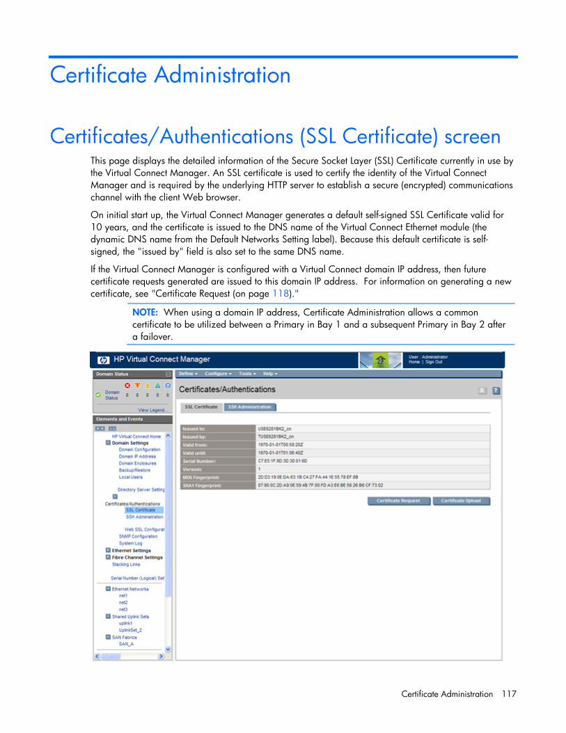
Certificate Administration 117
Certificate Administration
Certificates/Authentications (SSL Certificate) screen This page displays the detailed information of the Secure Socket Layer (SSL) Certificate currently in use by the Virtual Connect Manager. An SSL certificate is used to certify the identity of the Virtual Connect Manager and is required by the underlying HTTP server to establish a secure (encrypted) communications channel with the client Web browser.
On initial start up, the Virtual Connect Manager generates a default self-signed SSL Certificate valid for 10 years, and the certificate is issued to the DNS name of the Virtual Connect Ethernet module (the dynamic DNS name from the Default Networks Setting label). Because this default certificate is self-signed, the "issued by" field is also set to the same DNS name.
If the Virtual Connect Manager is configured with a Virtual Connect domain IP address, then future certificate requests generated are issued to this domain IP address. For information on generating a new certificate, see "Certificate Request (on page 118)."
NOTE: When using a domain IP address, Certificate Administration allows a common certificate to be utilized between a Primary in Bay 1 and a subsequent Primary in Bay 2 after a failover.

Certificate Administration 118
The following table describes the tables within the Certificate/Authentications (SSL Certificate) screen.
Row Description
Issued to The subject, or "Common Name," to which this SSL Certificate is issued. By default, this is the dynamic DNS name of the HP 1/10Gb VC-Enet Module. If a Virtual Connect domain IP address is configured, a new certificate request is issued to the domain IP address.
Issued by Name of the Certificate Authority (CA) that issued this SSL Certificate By default, the Virtual Connect Manager generates a self-signed certificate, which means the "Issued by" field contains the same dynamic DNS name as the "Issued for" field. If the Domain Administrator has requested a new certificate and it is signed by a CA, then the name of the CA is displayed.
Valid from The date and time starting when this certificate became valid
Valid until The date and time when this certificate becomes invalid
Serial Number Serial number of the certificate. This serial number is unique per Certificate Authority that issued it.
Version Version of the certificate
MD5 Fingerprint Unique fingerprint of the certificate, calculated using cryptographic hash function Message-Digest algorithm 5 (MD5). This fingerprint can be used to further verify that the correct certificate is being used.
SHA1 Fingerprint Unique fingerprint of the certificate, calculated using cryptographic hash function Secure Hash Algorithm 1 (SHA1). This fingerprint can be used to further verify that the correct certificate is being used.
Certificate Request This page displays a standardized certificate signing request generated by the Virtual Connect Manager. The content of the request in the text box can be sent to a Certificate Authority of your choice for signing. After it is signed by and returned from the Certificate Authority, you can upload the certificate by clicking Certificate Upload on the Certificates/Authentications (SSL Certificate) screen.
If a Virtual Connect domain IP address is configured for the Virtual Connect Manager at the time this certificate request is generated, the certificate request is issued to the domain IP address. Otherwise, the request is issued to the dynamic DNS name of the Virtual Connect Ethernet module. The certificate, by default, requests a valid duration of 10 years (this value is currently not configurable).

Certificate Administration 119
Note that a new certificate request is generated each time this web page is visited, so the content may not be the same each time.
Certificate Upload There are two methods for uploading certificates for use in the Virtual Connect Ethernet module:
• Paste the certificate contents into the text field, and then click Upload.
• Paste the URL of the certificate into the URL field, and then click Apply.
The certificate to be uploaded must be from a certificate request sent out and signed by a Certificate Authority for this particular Virtual Connect Manager. Otherwise, the certificate fails to match the private keys used to generate the certificate request, and the certificate is rejected. Also, if the Virtual Connect domain has been destroyed or re-imported, you need to repeat the steps for generating a certificate request and have it signed by a Certificate Authority again, because the private keys are destroyed and recreated along with the Virtual Connect domain.

Certificate Administration 120
If the new certificate is successfully accepted and installed by the Virtual Connect Manager, you are automatically logged out. The HTTP server must be restarted for the new certificate to take effect.
Certificates/Authentications (SSH Administration) This screen lists the current user (assuming administrator privileges) of each authorized SSH key and enables the user to add new keys. Only local users can have authorized SSH keys.
• SSH Fingerprint—Identifies the server and can be used to authenticate that the SSH client is connecting to the correct host.
• Authorized SSH Keys—Lists the authorized SSH key data for the currently logged in user.
• Add New SSH Keys—Allows the user to create or replace the authorized SSH keys. The user can enter the SSH keys in the text box or provide a URL to a file containing the user's SSH keys. The current content of the Authorized SSH Keys is replaced with the new list of SSH keys after clicking Set SSH Keys. The key file should contain the User Name of a local user at the end of the public key. Each key is associated with a local user account. If the local account does not exist for the User Name at the end of the SSH key file, the key authorization fails.

Certificate Administration 121
When a user has authorized one or more SSH keys, the user can delete all of them by clicking Clear SSH Keys. Removing the authorized SSH keys does not affect current SSH sessions.
Web SSL Configuration This screen enables you to change the currently configured SSL encryption strength. This screen is only available to users with Domain Administration privileges.
To change the current strength, select 'Any SSL Key Length,' to allow all SSL encryption, or 'Only Strong Key Lengths' to require strong encryption strength (at least 128 bits).
Click Apply to save changes, or click Cancel to keep current settings.

Certificate Administration 122
When the web SSL encryption strength is changed, logged in users are notified that they must reconnect.

Hardware information screens 123
Hardware information screens
Enclosure Information screen
The following table describes the rows within the Enclosure Information screen.
Row Description
Part Number The part number to be used when ordering an additional enclosure of this type
Product Name The common descriptive name of the enclosure
Serial Number The unique serial number of the enclosure
Asset Tag If configured, the asset tag of the enclosure, used for inventory control
Manufacturer Name of the enclosure manufacturer
Spare Part Number The part number to be used when ordering a replacement enclosure
Rack Name Name of the enclosure rack (assigned through the Onboard Administrator)
Time Zone The time zone assigned to the enclosure
Blade Bays Number of device bays in the enclosure
Interconnected Trays Number of interconnect trays in the enclosure
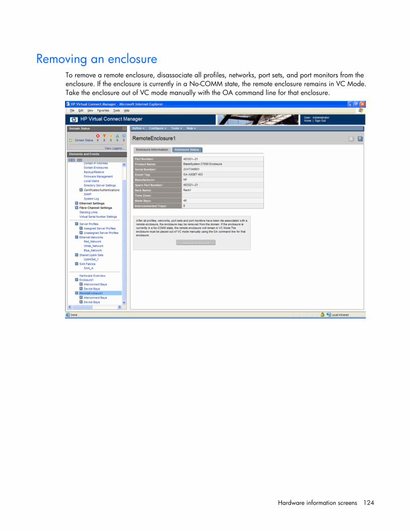
Hardware information screens 124
Removing an enclosure To remove a remote enclosure, disassociate all profiles, networks, port sets, and port monitors from the enclosure. If the enclosure is currently in a No-COMM state, the remote enclosure remains in VC Mode. Take the enclosure out of VC mode manually with the OA command line for that enclosure.
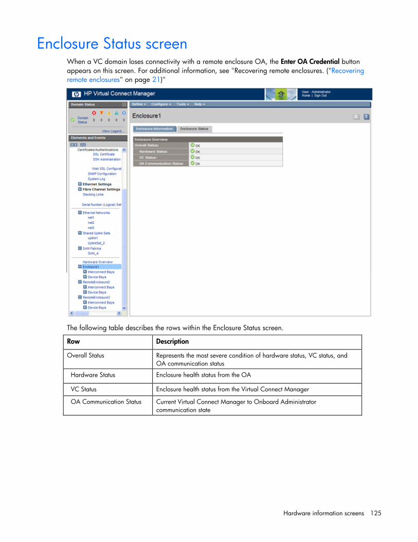
Hardware information screens 125
Enclosure Status screen When a VC domain loses connectivity with a remote enclosure OA, the Enter OA Credential button appears on this screen. For additional information, see "Recovering remote enclosures. ("Recovering remote enclosures" on page 21)"
The following table describes the rows within the Enclosure Status screen.
Row Description
Overall Status Represents the most severe condition of hardware status, VC status, and OA communication status
Hardware Status Enclosure health status from the OA
VC Status Enclosure health status from the Virtual Connect Manager
OA Communication Status Current Virtual Connect Manager to Onboard Administrator communication state

Hardware information screens 126
Interconnect Bays Status and Summary screen
The following table describes the rows within the Interconnect Bays Status table in the Interconnect Bays Status and Summary screen.
Row Description
Status Overall status of the interconnect bays in the enclosure
Rack Name Name of the enclosure rack (assigned through the Onboard Administrator)
Enclosure Name Name of the enclosure (assigned through the Onboard Administrator)
The following table describes the columns within the Interconnect Bays Summary table in the Interconnect Bays Status and Summary screen.
Column Description
Bay Bay number and connection type
Status Status of the interconnect module in the bay
Module UID icon (click to toggle UID state) and type of module installed in this bay
Power Icon indicates whether the interconnect module is powered on or off
Firmware Rev Firmware revision of the interconnect module installed in this bay

Hardware information screens 127
Causes for INCOMPATIBLE status When a module status is INCOMPATIBLE, details can be viewed in the System log ("System Log screen" on page 49). The system log provides information about why a module is marked incompatible so that proper corrective action can be taken.
Following is a list of reasons why a module might be INCOMPATIBLE and the suggested corrective action.
• Module adjacency
Typically, a module can only be in a bay next to a module of the same type. See the installation guidelines in the HP Virtual Connect for c-Class BladeSystem Setup and Installation Guide.
If a module is next to another module that it is not compatible with, both modules will be labeled as INCOMPATIBLE, since the rule applies to both modules.
Corrective action: Remove the adjacent incompatible modules and replace with modules that are compatible next to each other.
• Module replacement
If an interconnect module is being used by the domain, is physically removed, and then another module is put in the same bay, the new module must be the same type as the module previously in the bay.
If the physically removed module was NOT being used by the domain, the module can be replaced with a module of a different type.
VC-Enet modules are considered in use by the domain under the following conditions:
o Uplinks or downlinks are being used by networks/profiles
o The module is in interconnect bay 1 or bay 2 of the primary enclosure
VC-FC Modules In-Use by the Domain modules are considered in use by the domain if uplinks or downlinks are being used by fabrics or profiles
Corrective action: Remove the incompatible module and replace with the same module that previously existed. For more information, see "Module removal and replacement (on page 141)."
• Firmware version
Only modules with firmware versions supported by the firmware running on the primary module are compatible. All other versions of firmware modules cause the module to be marked as INCOMPATIBLE.
Corrective action: Use VCSU to update incompatible modules to the appropriate firmware versions for the domain.
• FC bay groups
In a multi-enclosure environment, all enclosures must have the same FC module configuration. For more information, see the multiple enclosure guidelines in the HP Virtual Connect for c-Class BladeSystem Setup and Installation Guide.
Corrective action: Remove the incompatible module and replace it with the correct module for the FC bay group that already exists.
• In a c3000 enclosure, FC modules are not supported in bay 2.

Hardware information screens 128
Interconnect Bay Summary screen (Ethernet module) This screen provides a summary of the interconnect module status and port information. To remove a module, see "Module removal and replacement (on page 141)" and "Administrative module removal (on page 142)."
The following table describes the rows within the Interconnect Bay Status (VC-Enet Module) table in the Bay Summary screen.
Row Description
Overall Status Represents the worst condition of OA Reported Status, VC Status, and OA Communication Status
Hardware Status Component health status from the Onboard Administrator
VC Status Component health status from the Virtual Connect Manager
OA Communication Status Current Virtual Connect Manager to Onboard Administrator communication state
Rack Name Name of the enclosure rack (assigned through the Onboard Administrator)
Enclosure Name Name of the enclosure (assigned through the Onboard Administrator)
Bay Number of the bay being summarized on this screen
Power Power state of the device

Hardware information screens 129
The following table describes the rows within the Interconnect Bay Information table in the Bay Summary screen.
Row Description
Part Number The part number to be used when ordering an additional module of this type
Product Name The common descriptive name of the module
Serial Number The unique serial number of the module
Dip Switch Setting The current physical setting of the system maintenance switches in a hexidecimal format, where the least significant four bits of the value correspond to the four switches and a bit value of 1 indicates the switch is in the "on" position.
Spare Part Number The part number to be used when ordering a replacement module of this type
Manufacturer The manufacturer of the module
Firmware Rev The current firmware revision of the module
The following table describes the columns within the Uplink Port Information table in the Bay Summary screen.

Hardware information screens 130
Column Description
Label Uplink port number
Network(s) Network name or the name of the shared uplink associated with this port
Status Displays whether the port is linked or unlinked
Connector Type Displays the physical type of the faceplate connector, type of pluggable module if one is present, or "Internal" to indicate the inter-switch link is active on the VC-Enet module.
LAG ID Identifies the group of ports that have been aggregated together to form an 802.3ad Link Aggregation Group. This ID is unique only within a single VC-Enet module, meaning the same LAG ID can be used on different VC-Enet modules, but it is only meaningful for ports within the same VC-Enet module.
Connected to Displays the MAC address of the device that this port is connected to on the other end. The device must support LLDP to display this information
Detailed Statistics Click to display detailed statistics about this port.
The following table describes the columns within the Server Port Information table in the Bay Summary screen.
Column Description
Label Server side port number (determined by the device bay and NIC)
Flex NIC Flexible network interface port
Physical server Number of the device bay and a description of the installed server blade
Network Network name or the name of the shared uplink associated with this port
Profile Name of the server blade profile
Status Displays whether the server blade is linked or unlinked
Detailed Statistics Click to display detailed statistics about this port
Port Detailed Statistics screen This screen provides details on Port Information, Port Status, Port Statistics, and Remote Device Information.
To reset the statistics, click Reset Statistics.

Hardware information screens 131
To refresh the statistics, click Refresh Statistics.
The following tables describe the rows within the Port Detailed Statistics screen.
Port Information Description
Port Number Relative Ethernet port number
Connector Type Type of port connector, for example RJ-45
Enclosure Bay Number of the enclosure bay where the port is located
Port Status Description
Speed Speed and duplex (where applicable) of the uplink port
Link Status Shows whether link is linked or unlinked
Trunking Mode Trunking mode of the port, for example AUTO
CFG Speed CFG speed setting of the port, for example AUTO
Port Statistic Description
reset_time Port reset time.
IfInOctets The total number of octets received on the interface, including framing characters.

Hardware information screens 132
Port Statistic Description
IfInUcastPkts The number of subnetwork-unicast packets delivered to a higher-layer protocol.
IfInNUcastPkts The number of non-unicast (subnetwork-broadcast or subnetwork-multicast) packets delivered to a higher-layer protocol.
IfInDiscards The number of inbound packets that were chosen to be discarded even though no errors had been detected to prevent their being delivered to a higher-layer protocol. One possible reason for discarding such a packet could be to free up buffer space.
IfInErrors The number of inbound packets that contained errors preventing them from being deliverable to a higher-layer protocol.
IfInUnknownProtos The number of packets received via the interface that were discarded because of an unknown or unsupported protocol.
IfOutOctets The total number of octets transmitted out of the interface, including framing characters.
IfOutUcastPkts The total number of packets that higher-level protocols requested be transmitted to a subnetwork-unicast address, including those that were discarded or not sent.
IfOutNUcastPkts The total number of packets that higher-level protocols requested be transmitted to a non-unicast (subnetwork-broadcast or subnetwork-multicast) address, including those that were discarded or not sent.
IfOutDiscards The number of outbound packets that were chosen to be discarded even though no errors had been detected to prevent their being transmitted. One possible reason for discarding such a packet could be to free up buffer space.
IfOutErrors The number of outbound packets that could not be transmitted because of errors.
IfOutQLen The length of the output packet queue (in packets).
IpInReceives The total number of input datagrams received from interfaces, including those received in error.
IpInHdrErrors The number of input datagrams discarded due to errors in their IP headers, including bad checksums, version number mismatch, other format errors, time-to-live exceeded, errors discovered in processing their IP options.
IpForwDatagrams The number of input datagrams for which this entity was not their final IP destination. As a result, an attempt was made to find a route to forward them to that final destination. In entities that do not act as IP Gateways, this counter includes only those packets that were Source-Routed via this entity, and the ones for which Source-Route option processing was successful.
IpInDiscards The number of input IP datagrams for which no problems were encountered to prevent their continued processing, but which were discarded (possibly for lack of buffer space). This counter does not include any datagrams discarded while awaiting re-assembly.
Dot1dBasePortDelayExceededDiscards
The number of frames discarded by this port due to excessive transit delay through the bridge. It is incremented by both transparent and source route bridges.

Hardware information screens 133
Port Statistic Description
Dot1dBasePortMtuExceededDiscards
The number of frames discarded by this port due to an excessive size. It is incremented by both transparent and source route bridges.
Dot1dBasePortInFrames The number of frames that have been received by this port from its segment. Note that a frame received on the interface corresponding to this port is only counted by this object if and only if it is for a protocol being processed by the local bridging function, including bridge management frames.
Dot1dBasePortOutFrames The number of frames that have been transmitted by this port to its segment. A frame transmitted on the interface corresponding to this port is counted by this object only if the frame is for a protocol being processed by the local bridging function, including bridge management frames.
Dot1dBasePortInDiscards Count of valid frames received that were discarded (filtered) by the Forwarding Process.
EtherStatsDropEvents The total number of events in which packets were dropped by the probe due to lack of resources. This number is not necessarily the number of packets dropped, but is just the number of times this condition has been detected.
EtherStatsMulticastPkts The total number of good packets received that were directed to a multicast address. This number does not include packets directed to the broadcast address.
EtherStatsBroadcastPkts The total number of good packets received that were directed to the broadcast address. This number does not include multicast packets.
EtherStatsUndersizePkts The total number of packets received that were less than 64 octets long (excluding framing bits, but including FCS octets) and were otherwise well-formed.
EtherStatsFragments The total number of packets received that were less than 64 octets in length (excluding framing bits, but including FCS octets) and had either a bad FCS with an integral number of octets (FCS Error) or a bad FCS with a non-integral number of octets (Alignment Error). It is normal for StatsFragments to increment because both runts, which are normal occurrences due to collisions, and noise hits are counted.
EtherStatsPkts64Octets The total number of packets (including bad packets) received that were 64 octets in length (excluding framing bits, but including FCS octets).
EtherStatsPkts65to127Octets The total number of packets (including bad packets) received that were between 65 and 127 octets in length inclusive (excluding framing bits, but including FCS octets).
EtherStatsPkts128to255Octets The total number of packets (including bad packets) received that were between 128 and 255 octets in length inclusive (excluding framing bits, but including FCS octets).
EtherStatsPkts256to511Octets The total number of packets (including bad packets) received that were between 256 and 511 octets in length inclusive (excluding framing bits, but including FCS octets).
EtherStatsPkts512to1023Octets The total number of packets (including bad packets) received that were between 512 and 1023 octets in length inclusive (excluding framing bits, but including FCS octets).

Hardware information screens 134
Port Statistic Description
EtherStatsPkts1024to1518Octets The total number of packets (including bad packets) received that were between 1024 and 1518 octets in length inclusive (excluding framing bits, but including FCS octets).
EtherStatsOversizePkts The total number of packets received that were longer than 1518 octets (excluding framing bits, but including FCS octets) and were otherwise well-formed.
EtherStatsJabbers The total number of packets received that were longer than 1518 octets (excluding framing bits, but including FCS octets), and had either a bad FCS with an integral number of octets (FCS Error) or a bad FCS with a non-integral number of octets (Alignment Error). This definition of jabber is different than the definition in IEEE-802.3 section 8.2.1.5 (10BASE5) and section 10.3.1.4 (10BASE2). These documents define jabber as the condition where any packet exceeds 20 ms. The allowed range to detect jabber is between 20 ms and 150 ms.
EtherStatsOctets The total number of octets of data (including those in bad packets) received on the FCS octets). This object can be used as a reasonable estimate of Ethernet utilization. If greater precision is required, the StatsPkts and StatsOctets objects should be sampled before and after a common interval. The differences in the sampled values are Pkts and Octets, respectively, and the number of seconds in the interval is Interval. These values are used to calculate the Utilization as follows: Utilization = [(Pkts * (9.6 + 6.4) + (Octets * .8)) / (Interval * 10,000)]. The result of this equation is the value Utilization which is the percent utilization of the Ethernet segment on a scale of 0 to 100 percent.
EtherStatsPkts The total number of packets (including bad packets, broadcast packets, and multicast packets) received.
EtherStatsCollisions The best estimate of the total number of collisions on this Ethernet segment. The value returned depends on the location of the RMON probe. Section 8.2.1.3 (10BASE-5) and section 10.3.1.3 (10BASE-2) of IEEE standard 802.3 states that a station must detect a collision, in the receive mode, if three or more stations are transmitting simultaneously. A repeater port must detect a collision when two or more stations are transmitting simultaneously. Therefore, a probe placed on a repeater port could record more collisions than a probe connected to a station on the same segment would. Probe location plays a much smaller role when considering 10BASE-T. 14.2.1.4 (10BASE-T) of IEEE standard 802.3 defines a collision as the simultaneous presence of signals on the DO and RD circuits (transmitting and receiving at the same time). A 10BASE-T station can only detect collisions when it is transmitting. Therefore, probes placed on a station and a repeater should report the same number of collisions. Additionally, an RMON probe inside a repeater should ideally report collisions between the repeater and one or more other hosts (transmit collisions as defined by IEEE 802.3k) plus receiver collisions observed on any coax segments to which the repeater is connected.

Hardware information screens 135
Port Statistic Description
EtherStatsCRCAlignErrors The total number of packets received that had a length (excluding framing bits, but including FCS octets) of between 64 and 1518 octets, inclusive, but had either a bad FCS with an integral number of octets (FCS Error) or a bad FCS with a non-integral number of octets (Alignment Error).
TXNoErrors All packets transmitted without errors, less oversized packets.
RXNoErrors All packets received without errors, less oversized and undersized packets.
Dot3StatsAlignmentErrors A count of frames received on a particular interface that are not an integral number of octets in length and do not pass the FCS check. The count represented by an instance of this object is incremented when the alignmentError status is returned by the MAC service to the LLC (or other MAC user). According to the conventions of IEEE 802.3 Layer Management, received frames for which multiple error conditions are obtained are counted exclusively according to the error status presented to the LLC. This counter does not increment for 8-bit wide group encoding schemes.
Dot3StatsFCSErrors A count of frames received on a particular interface that are an integral number of octets in length but do not pass the FCS check. This count does not include frames received with a frame-too-long or frame-too-short error. The count represented by an instance of this object is incremented when the frameCheckError status is returned by the MAC service to the LLC (or other MAC user). According to the conventions of IEEE 802.3 Layer Management, received frames for which multiple error conditions are obtained are counted exclusively according to the error status presented to the LLC. Coding errors detected by the physical layer for speeds above 10 Mb/s will cause the frame to fail the FCS check.
Dot3StatsSingleCollisionFrames A count of successfully transmitted frames on a particular interface for which transmission is inhibited by exactly one collision. A frame that is counted by an instance of this object is also counted by the corresponding instance of either the ifOutUcastPkts, ifOutMulticastPkts, or ifOutBroadcastPkts, and is not counted by the corresponding instance of the dot3StatsMultipleCollisionFrames object. This counter does not increment when the interface is operating in full-duplex mode.
Dot3StatsMultipleCollisionFrames A count of successfully transmitted frames on a particular interface for which transmission is inhibited by more than one collision. A frame that is counted by an instance of this object is also counted by the corresponding instance of either the ifOutUcastPkts, ifOutMulticastPkts, or ifOutBroadcastPkts, and is not counted by the corresponding instance of the dot3StatsSingleCollisionFrames object. This counter does not increment when the interface is operating in full-duplex mode.
Dot3StatsSQETestErrors A count of times that the SQE TEST ERROR message is generated by the PLS sublayer for a particular interface. The SQE TEST ERROR is set in accordance with the rules for verification of the SQE detection mechanism in the PLS Carrier Sense Function as described in IEEE Std. 802.3, 1998 Edition, section 7.2.4.6. This counter does not increment on interfaces operating at speeds greater than 10 Mb/s or operating in full-duplex mode.

Hardware information screens 136
Port Statistic Description
Dot3StatsDeferredTransmissions A count of frames for which the first transmission attempt on a particular interface is delayed because the medium is busy. The count represented by an instance of this object does not include frames involved in collisions. This counter does not increment when the interface is operating in full-duplex mode.
Dot3StatsLateCollisions The number of times that a collision is detected on a particular interface later than one slotTime into the transmission of a packet. A (late) collision included in a count represented by an instance of this object is also considered as a (generic) collision for purposes of other collision-related statistics. This counter does not increment when the interface is operating in full-duplex mode.
Dot3StatsExcessiveCollisions A count of frames for which transmission on a particular interface fails due to excessive collisions. This counter does not increment when the interface is operating in full-duplex mode.
Dot3StatsInternalMacTransmitErrors
A count of frames for which transmission on a particular interface fails due to an internal MAC sublayer transmit error. A frame is only counted by an instance of this object if it is not counted by the corresponding instance of either the dot3StatsLateCollisions object, the dot3StatsExcessiveCollisions object, or the dot3StatsCarrierSenseErrors object. The precise meaning of the count represented by an instance of this object is implementation-specific. In particular, an instance of this object may represent a count of transmission errors on a particular interface that are not otherwise counted.
Dot3StatsCarrierSenseErrors The number of times that the carrier sense condition was lost or never asserted when attempting to transmit a frame on a particular interface. The count represented by an instance of this object is incremented, at most, once per transmission attempt, even if the carrier sense condition fluctuates during a transmission attempt. This counter does not increment when the interface is operating in full-duplex mode.
Dot3StatsFrameTooLongs A count of frames received on a particular interface that exceeds the maximum permitted frame size. The count represented by an instance of this object is incremented when the frameTooLong status is returned by the MAC service to the LLC (or other MAC user). According to the conventions of IEEE 802.3 Layer Management, received frames for which multiple error conditions are obtained are counted exclusively according to the error status presented to the LLC.
Dot3StatsInternalMacReceiveErrors A count of frames for which reception on a particular interface fails due to an internal MAC sublayer receive error. A frame is only counted by an instance of this object if it is not counted by the corresponding instance of either the dot3StatsFrameTooLongs object, the dot3StatsAlignmentErrors object, or the dot3StatsFCSErrors object. The precise meaning of the count represented by an instance of this object is implementation-specific. In particular, an instance of this object may represent a count of receive errors on a particular interface that are not otherwise counted.

Hardware information screens 137
Port Statistic Description
Dot3StatsSymbolErrors For an interface operating at 100 Mb/s, the number of times an invalid data symbol occurred when a valid carrier was present. For an interface operating in half-duplex mode at 1000 Mb/s, the number of times the receiving media is non-idle (a carrier event) for a period of time equal to or greater than slotTime, and during which there was at least one occurrence of an event that causes the PHY to indicate 'Data reception error' or 'carrier extend error' on the GMII. For an interface operating in full-duplex mode at 1000 Mb/s, the number of times the receiving media is non-idle (a carrier event) for a period of time equal to or greater than minFrameSize, and during which there was at least one occurrence of an event that causes the PHY to indicate 'Data reception error' on the GMII. The count represented by an instance of this object is incremented, at most, once per carrier event, even if multiple symbol errors occur during the carrier event. This count does not increment if a collision is present.
Dot3ControllnUnknownOpcodes A count of MAC Control frames received on this interface that contain an opcode that is not supported by this device.
Dot3InPauseFrames A count of MAC Control frames received on this interface with an opcode indicating the PAUSE operation. This counter does not increment when the interface is operating in half-duplex mode.
Dot3OutPauseFrames A count of MAC Control frames transmitted on this interface with an opcode indicating the PAUSE operation. This counter does not increment when the interface is operating in half-duplex mode.
IfHCInOctets The total number of octets received on the interface, including framing characters. This object is a 64-bit version of ifInOctets.
IfHCInUcastPkts The number of packets, delivered by this sublayer to a higher sublayer, which were not addressed to a multicast or broadcast address at this sublayer. This object is a 64-bit version of ifInUcastPkts.
IfHCInMulticastPkts The number of packets, delivered by this sublayer to a higher sublayer, which were addressed to a multicast address at this sublayer. For a MAC layer protocol, this includes both Group and Functional addresses. This object is a 64-bit version of ifInMulticastPkts.
IfHCInBroadcastPkts The number of packets, delivered by this sublayer to a higher sublayer, which were addressed to a broadcast address at this sublayer. This object is a 64-bit version of ifInBroadcastPkts.
IfHCOutOctets The total number of octets transmitted out of the interface, including framing characters. This object is a 64-bit version of ifOutOctets.
IfHCOutUcastPkts The total number of packets that higher-level protocols requested be transmitted, and which were not addressed to a multicast or broadcast address at this sublayer, including those that were discarded or not sent. This object is a 64-bit version of ifOutUcastPkts.
IfHCOutMulticastPkts The total number of packets that higher-level protocols requested be transmitted, and which were addressed to a multicast address at this sublayer, including those that were discarded or not sent. For a MAC layer protocol, this includes both Group and Functional addresses. This object is a 64-bit version of ifOutMulticastPkts.

Hardware information screens 138
Port Statistic Description
IfHCOutBroadcastPckts The total number of packets that higher-level protocols requested be transmitted, and which were addressed to a broadcast address at this sublayer, including those that were discarded or not sent. This object is a 64-bit version of ifOutBroadcastPkts.
Remote Device Information Description
remote_type Type of remote device. Virtual Connect uses this information to configure the link as an uplink, a stacking link, or to disable. This information is based on the LLDP data sent by the device to which the port is attached.
remote_discovered_time Time the remote device was identified, represented in seconds. This information is based on the LLDP data sent by the device to which the port is attached.
remote_chassis_id_type Chassis ID subtype of the remote device.
remote_chassis_id Chassis ID value of the remote device.
remote_port_id_type Port ID subtype of the remote device.
remote_port_id Port ID value of the remote device.
remote_port_desc Port description of the remote device.
remote_system_name System name of the remote device. If the remote device is a VC-Enet module, remote_system_name is the remote device's VC domain name.
remote_system_desc Description of the remote system. If the remote device is a VC-Enet module, remote_system_desc is the module's hardware description and firmware revision.
remote_system_capabilities System capabilities of the remote system, for example, repeater, bridge, or router.
remote_mgmt_addr_type Management address subtype of the remote device, for example, IPv4, IPv6, or DNS.
remote_mgmt_addr Management address of the remote device.

Hardware information screens 139
Interconnect Bay Summary screen (VC-FC Module) This screen provides a summary of the interconnect module status and port information. To remove a module from the domain, see "Administrative module removal (on page 142)."
The following table describes the rows within the Interconnect Bay Status (VC-FC Module) table in the Bay Summary screen.
Row Description
Overall Status Represents the worst condition of OA Reported Status, VC Status, and OA Communication Status
Hardware Status Component health status from the Onboard Administrator
VC Status Component health status from the Virtual Connect Manager
OA Communication Status Current Virtual Connect Manager to Onboard Administrator communication state
Rack Name Name of the enclosure rack (assigned through the Onboard Administrator)
Enclosure Name Name of the enclosure (assigned through the Onboard Administrator)
Bay Number of the bay being summarized on this screen
Power Status Control Power state of the device
Uplink Ports Used Number of uplink ports used to connect to the SAN. This number specifies the oversubscription ratio (4:1, 8:1, or 16:1).

Hardware information screens 140
The following table describes the rows within the Interconnect Bay Information table in the Bay Summary screen.
Row Description
Part Number The part number to be used when ordering an additional module of this type
Product Name The common descriptive name of the module
Serial Number The unique serial number of the module
Spare Part Number The part number to be used when ordering a replacement module of this type
Manufacturer The manufacturer of the module
Node WWN WWN assigned to the module
The following table describes the rows within the Uplink Port information table in the Bay Summary screen.
Column Description
Port The uplink port number
WWN Either the World Wide Name assigned to the port or the Server Factory Default, if not assigning WWNs

Hardware information screens 141
Column Description
SAN Fabric Name of the SAN Fabric connected to the uplink port
Port Speed Speed setting of the uplink port
Connector Status Status of the uplink port
Connected To MAC address of the device that this port is connected to on the other end. The device must support LLDP to display this information.
The following table describes the rows within the Server Port Information table in the Bay Summary Screen. Click Less < to display only the Port, Server Blade, SAN Fabric, Connected To, and Profile columns. Click More > to display all columns.
Column Description
Port Port number
Server Blade Server blade bay location
SAN Fabric Name of the SAN Fabric connected to this port
Connected To WWN address of the device that this port is connected to on the other end
Profile Server Profiles with connections to this port
HBA Port HBA port number
HBA Port Speed Speed setting of the HBA port
HBA Port Status Status of the HBA port
HBA WWPN Either the World Wide Port Name assigned to the port or the Server Factory Default, if not assigning WWNs
Module removal and replacement Beginning with VC v3.00, it is no longer necessary to administratively remove a module if the module is not in use. If a module is not in use and is physically removed, it is automatically removed from the domain.
However, if you are removing a module that is in interconnect bay 1 or bay 2 of the primary enclosure, you must first delete the domain, and then recreate it after the module has been removed.
As a general rule, if a module has been configured and is in use by the domain, this module can only be replaced with a module of the same type. For example, an HP 1/10Gb-F VC-Enet Module should be replaced with another HP 1/10Gb-F VC-Enet Module only. However, the following group of modules are compatible and can be used to replace another module in this list:
• HP 4Gb VC FC module
• HP VC 4Gb module (with enhanced NPIV)
• HP VC 8Gb 20-Port FC module
When replacing a module with a module of another type, do the following:
1. Remove all port assignments.

Hardware information screens 142
2. Remove all uplinks and downlinks.
3. Replace the module.
Administrative module removal The Remove from Domain feature enables users to remove an interconnect module from the Virtual Connect domain without having to delete the entire domain, or having the bay permanently configured for a specific interconnect module type.
Removing a VC-Enet module and installing it in another enclosure causes the configuration information on that module to be cleared. This action prevents a configured spare from overwriting configuration data in another enclosure.
To temporarily remove the module from the domain, do not click Remove from Domain. Simply re-install it into the enclosure.
To permanently remove the module from the Virtual Connect domain, be sure the following conditions are met:
NOTE: The attachment of stacking link cables to a module does not prevent a Remove from Domain action.
• VC-Enet conditions:
o The user must have Domain privileges.
o The module must be physically removed from the bay.
o The interconnect bay must remain empty for this procedure.
o The module uplink and downlink ports cannot be in use by networks, uplink sets, or profiles (including FC profiles) in the enclosure.
o Port monitoring cannot be enabled on that bay.
• VC-FC conditions:
o The user must have Domain privileges.
o The module must be physically removed from the bay.
o The interconnect bay must remain empty for this procedure.
o Change all fabrics on that module to Unassigned for all Virtual Connect profile configurations.
• If removing an FC module from a multi-enclosure domain, all FC modules in that bay in each enclosure must be missing. Removing one of the missing modules removes the module from all enclosures.
If these conditions are met, click Remove from Domain.
If these conditions are not met, the Remove from Domain button is not available, or an error message appears.
If a VC-Enet module is restarted from a power-cycle or reboot, or the module is removed and inserted, a link might not be re-established between the module and the ports of an NC364m mezzanine card. If the server is rebooted, the link is established on all ports on both sides of the connection. Manually toggling the link from the server should also restore the link.

Hardware information screens 143
Interconnect Bay Overall Status icon definitions
Icon Operational state Meaning Corrective action
OK Device is fully operational. None
Unknown Device operational state cannot be determined.
Check Onboard Administrator communication.
(blue)
Initializing Device is initializing. Wait until initialization is complete. (This icon should only be seen at startup.)
(yellow)
Degraded Device is partially operational, but capability is lost.
Check and correct the Onboard Administrator error condition.
(orange)
Misconfigured Device has a configuration error. Correct the Virtual Connect Manager configuration attributes.
(orange)
Incompatible Device does not match the configuration.
Remove the incorrect hardware. Insert the correct module.
(orange)
No communication Cannot communicate with the device.
Check the physical connections and IP address.
Missing Device is configured but not accessible.
Insert the correct hardware module.
Failed Device is not operational because of an error.
Reset the device or application, or replace the device.
Interconnect Bay OA Reported Status icon definitions
Icon Operational state Meaning Corrective action
OK Device is fully operational. None
Unknown Device operational state cannot be determined.
Check Onboard Administrator communication.
(yellow)
Degraded Device is partially operational, but capacity is lost.
Check and correct the Onboard Administrator error condition.
Failed Device is not operational because of an error.
Check and correct the Onboard Administrator error condition.
Interconnect Bay VC Status icon definitions
Icon Operational state Meaning Corrective action
OK Device is fully operational. None
Unknown Device operational state cannot be determined.
Check Onboard Administrator communication.
Disabled User has administratively disabled the device.
Enable the component in Virtual Connect Manager.
(blue)
Initializing Device is initializing. Wait until initialization is complete. (This icon should only be seen at startup.)

Hardware information screens 144
Icon Operational state Meaning Corrective action
(blue)
Unavailable Device is active but unable to provide service.
Attempt to re-establish connection.
(yellow)
Degraded Device is partially operational, but capacity is lost.
Check and correct the Onboard Administrator error condition.
(orange)
Misconfigured Device has a configuration error. Correct the Virtual Connect Manager configuration attributes.
(orange)
Incompatible Device does not match the configuration.
Remove the incorrect hardware. Insert the correct module.
(orange)
No communication Cannot communicate with the device.
Check the physical connections and IP address.
Missing Device is configured but not accessible.
Insert the correct hardware module.
Failed Device is not operational because of an error.
Reset the device or application, or replace the device.
Interconnect Bay OA Communication Status icon definitions
Icon Operational state Meaning Corrective action
OK Device is fully operational. None
Failed Cannot communicate with the device.
Do one or more of the following: • Reset the interconnect module. • Check if the physical device is
properly seated in the bay. • Check the IP address.
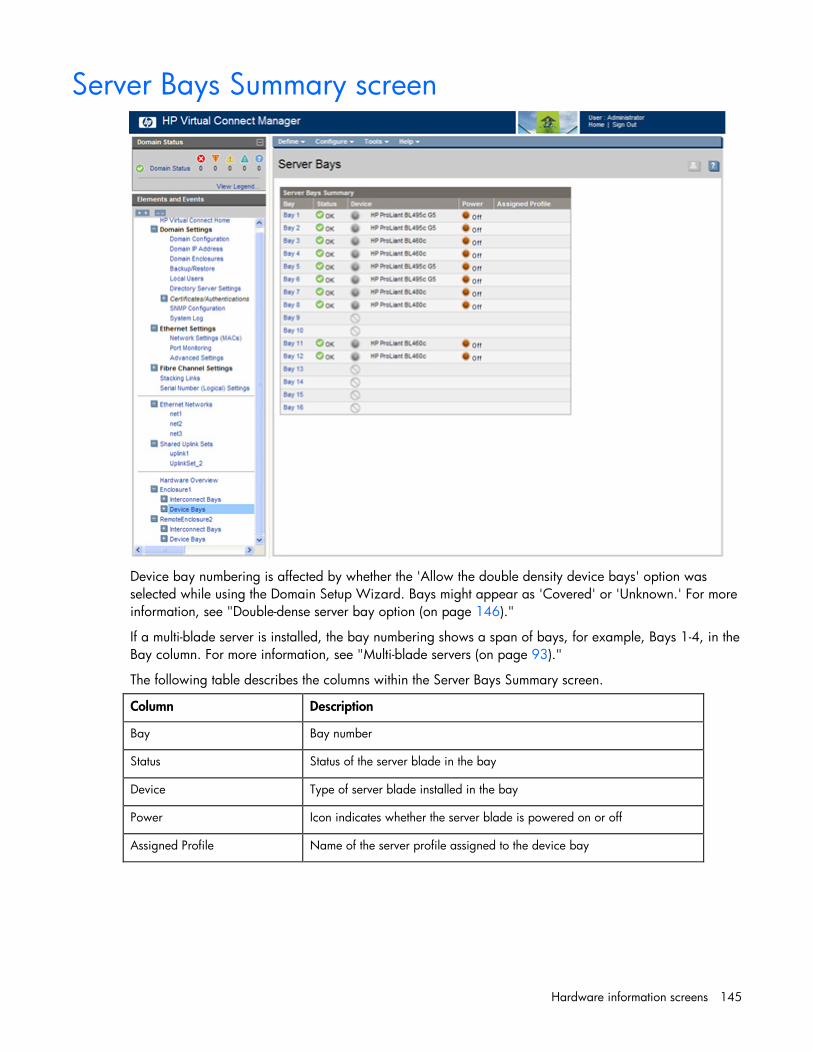
Hardware information screens 145
Server Bays Summary screen
Device bay numbering is affected by whether the 'Allow the double density device bays' option was selected while using the Domain Setup Wizard. Bays might appear as 'Covered' or 'Unknown.' For more information, see "Double-dense server bay option (on page 146)."
If a multi-blade server is installed, the bay numbering shows a span of bays, for example, Bays 1-4, in the Bay column. For more information, see "Multi-blade servers (on page 93)."
The following table describes the columns within the Server Bays Summary screen.
Column Description
Bay Bay number
Status Status of the server blade in the bay
Device Type of server blade installed in the bay
Power Icon indicates whether the server blade is powered on or off
Assigned Profile Name of the server profile assigned to the device bay

Hardware information screens 146
Double-dense server bay option If the 'Allow the double density device bays' option was selected while using the Domain Setup Wizard, VC Manager displays the server bays as double-dense, regardless of the actual hardware installed.
For example, if a full-height server blade is installed in physical Bay 1 of a double-dense enabled enclosure, Bay 1A and Bay 1B in VC Manager are displayed as 'Covered.' If a double-dense server blade is installed in physical Bay 1, Bay 1 in VC Manager is displayed as COVERED, and Bays 1A and 1B display the appropriate double-dense server blade information.
If VC Manager is downgraded to a version lower than v1.31, the double-dense bays and servers are no longer displayed within the VC Manager. Any profiles associated with a double-dense bay are unassigned.

Hardware information screens 147
Use of the double-dense server bay option requires OA version 2.20 or higher. If the OA is downgraded to a lower version, subsequent recovery of the double-dense enabled enclosure results in bays A and B being marked 'Unknown.'

Hardware information screens 148
Server Bay Overall Status icon definitions
Icon Operational state Meaning Corrective action
OK Device is fully operational. None
Unknown Device operational state cannot be determined.
Check Onboard Administrator communication.
(blue)
Initializing Device is initializing. Wait until initialization is complete. (This icon should only be seen at startup.)
(blue)
Profile pending Device has a pending profile assignment.
Turn server power off and apply the new profile.
(yellow)
Degraded Device is partially operational, but capacity is lost.
Check and correct the Onboard Administrator error condition.
(orange)
Misconfigured Device has a configuration error. Correct the Virtual Connect Manager configuration attributes.
(orange)
Incompatible Device does not match the configuration.
BIOS version level is not at a level that supports Virtual Connect.
(orange)
No communication Cannot communicate with the device.
Check the physical connections and IP address.
(orange)
Missing data VCM is missing data about one or more blades in the multi-blade server.
Check that the blades and SBL that comprise the multi-blade server are installed correctly and functioning properly.
Missing Device is configured but not accessible.
Insert the correct hardware module.
Failed Device is not operational because of an error.
Reset the device or application, or replace the device.
Server Bay OA Reported Status icon definitions
Icon Operational state Meaning Corrective action
OK Device is fully operational. None
Unknown Device operational state cannot be determined.
Check Onboard Administrator communication.
(yellow)
Degraded Device is partially operational, but capacity is lost.
Check and correct the Onboard Administrator error condition.
Failed Device is not operational because of an error.
Check and correct the Onboard Administrator error condition.
Server Bay VC Status icon definitions
Icon Operational state Meaning Corrective action
OK Device is fully operational. None

Hardware information screens 149
Icon Operational state Meaning Corrective action
Unknown Device operational state cannot be determined.
Check Onboard Administrator communication.
Disabled User has administratively disabled the device.
Enable the component in Virtual Connect Manager.
(blue)
Initializing Device is initializing. Wait until initialization is complete. (This icon should only be seen at startup.)
(blue)
Profile pending Device has a pending profile assignment.
Turn server power off and apply the new profile.
(yellow)
Degraded Device is partially operational, but capacity is lost.
Check and correct the Onboard Administrator error condition.
(orange)
Misconfigured Device has a configuration error. Correct the Virtual Connect Manager configuration attributes.
(orange)
Incompatible Device does not match the configuration.
BIOS level is not at a level that supports Virtual Connect.
(orange)
No communication Cannot communicate with the device.
Check the physical connections and IP address.
Missing Device is configured but not accessible.
Insert the correct hardware module.
Failed Device is not operational because of an error.
Reset the device or application, or replace the device.
Server Bay OA Communication Status icon definitions
Icon Operational state Meaning Corrective action
OK Device is fully operational. None
Failed Cannot communicate with the device.
Do one or more of the following: • Reset the interconnect module. • Check if the physical device is
properly seated in the bay. • Check the IP address.

Hardware information screens 150
Server Bay Status screen
To change the power state of the server blade, click Momentary Press.
To power the server blade on or off, click Press and Hold.
The following table describes the rows within the Server Bay Status table in the Server Bay Status screen.
Server Bay Status
Row Description
Overall Status Represents the worst condition of Hardware Status, VC Status, and OA Communication Status
Hardware Status Component health status from the Onboard Administrator
VC Status Component health status from the Virtual Connect Manager
OA Communication Status Current Virtual Connect Manager to Onboard Administrator communication state
Assigned Server Profile Name of the profile currently assigned to the server blade in this bay
Enclosure Name Name of the enclosure where this server blade is installed
UID Icon indicates whether the UID is illuminated or not illuminated.

Hardware information screens 151
Row Description
Power Status/Control Icon indicates whether the server blade in that bay is powered on or off.
The following table describes the rows within the Server Blade Information table in the Server Bay Status screen.
Server Blade Information
Row Description
Serial Number The unique serial number of the server blade
Product Name The common descriptive name of the server blade
Server Name If configured, the server name of the installed server blade
Part Number The part number to be used when ordering an additional or replacement server blade of this type
Asset Tag If configured, the asset tag of the installed server blade
Monarch Bay (multi-blade servers only)
Identifies the monarch bay in the multi-blade server
All Bays (multi-blade servers only)
Identifies all of the bays in the multi-blade server

Hardware information screens 152
The following table describes the columns within the Server Ethernet Adapter Information table in the Server Bay Status screen.
Server Ethernet Adapter Information
Column Description
Ethernet adapter Port number where the adapter is installed
Flex NIC Flexible network interface port
Location Connection location of this adapter
Model Type of adapter installed
MAC Address MAC address of the Ethernet adapter
Network Network name associated with this adapter
Connected to Bay number
The following table describes the columns within the SAN Ports table in the Server Bay Status screen.
SAN Ports
Column Description
Port Number Relative Fibre Channel Port number
Adapter Mezzanine number where the HBA is connected
Model Type of mezzanine installed
WWN VC-Assigned WWN or "Server Factory Default" if not assigning WWNs
Connected to Bay number

Hardware information screens 153
Server Bay Status screen - multi-blade servers
To change the power state of the server blade, click Momentary Press.
To power the server blade on or off, click Press and Hold.
The following table describes the rows within the Server Bay Status table in the Server Bay Status screen.
Server Bay Status
Row Description
Overall Status Represents the worst condition of Hardware Status, VC Status, and OA Communication Status
Hardware Status Component health status from the Onboard Administrator
VC Status Component health status from the Virtual Connect Manager
OA Communication Status Current Virtual Connect Manager to Onboard Administrator communication state
Assigned Server Profile Name of the profile currently assigned to the server blade in this bay

Hardware information screens 154
Row Description
Enclosure Name Name of the enclosure where this server blade is installed
UID Icon indicates whether the UID is illuminated or not illuminated.
Power Status/Control Icon indicates whether the server blade in that bay is powered on or off.
The following table describes the rows within the Server Blade Information table in the Server Bay Status screen.
Server Blade Information
Row Description
Serial Number The unique serial number of the server blade
Product Name The common descriptive name of the server blade
Server Name If configured, the server name of the installed server blade
Part Number The part number to be used when ordering an additional or replacement server blade of this type
Asset Tag If configured, the asset tag of the installed server blade
Monarch Bay (multi-blade servers only)
Identifies the monarch bay in the multi-blade server
All Bays (multi-blade servers only)
Identifies all of the bays in the multi-blade server
The following table describes the columns within the Server Ethernet Adapter Information table in the Server Bay Status screen.
Server Ethernet Adapter Information
Column Description
Device Bay Identifies the bay whose ports are shown in that group
Ethernet adapter Port number where the adapter is installed
Flex NIC Flexible network interface port
Location Connection location of this adapter
Model Type of adapter installed
MAC Address MAC address of the Ethernet adapter
Network Network name associated with this adapter
Connected to Bay number
The following table describes the columns within the SAN Ports table in the Server Bay Status screen.
SAN Ports
Column Description
Device Bay Identifies the bay whose ports are shown in that group

Hardware information screens 155
Column Description
Port Number Relative Fibre Channel Port number
Adapter Mezzanine number where the HBA is connected
Model Type of mezzanine installed
WWN VC-Assigned WWN or "Server Factory Default" if not assigning WWNs
Connected to Bay number

Acronyms and abbreviations 156
Acronyms and abbreviations
CFG constant frequency generator
CHAP Challenge Handshake Authentication Protocol
DNS domain name system
DO data object
FC
Fibre Channel
FCS
Frame Check Sequence
GMII
Gigabit media independent interface
HBA
host bus adapter
LACP
Link Aggregation Control Protocol
LAG link aggregation group
LAG ID link aggregation group ID
LDAP Lightweight Directory Access Protocol

Acronyms and abbreviations 157
LLDP
Link Layer Discovery Protocol
MAC
Media Access Control
NPIV
N_Port ID Virtualization
OA
Onboard Administrator
PHY physical layer device
PLS physical signaling
POST Power-On Self Test
RBSU ROM-Based Setup Utility
RD
receive data
RDP
Rapid Deployment Pack
RMON
remote monitoring
SIM
Systems Insight Manager
SMI-S Storage Management Initiative Specification
SNIA Storage Networking Industry Association

Acronyms and abbreviations 158
SSL
Secure Sockets Layer
TCN
Spanning Tree Topology Change Notification
VID
VLAN ID
VLAN
virtual local-area network
WWN World Wide Name

Glossary 159
Glossary
external port The Ethernet connectors (10GBASE-CX4 and RJ45) on the faceplate of the VC-Enet module labeled as ports 1-8, X1, and X2.
shared server links
A feature that enables each server link to be shared among multiple networks with the use of VLAN tagging.
shared uplink port
An Ethernet uplink port that carries the traffic for multiple Virtual Connect networks. Each associated Virtual Connect network is mapped to a specific VLAN on the external connection and appropriate VLAN tags are removed or added as Ethernet packets enter or leave the Virtual Connect domain.
shared uplink port set
A set of Ethernet uplinks that are used together to provide improved throughput and availability to a group of associated Virtual Connect networks. Each associated Virtual Connect network is mapped to a specific VLAN on the external connection and appropriate VLAN tags are removed or added as Ethernet packets enter or leave the Virtual Connect domain.
Smart Link
A feature that, when enabled, configures a Virtual Connect network so that if all external uplinks lose link to external switches, Virtual Connect will drop the Ethernet link on all local server blade Ethernet ports connected to that network.
stacking port A VC-Enet module external port used to connect to other VC-Enet modules within an active Virtual Connect domain. Stacking ports are automatically identified by the VC-Enet modules. The port number (port ID) is lit amber.
uplink port
An external port that is configured within Virtual Connect for use as a connection to external networking equipment. Uplink ports are defined within Virtual Connect by the enclosure name, interconnect bay containing the module, and the port number. The port number (port ID) for uplink ports is lit green.
uplink port set
A set of uplinks that are used together to provide improved throughput and availability for a single Virtual Connect network connection to external networking equipment.

Index 160
A About menu 12 accessing HP Virtual Connect Manager 10 ActiveX 9 adding a user 31 adding an LDAP group 38 adding enclosures 27 adding new users 34 administrative module removal 142 Advanced Network Settings 57 Advanced Profile Settings 103
B backup domain 29 bandwidth assignment 98 boot paramaters, Fibre Channel 107 Brocade switch 83, 85 browser requirements 9, 10
C certificate administration 117 certificate upload 119 certificate, requesting 118 Cisco switch 86 CLI (Command Line Interface) 11 command line interface, using 11 command line overview 11 connection mode 55 connection mode, changing 54, 57, 59 connectivity 100 cookies 9 covered device bay 145, 146
D define a server profile 100 define network 54, 55 define SAN fabric 83 define server VLAN mappings 104 define shared uplink set 74, 76 delete a domain 24 delete a server profile 109
deleting a network 57, 59 deleting a user 31 device bay, information 145 Directory Settings (Directory Certificate) 39 Directory Settings (Directory Groups) 37 Directory Settings (Directory Server) 36 documentation 6 domain name 23 domain overview 22 Domain Settings (Backup/Restore) 29 Domain Settings (Domain Configuration) screen 23 Domain Settings (Domain IP Address) 25 Domain Settings (Enclosures) 26 Domain Settings (Local Users) 31 Domain Status screen 17 Domain Status summary 15 domain, deleting 23, 24 double-dense server blades 146
E edit a server profile 110 edit a shared uplink set 77 edit an Ethernet network 57, 59 edit SAN fabric 89 enable strong passwords 31 enclosure information 123 enclosure serial number 22 enclosure status information 125 enclosure, removing 29, 124 enclosures view 18 Ethernet connections 100, 103, 104, 107, 109,
113 Ethernet Networks (Summary) 59 Ethernet networks, viewing 59 Ethernet Settings (Advanced Settings) 68 Ethernet Settings (MAC Addresses) 62 Ethernet Settings (Port Monitoring) 64 export support information 20
F fabric switch, enabling NPIV 85 failover 21 Fast MAC Cache Failover 68, 72
Index

Index 161
FC connections 100, 109, 113 Fibre Channel boot parameters 107 Fibre Channel settings (WWN) 90, 103 firmware, Onboard Administrator requirements 10 firmware, updating 23 Flex-10 configuration 96 Flex-10 overview 94
G graphical view 18
H homepage, Virtual Connect Manager 12
I icons 19, 20, 143, 144, 148, 149 IGMP snooping 68, 72 iLO 2 connector 10 importing enclosures 27 incompatible status, causes 127 interconnect bay, summary 126, 128, 139 Internet Explorer support 9 iSCSI support 63
J Javascript 9 jumbo frames 55
L LAG ID 128 LDAP authentication, testing 39 LDAP group, adding 38 licensed software and MACs or WWNs 9 local user accounts 31 logging in 11
M MAC address settings 62, 63 MAC cache failover settings, configuring 68, 72 map VLAN tags 69 McDATA switch 86 menu map 13 module removal and replacement 141 module, remove from domain 142 monitored ports, selecting 67 Mozilla support 9 multi-blade servers 93
multiple enclosures, adding and importing 27 multiple enclosures, using 8 multiple networks link speed settings 68, 72 multiple networks option 104
N native VLAN 74 navigating 13 network analyzer port 64 network, creating internal 55 network, deleting 57 networks overview 53 node WWN 103 NPIV 82 NPIV, enabling on the fabric switch 85
O OA credential recovery 113 Onboard Administrator, accessing Virtual Connect
Module 10 Onboard Administrator, required firmware
revision 10
P port assignment 97 port detailed statistics 130 port mapping 82 port monitoring 64 port WWN 103 power off guidelines 113 power on guidelines 113 private networks 53, 54, 55 profile recovered state 113 PXE deployment 99
R RDP, using with Virtual Connect 9 read community 45, 47 recommended screen resolution 10 recovering remote enclosures 21 Red Hat procedures 9 remote enclosures, recovering 21 remote log test 51 remote logging 51 remove module from the domain 142 removing a module 141 removing an enclosure 29, 124 replacing a module 141

Index 162
required administrative privileges, trap categories 44
requirements, web interface 10 resetting the system 21 restore domain 29 rip and replace 9
S SAN Fabrics (External Connections) 87 SAN Fabrics (Server Connections) 87 select monitored ports 67 serial number (logical) settings 115 serial number, enclosure 22 server bay status information, multi-blade
servers 153 server bay, information 145 server bay, status information 150 server blade, powering down 113 server connections, viewing 61 server profile overview 92 server profile troubleshooting 113 server profile, delete 109 server profiles 109, 113 shared server links 69, 104 shared uplink sets 79 Shared Uplink Sets (Associated Networks) 81 shared uplink sets and VLAN tagging 74 Smart Link 53, 54, 55 SMI-S (Storage Management Initiative
Specification) 47, 49 SNMP (Simple Network Management Protocol) 40 SNMP settings 45, 47 SNMP traps 41, 44 SSH administration 120 SSH fingerprint 120 SSH key, adding 120 SSH keys, authorized 120 SSL certificate administration 117 stacking links 73 statistics, port detail 130 status icons 19, 143, 144, 148, 149 storage management 82 storage overview 82 support 20 supported browsers 10 switches 85, 86 system log 49 system log configuration 51
T TCN 53 technical support 20 test LDAP authentication 39 trap categories 44 tree navigation 14 troubleshooting, server profiles 113 tunnel VLAN tags 69
U unknown device bay 145, 146 uplink ports, mapping 82 using multiple enclosures 8
V view Ethernet networks 59 view printable report 112 view server connections 61 Virtual Connect documentation 6 Virtual Connect fabric 82 Virtual Connect overview 7 VLAN tagging 53, 69, 72 VLAN tags, map 69, 104 VLAN tags, tunnel 69 VLAN tunneling, enable or disable 54, 55, 57, 59
W web browser requirements 10 Web SSL configuration 121 WWN settings 103