hp storageworks virtual arrays - …h20628. hp storageworks virtual arrays are fibre channel disk...
TRANSCRIPT
User and Service Guide
HP StorageWorks Virtual Arrays
VA 7000 Family
Edition January 2005
Part number A6183-96008
Printed in U.S.A.

Notice© Copyright 2000-2005 Hewlett-Packard Development Company, L.P.
Hewlett-Packard Company makes no warranty of any kind with regard to this material, including, but not limited to, the implied warranties of merchantability and fitness for a particular purpose. Hewlett-Packard shall not be liable for errors contained herein or for incidental or consequential damages in connection with the furnishing, performance, or use of this material.
This document contains proprietary information, which is protected by copyright. No part of this document may be photocopied, reproduced, or translated into another language without the prior written consent of Hewlett-Packard. The information contained in this document is subject to change without notice.
Format Conventions
WARNING Identifies a hazard that can cause personal injury
Caution Identifies a hazard that can cause hardware or software damage
Note Identifies significant concepts or operating instructions
this font - used for all text to be typed verbatim: all commands, path names, file names, and directory names also, text displayed on the screen
<this font> - used for variables used in commands
this font - used for GUI menu options and screen controls
Trademark InformationRed Hat is a registered trademark of Red Hat Co.
C.A. UniCenter TNG is a registered trademark of Computer Associates International, Inc.
Microsoft, Windows NT, and Windows 2000 are registered trademarks of Microsoft Corporation
HP, HP-UX are a registered trademarks of Hewlett-Packard Company. CommandView, Secure Manager, Business Copy, Auto Path are trademarks of Hewlett-Packard Company
Adobe and Acrobat are trademarks of Adobe Systems Inc.
Java and Java Virtual Machine are trademarks of Sun Microsystems Inc.
NetWare is a trademark of Novell, Inc.
AIX is a registered trademark of International Business Machines, Inc.
2
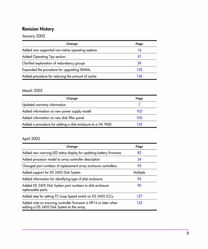
Revision HistoryJanuary 2002
March 2002
April 2002
Change Page
Added new supported non-native operating systems. 16
Added Operating Tips section. 57
Clarified explanation of redundancy groups 39
Expanded the procedure for upgrading DIMMs. 135
Added procedure for reducing the amount of cache. 136
Change Page
Updated warranty information 7
Added information on new power supply model 102
Added information on new disk filler panel. 100
Added a procedure for adding a disk enclosure to a VA 7400. 132
Change Page
Added new warning LED status display for updating battery firmware. 82
Added processor model to array controller description 24
Changed part numbers of replacement array enclosure controllers. 93
Added support for DS 2405 Disk System Multiple
Added information for identifying type of disk enclosure 92
Added DS 2405 Disk System part numbers to disk enclosure replaceable parts.
95
Added step for setting FC Loop Speed switch on DS 2405 LCCs. 127
Added note on ensuring controller firmware is HP14 or later when adding a DS 2405 Disk System to the array.
132
3
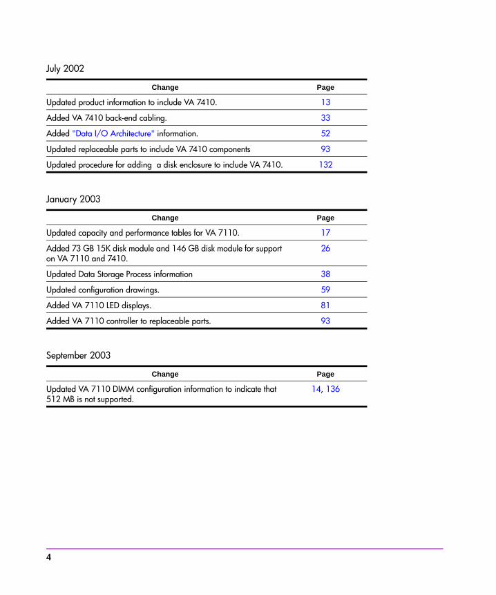
July 2002
January 2003
September 2003
Change Page
Updated product information to include VA 7410. 13
Added VA 7410 back-end cabling. 33
Added "Data I/O Architecture" information. 52
Updated replaceable parts to include VA 7410 components 93
Updated procedure for adding a disk enclosure to include VA 7410. 132
Change Page
Updated capacity and performance tables for VA 7110. 17
Added 73 GB 15K disk module and 146 GB disk module for support on VA 7110 and 7410.
26
Updated Data Storage Process information 38
Updated configuration drawings. 59
Added VA 7110 LED displays. 81
Added VA 7110 controller to replaceable parts. 93
Change Page
Updated VA 7110 DIMM configuration information to indicate that 512 MB is not supported.
14, 136
4
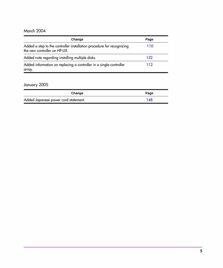
March 2004
January 2005
Change Page
Added a step to the controller installation procedure for recognizing the new controller on HP-UX.
110
Added note regarding installing multiple disks. 132
Added information on replacing a controller in a single-controller array.
112
Change Page
Added Japanese power cord statement. 148
5

About This GuideThis guide is intended for use by information technology (IT), service, and other personnel involved in managing, operating, servicing, and upgrading the HP StorageWorks Virtual Array products. It is organized into the following chapters:
Related Documents and InformationThe following items contain information related to the installation, configuration, and management and of the HP StorageWorks Virtual Array products:
— HP StorageWorks Virtual Array 7000 Family Installation Guide - includes step-by-step instructions for installing and configuring the hardware and software components of the HP StorageWorks Virtual Array products.
— HP StorageWorks Virtual Array Family Rack Installation Guide - includes step-by-step instructions for installing the HP StorageWorks Virtual Array products into HP Rack System/E, HP System racks, and Compaq 9000 racks.
— HP StorageWorks CommandView SDM Installation and User Guide - describes how to install and use the HP StorageWorks CommandView SDM software and its associated utilities to configure, manage, and diagnose problems with the array.
Chapter 1. Product Overview Describes the features, controls, and operation of the disk array.
Chapter 2. System Configurations Guidelines for designing array configurations for different system requirements.
Chapter 3. Troubleshooting Instructions for isolating and solving common problems that may occur during array operation
Chapter 4. Servicing & Upgrading Instructions for removing and replacing all field replaceable units.
Chapter 5. Specifications & Regulatory Statements
Product dimensions, weight, temperature and humidity limits, shock and vibration limits, electrical and power specifications, regulatory and safety statements, and Declaration of Conformity.
6
Warranty Information
Standard Limited Warranty
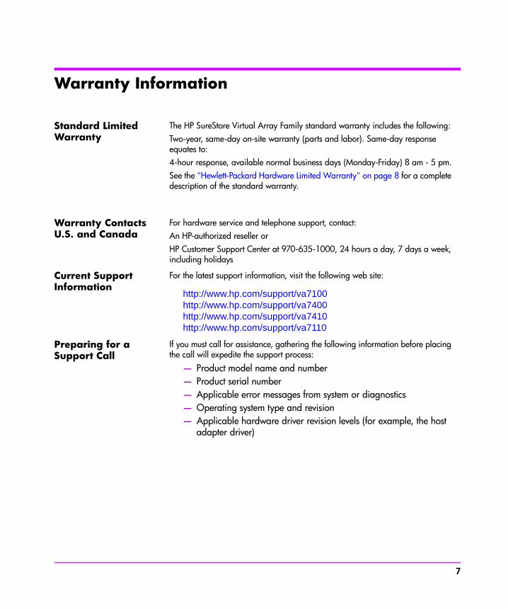
The HP SureStore Virtual Array Family standard warranty includes the following:Two-year, same-day on-site warranty (parts and labor). Same-day response equates to: 4-hour response, available normal business days (Monday-Friday) 8 am - 5 pm.See the "Hewlett-Packard Hardware Limited Warranty" on page 8 for a complete description of the standard warranty.
Warranty ContactsU.S. and Canada
For hardware service and telephone support, contact: An HP-authorized reseller orHP Customer Support Center at 970-635-1000, 24 hours a day, 7 days a week, including holidays
Current Support Information
For the latest support information, visit the following web site:
http://www.hp.com/support/va7100http://www.hp.com/support/va7400http://www.hp.com/support/va7410http://www.hp.com/support/va7110
Preparing for a Support Call
If you must call for assistance, gathering the following information before placing the call will expedite the support process:
— Product model name and number— Product serial number— Applicable error messages from system or diagnostics— Operating system type and revision— Applicable hardware driver revision levels (for example, the host
adapter driver)
7
Hewlett-Packard Hardware Limited WarrantyHP warrants to you, the end-user Customer, that HP SureStore Virtual Array Family hardware components and supplies will be free from defects in material and workmanship under normal use after the date of purchase for two years. If HP or Authorized Reseller receives notice of such defects during the warranty period, HP or Authorized Reseller will, at its option, either repair or replace products that prove to be defective. Replacement parts may be new or equivalent in performance to new.
Should HP or Authorized Reseller be unable to repair or replace the hardware or accessory within a reasonable amount of time, Customer's alternate remedy will be a refund of the purchase price upon return of the HP SureStore Virtual Array Family.
Replacement Parts Warranty
HP replacement parts assume the remaining warranty of the parts they replace. Warranty life of a part is not extended by means of replacement.
Items Not Covered Your HP SureStore Virtual Array Family warranty does not cover the following: — Products purchased from anyone other than HP or an authorized
HP reseller— Non-HP products installed by unauthorized entities— Customer-installed third-party software— Routine cleaning, or normal cosmetic and mechanical wear— Damage caused by misuse, abuse, or neglect— Damage caused by parts that were not manufactured or sold by
HP— Damage caused when warranted parts were repaired or replaced
by an organization other than HP or by a service provider not authorized by HP
8

contents
Warranty Information 6Hewlett-Packard Hardware Limited Warranty 7
1 Product Overview 13Supported Operating Systems 16Array Management Software 16Product Features 17
Controller Enclosure Components 19Array Controller 24Array Controller Filler Panel 26Disk Drives 26Disk Drive Filler Panels 28Power Modules 28
Disk Enclosure Components 29Link Controller Card (VA 7110/7400/7410 Only) 30Disk Drives 30Disk Drive Filler Panels 30Power Modules 34
Operating the Power/Standby Switch 35Power-On Self-Test 36Shutdown 36
Data Storage Process 38Virtual Array 38Redundancy Groups 39Performance Path 45RAID Levels 47
Data I/O Architecture 52Operating Tips 57
9
Automatic Hot Spare Setting Behavior 57Install an Even Number of Disks in Each Redundancy Group 57Auto Rebuild Behavior 58
2 System Configurations 59Lowest Entry Point, Non-HA Minimum Configuration (VA 7100 only) 59Lowest Entry Point, Non-HA Minimum Configuration (VA 7410) 60Entry Level Non-Cluster With Path Redundancy (All VA arrays) 61Entry Level Cluster with Path Redundancy High Availability (VA 7410) 62Midrange Non-Cluster (All VA arrays) 63Midrange Non-Cluster (VA 7410) 64Midrange Non-Cluster with Full Storage Path Redundancy (All VA Arrays) 65Typical Non-Clustered with Path Redundancy (VA 7410) 66Typical Clustered Configuration (All VA models) 67Typical Clustered Configuration (VA 7410) 68HP-UX MC Service Guard or Windows 2000 Cluster (All VA arrays) 69Highly Redundant Cluster (VA 7410) 70Typical Highly Redundant Cluster (All VA models) 71Typical Highly Redundant Cluster (VA 7410) 72
3 Troubleshooting 73Troubleshooting Steps 74Redundant FRUs 75Array State & Status 76
Array Power-On Sequence 77LED Status Indications 78Tools for Checking Array State & Status 85
Array Controller Logs 86Types of Array Controller Logs 86Location of Array Controller Logs 86Checking Array Controller Logs 87
EMS Hardware Monitors (HP-UX Only) 88
10 Contents

4 Servicing & Upgrading 91Field Replaceable Units (FRUs) 92
Identifying FRUs 92Hot Swappable FRUs 97
Controller Enclosure Removal & Installation Procedures 98Disk Drives 98Disk Drive Filler Panels 100Power Modules 102Fiber Optic Cables 104Gigabit Interface Converters 106Array Controllers 107Array Controller Filler Panels 115Array Controller Batteries 117Array Controller DIMMs 120Midplane Assembly 122
Disk Enclosure Removal & Installation Procedures 125Disk Drives 125Disk Drive Filler Panels 125Power Modules 125Link Controller Cards (LCCs) 127Midplane Assembly 131
Upgrading the Array 132Increasing Storage Capacity 132Upgrading Single to Dual Array Controllers 134Upgrading Array Controller DIMMs 135Upgrading Array Controller Firmware 137Upgrading Link Controller Card Firmware 137Upgrading Disk Firmware 138
5 Specifications & Regulatory Statements 139Physical, Electrical & Environmental Specifications 140Regulatory Statements 143
Contents 11

12 Contents

1
Product OverviewThe HP StorageWorks Virtual Arrays are Fibre Channel disk arrays featuring scalability, high performance, and advanced data protection. The VA 7000 Family includes the following models:
■ VA 7100 - an entry level array that includes a single controller enclosure with up to 15 disks.
■ VA 7110 - a medium-capacity array that includes a controller enclosure with up to 15 disks, and supports up to 2 additional external disk enclosures each capable of housing 15 disks.
■ VA 7400 - a high-capacity array that includes a controller enclosure with up to 15 disks, and supports up to 6 additional external disk enclosures each capable of housing 15 disks.
■ VA 7410 - a higher-performance model of the VA 7400 that increases the transfer speed between the array and disk enclosures to 2 Gbits/second, increases the amount of cache to 2 Gbytes, and adds additional host and disk Fibre Channel ports.
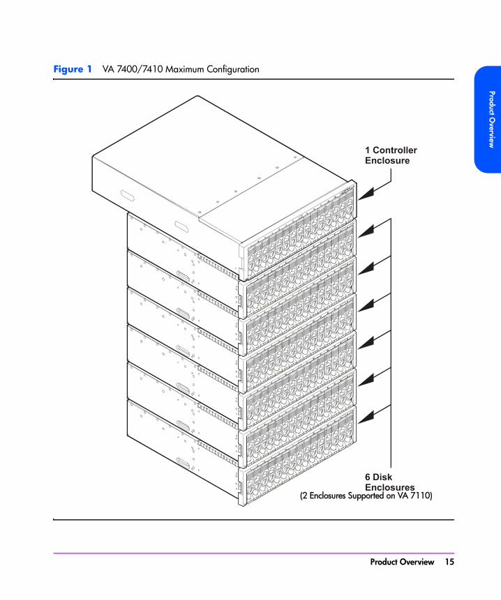
Table 1 lists the VA 7000 Family configurations. Figure 1 illustrates the enclosure configuration for the VA 7400/7410 products.
Both the controller enclosure and the disk enclosure can house up to 15 disk modules in any combination of 18 GB, 36 GB, or 73 GB disk capacities. The VA 7410 and VA 7110 also support 146 GB disk modules. The maximum configuration for a VA 7400/7410 includes 105 disk drives with a total capacity of 7.67 TB. The controller enclosure includes one or two array controllers that use advanced storage technology to automatically select the proper RAID level for storing data.
The array can be connected to one or more hosts, hubs, or switches via fiber optic cables. Factory-racked products are shipped pre-configured in HP Rack
Product Overview 13
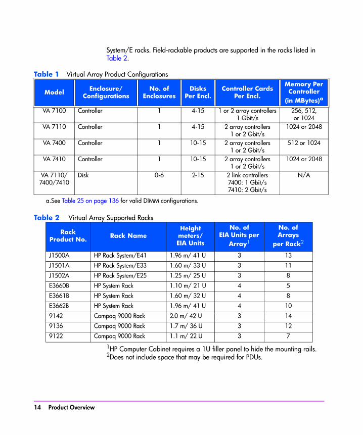
System/E racks. Field-rackable products are supported in the racks listed in Table 2.
Table 1 Virtual Array Product Configurations
Table 2 Virtual Array Supported Racks
1HP Computer Cabinet requires a 1U filler panel to hide the mounting rails.2Does not include space that may be required for PDUs.
Model Enclosure/Configurations
No. ofEnclosures
DisksPer Encl.
Controller CardsPer Encl.
Memory Per Controller
(in MBytes)a
a.See Table 25 on page 136 for valid DIMM configurations.
VA 7100 Controller 1 4-15 1 or 2 array controllers1 Gbit/s
256, 512,or 1024
VA 7110 Controller 1 4-15 2 array controllers1 or 2 Gbit/s
1024 or 2048
VA 7400 Controller 1 10-15 2 array controllers1 or 2 Gbit/s
512 or 1024
VA 7410 Controller 1 10-15 2 array controllers1 or 2 Gbit/s
1024 or 2048
VA 7110/7400/7410
Disk 0-6 2-15 2 link controllers7400: 1 Gbit/s7410: 2 Gbit/s
N/A
RackProduct No. Rack Name
Heightmeters/EIA Units
No. ofEIA Units per
Array1
No. ofArrays
per Rack2
J1500A HP Rack System/E41 1.96 m/ 41 U 3 13
J1501A HP Rack System/E33 1.60 m/ 33 U 3 11
J1502A HP Rack System/E25 1.25 m/ 25 U 3 8
E3660B HP System Rack 1.10 m/ 21 U 4 5
E3661B HP System Rack 1.60 m/ 32 U 4 8
E3662B HP System Rack 1.96 m/ 41 U 4 10
9142 Compaq 9000 Rack 2.0 m/ 42 U 3 14
9136 Compaq 9000 Rack 1.7 m/ 36 U 3 12
9122 Compaq 9000 Rack 1.1 m/ 22 U 3 7
14 Product Overview
Product Overview
Figure 1 VA 7400/7410 Maximum Configuration
(2 Enclosures Supported on VA 7110)
Product Overview 15

Supported Operating Systems
Native Operating SystemsThe arrays are supported on the following native operating systems running CommandView SDM software:
— HP-UX 11.x— Windows NT 4.0— Windows 2000— Red Hat Linux
Non-Native Operating SystemsThe following non-native operating systems are only supported using a dedicated management station running CommandView SDM on one of the native operating systems listed above:
— Sun Solaris— IBM AIX— NetWare— MPE/iX (VA 7100 only)
Array Management SoftwareHP StorageWorks CommandView SDM (Storage Device Manager) software, shipped with the arrays, is used to configure, manage, diagnose, and monitor the performance of the array. The software runs on the native operating systems and includes the following interfaces:
— CommandView Graphical User Interface (GUI)— Command Line User Interface (CLUI)— CommandView User Interface (CVUI)
16 Product Overview

Product Overview
Product FeaturesThe arrays include the following features:
■ Scalability
The capacities for the different products and disk modules are listed in Table 3.
■ High performance
— 10K rpm & 15K rpm disk drives— 1 or 2 Gbit/s native Fibre Channel (host to controllers/controllers to
back-end)— High performance read/write IOPS and cache hits. See Table 4
Table 4 Read/Write & Cache Performance
*RAID 1+0 only**RAID 5DP only
Table 3 Data Storage Scalability
ProductNo.
18 GBDisk Module
36 GBDisk Module
73 GBDisk Module
146 GBDisk Module
VA 7100 72 GB min270 GB max
144 GB min540 GB max
292 GB min1095 GB max
Not supported
VA 7110 72 GB min810 GB max
144 GB min1620 GB max
292 GB min3285 GB max
584 GB min6570 GB max
VA 7400 180 GB min1895 max
360 GB min3780 GB max
730 GB min7665 GB max
Not supported
VA 7410 180 GB min1895 max
360 GB min3780 GB max
730 GB min7665 GB max
1460 GB min15,330 GB max
ProductNo.
RandomReads
RandomWrites
SequentialReads
SequentialWrites
CacheHits
VA 7100 3,200 IOPS*3,000 IOPS**
1,600 IOPS*480 IOPS**
90 MB/s 45 MB/s 14,000 IOPS
VA 7110 7150 IOPS*7100 IOPS**
3500 IOPS*1050 IOPS**
160 MB/s 84 MB/s 15,500 IOPS
VA 7400 8,000 IOPS*7,500 IOPS**
4,000 IOPS*1,200 IOPS**
160 MB/s 80 MB/s 22,500 IOPS
VA 7410 11,000 IOPS*11,000 IOPS**
5,500 IOPS*1,100 IOPS**
330 MB/s 250 MB/s 30,000 IOPS
Product Overview 17
■ Advanced data protection
— RAID 5DP— End-to-end data protection— Mirrored ECC NV-SDRAM1
— Dual battery cache backup— Dual-ported native Fibre Channel disks— Redundant, hot swappable field replaceable components – controllers,
power supplies, cooling, Fibre Channel components 1Non-volatile synchronous dynamic random access memory/Error Correction Code
18 Product Overview
Product Overview
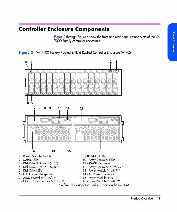
Controller Enclosure ComponentsFigure 2 through Figure 6 show the front and rear panel components of the VA 7000 Family controller enclosures.
Figure 2 VA 7100 Factory-Racked & Field-Racked Controller Enclosure (A/AZ)
*Reference designator used in CommandView SDM
1 - Power/Standby Switch 9 - HOST FC LEDs2 - System LEDs 10 - Array Controller LEDs3 - Disk Drive Slot No. 1 (of 15) 11 - RS-232 Connector4 - Disk Drive 1 (of 15) - M/D1* 12 - Array Controller 2 - M/C2*5 - Disk Drive LEDs 13 - Power Module 1 - M/P1*6 - ESD Ground Receptacle 14 - AC Power Connector7 - Array Controller 1- M/C1* 15 - Power Module LEDs8 - HOST FC Connector - M/C1.H1* 16 - Power Module 2 - M/P2*
2 134
7 8 9 10 11 12
16
56
14 13 15
Product Overview 19
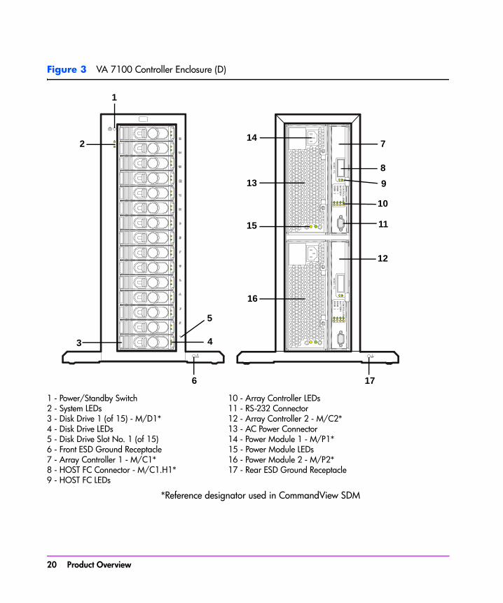
Figure 3 VA 7100 Controller Enclosure (D)
*Reference designator used in CommandView SDM
1 - Power/Standby Switch 10 - Array Controller LEDs2 - System LEDs 11 - RS-232 Connector3 - Disk Drive 1 (of 15) - M/D1* 12 - Array Controller 2 - M/C2*4 - Disk Drive LEDs 13 - AC Power Connector5 - Disk Drive Slot No. 1 (of 15) 14 - Power Module 1 - M/P1*6 - Front ESD Ground Receptacle 15 - Power Module LEDs7 - Array Controller 1 - M/C1* 16 - Power Module 2 - M/P2*8 - HOST FC Connector - M/C1.H1* 17 - Rear ESD Ground Receptacle9 - HOST FC LEDs
1
2
5
6 17
7
10
9
11
12
14
13
15
16
8
43
20 Product Overview
Product Overview
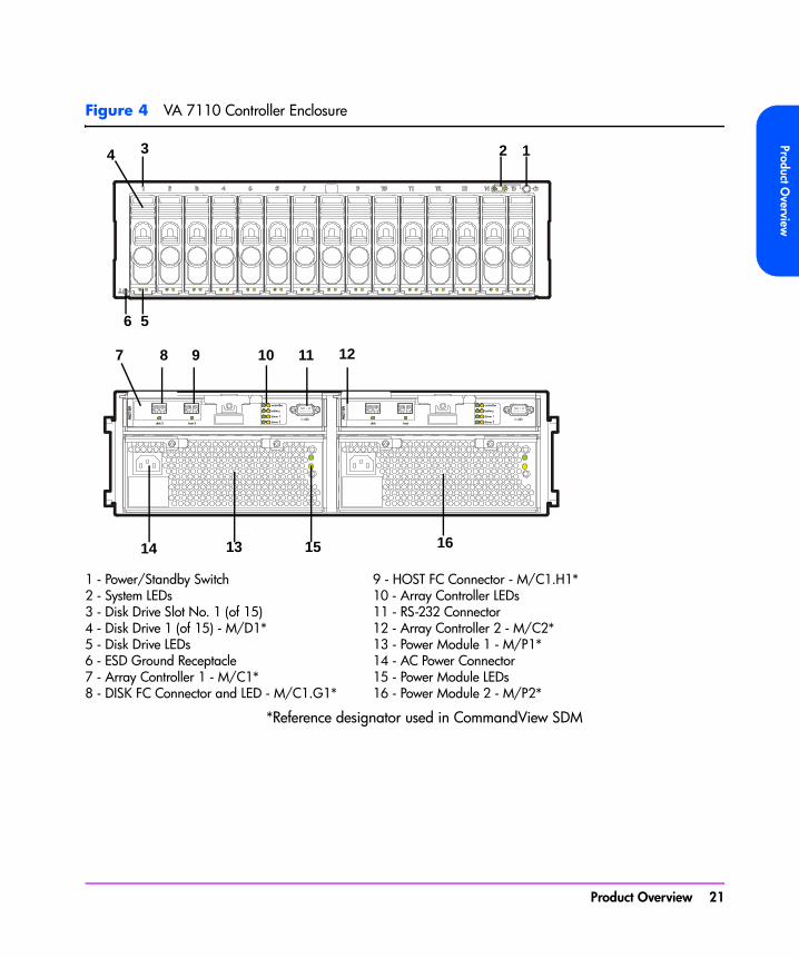
Figure 4 VA 7110 Controller Enclosure
*Reference designator used in CommandView SDM
1 - Power/Standby Switch 9 - HOST FC Connector - M/C1.H1*2 - System LEDs 10 - Array Controller LEDs3 - Disk Drive Slot No. 1 (of 15) 11 - RS-232 Connector4 - Disk Drive 1 (of 15) - M/D1* 12 - Array Controller 2 - M/C2*5 - Disk Drive LEDs 13 - Power Module 1 - M/P1*6 - ESD Ground Receptacle 14 - AC Power Connector7 - Array Controller 1 - M/C1* 15 - Power Module LEDs8 - DISK FC Connector and LED - M/C1.G1* 16 - Power Module 2 - M/P2*
hostdisk
A62
18A
host 2disk 2
A62
18A
1234
6 5
7 8 9 10 11 12
1314 15 16
Product Overview 21

Figure 5 VA 7400 Controller Enclosure
*Reference designator used in CommandView SDM
1 - Power/Standby Switch 10 - HOST FC Connector - M/C1.H1*2 - System LEDs 11 - HOST FC LED3 - Disk Drive Slot No. 1 (of 15) 12 - Array Controller LEDs4 - Disk Drive 1 (of 15) - M/D1* 13 - RS-232 Connector5 - Disk Drive LEDs 14 - Array Controller 2 - M/C2*6 - ESD Ground Receptacle 15 - Power Module 1 - M/P1*7 - Array Controller 1 - M/C1* 16 - AC Power Connector8 - DISK FC LED 17 - Power Module LEDs9 - DISK FC Connector - M/C1.G1* 18 - Power Module 2 - M/P2*
2 134
6 5
16 15 17 18
8 9 12 137 1110 14
22 Product Overview

Product Overview
Figure 6 VA 7410 Controller Enclosure (A/AZ)
*Reference designator used in CommandView SDM
1 - Power/Standby Switch 10 - HOST 1 FC Port and LED (M/C1.H1*)2 - System LEDs 11 - HOST 2 FC Port and LED (M/C1.H2*)3 - Disk Drive Slot No. 1 (of 15) 12 - Array Controller LEDs4 - Disk Drive 1 (of 15) (M/D1*) 13 - RS-232 Connector5 - Disk Drive LEDs 14 - Array Controller 2 (M/C2*)6 - ESD Ground Receptacle 15 - Power Module 1 (M/P1*)7 - Array Controller 1 (M/C1*) 16 - AC Power Connector8 - DISK 1 FC Port and LED (M/C1.J1*) 17 - Power Module LEDs9 - DISK 2 FC Port and LED (M/C1.J2*) 18 - Power Module 2 (M/P2*)
2 134
6 5
16 15 17 18
8 9 12 137 1110 14
Product Overview 23
Array Controller The array controller contains the intelligence and functionality required to manage the operation of the array. Its functions include:
■ Implementing HP AutoRAID™ technology to ensure optimum performance and cost-efficient data storage.
■ Managing all communication between the host and the disk drives via one (single array controller) or two (dual array controller) Fibre Channel arbitrated loops.
■ Maintaining data integrity.
■ Rebuilding the array in the event of a disk failure.
■ Monitoring the operation of all hardware components, including the array controller itself.
In a dual array controller configuration, two controllers provide redundant paths to array data. Dual array controllers operate together in active-active concurrent access mode, allowing a possible increase in I/O performance while providing data redundancy. In active-active mode, memory maps on both controllers are constantly and simultaneously updated. By maintaining a mirror image of the maps, the second controller can take over immediately if the first controller fails.
Each array controller card includes the following components:
— 1 or 2 Dual Inline Memory Modules (DIMMs)— 1 Battery— VA 7100 Only - 1 Gigabit Interface Converter (GBIC)— Motorola 8240 PowerPC processor (VA 7100 and VA 7400)— IBM 440 processor (VA 7410)
VA 7410 Fibre Channel PortsThe VA 7410 enhances flexibility, availability, and performance by adding an additional host port to each controller. This increases the number of paths from the host systems to the array. The VA 7410 also adds a second disk port to each controller, resulting in four back-end ports. This creates two independent Fibre Channel loops between the controller enclosure and the disk enclosures. Back-end performance is enhanced by distributing the disks across both loops.
24 Product Overview
Product Overview
DIMMsEach array controller includes one or two ECC SDRAM DIMMs that are battery backed up and mirrored with the dual controller. This memory is used for the read and write cache, and for the virtualization data structures. These data structures provide the logical-to-physical mapping required for virtualization and are vital to the operation of the array. Without these data structures, all data in the array is inaccessible.
Note The DIMMs are a critical component in maintaining correct operation of the array. Use extreme caution when replacing or modifying the DIMM configuration.
Table 25 on page 136 shows the valid configuration of DIMMs for each controller cache size. In a dual controller configuration, both controllers must have the same cache size.
Battery
Note The array controller battery is a critical component in maintaining the virtualization data structures during a power loss when the array has not successfully completed a shutdown. Exhausting the battery power in this state may result in data loss.
Each array controller includes a Lithium Ion-type battery with a built-in microprocessor. The battery provides backup power to the DIMMs in the event of a power failure or if array power is switched off. The batteries provide power for minimum of 84 hours. If line power is lost, the green BATTERY LED will flash with a 5% duty cycle while powering the DIMMs. A fully charged battery will maintain DIMM memory contents for a minimum of three days. (The three-day specification includes derating for battery life, temperature, and voltage.) If the battery loses its charge, or if it is removed from the controller, the DIMMs will not be powered and memory maps will be lost.
Battery Status. The controller constantly interrogates the battery for its status. If the battery cannot maintain memory contents for a minimum of three days, a warning will notify the operator to replace the battery. Every six months, the battery performs a self-test to determine its charge status. Then it is fully discharged and fully recharged to optimize battery life. This action is not indicated by software or LEDs. In a dual controller configuration, only one battery at a time is discharged and recharged. If the battery becomes discharged during normal operation, the green BATTERY LED will turn off and the amber BATTERY LED will turn on. If the battery has low charge during a
Product Overview 25

power-on self-test, the self-test will halt until the battery is charged to a minimum operating level.
Battery Life. Many factors affect battery life, including length of storage time, length of operating time, storage temperature, and operating temperature. A battery should be replaced if the BATTERY LEDs or the software indicate a battery has diminished storage capacity.
GBIC (VA 7100 Only)A Gigabit Interface Converter (GBIC) is connected to the HOST FC connector on the VA 7100 array controller card. It functions as a fiber optic transceiver, converting data from an electrical to an optical signal in transmit mode, or from an optical signal to an electrical signal in receive mode. On the VA 7400/7410 array controller card, GBIC circuitry is integrated.
Array Controller Filler PanelAn array controller filler panel is used to fill an empty slot in place of an array controller. A filler panel must be installed to maintain proper airflow in the array enclosure.
Caution Do not operate the array for more than 5 minutes with an array controller or filler panel removed. Either an array controller or a filler panel must be installed in the slot to maintain proper airflow in the array enclosure. If necessary, the foam in the replacement array controller packaging can be used to temporarily fill the array controller slot.
Disk DrivesBoth the controller and disk enclosures contain disk drives. Disk drives, or “disks”, provide the storage medium for the virtual array. Four types of native Fibre Channel disk drives are supported in the array; disk capacities can be homogeneous, or can be mixed within the array:
— 18 GB 15K rpm— 36 GB 10K rpm— 36 GB 15K rpm— 73 GB 10K rpm— 73 GB 15K rpm (VA 7110 and VA 7410 only)— 146 GB 10K rpm (VA 7110 and VA 7410 only)
26 Product Overview

Product Overview
A new disk can be added at any time, even while the array is operating. When a disk is replaced, the array applies power to the disk in a controlled manner to eliminate power stresses. The array controller will recognize that a new disk has been added and, if the Auto Include feature is enabled, will include the disk in the array configuration automatically. However, to make the additional capacity available to the host, a new logical drive must be created and configured into the operating system.
A label on the disk drive provides the following information:
— Capacity in gigabytes: 18G, 36G, 73G, or 146G— Interface: FC (Fibre Channel)— Rotational speed in revolutions per minute: 10K or 15K
Note A red zero (0) on the capacity label distinguishes a disk drive filler panel from a disk drive.
Image DisksWhen the array is formatted, the array controller selects two disks as image disks. On the VA 7410 a third disk is identified as a backup in the event one of the primary image disks fails. Because it is not possible to predict which disks will be selected as the image disks, the management software must be used to determine which disks have been selected.
The image disks serve two functions:
■ The image disks have space reserved for copies, or “images”, of the write cache and virtualization data structures stored in the controller NVRAM. During a shutdown, a complete copy of the NVRAM is stored on both image disks. If the maps are lost, they can be restored from the image disks.
■ When resiliency map settings are set to the factory default (Normal Resiliency), changes to the maps, which have occurred since the last shutdown, are updated every 4 seconds on the image disks.
Note A shutdown makes the disk set independent of its controller. Because all of the necessary mapping information is on the image disks, it is possible to install a new controller or move the entire disk set to another controller. The new controller will determine that it has a new disk set, and will logically attach itself to those disks.
Product Overview 27

If an image disk fails on the VA 7100 or VA 7400, the array will operate with a single image disk until the failed disk is replaced. If an image disk fails on the VA 7410, the backup image disk will be used, maintaining image disk redundancy. When the original failed image disk is replaced, it will be assigned the role of backup image disk.
Disk Drive Filler PanelsDisk drive filler panels are used in both the controller and disk enclosures to fill empty slots in place of disk drives. A filler panel must be installed to maintain proper cooling in the enclosure.
Caution Do not operate the array for more than 5 minutes with a disk drive or filler panel removed. Either a disk drive or filler panel must be installed in the slot to maintain proper airflow and avoid overheating.
Power ModulesThe controller enclosure is shipped with two fully redundant power modules. Each power module contains:
■ An autoranging power supply that converts ac input power to dc output power for use by the other array components. The power supplies share the power load under non-fault conditions. If one power supply fails, the other supply delivers the entire load to maintain power for the array. Each power supply uses a separate power cord. Both power supplies can be plugged into a common ac power source, or each supply can be plugged into a separate ac circuit to provide power source redundancy.
■ Two internal blowers, which provide airflow and maintain the proper operating temperature within the enclosure. If a blower fails, a fault will occur. The other power module will continue to operate and its blowers will continue to cool the enclosure. Even if a power supply fails, both of the blowers within the power module will continue to operate; dc power for the blowers is distributed from the midplane.
28 Product Overview
Product Overview
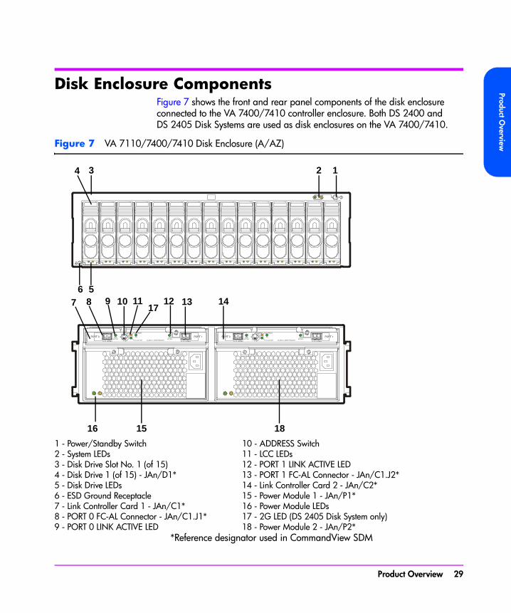
Disk Enclosure ComponentsFigure 7 shows the front and rear panel components of the disk enclosure connected to the VA 7400/7410 controller enclosure. Both DS 2400 and DS 2405 Disk Systems are used as disk enclosures on the VA 7400/7410.
Figure 7 VA 7110/7400/7410 Disk Enclosure (A/AZ)
*Reference designator used in CommandView SDM
1 - Power/Standby Switch 10 - ADDRESS Switch2 - System LEDs 11 - LCC LEDs3 - Disk Drive Slot No. 1 (of 15) 12 - PORT 1 LINK ACTIVE LED4 - Disk Drive 1 (of 15) - JAn/D1* 13 - PORT 1 FC-AL Connector - JAn/C1.J2*5 - Disk Drive LEDs 14 - Link Controller Card 2 - JAn/C2*6 - ESD Ground Receptacle 15 - Power Module 1 - JAn/P1*7 - Link Controller Card 1 - JAn/C1* 16 - Power Module LEDs8 - PORT 0 FC-AL Connector - JAn/C1.J1* 17 - 2G LED (DS 2405 Disk System only)9 - PORT 0 LINK ACTIVE LED 18 - Power Module 2 - JAn/P2*
1234
5698 10 11
16 15 18
7 12 13 1417
Product Overview 29

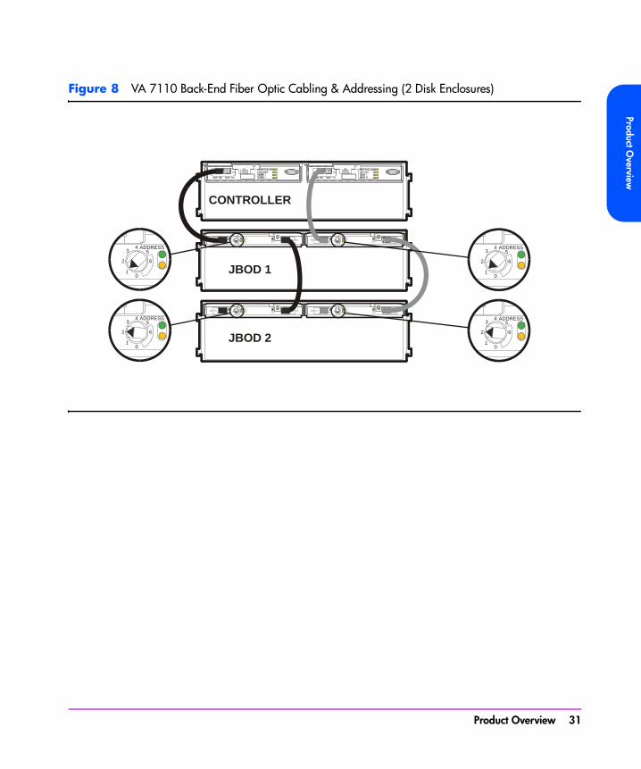
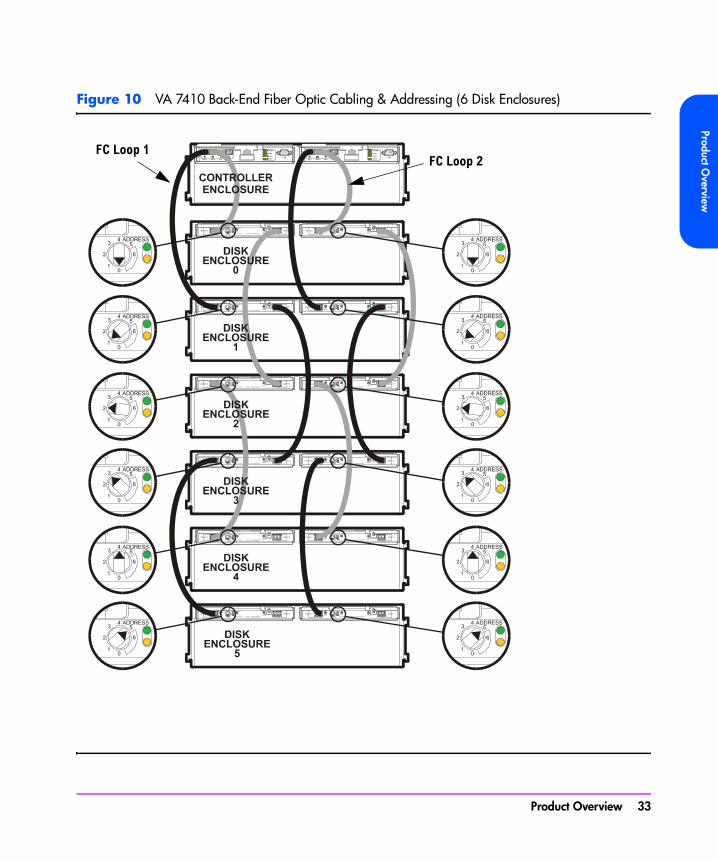
Link Controller Card (VA 7110/7400/7410 Only)The link controller card (LCC) functions as a fiber optic transceiver for the disk enclosure. It allows up to six disk enclosures to be connected to the controller enclosure. Each LCC includes a Fibre Channel address switch, used to set the Fibre Channel loop address of the card. Each disk enclosure must have a unique address and both LCCs in a disk enclosure must be set to the same address. For cabling connections and switch settings, see Figure 8 for the VA 7110, Figure 9 for the VA 7400, and Figure 10 for the VA 7410.
The LCC also monitors the operation of the disk enclosure and provides status information to the array controller. This includes what disks are present and their status, power supply status, and notification if the enclosure operating temperature has exceeded its limits.
Disk DrivesUp to 15 disks can be installed in each disk enclosure. The controller enclosure and the disk enclosure both use the same disk drives. See "Disk Drives" on page 26.
Image DisksThe image disks can be located in either the controller enclosure or the disk enclosure. See "Image Disks" on page 27.
Disk Drive Filler PanelsThe controller enclosure and the disk enclosure both use the same disk drive filler panels. See "Disk Drive Filler Panels" on page 28.
30 Product Overview
Product Overview
Figure 8 VA 7110 Back-End Fiber Optic Cabling & Addressing (2 Disk Enclosures)
PORT 0 PORT 1
ADDRESS43
2
10
6
5
FC-AL 100MB/s FC-AL 100MB/s
LINKACTIVE
LINKACTIVE
LCCACTIVE
LCCFAULT
A62
14-6
0001
PORT 0 PORT 1
ADDRESS43
2
10
6
5
FC-AL 100MB/s FC-AL 100MB/s
LINKACTIVE
LINKACTIVE
LCCACTIVE
LCCFAULT
A62
14-6
0001
PORT 0 PORT 1
ADDRESS43
2
10
6
5
FC-AL 100MB/s FC-AL 100MB/s
LINKACTIVE
LINKACTIVE
LCCACTIVE
LCCFAULT
A621
4-60
001
PORT 0 PORT 1
ADDRESS43
2
10
6
5
FC-AL 100MB/s FC-AL 100MB/s
LINKACTIVE
LINKACTIVE
LCCACTIVE
LCCFAULT
A621
4-60
001
ADDRESS43
2
10
6
5
ADDRESS43
2
10
6
5
ADDRESS43
2
10
6
5
ADDRESS43
2
10
6
5
CONTROLLER
JBOD 1
JBOD 2
Product Overview 31
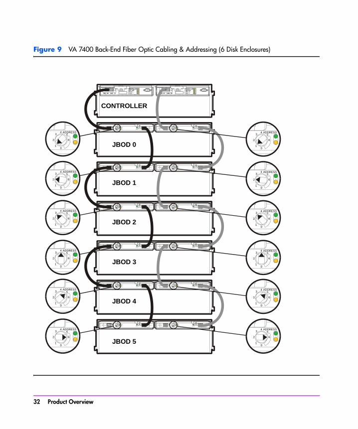
Figure 9 VA 7400 Back-End Fiber Optic Cabling & Addressing (6 Disk Enclosures)
PORT 0 PORT 1
ADDRESS43
2
10
6
5
FC-AL 100MB/s FC-AL 100MB/s
LINKACTIVE
LINKACTIVE
LCCACTIVE
LCCFAULT
A62
14-6
0001
PORT 0 PORT 1
ADDRESS43
2
10
6
5
FC-AL 100MB/s FC-AL 100MB/s
LINKACTIVE
LINKACTIVE
LCCACTIVE
LCCFAULT
A62
14-6
0001
PORT 0 PORT 1
ADDRESS43
2
10
6
5
FC-AL 100MB/s FC-AL 100MB/s
LINKACTIVE
LINKACTIVE
LCCACTIVE
LCCFAULT
A62
14-6
0001
PORT 0 PORT 1
ADDRESS43
2
10
6
5
FC-AL 100MB/s FC-AL 100MB/s
LINKACTIVE
LINKACTIVE
LCCACTIVE
LCCFAULT
A62
14-6
0001
PORT 0 PORT 1
ADDRESS43
2
10
6
5
FC-AL 100MB/s FC-AL 100MB/s
LINKACTIVE
LINKACTIVE
LCCACTIVE
LCCFAULT
A62
14-6
0001
PORT 0 PORT 1
ADDRESS43
2
10
6
5
FC-AL 100MB/s FC-AL 100MB/s
LINKACTIVE
LINKACTIVE
LCCACTIVE
LCCFAULT
A62
14-6
0001
PORT 0 PORT 1
ADDRESS43
2
10
6
5
FC-AL 100MB/s FC-AL 100MB/s
LINKACTIVE
LINKACTIVE
LCCACTIVE
LCCFAULT
A62
14-6
0001
PORT 0 PORT 1
ADDRESS43
2
10
6
5
FC-AL 100MB/s FC-AL 100MB/s
LINKACTIVE
LINKACTIVE
LCCACTIVE
LCCFAULT
A62
14-6
0001
PORT 0 PORT 1
ADDRESS43
2
10
6
5
FC-AL 100MB/s FC-AL 100MB/s
LINKACTIVE
LINKACTIVE
LCCACTIVE
LCCFAULT
A62
14-6
0001
PORT 0 PORT 1
ADDRESS43
2
10
6
5
FC-AL 100MB/s FC-AL 100MB/s
LINKACTIVE
LINKACTIVE
LCCACTIVE
LCCFAULT
A62
14-6
0001
PORT 0 PORT 1
ADDRESS43
2
10
6
5
FC-AL 100MB/s FC-AL 100MB/s
LINKACTIVE
LINKACTIVE
LCCACTIVE
LCCFAULT
A62
14-6
0001
PORT 0 PORT 1
ADDRESS43
2
10
6
5
FC-AL 100MB/s FC-AL 100MB/s
LINKACTIVE
LINKACTIVE
LCCACTIVE
LCCFAULT
A62
14-6
0001
ADDRESS43
2
10
6
5
ADDRESS43
2
10
6
5
ADDRESS43
2
10
6
5
ADDRESS43
2
10
6
5
ADDRESS43
2
10
6
5
ADDRESS43
2
10
6
5
ADDRESS43
2
10
6
5
ADDRESS43
2
10
6
5
ADDRESS43
2
10
6
5
ADDRESS43
2
10
6
5
ADDRESS43
2
10
6
5
ADDRESS43
2
10
6
5
CONTROLLER
JBOD 0
JBOD 1
JBOD 2
JBOD 3
JBOD 4
JBOD 5
32 Product Overview
Product Overview
Figure 10 VA 7410 Back-End Fiber Optic Cabling & Addressing (6 Disk Enclosures)
FC Loop 1FC Loop 2
Product Overview 33
Power ModulesThe disk enclosure is shipped with two fully redundant power modules. Each power module contains:
■ An autoranging power supply that converts ac input power to dc output power for use by the other array components. The power supplies share the power load under non-fault conditions. If one power supply fails, the other supply delivers the entire load to maintain power for the array. Each power supply uses a separate power cord. Both power supplies can be plugged into a common power source, or each supply can be plugged into a separate circuit to provide power source redundancy.
■ One internal blower, which provides airflow and maintains the proper operating temperature within the array enclosure. If the blower fails, a fault will occur. The other power module will continue to operate and its blower will continue to cool the enclosure. Even if a power supply fails, the blower within the power module will continue to operate; dc power for the blower is distributed from the midplane.
34 Product Overview
Product Overview
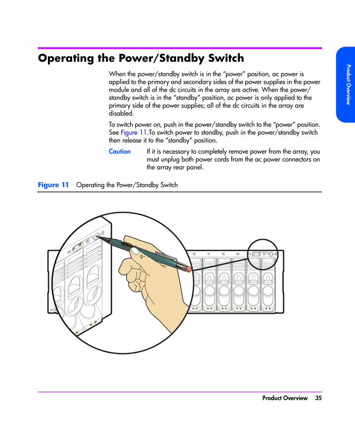
Operating the Power/Standby SwitchWhen the power/standby switch is in the “power” position, ac power is applied to the primary and secondary sides of the power supplies in the power module and all of the dc circuits in the array are active. When the power/standby switch is in the “standby” position, ac power is only applied to the primary side of the power supplies; all of the dc circuits in the array are disabled.
To switch power on, push in the power/standby switch to the “power” position. See Figure 11.To switch power to standby, push in the power/standby switch then release it to the “standby” position.
Caution If it is necessary to completely remove power from the array, you must unplug both power cords from the ac power connectors on the array rear panel.
Figure 11 Operating the Power/Standby Switch
Product Overview 35
Power-On Self-TestImmediately after the array is powered on, the controller enclosure and disk enclosures (VA 7400/7410 only) perform a power-on self-test.
During a power-on self-test, you will see the following front panel activity:
■ The system power/activity LED turns on solid green.
■ The disk drive activity LEDs flash while the controller establishes communication with the drives, then two LEDs at a time turn on solid green, one from the lower disk drive slots (1-8) and one from the upper disk drive slots (9-15), while the associated drives spin up.
When the power-on self-test completes successfully:
■ All LEDs on the front panel should be solid green.
ShutdownThe coordinated shutdown process is used to take the array offline. The primary function of shutdown is to copy the contents of the NVRAM to the image disks. This protects the array against data loss if a battery fails in the absence of ac power. In the shutdown state, the array can still respond to management commands from the host, but the host cannot access any of the data in the array.
During shutdown, the array will use the contents of the controller NVRAM if valid. For a dual controller configuration only a single NVRAM image is required to be valid.
Note If the NVRAM image is not valid the array will enter an error state. The configuration information and the write cache have been lost. Access to the data requires a Recover process. Recovery will attempt to recover the configuration information from the data disks. The contents of the write cache are not recoverable.
A shutdown is automatically initiated in two ways:
■ By moving the power/standby switch to the standby position.
■ Using the array management software.
36 Product Overview

Product Overview
Note Using software to perform a shutdown is the preferred method because confirmation of a successful shutdown is reported to the operator.
If the power fails or if you unplug the power cords without performing a shutdown, the following sequence will occur when the array is powered on again:
1 The array will attempt to retrieve the maps from cache and determine if they are valid.
2 If the maps are not valid, the array will retrieve the maps from the image disks.
Note If power to the array is lost by any means other than by moving the power/standby switch to the standby position, the array will not have time to perform a successful shutdown. In this case, a fully charged battery can sustain NVSDRAM contents for 3 days.
Product Overview 37
Data Storage Process
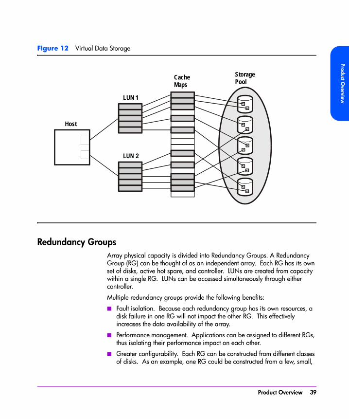
Virtual ArrayThe term “Virtual Array” refers to the way the array manages the disks as a pool of data storage blocks instead of whole physical disks. Like other virtualization within computer systems, this virtualization greatly simplifies the management of the array. Internally, the array uses sophisticated data structures to manage the logical-to-physical address translation. These data structures, often referred to as the “maps”, are key to the operation of the array. See Figure 12.
Administrators’ manage the capacity of the array using Redundancy Groups and LUNs. Each disk belongs to a predefined Redundancy Group, and a LUN is created from the capacity of a Redundancy Group. This is similar to traditional arrays. The virtualization eliminates the need to manage the lower level details. Redundancy Groups can be constructed from any number or capacity of supported disks. Any number of disks can be added to a Redundancy Group at any time. LUNs can be of any size up to the available capacity of a RAID Group, or created and deleted without the knowledge of the underlying physical disk layout. The VA 7100 supports up to 128 LUNs; the VA 7400/7410 support up to 1024 LUNs.
38 Product Overview
Product Overview
Figure 12 Virtual Data Storage
Redundancy GroupsArray physical capacity is divided into Redundancy Groups. A Redundancy Group (RG) can be thought of as an independent array. Each RG has its own set of disks, active hot spare, and controller. LUNs are created from capacity within a single RG. LUNs can be accessed simultaneously through either controller.
Multiple redundancy groups provide the following benefits:
■ Fault isolation. Because each redundancy group has its own resources, a disk failure in one RG will not impact the other RG. This effectively increases the data availability of the array.
■ Performance management. Applications can be assigned to different RGs, thus isolating their performance impact on each other.
■ Greater configurability. Each RG can be constructed from different classes of disks. As an example, one RG could be constructed from a few, small,
Host
LUN 1
LUN 2
CacheMaps
StoragePool
Product Overview 39
high-performance disks, and the other RG from large, slower, high-capacity disks.
The VA 7100 and VA 7400/7410 differ in their implementation of redundancy groups.
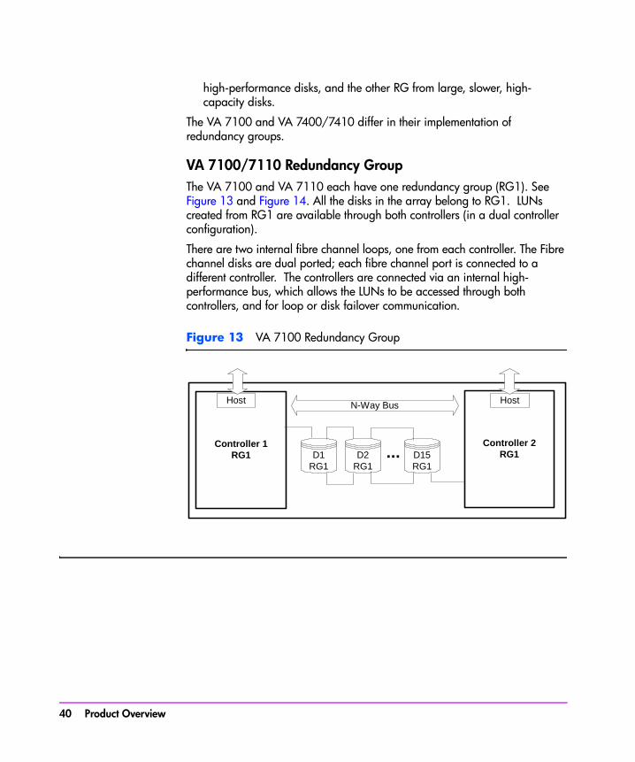
VA 7100/7110 Redundancy GroupThe VA 7100 and VA 7110 each have one redundancy group (RG1). See Figure 13 and Figure 14. All the disks in the array belong to RG1. LUNs created from RG1 are available through both controllers (in a dual controller configuration).
There are two internal fibre channel loops, one from each controller. The Fibre channel disks are dual ported; each fibre channel port is connected to a different controller. The controllers are connected via an internal high-performance bus, which allows the LUNs to be accessed through both controllers, and for loop or disk failover communication.
Figure 13 VA 7100 Redundancy Group
Controller 1RG1
Host
Controller 2RG1
HostN-Way Bus
D2RG1
D15RG1
...D1RG1
40 Product Overview

Product Overview
Figure 14 VA 7110 Redundancy Group
LCC1
D2RG1
LCC2
D15RG1
...D1RG1
LCC1
D2RG1
LCC2
D15RG1
...D1RG1
D2RG1
D15RG1
...Controller 1RG1
Host
Disk
Controller 2RG1
Host
Disk
D1RG1
N-Way Bus
Product Overview 41

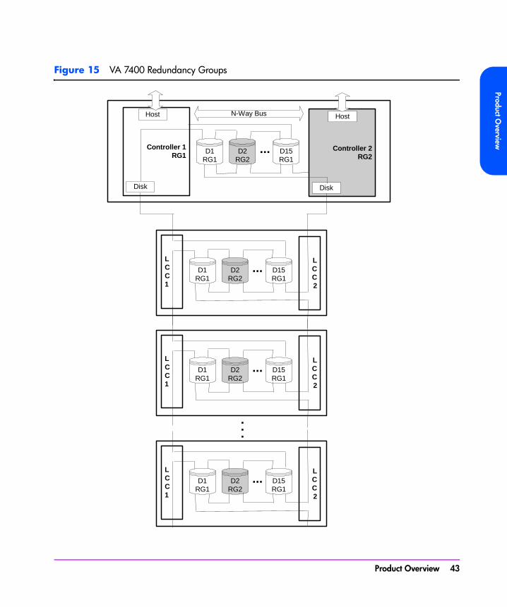
VA 7400/7410 Redundancy GroupsThe VA 7400 and VA 7410 have two redundancy groups (RG1 and RG2). See Figure 15 and Figure 16.
■ Controller 1 manages Redundancy Group 1 (RG1), which consists of all disks in odd numbered slots (D1, D3, D5, D7, D9, D11, D13, D15) in the controller enclosure, and in all disk enclosures (JA0-JA5).
■ Controller 2 manages Redundancy Group 2 (RG2), which consists of all disks in even numbered slots (D2, D4, D6, D8, D10, D12, D14) in the controller enclosure, and in all disk enclosures (JA0-JA5).
On the VA 7410, Redundancy Group are independent of both back-end FC loops. Management of the redundancy group disks is independent of which disk enclosure LCC the array controller is connected to. For example, array controller 1 can be connected to LCC 1 or LCC 2 and it will still manage the disks in the odd numbered slots.
The array controllers are connected via an internal N-Way bus, which used for controller-to-controller communication and loop failover.
42 Product Overview
Product Overview
Figure 15 VA 7400 Redundancy Groups
LCC1
D2RG2
LCC2
D15RG1
...D1RG1
LCC1
D2RG2
LCC2
D15RG1
...D1RG1
LCC1
D2RG2
LCC2
D15RG1
...D1RG1
D2RG2
D15RG1
...Controller 1RG1
Host
Disk
Controller 2RG2
Host
Disk
D1RG1
. . .
N-Way Bus
Product Overview 43
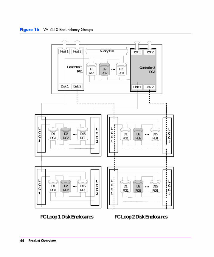
Figure 16 VA 7410 Redundancy Groups
LCC1
D2RG2
LCC2
D15RG1
...D1RG1
LCC1
D2RG2
LCC2
D15RG1
...D1RG1
LCC1
D2RG2
LCC2
D15RG1
...D1RG1
LCC1
D2RG2
LCC2
D15RG1
...D1RG1
FC Loop 1 Disk Enclosures FC Loop 2 Disk Enclosures
D2RG2
D15RG1
...Controller 1RG1
Host 2Host 1
Disk 1 Disk 2
Controller 2RG2
Host 2Host 1
Disk 1 Disk 2
D1RG1
N-Way Bus
44 Product Overview

Product Overview
Performance PathThe performance path is the most direct path from the host to the data in the array. It is specified by two separate device files that direct the data either through Controller 1 or through Controller 2. The performance path is always the faster path in terms of data transfer rate.
Because the array has two active controllers, the host will typically have two paths to data, as shown in Figure 17.
■ The primary path is through the controller which owns the LUN being accessed. That is, the controller that manages the RG the LUN belongs to. On the VA 7400 and 7410 each LUN is assigned to RG1 or RG2, managed by controller 1 and controller 2 respectively. When accessing data on a LUN, the host should send I/Os to the controller which owns the LUN.
■ The secondary path is through the controller which does not own the LUN being accessed. In this situation, the non-owning controller must use the internal N-Way bus to send the I/O to the controller that owns the LUN. Whenever the secondary path is used, I/O performance is impacted due to the inter-controller communication required.
System and SAN configuration with the knowledge of the performance path is a technique to maximize the array performance. For normal workloads this provides very little performance improvements, but for benchmarking and highly utilized arrays, this can provide modest performance gains. The biggest gains can be found with the VA 7100/7400, improvements with the VA 7110/7410 have reduced the performance gained through performance path management.
The use of load balancing software in normal workloads, such as HP AutoPath, can, in many cases, offset any gains in performance by managing the configuration of the performance path.
VA 7100/7110 Performance PathIn the VA 7100, the performance path is always specified by the device file for Controller 1. Because the VA 7100 has only one redundancy group, and the secondary controller is recommended only for failover, the primary controller is always the most direct path to the data. If Controller 1 fails, the host should use the secondary path to Controller 2.
Product Overview 45

VA 7400/7410 Performance PathThe following example illustrates how the performance path is used in a VA 7400/7410:
Assume LUN 4 is part of Redundancy Group 2 under Controller 2. An HP-UX host has two device files that have two separate paths to LUN 4: The primary device file that addresses Controller 2, and the secondary device file that addresses Controller 1. The performance path uses the primary device file, because Controller 2 owns LUN 2. The non-performance path uses the secondary device file. If the secondary device file is used, data flows through Controller 1, across the N-way bus to Controller 2, and then to LUN 2 and its associated disk drives.
Figure 17 Data Paths on the VA 7400/7410
VA 7400/7410
Controller 1
LUN 4 onRG 1
Controller 2
Primary path
Host
Secondary path
46 Product Overview
Product Overview
RAID LevelsRedundant Array of Inexpensive Disks (RAID) technology uses different industry-standard techniques for storing data and maintaining data redundancy. These techniques, called “RAID levels”, define the method used for distributing data on the disks in a logical unit (LUN). LUNs that use different RAID levels can be created in the same array.
The virtual array can be operated in RAID 1+0 level or AutoRAID level, which is a combination of RAID 1+0 and RAID 5DP. The RAID level selected is influenced by factors such as capacity demands and performance requirements. Once a RAID level is selected, it is used for the entire array.
Changing the RAID Level of the Array
The RAID level for the array is established during installation. It is possible to change the RAID level after installation. The steps involved in changing the RAID level depend on which mode you are changing to.
■ Changing from RAID 1+0 to AutoRAID. The RAID level can be changed from RAID 1+0 to AutoRAID on-line. However, it is recommended that you backup all data on the array before changing the RAID level.
■ Changing from AutoRAID to RAID 1+0. The RAID level cannot be changed from AutoRAID to RAID 1+0 on-line. This change requires a complete reformat of the entire array, which will destroy all data on the array. Before changing from AutoRAID to RAID 1+0, backup all data on the array for restoration after the format and RAID change are complete.
RAID 1+0RAID 1+0 provides data redundancy and good performance. However, the performance is achieved by using a less efficient technique of storing redundant data called “mirroring”. Mirroring maintains two copies of the data on separate disks. Therefore, half of the disk space is consumed by redundant data — the “mirror”. RAID 1+0 also stripes the mirrored data segments across all the disks in a RAID Group. A read can use either copy of the data; a write operation must update both copies of the data.
Figure 18 is an example showing the distribution of the two copies of data in a RAID 1+0 configuration. This example shows one RAID Group with 10 data segments, each data segment has an associated mirror segment. After a single disk failure, the copy of a segment is always is available on another disk — this disk(s) is referred to as the “adjacent disk(s)”. The array will continue operation without data loss in the event of any non-adjacent disk failure.
Product Overview 47
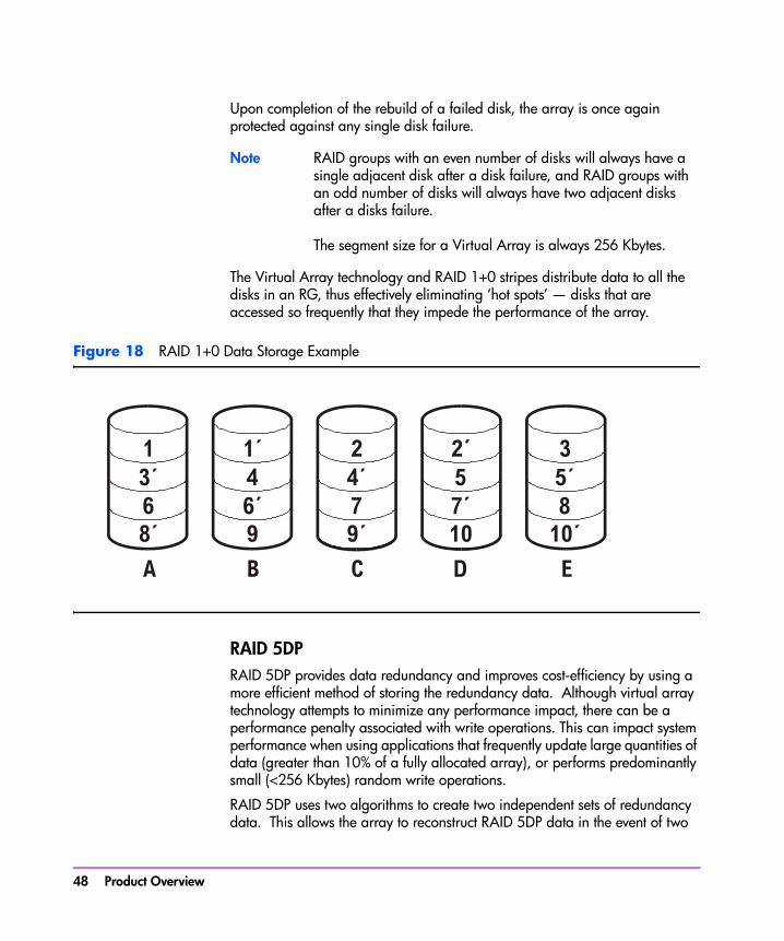
Upon completion of the rebuild of a failed disk, the array is once again protected against any single disk failure.
Note RAID groups with an even number of disks will always have a single adjacent disk after a disk failure, and RAID groups with an odd number of disks will always have two adjacent disks after a disks failure.
The segment size for a Virtual Array is always 256 Kbytes.
The Virtual Array technology and RAID 1+0 stripes distribute data to all the disks in an RG, thus effectively eliminating ‘hot spots’ — disks that are accessed so frequently that they impede the performance of the array.
Figure 18 RAID 1+0 Data Storage Example
RAID 5DPRAID 5DP provides data redundancy and improves cost-efficiency by using a more efficient method of storing the redundancy data. Although virtual array technology attempts to minimize any performance impact, there can be a performance penalty associated with write operations. This can impact system performance when using applications that frequently update large quantities of data (greater than 10% of a fully allocated array), or performs predominantly small (<256 Kbytes) random write operations.
RAID 5DP uses two algorithms to create two independent sets of redundancy data. This allows the array to reconstruct RAID 5DP data in the event of two
48 Product Overview
Product Overview
simultaneous disk failures. The two redundancy segments are referred to as “P” and “Q” parity. P, like traditional RAID 5 arrays, uses an XOR (parity) algorithm. P parity is based on Reed-Solomon ECC technology, similar to error detection and correction found in ECC DRAM.
Application data, and the P and Q parity data, rotate to different disks for each stripe in a RAID Group. Like RAID 1+0, this effectively eliminates hot spots.
A read operation only requires a single access to the disk(s) containing the data, a small (<256 Kbytes) write operation requires that the data, and the P and Q parity data be updated – this is the source of the small random write performance impact. For larger (>256 Kbytes) write operations, the Virtual Array implements a log-structured RAID 5DP write. Log-structured writes effectively eliminate the read-modify-write associated with small block writes to RAID 5DP by redirected the write operation to a new RAID 5DP stripe. The P and Q parity data is held in non-volatile write cache until the whole stripe is written, then the P and Q are written. Thus the P and the Q are written only once for each stripe.
Note Until a rebuild is complete, the array is operating in a degraded mode. In degraded mode, the array will use P and/or Q parity to reconstruct data that resided on the failed disk.
Figure 19 is an example showing the distribution of user data and parity data in a RAID 5DP configuration. The example shows one RAID group with five stripes: three data segments and two parity segments (P and Q). The segments are striped across the disks in a rotating fashion. Note that any two disks can fail, but the data, P, or the Q parity is always available to complete a read operation.
Product Overview 49
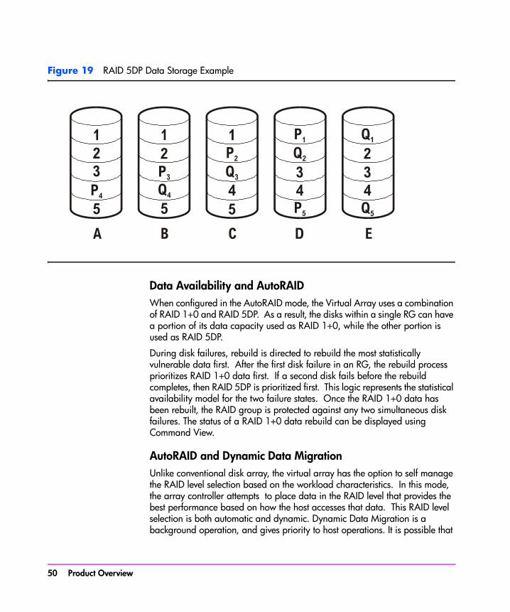
Figure 19 RAID 5DP Data Storage Example
Data Availability and AutoRAIDWhen configured in the AutoRAID mode, the Virtual Array uses a combination of RAID 1+0 and RAID 5DP. As a result, the disks within a single RG can have a portion of its data capacity used as RAID 1+0, while the other portion is used as RAID 5DP.
During disk failures, rebuild is directed to rebuild the most statistically vulnerable data first. After the first disk failure in an RG, the rebuild process prioritizes RAID 1+0 data first. If a second disk fails before the rebuild completes, then RAID 5DP is prioritized first. This logic represents the statistical availability model for the two failure states. Once the RAID 1+0 data has been rebuilt, the RAID group is protected against any two simultaneous disk failures. The status of a RAID 1+0 data rebuild can be displayed using Command View.
AutoRAID and Dynamic Data MigrationUnlike conventional disk array, the virtual array has the option to self manage the RAID level selection based on the workload characteristics. In this mode, the array controller attempts to place data in the RAID level that provides the best performance based on how the host accesses that data. This RAID level selection is both automatic and dynamic. Dynamic Data Migration is a background operation, and gives priority to host operations. It is possible that
50 Product Overview
Product Overview
continuous high demand from the host will preempt all data migration activities.
AutoRAID manages the data placement to the individual 256 K-block. Each LUN is divided into 256 K-blocks call clusters. A cluster can be stored in either RAID 1+0 or RAID 5DP format. The virtualization data structures manage the translation of the logical address (LUN) and the physical location.
The controller is programmed to manage cluster placement. It uses well-known logic, or rules, about RAID level performance characteristics and storage efficiency. This logic directs data that is frequently modified by small transactions to RAID 1+0 storage. Data that is infrequently written, or data that is written sequentially, is directed to RAID 5DP storage.
The behavior is similar to other hierarchical memory systems, such as data caches or Hierarchical Storage Mangers. AutoRAID, like these other systems, provide the performance approaching the highest level of the memory hierarchy, at the cost of the lowest level in the hierarchy.
The controller provides information about data placement and data migration through the Command View performance log. These logs provide details about the storage level for each LUN, and any active migration the array has performed.
End-to-End Data ProtectionEnd-to-end data protection is a process within the array controller to validate the integrity of the data stored on the array. This process is in addition to the normal data checking provided by the disk drives. During a write operation, as data enters the array controller from the host, the controller appends 8 bytes of additional information to each 512-sector. This additional information includes both a checksum and the logical address of the data. To accommodate this additional information, the disks have been reformatted to 520-byte sectors.
During a read operation, as the data is returned to the host, the check information is verified for correctness. An error in the check information will cause the controller to recover the data using the RAID redundancy information. If the recovery is unsuccessful, the transaction is marked unrecoverable, and the array continues to process other host request.
Product Overview 51

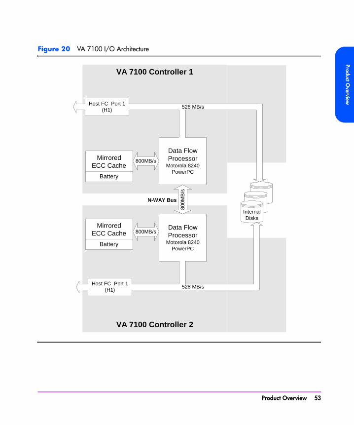
Data I/O ArchitectureThe internal architecture of the array controllers is designed to optimize the speed of data transfer between the array and the host. The internal architecture for each product is illustrated in Figures 20, 22, and 23.
The following major components are involved in the flow of data through the array:
■ Data flow processor - manages movement of data over the internal high-speed busses. The processor also manages the flow of data into and out of the ECC cache.
■ ECC cache - provides temporary storage of data for high-speed access.
■ High-speed busses - provide the data path from the host to the disk media. The N-Way bus provides the communication link between controllers for management and redundancy.
■ FC ports - provide the interface to the host and the back-end disk enclosures. The VA 7410 includes additional FC ports for added flexibility and performance.
52 Product Overview
Product Overview
Figure 20 VA 7100 I/O Architecture
VA 7100 Controller 2
VA 7100 Controller 1
Data FlowProcessor
Motorola 8240PowerPC
MirroredECC Cache
Battery
800MB/s
Data FlowProcessor
Motorola 8240PowerPC
MirroredECC Cache
Battery
800MB/s
800M
B/s
InternalDisks
N-WAY Bus
Host FC Port 1(H1)
Host FC Port 1(H1)
528 MB/s
528 MB/s
Product Overview 53
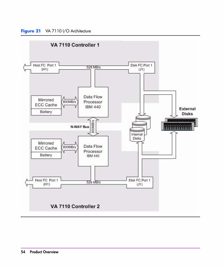
Figure 21 VA 7110 I/O Architecture
54 Product Overview

Product Overview
Figure 22 VA 7400 I/O Architecture
VA 7400 Controller 2
VA 7400 Controller 1
Data FlowProcessor
Motorola 8240PowerPC
Disk FC Port 1(J1)
MirroredECC Cache
Battery
800MB/s
Data FlowProcessor
Motorola 8240PowerPC
Disk FC Port 1(J1)
MirroredECC Cache
Battery
800MB/s
800M
B/s
InternalDisks
1 2 3 4 5 6 7 9 10 11 12 13 14 15
1 2 3 4 5 6 7 9 10 11 12 13 14 15
ExternalDisks
N-WAY Bus
Host FC Port 1(H1)
Host FC Port 1(H1)
528 MB/s
528 MB/s
Product Overview 55
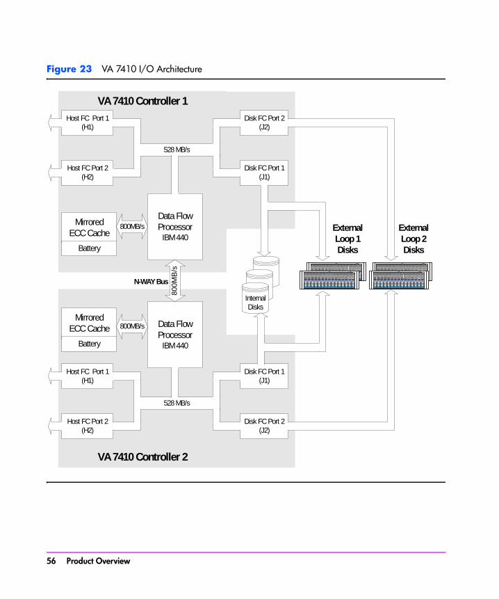
Figure 23 VA 7410 I/O Architecture
VA 7410 Controller 2
VA 7410 Controller 1
Data FlowProcessorIBM 440
Host FC Port 1(H1)
Host FC Port 2(H2)
Disk FC Port 2(J2)
Disk FC Port 1(J1)
528 MB/s
MirroredECC Cache
Battery
800MB/s
Data FlowProcessorIBM 440
Host FC Port 1(H1)
Host FC Port 2(H2)
Disk FC Port 1(J1)
Disk FC Port 2(J2)
528 MB/s
MirroredECC Cache
Battery
800MB/s
800M
B/s
InternalDisks
1 2 3 4 5 6 7 9 10 11 12 13 14 15
1 2 3 4 5 6 7 9 10 11 12 13 14 15
ExternalLoop 1Disks
1 2 3 4 5 6 7 9 10 11 12 13 14 15
1 2 3 4 5 6 7 9 10 11 12 13 14 15
ExternalLoop 2Disks
N-WAY Bus
56 Product Overview
Product Overview
Operating TipsThe following information will help you understand some of the operating features of the array and may help you manage the array efficiently.
Automatic Hot Spare Setting BehaviorThe following behavior only occurs on a VA 7400/7410 operating in AutoRAID mode, and with the hot spare mode set to Automatic. To avoid this behavior, you may want to set the hot spare mode to a setting other than Automatic.
The Automatic hot spare setting exhibits some unique behavior that you should be aware of. If there are 15 or fewer disks in a redundancy group (RG), the automatic hot spare setting reserves enough capacity to rebuild the largest disk in the RG. When the number of disks increases to 16 or more, the array increases the amount of capacity reserved to rebuild the two largest disks in the array. This feature can result in the following behaviors:
■ When the 16th disk is added to an RG, the entire capacity of the disk will be used to meet the increased hot spare capacity requirements. As a result, you will not see any increase in the amount of capacity available on the array.
■ If the 16th disk is of lower capacity than other disks in the RG, it may not provide enough capacity to create the required hot spare capability. For example, if most of the disks in the RG are 73 GB, the array will need 146 GB of capacity for hot sparing (2 X 73). If the 16th disk is a 36 GB disk, the necessary capacity may not be available. In this case, a Capacity Depletion error and a Hot Spare Unavailable error may occur.
■ If a failed disk is replaced with a disk of lower capacity, there may no longer be enough capacity to meet the hot spare requirements. This situation will generate a Capacity Depletion warning, indicating that there is not enough hot spare capacity. For example replacing a failed 73 GB disk with a 36 GB disk may cause this problem. To avoid this situation, always replace a failed disk with a disk of the same capacity.
Install an Even Number of Disks in Each Redundancy GroupA slight increase in data availability can be achieved by managing the number of disks in each redundancy group. Because of the manner in which disk arrays stripe data in RAID 1+0, an even number of disks will reduce the
Product Overview 57

possibility of data loss in the event of multiple disk failures. Although the statistical advantage of this minimal but measurable, HP advises when ever possible to keep an even number of disks in each redundancy group.
For optimum availability, it is recommended that you have an even number of disks in each redundancy group. Because of the manner in which the array stores data, an even number of disks reduces the possibility of data loss in the event of multiple disk failures. Although the possibility of this is extremely low, using an even number of disk reduces the risk even further.
Auto Rebuild Behavior (Firmware version HP14 and greater)
When a disk fails and Auto Rebuild is enabled, the array always attempts to rebuild the data on the failed disk. This will occur even if the array may not have enough capacity to complete the rebuild. For example, if hot sparing has been disabled, there may not be enough capacity available to complete a rebuild.
The array first makes an attempt to rebuild any data that was stored in RAID1+0. This data is more vulnerable to another disk failure than data stored in RAID 5DP. The array will continue to perform the rebuild until there is no longer any capacity available to continue. This situation may result in diminished performance when new data is written to the array in this condition. The performance impact increases with the number of disks in the redundancy group.
To avoid this situation, it is recommended that in configurations with 15 or more disks per redundancy group, that Auto Rebuild is disabled whenever hot spare is disabled.
58 Product Overview

2
System ConfigurationsThis chapter illustrates some of the typical system configurations which can be built using the VA arrays.
Note These are representative configurations. For more detailed information on VA array system configurations, contact your HP Sales Representative.
Lowest Entry Point, Non-HA Minimum Configuration (VA 7100 only)
Single HBA (two hosts) Dual controllerNo Multi-Path driver requiredNo hub or switch requiredWindows/HP-UX/Linux supported Command View SDM required
System Configurations 59

Lowest Entry Point, Non-HA Minimum Configuration (VA 7410)
Array
Controller 1 Controller 2
Host
HBA
Host
HBA
Host
HBA
Host
HBA
Up to 4 host optional
Single HBA per hostDual controllersWindows 2000/HP-UX/Linux supportedCommand View SDM required required on one of the hosts
60 System Configurations

System Configurations
Entry Level Non-Cluster With Path Redundancy (All VA arrays)
Dual HBARequires multi-path driver with dual HBAsCommand View SDM required
System Configurations 61

Entry Level Cluster with Path Redundancy High Availability (VA 7410)
Requires LUN Security supportDual HBATwo controllers setup with both personalitiesRequires multi-path driver with dual HBAsCommand View SDM required on one of the hosts
62 System Configurations
System Configurations
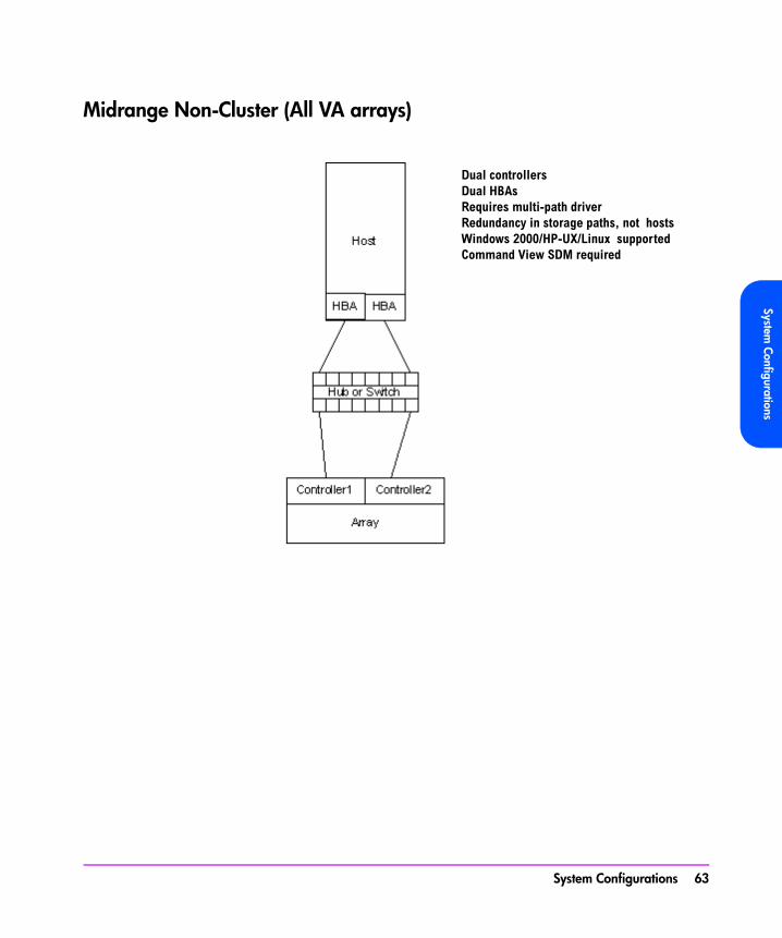
Midrange Non-Cluster (All VA arrays)
Dual controllers Dual HBAsRequires multi-path driverRedundancy in storage paths, not hosts Windows 2000/HP-UX/Linux supportedCommand View SDM required
System Configurations 63
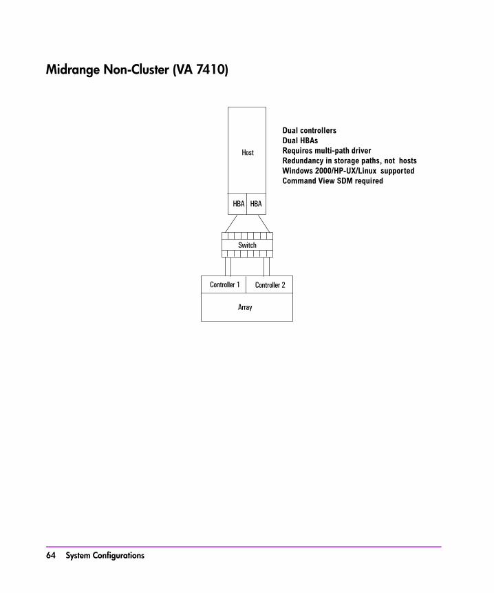
Midrange Non-Cluster (VA 7410)
Array
Controller 1 Controller 2
Host
HBA HBA
Switch
Dual controllers Dual HBAsRequires multi-path driverRedundancy in storage paths, not hosts Windows 2000/HP-UX/Linux supportedCommand View SDM required
64 System Configurations
System Configurations
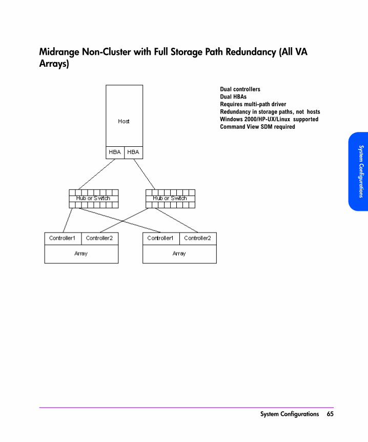
Midrange Non-Cluster with Full Storage Path Redundancy (All VA Arrays)
Dual controllers Dual HBAsRequires multi-path driverRedundancy in storage paths, not hosts Windows 2000/HP-UX/Linux supportedCommand View SDM required
System Configurations 65
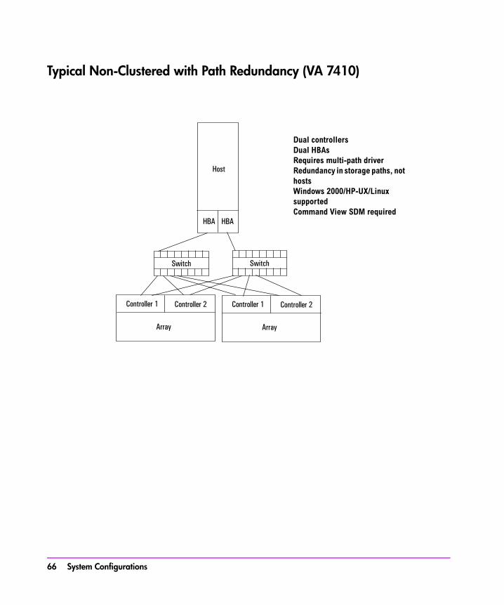
Typical Non-Clustered with Path Redundancy (VA 7410)
Array
Controller 1 Controller 2
Host
HBA HBA
Switch Switch
Array
Controller 1 Controller 2
Dual controllers Dual HBAsRequires multi-path driverRedundancy in storage paths, not hosts Windows 2000/HP-UX/Linux supportedCommand View SDM required
66 System Configurations

System Configurations
Typical Clustered Configuration (All VA models)
Dual controller Single HBA per hostRedundancy in storage paths, not hosts Windows 2000/HP-UX/Linux supportedCommand View SDM required
System Configurations 67
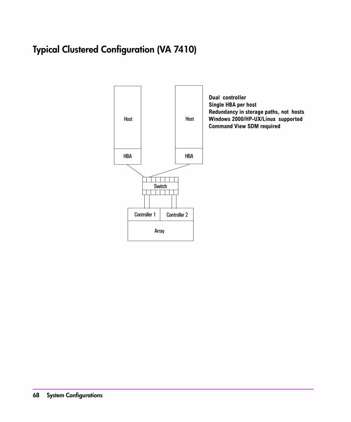
Typical Clustered Configuration (VA 7410)
Array
Controller 1 Controller 2
Host
HBA
Switch
Host
HBA
Dual controller Single HBA per hostRedundancy in storage paths, not hosts Windows 2000/HP-UX/Linux supportedCommand View SDM required
68 System Configurations
System Configurations
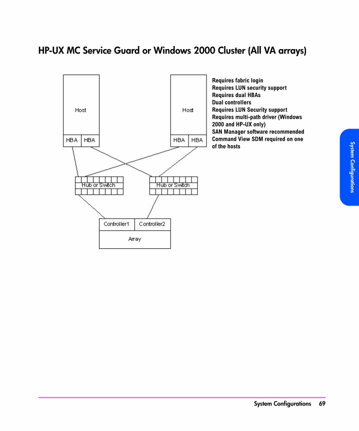
HP-UX MC Service Guard or Windows 2000 Cluster (All VA arrays)
Requires fabric loginRequires LUN security supportRequires dual HBAsDual controllersRequires LUN Security supportRequires multi-path driver (Windows 2000 and HP-UX only)SAN Manager software recommendedCommand View SDM required on one of the hosts
System Configurations 69

Highly Redundant Cluster (VA 7410)
Array
Controller 1 Controller 2
Host
HBA HBA
Switch Switch
Host
HBA HBA
Requires fabric loginRequires LUN security supportRequires dual HBAsDual controllersRequires LUN Security supportRequires multi-path driver (Windows 2000 and HP-UX only)SAN Manager software recommendedCommand View SDM required on one of the hosts
70 System Configurations
System Configurations
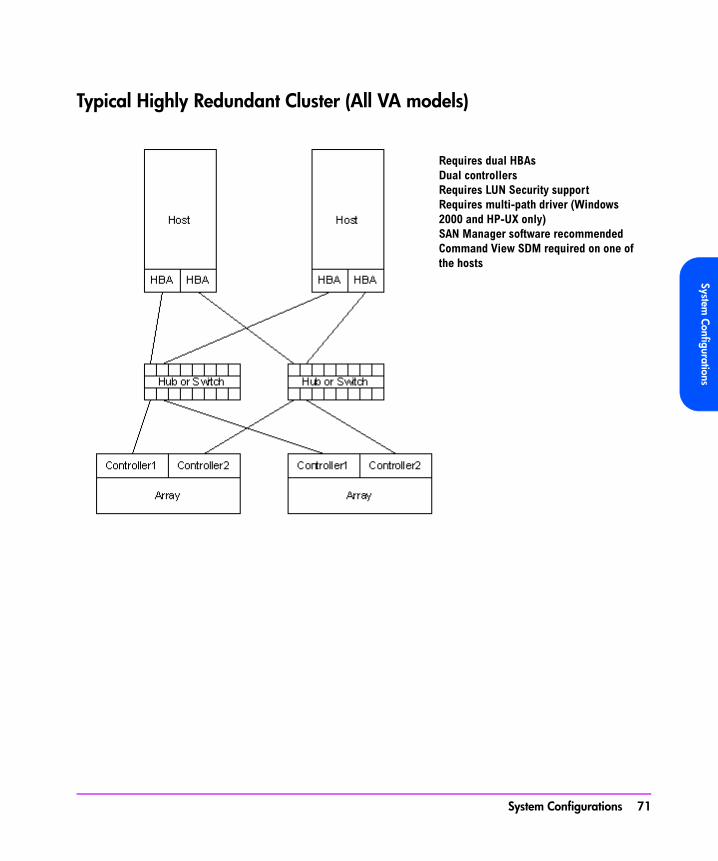
Typical Highly Redundant Cluster (All VA models)
Requires dual HBAsDual controllersRequires LUN Security supportRequires multi-path driver (Windows 2000 and HP-UX only)SAN Manager software recommendedCommand View SDM required on one of the hosts
System Configurations 71
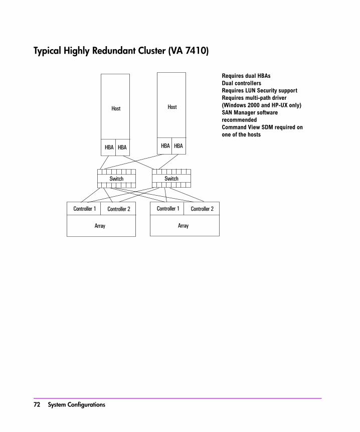
Typical Highly Redundant Cluster (VA 7410)
Array
Controller 1 Controller 2
Host
HBA HBA
Switch Switch
Host
HBA HBA
Array
Controller 1 Controller 2
Requires dual HBAsDual controllersRequires LUN Security supportRequires multi-path driver (Windows 2000 and HP-UX only)SAN Manager software recommendedCommand View SDM required on one of the hosts
72 System Configurations

3
TroubleshootingThis chapter describes how to troubleshoot the array if a failure occurs. A failure may be indicated by any of the following:
■ array status LEDs
■ array management software
■ host applications
This chapter will only discuss the first two indicators. Refer to your host application documentation for host application failure indications.
Caution To avoid data loss or downtime, it is essential that during troubleshooting the array remain properly configured and the correct repair procedures are followed. If you are unfamiliar with the error condition the array is experiencing, do not remove or reset controllers, disconnect controller batteries, or remove power from the array before contacting your HP storage specialist for assistance.
Troubleshooting 73
Troubleshooting StepsFollow these basic steps for troubleshooting the array:
1 Check the state of the array and the status of the field replaceable units (FRUs) in the array. See "Array State & Status" on page 76.
2 Check the array controller logs. See "Checking Array Controller Logs" on page 87.
3 Replace any faulty FRU or repair the array.
4 Verify the array is operational and that no amber fault LEDs, error messages, or Warning states are displayed.
74 Troubleshooting
Troubleshooting
Redundant FRUsThe following FRUs are redundant. If they fail, the array is still available to the host for I/O activity:
■ 1 disk drive (per enclosure)
■ 1 power module (per enclosure)
■ 1 array controller card (controller enclosure)
■ 1 link controller card (disk enclosure)
Troubleshooting 75

Array State & StatusThe state of the array is indicated by CommandView SDM software with the following state parameters (state messages in parenthesis):
■ Array Controller (Controller Mismatch, Mismatched Code, No Code, No Map)
■ Disk Drives (Disk Format Mismatch, No Quorum, Not Enough Drives)
■ Array Readiness (Ready, Shutdown, Shutdown Warning, Shutting Down, Starting Up)
■ Array Warnings (Active Spare Unavailable, Battery Failure, Code Mismatch, Controller Mismatch, Controller Problem, Data Unavailable, Drive Configuration Problem, FRU Monitor Problem, Insufficient Map Disks, Link Down, No Map Disks, NVRAM Battery Depletion, Over Temperature Condition, Physical Drive Problem, Power Supply Failed, Rebuild Failed, State Changing)
The status of the array refers to a normal or fault condition for each FRU within the array. Any of the following tools can be used to determine the state and status of the array:
— LED hardware status indicators— CommandView SDM software— Virtual Front Panel (VFP)
Note If the host can communicate with the array, CommandView SDM should be used to discover the state and status of the array.
If the host cannot communicate with the array, the VFP will have to be used to determine the state of the array and to begin troubleshooting.
Link Down Warning State
Note A link consists of two unidirectional fibers, transmitting in opposite directions, and their associated transmitters and receivers which communicate between nodes in a Fibre Channel-Arbitrated Loop.
76 Troubleshooting
Troubleshooting
A Link Down warning state can be reported by the CVGUI if either of the following two failures occur:
■ If a host Fibre Channel loop fails due to the failure of a host HBA, a faulty or disconnected fiber cable, a faulty GBIC (VA 7100 only), or the failure of a data flow component on an array controller.
■ If an array Fibre Channel loop fails due to a port failure on a disk drive, faulty loop circuitry on the midplane, or the failure of a data flow component on an array controller. If a port failure occurs, a port bypass circuit will bypass that part of the loop and the first array controller will re-route the data through the second array controller, via the internal N-way bus, to the other Fibre Channel loop.
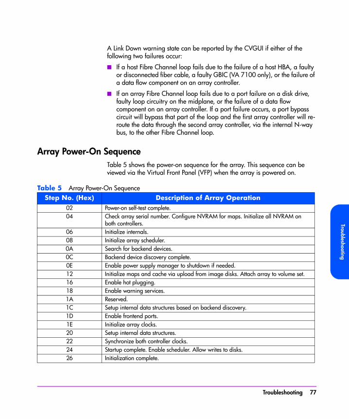
Array Power-On SequenceTable 5 shows the power-on sequence for the array. This sequence can be viewed via the Virtual Front Panel (VFP) when the array is powered on.
Table 5 Array Power-On SequenceStep No. (Hex) Description of Array Operation
02 Power-on self-test complete.04 Check array serial number. Configure NVRAM for maps. Initialize all NVRAM on
both controllers.06 Initialize internals.08 Initialize array scheduler.0A Search for backend devices.0C Backend device discovery complete.0E Enable power supply manager to shutdown if needed.12 Initialize maps and cache via upload from image disks. Attach array to volume set.16 Enable hot plugging.18 Enable warning services.1A Reserved.1C Setup internal data structures based on backend discovery.1D Enable frontend ports.1E Initialize array clocks.20 Setup internal data structures.22 Synchronize both controller clocks.24 Startup complete. Enable scheduler. Allow writes to disks.26 Initialization complete.
Troubleshooting 77
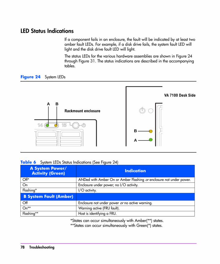
LED Status IndicationsIf a component fails in an enclosure, the fault will be indicated by at least two amber fault LEDs. For example, if a disk drive fails, the system fault LED will light and the disk drive fault LED will light.
The status LEDs for the various hardware assemblies are shown in Figure 24 through Figure 31. The status indications are described in the accompanying tables.
Figure 24 System LEDs
Table 6 System LEDs Status Indications (See Figure 24)
*States can occur simultaneously with Amber(**) states.**States can occur simultaneously with Green(*) states.
A System Power/Activity (Green) Indication
Off* ANDed with Amber On or Amber Flashing or enclosure not under power.On Enclosure under power; no I/O activity.Flashing* I/O activity.
B System Fault (Amber)Off Enclosure not under power or no active warning.On** Warning active (FRU fault).Flashing** Host is identifying a FRU.
A B
B
A
Rackmount enclosure
VA 7100 Desk Side
78 Troubleshooting

Troubleshooting
Figure 25 Disk Drive LEDs (Left: VA 71/7400 A/AZ; Right: VA 7100 D)
Table 7 Disk Drive LEDs Status Indications (See Figure 25)
*Controlled by the disk drive.
**Controlled by the array controller.
Note
— In a controller enclosure, the amber disk fault LED will flash during an Auto Format process or when downing a disk drive. On a disk enclosure, the amber system fault LED will also flash.
ADisk
Activity(Green*)
BDisk Fault(Amber**)
Indication
Off Off Disk not under power.On Off Disk drive under power and operating normally.Off On Disk drive fault.On On Disk drive fault.
Flashing Off Disk drive self-test in progress or I/O activity.On/Off Flashing Host is identifying disk drive.
AB
A B
Troubleshooting 79

Figure 26 VA 7100 Array Controller LEDs
Table 8 HOST FC LEDs Status Indications (See Figure 26)
Figure 27 VA 7400 Array Controller LEDs
Table 9 DISK FC & HOST FC LED Status Indications (See Figure 27)
HOST FCGBIC Active
(Green)
HOST FCGBIC Fault(Amber)
Indication
Off Off GBIC not under power or link down or GBIC not installed.On Off GBIC installed and operating normally.Off On GBIC fault; GBIC not able to generate Transmit signal.Off Flashing GBIC fault; GBIC has lost Receive signal.
DISK FC Indication
Off Unit not under power or disk enclosure (backend) FC link down.On Valid Fibre Channel link to disk enclosure.
HOST FC
Off Unit not under power or host (frontend) FC link down.On Valid Fibre Channel link to host.
80 Troubleshooting
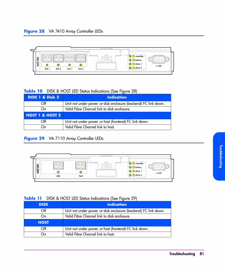
Troubleshooting
Figure 28 VA 7410 Array Controller LEDs
Table 10 DISK & HOST LED Status Indications (See Figure 28)
Figure 29 VA 7110 Array Controller LEDs
Table 11 DISK & HOST LED Status Indications (See Figure 29)
DISK 1 & Disk 2 Indication
Off Unit not under power or disk enclosure (backend) FC link down.On Valid Fibre Channel link to disk enclosure.
HOST 1 & HOST 2
Off Unit not under power or host (frontend) FC link down.On Valid Fibre Channel link to host.
DISK Indication
Off Unit not under power or disk enclosure (backend) FC link down.On Valid Fibre Channel link to disk enclosure.
HOST
Off Unit not under power or host (frontend) FC link down.On Valid Fibre Channel link to host.
hostdisk
A62
18A
Troubleshooting 81

Table 12 CONTROLLER LEDs Status Indications (See Figure 26, 27, 28, or 29)
*Can be on, off, or flashing
Table 13 BATTERY LEDs Status Indications (See Figure 26, 27, or 28)
Table 14 DIMM 1 & DIMM 2 LEDs Status Indications (See Figure 26, 27, or 28)
CONTROLLERActive
(Green)
CONTROLLERFault
(Amber)Indication
Off Off Array controller not under power.On Off Array controller under power and operating normally.* On Array controller fault.
Flashing * I/O activity.* Flashing Host identifying array controller.
BATTERYActive
(Green)
BATTERYFault
(Amber)Indication
Off Off New battery or battery totally depleted.On Off Battery under power and operating normally.On On Battery failed or battery has reached end of usable life.
Flashing50% Duty Cycle
Off Battery self-test in progress.
Flashing5% Duty Cycle
Off Battery is powering NVSDRAM contents.
On Flashing Indicates that the controller is updating the battery firmware. Under normal circumstances this condition should only occur for a few seconds. If this condition persists, it indicates a problem with the controller and/or battery.
DIMM 1/DIMM 2Active
(Green)
DIMM 1/DIMM 2
Fault(Amber)
Indication
Off Off DIMM not under power or DIMM not installed.On Off DIMM under power and operating normally.Off On DIMM fault.
82 Troubleshooting
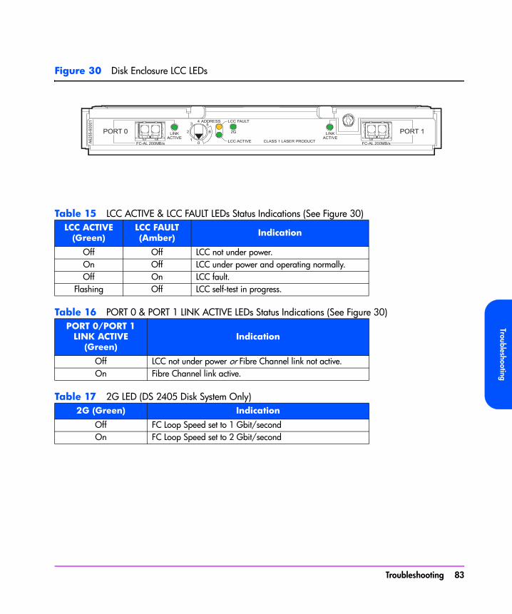
Troubleshooting
Figure 30 Disk Enclosure LCC LEDs
Table 15 LCC ACTIVE & LCC FAULT LEDs Status Indications (See Figure 30)
Table 16 PORT 0 & PORT 1 LINK ACTIVE LEDs Status Indications (See Figure 30)
Table 17 2G LED (DS 2405 Disk System Only)
LCC ACTIVE (Green)
LCC FAULT(Amber) Indication
Off Off LCC not under power.On Off LCC under power and operating normally.Off On LCC fault.
Flashing Off LCC self-test in progress.
PORT 0/PORT 1LINK ACTIVE
(Green)Indication
Off LCC not under power or Fibre Channel link not active.On Fibre Channel link active.
2G (Green) Indication
Off FC Loop Speed set to 1 Gbit/secondOn FC Loop Speed set to 2 Gbit/second
Troubleshooting 83
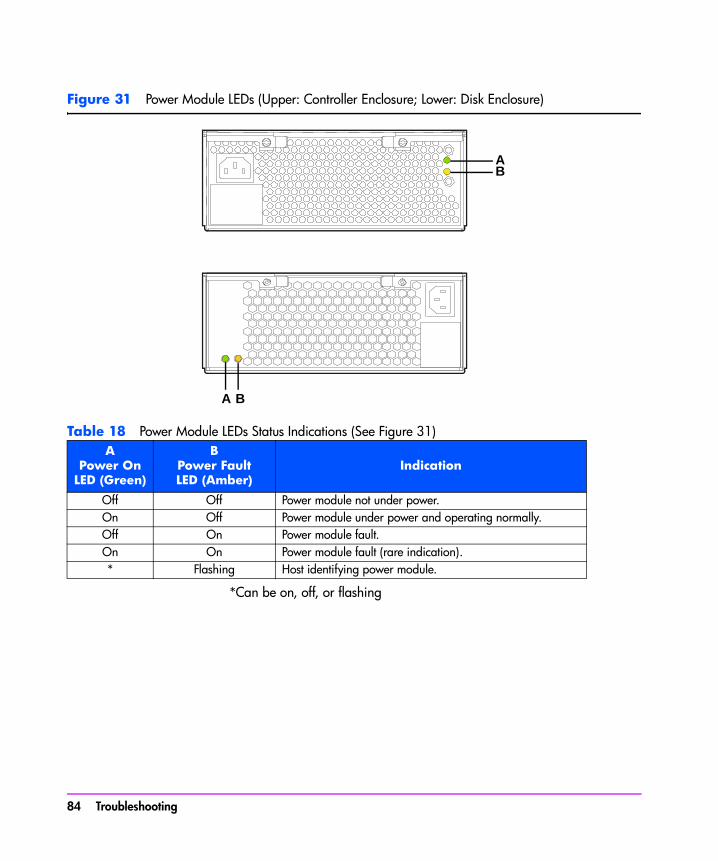
Figure 31 Power Module LEDs (Upper: Controller Enclosure; Lower: Disk Enclosure)
Table 18 Power Module LEDs Status Indications (See Figure 31)
*Can be on, off, or flashing
APower On
LED (Green)
BPower FaultLED (Amber)
Indication
Off Off Power module not under power.On Off Power module under power and operating normally.Off On Power module fault.On On Power module fault (rare indication).* Flashing Host identifying power module.
AB
A B
84 Troubleshooting

Troubleshooting
Tools for Checking Array State & Status
CommandView SDM GUI1 The array state is displayed with an icon in the upper left-hand corner
(banner area) of the screen.
2 Click on the “Status” tab. Click on “Array Status” and view the “Overall Array State” and “Warning States”. Click the Help button for a description of the problem and solution for “Warning States”. Click on “Component Status” then click on a component in the “Selected Enclosure” box on the left-hand side to display the status of any array component. Click the Help button for a description of the status for each component.
3 Click on the “Diagnostics” tab. Click on “Array” to display the same information as “Array Status” under the “Status” tab. Click on “Disk” then click on “Condition” to display the status of the disks in the array. Click on “State” to see if the disks are currently included or not included.
CommandView SDM CLUI1 Use the “armdsp -a” command to display the Array State messages and
detailed information about the FRUs in the array.
2 Use the “armdsp -f” command to quickly display any FRU Status messages.
CommandView SDM CVUI1 Select “Storage->HpArrayMain->Properties->Config&Status” to display the
Array State messages and detailed information about the FRUs in the array.
2 Select “Storage->HpArrayMain->Properties->Components” to quickly display any FRU Status messages.
VFP1 Use the “vfpdsp” command to display the Array State messages and
detailed information about the FRUs in the array.
2 Use the “vfpdsp -f” command to quickly display any FRU Status messages.
Troubleshooting 85
Array Controller Logs
Types of Array Controller LogsThere are two types of array controller logs:
■ Controller logs. Controller logs contain events relating to the operation of all FRUs in the array, obtained from the controller during the operation of the array. The CommandView SDM logging routine polls the array every 15 minutes to retrieve and store the log entries in special controller log files. Each log entry has a decimal event number and an event name. A list of the “Controller Log Event Code Descriptions” is available at:
http://www.hp.com/support/va7100http://www.hp.com/support/va7400http://www.hp.com/support/va7410http://www.hp.com/support/va7110
■ Usage logs. Entries for the usage log are created using the output of the armdsp -a command. The CommandView SDM logging routine runs the command and stores its output as entries in the usage log file. This occurs every 24 hours by default, but can be changed to a setting from 1 to 100 hours.
Location of Array Controller LogsArray controller logs are stored in three locations:
■ NVSDRAM. 256 kilobytes of NVSDRAM memory is reserved to hold one thousand log entries.
■ Image Disks. The logs in NVSDRAM are mirrored and backed up by the image disks.
■ Host OS directory. Polls the controller every 10 minutes and updates the following host directory, located on the host internal disk:<command view home dir>/sanmgr/cmdview/server/logs
86 Troubleshooting
Troubleshooting
Checking Array Controller LogsCheck the array controller logs using one of the following methods:
■ CommandView SDM Command Line User Interface (CLUI). Refer to the armlog command in the HP CommandView SDM Installation & User Guide.
■ CommandView SDM CommandView User Interface (CVUI). Refer to the following menu in the HP CommandView SDM Installation & User Guide:“Storage->HpArrayMain->Diagnostics->ArrayLogs”
Troubleshooting 87
EMS Hardware Monitors (HP-UX Only)With Event Monitoring Service (EMS) you can be alerted to problems as they occur, allowing you to respond quickly to correct a problem before it impacts the operation of the array. All operational aspects of the array are monitored. EMS gives you the flexibility to deliver event notification using a variety of methods.
EMS is enabled automatically during installation of the CommandView SDM software, ensuring immediate detection and reporting of array events.
The EMS monitor used for the HP StorageWorks Virtual Array products is the Remote Monitor. Information on this EMS monitor can be found at the Systems, Hardware, Diagnostics, and Monitoring section of HP’s Online Documentation Web site:
http://www.docs.hp.com/hpux/diag/
Here you can find the Remote Monitor data sheet and a description of the events generated by the array.
Note On HP-UX systems, SAM may incorrectly identify the VA7110 as a VA7405.
EMS Event Severity LevelsEach event detected and reported by the EMS monitor is assigned a severity level, which indicates the impact the event may have on the operation of the array. The following severity levels are used for all events:
■ Critical - An event that causes host system downtime, or other loss of service. Host system operation will be affected if the disk system continues to be used without correction of the problem. Immediate action is required.
■ Serious - An event that may cause, host system downtime, or other loss of service if left uncorrected. Host system and hardware operation may be adversely affected. The problem needs repair as soon as possible.
■ Major Warning - An event that could escalate to a serious condition if not corrected. Host system operation should not be affected and normal use of the disk system can continue. Repair is needed but at a convenient time.
■ Minor Warning - An event that will not likely escalate to a severe condition if left uncorrected. Host system operation will not be interrupted and normal
88 Troubleshooting

Troubleshooting
use of the disk system can continue. The problem can be repaired at a convenient time.
■ Information - An event that is expected as part of the normal operation of the hardware. No action is required.
EMS Event MessageAn EMS event message typically includes the following information:
■ Message Data - Date and time the message was sent, the source and destination of the message, and the severity level.
■ Event Data - Date and time of the event, the host, event ID, name of the monitor, event number, event class, severity level, hardware path, and associated OS error log entry ID.
■ Error Description - Information indicating the component that experienced the event and the nature of the event.
■ Probable Cause/Recommended Action - The cause of the event and suggested steps toward a solution. This information should be the first step in troubleshooting the array.
A typical event would appear as:Event 2026, Severity: Serious Event Summary: Enclosure controller failed. Event Description: The enclosure controller has failed. Probable Cause/ Recommended Action: Replace the FRU(Field Replaceable Unit).
Troubleshooting 89

90 Troubleshooting

4
Servicing & UpgradingThis chapter includes removal and replacement procedures for the field replaceable units (FRUs) listed in Table 19. It also includes array upgrade procedures.
Servicing & Upgrading 91
Field Replaceable Units (FRUs)
Identifying FRUsThere are two types of field replaceable units:
■ “HP Service Personnel Only”. These units that can be serviced only by HP service personnel, or by qualified service representatives. They are designated as “HP” in Table 19 and Table 20.
■ “Customer Replaceable Units”. These units can be serviced by a customer, or by HP service personnel or qualified service representatives. (A “customer” is defined as any person responsible for the administration, operation, or management of the array.) They are designated as “CRU” in Table 19 and Table 20.
Note The FRU type designations also apply to upgrade kits. For example, only HP service personnel should install an upgrade array controller, but a customer may install an upgrade disk drive to increase capacity.
Refer to the following figures and tables to identify FRUs in the controller enclosure and the disk enclosure:
■ Figure 32 shows the locations of the controller enclosure FRUs and Table 19 lists their part numbers.
■ Figure 33 shows the locations of the disk enclosure FRUs and Table 20 lists their part numbers.
Note Both DS 2400 Disk Systems and DS 2405 Disk Systems are used as disk enclosures in the VA 7400/7410. Where necessary, the differences in these products are identified.
An easy way of determining which type of disk system is installed is to use the armdsp -c command. The Controller Type field indicates the type of disk enclosure, DS 2400 or DS 2405.
92 Servicing & Upgrading

Servicing & U
pgrading
Figure 32 Controller Enclosure FRUs
Table 19 Controller Enclosure Field Replaceable Units
Fig. 23Item Part No. FRU Description
Qty PerEncl.
Exch./Repl.Part
FRUType
1 A6191-69001 Disk Drive, 18GB, 15k rpm, 512 bytes/sector 4-151
10-152E CRU
1 A6192-69001 Disk Drive, 36GB, 10k rpm, 512 bytes/sector 4-151
10-152E CRU
1 A6194-69001 Disk Drive, 73GB, 10k rpm, 512 bytes/sector 4-151
10-152E CRU
1 A7288-69001 Disk Drive, 73GB, 15k rpm, 512 bytes/sector (Supported on VA 7110 and VA 7410 only)
4-151
10-152E CRU
1
2
3
4 56
7
8
Servicing & Upgrading 93
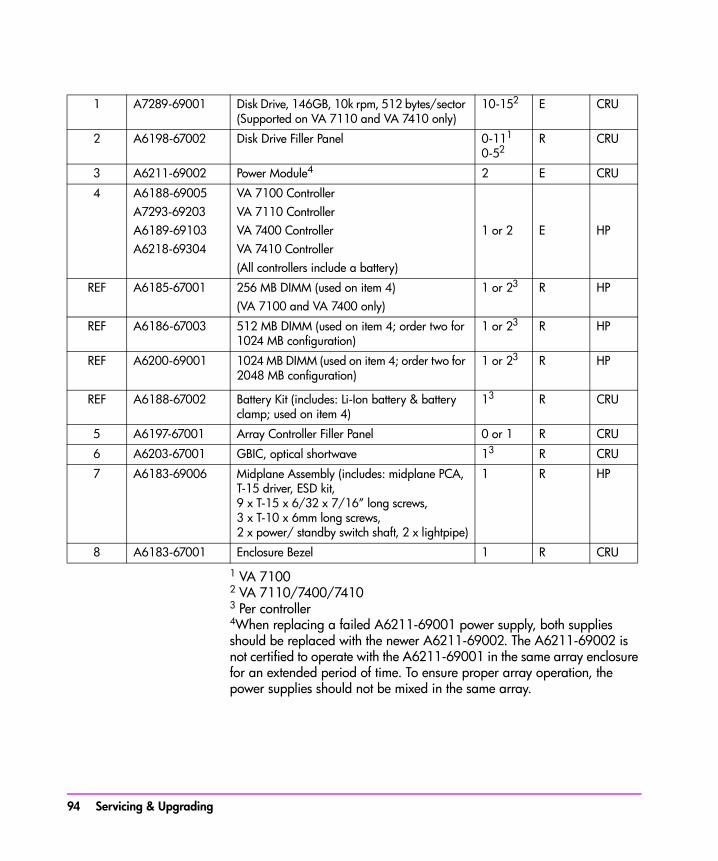
1 VA 71002 VA 7110/7400/74103 Per controller4When replacing a failed A6211-69001 power supply, both supplies should be replaced with the newer A6211-69002. The A6211-69002 is not certified to operate with the A6211-69001 in the same array enclosure for an extended period of time. To ensure proper array operation, the power supplies should not be mixed in the same array.
1 A7289-69001 Disk Drive, 146GB, 10k rpm, 512 bytes/sector (Supported on VA 7110 and VA 7410 only)
10-152 E CRU
2 A6198-67002 Disk Drive Filler Panel 0-111
0-52R CRU
3 A6211-69002 Power Module4 2 E CRU
4 A6188-69005A7293-69203A6189-69103A6218-69304
VA 7100 ControllerVA 7110 ControllerVA 7400 ControllerVA 7410 Controller(All controllers include a battery)
1 or 2 E HP
REF A6185-67001 256 MB DIMM (used on item 4)(VA 7100 and VA 7400 only)
1 or 23 R HP
REF A6186-67003 512 MB DIMM (used on item 4; order two for 1024 MB configuration)
1 or 23 R HP
REF A6200-69001 1024 MB DIMM (used on item 4; order two for 2048 MB configuration)
1 or 23 R HP
REF A6188-67002 Battery Kit (includes: Li-Ion battery & battery clamp; used on item 4)
13 R CRU
5 A6197-67001 Array Controller Filler Panel 0 or 1 R CRU
6 A6203-67001 GBIC, optical shortwave 13 R CRU
7 A6183-69006 Midplane Assembly (includes: midplane PCA, T-15 driver, ESD kit, 9 x T-15 x 6/32 x 7/16” long screws, 3 x T-10 x 6mm long screws, 2 x power/ standby switch shaft, 2 x lightpipe)
1 R HP
8 A6183-67001 Enclosure Bezel 1 R CRU
94 Servicing & Upgrading
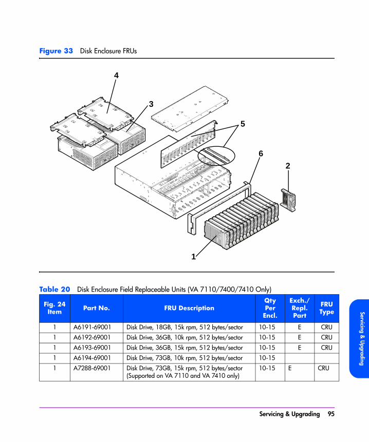
Servicing & U
pgrading
Figure 33 Disk Enclosure FRUs
Table 20 Disk Enclosure Field Replaceable Units (VA 7110/7400/7410 Only)
Fig. 24Item Part No. FRU Description
Qty PerEncl.
Exch./Repl.Part
FRUType
1 A6191-69001 Disk Drive, 18GB, 15k rpm, 512 bytes/sector 10-15 E CRU
1 A6192-69001 Disk Drive, 36GB, 10k rpm, 512 bytes/sector 10-15 E CRU
1 A6193-69001 Disk Drive, 36GB, 15k rpm, 512 bytes/sector 10-15 E CRU
1 A6194-69001 Disk Drive, 73GB, 10k rpm, 512 bytes/sector 10-15
1 A7288-69001 Disk Drive, 73GB, 15k rpm, 512 bytes/sector (Supported on VA 7110 and VA 7410 only)
10-15 E CRU
1
2
3
4
5
6
Servicing & Upgrading 95
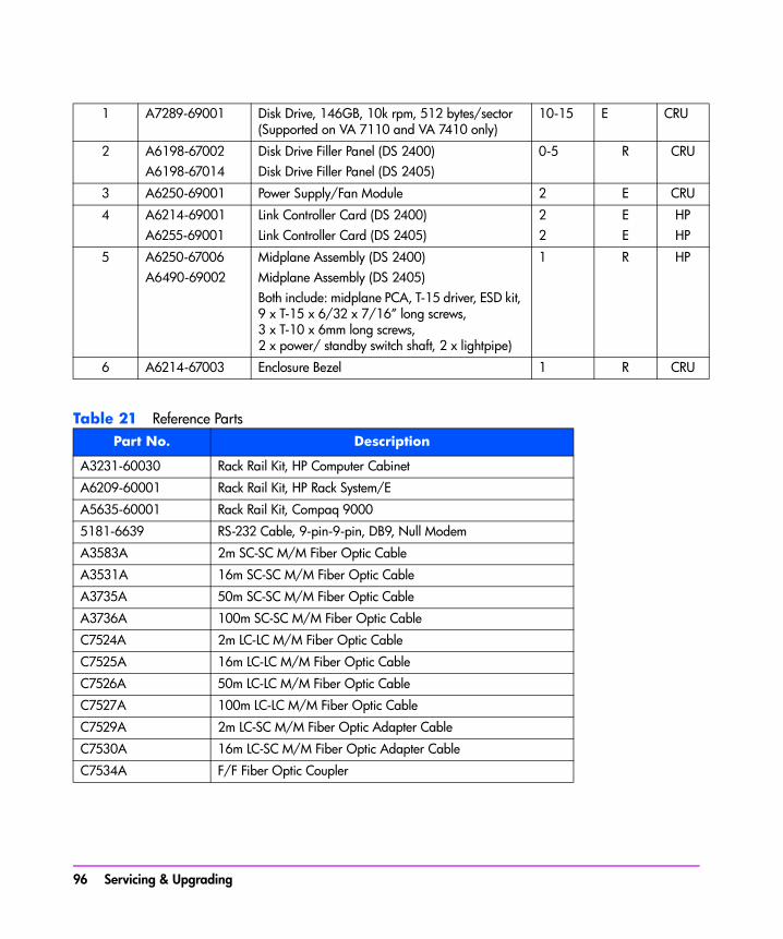
Table 21 Reference Parts
1 A7289-69001 Disk Drive, 146GB, 10k rpm, 512 bytes/sector (Supported on VA 7110 and VA 7410 only)
10-15 E CRU
2 A6198-67002A6198-67014
Disk Drive Filler Panel (DS 2400)Disk Drive Filler Panel (DS 2405)
0-5 R CRU
3 A6250-69001 Power Supply/Fan Module 2 E CRU
4 A6214-69001A6255-69001
Link Controller Card (DS 2400)Link Controller Card (DS 2405)
22
EE
HPHP
5 A6250-67006A6490-69002
Midplane Assembly (DS 2400)Midplane Assembly (DS 2405)Both include: midplane PCA, T-15 driver, ESD kit, 9 x T-15 x 6/32 x 7/16” long screws, 3 x T-10 x 6mm long screws, 2 x power/ standby switch shaft, 2 x lightpipe)
1 R HP
6 A6214-67003 Enclosure Bezel 1 R CRU
Part No. Description
A3231-60030 Rack Rail Kit, HP Computer Cabinet
A6209-60001 Rack Rail Kit, HP Rack System/E
A5635-60001 Rack Rail Kit, Compaq 9000
5181-6639 RS-232 Cable, 9-pin-9-pin, DB9, Null Modem
A3583A 2m SC-SC M/M Fiber Optic Cable
A3531A 16m SC-SC M/M Fiber Optic Cable
A3735A 50m SC-SC M/M Fiber Optic Cable
A3736A 100m SC-SC M/M Fiber Optic Cable
C7524A 2m LC-LC M/M Fiber Optic Cable
C7525A 16m LC-LC M/M Fiber Optic Cable
C7526A 50m LC-LC M/M Fiber Optic Cable
C7527A 100m LC-LC M/M Fiber Optic Cable
C7529A 2m LC-SC M/M Fiber Optic Adapter Cable
C7530A 16m LC-SC M/M Fiber Optic Adapter Cable
C7534A F/F Fiber Optic Coupler
96 Servicing & Upgrading
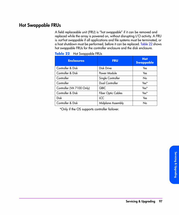
Servicing & U
pgrading
Hot Swappable FRUsA field replaceable unit (FRU) is “hot swappable” if it can be removed and replaced while the array is powered on, without disrupting I/O activity. A FRU is not hot swappable if all applications and file systems must be terminated, or a host shutdown must be performed, before it can be replaced. Table 22 shows hot swappable FRUs for the controller enclosure and the disk enclosure.
Table 22 Hot Swappable FRUs
*Only if the OS supports controller failover.
Enclosures FRU Hot Swappable
Controller & Disk Disk Drive Yes
Controller & Disk Power Module Yes
Controller Single Controller No
Controller Dual Controller Yes*
Controller (VA 7100 Only) GBIC Yes*
Controller & Disk Fiber Optic Cables Yes*
Disk LCC Yes
Controller & Disk Midplane Assembly No
Servicing & Upgrading 97
Controller Enclosure Removal & Installation Procedures
Disk DrivesThe following procedure is used for disks in both the controller enclosure and the disk enclosure.
Removing a Disk DriveCaution Do not operate the array for more than 5 minutes with a disk
drive or filler panel removed. Either a disk drive or filler panel must be installed in the slot to maintain proper airflow.
1 Push down the release tab (Figure 34, 1) and pull up the cam lever (2).
Caution Wait 15 seconds for the disk drive to stop spinning before fully removing it from the array enclosure. Removing a disk drive while it is spinning may cause damage to the disk spindle bearings.
2 Pull the disk drive (3) out of the slot.
Installing a Disk Drive
1 Push down the release tab (Figure 34, 1) and pull up the cam lever (2).
2 Push the disk drive (3) firmly into the slot.
3 Push down the cam lever until it clicks into place to secure the disk drive.
Note An exchange disk drive comes formatted with 512-byte sectors. After installation, the controller starts the Auto Format process to automatically format the disk drive with 520-byte sectors. Table 23 indicates the times required for formatting the different capacity disks. During this time, the green disk activity LED will be flashing.
98 Servicing & Upgrading

Servicing & U
pgrading
Table 23 Raw Format Times (Verify Off)
Caution To prevent corruption of the disk format, do not remove a newly installed disk drive or power-off the array during the Auto Format process. If a disk is removed during an Auto Format, the array will automatically re-start the Auto Format process from the beginning.
Figure 34 Removing & Installing a Disk Drive
Disk Capacity
Format Time (Minutes)
18 GB 15K 8
36 GB 10K 20
73 GB 10K 28
73 GB 15K 20
146 GB 10K 46
12
3
Servicing & Upgrading 99

Disk Drive Filler PanelsThere are two types of disk filler panels: the larger type B shown in Figure 35 and the smaller type A shown in Figure 36. The type B filler panel can be identified by the blue release tab and the locking cam lever.
Caution Do not operate the array for more than 5 minutes with a disk drive or filler panel removed. Either a disk drive or filler panel must be installed in the slot to maintain proper airflow.
Make sure you install the correct type of filler panel. If the wrong panel is used, it may become stuck in the enclosure. Before installing a filler panel, make sure it is the same type as the other filler panels in the enclosure.
Removing a Type B Disk Drive Filler Panel
1 Push down the release tab (Figure 35, 1) and pull up the cam lever (2).
2 Pull the disk drive filler panel (3) out of the slot.
Installing a Type B Disk Drive Filler Panel
1 Push down the release tab (Figure 35, 1) and pull up the cam lever (2).
2 Push the filler panel (3) firmly into the slot.
3 Push down the cam lever until it clicks into place.
Removing a Type A Disk Drive Filler Panel■ Pull the disk drive filler panel out of the slot (Figure 36).
Installing a Type A Disk Drive Filler Panel■ Push the filler panel firmly into the slot.
100 Servicing & Upgrading
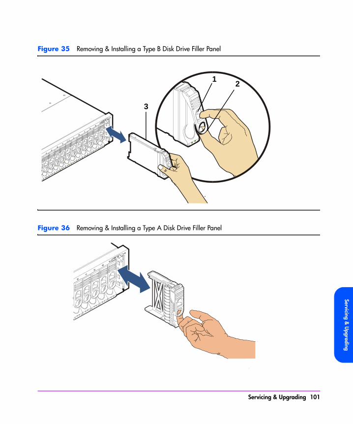
Servicing & U
pgrading
Figure 35 Removing & Installing a Type B Disk Drive Filler Panel
Figure 36 Removing & Installing a Type A Disk Drive Filler Panel
3
12
Servicing & Upgrading 101

Power Modules
Removing a Power ModuleCaution Do not operate the array for more than 2 minutes with a power
module removed, or the array may automatically initiate a shutdown. At least one power module must be installed and operational at all times to maintain adequate power and airflow.
Always disconnect the power cord from the power module before removing it from the enclosure. Failure to disconnect the power cord may result in power spikes that may potentially cause disk drive problems such as reset or spin down.
1 Disconnect the power cord.
2 Loosen the cam lever screws (Figure 37, 1) with a T-10 driver or flat-blade screwdriver.
3 Pull out both cam levers (2) at the same time.
4 Pull the power module (3) out of the slot.
Installing a Power Module
Note Two models of power supplies are available for the array: the older A6211-69001 and the newer A6211-69002. The A6211-69002 is not certified to operate with the A6211-69001 in the same array enclosure for an extended period of time. To ensure proper array operation, the power supplies should not be mixed in the same array.
1 Pull out both cam levers (Figure 37, 2) at the same time.
2 Push the power module (3) firmly into the slot.
3 Push in both cam levers at the same time.
4 Tighten the cam lever screws (1) with a T-10 driver or flat-blade screwdriver.
5 Re-connect the power cord.
102 Servicing & Upgrading
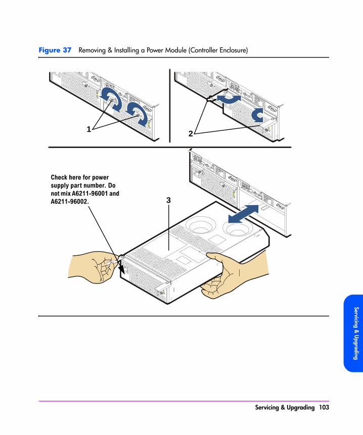
Servicing & U
pgrading
Figure 37 Removing & Installing a Power Module (Controller Enclosure)
1 2
3
Check here for power supply part number. Do not mix A6211-96001 and A6211-96002.
Servicing & Upgrading 103
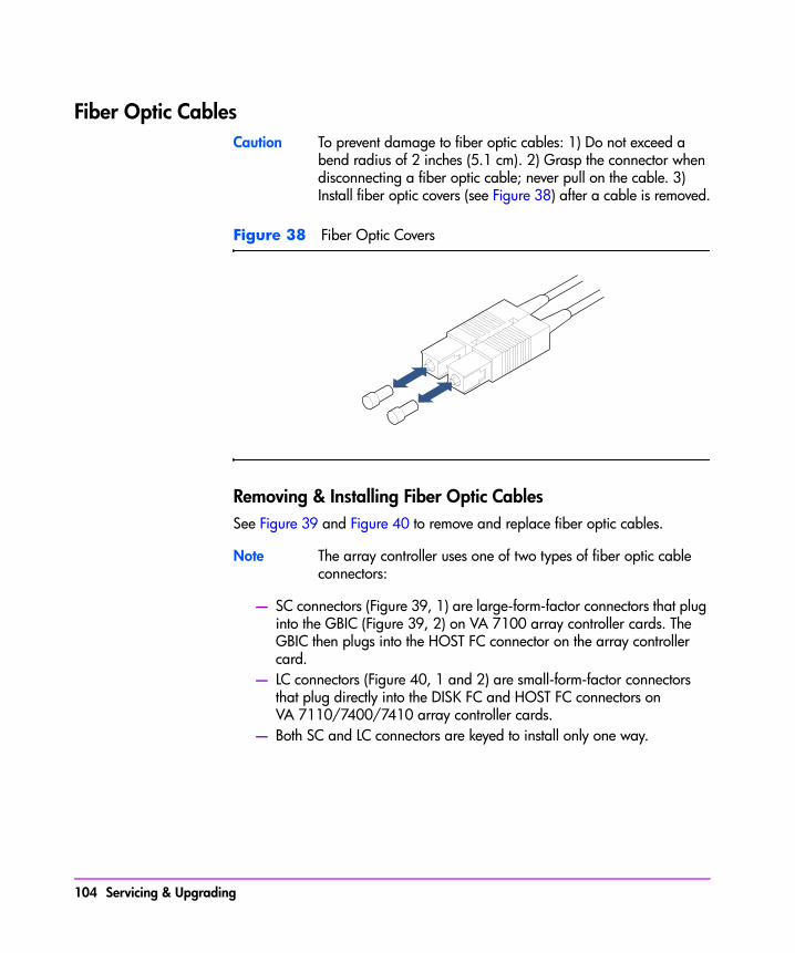
Fiber Optic CablesCaution To prevent damage to fiber optic cables: 1) Do not exceed a
bend radius of 2 inches (5.1 cm). 2) Grasp the connector when disconnecting a fiber optic cable; never pull on the cable. 3) Install fiber optic covers (see Figure 38) after a cable is removed.
Figure 38 Fiber Optic Covers
Removing & Installing Fiber Optic CablesSee Figure 39 and Figure 40 to remove and replace fiber optic cables.
Note The array controller uses one of two types of fiber optic cable connectors:
— SC connectors (Figure 39, 1) are large-form-factor connectors that plug into the GBIC (Figure 39, 2) on VA 7100 array controller cards. The GBIC then plugs into the HOST FC connector on the array controller card.
— LC connectors (Figure 40, 1 and 2) are small-form-factor connectors that plug directly into the DISK FC and HOST FC connectors on VA 7110/7400/7410 array controller cards.
— Both SC and LC connectors are keyed to install only one way.
104 Servicing & Upgrading

Servicing & U
pgrading
Figure 39 Removing & Installing a Fiber Optic Cable & GBIC (VA 7100 Array Controller)
Figure 40 Removing & Installing Fiber Optic Cables (VA 7400/7410 Array Controller)
2
1
3
21
Servicing & Upgrading 105

Gigabit Interface Converters (VA 7100 Array Controller Only)Caution To prevent data transmission problems, always leave the GBIC
cover installed until you are ready to connect the fiber optic cable to the GBIC (see Figure 41).
Removing a GBIC
1 Remove the fiber optic cable (Figure 39, 1).
2 Push in the GBIC tabs (Figure 39, 2) and gently pull the GBIC (3) out of the HOST FC slot.
Installing a GBIC
1 Remove the GBIC cover (Figure 41).
2 With even pressure, gently push the GBIC (Figure 39, 3) into the HOST FC slot until it clicks into place.
3 Replace the fiber optic cable (Figure 39, 1).
Figure 41 GBIC Cover
106 Servicing & Upgrading

Servicing & U
pgrading
Array ControllersThe array includes one of the types of array controllers listed in Table 24.
Table 24 Array Controllers
*Default is 1 Gbit/s; 2 Gbit/s set using the Virtual Front Panel.
A Word About Auto Cloning
When a controller is hot swapped in a dual controller array, an Auto Clone process copies firmware from the existing controller to the new controller. The cloning process occurs even if the new controller has a newer revision of firmware. When the Auto Clone process has completed, a Fast Reset process mirrors the memory from the existing controller to the new controller.
Note The Auto Clone process will not work if the replacement controller has HP14 or later firmware and the existing controller has HP13 or earlier firmware. In this situation, the existing controller cannot overwrite the HP14 or later firmware on the replacement. Make sure the controller has HP13 or earlier firmware on it before using it as a replacement.
Removing an Array Controller(HP Service Personnel Only)
The process of removing a controller is influenced by factors such the array configuration (single or dual controller) and by whether the operating system supports controller failover. The various task flows are shown in Figure 42.
Product Data Rate Disk EnclosuresSupported
VA 7100 1 Gbit/s 0
VA 7110 1 or 2 Gbit/s* 0-2
VA 7400/7410 1 or 2 Gbit/s* 0-6
Servicing & Upgrading 107
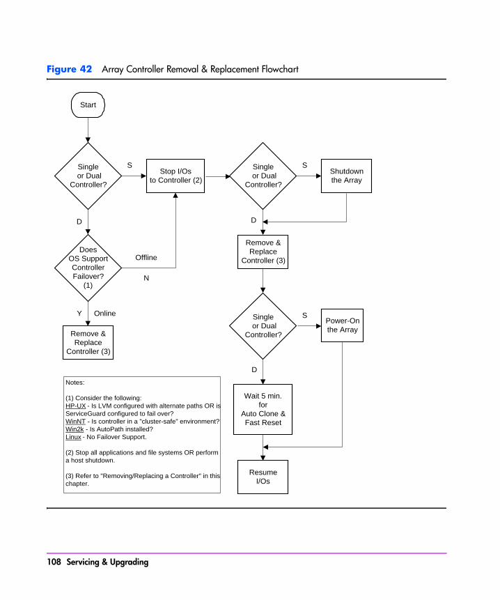
Figure 42 Array Controller Removal & Replacement Flowchart
Shutdownthe Array
Power-Onthe Array
Wait 5 min.for
Auto Clone &Fast Reset
ResumeI/Os
S
D
Single or Dual
Controller?
Single or Dual
Controller?
Remove &Replace
Controller (3)
Start
Single or Dual
Controller?
DoesOS SupportControllerFailover?
(1)
Stop I/Osto Controller (2)
Remove &Replace
Controller (3)
S
D
N
Offline
Y Online
S
D
Notes:
(1) Consider the following:HP-UX - Is LVM configured with alternate paths OR isServiceGuard configured to fail over?WinNT - Is controller in a "cluster-safe" environment?Win2k - Is AutoPath installed?Linux - No Failover Support.
(2) Stop all applications and file systems OR performa host shutdown.
(3) Refer to "Removing/Replacing a Controller" in thischapter.
108 Servicing & Upgrading

Servicing & U
pgrading
Caution The array controller can be damaged by electrostatic discharge. Use the ESD kit provided when removing and installing an array controller.
To prevent data loss, it is recommended that a full backup be performed before removing an array controller.
Do not operate the array for more than 5 minutes with an array controller or filler panel removed. Either an array controller or filler panel must be installed to maintain proper airflow in the controller enclosure. Use the foam in the replacement array controller packaging to temporarily plug the empty slot.
1 Perform any necessary prepatory steps indicated in Figure 42.
2 VA 7100: Remove the fiber optic cable from the GBIC (see Figure 39). VA 7110/7400/7410: Remove the fiber optic cables from the DISK FC and HOST FC connectors (see Figure 40).
3 VA 7100 only: Remove the GBIC (see Figure 39, 3).
4 VA 7100: Slide the latch (Figure 43, 1) all the way to the left. VA 7110/7400/7410: Loosen the cam lever screw (Figure 44, 1) with a T-10 driver or flat-blade screwdriver.
5 VA 7100: Press down the lock (Figure 43, 2) and pull out the cam lever (3). VA 7110/7400/7410: Pull out the cam lever (Figure 44, 2).
WARNING A hot surface is located on the underside of the array controller by the middle of the right-hand edge (facing the rear panel). To avoid burn injury, only touch the edges of the array controller. Do not touch the underside.
Caution When the cam lever is pulled out, an early warning switch is activated which suspends mirroring between dual controllers and terminates all I/Os to the controllers.
6 Grasp the cam lever and slide the array controller out 4 inches (10 cm) (Figure 43 or Figure 44).
7 Grasp the edges of the array controller with both hands and pull it out of the slot.
8 If the array controller was removed for a DIMM failure :Go to "Installing an Array Controller" on page 110.
Servicing & Upgrading 109
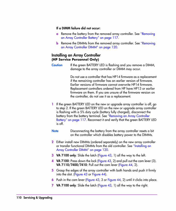
If a DIMM failure did not occur:
a Remove the battery from the removed array controller. See "Removing an Array Controller Battery" on page 117.
b Remove the DIMMs from the removed array controller. See "Removing an Array Controller DIMM" on page 120.
Installing an Array Controller (HP Service Personnel Only)
Caution If the green BATTERY LED is flashing and you remove a DIMM, damage to the array controller or DIMM may occur.
Do not use a controller that has HP14 firmware as a replacement if the remaining controller has an earlier version of firmware. Earlier versions of firmware cannot overwrite HP14 firmware. Replacement controllers ordered from HP have HP13 or earlier firmware on them. If you are unsure of the firmware version on the controller, do not use it as a replacement.
1 If the green BATTERY LED on the new or upgrade array controller is off, go to step 2. If the green BATTERY LED on the new or upgrade array controller is flashing with a 5% duty cycle (battery fully charged), disconnect the battery from the battery terminal. See "Removing an Array Controller Battery" on page 117. Reconnect it and verify that the green BATTERY LED is off.
Note Disconnecting the battery from the array controller resets a bit on the controller which disables battery power to the DIMMs.
2 Either install new DIMMs (ordered separately) on the new array controller or transfer functional DIMMs from the old controller. See "Installing an Array Controller DIMM" on page 120.
3 VA 7100 only: Slide the latch (Figure 43, 1) all the way to the left.
4 VA 7100: Press down the lock (Figure 43, 2) and pull out the cam lever (3). VA 7110/7400/7410: Pull out the cam lever (Figure 44, 2).
5 Grasp the edges of the array controller with both hands and push it firmly into the slot. (Figure 43 or Figure 44).
6 Push in the cam lever (Figure 43, 3 or Figure 44, 2) until it clicks into place.
7 VA 7100 only: Slide the latch (Figure 43, 1) all the way to the right.
110 Servicing & Upgrading
Servicing & U
pgrading
8 VA 7110/7400/7410 only: Tighten the cam lever screw (Figure 44, 1).
9 VA 7100 only: Replace the GBIC (Figure 39, 3).
10 Replace the fiber optic cables (see Figure 39 or Figure 40).
Note If you need to change the default Fibre Channel Loop ID on the array controller, use the following VFP command:
vfpmgr -L <loop id> -c <array controller card number>
Note The following step is only required if an HP-UX host is connected to the array using one of the following FC HBAs: A5158A, A6684A, A6685A, or A6795A.
11 From the HP-UX host, run the following command to allow the driver to use the new controller in the path: /opt/fcms/bin/fcmsutil device_file replace_dsk remote-N-Port-ID
Note A reboot of the host will also allow the driver to see the new controller. However, using the fcmsutil command is a much easier and quicker method of accomplishing this.
If you do not run the fcmsutil command, errors similar to the following will appear in syslog:
Unable to access previously accessed device at nport ID 0x2a. 'World-wide name' (unique identifier) for device at nport ID 0x2a has changed. If the device has been replaced intentionally, please use the fcmsutil(1M) command's replace_dsk option to allow the new device to be used. Fibre Channel Driver detected a parse error in the FLOGI/PLOGI response returned by nport ID 0x2a. FLOGI/PLOGI Fail Code = 0x6.
Servicing & Upgrading 111
Replacing the Controller in a Single-Controller ArrayReplacing a controller in a single-controller array is complicated by the fact that there is not a second controller to clone the firmware and maps. In this situation there are two alternatives for recovering the firmware and maps. The procedure used is determined by the nature of the controller failure.
Functioning Controller
If the original controller is functional, the following procedure is recommended:
1 Install the replacement controller with replacement DIMMs in the available controller slot and let the controller auto clone the firmware. The amount of memory on each controller must be the same.
2 Remove the original controller.
3 If desired, shutdown the array and move the new controller to the original slot.
Failed Controller
If the controller had a solid failure that precludes autocloning, the following procedure is recommended:
1 Determine what version of firmware was installed on the failed controller.
2 Replace the failed controller.
3 Power on the array. It will come up with a status of NO MAPs.
4 Update the controller firmware to the version that the array was running. Do not update to a different version.
5 Verify the firmware update completed successfully.
6 Issue the vfprecover command, and wait for the recovery to complete.
Note When a recover is performed, the controller must have the same version of firmware as the original controller and the array must have the same disks that were included in the configuration when the maps were created.
112 Servicing & Upgrading
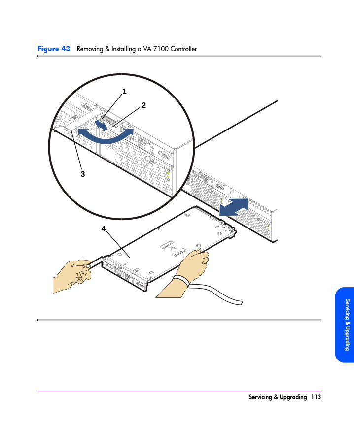
Servicing & U
pgrading
Figure 43 Removing & Installing a VA 7100 Controller
1
2
3
4
Servicing & Upgrading 113

Figure 44 Removing & Installing a VA 7110/7400/7410 Array Controller
1 2
3
114 Servicing & Upgrading
Servicing & U
pgrading
Array Controller Filler Panels
Removing an Array Controller Filler PanelCaution Do not operate the array for more than 5 minutes with an array
controller or filler panel removed. Either an array controller or filler panel must be installed in the slot to maintain proper airflow.
1 Loosen the cam lever screws (Figure 45, 1) with a T-10 driver or flat-blade screwdriver.
2 Pull out both cam levers (2) at the same time.
3 Pull the array controller filler panel (3) out of the slot.
Installing an Array Controller Filler Panel
1 Pull out both cam levers (Figure 45, 2) at the same time.
2 Push the array controller filler panel (3) firmly into the slot.
3 Push in both cam levers at the same time.
4 Tighten the cam lever screws (Figure 45, 1).
Servicing & Upgrading 115

Figure 45 Removing & Installing an Array Controller Filler Panel
1 2
3
116 Servicing & Upgrading
Servicing & U
pgrading
Array Controller BatteriesCaution Removing an array controller battery may cause data loss. The
battery supplies power to the DIMMs on the array controller card. To prevent data loss, you must either ensure the array is in a dual array controller configuration, or you must perform an array shutdown.
If the array is in a dual array controller configuration, it is recommended that you replace both array controller batteries.
The array controller battery is a Lithium ion type. When removed, the battery must be recycled or disposed of properly. Replace the battery only with the same type.
Shelf life for the array controller battery is rated for up to 6 months at a maximum temperature of 25º C. If this storage temperature or duration is exceeded, it may be necessary to recharge the battery during normal operation of the controller.
Removing an Array Controller Battery
1 Remove the array controller card. See "Removing an Array Controller" on page 107.
2 Loosen the battery clamp screw (Figure 46, 1) with a T-20 driver.
3 Lift the battery clamp (Figure 46, 2) off of the battery.
4 Lift the battery connector (Figure 47, 1) off of the battery terminal (Figure 47, 2).
5 Lift the battery (Figure 47, 3) off of the array controller card.
Servicing & Upgrading 117
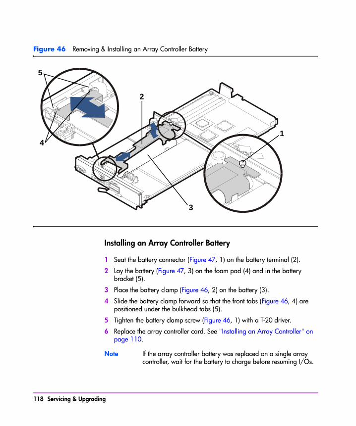
Figure 46 Removing & Installing an Array Controller Battery
Installing an Array Controller Battery
1 Seat the battery connector (Figure 47, 1) on the battery terminal (2).
2 Lay the battery (Figure 47, 3) on the foam pad (4) and in the battery bracket (5).
3 Place the battery clamp (Figure 46, 2) on the battery (3).
4 Slide the battery clamp forward so that the front tabs (Figure 46, 4) are positioned under the bulkhead tabs (5).
5 Tighten the battery clamp screw (Figure 46, 1) with a T-20 driver.
6 Replace the array controller card. See "Installing an Array Controller" on page 110.
Note If the array controller battery was replaced on a single array controller, wait for the battery to charge before resuming I/Os.
5
4
2
3
1
118 Servicing & Upgrading
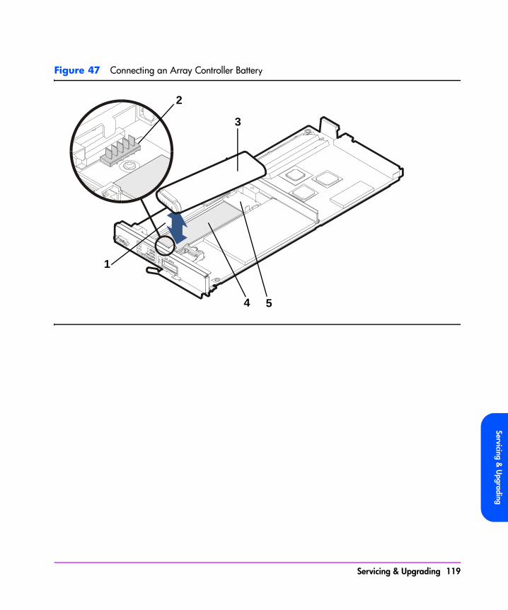
Servicing & U
pgrading
Figure 47 Connecting an Array Controller Battery
1
3
4 5
2
Servicing & Upgrading 119

Array Controller DIMMs
Removing an Array Controller DIMM (HP Service Personnel Only)
Caution DIMMs can be damaged by electrostatic discharge. Use the ESD kit provided when removing and installing DIMMs.
The following procedures are used when removing/installing DIMMs on a single controller. If you are upgrading the DIMMs on both controllers, you must shutdown the array. See "Upgrading Array Controller DIMMs" on page 135.
1 Remove the array controller card. See "Removing an Array Controller" on page 107.
2 Remove the battery. See "Removing an Array Controller Battery" on page 117.
Caution The battery must be removed to ensure there is no power to the DIMMS and to prevent damage to DIMMs caused by voltage spikes. After removing the battery, wait 2 minutes before removing DIMMs. This allows any residual charge to drain from the DIMMs.
3 Use your thumbs to pull out both DIMM extraction levers (Figure 48, 1) at the same time. The DIMM will automatically pop out of the DIMM slot.
4 Remove the DIMM (2) from the slot.
Installing an Array Controller DIMM (HP Service Personnel Only)
Caution
— DIMMs can be damaged by electrostatic discharge. Use the ESD kit provided when removing and installing DIMMs.
— To avoid interference when installing DIMMs, always load the DIMM 1 slot first (see Figure 48, 2).
— Controller firmware 13 and earlier supports a maximum of 1 Gbyte of cache memory per controller. Installing more than 1 Gbyte of memory can cause data loss.
— Replacement DIMMs must have the same memory size as the DIMMs being replaced. Otherwise, the array controller will report a “Memory Mismatch”. If the array is powered-on after the array controller is
120 Servicing & Upgrading

Servicing & U
pgrading
replaced offline, power-on initialization will not complete if the DIMM memory in both array controllers does not match.
1 Insert the DIMM (Figure 48, 2) evenly into the DIMM slot.
2 Use your thumbs to apply even pressure to the top edge of the DIMM and push the DIMM firmly into the slot. The DIMM extraction levers (1) will automatically capture the DIMM.
3 Replace the battery. See "Installing an Array Controller Battery" on page 118.
4 Replace the array controller card. See "Installing an Array Controller" on page 110.
Figure 48 Removing & Installing an Array Controller DIMM
1
2
Servicing & Upgrading 121

Midplane AssemblyCaution
— To prevent data loss, it is recommended that a full backup be performed before removing a midplane assembly.
— The midplane assembly can be damaged by electrostatic discharge. Use the ESD kit provided when removing and installing the midplane assembly.
— The midplane assembly is tied directly to the enclosure. Once a midplane assembly has been installed in an enclosure, you cannot re-use it in another enclosure. The serial number and worldwide name (WWN) of the enclosure are stored in redundant EEPROMs on the midplane assembly.
Removing a Midplane Assembly (HP Service Personnel Only)
1 Perform an array shutdown.
2 Remove all of the disk drives. See "Removing a Disk Drive" on page 98.
Note The controllers and power modules do not need to be completely removed from the array chassis - only disengaged.
3 Disengage the array controller cards 1 inch (2.5 cm) from the midplane. See "Removing an Array Controller" on page 107.
4 Disengage the power modules 1 inch (2.5 cm) from the midplane. See "Removing a Power Module" on page 102.
5 Racked arrays only: Remove the chassis mounting screws from the rack and pull the array chassis 2 inches (5 cm) out of the rack.
Note Verify that pulling the array chassis out of the rack will not stress or damage the cables connected to the rear of the chassis.
Deskside arrays only: Remove the chassis from the deskside assembly (see HP StorageWorks VA 7100 Deskside Assembly Conversion Kit Instructions).
6 Remove the front bezel (Figure 49, 1).
7 Remove three T-10 screws (2) from the chassis top cover (6).
122 Servicing & Upgrading

Servicing & U
pgrading
8 Using a flat-blade screwdriver, push up the two front top-cover side-clips (3) and pop the top cover up slightly.
9 Twist the screwdriver blade in the rear gaps (4) on the side of the chassis, directly behind the top cover.
10 Place a screwdriver blade in a vertical position in the slots (5) on top of the chassis directly behind the top cover. Hit the handle of the screwdriver with the palm of your hand until the top cover moves forward 3/16 inch (0.5 cm).
11 Slide the top cover (6) off the chassis.
12 Lift the lightpipe (7) out of the chassis slots and remove it from the chassis.
13 Press the power/standby switch shaft (8) all the way in and remove it from the chassis.
14 With the T-15 driver provided in the midplane assembly kit, remove 9 screws (9) from the midplane assembly.
15 Remove the midplane assembly (10) from the chassis.
Installing a Midplane Assembly (HP Service Personnel Only)
Note Installing a midplane assembly is the reverse of removing a midplane assembly.
Servicing & Upgrading 123
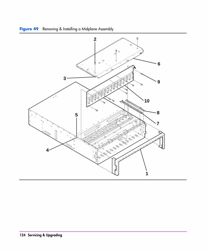
Figure 49 Removing & Installing a Midplane Assembly
2
1
4
5 8
7
9
10
6
3
124 Servicing & Upgrading
Servicing & U
pgrading
Disk Enclosure Removal & Installation Procedures
Disk DrivesSee "Disk Drives" on page 98 for information on removing and installing disk drives.
Disk Drive Filler PanelsSee "Disk Drive Filler Panels" on page 100 for information on removing and installing disk drive filler panels.
Power Modules
Removing a Power ModuleCaution Do not operate the array for more than 2 minutes with a power
module removed, or the array may automatically initiate a shutdown. At least one power module must be installed and operational at all times to maintain adequate power and airflow.
Always disconnect the power cord from the power module before removing it from the enclosure. Failure to disconnect power may result in power spikes that could damage the disk drives.
1 Disconnect the power cord.
2 Loosen the cam lever screws (Figure 50, 1) with a T-10 driver or flat-blade screwdriver.
3 Pull out both cam levers (2) at the same time.
4 Pull the power module (3) out of the slot.
Installing a Power Module
1 Pull out both cam levers (Figure 50, 2) at the same time.
2 Push the power module (3) firmly into the slot.
3 Push in both cam levers at the same time.
Servicing & Upgrading 125
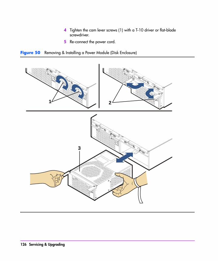
4 Tighten the cam lever screws (1) with a T-10 driver or flat-blade screwdriver.
5 Re-connect the power cord.
Figure 50 Removing & Installing a Power Module (Disk Enclosure)
1 2
3
126 Servicing & Upgrading
Servicing & U
pgrading
Link Controller Cards (LCCs)Caution The LCC can be damaged by electrostatic discharge. Use the
ESD kit provided when removing and installing an LCC.
The DS 2400 Disk System and the DS 2405 Disk System use different LCCs. Do not mix LCCs in the same disk enclosure.
To prevent data loss, it is recommended that a full backup be performed before removing an LCC.
Do not operate the disk enclosure for more than 5 minutes with an LCC removed. An LCC must be installed in the slot to maintain proper airflow in the enclosure. If necessary, use the foam in the replacement LCC packaging to temporarily fill the slot.
Removing an LCC (HP Service Personnel Only)
1 Remove the fiber optic cables (Figure 51, 1 and 2).
Note Depending on your configuration, Port 0 or Port 1 FC connectors may or may not have a fiber optic cable connected to it. Loopback cables are neither required nor recommended on unused FC connectors.
2 Loosen the cam lever screw (Figure 52, 1) with a T-10 driver or flat-blade screwdriver.
3 Pull out both cam levers (2) at the same time.
4 Pull the LCC (3) out of the slot.
Installing an LCC (HP Service Personnel Only)
1 If the LCC is being installed in a DS 2405 Disk System attached to a VA 7400, set the FC Loop Speed switch on the LCC to the 1GB/s position. See Figure 53.
Note The FC Loop Speed switch does not have to be changed when installing an LCC in a DS 2405 attached to a VA 7410 or VA 7110. The default 2GB/s setting is used on these products.
Servicing & Upgrading 127
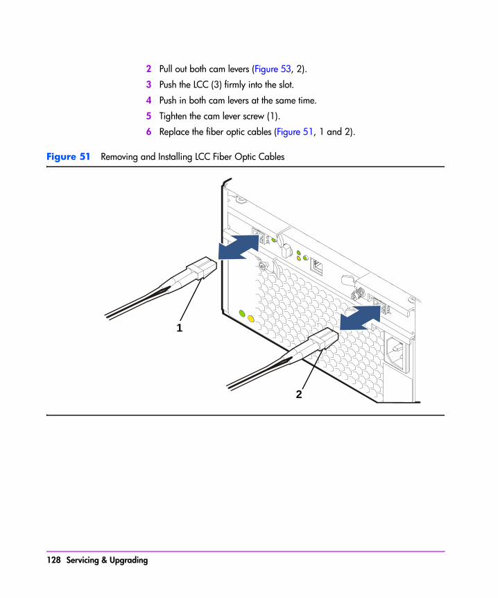
2 Pull out both cam levers (Figure 53, 2).
3 Push the LCC (3) firmly into the slot.
4 Push in both cam levers at the same time.
5 Tighten the cam lever screw (1).
6 Replace the fiber optic cables (Figure 51, 1 and 2).
Figure 51 Removing and Installing LCC Fiber Optic Cables
2
1
128 Servicing & Upgrading

Servicing & U
pgrading
Figure 52 Removing and Installing an LCC
1 2
3
Servicing & Upgrading 129

Figure 53 Setting the FC Loop Speed Switch
Must be set to 1GB/s
130 Servicing & Upgrading

Servicing & U
pgrading
Midplane Assembly
Note The controller enclosure and the disk enclosure both use the same midplane assemblies. To remove and replace a midplane assembly in the disk enclosure, follow the steps under "Removing a Midplane Assembly" on page 122 and "Installing a Midplane Assembly" on page 123, except in step 3, you will disengage (when removing) or re-engage (when installing) the LCCs. See "Removing an LCC" on page 127.
Servicing & Upgrading 131

Upgrading the Array
Increasing Storage Capacity
Adding a New Disk ModuleA new disk drive may be added online to the controller and disk enclosures at any time to upgrade storage capacity in the array. See "Installing a Disk Drive" on page 98 to add a disk. If the Auto Include feature is enabled, the array controller will automatically include the new disk in the array. However, a new LUN must be created in order to make the new capacity available to the host.
Adding Multiple Disks
If you are adding multiple disks, perform the following steps to avoid adding multiple bad disks to the array. Each redundancy group is designed to protect against a single disk failure. Multiple simultaneous failures can result in data loss. Manufacturing or mishandling can cause early failures in disks. If the disks are known to be good, they can all be installed simultaneously.
1 Install one disk module in each redundancy group (one odd slot and one even slot).
2 Wait until the disk format operation is complete and the disks come online. Use Command View to monitor the disk status.
3 Repeat for the next set of disks. Repeat until all disk modules have been installed.
Adding a New Disk Enclosure (VA 7110/7400/7410 Only)A new disk enclosure can be added to a VA 7400 or VA 7410 without powering down the array. The disk modules in the new enclosure will be detected by the array and will immediately be made available for use.
Here are some things to remember when adding a disk enclosure:
— If practical, new disk enclosures should be added during a period of lower activity. This minimizes the unlikely event that the reset generated by the disk Fibre Channel hot plug will impact the server workload.
— When adding a disk enclosure to a VA 7410, connect the enclosure to the back-end FC loop that has fewer disks. Remember that the disks in
132 Servicing & Upgrading
Servicing & U
pgrading
the controller enclosure are on loop 1. Consequently, the number of disk enclosures on loop 1 should always be equal to or one less than the number of enclosures on loop 2.
— If the disk enclosure being added is a DS 2405 Disk System, make sure the array controller firmware is HP14 or later. Earlier versions of controller firmware will not recognize the DS 2405, and may cause the array to generate a Phantom Enclosure warning state.
1 Install the new disk enclosure in the rack.
2 If a DS 2405 Disk System is being added to a VA 7400, set the FC Loop Speed switch on each LCC controller to 1GB/s. See Figure 53 on page 130. This step is not required on the VA 7410 or VA 7110, which have a 2 Gbit/sec back end.
3 Set the address switches on the rear of the disk enclosure to an address (0 - 5) that does not conflict with any of the other disk enclosures. Both address switches must be set to the same address. See Figure 9 on page 32 or Figure 10 on page 33.
4 Connect the power cords to the disk enclosure and power on the enclosure.
5 Wait for the disks to spin up and check that the LED status light on each disk module goes out after spin up.
On a VA 7400, also check the 2G LED on each LCC to ensure that it is off. If the LED is on, the FC Loop Speed switch is set to 2GB/s.
6 Using the disk module removal lever, disengage all disk modules from the enclosure backplane. Slide the modules one-quarter of the way out of the enclosure.
7 Using the fiber optic cables provided, connect the disk enclosure into the array configuration using the available unused Fibre Channel port on each loop. See Figure 9 on page 32 (VA 7400) or Figure 10 on page 33 (VA 7410) for recommended cabling configuration.
Note The following step minimizes the risk associated with unintentionally introducing multiple bad disks to the array. Manufacturing or mishandling can cause early failures in the disks. Each redundancy group is designed to protect against a single disk failure. Multiple simultaneous failures can result in data loss. If the disks are known to be good, they can all be reinstalled simultaneously.
Servicing & Upgrading 133
8 Reinstall one disk module in each redundancy group (one odd slot and one even slot) and wait until the disk format operation is complete and the disks come online. Use Command View to monitor the disk status.
When the disks have come online, repeat this step for the next set of disks. Repeat until all disk modules have been installed.
Note There is only one redundancy group on the VA 7110, so only one disk module at a time should be installed.
9 Check the status of the array to ensure it is operating normally.
Note If the disk enclosure was installed on a VA 7400 and the LUNs on the array are no longer visible, it indicates that the FC Loop Speed switches were not set to 1GB/s as instructed in step 2. Power off the disk enclosure and repeat the above procedure.
If the disks in the new enclosure are formatted with 512-byte sectors, they will be reformatted to 520-byte sectors. This process may take up to 60 minutes to complete, depending on disk drive capacity and system availability. See Table 23 on page 99 for raw format times. During this time, the green disk activity LED will be flashing.
Upgrading Single to Dual Array Controllers(HP Service Personnel Only)
Caution To prevent data loss, it is recommended that a full backup be performed before starting this procedure.
An array with a single array controller can be upgraded to a dual array controller configuration by adding an upgrade array controller.
To upgrade from a single to a dual array controller configuration:
1 Install DIMMs (ordered separately) on the upgrade controller. See "Installing an Array Controller DIMM" on page 120.
2 Install the upgrade array controller. See "Installing an Array Controller" on page 110.
134 Servicing & Upgrading

Servicing & U
pgrading
Upgrading Array Controller DIMMs (HP Service Personnel Only)
The amount of controller cache can be increased by adding a second DIMM to each controller, or by replacing existing DIMMs with higher capacity DIMMs. Regardless of which strategy is used, both controllers must have the same DIMM configuration. Valid DIMM configurations are listed in Table 25.
Before beginning the upgrade, make sure you have the required DIMMs.
Caution Make sure you observe the following precautions.
— It is recommended that a full backup be performed before starting this procedure.
— The array must be in a READY state before upgrading cache. The array must then be shutdown successfully and powered off before upgrading the controller DIMMs. Failure to shutdown the array could result in data loss.
— The only DIMM supported in the VA7410 and VA7110 is part number A6186-60002. If the array being upgraded is using other DIMMs, the DIMMs must be replaced with the correct part. Failure to use the correct part can result in data errors.
— Controller firmware versions HP13 and earlier support a maximum of 1 Gbyte of cache per controller on the VA 7400 and VA 7100. Installing more than 1 Gbyte of memory can cause data loss. The VA 7410 supports a maximum of 2 Gbyte of cache per controller.
— Once the amount of cache has been upgraded, the process for returning to the original configuration involves reformatting the entire array. See "Reducing the Size of Cache Memory" on page 136 for more information on what is involved.
— The DIMM in slot 1 must have the same memory size as the DIMM in slot 2. Otherwise, the controller will report a “Memory Mismatch”.
1 Alert all users that the array will be taken down. Dismount all volumes on the hosts accessing the array.
2 Ensure that the array is in a READY state, and then shutdown the array using CommandView SDM or the VFP. Make sure the array shutdowns successfully.
3 When the shutdown is complete, power off the array. See "Operating the Power/Standby Switch" on page 35.
4 Remove one of the controllers. See "Removing an Array Controller" on page 107.
Servicing & Upgrading 135
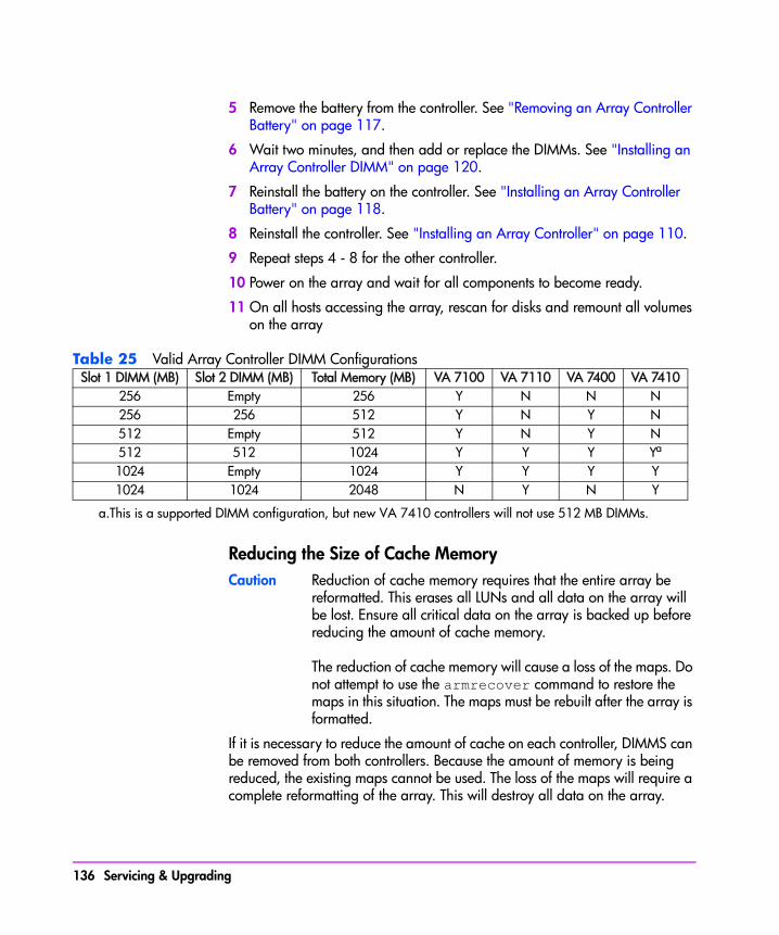
5 Remove the battery from the controller. See "Removing an Array Controller Battery" on page 117.
6 Wait two minutes, and then add or replace the DIMMs. See "Installing an Array Controller DIMM" on page 120.
7 Reinstall the battery on the controller. See "Installing an Array Controller Battery" on page 118.
8 Reinstall the controller. See "Installing an Array Controller" on page 110.
9 Repeat steps 4 - 8 for the other controller.
10 Power on the array and wait for all components to become ready.
11 On all hosts accessing the array, rescan for disks and remount all volumes on the array
Table 25 Valid Array Controller DIMM Configurations
Reducing the Size of Cache MemoryCaution Reduction of cache memory requires that the entire array be
reformatted. This erases all LUNs and all data on the array will be lost. Ensure all critical data on the array is backed up before reducing the amount of cache memory.
The reduction of cache memory will cause a loss of the maps. Do not attempt to use the armrecover command to restore the maps in this situation. The maps must be rebuilt after the array is formatted.
If it is necessary to reduce the amount of cache on each controller, DIMMS can be removed from both controllers. Because the amount of memory is being reduced, the existing maps cannot be used. The loss of the maps will require a complete reformatting of the array. This will destroy all data on the array.
Slot 1 DIMM (MB) Slot 2 DIMM (MB) Total Memory (MB) VA 7100 VA 7110 VA 7400 VA 7410256 Empty 256 Y N N N256 256 512 Y N Y N512 Empty 512 Y N Y N512 512 1024 Y Y Y Ya
a.This is a supported DIMM configuration, but new VA 7410 controllers will not use 512 MB DIMMs.
1024 Empty 1024 Y Y Y Y1024 1024 2048 N Y N Y
136 Servicing & Upgrading
Servicing & U
pgrading
1 Backup any data on the array that you wish to keep. You may also want to record the LUN structure on the array. You will need to recreate it after formatting the array.
2 Perform the steps in "Upgrading Array Controller DIMMs" on page 135, removing or replacing DIMMs as required. The cache must be reduced on both controllers.. After powering on the array, continue with the following steps.
3 Check the status of the array. It should indicate No Maps.
4 Format the array using CommandView SDM or the VFP.
5 Recreate the original LUN structure on the array.
6 Reload any backed up data.
Upgrading Array Controller Firmware (HP Service Personnel Only)
Caution To prevent data loss, it is recommended that a full backup be performed before starting this procedure.
Note When downloading controller firmware, always check the README file included with the firmware. (If you have access, you can also read the HP Service Note associated with the firmware download.) This information will identify whether you can perform the firmware download offline or online.
1 Download new firmware to an active array controller using CommandView SDM. See “Upgrading Array Controller Firmware” in the on-line Help.
The download process copies the new firmware to the other array controller automatically.
Note When firmware microcode is fully downloaded, the array controller suspends I/Os for about 10 seconds, then switches to the new code.
Upgrading Link Controller Card Firmware (HP Service Personnel Only)
Caution To prevent data loss, it is recommended that a full backup be performed before starting this procedure.
Servicing & Upgrading 137

Only wrapped firmware files should be used when downloading LCC firmware. This will prevent downloading the wrong firmware to the LCC.
Download new firmware to an LCC using HP CommandView SDM software. (See “Upgrading LCC Firmware” in the Help System.)
Upgrading Disk Firmware (HP Service Personnel Only)
Caution To prevent data loss, it is recommended that a full backup be performed before starting this procedure.
Download new firmware to a disk drive using HP CommandView SDM software. (See “Upgrading Disk Firmware” in the Help System.)
138 Servicing & Upgrading

5
Specifications & Regulatory StatementsThis chapter includes product specification data and all applicable product regulatory statements.
Specifications & Regulatory Statements 139
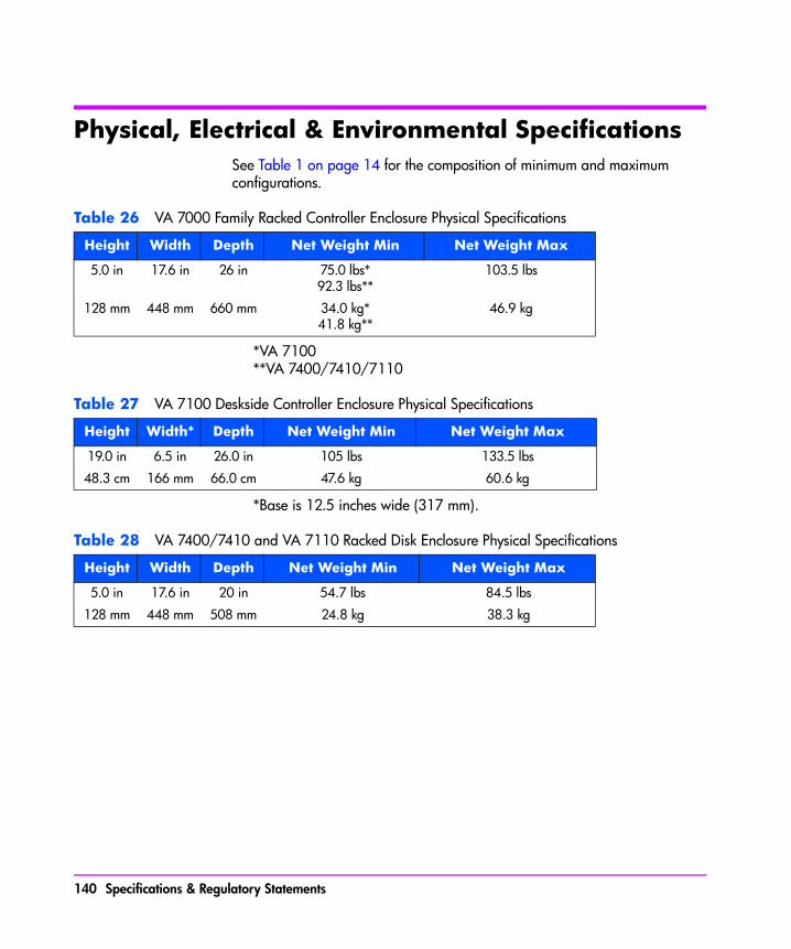
Physical, Electrical & Environmental SpecificationsSee Table 1 on page 14 for the composition of minimum and maximum configurations.
Table 26 VA 7000 Family Racked Controller Enclosure Physical Specifications
*VA 7100**VA 7400/7410/7110
Table 27 VA 7100 Deskside Controller Enclosure Physical Specifications
*Base is 12.5 inches wide (317 mm).
Table 28 VA 7400/7410 and VA 7110 Racked Disk Enclosure Physical Specifications
Height Width Depth Net Weight Min Net Weight Max
5.0 in 17.6 in 26 in 75.0 lbs*92.3 lbs**
103.5 lbs
128 mm 448 mm 660 mm 34.0 kg*41.8 kg**
46.9 kg
Height Width* Depth Net Weight Min Net Weight Max
19.0 in 6.5 in 26.0 in 105 lbs 133.5 lbs
48.3 cm 166 mm 66.0 cm 47.6 kg 60.6 kg
Height Width Depth Net Weight Min Net Weight Max
5.0 in 17.6 in 20 in 54.7 lbs 84.5 lbs
128 mm 448 mm 508 mm 24.8 kg 38.3 kg
140 Specifications & Regulatory Statements

Specifications & Regulatory
Statements
Table 29 Controller & Disk Enclosures Electrical Specifications
*Current rating is with 2 inputs
ElectricalParameter Controller Enclosure Disk Enclosure
Voltage(Auto-Ranging)
100-127 Vac;200-240 Vac
100-127 Vac;200-240 Vac
Current(Maximum)*
6.85 A @ 100 Vac;5.71 A @ 120 Vac;3.43 A @ 200 Vac;2.98 A @ 230 Vac
4.8 A @ 100 Vac;4.0 A @ 120 Vac;2.3 A @ 200 Vac;2.1 A @ 230 Vac
Frequency 50/60 Hz 50/60 Hz
Inrush Current(Peak)
36 A 17.5 A
PowerConsumption
670 W 500 W
HeatDissipation
2288 BTU/hr 1611 BTU/hr
VARating
685 VA 500 VA
Specifications & Regulatory Statements 141

Table 30 Controller & Disk Enclosures Environmental Specifications
EnvironmentalParameter
ControllerEnclosure
DiskEnclosure
Temperature Op: 5° to 35° C (41° to 95° F)Non-Op: -40° to 70° C (-40° to 158° F)
Op: 5° to 40° C (41° to 104° F)Non-Op: -40° to 70° C (-40° to 158° F)
TemperatureGradient
20° C (68° F) per hour 20° C (68° F) per hour
Relative Humidity(Dry Bulb)
Op: 15% to 80% @ 35° C (95° F)Non-Op: 15% to 90% @ 35° C (95° F)
Op: 20% to 90% @ 26° C (78.8° F)Non-Op: 5% to 95% @ 65° C (149° F)
Shock Op: 4g, 11 ms, half sineNon-Op: 2.5-inch edge drops per side
Op: 4g, 11 ms, 20 low-impulse pulsesNon-Op: 1-inch edge drops per side
Vibration Op: 0.21g-rms, 5 to 500 Hz randomNon-Op: 2.09 g-rms, 5 to 500 Hz randomNon-Op: 0.5 g-peak, 5 to 500 Hz swept sine
Op: 0.21g-rms, 5 to 500 Hz randomNon-Op: 2.09 g-rms, 5 to 500 Hz randomNon-Op: 0.5 g-rms, 5 to 500 Hz swept sine
Altitude Op: 0 to 10,000 ft (0 to 3,048 m)Non-Op: 0 to 15,000 ft (0 to 4,572 m)
Op: 0 to 10,000 ft (0 to 3,048 m)Non-Op: 0 to 15,000 ft (0 to 4,572 m)
Acoustic(ISO 9296)
8.0 bel 8.0 bel
142 Specifications & Regulatory Statements

Specifications & Regulatory
Statements
Regulatory Statements
Electromagnetic Compatibility Compliance
Table 31 Controller Enclosure Electromagnetic Compatibility Compliance
Table 32 Disk Enclosure Electromagnetic Compatibility Compliance
Table 33 FCC EMC Statement (USA)
The Federal Communications Commission (in 47 CFR 15.105) has specified that the following notice be brought to the attention of the users of this product.
This equipment has been tested and found to comply with the limits for a Class A digital device, pursuant to Part 15 of the FCC Rules. These limits are designed to provide reasonable protection against harmful interference when the equipment is operated in a commercial environment. This equipment generates, uses, and can radiate radio frequency energy and, if not installed and used in accordance with the instruction manual, may cause harmful interference to radio communications. Operation of this equipment in a residential area is likely to cause harmful interference in which case the user will be required to correct the interference at his own expense. The end user of
Parameter Specification
Radiated &Conducted Emissions
FCC Class A & EN 55022:1998, CISPR-22: 1997 Level A
Immunity EN 55024: 1998 / CISPR-24: 1997
Harmonic Current IEC 61000-3-2: 1998 / EN 61000-3-2: 1995 + A14
Voltage Fluctuations& Flicker
IEC 61000-3-3: 1994 / EN 61000-3-3: 1995
Parameter Specification
Radiated &Conducted Emissions
FCC Class A & EN 55022:1998, CISPR-22: 1997 Level A
Immunity EN 55024: 1998 / CISPR-24: 1997
Harmonic Current IEC 61000-3-2: 1998 / EN 61000-3-2: 1995 + A14
Voltage Fluctuations& Flicker
IEC 61000-3-3: 1994 / EN 61000-3-3: 1995
Specifications & Regulatory Statements 143

this product should be aware that any changes or modifications made to this equipment without the approval of the manufacturer could result in the product not meeting the Class A limits, in which case the FCC could void the user's authority to operate the equipment.
IEC EMC Statement (Worldwide)
This is a CISPR 22 Class A product. In a domestic environment, this product may cause radio interference, in which case the user may be required to take adequate measures.
EMC Statement (Canada)
This Class A digital apparatus meets all requirements of the Canadian Interference-Causing Equipment Regulations.
Cet appareil numérique de la Classe A respecte toutes les exigences du Règlement sur le matériel brouilleur du Canada.
Spécification ATI Classe A (France)
DECLARATION D’INSTALLATION ET DE MISE EN EXPLOITATION d’un matériel traitement de l’information (ATI), classé A en fonction des niveaux de perturbations radioélectriques émis, définis dans la norme européenne EN 55022 concernant la Compatibilité Electromagnétique.
VCCI EMC Statement (Japan)
This equipment is in the Class A category information technology equipment based on the rules of Voluntary Control Council For Interference by Information Technology Equipment (VCCI). When used in a residential area, radio interference may be caused. In this case, user may be required to take appropriate actions.
Harmonics Conformance (Japan)
144 Specifications & Regulatory Statements
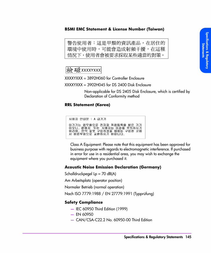
Specifications & Regulatory
Statements
BSMI EMC Statement & License Number (Taiwan)
XXXXYXXX = 3892H060 for Controller Enclosure
XXXXYXXX = 3902H045 for DS 2400 Disk Enclosure
Non-applicable for DS 2405 Disk Enclosure, which is certified by Declaration of Conformity method
RRL Statement (Korea)
Class A Equipment: Please note that this equipment has been approved for business purpose with regards to electromagnetic interference. If purchased in error for use in a residential area, you may wish to exchange the equipment where you purchased it.
Acoustic Noise Emission Declaration (Germany)
Schalldruckpegel Lp = 70 dB(A)
Am Arbeitsplatz (operator position)
Normaler Betrieb (normal operation)
Nach ISO 7779:1988 / EN 27779:1991 (Typprüfung)
Safety Compliance
— IEC 60950 Third Edition (1999)— EN 60950— CAN/CSA-C22.2 No. 60950-00 Third Edition
Specifications & Regulatory Statements 145

— UL 60950-2000
Electrical Safety
WARNING
— The product power cords are used as main disconnect devices. To ensure that the power cords can be disconnected quickly, locate the product near an easily accessible power outlet.
— Use only UL/CSA approved power cords, SVT type, rated for a suitable voltage and current. These power cords have two conductors and a ground. Failure to use the proper power cord may result in an electric shock or fire hazard.
— To avoid a fire hazard, the ac branch service must be properly current-protected by either a fuse or a circuit breaker. Hewlett-Packard recommends the use of magnetic-type circuit breakers, which are capable of handling large inrush currents for short durations (10-12 ms) and are rated adequately for the steady state currents. Also, make sure all equipment is properly grounded.
Class 1 Laser Safety Statement
A. Certification and Classification Information
This product contains a laser internal to the Small Form Factor (SSF) module for connection to the fiber communications port.
In the USA, the SSF module is certified as a Class 1 laser product conforming to the requirements contained in the Department of Health and Human Services (DHHS) regulation 21 CFR, Subchapter J. The certification is indicated by a label on the metallic SSF housing.
Outside the USA, the SSF is certified as a Class 1 laser product conforming to the requirements contained in IEC 825-1:1993 and EN 60825-1:1994, including Amendment 11:1996.
The SSF includes the following certifications:
* CSA Certified Component (Canada & US)
* TUV Certified Component (European Union)
The following figure shows the Class 1 information label that appears on the metal cover of the SSF housing:
146 Specifications & Regulatory Statements

Specifications & Regulatory
Statements
B. Product Information
Each communications port consists of a transmitter and receiver optical subassembly. The transmitter subassembly contains internally a semiconductor laser diode at a wavelength of 850 nanometers. In the event of a break anywhere in the fibre path, the SSF control system prevents laser emissions from exceeding Class 1 levels.
Class 1 laser products are not considered hazardous.
WARNING There are no user maintenance or service operations or adjustments to be performed on any SSF model.
C. Usage Restrictions
Failure to comply with these usage restrictions may result in incorrect operation of the system and points of access may emit laser radiation above Class 1 limits established by the IEC and the U.S. DHHS.
Battery Disposal Statement (Worldwide, Controller Enclosure Only)
Caution The Lithium Ion battery used in this product may be harmful to the environment if not disposed of properly. Please follow the local, state or country regulations regarding the proper disposal of these batteries.
Battery Disposal Statement (Netherlands, Controller Enclosure Only)
Bij dit produkt zijn batterijen geleverd. Wanneer deze leeg zijn, moet u ze niet weggooien maar inleveren als KCA.
CLASS 1 LASER
PRODUCT
Specifications & Regulatory Statements 147
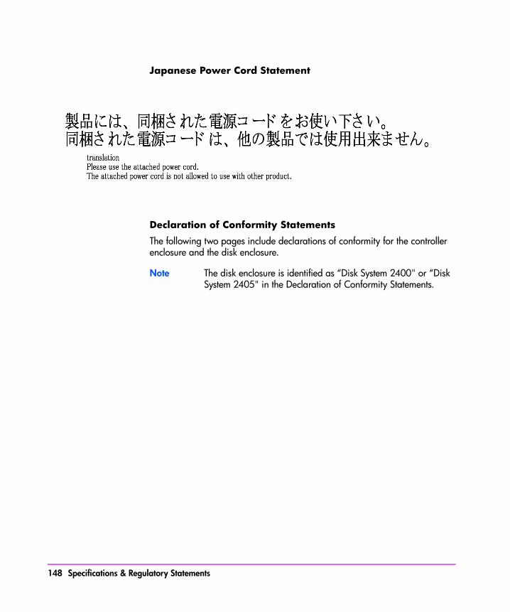
Japanese Power Cord Statement
Declaration of Conformity Statements
The following two pages include declarations of conformity for the controller enclosure and the disk enclosure.
Note The disk enclosure is identified as “Disk System 2400" or “Disk System 2405" in the Declaration of Conformity Statements.
148 Specifications & Regulatory Statements

Specifications & Regulatory
Statements
Specifications & Regulatory Statements 149
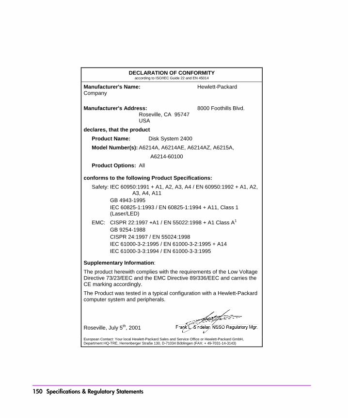
DECLARATION OF CONFORMITY according to ISO/IEC Guide 22 and EN 45014
Manufacturer's Name: Hewlett-Packard Company Manufacturer's Address: 8000 Foothills Blvd. Roseville, CA 95747 USA declares, that the product
Product Name: Disk System 2400 Model Number(s): A6214A, A6214AE, A6214AZ, A6215A, A6214-60100 Product Options: All conforms to the following Product Specifications:
Safety: IEC 60950:1991 + A1, A2, A3, A4 / EN 60950:1992 + A1, A2, A3, A4, A11
GB 4943-1995 IEC 60825-1:1993 / EN 60825-1:1994 + A11, Class 1
(Laser/LED) EMC: CISPR 22:1997 +A1 / EN 55022:1998 + A1 Class A1
GB 9254-1988 CISPR 24:1997 / EN 55024:1998 IEC 61000-3-2:1995 / EN 61000-3-2:1995 + A14 IEC 61000-3-3:1994 / EN 61000-3-3:1995
Supplementary Information: The product herewith complies with the requirements of the Low Voltage Directive 73/23/EEC and the EMC Directive 89/336/EEC and carries the CE marking accordingly. The Product was tested in a typical configuration with a Hewlett-Packard computer system and peripherals.
Roseville, July 5th, 2001
European Contact: Your local Hewlett-Packard Sales and Service Office or Hewlett-Packard GmbH, Department HQ-TRE, Herrenberger Straße 130, D-71034 Böblingen (FAX: + 49-7031-14-3143)
150 Specifications & Regulatory Statements
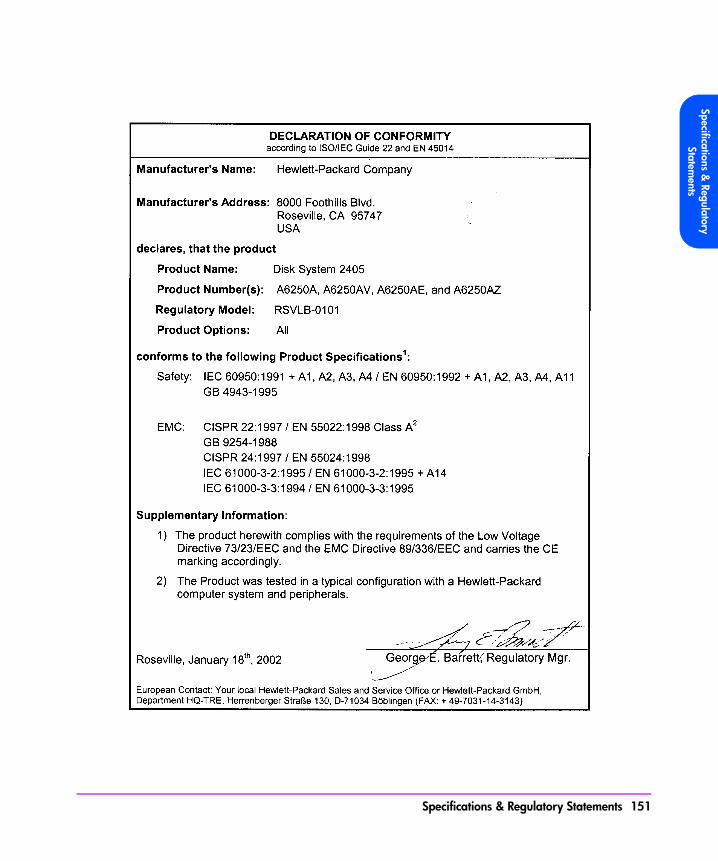
Specifications & Regulatory
Statements
Specifications & Regulatory Statements 151

152 Specifications & Regulatory Statements
index
Numerics7405 88
Aactive-active mode
array controller 24adding a disk enclosure 132adding a disk module 132array
advanced data protection 18electrical specifications 141environmental specifications 142image disks 27management software 16offline with shutdown 36operating with array controller
card removed 109operating with array controller
filler panel removed 115operating with controller filler
panel removed 26operating with disk drive filler
panel removed 28, 100operating with disk drive removed
98operating with link controller card
removed 127operating with power module
removed 102performance 17
power on 35power-on sequence 77readiness states 76scalability 17standby 35state and status 76status LEDs 76warning states 76
array controlleractive-active mode 24Auto Clone firmware copy process
107Fast Reset 107functions 24performing backup before
removing 109redundant data paths 24state parameters 76
array controller cardcam lever 109early warning switch 109installing 110installing DIMMs on replacement
110removal and replacement
flowchart 108removed for DIMM failure 109removing 107transferring DIMMs to replacement
153
110array controller card ESD kit 109array controller card type A
cam lever 109latch 109lock 109
array controller card type Bcam levers 109securing cam lever 111
array controller filler panelcam levers 115installing 115removing 115securing cam levers 115
array controller firmwaredownloading 137upgrading 137
array enclosurelightpipe 123
array management software, failureindicators 73Auto Clone
copying firmware 107autoranging
power supplies 28, 34
Bbackup
performing before removing array controller 109
performing before removing link controller card 127
performing before removing midplane 122
batterybracket 118clamp 117connector 117diminished storage capacity 26
discharged 25disconnecting to disable power to
DIMMs 110disposal 117, 147installing 118keeping valid memory maps 25life 25, 26Lithium Ion 117low charge 25operating temperature 25power to DIMMs 25recharged 25removing 117replacing in dual array controller
configuration 117self-test 25shelf life 117storage temperature 25storage time 25terminal 118waiting to charge before resuming
I/Os 118warning 25
battery LEDsfunctions 25indicating power to DIMMs 25status 82
bend radius, fiber optic cable connec-tors
covering on fiber optic cable 104blower
disk enclosure power module 34blowers
controller power module 28bracket
battery 118
154 Index

Ccache
reducing the amount of 136valid memory configurations 135
cam leverarray controller card 109array controller card type A 109disk drive 98, 100securing on array controller card
type B 111cam levers
array controller card type B 109array controller filler panel 115JBOD power module 125link controller card 127power module 102
capacitydisk drive 27
capacity, upgrading 132changing RAID mode on-line 47CLUI
checking controller logs 87state and status 85
configurationssystem 59
connectorsbattery 117
controller enclosureFRUs 93power modules 28
controller filler panelmust be installed 26
controller LEDs, status 82controller logs 86
checking with CLUI 87checking with CVUI 87in host OS directory 86in NVSDRAM 86
on image disks 86controller power module
blowers 28CRUs
servicing 92customer replaceable units
servicing 92customers
replacing field replaceable units 92
CVGUIstate and status 85
CVUIchecking array status 76checking controller logs 87state and status 85
Ddata map 25data map, logical-to-physical 38data protection 18
RAID 1+0 47RAID 5DP 48
data redundancyRAID 1+0 47RAID 5DP 48
data stripingRAID 1+0 47
dc circuitsactive in power on 35disabled in standby 35
deskside productsbase configurations 14
DIMM 120failure on array controller card
109installing 120removing 120slots 120
Index 155

DIMM LEDs, status 82DIMMs
data maps 25disabling power to 110electrostatic discharge 120ESD kit 120installing new on array controller
card 110Memory Mismatch 120NVSDRAM 25transferring old to replacement
array controller card 110upgrading 135valid configurations 135
dischargedbattery 25
disk driveAuto Format 98, 134automatically formatted to 520-
byte sectors 98, 134cam lever 98, 100formatted with 512-byte sectors in
factory 98, 134installing 98operating array while removed 98release button 98, 100removing 98spinning down before removing
98disk drive filler panel
installing 100must be installed 28operating array while removed
100removing 100
disk drive filler panel labelzero capacity 27
disk drive label
capacity, interface, rotational speed 27
disk drive LEDs, status 79disk drives
automatically included 26capacities 26configuring 26mixing capacities 26state parameters 76
disk enclosureFRUs 95identifying type of 92operating with power module
removed 125power modules 34
disk enclosure power moduleblower 34operating disk enclosure while
removed 125disk firmware
downloading 138upgrading 138
disposalbattery 147
disposal, battery 117downgrading cache memory 136downloading
array controller firmware 137disk firmware 138link controller firmware 137
downloading array controller firmware137
DS 2405 Disk Systemidentifying 92
dual array controller configurationreplacing batteries 117
dual inline memory module 120
156 Index

Eearly warning switch
activating on array controller card 109
suspending mirroring and terminating I/Os to dual array controllers 109
electromagnetic compatibility compli-ance 143electrostatic discharge
DIMMs 120EMS
critical severity 88error description 89event data 89event messages 89event severity levels 88information only 88major warning severity 88message data 89minor warning severity 88probable cause/recommended
action 89serious severity 88
enclosurescontroller 13disk 13Virtual Array 13
ESD kitarray controller card 109DIMMs 120link controller card 127midplane 122
event messagesEMS 89
Event Monitoring Servicehardware monitors 88
Ffactory-racked products
base configurations 14shipped in HP Rack System/E 13
failure indicatorsarray management software 73array status LEDs 73host applications 73
Fast Resetmirroring cache memory 107
FC Loop Speed switchsetting 130
FCC EMC Statement 143fiber optic cable
bend radius 104damage 104installing covers 104removing 104
field replaceable unitsidentifying 92
field-rackable productsbase configurations 14
filler paneldisk drive 27
flowchart, array controller card remov-al and replacement 108front bezel, removing 122front panel
activity during power-on self-test 36
FRUscontroller enclosure part numbers
93disk enclosure part numbers 95hot swappable 97identifying 92location of in controller enclosure
93
Index 157
location of in disk enclosure 95serviced by customers 92serviced by HP service personnel
only 92
GGBIC 106
connected to HOST FC connector (VA 7100) 26
installing in HOST FC slot 106installing on type A controller 106removing on type A array
controller 106tabs 106
gigabit interface converter 106
Hhost
OS directory for controller logs 86host applications, failure indicators 73HOST FC LEDs, status 80, 81HOST FC slot
for GBIC 106hot swappable
FRUs 97HP Rack System/E
default rack for factory-racked products 13
HP service personnelservicing field replaceable units
92
Iimage disks
controller logs 86copies of cache maps stored on
during shutdown 27resiliency maps updated on 27selecting 27
increasing capacity 132installing
array controller card 110array controller filler panel 115battery 118DIMM 120disk drive 98disk drive filler panel 100GBIC on type A controller 106link controller card 127midplane assembly 123power module in controller
enclosure 102power module in disk enclosure
125interface
disk drive 27
JJBOD See disk enclosure
Llatch, array controller card type A 109LCC ACTIVE LEDs, status 83LCC FAULT LEDs, status 83LED status
battery LEDs 82controller LEDs 82DIMM LEDs 82disk drive LEDs 79HOST FC LEDs 80, 81LCC ACTIVE LEDs 83LCC FAULT LEDs 83LINK ACTIVE LEDs 83power module LEDs 84system LEDs 78
lightpipeinstalling 123
158 Index

removing 123LINK ACTIVE LEDs, status 83link controller card
cam levers 127installing 127performing backup before
removing 127removing 127securing 128
link controller card ESD kit 127link controller firmware
downloading 137upgrading 137
Link Downcaused by array Fibre Channel
loop 76caused by host Fibre Channel loop
76reported when array FC loop fails
77reported when host FC loop fails
77warning state 76
link, Fibre Channel 76Lithium Ion, battery 117load sharing
power supplies 28, 34lock, array controller card type A 109logical drive
creating to make capacity available to host 26
logical-to-physical data map 25, 38logs
controller 86usage 86
low chargebattery 25
LUNsVA 7100 38
VA 7400 38
Mmemory 135memory maps
in DIMMs 25in NVSDRAM 25losing 25
Memory Mismatchwhen replacing DIMMs 120
midplaneESD 122not re-using in another array
enclosure 122world wide name 122
midplane assemblyinstalling 123removing 122
mirroringRAID 1+0 47
NNVSDRAM
controller logs 86data map 25memory maps 25
Ooperating systems
AIX 16HP-UX 16Linux 16MPE/iX 16native 16NetWare 16non-native 16Solaris 16supported 16
Index 159

Windows 16
Ppanels
VA 7100 deskside front and rear 20
VA 7100 rack front and rear 19VA 7400 JBOD front and rear 29VA 7400 rack front and rear 21,
22part numbers
controller enclosure FRUs 93disk enclosure FRUs 95fiber optic cables 96, 99rail kits 96, 99reference 96, 99RS-232 null modem cable 96, 99
performanceVA 7100 17VA 7400 17
performance path 45power
on 35removing by unplugging power
cords 35standby 35
power cord 102, 125power cords
unplugging to remove power 35power failure, recovery sequence 37power module
cam levers 102installing in disk enclosure 125operating controller enclosure
while removed 102power cord 102, 125removing in disk enclosure 125securing in controller enclosure
102securing in JBOD enclosure 126
power module LEDs, status 84power module, controller enclosure
installing 102removing 102
power module, JBODcam levers 125
power modulescontroller enclosure 28disk enclosure 34
power ondc circuits active 35
power suppliesautoranging 28, 34load sharing 28, 34
power/standby switchinitiating a shutdown 36operating 35
power/standby switch shaft, removingand replacing 123power-on
self-test 36power-on self-test 77
front panel activity 36successful completion 36
power-on sequence 77product configurations
VA 7100 14VA 7400 14
product featuresVA 7100 17VA 7400 17
Rracks
supported 14RAID 1+0
data protection 47
160 Index
data redundancy 47data striping 47mirroring 47
RAID 5DPdata protection 48data redundancy 48high read throughput 48write performance penalty 48
RAID modechanging on-line 47
read throughputRAID 5DP 48
readiness statesarray 76
rechargedbattery 25
recovery sequence, power failure 37reducing cache memory 136redundancy groups 39redundant data paths
array controller 24regulatory
compliance 143statements 143
release button, disk drive 98, 100removing
array controller card 107battery 117DIMM 120disk drive 98disk drive filler panel 100fiber optic cable 104GBIC on type A array controller
106link controller card 127midplane assembly 122power module in controller
enclosure 102
power module in disk enclosure 125
removing array controller filler panel115
resiliency mapsupdated on image disks 27
rotational speeddisk drive 27
Ssafety
electrical 146safety compliance 145scalability 17sectors
disk drive formatted from 512-byte to 520-byte sectors 98, 134
self-testbattery 25power-on 36, 77
shelf life, battery 117shutdown
initiating 36taking array offline 36
single to dual array controller, upgrad-ing 134slot
DIMM 120software
array management 16HP StorageWorks CommandView
SDM 16initiating a shutdown 36utilities 16
specificationsacoustic 142altitude limits 142current 141dimensions 140
Index 161
electrical 141electromagnetic compatibility
compliance 143environmental 142frequency 141heat dissipation 141power 141relative humidity 142temperature limits 142voltage 141weight 140
spinning downdisk drive to avoid damage to
spindle bearings 98standby
dc circuits disabled 35state
array controller 76with CLUI 85with CVGUI 85with CVUI 85with VFP 85
state and statusarray 76
statuschecking with CVUI 76checking with VFP 76with CLUI 85with CVGUI 85with CVUI 85with VFP 85
status LEDschecking 76failure indicators 73
system LEDs, status 78
Tterminal, battery 118
top cover, removing and replacing123
troubleshootingarray able to communicate with
host 76array unable to communicate with
host 76sequence 74steps 74
Uupgrading
array controller firmware 137capacity 132DIMMs 135disk firmware 138link controller firmware 137single to dual array controller 134
usage logs 86utilities
Command Line User Interface 16CommandView Graphical User
Interface 16CommandView User Interface 16
VVA 7100
128 LUNs allowed 38performance 17product configurations 14product description 13product features 17software 16supported racks 14
VA 7100 desksidefront and rear panels 20
VA 7100 rackfront and rear panels 19
162 Index
VA 74001024 LUNs allowed 38performance 17product configurations 14product description 13product features 17software 16supported racks 14
VA 7400 JBODfront and rear panels 29
VA 7400 rackfront and rear panels 21, 22
valid configurations 135VFP
checking array status 76state and status 85
virtual arraydefinition 38logical-to-physical data map 38
voltageautoranging 141
Wwarning states
Link Down 76warning states, array 76warning, battery 25warranty
HP hardware limited 7information 6
world wide namewritten in EEPROM on midplane
122write performance penalty
RAID 5DP 48
Index 163

164 Index